WO2022085182A1 - 静電分離装置及び方法 - Google Patents
静電分離装置及び方法 Download PDFInfo
- Publication number
- WO2022085182A1 WO2022085182A1 PCT/JP2020/039915 JP2020039915W WO2022085182A1 WO 2022085182 A1 WO2022085182 A1 WO 2022085182A1 JP 2020039915 W JP2020039915 W JP 2020039915W WO 2022085182 A1 WO2022085182 A1 WO 2022085182A1
- Authority
- WO
- WIPO (PCT)
- Prior art keywords
- raw material
- conductive particles
- material layer
- conveyor belt
- transport surface
- Prior art date
- Legal status (The legal status is an assumption and is not a legal conclusion. Google has not performed a legal analysis and makes no representation as to the accuracy of the status listed.)
- Ceased
Links
Images


Classifications
-
- B—PERFORMING OPERATIONS; TRANSPORTING
- B03—SEPARATION OF SOLID MATERIALS USING LIQUIDS OR USING PNEUMATIC TABLES OR JIGS; MAGNETIC OR ELECTROSTATIC SEPARATION OF SOLID MATERIALS FROM SOLID MATERIALS OR FLUIDS; SEPARATION BY HIGH-VOLTAGE ELECTRIC FIELDS
- B03C—MAGNETIC OR ELECTROSTATIC SEPARATION OF SOLID MATERIALS FROM SOLID MATERIALS OR FLUIDS; SEPARATION BY HIGH-VOLTAGE ELECTRIC FIELDS
- B03C7/00—Separating solids from solids by electrostatic effect
- B03C7/02—Separators
- B03C7/04—Separators with material carriers in the form of trays, troughs, or tables
-
- B—PERFORMING OPERATIONS; TRANSPORTING
- B03—SEPARATION OF SOLID MATERIALS USING LIQUIDS OR USING PNEUMATIC TABLES OR JIGS; MAGNETIC OR ELECTROSTATIC SEPARATION OF SOLID MATERIALS FROM SOLID MATERIALS OR FLUIDS; SEPARATION BY HIGH-VOLTAGE ELECTRIC FIELDS
- B03C—MAGNETIC OR ELECTROSTATIC SEPARATION OF SOLID MATERIALS FROM SOLID MATERIALS OR FLUIDS; SEPARATION BY HIGH-VOLTAGE ELECTRIC FIELDS
- B03C7/00—Separating solids from solids by electrostatic effect
- B03C7/02—Separators
- B03C7/08—Separators with material carriers in the form of belts
-
- B—PERFORMING OPERATIONS; TRANSPORTING
- B03—SEPARATION OF SOLID MATERIALS USING LIQUIDS OR USING PNEUMATIC TABLES OR JIGS; MAGNETIC OR ELECTROSTATIC SEPARATION OF SOLID MATERIALS FROM SOLID MATERIALS OR FLUIDS; SEPARATION BY HIGH-VOLTAGE ELECTRIC FIELDS
- B03C—MAGNETIC OR ELECTROSTATIC SEPARATION OF SOLID MATERIALS FROM SOLID MATERIALS OR FLUIDS; SEPARATION BY HIGH-VOLTAGE ELECTRIC FIELDS
- B03C7/00—Separating solids from solids by electrostatic effect
- B03C7/02—Separators
-
- B—PERFORMING OPERATIONS; TRANSPORTING
- B03—SEPARATION OF SOLID MATERIALS USING LIQUIDS OR USING PNEUMATIC TABLES OR JIGS; MAGNETIC OR ELECTROSTATIC SEPARATION OF SOLID MATERIALS FROM SOLID MATERIALS OR FLUIDS; SEPARATION BY HIGH-VOLTAGE ELECTRIC FIELDS
- B03C—MAGNETIC OR ELECTROSTATIC SEPARATION OF SOLID MATERIALS FROM SOLID MATERIALS OR FLUIDS; SEPARATION BY HIGH-VOLTAGE ELECTRIC FIELDS
- B03C7/00—Separating solids from solids by electrostatic effect
Definitions
- the present invention relates to an electrostatic separation device and a method for separating conductive particles from a raw material in which conductive particles and insulating particles are mixed.
- an electrostatic separation device that separates conductive particles by electrostatic force from a raw material in which conductive particles and insulating particles (non-conductive particles) are mixed has been known.
- Such an electrostatic separation device can be used for separating specific components from coal ash and waste (for example, waste plastic, garbage, incinerator ash, etc.), removing impurities from foods, concentrating minerals, and the like.
- Patent Document 1 discloses this kind of electrostatic separation device.
- the electrostatic separation device disclosed in Patent Document 1 includes a flat plate-shaped bottom electrode and a flat plate-shaped mesh electrode having a large number of openings installed above the bottom electrode, and a voltage is applied between both electrodes. A separation zone is formed between both electrodes by electrostatic force. Further, the bottom electrode is composed of a gas dispersion plate having air permeability, a dispersion gas is introduced into the separation zone from the lower side of the gas dispersion plate, and vibration is applied to at least one of the bottom electrode and the mesh electrode. As a result, the conductive particles in the raw material supplied to the separation zone pass through the opening of the mesh electrode and are separated above the separation zone. The conductive particles separated above the separation zone are airflow conveyed to the dust collector through the suction pipe and collected by the dust collector.
- Coal ash from thermal power plants contains unburned carbon (conductive particles) and ash (insulating particles).
- the coal ash from which unburned carbon has been removed is of high value as high-quality coal ash. Therefore, it is desirable to separate the unburned carbon from the coal ash so that the unburned carbon contained in the coal ash is less.
- the insulating particles may accompany the conductive particles protruding above the separation zone, and the ejected insulating particles are carried by air flow to the dust collector together with the conductive particles for recovery. Will be done. Under these circumstances, there is room for improvement in improving the purity of the conductive particles in the powder or granular material collected by the dust collector.
- the present invention has been made in view of the above circumstances, and an object thereof is from recovered conductive particles in an electrostatic separation device for separating conductive particles from a raw material in which conductive particles and insulating particles are mixed.
- the purpose is to increase the purity of the powder or granular material.
- the electrostatic separation device is an electrostatic separation device that separates the conductive particles from a raw material in which conductive particles and uncharged insulating particles are mixed.
- a container in which a raw material layer made of the raw materials is formed, and With the lower electrode arranged at the bottom of the raw material layer or in the raw material layer, A fluidized gas supply device that is introduced into the raw material layer from the bottom of the container and supplies the fluidized gas that rises in the raw material layer through the lower electrode.
- An upper electrode arranged above the raw material layer and An endless conveyor belt having a transport surface made of a non-conductor, having a capture region above the raw material layer and below the upper electrode, and rotating so that the downward transport surface passes through the capture region.
- a power supply device that applies a voltage between the upper electrode and the lower electrode so as to generate an electric field between these electrodes with one of the upper electrode and the lower electrode as a negative electrode and the other as a positive electrode.
- the same polarity as the upper electrode is made to appear on the surface by dielectric polarization, and the charged conductive particles are selectively separated from the raw material layer by electrostatic force to be attached to the transport surface of the conveyor belt, and are outside the electric field. It is characterized in that it is configured to separate and recover the conductive particles from the transport surface that has moved to.
- the electrostatic separation method is an electrostatic separation method for separating the conductive particles from a raw material in which conductive particles and uncharged insulating particles are mixed.
- the conductive particles charged with the same polarity as the lower electrode by contacting with the lower electrode in the raw material layer move to the surface layer by the flow of the raw material layer.
- Above the raw material layer there is a conveyor belt transport surface in which the polarity opposite to that of the charged conductive particles appears, and the conductive particles selectively pop out from the raw material layer and adhere to the transport surface due to electrostatic force. ..
- the insulating particles in the raw material layer are not charged by contact with the lower electrode. The transport surface is downward, and even if the insulating particles that have jumped out of the raw material layer try to adhere due to the force of flow, the insulating particles fall under their own weight.
- the particles captured on the transport surface of the conveyor belt are generally conductive particles.
- the conductive particles captured on the downward transport surface of the conveyor belt are transported out of the electric field by the rotation of the conveyor belt, separated from the transport surface of the conveyor belt outside the electric field, and recovered. .. Therefore, it is possible to suppress the mixing of the insulating particles into the powder or granular material made of the recovered conductive particles, and to increase the purity of the powder or granular material made of the recovered conductive particles.
- an electrostatic separation device that separates conductive particles from a raw material in which conductive particles and insulating particles are mixed, it is possible to increase the purity of the powder or granular material composed of the recovered conductive particles.
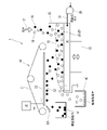
- FIG. 1 is a diagram showing an overall configuration of an electrostatic separation device according to an embodiment of the present invention.
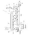
- FIG. 2 is a diagram showing a modified example of an electrostatic separation device provided with a container vibration device.
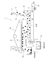
- FIG. 3 is a diagram showing a modified example of the electrostatic separation device in which the upper electrode is arranged on the outside of the ring of the conveyor belt.
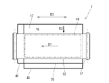
- FIG. 4 is a plan view showing the relationship between the moving direction of the transport surface of the conveyor belt and the traveling direction of the raw material.
- FIG. 5 is a diagram showing a modified example of an electrostatic separation device provided with an insulating particle desorption promoting device by a belt vibration method.
- FIG. 6 is a diagram showing a modified example of an electrostatic separation device provided with an insulating particle desorption promoting device by a gas permeation method.
- FIG. 1 is a diagram showing an overall configuration of an electrostatic separation device 1 according to an embodiment of the present invention.
- the electrostatic separation device 1 according to the present invention mainly separates the conductive particles 16 from the raw material 17 in which the conductive particles 16 and the insulating particles 18 are mixed.
- the electrostatic separation device 1 can be used, for example, to separate unburned carbon from coal ash (raw material 17) containing unburned carbon (conductive particles 16) and ash (insulating particles 18).
- the application of the electrostatic separation device 1 is not limited to the above, and is conductive or chargeable for separating various particles or powders, for example, separating metals from waste and removing impurities from mercury, minerals and foods. It can also be used to separate different substances.
- the electrostatic separation device 1 includes a container 25 on which the raw material layer 15 is formed, a lower electrode 28 arranged at the bottom of the raw material layer 15 or in the raw material layer 15, and a raw material. It includes an upper electrode 22 arranged above the layer 15, a fluidized gas supply device 29 for fluidizing the raw material layer 15, a conveyor device 50, and a power supply device 20.
- a gas dispersion member 26 having a large number of micropores is arranged at the bottom of the container 25.
- the gas dispersion member 26 may be a porous plate (that is, a gas dispersion plate) or a porous sheet.
- a raw material 17 in which conductive particles 16 and insulating particles 18 are mixed is supplied to the container 25 by a supply device (not shown).
- the raw material layer 15 is formed by the raw material 17 deposited on the lower electrode 28 in the container 25.
- an insulating particle recovery container 40 for recovering particles (mainly insulating particles 18) overflowing from the container 25 is provided.
- a wind box 30 is provided below the container 25.
- the fluidized gas 31 is supplied to the air box 30 from the fluidized gas supply device 29.
- the fluidized gas 31 may be, for example, air.
- the fluidized gas 31 is preferably a dehumidified gas (for example, a dehumidifying gas having a dew point of 0 ° C. or lower).
- the fluidized gas 31 is introduced into the raw material layer 15 from the bottom of the container 25, and rises in the raw material layer 15 while passing through the gas dispersion member 26 and the lower electrode 28.
- the raw material layer 15 is fluidized by the fluidized gas 31.
- a metal gas dispersion plate is adopted as the gas dispersion member 26, and this gas dispersion plate also has the functions of the gas dispersion member 26 and the lower electrode 28.
- the lower electrode 28 may be provided above the gas dispersion member 26 in the raw material layer 15.
- the lower electrode 28 is made of a mesh plate that allows the fluidized gas 31 to pass through, and a resin, metal, or ceramic porous sheet is used for the gas dispersion member 26.
- FIG. 2 is a diagram showing a modified example of the electrostatic separation device 1 provided with the container vibration device 32.
- the electrostatic separation device 1 may further include a container vibrating device 32 that vibrates the container 25.
- the container 25 vibrates, the lower electrode 28 fixed to the container 25 and behaves integrally with the container vibrates.
- the vibration of the container vibration device 32 the container 25 (and the lower electrode 28) may vibrate in any one of the vertical direction and the horizontal direction, or in the direction of two or more combinations.
- the vibration may be a reciprocating motion or a circular motion.
- the conveyor device 50 includes an endless conveyor belt 51 and a rotary drive device (not shown) for the conveyor belt 51.
- the upper electrode 22 is arranged inside the ring of the conveyor belt 51. However, as shown in FIG. 3, the upper electrode 22 may be arranged outside the ring of the conveyor belt 51.
- the outer surface of the ring of the conveyor belt 51 is a transport surface 52.
- the upper part of the raw material layer 15 and the lower part of the upper electrode 22 are defined as the “capture area 10”.
- the rotating conveyor belt 51 passes through the capture region 10 with the transport surface 52 facing downward.
- the transport surface 52 of the conveyor belt 51 passing through the capture region 10 may be substantially horizontal.
- FIG. 4 is a plan view showing the relationship between the moving direction D1 of the transport surface 52 of the conveyor belt 51 and the traveling direction D2 of the raw material 17.
- the traveling direction D2 of the raw material 17 is substantially orthogonal to the traveling direction D2 in the plan view.
- the container 25 has a large dimension in the width direction D3 orthogonal to the traveling direction D2.
- the moving direction D1 and the traveling direction D2 are shown in parallel in FIGS. 1 to 3 and 5, the relationship between the moving direction D1 and the traveling direction D2 is not limited to that shown in these drawings.
- the raw material 17 in the container 25 gradually moves in the traveling direction D2 from the first side to the second side of the container 25.
- the conductive particles 16 are charged and adhere to the transport surface 52 of the conveyor belt 51, so that the amount of the charged conductive particles 16 is in the traveling direction D2. It decreases from the upstream side to the downstream side.
- the conductive particles 16 adhering to the transport surface 52 of the conveyor belt 51 adhere and occupy the transport surface 52 until they are removed by the particle separation member 43, so that further adhesion of the conductive particles 16 is hindered. Become.
- the moving direction D1 and the traveling direction D2 are orthogonal to each other, the conductive particles 16 are more efficiently adhered and recovered on the transport surface 52 as compared with the case where the moving direction D1 and the traveling direction D2 are parallel to each other. Can be made to. If the moving direction D1 and the traveling direction D2 of the transport surface 52 of the conveyor belt 51 passing through the capture region 10 are parallel, the width of the conveyor belt 51 becomes large. From the viewpoint of suppressing the width of the conveyor belt 51 as described above, it is desirable that the moving direction D1 and the traveling direction D2 are orthogonal to each other in a plan view. However, the moving direction D1 and the traveling direction D2 may be parallel to each other.
- the conveyor belt 51 has at least a non-conductor on the transport surface 52. That is, the portion other than the transport surface 52 is not limited to the non-conductor.
- the conveyor belt 51 may be entirely composed of non-conductors.
- the conveyor belt 51 may be a steel cord conveyor belt having a steel cord inside. When a steel cord conveyor belt is adopted, the steel cord can be made to function as the upper electrode 22 by exposing the steel cord on the inner peripheral surface of the conveyor belt 51 and connecting it to the power supply device 20.
- a particle separating member 43 is attached to the conveyor device 50.
- a conductive particle recovery container 41 is provided below the particle separation member 43.
- the particle separating member 43 is, for example, a spatula-shaped member (scraper), and can scrape off particles adhering to the conveyor belt 51. However, even if the particle separation member 43 is a member having a static elimination function (for example, a static elimination brush) and removes the particles adhering to the conveyor belt 51 to separate the particles from the conveyor belt 51. good.
- FIGS. 5 and 6 are diagrams showing a modified example of the electrostatic separation device 1 provided with the insulating particle desorption promoting device 53. As shown in FIGS. 5 and 6, the electrostatic separation device 1 promotes the detachment of the insulating particles 18 adhering to the transport surface 52 or the conductive particles 16 of the conveyor belt 51 by the intramolecular force.
- the release promoting device 53 (53A, 53B) may be provided.
- the insulating particle desorption promoting device 53A shown in FIG. 5 is a belt vibration type.
- the insulating particle desorption promoting device 53A is configured to vibrate the transport surface 52 by contacting the downward transport surface 52 of the conveyor belt 51 and giving rotational vibration generated by the rotation of the motor. ..
- the vibration of the conveyor belt 51 causes the insulating particles 18 to be shaken off from the transport surface 52 of the conveyor belt 51 or the conductive particles 16.
- the arrangement of the insulating particle desorption promoting device 53A is not limited to this embodiment, and the transport surface is such that the insulating particle desorption promoting device 53A comes into contact with the surface of the conveyor belt 51 opposite to the transport surface 52. It may be located above 52 (ie, inside the ring of conveyor belt 51). Further, the insulating particle desorption promoting device 53A may be configured to give vibration to the conveyor belt 51 by intermittently blowing compressed air.
- the insulating particle desorption promoting device 53B shown in FIG. 6 is a gas permeation type.
- the conveyor belt 51 is formed of a material that does not allow the conductive particles 16 and the insulating particles 18 to pass through but allows gas to pass through, and the direction from the inside of the conveyor belt 51 toward the capture region 10. Is configured to supply a small amount of gas to the.
- a small amount of gas is captured from the inside of the conveyor belt 51 to the extent that the insulating particles 18 are desorbed from the transport surface 52 of the conveyor belt 51 or the conductive particles 16 by an intramolecular force. Blow out in the direction toward 10. Insulating particles 18 are blown off from the transport surface 52 of the conveyor belt 51 or the conductive particles 16 by this air flow.
- the power supply device 20 applies a voltage between both the upper electrode 22 and the lower electrode 28 facing each other in the vertical direction, so that one of the upper electrode 22 and the lower electrode 28 is negative (-).
- An electric field is generated between both electrodes by using an electrode and the other as a positive (+) electrode.
- a negative potential is applied to the upper electrode 22 by the power supply device 20 so that the upper electrode 22 becomes a negative electrode and the lower electrode 28 becomes a positive electrode, and the lower electrode 28 is grounded.
- the absolute value of the electric field strength generated between the upper electrode 22 and the lower electrode 28 is 0.1 to 1. It may be about 5.5 kV / mm.
- the electric field generated between the upper electrode 22 and the lower electrode 28 causes dielectric polarization in the conveyor belt 51, which is a non-conductor (insulator / derivative), among the conveyor belts 51.
- a negative or positive charge (same polarity as the upper electrode 22) is generated on the downward transport surface 52 passing through the capture region 10.
- the upper electrode 22 is a negative electrode, a negative charge is generated on the transport surface 52.
- the raw material layer 15 in the container 25 is fluidized by the fluidized gas 31, and the raw material layer 15 has an upward and downward flow of the raw material 17. That is, the raw material layer 15 is agitated. By this stirring, the conductive particles 16 in contact with the lower electrode 28 are positively or negatively charged (same polarity as the lower electrode 28). In the present embodiment, since the lower electrode 28 is a positive electrode, the conductive particles 16 are positively charged. The insulating particles 18 (non-conductors) are not charged even if they come into contact with the lower electrode 28.
- the charged conductive particles 16 move to the surface layer portion of the raw material layer 15 by the flow of the raw material 17, are attracted by electrostatic force to the downward transport surface 52 of the conveyor belt 51, and protrude from the raw material layer 15 to be a downward transport surface. Adheres to 52. Since the conductive particles 16 do not come into direct contact with the upper electrode 22, the charged state can be maintained, and the state of being attracted to the downward transport surface 52 of the conveyor belt 51 can be continued.
- the conductive particles 16 adhering to the transport surface 52 of the conveyor belt 51 as described above are carried out of the electric field by the rotation of the conveyor belt 51. Then, the conductive particles 16 are peeled off from the transport surface 52 of the conveyor belt 51 by the particle separation member 43 outside the electric field, and are collected in the conductive particle recovery container 41.
- the insulating particles 18 in the raw material layer 15 are not charged, they stay in the raw material layer 15 without being attracted by static electricity to the downward transport surface 52 of the conveyor belt 51.
- the proportion of the conductive particles 16 decreases and the proportion of the insulating particles 18 increases as the container 25 is moved from the first side to the second side.
- the insulating particle recovery container 40 arranged on the second side of the container 25 the raw material 17 having a high proportion of the insulating particles 18 overflowing from the container 25 is recovered.
- the electrostatic separation device 1 separates the conductive particles 16 from the raw material 17 in which the conductive particles 16 and the uncharged insulating particles 18 are mixed.
- the power supply device 20 that applies a voltage between the electrodes of the upper electrode 22 and the lower electrode 28 so that one of the upper electrode 22 and the lower electrode 28 is a negative electrode and the other is a positive electrode to generate an electric field between these electrodes.
- the electrostatic separation device 1 makes the conductive particles 16 and the lower electrode 28 come into contact with each other in the raw material layer 15, so that only the conductive particles 16 are charged with the same polarity as the lower electrode 28 and pass through the capture region 10.
- the same polarity as the upper electrode 22 appears on the downward transport surface 52 of the conveyor belt 51, and the charged conductive particles 16 are selectively separated from the raw material layer 15 by electrostatic force to transport the conveyor belt 51.
- the conductive particles 16 are configured to be separated and recovered from the transport surface 52 which is attached to the 52 and moved out of the electric field.
- the electrostatic separation method according to the present embodiment is an electrostatic separation method for separating the conductive particles 16 from a raw material in which the conductive particles 16 and the uncharged insulating particles 18 are mixed.
- the conductive particles 16 charged with the same polarity as the lower electrode 28 by contacting with the lower electrode 28 in the raw material layer 15 move to the surface layer by the flow of the raw material layer 15.
- the insulating particles 18 in the raw material layer 15 are not charged by contact with the lower electrode 28.
- the transport surface 52 faces downward, and even if the insulating particles 18 protruding from the raw material layer 15 try to adhere due to the force of flow, the insulating particles 18 fall by their own weight. Therefore, the particles captured on the transport surface 52 of the conveyor belt 51 are substantially conductive particles 16. In this way, the conductive particles 16 captured on the downward transport surface 52 of the conveyor belt 51 are transported out of the electric field by the rotation of the conveyor belt 51 and separated from the transport surface 52 of the conveyor belt 51 outside the electric field. And be recovered. Therefore, the mixing of the insulating particles 18 into the powder or granular material made of the recovered conductive particles 16 can be suppressed, and the purity of the powder or granular material made of the recovered conductive particles 16 can be increased.
- the electrostatic separation device 1 is an insulating particle desorption promoting device 53 (53A) that promotes the detachment of the insulating particles 18 adhering to the transport surface 52 or the conductive particles 16 of the conveyor belt 51. , 53B) may be further provided.
- the step of shaking off the insulating particles 18 adhering to the transport surface 52 or the conductive particles 16 by vibrating the transport surface 52 of the conveyor belt 51 is performed. Further may be included.
- the conductive particles 16 and the insulating particles 18 are attracted by an intramolecular force, the insulating particles 18 accompany the conductive particles 16 and jump out of the raw material layer 15, and the insulating particles 18 are transferred to the conveyor belt 51 (or conductive particles). It can be assumed that it adheres to the sex particles 16).
- the insulating particles 18 thus attached to the conveyor belt 51 fall due to the vibration of the conveyor belt 51 and return to the raw material layer 15 or have insulating properties. It is collected in the particle collection container 40. In this way, the insulating particles 18 mixed in the conductive particles 16 collected in the conductive particle recovery container 41 can be reduced. As a result, the purity of the conductive particles 16 recovered in the conductive particle recovery container 41 can be increased.
- the electrostatic separation device 1 is a particle separation member 43 that separates the conductive particles 16 from the conveyor belt 51 by statically eliminating the conductive particles 16 adhering to the conveyor belt 51 by electrostatic force. Further prepare.
- the conductive particles 16 adhering to the conveyor belt 51 by electrostatic force are statically removed to separate and recover the conductive particles 16 from the conveyor belt 51. Is further included.
- the conductive particles 16 adhering to the conveyor belt 51 can be easily separated from the conveyor belt 51, and by removing the charge of the conductive particles 16, static elimination treatment after recovery becomes unnecessary.
- the moving direction D1 of the transport surface 52 in the capture region 10 due to the rotation of the conveyor belt 51 and the traveling direction D2 of the raw material 17 in the container 25 are orthogonal to each other in a plan view. ing.
- the moving direction D1 of the transport surface 52 in the capture region 10 due to the rotation of the conveyor belt 51 and the traveling direction D2 of the raw material 17 in the raw material layer 15 are orthogonal to each other in a plan view. are doing.
- the moving direction D1 of the transport surface 52 in the capture region 10 and the traveling direction D2 of the raw material 17 are orthogonal to each other, so that the transport surface 52 can be more efficiently compared to the case where these directions are parallel.
- Conductive particles 16 can be attached.
- the lower electrode 28 is a positive electrode and the upper electrode 22 is a negative electrode, but depending on the properties of the conductive particles 16, the lower electrode 28 may be a negative electrode and the upper electrode 22 may be a positive electrode. ..
- Electrostatic separation device 10 Capture area 15: Raw material layer 16: Conductive particles 17: Raw material 18: Insulating particles 20: Power supply device 22: Upper electrode 25: Container 26: Gas dispersion member 28: Lower electrode 29: Flow Chemical gas supply device 31: Fluidized gas 32: Container vibration device 43: Particle separating member 50: Conveyor device 51: Conveyor belt 52: Conveying surface 53: Insulating particle desorption promoting device
Landscapes
- Electrostatic Separation (AREA)
- Electrical Discharge Machining, Electrochemical Machining, And Combined Machining (AREA)
Abstract
静電分離方法は、原料層の底部又は内部に配置された下部電極と、原料層の上方に配置された上部電極との間に電圧を印加して電極間に電界を生じさせること、原料層を流動させて原料層内で導電性粒子と下部電極とを接触させることにより、導電性粒子のみを下部電極と同じ極性に帯電させること、原料層の上方且つ上部電極の下方を捕捉領域とし、捕捉領域を通過するコンベヤベルトの不導体からなる下向きの搬送面に誘電分極によって上部電極と同じ極性を出現させること、原料層の表面から帯電した導電性粒子を静電気力によって選択的に離脱させてコンベヤベルトの搬送面に付着させること、及び、電界の外へ移動した搬送面から導電性粒子を分離して回収することを含む。
Description
本発明は、導電性粒子及び絶縁性粒子が混在する原料から導電性粒子を分離する静電分離装置及び方法に関する。
従来から、導電性粒子及び絶縁性粒子(非導電性粒子)が混在する原料から、静電気力によって導電性粒子を分離する静電分離装置が知られている。このような静電分離装置は、石炭灰や廃棄物(例えば、廃プラスチック、ごみ及び焼却灰等)からの特定成分の分離、食品の不純物除去、鉱物の濃縮などに利用され得る。特許文献1は、この種の静電分離装置を開示する。
特許文献1に開示された静電分離装置は、平板状の底面電極と、底面電極の上方に設置された多数の開口部を有する平板状のメッシュ電極とを備え、両電極間に電圧が印加され、両電極間に静電気力による分離ゾーンが形成される。更に、底面電極が通気性を有するガス分散板で構成され、ガス分散板の下側から分離ゾーンに分散用気体が導入され、底面電極およびメッシュ電極の少なくとも一方に振動が付与される。これにより、分離ゾーンに供給した原料中の導電性粒子が、メッシュ電極の開口部を通過して分離ゾーンの上方に分離される。分離ゾーンの上方に分離された導電性粒子は吸引管を通じて集塵機へ気流搬送され、集塵機で回収される。
火力発電所の石炭灰には、未燃炭素(導電性粒子)と灰分(絶縁性粒子)とが含まれている。この石炭灰から未燃炭素が取り除かれたものは、高品質の石炭灰として価値が高い。そのため、石炭灰に含まれる未燃炭素がより少なくなるように、石炭灰から未燃炭素を分離することが望ましい。
上記特許文献1の静電分離装置では、分離ゾーンの上方へ飛び出す導電性粒子に絶縁性粒子が同伴することがあり、飛び出した絶縁性粒子は導電性粒子と一緒に集塵機まで気流搬送されて回収される。このような事情から、集塵機で回収された粉粒体における導電性粒子の純度を向上させる点で改善の余地が残されている。
本発明は以上の事情に鑑みてなされたものであり、その目的は、導電性粒子及び絶縁性粒子が混在する原料から導電性粒子を分離する静電分離装置において、回収された導電性粒子からなる粉粒体の純度を高めることにある。
本発明の一態様に係る静電分離装置は、導電性粒子及び非帯電の絶縁性粒子が混在する原料から前記導電性粒子を分離する静電分離装置であって、
前記原料からなる原料層が形成された容器と、
前記原料層の底部又は前記原料層内に配置された下部電極と、
前記容器の底部から前記原料層内へ導入され、前記下部電極を通じて前記原料層を上昇する流動化ガスを供給する流動化ガス供給装置と、
前記原料層の上方に配置された上部電極と、
不導体からなる搬送面を有し、前記原料層の上方且つ前記上部電極の下方を捕捉領域とし、下向きの前記搬送面が前記捕捉領域を通過するように回転する、無端状のコンベヤベルトと、
前記上部電極及び前記下部電極のうち一方をマイナス電極とし他方をプラス電極としてこれらの電極間に電界を生じさせるように、前記上部電極及び前記下部電極の電極間に電圧を印加する電源装置とを備え、
前記原料層内で前記導電性粒子と前記下部電極とを接触させることにより、前記導電性粒子のみを前記下部電極と同じ極性に帯電させ、前記捕捉領域を通過する前記コンベヤベルトの下向きの前記搬送面に誘電分極によって前記上部電極と同じ極性を出現させ、帯電した前記導電性粒子を静電気力によって選択的に前記原料層から離脱させて前記コンベヤベルトの前記搬送面に付着させ、前記電界の外へ移動した前記搬送面から前記導電性粒子を分離して回収するように構成されていることを特徴としている。
また、本発明の一態様に係る静電分離方は、導電性粒子及び非帯電の絶縁性粒子が混在する原料から前記導電性粒子を分離する静電分離方法であって、
前記原料から成る原料層の底部又は内部に配置された下部電極と、前記原料層の上方に配置された上部電極との間に電圧を印加して電極間に電界を生じさせるステップ、
前記原料層を流動させて前記原料層内で前記導電性粒子と前記下部電極とを接触させることにより、前記導電性粒子のみを前記下部電極と同じ極性に帯電させるステップ、
前記原料層の上方且つ前記上部電極の下方を捕捉領域とし、前記捕捉領域を通過するコンベヤベルトの不導体からなる下向きの搬送面に誘電分極によって前記上部電極と同じ極性を出現させるステップ、
前記原料層の表面から帯電した前記導電性粒子を静電気力によって選択的に離脱させて前記コンベヤベルトの前記搬送面に付着させるステップ、及び、
前記電界の外へ移動した前記搬送面から前記導電性粒子を分離して回収するステップ、を含むことを特徴としている。
上記構成の静電分離装置及び方法では、原料層で下部電極と接触することにより下部電極と同じ極性に帯電した導電性粒子は、原料層の流動により表層まで移動する。原料層の上方には、帯電した導電性粒子と反対の極性が出現したコンベヤベルトの搬送面が存在しており、静電気力によって原料層から導電性粒子が選択的に飛び出して搬送面に付着する。一方、原料層中の絶縁性粒子は下部電極との接触によっては帯電しない。搬送面は下向きであり、流動の勢いで原料層から飛び出した絶縁性粒子が付着しようとしても、絶縁性粒子は自重で落下する。よって、コンベヤベルトの搬送面に捕捉された粒子は、概ね導電性粒子となる。このようにして、コンベヤベルトの下向きの搬送面に捕捉された導電性粒子は、コンベヤベルトの回転によって電界の外へ搬送され、電界の外でコンベヤベルトの搬送面から分離されて、回収される。よって、回収された導電性粒子からなる粉粒体への絶縁性粒子の混入が抑えられ、回収された導電性粒子からなる粉粒体の純度を高めることができる。
本発明によれば、導電性粒子及び絶縁性粒子が混在する原料から導電性粒子を分離する静電分離装置において、回収された導電性粒子からなる粉粒体の純度を高めることができる。
次に、図1を用いて、本発明の実施形態に係る静電分離装置1を説明する。図1は本発明の実施形態に係る静電分離装置1の全体的な構成を示す図である。本発明に係る静電分離装置1は、導電性粒子16及び絶縁性粒子18が混在する原料17から、主に導電性粒子16を分離するものである。この静電分離装置1は、例えば、未燃炭素(導電性粒子16)と灰分(絶縁性粒子18)を含む石炭灰(原料17)から未燃炭素を分離するために用いられ得る。但し、静電分離装置1の用途は上記に限定されず、様々な粒子又は粉体の分離、例えば、廃棄物からの金属分別や水銀、鉱物や食品からの不純物除去等、導電性や帯電性の異なる物質の分離にも用いられ得る。
図1に示すように、本実施形態に係る静電分離装置1は、原料層15が形成された容器25と、原料層15の底部又は原料層15内に配置された下部電極28と、原料層15の上方に配置された上部電極22と、原料層15を流動化させる流動化ガス供給装置29と、コンベヤ装置50と、電源装置20とを備える。
容器25の底部には、多数の微小孔を有するガス分散部材26が配置されている。ガス分散部材26は、多孔板(即ち、ガス分散板)であってもよいし、多孔シートであってもよい。容器25には、図示されない供給装置によって、導電性粒子16及び絶縁性粒子18が混在する原料17が供給される。容器25内において下部電極28の上に堆積した原料17によって、原料層15が形成されている。
原料17が容器25の第1側に連続的又は断続的に供給されることによって、原料17は容器25の第1側から反対側の第2側に向かって徐々に移動する。容器25の第2側には、容器25からオーバーフローした粒子(主に絶縁性粒子18)を回収する絶縁性粒子回収容器40が設けられている。
容器25の下方には、風箱30が設けられている。風箱30には、流動化ガス供給装置29から流動化ガス31が供給される。流動化ガス31は、例えば、空気であってよい。流動化ガス31は、除湿されたガス(例えば、露点0℃以下の除湿ガス)であることが望ましい。流動化ガス31は、容器25の底部から原料層15内へ導入され、ガス分散部材26及び下部電極28を通過しながら原料層15を上昇する。この流動化ガス31によって、原料層15が流動化される。
本実施形態では、ガス分散部材26として金属製のガス分散板が採用されており、このガス分散板がガス分散部材26及び下部電極28の機能を併せ備えている。但し、原料層15内においてガス分散部材26の上方に下部電極28が設けられていてもよい。この場合の下部電極28は流動化ガス31の通過を許容するメッシュ板で構成され、ガス分散部材26には樹脂製、金属製、又はセラミックス製の多孔シートが採用される。
図2は、容器振動装置32を備えた静電分離装置1の変形例を示す図である。図2に示すように、静電分離装置1は、容器25を振動させる容器振動装置32を更に備えていてもよい。容器25が振動することによって、容器25に固定されて当該容器と一体的に挙動する下部電極28が振動する。容器振動装置32の加振により、容器25(及び下部電極28)は、上下方向及び水平方向のうちいずれか一つ、或いは、2つ以上の組み合わせの方向へ振動してよい。振動は、往復運動であってもよいし円運動であってもよい。
図1に戻って、コンベヤ装置50は、無端状のコンベヤベルト51と、コンベヤベルト51の回転駆動装置(図示略)からなる。
図1に示す静電分離装置1では、コンベヤベルト51の環の内側に上部電極22が配置されている。但し、図3に示すように、コンベヤベルト51の環の外側に上部電極22が配置されていてもよい。コンベヤベルト51は、環の外側の面を搬送面52としている。原料層15の上方且つ上部電極22の下方を「捕捉領域10」と規定する。回転するコンベヤベルト51は、搬送面52が下向きの姿勢で捕捉領域10を通過する。捕捉領域10を通過するコンベヤベルト51の搬送面52は、略水平であってよい。
図4は、コンベヤベルト51の搬送面52の移動方向D1と原料17の進行方向D2との関係を示す平面図である。図4に示すように、捕捉領域10を通過するコンベヤベルト51の搬送面52の移動方向D1、即ち、搬送面52に付着した導電性粒子16の移動方向と、容器25(原料層15)内での原料17の進行方向D2とは、平面視において略直交している。より多くの原料17を一度に処理するためには、容器25は進行方向D2と直交する幅方向D3の寸法を大きくすることが望ましい。なお、図1~3、5では、移動方向D1と進行方向D2とは平行に示されているが、移動方向D1と進行方向D2との関係はこれらの図面に図示されたものに限定されない。
前述の通り、容器25内の原料17は容器25の第1側から第2側へ向かう進行方向D2へ徐々に移動する。容器25内の原料17は、捕捉領域10に差し掛かると導電性粒子16が帯電し、コンベヤベルト51の搬送面52に付着していくため、帯電する導電性粒子16の量は進行方向D2の上流側から下流側にかけて減少していく。一方で、コンベヤベルト51の搬送面52に付着した導電性粒子16は粒子分離部材43によって除去されるまで搬送面52を付着占有するため、更なる導電性粒子16の付着が阻害されることになる。よって、移動方向D1と進行方向D2とが直交していると、移動方向D1と進行方向D2とが平行である場合と比較して、より効率的に搬送面52に導電性粒子16を付着回収させることができる。仮に、捕捉領域10を通過するコンベヤベルト51の搬送面52の移動方向D1と進行方向D2とが平行であれば、コンベヤベルト51の幅が大きくなってしまう。このようにコンベヤベルト51の幅を抑える観点からも移動方向D1と進行方向D2とは平面視において直交していることが望ましい。但し、移動方向D1と進行方向D2とが平行であってもかまわない。
コンベヤベルト51は、少なくとも搬送面52が不導体からなる。つまり、搬送面52以外の部分は不導体に限定されない。例えば、コンベヤベルト51は、全体が不導体で構成されていてもよい。また、例えば、コンベヤベルト51は、内部にスチールコードを包有したスチールコードコンベヤベルトであってもよい。スチールコードコンベヤベルトが採用される場合、コンベヤベルト51の内周面においてスチールコードを露出させて、電源装置20と接続することにより、スチールコードを上部電極22として機能させることができる。
コンベヤ装置50には、粒子分離部材43が付帯している。粒子分離部材43の下方には、導電性粒子回収容器41が設けられている。粒子分離部材43は、例えば、へら状の部材(スクレーパ)であって、コンベヤベルト51に付着した粒子を掻き落とすことができる。但し、粒子分離部材43は、除電機能を有する部材(例えば、除電ブラシ)であって、コンベヤベルト51に付着した粒子の除電を行うことにより、コンベヤベルト51から粒子を分離させるものであってもよい。
図5,6は、絶縁性粒子脱離促進装置53を備えた静電分離装置1の変形例を示す図である。図5,6に示すように、静電分離装置1は、分子間力によってコンベヤベルト51の搬送面52又は導電性粒子16に付着している絶縁性粒子18の離脱を促進する絶縁性粒子脱離促進装置53(53A,53B)を備えてもよい。
図5に示す絶縁性粒子脱離促進装置53Aは、ベルト振動方式である。この絶縁性粒子脱離促進装置53Aは、コンベヤベルト51の下向きの搬送面52に接触してモータの回転により生じる回転振動を与えることにより、当該搬送面52を加振するように構成されている。コンベヤベルト51の振動によって、コンベヤベルト51の搬送面52又は導電性粒子16から絶縁性粒子18が振るい落とされる。但し、絶縁性粒子脱離促進装置53Aの配置は本実施形態に限定されず、絶縁性粒子脱離促進装置53Aがコンベヤベルト51の搬送面52と反対側の面に接触するように、搬送面52の上方(即ち、コンベヤベルト51の環の内側)に配置されてもよい。また、絶縁性粒子脱離促進装置53Aは、圧縮空気を断続的に吹き付けることによりコンベヤベルト51に振動を与えるように構成されていてもよい。
図6に示す絶縁性粒子脱離促進装置53Bは、ガス透過方式である。この絶縁性粒子脱離促進装置53Bは、導電性粒子16及び絶縁性粒子18は透過させないが気体は透過可能な材質によってコンベヤベルト51を形成し、コンベヤベルト51の内側から捕捉領域10へ向かう方向に微量のガスを供給するように構成されている。この絶縁性粒子脱離促進装置53Bでは、分子間力によってコンベヤベルト51の搬送面52又は導電性粒子16から絶縁性粒子18が脱離する程度に微量のガスがコンベヤベルト51の内側から捕捉領域10へ向かう方向へ吹き出す。この気流によってコンベヤベルト51の搬送面52又は導電性粒子16から絶縁性粒子18が吹き落される。
図1に戻って、電源装置20は、上下方向に対峙する上部電極22及び下部電極28の両電極間に電圧を印加することにより、上部電極22及び下部電極28のうち一方をマイナス(-)電極とし他方をプラス(+)電極とし両電極間に電界を生じさせる。本実施形態では、上部電極22がマイナス電極となり下部電極28がプラス電極となるように、電源装置20によって上部電極22にマイナス電位が与えられ、下部電極28が接地されている。一例として、上部電極22と下部電極28との間隔が数十mm~数百mmである場合に、上部電極22と下部電極28との間に生じる電界の強度の絶対値は0.1~1.5kV/mm程度であってよい。
〔静電分離方法〕
ここで、上記構成の静電分離装置1を用いた静電分離方法を説明する。
ここで、上記構成の静電分離装置1を用いた静電分離方法を説明する。
図1に示す静電分離装置1では、上部電極22と下部電極28との間に生じた電界によって不導体(絶縁体・誘導体)であるコンベヤベルト51に誘電分極が生じ、コンベヤベルト51のうち捕捉領域10を通過する下向きの搬送面52にマイナス又はプラス(上部電極22と同極性)の電荷が発生する。本実施形態では、上部電極22がマイナス電極であるから、搬送面52にはマイナスの電荷が発生する。
容器25内の原料層15は流動化ガス31によって流動化され、原料層15には上向き及び下向きの原料17の流れが生じている。つまり、原料層15は攪拌されている。この攪拌によって下部電極28と接触した導電性粒子16はプラス又はマイナス(下部電極28と同極性)に帯電する。本実施形態では、下部電極28がプラス電極であるから、導電性粒子16はプラスに帯電する。絶縁性粒子18(不導体)は、下部電極28と接触しても帯電しない。
帯電した導電性粒子16は、原料17の流れによって原料層15の表層部まで移動して、コンベヤベルト51の下向きの搬送面52に静電気力によって引き付けられ、原料層15から飛び出して下向きの搬送面52に付着する。導電性粒子16は上部電極22へ直接に接触しないので帯電した状態を維持でき、コンベヤベルト51の下向きの搬送面52に引き付けられた状態を継続することができる。
上記のようにコンベヤベルト51の搬送面52に付着した導電性粒子16は、コンベヤベルト51の回転によって電界の外へ運ばれる。そして、導電性粒子16は、電界の外で粒子分離部材43によってコンベヤベルト51の搬送面52から剥がされて、導電性粒子回収容器41に回収される。
一方、原料層15にある絶縁性粒子18は帯電していないため、コンベヤベルト51の下向きの搬送面52に静電気によって引き付けられることなく、原料層15内に留まる。容器25に投入された原料17は、容器25を第1側から第2側へ向かうに従って導電性粒子16の割合が低下し、絶縁性粒子18の割合が高まる。容器25の第2側に配置された絶縁性粒子回収容器40では、容器25からオーバーフローした絶縁性粒子18の割合が高い原料17が回収される。
〔本実施形態の総括〕
以上に説明した通り、本実施形態に係る静電分離装置1は、導電性粒子16及び非帯電の絶縁性粒子18が混在する原料17から導電性粒子16を分離するものであって、
原料17からなる原料層15が形成された容器25と、
原料層15の底部又は原料層15内に配置された下部電極28と、
容器25の底部から原料層15内へ導入され、下部電極28を通じて原料層15を上昇する流動化ガス31を供給する流動化ガス供給装置29と、
原料層15の上方に配置された上部電極22と、
不導体からなる搬送面52を有し、原料層15の上方且つ上部電極22の下方を捕捉領域10とし、下向きの搬送面52が捕捉領域10を通過するように回転する、無端状のコンベヤベルト51と、
上部電極22及び下部電極28のうち一方をマイナス電極とし他方をプラス電極としてこれらの電極間に電界を生じさせるように、上部電極22及び下部電極28の電極間に電圧を印加する電源装置20とを備える。そして、静電分離装置1は、原料層15内で導電性粒子16と下部電極28とを接触させることにより、導電性粒子16のみを下部電極28と同じ極性に帯電させ、捕捉領域10を通過するコンベヤベルト51の下向きの搬送面52に誘電分極によって上部電極22と同じ極性を出現させ、帯電した導電性粒子16を静電気力によって選択的に原料層15から離脱させてコンベヤベルト51の搬送面52に付着させ、電界の外へ移動した搬送面52から導電性粒子16を分離して回収するように構成されている。
また、本実施形態に係る静電分離方法は、導電性粒子16及び非帯電の絶縁性粒子18が混在する原料から導電性粒子16を分離する静電分離方法であって、
原料17から成る原料層15の底部又は内部に配置された下部電極28と、原料層15の上方に配置された上部電極22との間に電圧を印加して電極間に電界を生じさせるステップ、
原料層15を流動させて原料層15内で導電性粒子16と下部電極28とを接触させることにより、導電性粒子16のみを下部電極28と同じ極性に帯電させるステップ、
原料層15の上方且つ上部電極22の下方を捕捉領域10とし、捕捉領域10を通過するコンベヤベルト51の不導体からなる下向きの搬送面52に誘電分極によって上部電極22と同じ極性を出現させるステップ、
原料層15の表面から帯電した導電性粒子16を静電気力によって選択的に離脱させてコンベヤベルト51の搬送面52に付着させるステップ、及び、
電界の外へ移動した搬送面52から導電性粒子16を分離して回収するステップ、を含む。
上記構成の静電分離装置1及び方法では、原料層15で下部電極28と接触することにより下部電極28と同じ極性に帯電した導電性粒子16は、原料層15の流動により表層まで移動する。原料層15の上方には、帯電した導電性粒子16と反対の極性が出現したコンベヤベルト51の搬送面52が存在しており、静電気力によって原料層15から導電性粒子16が選択的に飛び出して搬送面52に付着する。一方、原料層15中の絶縁性粒子18は下部電極28との接触によっては帯電しない。搬送面52は下向きであり、流動の勢いで原料層15から飛び出した絶縁性粒子18が付着しようとしても、絶縁性粒子18は自重で落下する。よって、コンベヤベルト51の搬送面52に捕捉された粒子は、概ね導電性粒子16となる。このようにして、コンベヤベルト51の下向きの搬送面52に捕捉された導電性粒子16は、コンベヤベルト51の回転によって電界の外へ搬送され、電界の外でコンベヤベルト51の搬送面52から分離されて、回収される。よって、回収された導電性粒子16からなる粉粒体への絶縁性粒子18の混入が抑えられ、回収された導電性粒子16からなる粉粒体の純度を高めることができる。
また、本実施形態に係る静電分離装置1は、コンベヤベルト51の搬送面52又は導電性粒子16に付着している絶縁性粒子18の離脱を促進する絶縁性粒子脱離促進装置53(53A,53B)を更に備えていてよい。
同様に、本実施形態に係る静電分離方法は、コンベヤベルト51の搬送面52を振動させることにより、搬送面52又は導電性粒子16に付着している絶縁性粒子18を振り落とすステップを、更に含んでいてよい。
導電性粒子16と絶縁性粒子18とが分子間力によって引き付けられて、絶縁性粒子18が導電性粒子16に同伴して原料層15から飛び出して、絶縁性粒子18がコンベヤベルト51(又は導電性粒子16)に付着することが想定され得る。本実施形態に係る静電分離装置1及び方法では、このようにコンベヤベルト51に付着した絶縁性粒子18は、コンベヤベルト51の振動により落下して、原料層15へ戻るか、又は、絶縁性粒子回収容器40へ回収される。このようにして、導電性粒子回収容器41に回収される導電性粒子16に混入する絶縁性粒子18を低減させることができる。その結果、導電性粒子回収容器41に回収される導電性粒子16の純度を高めることができる。
また、本実施形態に係る静電分離装置1は、コンベヤベルト51に静電気力で付着している導電性粒子16を除電することにより、コンベヤベルト51から導電性粒子16を分離させる粒子分離部材43を更に備える。
同様に、本実施形態に係る静電分離方法は、コンベヤベルト51に静電気力で付着している導電性粒子16を除電することにより、コンベヤベルト51から導電性粒子16を分離させて回収するステップを、更に含む。
これにより、コンベヤベルト51に付着した導電性粒子16を、コンベヤベルト51から容易に離れさせることができるとともに、導電性粒子16の帯電を除去することにより、回収後の除電処理が不要となる。
また、本実施形態に係る静電分離装置1では、コンベヤベルト51の回転による捕捉領域10における搬送面52の移動方向D1と、容器25内の原料17の進行方向D2とが平面視において直交している。
同様に、本実施形態に係る静電分離方法では、コンベヤベルト51の回転による捕捉領域10における搬送面52の移動方向D1と原料層15内での原料17の進行方向D2とが平面視において直交している。
このように捕捉領域10における搬送面52の移動方向D1と原料17の進行方向D2とが直交していることで、これらの方向が平行である場合と比較してより効率的に搬送面52に導電性粒子16を付着させることができる。
以上に本発明の好適な実施の形態(及び変形例)を説明したが、本発明の思想を逸脱しない範囲で、上記実施形態の具体的な構造及び/又は機能の詳細を変更したものも本発明に含まれ得る。上記の構成は、例えば、以下のように変更することができる。
例えば、上記実施形態では、下部電極28をプラス電極とし上部電極22をマイナス電極としているが、導電性粒子16の性質に応じて、下部電極28をマイナス電極とし上部電極22をプラス電極としてもよい。
1 :静電分離装置
10 :捕捉領域
15 :原料層
16 :導電性粒子
17 :原料
18 :絶縁性粒子
20 :電源装置
22 :上部電極
25 :容器
26 :ガス分散部材
28 :下部電極
29 :流動化ガス供給装置
31 :流動化ガス
32 :容器振動装置
43 :粒子分離部材
50 :コンベヤ装置
51 :コンベヤベルト
52 :搬送面
53 :絶縁性粒子脱離促進装置
10 :捕捉領域
15 :原料層
16 :導電性粒子
17 :原料
18 :絶縁性粒子
20 :電源装置
22 :上部電極
25 :容器
26 :ガス分散部材
28 :下部電極
29 :流動化ガス供給装置
31 :流動化ガス
32 :容器振動装置
43 :粒子分離部材
50 :コンベヤ装置
51 :コンベヤベルト
52 :搬送面
53 :絶縁性粒子脱離促進装置
Claims (8)
- 導電性粒子及び非帯電の絶縁性粒子が混在する原料から前記導電性粒子を分離する静電分離装置であって、
前記原料からなる原料層が形成された容器と、
前記原料層の底部又は前記原料層内に配置された下部電極と、
前記容器の底部から前記原料層内へ導入され、前記下部電極を通じて前記原料層を上昇する流動化ガスを供給する流動化ガス供給装置と、
前記原料層の上方に配置された上部電極と、
不導体からなる搬送面を有し、前記原料層の上方且つ前記上部電極の下方を捕捉領域とし、下向きの前記搬送面が前記捕捉領域を通過するように回転する、無端状のコンベヤベルトと、
前記上部電極及び前記下部電極のうち一方をマイナス電極とし他方をプラス電極としてこれらの電極間に電界を生じさせるように、前記上部電極及び前記下部電極の電極間に電圧を印加する電源装置とを備え、
前記原料層内で前記導電性粒子と前記下部電極とを接触させることにより、前記導電性粒子のみを前記下部電極と同じ極性に帯電させ、前記捕捉領域を通過する前記コンベヤベルトの下向きの前記搬送面に誘電分極によって前記上部電極と同じ極性を出現させ、帯電した前記導電性粒子を静電気力によって選択的に前記原料層から離脱させて前記コンベヤベルトの前記搬送面に付着させ、前記電界の外へ移動した前記搬送面から前記導電性粒子を分離して回収するように構成されている、
静電分離装置。 - 前記コンベヤベルトの前記搬送面又は前記導電性粒子に付着している前記絶縁性粒子の離脱を促進する絶縁性粒子脱離促進装置を更に備える、
請求項1に記載の静電分離装置。 - 前記コンベヤベルトに静電気力で付着している前記導電性粒子を除電することにより、前記コンベヤベルトから前記導電性粒子を分離させる粒子分離部材を更に備える、
請求項1又は2に記載の静電分離装置。 - 前記コンベヤベルトの回転による前記捕捉領域における搬送面の移動方向と、前記容器内の前記原料の進行方向とが平面視において直交している、
請求項1~3のいずれか一項に記載の静電分離装置。 - 導電性粒子及び非帯電の絶縁性粒子が混在する原料から前記導電性粒子を分離する静電分離方法であって、
前記原料から成る原料層の底部又は内部に配置された下部電極と、前記原料層の上方に配置された上部電極との間に電圧を印加して電極間に電界を生じさせるステップ、
前記原料層を流動させて前記原料層内で前記導電性粒子と前記下部電極とを接触させることにより、前記導電性粒子のみを前記下部電極と同じ極性に帯電させるステップ、
前記原料層の上方且つ前記上部電極の下方を捕捉領域とし、前記捕捉領域を通過するコンベヤベルトの不導体からなる下向きの搬送面に誘電分極によって前記上部電極と同じ極性を出現させるステップ、
前記原料層の表面から帯電した前記導電性粒子を静電気力によって選択的に離脱させて前記コンベヤベルトの前記搬送面に付着させるステップ、及び、
前記電界の外へ移動した前記搬送面から前記導電性粒子を分離して回収するステップ、を含む、
静電分離方法。 - 前記コンベヤベルトの前記搬送面を振動させることにより、前記搬送面又は前記導電性粒子に付着している前記絶縁性粒子を振り落とすステップを、更に含む、
請求項5に記載の静電分離方法。 - 前記コンベヤベルトに静電気力で付着している前記導電性粒子を除電することにより、前記コンベヤベルトから前記導電性粒子を分離させて回収するステップを、更に含む、
請求項5又は6に記載の静電分離方法。 - 前記コンベヤベルトの回転による前記捕捉領域における搬送面の移動方向と前記原料層内での前記原料の進行方向とが平面視において直交している、
請求項5~7のいずれか一項に記載の静電分離方法。
Priority Applications (6)
| Application Number | Priority Date | Filing Date | Title |
|---|---|---|---|
| PCT/JP2020/039915 WO2022085182A1 (ja) | 2020-10-23 | 2020-10-23 | 静電分離装置及び方法 |
| PCT/JP2021/038541 WO2022085665A1 (ja) | 2020-10-23 | 2021-10-19 | 静電分離装置及び方法 |
| CN202180072282.4A CN116507420A (zh) | 2020-10-23 | 2021-10-19 | 静电分离装置以及方法 |
| JP2022557547A JP7425892B2 (ja) | 2020-10-23 | 2021-10-19 | 静電分離装置及び方法 |
| US18/033,480 US11944983B2 (en) | 2020-10-23 | 2021-10-19 | Electrostatic separator and electrostatic separation method |
| TW110139260A TWI792630B (zh) | 2020-10-23 | 2021-10-22 | 靜電分離裝置及方法 |
Applications Claiming Priority (1)
| Application Number | Priority Date | Filing Date | Title |
|---|---|---|---|
| PCT/JP2020/039915 WO2022085182A1 (ja) | 2020-10-23 | 2020-10-23 | 静電分離装置及び方法 |
Publications (1)
| Publication Number | Publication Date |
|---|---|
| WO2022085182A1 true WO2022085182A1 (ja) | 2022-04-28 |
Family
ID=81290318
Family Applications (2)
| Application Number | Title | Priority Date | Filing Date |
|---|---|---|---|
| PCT/JP2020/039915 Ceased WO2022085182A1 (ja) | 2020-10-23 | 2020-10-23 | 静電分離装置及び方法 |
| PCT/JP2021/038541 Ceased WO2022085665A1 (ja) | 2020-10-23 | 2021-10-19 | 静電分離装置及び方法 |
Family Applications After (1)
| Application Number | Title | Priority Date | Filing Date |
|---|---|---|---|
| PCT/JP2021/038541 Ceased WO2022085665A1 (ja) | 2020-10-23 | 2021-10-19 | 静電分離装置及び方法 |
Country Status (5)
| Country | Link |
|---|---|
| US (1) | US11944983B2 (ja) |
| JP (1) | JP7425892B2 (ja) |
| CN (1) | CN116507420A (ja) |
| TW (1) | TWI792630B (ja) |
| WO (2) | WO2022085182A1 (ja) |
Families Citing this family (1)
| Publication number | Priority date | Publication date | Assignee | Title |
|---|---|---|---|---|
| CN118287467A (zh) * | 2024-02-28 | 2024-07-05 | 江苏苏菱铝用阳极有限公司 | 一种电极开槽粉末回收装置及参配方法 |
Citations (4)
| Publication number | Priority date | Publication date | Assignee | Title |
|---|---|---|---|---|
| US3402814A (en) * | 1963-06-27 | 1968-09-24 | Sames Sa De Machines Electrost | Method and apparatus for the electrostatic sorting of granular materials |
| WO2002076620A1 (fr) * | 2001-03-27 | 2002-10-03 | Kawasaki Jukogyo Kabushiki Kaisha | Procede de separation electrostatique de particules, appareil de separation electrostatique de particules et systeme de traitement |
| JP2007117873A (ja) * | 2005-10-27 | 2007-05-17 | Nippon Steel Corp | 静電分離方法および静電分離装置 |
| JP2015160190A (ja) * | 2014-02-28 | 2015-09-07 | 春日電機株式会社 | 分別装置 |
Family Cites Families (8)
| Publication number | Priority date | Publication date | Assignee | Title |
|---|---|---|---|---|
| US5375721A (en) * | 1992-04-23 | 1994-12-27 | Lavigne; Gordon | Apparatus for dry placer mining |
| JP2003126832A (ja) * | 2001-08-10 | 2003-05-07 | Mitsubishi Heavy Ind Ltd | 石炭灰の処理装置及び計測装置 |
| JP2006015298A (ja) * | 2004-07-05 | 2006-01-19 | Kawasaki Heavy Ind Ltd | 粉粒体の静電分離装置 |
| JP4402008B2 (ja) * | 2005-05-17 | 2010-01-20 | キヤノン株式会社 | 画像形成装置 |
| JP4999725B2 (ja) * | 2008-02-19 | 2012-08-15 | 三菱電機株式会社 | 静電選別装置 |
| PT104430A (pt) * | 2009-03-10 | 2010-09-10 | Antonio Paulo Cerqueira Duarte | Processo e dispositivo de separação electrostática de partículas de idêntica condutividade eléctrica, aplicado à purificação de café em grão |
| US9289781B2 (en) * | 2011-03-18 | 2016-03-22 | Empire Technology Development Llc | Radiation assisted electrostatic separation of semiconductor materials |
| JP6265065B2 (ja) * | 2014-06-27 | 2018-01-24 | 京セラドキュメントソリューションズ株式会社 | 用紙搬送装置及びインクジェット記録装置 |
-
2020
- 2020-10-23 WO PCT/JP2020/039915 patent/WO2022085182A1/ja not_active Ceased
-
2021
- 2021-10-19 CN CN202180072282.4A patent/CN116507420A/zh active Pending
- 2021-10-19 JP JP2022557547A patent/JP7425892B2/ja active Active
- 2021-10-19 US US18/033,480 patent/US11944983B2/en active Active
- 2021-10-19 WO PCT/JP2021/038541 patent/WO2022085665A1/ja not_active Ceased
- 2021-10-22 TW TW110139260A patent/TWI792630B/zh active
Patent Citations (4)
| Publication number | Priority date | Publication date | Assignee | Title |
|---|---|---|---|---|
| US3402814A (en) * | 1963-06-27 | 1968-09-24 | Sames Sa De Machines Electrost | Method and apparatus for the electrostatic sorting of granular materials |
| WO2002076620A1 (fr) * | 2001-03-27 | 2002-10-03 | Kawasaki Jukogyo Kabushiki Kaisha | Procede de separation electrostatique de particules, appareil de separation electrostatique de particules et systeme de traitement |
| JP2007117873A (ja) * | 2005-10-27 | 2007-05-17 | Nippon Steel Corp | 静電分離方法および静電分離装置 |
| JP2015160190A (ja) * | 2014-02-28 | 2015-09-07 | 春日電機株式会社 | 分別装置 |
Also Published As
| Publication number | Publication date |
|---|---|
| TWI792630B (zh) | 2023-02-11 |
| US20230398553A1 (en) | 2023-12-14 |
| TW202224774A (zh) | 2022-07-01 |
| JPWO2022085665A1 (ja) | 2022-04-28 |
| US11944983B2 (en) | 2024-04-02 |
| JP7425892B2 (ja) | 2024-01-31 |
| WO2022085665A1 (ja) | 2022-04-28 |
| CN116507420A (zh) | 2023-07-28 |
Similar Documents
| Publication | Publication Date | Title |
|---|---|---|
| JP3981014B2 (ja) | 粒子の静電分離方法 | |
| JP5661097B2 (ja) | 様々な材料でできている細粒混合物を静電分離する方法、およびこの方法を実施する装置 | |
| US6320148B1 (en) | Electrostatic method of separating particulate materials | |
| CN112074350B (zh) | 用于静电分离粒状材料的方法和装置 | |
| CN102240641B (zh) | 从颗粒混合物中挑选出细颗粒的装置及方法 | |
| US4305797A (en) | Material separation by dielectrophoresis | |
| RU2420357C2 (ru) | Способ и устройство для изготовления дисперсных минеральных продуктов | |
| Li et al. | Newly-patented technical solutions for improving the tribo-electrostatic separation of mixed granular solids | |
| Messal et al. | Sorting of finely-grinded granular mixtures using a belt-type corona-electrostatic separator | |
| TWI792631B (zh) | 靜電分離裝置 | |
| WO2022085665A1 (ja) | 静電分離装置及び方法 | |
| JP5701237B2 (ja) | 静電選別装置 | |
| JP2004025128A (ja) | 導電材とプラスチック材の振動式選別装置 | |
| JP4001830B2 (ja) | 導電材とプラスチック材の選別方法および装置 | |
| JP4340190B2 (ja) | 未燃炭素分離装置および分離方法 | |
| JP2004049958A (ja) | 導電材とプラスチック材の振動式選別装置 | |
| JP2000271509A (ja) | 静電分離装置 | |
| JP3340282B2 (ja) | 静電選別装置 | |
| JP7654442B2 (ja) | 粉粒体の供給方法、及び粉粒体の供給装置 | |
| KR0149264B1 (ko) | 진동 유동층 정전 분리형을 이용한 미분체 분리 방법 및 장치 | |
| JP2006043684A (ja) | 灰分離装置、灰分離方法およびそれを用いた未燃炭素分離方法 | |
| JPH10328579A (ja) | 静電選別装置 | |
| RO121986B1 (ro) | PROCEDEU TERMO-VIBRO-ELECTROSTATIC PENTRU PURIFICAREA PARTICULELOR DE SARE GEMĂ (NaCl) |
Legal Events
| Date | Code | Title | Description |
|---|---|---|---|
| 121 | Ep: the epo has been informed by wipo that ep was designated in this application |
Ref document number: 20958731 Country of ref document: EP Kind code of ref document: A1 |
|
| NENP | Non-entry into the national phase |
Ref country code: DE |
|
| 122 | Ep: pct application non-entry in european phase |
Ref document number: 20958731 Country of ref document: EP Kind code of ref document: A1 |
|
| NENP | Non-entry into the national phase |
Ref country code: JP |