WO2022080427A1 - Disc spring manufacturing method, and disc spring - Google Patents
Disc spring manufacturing method, and disc spring Download PDFInfo
- Publication number
- WO2022080427A1 WO2022080427A1 PCT/JP2021/037943 JP2021037943W WO2022080427A1 WO 2022080427 A1 WO2022080427 A1 WO 2022080427A1 JP 2021037943 W JP2021037943 W JP 2021037943W WO 2022080427 A1 WO2022080427 A1 WO 2022080427A1
- Authority
- WO
- WIPO (PCT)
- Prior art keywords
- peripheral surface
- inner peripheral
- radial direction
- spring body
- spring
- Prior art date
Links
Images


Classifications
-
- F—MECHANICAL ENGINEERING; LIGHTING; HEATING; WEAPONS; BLASTING
- F16—ENGINEERING ELEMENTS AND UNITS; GENERAL MEASURES FOR PRODUCING AND MAINTAINING EFFECTIVE FUNCTIONING OF MACHINES OR INSTALLATIONS; THERMAL INSULATION IN GENERAL
- F16F—SPRINGS; SHOCK-ABSORBERS; MEANS FOR DAMPING VIBRATION
- F16F1/00—Springs
- F16F1/02—Springs made of steel or other material having low internal friction; Wound, torsion, leaf, cup, ring or the like springs, the material of the spring not being relevant
- F16F1/32—Belleville-type springs
Definitions
- the present invention relates to a method for manufacturing a Belleville spring and a Belleville spring.
- the compressive residual stress applied to the spring body is maximized at a predetermined depth position between the inner peripheral surface and the outer peripheral surface, and the inner peripheral surface where the highest tensile stress is generated during use. It may not be maximized and it may be difficult to improve the durability of the disc spring.
- the present invention has been made in consideration of such circumstances, and the compressive residual stress is maximized on the inner peripheral surface and toward the outer peripheral surface side over the entire length in the circumferential direction at the radial outer end of the spring body. It is an object of the present invention to provide a method for manufacturing a Belleville spring, which can obtain a Belleville spring applied so as to be lowered according to the method, and to provide a Belleville spring.
- the method for manufacturing a disc spring according to one aspect of the present invention includes an outer peripheral surface facing outward in the radial direction, an inner peripheral surface facing inward in the radial direction, an outer peripheral edge which is an outer end surface in the radial direction, and an inner peripheral surface in the radial direction.
- a method for manufacturing a disc spring having an inner peripheral edge which is an end surface of the spring body and a spring body formed in an annular shape using a support which supports at least the outer end portion in the radial direction of the inner peripheral surface.
- the support and the spring are provided with the axial compressive force applied to the spring body by using the support that supports at least the radial outer end portion of the inner peripheral surface of the spring body.
- the spring body When applying a compressive force in the axial direction to the spring body by using the support, the spring body may be elastically deformed in the axial direction.
- the spring body when a support is used to apply a compressive force in the axial direction to the spring body, the spring body is elastically deformed in the axial direction to at least the outer end of the inner peripheral surface of the spring body in the radial direction. Pull the part. As a result, a high compressive residual stress can be reliably applied to the outer end portion in the radial direction on the inner peripheral surface of the spring body.
- the support includes a plurality of pressing protrusions provided at intervals in the circumferential direction, and at least the outer end portion in the radial direction of the inner peripheral surface may be supported by the plurality of pressing protrusions.
- At least the outer end portion in the radial direction of the inner peripheral surface of the spring body is supported by a plurality of pressing protrusions provided at intervals in the circumferential direction. This makes it possible to increase the contact pressure applied from the support to the inner peripheral surface of the spring body, and to reliably apply high compressive residual stress to the radial outer end of the inner peripheral surface of the spring body. Can be done.
- the inner peripheral surfaces facing each other in the axial direction and the pressing surfaces of the pressing protrusions are the same with respect to the horizontal plane orthogonal to the central axis, respectively. It may be tilted in the direction.
- the inner peripheral surface of the spring body facing each other in the axial direction and the pressing surface of the pressing protrusion are inclined in the same direction with respect to the horizontal plane, respectively.
- the shaft of the spring body is provided with an axial gap between the inner peripheral surface, which is located inward in the radial direction from the outer end portion in the radial direction, and the pressing surface. Applying compressive force in the direction.
- the spring main body is provided with an axial gap between the inner peripheral surface of the spring main body, the portion located inside the radial direction from the outer end portion in the radial direction, and the pressing surface. Is given a compressive force in the axial direction.
- Compressive residual stress can be applied locally, for example, to the radial outer end of the inner peripheral surface of the spring body.
- the amount of compression deformation in the axial direction of the spring body can be adjusted, and at least the outer end in the radial direction of the inner peripheral surface of the spring body.
- the compressive residual stress applied to the portion can be easily adjusted.
- the pressing surface facing the inner peripheral surface in the axial direction may have a curved shape of protrusion in the axial direction when viewed from the radial direction.
- the pressing surface exhibits a protruding curved shape in the axial direction when viewed from the radial direction.
- the compression residual stress may be applied to the plurality of disc springs at the same time in a state where the plurality of disc springs are provided in series in the axial direction.
- the compressive residual stress is applied to a plurality of disc springs at the same time.
- a plurality of disc springs to which the compressive residual stress is applied as described above can be efficiently obtained over the entire length in the circumferential direction at the radial outer end portion of the spring body.
- the compressive residual stress may be applied to the plurality of disc springs at the same time.
- the compressive residual stress is applied to a plurality of disc springs at the same time.
- a plurality of disc springs to which the compressive residual stress is applied as described above can be efficiently obtained over the entire length in the circumferential direction at the radial outer end portion of the spring body.
- the countersunk spring of one aspect of the present invention has an outer peripheral surface facing outward in the radial direction, an inner peripheral surface facing inward in the radial direction, an outer peripheral edge which is an outer end surface in the radial direction, and an inner end surface in the radial direction. It has a spring body formed in an annular shape with an inner peripheral edge, and at least at the outer end portion in the radial direction of the inner peripheral surface, over the entire length in the circumferential direction along the central axis of the spring body.
- the compressive residual stress is applied, and the compressive residual stress becomes maximum on the inner peripheral surface and decreases toward the outer peripheral surface side, and the portion of the inner peripheral surface to which the compressive residual stress is applied.
- the surface roughness of is smaller than the surface roughness of the portion located inside in the radial direction.
- the compressive residual stress at the radial outer end of the spring body is maximum on the inner peripheral surface where the highest tensile stress is generated when the disc spring is used, and is directed toward the outer peripheral surface side. Since it is given so as to be lowered according to the amount, the durability of the disc spring can be improved.
- the surface roughness of the outer end portion in the radial direction where the highest tensile stress is generated when the disc spring is used is located inside the portion where the compressive residual stress is applied. It is smaller than the surface roughness of.
- Another aspect of the present invention is a countersunk spring having an outer peripheral surface facing outward in the radial direction, an inner peripheral surface facing inward in the radial direction, an outer peripheral edge which is an outer end surface in the radial direction, and an inner peripheral surface in the radial direction. It has a spring body formed in an annular shape with an inner peripheral edge which is an end face, and has an outer end portion in at least a radial direction of the inner peripheral surface, and has a total length in the circumferential direction along the central axis of the spring body.
- the compressive residual stress is applied to the inner peripheral surface, and the compressive residual stress becomes maximum on the inner peripheral surface and decreases toward the outer peripheral surface side, and the compressive residual stress is applied to the inner peripheral surface.
- the hardness of the portion is higher than the hardness of the portion located inside in the radial direction.
- the compressive residual stress at the radial outer end of the spring body is maximum on the inner peripheral surface where the highest tensile stress is generated when the disc spring is used, and is directed toward the outer peripheral surface side. Since it is given so as to be lowered according to the amount, the durability of the disc spring can be improved.
- the hardness of the outer end portion in the radial direction where the highest tensile stress is generated when the disc spring is used is the hardness of the portion located inside in the radial direction from the portion to which the compressive residual stress is applied. It's getting higher. As a result, when the disc spring is used, it is possible to prevent wear from occurring at the outer end portion in the radial direction on the inner peripheral surface of the spring body, and from the occurrence of stress concentration points due to, for example, scratches. ..
- the surface roughness of the portion of the inner peripheral surface to which the compressive residual stress is applied may be smaller than the surface roughness of the portion located inside in the radial direction.
- the surface roughness of the radial outer end portion where the highest tensile stress is generated when the disc spring is used is radially inward from the portion to which the compressive residual stress is applied. It is smaller than the surface roughness of the located part.
- the compressive residual stress at the radial outer end of the spring body is maximum on the inner peripheral surface where the highest tensile stress is generated when the disc spring is used, and toward the outer peripheral surface side. It is possible to obtain a disc spring imparted so as to be lowered accordingly.
- the disc spring 1 is formed by processing a metal plate material.
- the spring body 1e of the disc spring 1 is formed in an annular shape having a central axis O.
- the direction along the central axis O is referred to as an axial direction
- the direction intersecting the central axis O when viewed from the axial direction is referred to as a radial direction
- the direction orbiting around the central axis O is referred to as a circumferential direction.
- the spring body 1e has an outer peripheral surface 1a, an inner peripheral surface 1b, an outer peripheral edge 1c, and an inner peripheral edge 1d.
- the outer peripheral surface 1a faces the outer side in the radial direction
- the inner peripheral surface 1b faces the inner side in the radial direction.
- the outer peripheral surface 1a and the inner peripheral surface 1b are inclined with respect to the central axis O.
- the spring body 1e is formed in the shape of an umbrella or a mortar that opens in the axial direction.
- the outer peripheral edge 1c is the radial outer end face of the spring body 1e
- the inner peripheral edge 1d is the radial inner end face of the spring body 1e.
- As the disc spring a configuration in which an outer claw protruding radially outward from the outer peripheral edge 1c or an inner claw protruding radially inward from the inner peripheral edge 1d may be adopted.
- the manufacturing apparatus 10 applies compressive residual stress to at least the outer end portion in the radial direction of the inner peripheral surface 1b of the spring body 1e.
- the manufacturing apparatus 10 includes a first support 11 and a second support 12 provided coaxially.
- the first support 11 and the second support 12 are formed in a disk shape.
- the first support 11 and the second support 12 support the spring body 1e from both sides in the axial direction while being positioned coaxially with the central axis O of the spring body 1e.
- the first support 11 and the second support 12 are provided so as to be relatively close to each other in the axial direction.
- the first support 11 supports at least the outer end portion in the radial direction of the inner peripheral surface 1b of the spring body 1e
- the second support 12 supports at least the radial outer end portion of the outer peripheral surface 1a of the spring body 1e. Support the inner end.
- the first support 11 is rotatably provided around the central axis O.
- the first support 11 includes a plurality of pressing protrusions 13 provided at intervals in the circumferential direction.
- the plurality of pressing protrusions 13 support at least the outer end portion in the radial direction of the inner peripheral surface 1b of the spring body 1e.
- the pressing protrusion 13 is located radially outside the inner peripheral edge 1d of the spring body 1e.
- the pressing protrusion 13 is provided on the front and back surfaces of the first support 11 facing the second support 12 in the axial direction.
- Three or more pressing protrusions 13 are provided at equal intervals in the circumferential direction. An even number of pressing projections 13 are provided, and each pressing projection 13 faces the other pressing projections 13 in the radial direction.
- the pressing protrusion 13 may be integrally formed with the first support 11.
- the pressing protrusion 13 may be fixed to the first support 11 with screws or the like.
- the pressing protrusion 13 does not have to be provided on
- the inner peripheral surface 1b and the pressing of the spring body 1e facing each other in the axial direction.
- the pressing surfaces 13a of the protrusions 13 are inclined in the same direction with respect to the horizontal plane orthogonal to the central axis O, respectively.
- the pressing surface 13a may extend along a horizontal plane in the vertical cross-sectional view.
- the inclination angle ⁇ 2 of the pressing surface 13a with respect to the horizontal plane is smaller than the inclination angle ⁇ 1 with respect to the horizontal plane of the inner peripheral surface 1b of the spring body 1e in a state where it is not elastically deformed in the axial direction.
- the inclination angles ⁇ 1 and ⁇ 2 may be the same as each other.
- the pressing surface 13a has a curved shape protruding in the axial direction when viewed from the radial direction, and the pressing projection 13 is formed in a half columnar shape extending in the radial direction.
- the first support 11 and the second support 12 are separately provided with a regulating portion 16 projecting so as to face each other in the axial direction.
- these restricting portions 16 come into contact with each other in the axial direction, and the first support 11 and the second support 12 further come into contact with each other. Regulate the axial movement of.
- the restricting portion 16 is arranged coaxially with the central axis O and is inserted inside the spring body 1e.
- the outer peripheral surface of the regulating portion 16 is in contact with or close to the inner peripheral edge 1d of the spring body 1e.
- the regulating unit 16 may not be provided, and may be provided only on one of the first support 11 and the second support 12. Further, as the regulating portion, a configuration may be adopted in which the amount of elastic deformation of the spring body 1e is defined by abutting on the outer peripheral edge 1c of the spring body 1e.
- the disc spring 1 is subjected to shot peening processing.
- the disc spring 1 does not have to be shot peened.
- the first support 11 and the second support 12 applying an axial compressive force to the spring body 1e, the first support 11 and the spring body 1e are in sliding contact with each other and the central axis O. Relative rotation around. As a result, compressive residual stress is applied to at least the outer end portion in the radial direction of the inner peripheral surface 1b of the spring body 1e over the entire length in the circumferential direction.
- the first support 11 and the second support 12 are moved closer to each other in the axial direction, and the first support 11 and the second support are moved. 12
- Each of the regulating portions 16 is brought into contact with each other in the axial direction.
- the spring body 1e is elastically deformed by a predetermined amount in the direction of compression in the axial direction, and a tensile stress is generated on the inner peripheral surface 1b of the spring body 1e. It is not necessary to elastically deform the spring body 1e in the axial direction.
- an axial gap is provided between the inner peripheral surface 1b of the spring body 1e, which is located inside the radial outer end portion in the radial direction, and the pressing surface 13a of the pressing protrusion 13. Keep it. That is, even in a state where the spring body 1e is elastically deformed in a direction of compressing in the axial direction, the inclination angle ⁇ 2 of the pressing surface 13a with respect to the horizontal plane is the inclination angle ⁇ 2 of the inner peripheral surface 1b of the spring body 1e with respect to the horizontal plane in the vertical cross-sectional view. It is smaller than ⁇ 3.
- the diameter of the inner peripheral surface 1b of the spring body 1e is larger than the outer end portion in the radial direction. It is not necessary to provide an axial gap between the portion located inside in the direction and the pressing surface 13a.
- first support 11 and the second support 12 apply a compressive force in the axial direction to the spring body 1e
- first support 11 is rotated about the central axis O with respect to the spring body 1e.
- the frictional force generated between the spring body 1e and the second support 12 restricts the rotational movement of the spring body 1e with respect to the second support 12, and the pressing surface 13a is circumferential around the inner peripheral surface 1b of the spring body 1e. Sliding on.
- the surface roughness of the portion of the second support 12 that abuts on the spring body 1e is larger than the surface roughness of the portion of the first support 11 that abuts on the spring body 1e.
- the surface roughness of the former may be less than or equal to the surface roughness of the latter.
- the radial outer end portion of the inner peripheral surface 1b of the spring body 1e is rubbed with almost no wear (maximum number of ⁇ m), and the surface roughness thereof is the first support 11 and the spring body 1e. It becomes smaller than before the relative rotation of. Even if wear occurs, the distribution of compressive residual stress in the thickness direction does not change due to this wear alone. Further, at this time, the hardness of the radial outer end portion of the inner peripheral surface 1b of the spring body 1e becomes higher than that before the relative rotation of the first support 11 and the spring body 1e.
- the inner peripheral surface in which the compressive residual stress is the highest when the disc spring 1 is used is generated over the entire length in the circumferential direction at the radial outer end portion of the spring body 1e. It becomes maximum at 1b and decreases toward the outer peripheral surface 1a side.
- the portion where the first support 11 is in sliding contact and the compressive residual stress is applied is the width W of the spring body 1e inward in the radial direction from the connection portion with the outer peripheral edge 1c. It is located between 30%, preferably 20% of the distance.
- the width W of the spring body 1e is a distance along the inner peripheral surface 1b between the outer peripheral edge 1c and the inner peripheral edge 1d in the vertical cross-sectional view.
- the portion to which the compressive residual stress is applied exceeds 30% of the width W of the spring body 1e in the radial direction from the connection portion with the outer peripheral edge 1c. The position makes it difficult to increase the compressive residual stress to the desired height.
- the surface roughness of the portion of the inner peripheral surface 1b to which the compressive residual stress is applied is smaller than the surface roughness of the portion located inside in the radial direction.
- the hardness of the portion of the inner peripheral surface 1b to which the compressive residual stress is applied is higher than the hardness of the portion located inside in the radial direction.
- the surface roughness of the portion of the inner peripheral surface 1b to which the compressive residual stress is applied is made smaller than the surface roughness of the portion located inside in the radial direction, and the inner peripheral surface 1b is compressed.
- the hardness of the portion to which the residual stress is applied may be set to be equal to or lower than the hardness of the portion located inside in the radial direction.
- the surface roughness of the portion of the inner peripheral surface 1b to which the compressive residual stress is applied is set to be equal to or higher than the surface roughness of the portion located inside in the radial direction, and the inner peripheral surface 1b is compressed.
- the hardness of the portion to which the residual stress is applied may be higher than the hardness of the portion located inside in the radial direction.
- a spring is used by using a first support 11 that supports at least a radial outer end portion of the inner peripheral surface 1b of the spring body 1e.
- the first support 11 and the spring main body 1e are relatively rotated around the central axis O while being in sliding contact with each other, so that the inner peripheral surface 1b of the spring main body 1e Of these, compressive residual stress is applied to at least the outer end in the radial direction.
- the compressive residual stress at the radial outer end of the spring body 1e is maximized on the inner peripheral surface 1b where the highest tensile stress is generated when the disc spring 1 is used, and is directed toward the outer peripheral surface 1a. It is possible to surely obtain the disc spring 1 provided so as to be lowered accordingly.
- the spring body 1e When an axial compressive force is applied to the spring body 1e by using the first support 11, the spring body 1e is elastically deformed in the axial direction so as to be at least in the radial direction of the inner peripheral surface 1b of the spring body 1e. Pull the outer end. As a result, a high compressive residual stress can be reliably applied to the radial outer end portion of the inner peripheral surface 1b of the spring body 1e.
- At least the outer end portion in the radial direction is supported by a plurality of pressing protrusions 13 provided at intervals in the circumferential direction. This makes it possible to increase the contact pressure applied from the first support 11 to the inner peripheral surface 1b of the spring body 1e, and a high compression residue is formed on the radial outer end portion of the inner peripheral surface 1b of the spring body 1e. Stress can be reliably applied.
- the inner peripheral surface 1b of the spring body 1e facing each other in the axial direction and the pressing surface 13a of the pressing projection 13 are inclined in the same direction with respect to the horizontal plane, respectively.
- the spring body 1e is provided with an axial gap between the portion located inside the radial outer end portion in the radial direction and the pressing surface 13a. Is given an axial compressive force.
- the first support 11 and the spring body 1e are relatively rotated around the central axis O while being in sliding contact with each other, the sliding resistance generated between the pressing surface 13a and the inner peripheral surface 1b of the spring body 1e.
- the compressive residual stress can be locally applied to the outer end portion in the radial direction on the inner peripheral surface 1b of the spring body 1e.
- the amount of compressive deformation in the axial direction of the spring body 1e can be adjusted, and the compressive residual stress applied to at least the outer end portion in the radial direction of the inner peripheral surface 1b of the spring body 1e can be easily adjusted. be able to.
- the pressing surface 13a exhibits a protruding curved shape in the axial direction when viewed from the radial direction.
- the compressive residual stress at the radial outer end of the spring body 1e is the inner peripheral surface 1b where the highest tensile stress is generated when the disc spring 1 is used. Since it is provided so as to be maximum and decrease toward the outer peripheral surface 1a side, the durability of the disc spring 1 can be improved.
- the surface roughness of the radial outer end portion where the highest tensile stress is generated when the disc spring 1 is used is radially inside the portion to which the compressive residual stress is applied. It is smaller than the surface roughness of the located part.
- a stress concentration portion is generated at the outer end portion in the radial direction on the inner peripheral surface 1b of the spring body 1e due to, for example, scratches and variations in surface roughness, and the spring. It is possible to prevent the members supporting the radial outer end portion of the inner peripheral surface 1b of the main body 1e from being easily damaged.
- the hardness of the radial outer end portion where the highest tensile stress is generated when the disc spring 1 is used is located radially inside the portion to which the compressive residual stress is applied. It is higher than the hardness of the part. As a result, when the disc spring 1 is used, it is possible to prevent the outer end portion in the radial direction of the inner peripheral surface 1b of the spring body 1e from being worn or, for example, a stress concentration portion due to a scratch or the like. be able to.
- each disc spring of Examples 1 and 2 and Comparative Examples 1 to 3 was shot peened under the same conditions.
- the first support 11 and the spring body 1e are attached to each other in a state where the spring body 1e is subjected to an axial compressive force by the first support 11 and the second support 12.
- the relative rotation was performed around the central axis O while being in sliding contact.
- a ball rotatably supported is provided on the first support body, and the ball is pressed against the radial outer end portion on the inner peripheral surface of the spring body, whereby the ball is axially pressed against the spring body.
- the first support was rotated around the central axis O with respect to the spring body while rotating the ball with the compressive force of No.
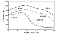
- Example 1 When applying an axial compressive force to the spring body, in Example 1 and Comparative Example 1, the spring body is elastically deformed in a direction of axial compression, and in Example 2 and Comparative Example 2, the spring body is axially deformed. Was not elastically deformed. In Comparative Example 3, only shot peening processing was performed.
- Example 1 As a result, as shown in FIG. 2, in Examples 1 and 2, the compressive residual stress applied to the radial outer end portion of the spring body 1e becomes maximum on the inner peripheral surface 1b where the depth is zero. It was confirmed that the value became lower toward the outer peripheral surface 1a side. In Comparative Examples 1 to 3, it was confirmed that the compressive residual stress was maximized at a predetermined depth position between the inner peripheral surface and the outer peripheral surface, and was not maximized on the inner peripheral surface having a depth of zero. Further, it was confirmed that the compressive residual stress on the inner peripheral surface 1b having a depth of zero was higher than that in Comparative Example 3 in both Examples 1 and 2, and was further increased after the shot peening process. At the same time, it was confirmed that Example 1 was higher than Example 2.
- the compressive residual stress is simultaneously applied to the plurality of disc springs 1 in a state where the plurality of disc springs 1 are provided in series in the axial direction. Further, the plurality of disc springs 1 are arranged so that the orientations of the plurality of disc springs 1 in the axial direction are the same.
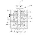
- the manufacturing apparatus 20 for carrying out the method for manufacturing a disc spring of the present embodiment includes a first support 21 and a second support 22.
- the first support 21 and the second support 22 are each rotatably provided around the central axis O.
- the first support 21 has a bottomed cylindrical main body portion 23 and a plurality of pressing members 24.
- the main body portion 23 has a cylindrical peripheral wall portion 23a and a disk-shaped bottom portion 23b connected to the lower end of the peripheral wall portion 23a.
- the main body 23 is arranged coaxially with the central axis O of the spring main body 1e.
- An annular lid (not shown) is detachably attached to the upper end of the peripheral wall portion 23a.
- a plurality of engaging holes (slits) 23c are formed in the peripheral wall portion 23a at intervals in the circumferential direction.
- the engagement hole 23c extends axially.
- the engaging hole 23c may be provided at the central portion of the peripheral wall portion 23a in the axial direction without extending to the end portion in the axial direction of the peripheral wall portion 23a.
- the engagement hole 23c may be provided so as to extend in the axial direction over the entire peripheral wall portion 23a.
- an engaging groove recessed from the inner peripheral surface of the peripheral wall portion 23a toward the outer peripheral surface side may be provided. By using the engaging groove, the strength of the peripheral wall portion 23a is improved.
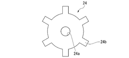
- the pressing member 24 is formed in a disk shape.
- the pressing member 24 is arranged coaxially with the central axis O of the spring body 1e.
- a plurality of pressing members 24 are provided at intervals in the axial direction.
- the pressing member 24 supports at least the outer end portion in the radial direction of the inner peripheral surface 1b of the spring body 1e.
- a hole 24a is formed in the radial center of the pressing member 24.
- the regulating portion 25 described later is inserted into the hole portion 24a of the pressing member 24 arranged on the bottom 23b side most, and the hole portion 24a of the other pressing member 24 is described later. 2
- the shaft portion 26 of the support 22 is inserted.
- a plurality of engaging claws 24b are provided on the outer peripheral edge of the pressing member 24 at intervals in the circumferential direction.
- the engaging claw 24b projects radially outward from the outer peripheral edge of the pressing member 24.
- the pressing member 24 is arranged inside the main body 23. At this time, the engaging claws 24b are respectively engaged with the engaging holes 23c.
- the pressing member 24 is attached to the main body portion 23 so as to be relatively non-rotatable and relatively movable in the axial direction. Therefore, the main body 23 and the pressing member 24 rotate integrally.
- the first support 21 is provided with a regulation unit 25.
- the regulating portion 25 is arranged coaxially with the central axis O.
- the regulating portion 25 projects from the radial center of the bottom portion 23b of the main body portion 23 toward the shaft portion 26.
- the second support 22 has a shaft portion 26 and a plurality of flat plate portions 27.
- the shaft portion 26 is arranged coaxially with the central axis O.
- the shaft portion 26 is inserted inside the spring body 1e.
- a plurality of engaging grooves 26a are formed on the outer peripheral surface of the shaft portion 26 at intervals in the circumferential direction.
- the engaging groove 26a extends axially.
- the flat plate portion 27 is formed in a disk shape.
- the flat plate portion 27 is arranged coaxially with the central axis O of the spring body 1e.
- a plurality of flat plate portions 27 are provided at intervals in the axial direction.
- the flat plate portion 27 supports at least the inner end portion in the radial direction of the outer peripheral surface 1a of the spring body 1e.
- a hole portion 27a is formed in the radial center of the flat plate portion 27.
- a plurality of engaging claws 27b are provided on the peripheral surface of the hole portion 27a at intervals in the circumferential direction.
- the engaging claw 27b projects radially inward from the peripheral surface of the hole 27a.
- a shaft portion 26 is inserted through the hole portion 27a.
- the engaging claws 27b are respectively engaged with the engaging grooves 26a.
- the flat plate portion 27 is attached to the shaft portion 26 so as to be relatively non-rotatable and relatively movable in the axial direction. Therefore, the shaft portion 26 and the flat plate portion 27 rotate integrally.
- the flat plate portion 27 is provided with a detent member 28.
- the detent member 28 regulates the rotational movement of the spring body 1e around the central axis O with respect to the second support 22.
- the detent member 28 is provided on the front and back surfaces of the flat plate portion 27 facing the outer peripheral surface 1a of the spring body 1e (in the illustrated example, the surface on the bottom portion 23b side).
- a plurality of inner claws are provided on the inner peripheral edge of the spring body 1e at intervals in the circumferential direction, and the detent member 28 is arranged between the inner claws adjacent to each other in the circumferential direction.
- a configuration may be adopted in which the radial inner end portion of the spring body 1e is sandwiched from both sides in the axial direction as the detent member 28.
- the rotational movement of the spring body 1e with respect to the second support 22 may be restricted by the frictional force generated between the spring body 1e and the flat plate portion 27 without providing the detent member 28.
- the pressing member 24 and the flat plate portion 27 are alternately inserted into the shaft portion 26.
- the pressing member 24 and the flat plate portion 27 are arranged at intervals in the axial direction.
- the spring body 1e is arranged between the pressing member 24 and the flat plate portion 27.
- the spring body 1e is supported from both sides in the axial direction by the pressing member 24 and the flat plate portion 27.
- the pressing member 24 supports at least the outer end portion in the radial direction of the inner peripheral surface 1b of the spring body 1e
- the flat plate portion 27 supports at least the radial outer end portion of the outer peripheral surface 1a of the spring body 1e. Supports the inner end of the.
- the pressing member 24 and the flat plate portion 27 are movable in the axial direction.
- the pressing member 24 and the flat plate portion 27 are provided so as to be relatively close to each other in the axial direction.
- the surface roughness of the portion of the pressing member 24 that comes into contact with the flat plate portion 27 is made smaller than the surface roughness of the other portions.
- the surface roughness of the portion of the flat plate portion 27 that comes into contact with the pressing member 24 may be smaller than the surface roughness of the other portion.
- a thrust bearing may be provided between the pressing member 24 and the flat plate portion 27.
- the restricting portion 25 and the shaft portion 26 come into contact with each other in the axial direction, and the first support 21 and the second support 22 , Regulate further axial approach movement. That is, the shaft portion 26 also functions as a regulating portion.
- the disc spring 1 is subjected to shot peening processing.
- the first support 21 and the second support 22 applying an axial compressive force to the spring body 1e
- the first support 21 and the spring body 1e are in sliding contact with each other and the central axis O. Relative rotation around.
- compressive residual stress is applied to at least the outer end portion in the radial direction of the inner peripheral surface 1b of the spring body 1e over the entire length in the circumferential direction.
- the first support 21 and the second support 22 are moved closer to each other in the axial direction, and the spring body 1e and the restricting portion 25 of the first support 21 are moved.
- the shaft portion 26 of the second support 22 is brought into contact with each other in the axial direction.
- the spring body 1e is elastically deformed by a predetermined amount in the direction of compression in the axial direction, and a tensile stress is generated on the inner peripheral surface 1b of the spring body 1e.
- first support 21 and the second support 22 rotate the first support 21 in one direction along the central axis O while applying a compressive force in the axial direction to the spring body 1e. 2
- the support 22 is rotated in the other direction along the central axis O. Since the detent member 28 regulates the rotational movement of the spring body 1e around the central axis O with respect to the second support 22, the spring body 1e also follows the center axis O as the second support 22 rotates. Rotate in the other direction. As a result, the pressing member 24 slides on the inner peripheral surface 1b of the spring body 1e in the circumferential direction.
- the first support 21 that supports at least the outer end portion in the radial direction of the inner peripheral surface 1b of the spring main body 1e is used to support the spring main body 1e in the axial direction.
- a compressive force at least in the radial direction of the inner peripheral surface 1b of the spring body 1e.
- a compressive residual stress is applied to the outer end. Therefore, the compressive residual stress at the radial outer end of the spring body 1e is maximized on the inner peripheral surface 1b where the highest tensile stress is generated when the disc spring 1 is used, and is directed toward the outer peripheral surface 1a. It is possible to surely obtain the disc spring 1 provided so as to be lowered accordingly.
- the compression residual stress is applied to the plurality of disc springs 1 at the same time, the compression is applied over the entire length in the circumferential direction at the radial outer end portion of the spring body 1e.
- a plurality of disc springs 1 having a residual stress applied as described above can be efficiently obtained.
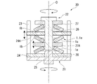
- the compressive residual stress is simultaneously applied to the plurality of disc springs 1 in a state where the plurality of disc springs 1 are provided in series in the axial direction. Further, in the present embodiment, the plurality of disc springs 1 are arranged so that the axial directions of the plurality of disc springs 1 are opposite to each other.
- the manufacturing apparatus 30 for carrying out the manufacturing method of the disc spring of this embodiment will be described.
- the manufacturing apparatus 30 among the plurality of pressing members 24 of the first support 21, there are two pressing members 24A other than the pressing member 24 arranged on the side closest to the bottom 23b. It is configured to support the disc spring 1.
- two disc springs 1 whose axial directions are opposite to each other are arranged so as to sandwich the pressing member 24A in the axial direction.
- these two disc springs 1 are arranged so that the inner peripheral surface 1b of the spring body 1e faces the pressing member 24A.
- the pressing member 24A supports at least the outer end portion in the radial direction of the inner peripheral surface 1b of the spring body 1e of these two disc springs 1 on both sides of the pressing member 24A.
- the flat plate portion 27A other than the flat plate portion 27 arranged on the side farthest from the bottom portion 23b is configured to support the two disc springs 1.
- two disc springs 1 whose axial directions are opposite to each other are arranged so as to sandwich the flat plate portion 27A in the axial direction. At this time, these two disc springs 1 are arranged so that the outer peripheral surface 1a of the spring body 1e faces the flat plate portion 27A.
- the flat plate portion 27A supports at least the inner end portion in the radial direction of the outer peripheral surface 1a of the spring main body 1e of these two disc springs 1 on both sides of the flat plate portion 27A.
- the detent member 28 is provided on both sides of the flat plate portion 27A.
- the method of manufacturing the disc spring using the manufacturing device 30 is the same as that of the second embodiment. That is, with the first support 21 and the second support 22 applying an axial compressive force to the spring body 1e, the first support 21 and the spring body 1e are in sliding contact with each other and rotate around the central axis O. Relative rotation to. As a result, compressive residual stress is applied to at least the outer end portion in the radial direction of the inner peripheral surface 1b of the spring body 1e over the entire length in the circumferential direction.
- the compressive residual stress at the radial outer end of the spring body 1e is maximized on the inner peripheral surface 1b where the highest tensile stress is generated when the disc spring 1 is used, and is directed toward the outer peripheral surface 1a. It is possible to surely obtain the disc spring 1 provided so as to be lowered accordingly. Further, since the compressive residual stress is applied to the plurality of disc springs 1 at the same time, the compressive residual stress is applied to the plurality of disc springs 1e over the entire length in the circumferential direction at the radial outer end portion of the spring body 1e as described above. Belleville spring 1 can be obtained efficiently.
- the two disc springs 1 are supported by one pressing member 24 (24A) and one flat plate portion 27 (27A), the number of parts of the pressing member 24 and the flat plate portion 27 is reduced. be able to. Therefore, it is possible to simplify the configurations of the first support 21 and the second support 22. In addition, the axial dimension of the manufacturing apparatus 30 can be shortened.
- the compressive residual stress is simultaneously applied to the plurality of disc springs 1 in a state where the plurality of disc springs 1 are arranged on the same plane in the same axial direction.
- the manufacturing apparatus 40 for carrying out the manufacturing method of the disc spring of this embodiment will be described.
- the main body 23 of the first support 21 is arranged coaxially with the rotation axis Og different from the central axis O of the spring main body 1e.
- the plurality of disc springs 1 are arranged on the same plane at intervals in the circumferential direction around the rotation axis Og.
- a shaft portion 26, a flat plate portion 27, and a pressing member 24 are provided for each of the plurality of disc springs 1.
- the shaft portion 26, the flat plate portion 27, and the pressing member 24 are arranged coaxially with the central axis O of each disc spring 1.
- the pressing member 24 is provided for each of the disc springs 1, but one pressing member 24 may be provided for the entire plurality of disc springs 1.
- the second support 22 further includes a rotation shaft portion 42 arranged coaxially with the rotation axis Og.
- a drive gear 41A is provided at the upper end of the rotary shaft portion 42.
- a driven gear 41B meshed with the drive gear 41A is provided at the upper end portion of the shaft portion 26.
- the first support 21 does not rotate.
- the pressing member 24 is non-rotatably fixed to the bottom portion 23b of the main body portion 23.
- the regulation unit 25 is arranged coaxially with the rotation axis Og.
- the regulating portion 25 is provided so as to project from the radial center of the bottom portion 23b toward the rotating shaft portion 42.
- the disc spring 1 is subjected to shot peening processing.
- the first support 21 and the second support 22 applying an axial compressive force to the spring body 1e
- the first support 21 and the spring body 1e are in sliding contact with each other and the central axis O. Relative rotation around.
- compressive residual stress is applied to at least the outer end portion in the radial direction of the inner peripheral surface 1b of the spring body 1e over the entire length in the circumferential direction.
- the first support 21 and the second support 22 are moved closer to each other in the axial direction, and the spring body 1e and the restricting portion 25 of the first support 21 are moved.
- the rotating shaft portion 42 of the second support 22 is brought into contact with each other in the axial direction.
- the spring body 1e is elastically deformed by a predetermined amount in the direction of compression in the axial direction, and a tensile stress is generated on the inner peripheral surface 1b of the spring body 1e.
- the rotating shaft portion 42 is rotated in one direction along the rotation axis Og while the spring main body 1e is subjected to an axial compressive force by the first support 21 and the second support 22.
- the shaft portion 26 rotates in the other direction along the central axis O.
- the spring body 1e also rotates in the other direction along the central axis O.
- the first support 21 that supports at least the outer end portion in the radial direction of the inner peripheral surface 1b of the spring main body 1e is used to support the spring main body 1e in the axial direction.
- a compressive force at least in the radial direction of the inner peripheral surface 1b of the spring body 1e.
- a compressive residual stress is applied to the outer end. Therefore, the compressive residual stress at the radial outer end of the spring body 1e is maximized on the inner peripheral surface 1b where the highest tensile stress is generated when the disc spring 1 is used, and is directed toward the outer peripheral surface 1a. It is possible to surely obtain the disc spring 1 provided so as to be lowered accordingly.
- the compression residual stress is applied to the plurality of disc springs 1 at the same time, the compression is applied over the entire length in the circumferential direction at the radial outer end portion of the spring body 1e.
- a plurality of disc springs 1 having a residual stress applied as described above can be efficiently obtained.
- the driven gear 41B of the shaft portion 26 is provided, the driven gear 24 may be provided on the pressing member 24 side to rotate the pressing member 24 without rotating the shaft portion 26 (spring body 1e). Even in this case, the first support 21 and the spring body 1e can be relatively rotated around the central axis O while being in sliding contact with each other.
- the outer peripheral edge 1c of the spring body 1e is provided with an outer claw that projects outward in the radial direction, and the outer peripheral surface 1a and the inner peripheral surface 1b of the spring body 1e are flush with the front and back surfaces of the outer claw.
- the first support 11 may be provided with a restricting portion that abuts on the radial outer end portion of the outer claw. In this case, compressive residual stress can be easily applied to at least the outer end portion in the radial direction of the inner peripheral surface 1b of the spring body 1e.
- the second support 12 may be provided with a detent member that regulates the rotational movement of the spring body 1e around the central axis O with respect to the second support 12.
- a detent member that regulates the rotational movement of the spring body 1e around the central axis O with respect to the second support 12.
- a detent member is positioned between the inner claws adjacent to each other in the circumferential direction to form a spring.
- the radial inner ends of the spring main body 1e may be sandwiched from both sides in the axial direction by the detent member.
- the spring body 1e when an axial compressive force is applied to the spring body 1e by using the first supports 11 and 21, the spring body 1e does not have to be elastically deformed in the axial direction.
- the second supports 12 and 22 may support the outer peripheral surface 1a of the spring body 1e.
- At least one of the first support 11 and the second support 12 may be provided so as to be relatively rotatable about the central axis O with respect to any one of the other.
- the first support 11 and the second support 12 are rotatably provided around the central axis O
- the first support 11 and the spring body 1e are brought into sliding contact with each other
- the first support The second support 12 may be rotated in the other direction along the central axis O while the body 11 is rotated in one direction along the central axis O.
- the first support 11 and the second support 12 may be rotated in the same direction along the central axis O with a speed difference.
- the first support 11 and the spring body 1e are brought into sliding contact with each other, the first support 11 may not be rotated around the central axis O, but only the second support 12 may be rotated around the central axis O. ..
- At least one of the first support 21 and the second support 22 may be provided so as to be relatively rotatable about the central axis O with respect to any of the other. That is, when the first support 21 and the spring body 1e are in sliding contact with each other, the first support 21 may not be rotated around the central axis O, but only the second support 22 may be rotated around the central axis O. However, the second support 22 may not be rotated around the central axis O, but only the first support 21 may be rotated around the central axis O. Further, the first support 21 and the second support 22 may be rotated in the same direction along the central axis O with a speed difference.
- a plurality of pressing protrusions 13 of the first embodiment may be provided instead of the disk-shaped pressing member 24.
- the compressive residual stress at the radial outer end of the spring body is maximum on the inner peripheral surface where the highest tensile stress is generated when the disc spring is used, and toward the outer peripheral surface side. It is possible to obtain a disc spring imparted so as to be lowered accordingly.
Abstract
This disc spring manufacturing method is a method for manufacturing a disc spring that includes a spring body (1e) which is formed in a ring shape and which comprises: an outer circumferential surface (1a) facing outward in the radial direction; an inner circumferential surface (1b) facing inward in the radial direction; an outer circumferential edge (1c) being an outer end surface in the radial direction; and an inner circumferential edge (1d) being an inner end surface in the radial direction. In a state where a support body (11) is used for supporting at least an outer end portion in the radial direction of the inner circumferential surface (1b), and where a compressive force in the axial direction along the center axis line of the spring body is applied to the spring body, the support body and the spring body are made to rotate relatively around the center axis line while being in sliding contact with each other, such that a compressive residual stress is applied to at least the outer end portion in the radial direction of the inner circumferential surface.
Description
本発明は、皿ばねの製造方法、および皿ばねに関するものである。
本願は、2020年10月14日に、日本に出願された特願2020-173168号に基づき優先権を主張し、その内容をここに援用する。 The present invention relates to a method for manufacturing a Belleville spring and a Belleville spring.
This application claims priority based on Japanese Patent Application No. 2020-173168 filed in Japan on October 14, 2020, the contents of which are incorporated herein by reference.
従来から、径方向の外側を向く外周面と、径方向の内側を向く内周面と、径方向の外側の端面である外周縁と、径方向の内側の端面である内周縁と、有して環状に形成されたばね本体を有する皿ばねの製造方法として、例えば下記特許文献1に示される方法が知られている。特許文献1に示される方法では、回転可能に支持されたボールを、ばね本体の内周面に対して押付けた状態で回転させつつ移動させることで、ばね本体に圧縮残留応力を付与する。
Conventionally, it has an outer peripheral surface facing outward in the radial direction, an inner peripheral surface facing inward in the radial direction, an outer peripheral edge which is an outer end surface in the radial direction, and an inner peripheral edge which is an inner end surface in the radial direction. As a method for manufacturing a disc spring having a spring body formed in an annular shape, for example, the method shown in Patent Document 1 below is known. In the method shown in Patent Document 1, a ball rotatably supported is moved while being pressed against the inner peripheral surface of the spring body while being rotated to apply compressive residual stress to the spring body.
従来の皿ばねの製造方法では、ばね本体に付与される圧縮残留応力が、内周面と外周面との間の所定の深さ位置で最大となり、使用時に最も高い引張応力が生ずる内周面では最大にならず、皿ばねの耐久性を向上させることが困難である可能性がある。
In the conventional method of manufacturing a disc spring, the compressive residual stress applied to the spring body is maximized at a predetermined depth position between the inner peripheral surface and the outer peripheral surface, and the inner peripheral surface where the highest tensile stress is generated during use. It may not be maximized and it may be difficult to improve the durability of the disc spring.
この発明は、このような事情を考慮してなされたもので、ばね本体の径方向の外端部における周方向の全長にわたって、圧縮残留応力が、内周面で最大となり、外周面側に向かうに従い低くなるように付与された皿ばねを得ることができる皿ばねの製造方法、および皿ばねを提供することを目的とする。
The present invention has been made in consideration of such circumstances, and the compressive residual stress is maximized on the inner peripheral surface and toward the outer peripheral surface side over the entire length in the circumferential direction at the radial outer end of the spring body. It is an object of the present invention to provide a method for manufacturing a Belleville spring, which can obtain a Belleville spring applied so as to be lowered according to the method, and to provide a Belleville spring.
本発明の一態様の皿ばねの製造方法は、径方向の外側を向く外周面と、径方向の内側を向く内周面と、径方向の外側の端面である外周縁と、径方向の内側の端面である内周縁と、を有して環状に形成されたばね本体を有する皿ばねの製造方法であって、前記内周面のうち、少なくとも径方向の外端部を支持する支持体を用いて、前記ばね本体に、前記ばね本体の中心軸線に沿う軸方向の圧縮力を付与した状態で、前記支持体および前記ばね本体を、互いに摺接させつつ前記中心軸線回りに相対回転させることで、前記内周面のうち、少なくとも径方向の外端部に圧縮残留応力を付与する。
The method for manufacturing a disc spring according to one aspect of the present invention includes an outer peripheral surface facing outward in the radial direction, an inner peripheral surface facing inward in the radial direction, an outer peripheral edge which is an outer end surface in the radial direction, and an inner peripheral surface in the radial direction. A method for manufacturing a disc spring having an inner peripheral edge which is an end surface of the spring body and a spring body formed in an annular shape, using a support which supports at least the outer end portion in the radial direction of the inner peripheral surface. By applying a compressive force in the axial direction along the central axis of the spring body to the spring body, the support and the spring body are relatively rotated around the central axis while being in sliding contact with each other. , At least the outer end portion in the radial direction of the inner peripheral surface is subjected to compressive residual stress.
上記態様によれば、ばね本体の内周面のうち、少なくとも径方向の外端部を支持する支持体を用いて、ばね本体に前記軸方向の圧縮力を付与した状態で、支持体およびばね本体を、互いに摺接させつつ前記中心軸線回りに相対回転させることで、ばね本体の内周面のうち、少なくとも径方向の外端部に圧縮残留応力を付与する。
したがって、ばね本体の径方向の外端部における前記中心軸線回りに沿う周方向の全長にわたって、圧縮残留応力が、皿ばねの使用時に最も高い引張応力が生ずる内周面で最大となり、外周面側に向かうに従い低くなるように付与された皿ばねを確実に得ることができる。 According to the above aspect, the support and the spring are provided with the axial compressive force applied to the spring body by using the support that supports at least the radial outer end portion of the inner peripheral surface of the spring body. By rotating the main bodies relative to each other around the central axis while sliding them against each other, compressive residual stress is applied to at least the outer end portion in the radial direction of the inner peripheral surface of the spring main body.
Therefore, the compressive residual stress at the radial outer end of the spring body is maximum on the inner peripheral surface where the highest tensile stress is generated when the disc spring is used, and is on the outer peripheral surface side, over the entire length in the circumferential direction along the central axis. It is possible to surely obtain a disc spring imparted so as to become lower toward.
前記ばね本体に、前記支持体を用いて前記軸方向の圧縮力を付与する際、前記ばね本体を前記軸方向に弾性変形させてもよい。
When applying a compressive force in the axial direction to the spring body by using the support, the spring body may be elastically deformed in the axial direction.
この場合、ばね本体に、支持体を用いて前記軸方向の圧縮力を付与する際、ばね本体を前記軸方向に弾性変形させて、ばね本体の内周面のうちの少なくとも径方向の外端部を引張する。これにより、ばね本体の内周面における径方向の外端部に、高い圧縮残留応力を確実に付与することができる。
In this case, when a support is used to apply a compressive force in the axial direction to the spring body, the spring body is elastically deformed in the axial direction to at least the outer end of the inner peripheral surface of the spring body in the radial direction. Pull the part. As a result, a high compressive residual stress can be reliably applied to the outer end portion in the radial direction on the inner peripheral surface of the spring body.
前記支持体は、周方向に間隔をあけて設けられた複数の押付突起を備え、前記内周面のうち、少なくとも径方向の外端部は、複数の前記押付突起に支持されてもよい。
The support includes a plurality of pressing protrusions provided at intervals in the circumferential direction, and at least the outer end portion in the radial direction of the inner peripheral surface may be supported by the plurality of pressing protrusions.
この場合、ばね本体の内周面のうち、少なくとも径方向の外端部が、周方向に間隔をあけて設けられた複数の押付突起に支持されている。これにより、支持体からばね本体の内周面に加えられる接触圧力を高めることが可能になり、ばね本体の内周面における径方向の外端部に、高い圧縮残留応力を確実に付与することができる。
In this case, at least the outer end portion in the radial direction of the inner peripheral surface of the spring body is supported by a plurality of pressing protrusions provided at intervals in the circumferential direction. This makes it possible to increase the contact pressure applied from the support to the inner peripheral surface of the spring body, and to reliably apply high compressive residual stress to the radial outer end of the inner peripheral surface of the spring body. Can be done.
前記軸方向に沿い、かつ前記中心軸線を通る縦断面視において、前記軸方向で互いに対向する前記内周面、および前記押付突起の押付面はそれぞれ、前記中心軸線に直交する水平面に対して同じ向きに傾斜してもよい。
In a vertical cross-sectional view along the axial direction and passing through the central axis, the inner peripheral surfaces facing each other in the axial direction and the pressing surfaces of the pressing protrusions are the same with respect to the horizontal plane orthogonal to the central axis, respectively. It may be tilted in the direction.
この場合、前記縦断面視において、前記軸方向で互いに対向するばね本体の内周面、および押付突起の押付面がそれぞれ、水平面に対して同じ向きに傾斜している。これにより、ばね本体の内周面に圧縮残留応力を付与するときに、ばね本体において内周面と外周縁とを接続する角部分から押付面に過度に大きな負荷が加えられるのを抑制することができるとともに、圧縮残留応力をばね本体の内周面に径方向の幅を持たせて容易に付与することができる。
In this case, in the vertical cross-sectional view, the inner peripheral surface of the spring body facing each other in the axial direction and the pressing surface of the pressing protrusion are inclined in the same direction with respect to the horizontal plane, respectively. As a result, when compressive residual stress is applied to the inner peripheral surface of the spring body, it is possible to prevent an excessively large load from being applied to the pressing surface from the corner portion connecting the inner peripheral surface and the outer peripheral edge of the spring body. In addition, compressive residual stress can be easily applied to the inner peripheral surface of the spring body with a radial width.
前記内周面のうち、径方向の外端部より径方向の内側に位置する部分と、前記押付面と、の間に、前記軸方向の隙間を設けた状態で、前記ばね本体に前記軸方向の圧縮力を付与する。
The shaft of the spring body is provided with an axial gap between the inner peripheral surface, which is located inward in the radial direction from the outer end portion in the radial direction, and the pressing surface. Applying compressive force in the direction.
この場合、ばね本体の内周面のうち、径方向の外端部より径方向の内側に位置する部分と、押付面と、の間に、前記軸方向の隙間を設けた状態で、ばね本体に前記軸方向の圧縮力を付与する。これにより、支持体およびばね本体を、互いに摺接させつつ前記中心軸線回りに相対回転させるときに、押付面とばね本体の内周面との間に生ずる摺動抵抗を抑制することができるとともに、圧縮残留応力を、例えばばね本体の内周面における径方向の外端部に局所的に付与することができる。また、ばね本体を前記軸方向に弾性変形させる場合には、ばね本体の前記軸方向の圧縮変形量を調整することが可能になり、ばね本体の内周面のうち、少なくとも径方向の外端部に付与する圧縮残留応力を容易に調整することができる。
In this case, the spring main body is provided with an axial gap between the inner peripheral surface of the spring main body, the portion located inside the radial direction from the outer end portion in the radial direction, and the pressing surface. Is given a compressive force in the axial direction. As a result, it is possible to suppress the sliding resistance generated between the pressing surface and the inner peripheral surface of the spring body when the support and the spring body are relatively rotated around the central axis while being in sliding contact with each other. , Compressive residual stress can be applied locally, for example, to the radial outer end of the inner peripheral surface of the spring body. Further, when the spring body is elastically deformed in the axial direction, the amount of compression deformation in the axial direction of the spring body can be adjusted, and at least the outer end in the radial direction of the inner peripheral surface of the spring body. The compressive residual stress applied to the portion can be easily adjusted.
前記押付突起のうち、前記軸方向で前記内周面と対向する押付面は、径方向から見て前記軸方向に突の曲線状を呈してもよい。
Of the pressing protrusions, the pressing surface facing the inner peripheral surface in the axial direction may have a curved shape of protrusion in the axial direction when viewed from the radial direction.
この場合、押付面が、径方向から見て前記軸方向に突の曲線状を呈する。これにより、ばね本体の内周面に圧縮残留応力を付与するときに、押付面およびばね本体の内周面に加えられる負荷を抑えつつ、押付面からばね本体の内周面に加えられる接触圧力を確実に高めることができる。
In this case, the pressing surface exhibits a protruding curved shape in the axial direction when viewed from the radial direction. As a result, when compressive residual stress is applied to the inner peripheral surface of the spring body, the contact pressure applied from the pressing surface to the inner peripheral surface of the spring body while suppressing the load applied to the pressing surface and the inner peripheral surface of the spring body. Can be surely increased.
複数の前記皿ばねを前記軸方向に直列に設けた状態で、複数の前記皿ばねに同時に前記圧縮残留応力を付与してもよい。
The compression residual stress may be applied to the plurality of disc springs at the same time in a state where the plurality of disc springs are provided in series in the axial direction.
この場合、複数の皿ばねに同時に前記圧縮残留応力を付与する。これにより、ばね本体の径方向の外端部における周方向の全長にわたって、前記圧縮残留応力が、前述のように付与された複数の皿ばねを効率よく得ることができる。
In this case, the compressive residual stress is applied to a plurality of disc springs at the same time. Thereby, a plurality of disc springs to which the compressive residual stress is applied as described above can be efficiently obtained over the entire length in the circumferential direction at the radial outer end portion of the spring body.
複数の前記皿ばねを、前記軸方向の同じ向きに向けて同一平面上に複数並べた状態で、複数の前記皿ばねに同時に前記圧縮残留応力を付与してもよい。
In a state where a plurality of the disc springs are arranged on the same plane in the same direction in the axial direction, the compressive residual stress may be applied to the plurality of disc springs at the same time.
この場合、複数の皿ばねに同時に前記圧縮残留応力を付与する。これにより、ばね本体の径方向の外端部における周方向の全長にわたって、前記圧縮残留応力が、前述のように付与された複数の皿ばねを効率よく得ることができる。
In this case, the compressive residual stress is applied to a plurality of disc springs at the same time. Thereby, a plurality of disc springs to which the compressive residual stress is applied as described above can be efficiently obtained over the entire length in the circumferential direction at the radial outer end portion of the spring body.
本発明の一態様の皿ばねは、径方向の外側を向く外周面と、径方向の内側を向く内周面と、径方向の外側の端面である外周縁と、径方向の内側の端面である内周縁と、を有して環状に形成されたばね本体を有し、前記内周面のうち、少なくとも径方向の外端部に、前記ばね本体の中心軸線回りに沿う周方向の全長にわたって、圧縮残留応力が付与され、前記圧縮残留応力は、前記内周面において最大となり、前記外周面側に向かうに従い低くなっており、前記内周面のうち、前記圧縮残留応力が付与されている部分の表面粗さは、これより径方向の内側に位置する部分の表面粗さより小さくなっている。
The countersunk spring of one aspect of the present invention has an outer peripheral surface facing outward in the radial direction, an inner peripheral surface facing inward in the radial direction, an outer peripheral edge which is an outer end surface in the radial direction, and an inner end surface in the radial direction. It has a spring body formed in an annular shape with an inner peripheral edge, and at least at the outer end portion in the radial direction of the inner peripheral surface, over the entire length in the circumferential direction along the central axis of the spring body. The compressive residual stress is applied, and the compressive residual stress becomes maximum on the inner peripheral surface and decreases toward the outer peripheral surface side, and the portion of the inner peripheral surface to which the compressive residual stress is applied. The surface roughness of is smaller than the surface roughness of the portion located inside in the radial direction.
上記態様によれば、ばね本体の径方向の外端部における周方向の全長にわたって、圧縮残留応力が、皿ばねの使用時に最も高い引張応力が生ずる内周面で最大となり、外周面側に向かうに従い低くなるように付与されているので、皿ばねの耐久性を向上させることができる。
ばね本体の内周面において、皿ばねの使用時に最も高い引張応力が生ずる径方向の外端部の表面粗さが、前記圧縮残留応力が付与されている部分より径方向の内側に位置する部分の表面粗さより小さくなっている。これにより、皿ばねの使用時に、ばね本体の内周面における径方向の外端部に、例えば傷および表面粗さのばらつき等に起因して応力集中箇所が生ずること、並びに、ばね本体の内周面における径方向の外端部を支持する部材が損傷しやすくなること、をそれぞれ抑制することができる。 According to the above aspect, the compressive residual stress at the radial outer end of the spring body is maximum on the inner peripheral surface where the highest tensile stress is generated when the disc spring is used, and is directed toward the outer peripheral surface side. Since it is given so as to be lowered according to the amount, the durability of the disc spring can be improved.
On the inner peripheral surface of the spring body, the surface roughness of the outer end portion in the radial direction where the highest tensile stress is generated when the disc spring is used is located inside the portion where the compressive residual stress is applied. It is smaller than the surface roughness of. As a result, when the disc spring is used, stress concentration points are generated at the outer end portion in the radial direction on the inner peripheral surface of the spring body due to, for example, scratches and variations in surface roughness, and the inside of the spring body. It is possible to prevent the members supporting the radial outer end portion on the peripheral surface from being easily damaged.
本発明の別の一態様の皿ばねは、径方向の外側を向く外周面と、径方向の内側を向く内周面と、径方向の外側の端面である外周縁と、径方向の内側の端面である内周縁と、を有して環状に形成されたばね本体を有し、前記内周面のうち、少なくとも径方向の外端部に、前記ばね本体の中心軸線回りに沿う周方向の全長にわたって、圧縮残留応力が付与され、前記圧縮残留応力は、前記内周面において最大となり、前記外周面側に向かうに従い低くなっており、前記内周面のうち、前記圧縮残留応力が付与されている部分の硬度は、これより径方向の内側に位置する部分の硬度より高くなっている。
Another aspect of the present invention is a countersunk spring having an outer peripheral surface facing outward in the radial direction, an inner peripheral surface facing inward in the radial direction, an outer peripheral edge which is an outer end surface in the radial direction, and an inner peripheral surface in the radial direction. It has a spring body formed in an annular shape with an inner peripheral edge which is an end face, and has an outer end portion in at least a radial direction of the inner peripheral surface, and has a total length in the circumferential direction along the central axis of the spring body. The compressive residual stress is applied to the inner peripheral surface, and the compressive residual stress becomes maximum on the inner peripheral surface and decreases toward the outer peripheral surface side, and the compressive residual stress is applied to the inner peripheral surface. The hardness of the portion is higher than the hardness of the portion located inside in the radial direction.
上記態様によれば、ばね本体の径方向の外端部における周方向の全長にわたって、圧縮残留応力が、皿ばねの使用時に最も高い引張応力が生ずる内周面で最大となり、外周面側に向かうに従い低くなるように付与されているので、皿ばねの耐久性を向上させることができる。
ばね本体の内周面において、皿ばねの使用時に最も高い引張応力が生ずる径方向の外端部の硬度が、前記圧縮残留応力が付与されている部分より径方向の内側に位置する部分の硬度より高くなっている。これにより、皿ばねの使用時に、ばね本体の内周面における径方向の外端部に、摩耗が生じたり、例えば傷等に起因して応力集中箇所が生じたりするのを抑制することができる。 According to the above aspect, the compressive residual stress at the radial outer end of the spring body is maximum on the inner peripheral surface where the highest tensile stress is generated when the disc spring is used, and is directed toward the outer peripheral surface side. Since it is given so as to be lowered according to the amount, the durability of the disc spring can be improved.
On the inner peripheral surface of the spring body, the hardness of the outer end portion in the radial direction where the highest tensile stress is generated when the disc spring is used is the hardness of the portion located inside in the radial direction from the portion to which the compressive residual stress is applied. It's getting higher. As a result, when the disc spring is used, it is possible to prevent wear from occurring at the outer end portion in the radial direction on the inner peripheral surface of the spring body, and from the occurrence of stress concentration points due to, for example, scratches. ..
この構成において、前記内周面のうち、前記圧縮残留応力が付与されている部分の表面粗さは、これより径方向の内側に位置する部分の表面粗さより小さくなってもよい。
In this configuration, the surface roughness of the portion of the inner peripheral surface to which the compressive residual stress is applied may be smaller than the surface roughness of the portion located inside in the radial direction.
この場合、ばね本体の内周面において、皿ばねの使用時に最も高い引張応力が生ずる径方向の外端部の表面粗さが、前記圧縮残留応力が付与されている部分より径方向の内側に位置する部分の表面粗さより小さくなっている。これにより、皿ばねの使用時に、ばね本体の内周面における径方向の外端部に、例えば傷および表面粗さのばらつき等に起因して応力集中箇所が生ずること、並びに、ばね本体の内周面における径方向の外端部を支持する部材が損傷しやすくなること、をそれぞれ抑制することができる。
In this case, on the inner peripheral surface of the spring body, the surface roughness of the radial outer end portion where the highest tensile stress is generated when the disc spring is used is radially inward from the portion to which the compressive residual stress is applied. It is smaller than the surface roughness of the located part. As a result, when the disc spring is used, stress concentration points are generated at the outer end portion in the radial direction on the inner peripheral surface of the spring body due to, for example, scratches and variations in surface roughness, and the inside of the spring body. It is possible to prevent the members supporting the radial outer end portion on the peripheral surface from being easily damaged.
この発明によれば、ばね本体の径方向の外端部における周方向の全長にわたって、圧縮残留応力が、皿ばねの使用時に最も高い引張応力が生ずる内周面で最大となり、外周面側に向かうに従い低くなるように付与された皿ばねを得ることができる。
According to the present invention, the compressive residual stress at the radial outer end of the spring body is maximum on the inner peripheral surface where the highest tensile stress is generated when the disc spring is used, and toward the outer peripheral surface side. It is possible to obtain a disc spring imparted so as to be lowered accordingly.
(第1実施形態)
以下、本発明に係る皿ばねの製造方法、および皿ばねの第1実施形態を、図1を参照しながら説明する。 (First Embodiment)
Hereinafter, a method for manufacturing a disc spring according to the present invention and a first embodiment of the disc spring will be described with reference to FIG.
以下、本発明に係る皿ばねの製造方法、および皿ばねの第1実施形態を、図1を参照しながら説明する。 (First Embodiment)
Hereinafter, a method for manufacturing a disc spring according to the present invention and a first embodiment of the disc spring will be described with reference to FIG.
皿ばね1は、金属製の板材が加工されて形成される。皿ばね1のばね本体1eは、中心軸線Oを有する環状に形成されている。
以下、中心軸線Oに沿う方向を軸方向といい、軸方向から見て、中心軸線Oに交差する方向を径方向といい、中心軸線O回りに周回する方向を周方向という。 Thedisc spring 1 is formed by processing a metal plate material. The spring body 1e of the disc spring 1 is formed in an annular shape having a central axis O.
Hereinafter, the direction along the central axis O is referred to as an axial direction, the direction intersecting the central axis O when viewed from the axial direction is referred to as a radial direction, and the direction orbiting around the central axis O is referred to as a circumferential direction.
以下、中心軸線Oに沿う方向を軸方向といい、軸方向から見て、中心軸線Oに交差する方向を径方向といい、中心軸線O回りに周回する方向を周方向という。 The
Hereinafter, the direction along the central axis O is referred to as an axial direction, the direction intersecting the central axis O when viewed from the axial direction is referred to as a radial direction, and the direction orbiting around the central axis O is referred to as a circumferential direction.
ばね本体1eは、外周面1a、内周面1b、外周縁1c、および内周縁1dを有している。
外周面1aは径方向の外側を向き、内周面1bは径方向の内側を向いている。外周面1aおよび内周面1bは、中心軸線Oに対して傾斜している。ばね本体1eは、軸方向に開口した傘形状、若しくはすり鉢形状に形成されている。
外周縁1cは、ばね本体1eにおける径方向の外側の端面とされ、内周縁1dは、ばね本体1eにおける径方向の内側の端面となっている。
なお、皿ばねとして、外周縁1cから径方向の外側に向けて突出した外爪、若しくは内周縁1dから径方向の内側に向けて突出した内爪が設けられた構成を採用してもよい。 Thespring body 1e has an outer peripheral surface 1a, an inner peripheral surface 1b, an outer peripheral edge 1c, and an inner peripheral edge 1d.
The outerperipheral surface 1a faces the outer side in the radial direction, and the inner peripheral surface 1b faces the inner side in the radial direction. The outer peripheral surface 1a and the inner peripheral surface 1b are inclined with respect to the central axis O. The spring body 1e is formed in the shape of an umbrella or a mortar that opens in the axial direction.
The outerperipheral edge 1c is the radial outer end face of the spring body 1e, and the inner peripheral edge 1d is the radial inner end face of the spring body 1e.
As the disc spring, a configuration in which an outer claw protruding radially outward from the outerperipheral edge 1c or an inner claw protruding radially inward from the inner peripheral edge 1d may be adopted.
外周面1aは径方向の外側を向き、内周面1bは径方向の内側を向いている。外周面1aおよび内周面1bは、中心軸線Oに対して傾斜している。ばね本体1eは、軸方向に開口した傘形状、若しくはすり鉢形状に形成されている。
外周縁1cは、ばね本体1eにおける径方向の外側の端面とされ、内周縁1dは、ばね本体1eにおける径方向の内側の端面となっている。
なお、皿ばねとして、外周縁1cから径方向の外側に向けて突出した外爪、若しくは内周縁1dから径方向の内側に向けて突出した内爪が設けられた構成を採用してもよい。 The
The outer
The outer
As the disc spring, a configuration in which an outer claw protruding radially outward from the outer
次に、本実施形態の皿ばねの製造方法を実施するための製造装置10について説明する。
Next, the manufacturing apparatus 10 for carrying out the method for manufacturing the disc spring of the present embodiment will be described.
製造装置10は、ばね本体1eの内周面1bのうち、少なくとも径方向の外端部に圧縮残留応力を付与する。製造装置10は、同軸に設けられた第1支持体11および第2支持体12を備えている。第1支持体11および第2支持体12は、円板状に形成されている。第1支持体11および第2支持体12は、ばね本体1eの中心軸線Oと同軸に位置した状態で、ばね本体1eを軸方向の両側から支持する。第1支持体11および第2支持体12は、軸方向に相対的に接近離反可能に設けられている。
The manufacturing apparatus 10 applies compressive residual stress to at least the outer end portion in the radial direction of the inner peripheral surface 1b of the spring body 1e. The manufacturing apparatus 10 includes a first support 11 and a second support 12 provided coaxially. The first support 11 and the second support 12 are formed in a disk shape. The first support 11 and the second support 12 support the spring body 1e from both sides in the axial direction while being positioned coaxially with the central axis O of the spring body 1e. The first support 11 and the second support 12 are provided so as to be relatively close to each other in the axial direction.
第1支持体11は、ばね本体1eの内周面1bのうち、少なくとも径方向の外端部を支持し、第2支持体12は、ばね本体1eの外周面1aのうち、少なくとも径方向の内端部を支持する。
The first support 11 supports at least the outer end portion in the radial direction of the inner peripheral surface 1b of the spring body 1e, and the second support 12 supports at least the radial outer end portion of the outer peripheral surface 1a of the spring body 1e. Support the inner end.
第1支持体11は、中心軸線O回りに回転可能に設けられている。第1支持体11は、周方向に間隔をあけて設けられた複数の押付突起13を備えている。複数の押付突起13は、ばね本体1eの内周面1bのうち、少なくとも径方向の外端部を支持している。押付突起13は、ばね本体1eの内周縁1dより径方向の外側に位置している。押付突起13は、第1支持体11の表裏面のうち、第2支持体12と軸方向で対向する面に設けられている。押付突起13は、周方向に等間隔をあけて3つ以上設けられている。押付突起13は偶数設けられ、各押付突起13は、他の押付突起13と径方向で対向している。
なお、押付突起13は、第1支持体11と一体に形成されてもよい。押付突起13は、第1支持体11にねじ等で固定されてもよい。押付突起13は、第1支持体11に設けられなくてもよい。 Thefirst support 11 is rotatably provided around the central axis O. The first support 11 includes a plurality of pressing protrusions 13 provided at intervals in the circumferential direction. The plurality of pressing protrusions 13 support at least the outer end portion in the radial direction of the inner peripheral surface 1b of the spring body 1e. The pressing protrusion 13 is located radially outside the inner peripheral edge 1d of the spring body 1e. The pressing protrusion 13 is provided on the front and back surfaces of the first support 11 facing the second support 12 in the axial direction. Three or more pressing protrusions 13 are provided at equal intervals in the circumferential direction. An even number of pressing projections 13 are provided, and each pressing projection 13 faces the other pressing projections 13 in the radial direction.
Thepressing protrusion 13 may be integrally formed with the first support 11. The pressing protrusion 13 may be fixed to the first support 11 with screws or the like. The pressing protrusion 13 does not have to be provided on the first support 11.
なお、押付突起13は、第1支持体11と一体に形成されてもよい。押付突起13は、第1支持体11にねじ等で固定されてもよい。押付突起13は、第1支持体11に設けられなくてもよい。 The
The
図1に示されるような、軸方向に沿い、かつ中心軸線Oおよび押付突起13の周方向の中央部を通る縦断面視において、軸方向で互いに対向するばね本体1eの内周面1bおよび押付突起13の押付面13aはそれぞれ、中心軸線Oに直交する水平面に対して同じ向きに傾斜している。なお、押付面13aは、前記縦断面視で、水平面に沿って延びてもよい。
As shown in FIG. 1, in a vertical cross-sectional view along the axial direction and passing through the central portion of the central axis O and the circumferential direction of the pressing protrusion 13, the inner peripheral surface 1b and the pressing of the spring body 1e facing each other in the axial direction. The pressing surfaces 13a of the protrusions 13 are inclined in the same direction with respect to the horizontal plane orthogonal to the central axis O, respectively. The pressing surface 13a may extend along a horizontal plane in the vertical cross-sectional view.
前記縦断面視において、水平面に対する押付面13aの傾斜角度θ2は、軸方向に弾性変形していない状態のばね本体1eの内周面1bの、水平面に対する傾斜角度θ1より小さくなっている。なお、これらの傾斜角度θ1、θ2は互いに同じであってもよい。
押付面13aは、径方向から見て軸方向に突の曲線状を呈し、押付突起13は、径方向に延びる半割の円柱状に形成されている。 In the vertical cross-sectional view, the inclination angle θ2 of thepressing surface 13a with respect to the horizontal plane is smaller than the inclination angle θ1 with respect to the horizontal plane of the inner peripheral surface 1b of the spring body 1e in a state where it is not elastically deformed in the axial direction. The inclination angles θ1 and θ2 may be the same as each other.
Thepressing surface 13a has a curved shape protruding in the axial direction when viewed from the radial direction, and the pressing projection 13 is formed in a half columnar shape extending in the radial direction.
押付面13aは、径方向から見て軸方向に突の曲線状を呈し、押付突起13は、径方向に延びる半割の円柱状に形成されている。 In the vertical cross-sectional view, the inclination angle θ2 of the
The
第1支持体11および第2支持体12には、軸方向で互いに向かい合う向きに突出した規制部16が各別に設けられている。これらの規制部16は、第1支持体11および第2支持体12が軸方向に接近移動したときに、軸方向で互いに当接し、第1支持体11および第2支持体12の、これ以上の軸方向の接近移動を規制する。これにより、ばね本体1eの、軸方向に圧縮する向きの弾性変形量が規定される。規制部16は、中心軸線Oと同軸に配設され、ばね本体1eの内側に挿入される。規制部16の外周面は、ばね本体1eの内周縁1dに当接、若しくは近接する。
なお、規制部16は、設けなくてもよく、第1支持体11および第2支持体12のうちのいずれか一方にのみ設けてもよい。また、規制部として、ばね本体1eの外周縁1cに当接することで、ばね本体1eの弾性変形量を規定する構成を採用してもよい。 Thefirst support 11 and the second support 12 are separately provided with a regulating portion 16 projecting so as to face each other in the axial direction. When the first support 11 and the second support 12 move closer to each other in the axial direction, these restricting portions 16 come into contact with each other in the axial direction, and the first support 11 and the second support 12 further come into contact with each other. Regulate the axial movement of. As a result, the amount of elastic deformation of the spring body 1e in the direction of compression in the axial direction is defined. The restricting portion 16 is arranged coaxially with the central axis O and is inserted inside the spring body 1e. The outer peripheral surface of the regulating portion 16 is in contact with or close to the inner peripheral edge 1d of the spring body 1e.
The regulatingunit 16 may not be provided, and may be provided only on one of the first support 11 and the second support 12. Further, as the regulating portion, a configuration may be adopted in which the amount of elastic deformation of the spring body 1e is defined by abutting on the outer peripheral edge 1c of the spring body 1e.
なお、規制部16は、設けなくてもよく、第1支持体11および第2支持体12のうちのいずれか一方にのみ設けてもよい。また、規制部として、ばね本体1eの外周縁1cに当接することで、ばね本体1eの弾性変形量を規定する構成を採用してもよい。 The
The regulating
次に、皿ばねの製造方法について説明する。
Next, the method of manufacturing the disc spring will be described.
まず、皿ばね1にショットピーニング加工を施す。なお、皿ばね1にショットピーニング加工を施さなくてもよい。
次に、第1支持体11および第2支持体12により、ばね本体1eに軸方向の圧縮力を付与した状態で、第1支持体11およびばね本体1eを、互いに摺接させつつ中心軸線O回りに相対回転させる。これにより、ばね本体1eの内周面1bのうち、少なくとも径方向の外端部に、周方向の全長にわたって圧縮残留応力が付与される。 First, thedisc spring 1 is subjected to shot peening processing. The disc spring 1 does not have to be shot peened.
Next, with thefirst support 11 and the second support 12 applying an axial compressive force to the spring body 1e, the first support 11 and the spring body 1e are in sliding contact with each other and the central axis O. Relative rotation around. As a result, compressive residual stress is applied to at least the outer end portion in the radial direction of the inner peripheral surface 1b of the spring body 1e over the entire length in the circumferential direction.
次に、第1支持体11および第2支持体12により、ばね本体1eに軸方向の圧縮力を付与した状態で、第1支持体11およびばね本体1eを、互いに摺接させつつ中心軸線O回りに相対回転させる。これにより、ばね本体1eの内周面1bのうち、少なくとも径方向の外端部に、周方向の全長にわたって圧縮残留応力が付与される。 First, the
Next, with the
図示の例では、ばね本体1eに、軸方向の圧縮力を付与する際、第1支持体11および第2支持体12を軸方向に互いに接近移動させ、第1支持体11および第2支持体12それぞれの規制部16を、軸方向で互いに当接させる。これにより、ばね本体1eを軸方向に圧縮する向きに規定量だけ弾性変形させて、ばね本体1eの内周面1bに引張応力を生じさせる。なお、ばね本体1eを軸方向に弾性変形させなくてもよい。
In the illustrated example, when an axial compressive force is applied to the spring body 1e, the first support 11 and the second support 12 are moved closer to each other in the axial direction, and the first support 11 and the second support are moved. 12 Each of the regulating portions 16 is brought into contact with each other in the axial direction. As a result, the spring body 1e is elastically deformed by a predetermined amount in the direction of compression in the axial direction, and a tensile stress is generated on the inner peripheral surface 1b of the spring body 1e. It is not necessary to elastically deform the spring body 1e in the axial direction.
この際、ばね本体1eの内周面1bのうち、径方向の外端部より径方向の内側に位置する部分と、押付突起13の押付面13aと、の間に、軸方向の隙間を設けておく。すなわち、ばね本体1eを軸方向に圧縮する向きに弾性変形させた状態でも、前記縦断面視において、水平面に対する押付面13aの傾斜角度θ2が、水平面に対するばね本体1eの内周面1bの傾斜角度θ3より小さくなっている。
なお、この際、これらの傾斜角度θ2、θ3を互いに同じにし、ばね本体1eを軸方向に弾性変形させた状態で、ばね本体1eの内周面1bのうち、径方向の外端部より径方向の内側に位置する部分と、押付面13aと、の間に、軸方向の隙間を設けなくてもよい。 At this time, an axial gap is provided between the innerperipheral surface 1b of the spring body 1e, which is located inside the radial outer end portion in the radial direction, and the pressing surface 13a of the pressing protrusion 13. Keep it. That is, even in a state where the spring body 1e is elastically deformed in a direction of compressing in the axial direction, the inclination angle θ2 of the pressing surface 13a with respect to the horizontal plane is the inclination angle θ2 of the inner peripheral surface 1b of the spring body 1e with respect to the horizontal plane in the vertical cross-sectional view. It is smaller than θ3.
At this time, in a state where the inclination angles θ2 and θ3 are the same as each other and thespring body 1e is elastically deformed in the axial direction, the diameter of the inner peripheral surface 1b of the spring body 1e is larger than the outer end portion in the radial direction. It is not necessary to provide an axial gap between the portion located inside in the direction and the pressing surface 13a.
なお、この際、これらの傾斜角度θ2、θ3を互いに同じにし、ばね本体1eを軸方向に弾性変形させた状態で、ばね本体1eの内周面1bのうち、径方向の外端部より径方向の内側に位置する部分と、押付面13aと、の間に、軸方向の隙間を設けなくてもよい。 At this time, an axial gap is provided between the inner
At this time, in a state where the inclination angles θ2 and θ3 are the same as each other and the
また、第1支持体11および第2支持体12により、ばね本体1eに軸方向の圧縮力を付与した状態で、第1支持体11をばね本体1eに対して中心軸線O回りに回転させると、ばね本体1eと第2支持体12との間に生ずる摩擦力によって、第2支持体12に対するばね本体1eの回転移動が規制され、押付面13aがばね本体1eの内周面1bを周方向に摺動する。
Further, when the first support 11 and the second support 12 apply a compressive force in the axial direction to the spring body 1e, the first support 11 is rotated about the central axis O with respect to the spring body 1e. The frictional force generated between the spring body 1e and the second support 12 restricts the rotational movement of the spring body 1e with respect to the second support 12, and the pressing surface 13a is circumferential around the inner peripheral surface 1b of the spring body 1e. Sliding on.
この際、第2支持体12において、ばね本体1eに当接する部分の表面粗さが、第1支持体11において、ばね本体1eに当接する部分の表面粗さより大きくなっている。なお、前者の表面粗さを後者の表面粗さ以下としてもよい。
また、この際、ばね本体1eの内周面1bにおける径方向の外端部は、ほぼ摩耗せず(最大数μm)擦られて、その表面粗さが、第1支持体11およびばね本体1eの相対回転前と比べて小さくなる。仮に摩耗が生じても、この摩耗のみによって、圧縮残留応力の厚さ方向の分布が変化することはない。
また、この際、ばね本体1eの内周面1bにおける径方向の外端部の硬度が、第1支持体11およびばね本体1eの相対回転前と比べて高くなる。 At this time, the surface roughness of the portion of thesecond support 12 that abuts on the spring body 1e is larger than the surface roughness of the portion of the first support 11 that abuts on the spring body 1e. The surface roughness of the former may be less than or equal to the surface roughness of the latter.
At this time, the radial outer end portion of the innerperipheral surface 1b of the spring body 1e is rubbed with almost no wear (maximum number of μm), and the surface roughness thereof is the first support 11 and the spring body 1e. It becomes smaller than before the relative rotation of. Even if wear occurs, the distribution of compressive residual stress in the thickness direction does not change due to this wear alone.
Further, at this time, the hardness of the radial outer end portion of the innerperipheral surface 1b of the spring body 1e becomes higher than that before the relative rotation of the first support 11 and the spring body 1e.
また、この際、ばね本体1eの内周面1bにおける径方向の外端部は、ほぼ摩耗せず(最大数μm)擦られて、その表面粗さが、第1支持体11およびばね本体1eの相対回転前と比べて小さくなる。仮に摩耗が生じても、この摩耗のみによって、圧縮残留応力の厚さ方向の分布が変化することはない。
また、この際、ばね本体1eの内周面1bにおける径方向の外端部の硬度が、第1支持体11およびばね本体1eの相対回転前と比べて高くなる。 At this time, the surface roughness of the portion of the
At this time, the radial outer end portion of the inner
Further, at this time, the hardness of the radial outer end portion of the inner
以上のようにして形成された皿ばね1では、ばね本体1eの径方向の外端部における周方向の全長にわたって、圧縮残留応力が、皿ばね1の使用時に最も高い引張応力が生ずる内周面1bで最大となり、外周面1a側に向かうに従い低くなる。
In the disc spring 1 formed as described above, the inner peripheral surface in which the compressive residual stress is the highest when the disc spring 1 is used is generated over the entire length in the circumferential direction at the radial outer end portion of the spring body 1e. It becomes maximum at 1b and decreases toward the outer peripheral surface 1a side.
ばね本体1eの内周面1bにおいて、第1支持体11が摺接し、圧縮残留応力が付与された部分は、外周縁1cとの接続部分から、径方向の内側に、ばね本体1eの幅Wの30%、好ましくは20%離れた位置までの間に位置している。ばね本体1eの幅Wは、前記縦断面視において外周縁1cと内周縁1dとの内周面1bに沿った距離となっている。
なお、ばね本体1eの内周面1bにおいて、圧縮残留応力が付与されている部分が、外周縁1cとの接続部分から、径方向の内側に、ばね本体1eの幅Wの30%を超えて位置すると、所望の高さまで圧縮残留応力を高めることが困難になる。 On the innerperipheral surface 1b of the spring body 1e, the portion where the first support 11 is in sliding contact and the compressive residual stress is applied is the width W of the spring body 1e inward in the radial direction from the connection portion with the outer peripheral edge 1c. It is located between 30%, preferably 20% of the distance. The width W of the spring body 1e is a distance along the inner peripheral surface 1b between the outer peripheral edge 1c and the inner peripheral edge 1d in the vertical cross-sectional view.
In the innerperipheral surface 1b of the spring body 1e, the portion to which the compressive residual stress is applied exceeds 30% of the width W of the spring body 1e in the radial direction from the connection portion with the outer peripheral edge 1c. The position makes it difficult to increase the compressive residual stress to the desired height.
なお、ばね本体1eの内周面1bにおいて、圧縮残留応力が付与されている部分が、外周縁1cとの接続部分から、径方向の内側に、ばね本体1eの幅Wの30%を超えて位置すると、所望の高さまで圧縮残留応力を高めることが困難になる。 On the inner
In the inner
さらに、この皿ばね1では、内周面1bのうち、圧縮残留応力が付与されている部分の表面粗さが、これより径方向の内側に位置する部分の表面粗さより小さくなっている。
また、この皿ばね1では、内周面1bのうち、圧縮残留応力が付与されている部分の硬度が、これより径方向の内側に位置する部分の硬度より高くなっている。 Further, in thedisc spring 1, the surface roughness of the portion of the inner peripheral surface 1b to which the compressive residual stress is applied is smaller than the surface roughness of the portion located inside in the radial direction.
Further, in thedisc spring 1, the hardness of the portion of the inner peripheral surface 1b to which the compressive residual stress is applied is higher than the hardness of the portion located inside in the radial direction.
また、この皿ばね1では、内周面1bのうち、圧縮残留応力が付与されている部分の硬度が、これより径方向の内側に位置する部分の硬度より高くなっている。 Further, in the
Further, in the
なお、内周面1bのうち、圧縮残留応力が付与されている部分の表面粗さを、これより径方向の内側に位置する部分の表面粗さより小さくし、かつ内周面1bのうち、圧縮残留応力が付与されている部分の硬度を、これより径方向の内側に位置する部分の硬度以下としてもよい。
また、内周面1bのうち、圧縮残留応力が付与されている部分の表面粗さを、これより径方向の内側に位置する部分の表面粗さ以上とし、かつ内周面1bのうち、圧縮残留応力が付与されている部分の硬度を、これより径方向の内側に位置する部分の硬度より高くしてもよい。 The surface roughness of the portion of the innerperipheral surface 1b to which the compressive residual stress is applied is made smaller than the surface roughness of the portion located inside in the radial direction, and the inner peripheral surface 1b is compressed. The hardness of the portion to which the residual stress is applied may be set to be equal to or lower than the hardness of the portion located inside in the radial direction.
Further, the surface roughness of the portion of the innerperipheral surface 1b to which the compressive residual stress is applied is set to be equal to or higher than the surface roughness of the portion located inside in the radial direction, and the inner peripheral surface 1b is compressed. The hardness of the portion to which the residual stress is applied may be higher than the hardness of the portion located inside in the radial direction.
また、内周面1bのうち、圧縮残留応力が付与されている部分の表面粗さを、これより径方向の内側に位置する部分の表面粗さ以上とし、かつ内周面1bのうち、圧縮残留応力が付与されている部分の硬度を、これより径方向の内側に位置する部分の硬度より高くしてもよい。 The surface roughness of the portion of the inner
Further, the surface roughness of the portion of the inner
以上説明したように、本実施形態による皿ばねの製造方法によれば、ばね本体1eの内周面1bのうち、少なくとも径方向の外端部を支持する第1支持体11を用いて、ばね本体1eに軸方向の圧縮力を付与した状態で、第1支持体11およびばね本体1eを、互いに摺接させつつ中心軸線O回りに相対回転させることで、ばね本体1eの内周面1bのうち、少なくとも径方向の外端部に圧縮残留応力を付与する。
したがって、ばね本体1eの径方向の外端部における周方向の全長にわたって、圧縮残留応力が、皿ばね1の使用時に最も高い引張応力が生ずる内周面1bで最大となり、外周面1a側に向かうに従い低くなるように付与された皿ばね1を確実に得ることができる。 As described above, according to the method for manufacturing a disc spring according to the present embodiment, a spring is used by using afirst support 11 that supports at least a radial outer end portion of the inner peripheral surface 1b of the spring body 1e. With a compressive force in the axial direction applied to the main body 1e, the first support 11 and the spring main body 1e are relatively rotated around the central axis O while being in sliding contact with each other, so that the inner peripheral surface 1b of the spring main body 1e Of these, compressive residual stress is applied to at least the outer end in the radial direction.
Therefore, the compressive residual stress at the radial outer end of thespring body 1e is maximized on the inner peripheral surface 1b where the highest tensile stress is generated when the disc spring 1 is used, and is directed toward the outer peripheral surface 1a. It is possible to surely obtain the disc spring 1 provided so as to be lowered accordingly.
したがって、ばね本体1eの径方向の外端部における周方向の全長にわたって、圧縮残留応力が、皿ばね1の使用時に最も高い引張応力が生ずる内周面1bで最大となり、外周面1a側に向かうに従い低くなるように付与された皿ばね1を確実に得ることができる。 As described above, according to the method for manufacturing a disc spring according to the present embodiment, a spring is used by using a
Therefore, the compressive residual stress at the radial outer end of the
ばね本体1eに、第1支持体11を用いて軸方向の圧縮力を付与する際、ばね本体1eを軸方向に弾性変形させて、ばね本体1eの内周面1bのうちの少なくとも径方向の外端部を引張する。これにより、ばね本体1eの内周面1bにおける径方向の外端部に、高い圧縮残留応力を確実に付与することができる。
When an axial compressive force is applied to the spring body 1e by using the first support 11, the spring body 1e is elastically deformed in the axial direction so as to be at least in the radial direction of the inner peripheral surface 1b of the spring body 1e. Pull the outer end. As a result, a high compressive residual stress can be reliably applied to the radial outer end portion of the inner peripheral surface 1b of the spring body 1e.
ばね本体1eの内周面1bのうち、少なくとも径方向の外端部が、周方向に間隔をあけて設けられた複数の押付突起13に支持されている。これにより、第1支持体11からばね本体1eの内周面1bに加えられる接触圧力を高めることが可能になり、ばね本体1eの内周面1bにおける径方向の外端部に、高い圧縮残留応力を確実に付与することができる。
Of the inner peripheral surface 1b of the spring body 1e, at least the outer end portion in the radial direction is supported by a plurality of pressing protrusions 13 provided at intervals in the circumferential direction. This makes it possible to increase the contact pressure applied from the first support 11 to the inner peripheral surface 1b of the spring body 1e, and a high compression residue is formed on the radial outer end portion of the inner peripheral surface 1b of the spring body 1e. Stress can be reliably applied.
前記縦断面視において、軸方向で互いに対向するばね本体1eの内周面1b、および押付突起13の押付面13aがそれぞれ、水平面に対して同じ向きに傾斜している。これにより、ばね本体1eの内周面1bに圧縮残留応力を付与するときに、ばね本体1eにおいて内周面1bと外周縁1cとを接続する角部分から押付面13aに過度に大きな負荷が加えられるのを抑制することができるとともに、圧縮残留応力をばね本体1eの内周面1bに径方向の幅を持たせて容易に付与することができる。
In the vertical cross-sectional view, the inner peripheral surface 1b of the spring body 1e facing each other in the axial direction and the pressing surface 13a of the pressing projection 13 are inclined in the same direction with respect to the horizontal plane, respectively. As a result, when applying compressive residual stress to the inner peripheral surface 1b of the spring body 1e, an excessively large load is applied to the pressing surface 13a from the corner portion connecting the inner peripheral surface 1b and the outer peripheral edge 1c in the spring body 1e. It is possible to suppress the stress, and it is possible to easily apply the compressive residual stress to the inner peripheral surface 1b of the spring body 1e with a width in the radial direction.
ばね本体1eの内周面1bのうち、径方向の外端部より径方向の内側に位置する部分と、押付面13aと、の間に、軸方向の隙間を設けた状態で、ばね本体1eに軸方向の圧縮力を付与する。これにより、第1支持体11およびばね本体1eを、互いに摺接させつつ中心軸線O回りに相対回転させるときに、押付面13aとばね本体1eの内周面1bとの間に生ずる摺動抵抗を抑制することができるとともに、圧縮残留応力を、例えばばね本体1eの内周面1bにおける径方向の外端部に局所的に付与することができる。また、ばね本体1eの軸方向の圧縮変形量を調整することが可能になり、ばね本体1eの内周面1bのうち、少なくとも径方向の外端部に付与する圧縮残留応力を容易に調整することができる。
Of the inner peripheral surface 1b of the spring body 1e, the spring body 1e is provided with an axial gap between the portion located inside the radial outer end portion in the radial direction and the pressing surface 13a. Is given an axial compressive force. As a result, when the first support 11 and the spring body 1e are relatively rotated around the central axis O while being in sliding contact with each other, the sliding resistance generated between the pressing surface 13a and the inner peripheral surface 1b of the spring body 1e. And, for example, the compressive residual stress can be locally applied to the outer end portion in the radial direction on the inner peripheral surface 1b of the spring body 1e. Further, the amount of compressive deformation in the axial direction of the spring body 1e can be adjusted, and the compressive residual stress applied to at least the outer end portion in the radial direction of the inner peripheral surface 1b of the spring body 1e can be easily adjusted. be able to.
押付面13aが、径方向から見て軸方向に突の曲線状を呈する。これにより、ばね本体1eの内周面1bに圧縮残留応力を付与するときに、押付面13aおよびばね本体1eの内周面1bに加えられる負荷を抑えつつ、押付面13aからばね本体1eの内周面1bに加えられる接触圧力を確実に高めることができる。
The pressing surface 13a exhibits a protruding curved shape in the axial direction when viewed from the radial direction. As a result, when compressive residual stress is applied to the inner peripheral surface 1b of the spring body 1e, the load applied to the pressing surface 13a and the inner peripheral surface 1b of the spring body 1e is suppressed, and the inside of the spring body 1e from the pressing surface 13a. The contact pressure applied to the peripheral surface 1b can be reliably increased.
本実施形態による皿ばね1によれば、ばね本体1eの径方向の外端部における周方向の全長にわたって、圧縮残留応力が、皿ばね1の使用時に最も高い引張応力が生ずる内周面1bで最大となり、外周面1a側に向かうに従い低くなるように付与されているので、皿ばね1の耐久性を向上させることができる。
According to the disc spring 1 according to the present embodiment, the compressive residual stress at the radial outer end of the spring body 1e is the inner peripheral surface 1b where the highest tensile stress is generated when the disc spring 1 is used. Since it is provided so as to be maximum and decrease toward the outer peripheral surface 1a side, the durability of the disc spring 1 can be improved.
ばね本体1eの内周面1bにおいて、皿ばね1の使用時に最も高い引張応力が生ずる径方向の外端部の表面粗さが、前記圧縮残留応力が付与されている部分より径方向の内側に位置する部分の表面粗さより小さくなっている。これにより、皿ばね1の使用時に、ばね本体1eの内周面1bにおける径方向の外端部に、例えば傷および表面粗さのばらつき等に起因して応力集中箇所が生ずること、並びに、ばね本体1eの内周面1bにおける径方向の外端部を支持する部材が損傷しやすくなること、をそれぞれ抑制することができる。
On the inner peripheral surface 1b of the spring body 1e, the surface roughness of the radial outer end portion where the highest tensile stress is generated when the disc spring 1 is used is radially inside the portion to which the compressive residual stress is applied. It is smaller than the surface roughness of the located part. As a result, when the disc spring 1 is used, a stress concentration portion is generated at the outer end portion in the radial direction on the inner peripheral surface 1b of the spring body 1e due to, for example, scratches and variations in surface roughness, and the spring. It is possible to prevent the members supporting the radial outer end portion of the inner peripheral surface 1b of the main body 1e from being easily damaged.
ばね本体1eの内周面1bにおいて、皿ばね1の使用時に最も高い引張応力が生ずる径方向の外端部の硬度が、前記圧縮残留応力が付与されている部分より径方向の内側に位置する部分の硬度より高くなっている。これにより、皿ばね1の使用時に、ばね本体1eの内周面1bにおける径方向の外端部に、摩耗が生じたり、例えば傷等に起因して応力集中箇所が生じたりするのを抑制することができる。
On the inner peripheral surface 1b of the spring body 1e, the hardness of the radial outer end portion where the highest tensile stress is generated when the disc spring 1 is used is located radially inside the portion to which the compressive residual stress is applied. It is higher than the hardness of the part. As a result, when the disc spring 1 is used, it is possible to prevent the outer end portion in the radial direction of the inner peripheral surface 1b of the spring body 1e from being worn or, for example, a stress concentration portion due to a scratch or the like. be able to.
次に、実施例および比較例の各皿ばねについて、圧縮残留応力の厚さ方向の分布を説明する。
Next, the distribution of the compressive residual stress in the thickness direction will be described for each disc spring of the example and the comparative example.
まず、実施例1、2および比較例1~3の各皿ばねに、同一の条件でショットピーニング加工を施した。
次に、実施例1、2では、第1支持体11および第2支持体12により、ばね本体1eに軸方向の圧縮力を付与した状態で、第1支持体11およびばね本体1eを、互いに摺接させつつ中心軸線O回りに相対回転させた。比較例1、2では、第1支持体に回転可能に支持されたボールを設け、このボールを、ばね本体の内周面における径方向の外端部に押付けることにより、ばね本体に軸方向の圧縮力を付与した状態で、ボールを回転させながら、第1支持体をばね本体に対して中心軸線O回りに回転させた。
ばね本体に軸方向の圧縮力を付与する際、実施例1および比較例1では、ばね本体を軸方向に圧縮する向きに弾性変形させ、実施例2および比較例2では、ばね本体を軸方向に弾性変形させなかった。
比較例3では、ショットピーニング加工のみを施した。 First, each disc spring of Examples 1 and 2 and Comparative Examples 1 to 3 was shot peened under the same conditions.
Next, in Examples 1 and 2, thefirst support 11 and the spring body 1e are attached to each other in a state where the spring body 1e is subjected to an axial compressive force by the first support 11 and the second support 12. The relative rotation was performed around the central axis O while being in sliding contact. In Comparative Examples 1 and 2, a ball rotatably supported is provided on the first support body, and the ball is pressed against the radial outer end portion on the inner peripheral surface of the spring body, whereby the ball is axially pressed against the spring body. The first support was rotated around the central axis O with respect to the spring body while rotating the ball with the compressive force of No. 1 applied.
When applying an axial compressive force to the spring body, in Example 1 and Comparative Example 1, the spring body is elastically deformed in a direction of axial compression, and in Example 2 and Comparative Example 2, the spring body is axially deformed. Was not elastically deformed.
In Comparative Example 3, only shot peening processing was performed.
次に、実施例1、2では、第1支持体11および第2支持体12により、ばね本体1eに軸方向の圧縮力を付与した状態で、第1支持体11およびばね本体1eを、互いに摺接させつつ中心軸線O回りに相対回転させた。比較例1、2では、第1支持体に回転可能に支持されたボールを設け、このボールを、ばね本体の内周面における径方向の外端部に押付けることにより、ばね本体に軸方向の圧縮力を付与した状態で、ボールを回転させながら、第1支持体をばね本体に対して中心軸線O回りに回転させた。
ばね本体に軸方向の圧縮力を付与する際、実施例1および比較例1では、ばね本体を軸方向に圧縮する向きに弾性変形させ、実施例2および比較例2では、ばね本体を軸方向に弾性変形させなかった。
比較例3では、ショットピーニング加工のみを施した。 First, each disc spring of Examples 1 and 2 and Comparative Examples 1 to 3 was shot peened under the same conditions.
Next, in Examples 1 and 2, the
When applying an axial compressive force to the spring body, in Example 1 and Comparative Example 1, the spring body is elastically deformed in a direction of axial compression, and in Example 2 and Comparative Example 2, the spring body is axially deformed. Was not elastically deformed.
In Comparative Example 3, only shot peening processing was performed.
この結果、図2に示されるように、実施例1、2では、ばね本体1eの径方向の外端部に付与された圧縮残留応力が、深さが零である内周面1bで最大となり、外周面1a側に向かうに従い低くなることが確認された。比較例1~3では、圧縮残留応力が、内周面と外周面との間の所定の深さ位置で最大となり、深さが零である内周面では最大にならないことが確認された。
また、深さが零である内周面1bでの圧縮残留応力が、実施例1、2の双方ともに、比較例3よりも高くなっており、ショットピーニング加工の後にさらに高められたことが確認されるとともに、実施例1の方が実施例2より高くなることが確認された。 As a result, as shown in FIG. 2, in Examples 1 and 2, the compressive residual stress applied to the radial outer end portion of thespring body 1e becomes maximum on the inner peripheral surface 1b where the depth is zero. It was confirmed that the value became lower toward the outer peripheral surface 1a side. In Comparative Examples 1 to 3, it was confirmed that the compressive residual stress was maximized at a predetermined depth position between the inner peripheral surface and the outer peripheral surface, and was not maximized on the inner peripheral surface having a depth of zero.
Further, it was confirmed that the compressive residual stress on the innerperipheral surface 1b having a depth of zero was higher than that in Comparative Example 3 in both Examples 1 and 2, and was further increased after the shot peening process. At the same time, it was confirmed that Example 1 was higher than Example 2.
また、深さが零である内周面1bでの圧縮残留応力が、実施例1、2の双方ともに、比較例3よりも高くなっており、ショットピーニング加工の後にさらに高められたことが確認されるとともに、実施例1の方が実施例2より高くなることが確認された。 As a result, as shown in FIG. 2, in Examples 1 and 2, the compressive residual stress applied to the radial outer end portion of the
Further, it was confirmed that the compressive residual stress on the inner
(第2実施形態)
本発明に係る皿ばねの製造方法の第2実施形態を、図3~5Bを参照しながら説明する。なお、本実施形態の説明において、上記第1実施形態と同様の構成については、同一の符号を付してその説明は省略し、異なる点についてのみ説明する。 (Second Embodiment)
A second embodiment of the method for manufacturing a disc spring according to the present invention will be described with reference to FIGS. 3 to 5B. In the description of the present embodiment, the same configurations as those of the first embodiment are designated by the same reference numerals, the description thereof will be omitted, and only the differences will be described.
本実施形態においては、複数の皿ばね1を軸方向に直列に設けた状態で、複数の皿ばね1に同時に前記圧縮残留応力を付与する。また、複数の皿ばね1は、複数の皿ばね1の軸方向の向きが同じ向きとなるよう配置される。
In the present embodiment, the compressive residual stress is simultaneously applied to the plurality of disc springs 1 in a state where the plurality of disc springs 1 are provided in series in the axial direction. Further, the plurality of disc springs 1 are arranged so that the orientations of the plurality of disc springs 1 in the axial direction are the same.
図3に示されるように、本実施形態の皿ばねの製造方法を実施するための製造装置20は、第1支持体21、および第2支持体22を備えている。第1支持体21および第2支持体22はそれぞれ、中心軸線O回りに回転可能に設けられている。
As shown in FIG. 3, the manufacturing apparatus 20 for carrying out the method for manufacturing a disc spring of the present embodiment includes a first support 21 and a second support 22. The first support 21 and the second support 22 are each rotatably provided around the central axis O.
第1支持体21は、有底円筒状の本体部23と、複数の押圧部材24と、を有する。
本体部23は、円筒状の周壁部23aと、周壁部23aの下端に接続される円板状の底部23bと、を有する。本体部23は、ばね本体1eの中心軸線Oと同軸に配置される。周壁部23aの上端には、不図示の円環状の蓋が着脱可能に取り付けられる。
図4Aに示されるように、周壁部23aには、周方向に間隔をあけて複数の複数の係合孔(スリット)23cが形成されている。係合孔23cは、軸方向に延びる。なお、係合孔23cは、周壁部23aの軸方向の端部まで延びることなく、周壁部23aの軸方向の中央部に設けられていてもよい。係合孔23cは、周壁部23aの全域に亘って軸方向に延びるよう設けられていてもよい。また、係合孔23cの代わりに、周壁部23aの内周面から外周面側に向かって凹む係合溝が設けられていてもよい。係合溝とすることにより、周壁部23aの強度が向上する。 Thefirst support 21 has a bottomed cylindrical main body portion 23 and a plurality of pressing members 24.
Themain body portion 23 has a cylindrical peripheral wall portion 23a and a disk-shaped bottom portion 23b connected to the lower end of the peripheral wall portion 23a. The main body 23 is arranged coaxially with the central axis O of the spring main body 1e. An annular lid (not shown) is detachably attached to the upper end of the peripheral wall portion 23a.
As shown in FIG. 4A, a plurality of engaging holes (slits) 23c are formed in theperipheral wall portion 23a at intervals in the circumferential direction. The engagement hole 23c extends axially. The engaging hole 23c may be provided at the central portion of the peripheral wall portion 23a in the axial direction without extending to the end portion in the axial direction of the peripheral wall portion 23a. The engagement hole 23c may be provided so as to extend in the axial direction over the entire peripheral wall portion 23a. Further, instead of the engaging hole 23c, an engaging groove recessed from the inner peripheral surface of the peripheral wall portion 23a toward the outer peripheral surface side may be provided. By using the engaging groove, the strength of the peripheral wall portion 23a is improved.
本体部23は、円筒状の周壁部23aと、周壁部23aの下端に接続される円板状の底部23bと、を有する。本体部23は、ばね本体1eの中心軸線Oと同軸に配置される。周壁部23aの上端には、不図示の円環状の蓋が着脱可能に取り付けられる。
図4Aに示されるように、周壁部23aには、周方向に間隔をあけて複数の複数の係合孔(スリット)23cが形成されている。係合孔23cは、軸方向に延びる。なお、係合孔23cは、周壁部23aの軸方向の端部まで延びることなく、周壁部23aの軸方向の中央部に設けられていてもよい。係合孔23cは、周壁部23aの全域に亘って軸方向に延びるよう設けられていてもよい。また、係合孔23cの代わりに、周壁部23aの内周面から外周面側に向かって凹む係合溝が設けられていてもよい。係合溝とすることにより、周壁部23aの強度が向上する。 The
The
As shown in FIG. 4A, a plurality of engaging holes (slits) 23c are formed in the
押圧部材24は、円板状に形成されている。押圧部材24は、ばね本体1eの中心軸線Oと同軸に配置される。複数の押圧部材24が、軸方向に間隔をあけて設けられる。押圧部材24は、ばね本体1eの内周面1bのうち、少なくとも径方向の外端部を支持している。
図4Bに示されるように、押圧部材24の径方向中央には、孔部24aが形成されている。複数の押圧部材24のうち、最も底部23b側に配置される押圧部材24の孔部24aには、後述する規制部25が挿通され、その他の押圧部材24の孔部24aには、後述する第2支持体22の軸部26が挿通される。押圧部材24の外周縁には、周方向に間隔をあけて複数の係合爪24bが設けられている。係合爪24bは、押圧部材24の外周縁から径方向外側に突出する。
押圧部材24は、本体部23の内側に配置される。このとき、係合爪24bは、係合孔23cにそれぞれ係合される。これにより、押圧部材24は、本体部23に対して、相対回転不能、かつ軸方向に相対移動可能に取り付けられる。したがって、本体部23と押圧部材24とは一体的に回転する。 The pressingmember 24 is formed in a disk shape. The pressing member 24 is arranged coaxially with the central axis O of the spring body 1e. A plurality of pressing members 24 are provided at intervals in the axial direction. The pressing member 24 supports at least the outer end portion in the radial direction of the inner peripheral surface 1b of the spring body 1e.
As shown in FIG. 4B, ahole 24a is formed in the radial center of the pressing member 24. Of the plurality of pressing members 24, the regulating portion 25 described later is inserted into the hole portion 24a of the pressing member 24 arranged on the bottom 23b side most, and the hole portion 24a of the other pressing member 24 is described later. 2 The shaft portion 26 of the support 22 is inserted. A plurality of engaging claws 24b are provided on the outer peripheral edge of the pressing member 24 at intervals in the circumferential direction. The engaging claw 24b projects radially outward from the outer peripheral edge of the pressing member 24.
The pressingmember 24 is arranged inside the main body 23. At this time, the engaging claws 24b are respectively engaged with the engaging holes 23c. As a result, the pressing member 24 is attached to the main body portion 23 so as to be relatively non-rotatable and relatively movable in the axial direction. Therefore, the main body 23 and the pressing member 24 rotate integrally.
図4Bに示されるように、押圧部材24の径方向中央には、孔部24aが形成されている。複数の押圧部材24のうち、最も底部23b側に配置される押圧部材24の孔部24aには、後述する規制部25が挿通され、その他の押圧部材24の孔部24aには、後述する第2支持体22の軸部26が挿通される。押圧部材24の外周縁には、周方向に間隔をあけて複数の係合爪24bが設けられている。係合爪24bは、押圧部材24の外周縁から径方向外側に突出する。
押圧部材24は、本体部23の内側に配置される。このとき、係合爪24bは、係合孔23cにそれぞれ係合される。これにより、押圧部材24は、本体部23に対して、相対回転不能、かつ軸方向に相対移動可能に取り付けられる。したがって、本体部23と押圧部材24とは一体的に回転する。 The pressing
As shown in FIG. 4B, a
The pressing
第1支持体21には、規制部25が設けられる。規制部25は、中心軸線Oと同軸に配置される。規制部25は、本体部23の底部23bの径方向中央から、軸部26に向けて突出する。
The first support 21 is provided with a regulation unit 25. The regulating portion 25 is arranged coaxially with the central axis O. The regulating portion 25 projects from the radial center of the bottom portion 23b of the main body portion 23 toward the shaft portion 26.
第2支持体22は、軸部26と、複数の平板部27と、を有する。
軸部26は、中心軸線Oと同軸に配置される。軸部26は、ばね本体1eの内側に挿入される。
図5Aに示されるように、軸部26の外周面には、周方向に間隔をあけて複数の係合溝26aが形成される。係合溝26aは、軸方向に延びる。 Thesecond support 22 has a shaft portion 26 and a plurality of flat plate portions 27.
Theshaft portion 26 is arranged coaxially with the central axis O. The shaft portion 26 is inserted inside the spring body 1e.
As shown in FIG. 5A, a plurality of engaginggrooves 26a are formed on the outer peripheral surface of the shaft portion 26 at intervals in the circumferential direction. The engaging groove 26a extends axially.
軸部26は、中心軸線Oと同軸に配置される。軸部26は、ばね本体1eの内側に挿入される。
図5Aに示されるように、軸部26の外周面には、周方向に間隔をあけて複数の係合溝26aが形成される。係合溝26aは、軸方向に延びる。 The
The
As shown in FIG. 5A, a plurality of engaging
平板部27は、円板状に形成されている。平板部27は、ばね本体1eの中心軸線Oと同軸に配置される。複数の平板部27が、軸方向に間隔をあけて設けられる。平板部27は、ばね本体1eの外周面1aのうち、少なくとも径方向の内端部を支持している。
図5Bに示されるように、平板部27の径方向中央には、孔部27aが形成される。孔部27aの周面には、周方向に間隔をあけて複数の係合爪27bが設けられている。係合爪27bは、孔部27aの周面から径方向内側に突出する。孔部27aには、軸部26が挿通される。このとき、係合爪27bは、係合溝26aにそれぞれ係合される。これにより、平板部27は、軸部26に対して、相対回転不能、かつ軸方向に相対移動可能に取り付けられる。したがって、軸部26と平板部27とは一体的に回転する。 Theflat plate portion 27 is formed in a disk shape. The flat plate portion 27 is arranged coaxially with the central axis O of the spring body 1e. A plurality of flat plate portions 27 are provided at intervals in the axial direction. The flat plate portion 27 supports at least the inner end portion in the radial direction of the outer peripheral surface 1a of the spring body 1e.
As shown in FIG. 5B, ahole portion 27a is formed in the radial center of the flat plate portion 27. A plurality of engaging claws 27b are provided on the peripheral surface of the hole portion 27a at intervals in the circumferential direction. The engaging claw 27b projects radially inward from the peripheral surface of the hole 27a. A shaft portion 26 is inserted through the hole portion 27a. At this time, the engaging claws 27b are respectively engaged with the engaging grooves 26a. As a result, the flat plate portion 27 is attached to the shaft portion 26 so as to be relatively non-rotatable and relatively movable in the axial direction. Therefore, the shaft portion 26 and the flat plate portion 27 rotate integrally.
図5Bに示されるように、平板部27の径方向中央には、孔部27aが形成される。孔部27aの周面には、周方向に間隔をあけて複数の係合爪27bが設けられている。係合爪27bは、孔部27aの周面から径方向内側に突出する。孔部27aには、軸部26が挿通される。このとき、係合爪27bは、係合溝26aにそれぞれ係合される。これにより、平板部27は、軸部26に対して、相対回転不能、かつ軸方向に相対移動可能に取り付けられる。したがって、軸部26と平板部27とは一体的に回転する。 The
As shown in FIG. 5B, a
平板部27には、回り止め部材28が設けられる。回り止め部材28は、第2支持体22に対するばね本体1eの中心軸線O回りの回転移動を規制する。回り止め部材28は、平板部27の表裏面のうち、ばね本体1eの外周面1aと対向する面(図示の例では、底部23b側の面)に設けられる。本実施形態においては、ばね本体1eの内周縁に、周方向に間隔をあけて複数の内爪が設けられおり、回り止め部材28は、周方向で互いに隣り合う内爪同士の間に配置される。
なお、ばね本体1eに内爪が設けられていない場合には、回り止め部材28として、ばね本体1eの径方向の内端部を軸方向の両側から挟み込む構成を採用してもよい。
あるいは、回り止め部材28を設けずに、ばね本体1eと平板部27との間に生ずる摩擦力によって、第2支持体22に対するばね本体1eの回転移動を規制してもよい。 Theflat plate portion 27 is provided with a detent member 28. The detent member 28 regulates the rotational movement of the spring body 1e around the central axis O with respect to the second support 22. The detent member 28 is provided on the front and back surfaces of the flat plate portion 27 facing the outer peripheral surface 1a of the spring body 1e (in the illustrated example, the surface on the bottom portion 23b side). In the present embodiment, a plurality of inner claws are provided on the inner peripheral edge of the spring body 1e at intervals in the circumferential direction, and the detent member 28 is arranged between the inner claws adjacent to each other in the circumferential direction. To.
When the inner claw is not provided on thespring body 1e, a configuration may be adopted in which the radial inner end portion of the spring body 1e is sandwiched from both sides in the axial direction as the detent member 28.
Alternatively, the rotational movement of thespring body 1e with respect to the second support 22 may be restricted by the frictional force generated between the spring body 1e and the flat plate portion 27 without providing the detent member 28.
なお、ばね本体1eに内爪が設けられていない場合には、回り止め部材28として、ばね本体1eの径方向の内端部を軸方向の両側から挟み込む構成を採用してもよい。
あるいは、回り止め部材28を設けずに、ばね本体1eと平板部27との間に生ずる摩擦力によって、第2支持体22に対するばね本体1eの回転移動を規制してもよい。 The
When the inner claw is not provided on the
Alternatively, the rotational movement of the
軸部26には、押圧部材24と平板部27とが交互に挿通される。押圧部材24と平板部27とは、軸方向に間隔をあけて配置される。ばね本体1eは、押圧部材24と平板部27との間に配置される。ばね本体1eは、押圧部材24および平板部27により、軸方向の両側から支持される。具体的には、押圧部材24は、ばね本体1eの内周面1bのうち、少なくとも径方向の外端部を支持し、平板部27は、ばね本体1eの外周面1aのうち、少なくとも径方向の内端部を支持する。
押圧部材24および平板部27は、軸方向に移動可能である。すなわち、押圧部材24および平板部27は、軸方向に相対的に接近離反可能に設けられている。
なお、押圧部材24と平板部27との間の摺動による摩擦を低減するために、押圧部材24において、平板部27と当接する部分の表面粗さを、他の部分の表面粗さよりも小さくしてもよく、平板部27において、押圧部材24と当接する部分の表面粗さを、他の部分の表面粗さよりも小さくしてもよい。また、押圧部材24と平板部27との間に、スラスト軸受けを設けてもよい。 The pressingmember 24 and the flat plate portion 27 are alternately inserted into the shaft portion 26. The pressing member 24 and the flat plate portion 27 are arranged at intervals in the axial direction. The spring body 1e is arranged between the pressing member 24 and the flat plate portion 27. The spring body 1e is supported from both sides in the axial direction by the pressing member 24 and the flat plate portion 27. Specifically, the pressing member 24 supports at least the outer end portion in the radial direction of the inner peripheral surface 1b of the spring body 1e, and the flat plate portion 27 supports at least the radial outer end portion of the outer peripheral surface 1a of the spring body 1e. Supports the inner end of the.
The pressingmember 24 and the flat plate portion 27 are movable in the axial direction. That is, the pressing member 24 and the flat plate portion 27 are provided so as to be relatively close to each other in the axial direction.
In addition, in order to reduce the friction due to sliding between the pressingmember 24 and the flat plate portion 27, the surface roughness of the portion of the pressing member 24 that comes into contact with the flat plate portion 27 is made smaller than the surface roughness of the other portions. Alternatively, the surface roughness of the portion of the flat plate portion 27 that comes into contact with the pressing member 24 may be smaller than the surface roughness of the other portion. Further, a thrust bearing may be provided between the pressing member 24 and the flat plate portion 27.
押圧部材24および平板部27は、軸方向に移動可能である。すなわち、押圧部材24および平板部27は、軸方向に相対的に接近離反可能に設けられている。
なお、押圧部材24と平板部27との間の摺動による摩擦を低減するために、押圧部材24において、平板部27と当接する部分の表面粗さを、他の部分の表面粗さよりも小さくしてもよく、平板部27において、押圧部材24と当接する部分の表面粗さを、他の部分の表面粗さよりも小さくしてもよい。また、押圧部材24と平板部27との間に、スラスト軸受けを設けてもよい。 The pressing
The pressing
In addition, in order to reduce the friction due to sliding between the pressing
規制部25と軸部26とは、第1支持体21および第2支持体22が軸方向に接近移動したときに、軸方向で互いに当接し、第1支持体21および第2支持体22の、これ以上の軸方向の接近移動を規制する。すなわち、軸部26は、規制部としても機能する。
When the first support 21 and the second support 22 move closer to each other in the axial direction, the restricting portion 25 and the shaft portion 26 come into contact with each other in the axial direction, and the first support 21 and the second support 22 , Regulate further axial approach movement. That is, the shaft portion 26 also functions as a regulating portion.
次に、製造装置20を用いた皿ばねの製造方法について説明する。
まず、皿ばね1にショットピーニング加工を施す。次に、第1支持体21および第2支持体22により、ばね本体1eに軸方向の圧縮力を付与した状態で、第1支持体21およびばね本体1eを、互いに摺接させつつ中心軸線O回りに相対回転させる。これにより、ばね本体1eの内周面1bのうち、少なくとも径方向の外端部に、周方向の全長にわたって圧縮残留応力が付与される。 Next, a method of manufacturing a disc spring using themanufacturing apparatus 20 will be described.
First, thedisc spring 1 is subjected to shot peening processing. Next, with the first support 21 and the second support 22 applying an axial compressive force to the spring body 1e, the first support 21 and the spring body 1e are in sliding contact with each other and the central axis O. Relative rotation around. As a result, compressive residual stress is applied to at least the outer end portion in the radial direction of the inner peripheral surface 1b of the spring body 1e over the entire length in the circumferential direction.
まず、皿ばね1にショットピーニング加工を施す。次に、第1支持体21および第2支持体22により、ばね本体1eに軸方向の圧縮力を付与した状態で、第1支持体21およびばね本体1eを、互いに摺接させつつ中心軸線O回りに相対回転させる。これにより、ばね本体1eの内周面1bのうち、少なくとも径方向の外端部に、周方向の全長にわたって圧縮残留応力が付与される。 Next, a method of manufacturing a disc spring using the
First, the
図示の例では、ばね本体1eに、軸方向の圧縮力を付与する際、第1支持体21および第2支持体22を軸方向に互いに接近移動させ、第1支持体21の規制部25と第2支持体22の軸部26とを、軸方向で互いに当接させる。これにより、ばね本体1eを軸方向に圧縮する向きに規定量だけ弾性変形させて、ばね本体1eの内周面1bに引張応力を生じさせる。
In the illustrated example, when an axial compressive force is applied to the spring body 1e, the first support 21 and the second support 22 are moved closer to each other in the axial direction, and the spring body 1e and the restricting portion 25 of the first support 21 are moved. The shaft portion 26 of the second support 22 is brought into contact with each other in the axial direction. As a result, the spring body 1e is elastically deformed by a predetermined amount in the direction of compression in the axial direction, and a tensile stress is generated on the inner peripheral surface 1b of the spring body 1e.
また、第1支持体21および第2支持体22により、ばね本体1eに軸方向の圧縮力を付与した状態で、第1支持体21を中心軸線O回りに沿う一方の向きに回転させ、第2支持体22を中心軸線O回りに沿う他方の向きに回転させる。回り止め部材28によって第2支持体22に対するばね本体1eの中心軸線O回りの回転移動を規制しているため、第2支持体22の回転に伴い、ばね本体1eもまた中心軸線O回りに沿う他方の向きに回転する。これにより、押圧部材24がばね本体1eの内周面1bを周方向に摺動する。
Further, the first support 21 and the second support 22 rotate the first support 21 in one direction along the central axis O while applying a compressive force in the axial direction to the spring body 1e. 2 The support 22 is rotated in the other direction along the central axis O. Since the detent member 28 regulates the rotational movement of the spring body 1e around the central axis O with respect to the second support 22, the spring body 1e also follows the center axis O as the second support 22 rotates. Rotate in the other direction. As a result, the pressing member 24 slides on the inner peripheral surface 1b of the spring body 1e in the circumferential direction.
本実施形態による皿ばねの製造方法によれば、ばね本体1eの内周面1bのうち、少なくとも径方向の外端部を支持する第1支持体21を用いて、ばね本体1eに軸方向の圧縮力を付与した状態で、第1支持体21およびばね本体1eを、互いに摺接させつつ中心軸線O回りに相対回転させることで、ばね本体1eの内周面1bのうち、少なくとも径方向の外端部に圧縮残留応力を付与する。
したがって、ばね本体1eの径方向の外端部における周方向の全長にわたって、圧縮残留応力が、皿ばね1の使用時に最も高い引張応力が生ずる内周面1bで最大となり、外周面1a側に向かうに従い低くなるように付与された皿ばね1を確実に得ることができる。 According to the method for manufacturing a disc spring according to the present embodiment, thefirst support 21 that supports at least the outer end portion in the radial direction of the inner peripheral surface 1b of the spring main body 1e is used to support the spring main body 1e in the axial direction. By rotating the first support 21 and the spring body 1e relative to each other around the central axis O while applying a compressive force, at least in the radial direction of the inner peripheral surface 1b of the spring body 1e. A compressive residual stress is applied to the outer end.
Therefore, the compressive residual stress at the radial outer end of thespring body 1e is maximized on the inner peripheral surface 1b where the highest tensile stress is generated when the disc spring 1 is used, and is directed toward the outer peripheral surface 1a. It is possible to surely obtain the disc spring 1 provided so as to be lowered accordingly.
したがって、ばね本体1eの径方向の外端部における周方向の全長にわたって、圧縮残留応力が、皿ばね1の使用時に最も高い引張応力が生ずる内周面1bで最大となり、外周面1a側に向かうに従い低くなるように付与された皿ばね1を確実に得ることができる。 According to the method for manufacturing a disc spring according to the present embodiment, the
Therefore, the compressive residual stress at the radial outer end of the
また、本実施形態による皿ばねの製造方法によれば、複数の皿ばね1に同時に前記圧縮残留応力を付与するので、ばね本体1eの径方向の外端部における周方向の全長にわたって、前記圧縮残留応力が、前述のように付与された複数の皿ばね1を効率よく得ることができる。
Further, according to the method for manufacturing a disc spring according to the present embodiment, since the compression residual stress is applied to the plurality of disc springs 1 at the same time, the compression is applied over the entire length in the circumferential direction at the radial outer end portion of the spring body 1e. A plurality of disc springs 1 having a residual stress applied as described above can be efficiently obtained.
(第3実施形態)
次に、本発明に係る皿ばねの製造方法の第3実施形態を、図6を参照しながら説明する。なお、本実施形態の説明において、上記第2実施形態と同様の構成については、同一の符号を付してその説明は省略し、異なる点についてのみ説明する。 (Third Embodiment)
Next, a third embodiment of the method for manufacturing a disc spring according to the present invention will be described with reference to FIG. In the description of the present embodiment, the same configurations as those of the second embodiment are designated by the same reference numerals, the description thereof will be omitted, and only the differences will be described.
本実施形態においても、上記第2実施形態と同様に、複数の皿ばね1を軸方向に直列に設けた状態で、複数の皿ばね1に同時に前記圧縮残留応力を付与する。また、本実施形態においては、複数の皿ばね1は、複数の皿ばね1の軸方向の向きが互いに逆向きとなるよう配置される。
Also in the present embodiment, similarly to the second embodiment, the compressive residual stress is simultaneously applied to the plurality of disc springs 1 in a state where the plurality of disc springs 1 are provided in series in the axial direction. Further, in the present embodiment, the plurality of disc springs 1 are arranged so that the axial directions of the plurality of disc springs 1 are opposite to each other.
本実施形態の皿ばねの製造方法を実施するための製造装置30について説明する。
図6に示されるように、製造装置30においては、第1支持体21の複数の押圧部材24のうち、最も底部23bに近い側に配置される押圧部材24以外の押圧部材24Aは、2つの皿ばね1を支持するよう構成される。具体的には、軸方向の向きが互いに逆向きとなる2つの皿ばね1が、押圧部材24Aを軸方向に挟んで配置される。このとき、これら2つの皿ばね1は、ばね本体1eの内周面1bが押圧部材24Aに対向するよう配置される。押圧部材24Aは、押圧部材24Aの両面において、これら2つの皿ばね1のばね本体1eの内周面1bのうち、少なくとも径方向の外端部を支持する。 Themanufacturing apparatus 30 for carrying out the manufacturing method of the disc spring of this embodiment will be described.
As shown in FIG. 6, in themanufacturing apparatus 30, among the plurality of pressing members 24 of the first support 21, there are two pressing members 24A other than the pressing member 24 arranged on the side closest to the bottom 23b. It is configured to support the disc spring 1. Specifically, two disc springs 1 whose axial directions are opposite to each other are arranged so as to sandwich the pressing member 24A in the axial direction. At this time, these two disc springs 1 are arranged so that the inner peripheral surface 1b of the spring body 1e faces the pressing member 24A. The pressing member 24A supports at least the outer end portion in the radial direction of the inner peripheral surface 1b of the spring body 1e of these two disc springs 1 on both sides of the pressing member 24A.
図6に示されるように、製造装置30においては、第1支持体21の複数の押圧部材24のうち、最も底部23bに近い側に配置される押圧部材24以外の押圧部材24Aは、2つの皿ばね1を支持するよう構成される。具体的には、軸方向の向きが互いに逆向きとなる2つの皿ばね1が、押圧部材24Aを軸方向に挟んで配置される。このとき、これら2つの皿ばね1は、ばね本体1eの内周面1bが押圧部材24Aに対向するよう配置される。押圧部材24Aは、押圧部材24Aの両面において、これら2つの皿ばね1のばね本体1eの内周面1bのうち、少なくとも径方向の外端部を支持する。 The
As shown in FIG. 6, in the
第2支持体22の複数の平板部27のうち、最も底部23bから遠い側に配置される平板部27以外の平板部27Aは、2つの皿ばね1を支持するよう構成される。具体的には、軸方向の向きが互いに逆向きとなる2つの皿ばね1が、平板部27Aを軸方向に挟んで配置される。このとき、これら2つの皿ばね1は、ばね本体1eの外周面1aが平板部27Aに対向するよう配置される。平板部27Aは、平板部27Aの両面において、これら2つの皿ばね1のばね本体1eの外周面1aのうち、少なくとも径方向の内端部を支持する。また、回り止め部材28は、平板部27Aの両面に設けられる。
Of the plurality of flat plate portions 27 of the second support 22, the flat plate portion 27A other than the flat plate portion 27 arranged on the side farthest from the bottom portion 23b is configured to support the two disc springs 1. Specifically, two disc springs 1 whose axial directions are opposite to each other are arranged so as to sandwich the flat plate portion 27A in the axial direction. At this time, these two disc springs 1 are arranged so that the outer peripheral surface 1a of the spring body 1e faces the flat plate portion 27A. The flat plate portion 27A supports at least the inner end portion in the radial direction of the outer peripheral surface 1a of the spring main body 1e of these two disc springs 1 on both sides of the flat plate portion 27A. Further, the detent member 28 is provided on both sides of the flat plate portion 27A.
製造装置30を用いた皿ばねの製造方法については、第2実施形態と同様である。すなわち、第1支持体21および第2支持体22により、ばね本体1eに軸方向の圧縮力を付与した状態で、第1支持体21およびばね本体1eを、互いに摺接させつつ中心軸線O回りに相対回転させる。これにより、ばね本体1eの内周面1bのうち、少なくとも径方向の外端部に、周方向の全長にわたって圧縮残留応力が付与される。
The method of manufacturing the disc spring using the manufacturing device 30 is the same as that of the second embodiment. That is, with the first support 21 and the second support 22 applying an axial compressive force to the spring body 1e, the first support 21 and the spring body 1e are in sliding contact with each other and rotate around the central axis O. Relative rotation to. As a result, compressive residual stress is applied to at least the outer end portion in the radial direction of the inner peripheral surface 1b of the spring body 1e over the entire length in the circumferential direction.
本実施形態による皿ばねの製造方法によれば、第2実施形態と同様の効果を奏することが可能である。すなわち、ばね本体1eの径方向の外端部における周方向の全長にわたって、圧縮残留応力が、皿ばね1の使用時に最も高い引張応力が生ずる内周面1bで最大となり、外周面1a側に向かうに従い低くなるように付与された皿ばね1を確実に得ることができる。また、複数の皿ばね1に同時に前記圧縮残留応力を付与するので、ばね本体1eの径方向の外端部における周方向の全長にわたって、前記圧縮残留応力が、前述のように付与された複数の皿ばね1を効率よく得ることができる。
According to the method for manufacturing a disc spring according to the present embodiment, it is possible to obtain the same effect as that of the second embodiment. That is, the compressive residual stress at the radial outer end of the spring body 1e is maximized on the inner peripheral surface 1b where the highest tensile stress is generated when the disc spring 1 is used, and is directed toward the outer peripheral surface 1a. It is possible to surely obtain the disc spring 1 provided so as to be lowered accordingly. Further, since the compressive residual stress is applied to the plurality of disc springs 1 at the same time, the compressive residual stress is applied to the plurality of disc springs 1e over the entire length in the circumferential direction at the radial outer end portion of the spring body 1e as described above. Belleville spring 1 can be obtained efficiently.
さらに、本実施形態によれば、1つの押圧部材24(24A)および1つの平板部27(27A)によって2つの皿ばね1を支持するため、押圧部材24および平板部27の部品数を削減することができる。したがって、第1支持体21および第2支持体22の構成の簡略化が可能となる。また、製造装置30の軸方向の寸法を短縮することができる。
Further, according to the present embodiment, since the two disc springs 1 are supported by one pressing member 24 (24A) and one flat plate portion 27 (27A), the number of parts of the pressing member 24 and the flat plate portion 27 is reduced. be able to. Therefore, it is possible to simplify the configurations of the first support 21 and the second support 22. In addition, the axial dimension of the manufacturing apparatus 30 can be shortened.
(第4実施形態)
本発明に係る皿ばねの製造方法の第4実施形態を、図7を参照しながら説明する。なお、本実施形態の説明において、上記第1~3実施形態と同様の構成については、同一の符号を付してその説明は省略し、異なる点についてのみ説明する。 (Fourth Embodiment)
A fourth embodiment of the method for manufacturing a disc spring according to the present invention will be described with reference to FIG. 7. In the description of the present embodiment, the same configurations as those of the first to third embodiments are designated by the same reference numerals, the description thereof will be omitted, and only the differences will be described.
本実施形態においては、複数の皿ばね1を、軸方向の同じ向きに向けて同一平面上に並べた状態で、複数の皿ばね1に同時に前記圧縮残留応力を付与する。
In the present embodiment, the compressive residual stress is simultaneously applied to the plurality of disc springs 1 in a state where the plurality of disc springs 1 are arranged on the same plane in the same axial direction.
本実施形態の皿ばねの製造方法を実施するための製造装置40について説明する。
図7に示されるように、製造装置40においては、第1支持体21の本体部23が、ばね本体1eの中心軸線Oと異なる回転軸線Ogと同軸に配置される。複数の皿ばね1は、同一平面上に並べた状態で、回転軸線Og回りの周方向に間隔をあけて配置される。複数の皿ばね1のそれぞれについて、軸部26、平板部27、および押圧部材24が設けられる。軸部26、平板部27、および押圧部材24は、それぞれの皿ばね1の中心軸線Oと同軸に配置される。
なお、本実施形態では、皿ばね1のそれぞれについて押圧部材24を設けているが、複数の皿ばね1の全体で1つの押圧部材24を設けてもよい。 The manufacturing apparatus 40 for carrying out the manufacturing method of the disc spring of this embodiment will be described.
As shown in FIG. 7, in the manufacturing apparatus 40, themain body 23 of the first support 21 is arranged coaxially with the rotation axis Og different from the central axis O of the spring main body 1e. The plurality of disc springs 1 are arranged on the same plane at intervals in the circumferential direction around the rotation axis Og. A shaft portion 26, a flat plate portion 27, and a pressing member 24 are provided for each of the plurality of disc springs 1. The shaft portion 26, the flat plate portion 27, and the pressing member 24 are arranged coaxially with the central axis O of each disc spring 1.
In the present embodiment, the pressingmember 24 is provided for each of the disc springs 1, but one pressing member 24 may be provided for the entire plurality of disc springs 1.
図7に示されるように、製造装置40においては、第1支持体21の本体部23が、ばね本体1eの中心軸線Oと異なる回転軸線Ogと同軸に配置される。複数の皿ばね1は、同一平面上に並べた状態で、回転軸線Og回りの周方向に間隔をあけて配置される。複数の皿ばね1のそれぞれについて、軸部26、平板部27、および押圧部材24が設けられる。軸部26、平板部27、および押圧部材24は、それぞれの皿ばね1の中心軸線Oと同軸に配置される。
なお、本実施形態では、皿ばね1のそれぞれについて押圧部材24を設けているが、複数の皿ばね1の全体で1つの押圧部材24を設けてもよい。 The manufacturing apparatus 40 for carrying out the manufacturing method of the disc spring of this embodiment will be described.
As shown in FIG. 7, in the manufacturing apparatus 40, the
In the present embodiment, the pressing
第2支持体22は、回転軸線Ogと同軸に配置される回転軸部42をさらに備える。回転軸部42の上端部には、駆動ギア41Aが設けられる。また、軸部26の上端部には、駆動ギア41Aと歯合される従動ギア41Bが設けられる。これにより、回転軸部42を回転軸線Og回りに沿う一方の向きに回転させると、軸部26は、中心軸線O回りに沿う他方の向きに回転する。また、軸部26の回転に伴い、平板部27、およびばね本体1eも中心軸線O回りに沿う他方の向きに回転する。したがって、回転軸部42を回転させることにより、複数のばね本体1eを同時に中心軸線O回りに回転させることができる。
The second support 22 further includes a rotation shaft portion 42 arranged coaxially with the rotation axis Og. A drive gear 41A is provided at the upper end of the rotary shaft portion 42. Further, a driven gear 41B meshed with the drive gear 41A is provided at the upper end portion of the shaft portion 26. As a result, when the rotating shaft portion 42 is rotated in one direction along the rotation axis Og, the shaft portion 26 rotates in the other direction along the central axis O. Further, as the shaft portion 26 rotates, the flat plate portion 27 and the spring body 1e also rotate in the other direction along the central axis O. Therefore, by rotating the rotation shaft portion 42, it is possible to simultaneously rotate the plurality of spring bodies 1e around the central axis O.
本実施形態において、第1支持体21は回転しない。押圧部材24は、本体部23の底部23bに回転不能に固定されている。また、規制部25は、回転軸線Ogと同軸に配置される。規制部25は、底部23bの径方向中央から、回転軸部42に向けて突出するよう設けられる。
In this embodiment, the first support 21 does not rotate. The pressing member 24 is non-rotatably fixed to the bottom portion 23b of the main body portion 23. Further, the regulation unit 25 is arranged coaxially with the rotation axis Og. The regulating portion 25 is provided so as to project from the radial center of the bottom portion 23b toward the rotating shaft portion 42.
次に、製造装置40を用いた皿ばねの製造方法について説明する。
まず、皿ばね1にショットピーニング加工を施す。次に、第1支持体21および第2支持体22により、ばね本体1eに軸方向の圧縮力を付与した状態で、第1支持体21およびばね本体1eを、互いに摺接させつつ中心軸線O回りに相対回転させる。これにより、ばね本体1eの内周面1bのうち、少なくとも径方向の外端部に、周方向の全長にわたって圧縮残留応力が付与される。 Next, a method of manufacturing a disc spring using the manufacturing apparatus 40 will be described.
First, thedisc spring 1 is subjected to shot peening processing. Next, with the first support 21 and the second support 22 applying an axial compressive force to the spring body 1e, the first support 21 and the spring body 1e are in sliding contact with each other and the central axis O. Relative rotation around. As a result, compressive residual stress is applied to at least the outer end portion in the radial direction of the inner peripheral surface 1b of the spring body 1e over the entire length in the circumferential direction.
まず、皿ばね1にショットピーニング加工を施す。次に、第1支持体21および第2支持体22により、ばね本体1eに軸方向の圧縮力を付与した状態で、第1支持体21およびばね本体1eを、互いに摺接させつつ中心軸線O回りに相対回転させる。これにより、ばね本体1eの内周面1bのうち、少なくとも径方向の外端部に、周方向の全長にわたって圧縮残留応力が付与される。 Next, a method of manufacturing a disc spring using the manufacturing apparatus 40 will be described.
First, the
図示の例では、ばね本体1eに、軸方向の圧縮力を付与する際、第1支持体21および第2支持体22を軸方向に互いに接近移動させ、第1支持体21の規制部25と第2支持体22の回転軸部42とを、軸方向で互いに当接させる。これにより、ばね本体1eを軸方向に圧縮する向きに規定量だけ弾性変形させて、ばね本体1eの内周面1bに引張応力を生じさせる。
In the illustrated example, when an axial compressive force is applied to the spring body 1e, the first support 21 and the second support 22 are moved closer to each other in the axial direction, and the spring body 1e and the restricting portion 25 of the first support 21 are moved. The rotating shaft portion 42 of the second support 22 is brought into contact with each other in the axial direction. As a result, the spring body 1e is elastically deformed by a predetermined amount in the direction of compression in the axial direction, and a tensile stress is generated on the inner peripheral surface 1b of the spring body 1e.
また、第1支持体21および第2支持体22により、ばね本体1eに軸方向の圧縮力を付与した状態で、回転軸部42を回転軸線Og回りに沿う一方の向きに回転させる。このとき、軸部26は、中心軸線O回りに沿う他方の向きに回転する。軸部26の回転に伴い、ばね本体1eもまた中心軸線O回りに沿う他方の向きに回転する。第1支持体21(押圧部材24)を回転させずに、ばね本体1eを中心軸線O回りに回転させることにより、ばね本体1eの内周面1bが押圧部材24を周方向に摺動する。
Further, the rotating shaft portion 42 is rotated in one direction along the rotation axis Og while the spring main body 1e is subjected to an axial compressive force by the first support 21 and the second support 22. At this time, the shaft portion 26 rotates in the other direction along the central axis O. With the rotation of the shaft portion 26, the spring body 1e also rotates in the other direction along the central axis O. By rotating the spring body 1e around the central axis O without rotating the first support 21 (pressing member 24), the inner peripheral surface 1b of the spring body 1e slides the pressing member 24 in the circumferential direction.
本実施形態による皿ばねの製造方法によれば、ばね本体1eの内周面1bのうち、少なくとも径方向の外端部を支持する第1支持体21を用いて、ばね本体1eに軸方向の圧縮力を付与した状態で、第1支持体21およびばね本体1eを、互いに摺接させつつ中心軸線O回りに相対回転させることで、ばね本体1eの内周面1bのうち、少なくとも径方向の外端部に圧縮残留応力を付与する。
したがって、ばね本体1eの径方向の外端部における周方向の全長にわたって、圧縮残留応力が、皿ばね1の使用時に最も高い引張応力が生ずる内周面1bで最大となり、外周面1a側に向かうに従い低くなるように付与された皿ばね1を確実に得ることができる。 According to the method for manufacturing a disc spring according to the present embodiment, thefirst support 21 that supports at least the outer end portion in the radial direction of the inner peripheral surface 1b of the spring main body 1e is used to support the spring main body 1e in the axial direction. By rotating the first support 21 and the spring body 1e relative to each other around the central axis O while applying a compressive force, at least in the radial direction of the inner peripheral surface 1b of the spring body 1e. A compressive residual stress is applied to the outer end.
Therefore, the compressive residual stress at the radial outer end of thespring body 1e is maximized on the inner peripheral surface 1b where the highest tensile stress is generated when the disc spring 1 is used, and is directed toward the outer peripheral surface 1a. It is possible to surely obtain the disc spring 1 provided so as to be lowered accordingly.
したがって、ばね本体1eの径方向の外端部における周方向の全長にわたって、圧縮残留応力が、皿ばね1の使用時に最も高い引張応力が生ずる内周面1bで最大となり、外周面1a側に向かうに従い低くなるように付与された皿ばね1を確実に得ることができる。 According to the method for manufacturing a disc spring according to the present embodiment, the
Therefore, the compressive residual stress at the radial outer end of the
また、本実施形態による皿ばねの製造方法によれば、複数の皿ばね1に同時に前記圧縮残留応力を付与するので、ばね本体1eの径方向の外端部における周方向の全長にわたって、前記圧縮残留応力が、前述のように付与された複数の皿ばね1を効率よく得ることができる。
Further, according to the method for manufacturing a disc spring according to the present embodiment, since the compression residual stress is applied to the plurality of disc springs 1 at the same time, the compression is applied over the entire length in the circumferential direction at the radial outer end portion of the spring body 1e. A plurality of disc springs 1 having a residual stress applied as described above can be efficiently obtained.
なお、軸部26に従動ギア41Bを設けたが、押圧部材24側に従動ギアを設け、軸部26(ばね本体1e)を回転させずに、押圧部材24を回転させてもよい。この場合であっても、第1支持体21およびばね本体1eを、互いに摺接させつつ中心軸線O回りに相対回転させることができる。
Although the driven gear 41B of the shaft portion 26 is provided, the driven gear 24 may be provided on the pressing member 24 side to rotate the pressing member 24 without rotating the shaft portion 26 (spring body 1e). Even in this case, the first support 21 and the spring body 1e can be relatively rotated around the central axis O while being in sliding contact with each other.
なお、本発明の技術的範囲は前記実施の形態に限定されるものではなく、本発明の趣旨を逸脱しない範囲において種々の変更を加えることが可能である。
The technical scope of the present invention is not limited to the above-described embodiment, and various modifications can be made without departing from the spirit of the present invention.
例えば、ばね本体1eの外周縁1cに、径方向の外側に向けて突出する外爪が設けられるとともに、ばね本体1eにおける外周面1aおよび内周面1bが、外爪の表裏面と面一になっている場合、第1支持体11に、外爪の径方向の外端部に当接する規制部を設けてもよい。この場合、ばね本体1eの内周面1bのうちの少なくとも径方向の外端部に、圧縮残留応力を容易に付与することができる。
For example, the outer peripheral edge 1c of the spring body 1e is provided with an outer claw that projects outward in the radial direction, and the outer peripheral surface 1a and the inner peripheral surface 1b of the spring body 1e are flush with the front and back surfaces of the outer claw. If this is the case, the first support 11 may be provided with a restricting portion that abuts on the radial outer end portion of the outer claw. In this case, compressive residual stress can be easily applied to at least the outer end portion in the radial direction of the inner peripheral surface 1b of the spring body 1e.
第1実施形態において、第2支持体12に、第2支持体12に対するばね本体1eの中心軸線O回りの回転移動を規制する回り止め部材を設けてもよい。
例えば、ばね本体1eの内周縁1dに、周方向に間隔をあけて複数の内爪が設けられている場合、回り止め部材を、周方向で互いに隣り合う内爪同士の間に位置させ、ばね本体1eに内爪が設けられていない場合、回り止め部材により、ばね本体1eの径方向の内端部を軸方向の両側から挟み込んでもよい。 In the first embodiment, thesecond support 12 may be provided with a detent member that regulates the rotational movement of the spring body 1e around the central axis O with respect to the second support 12.
For example, when a plurality of inner claws are provided on the innerperipheral edge 1d of the spring body 1e at intervals in the circumferential direction, a detent member is positioned between the inner claws adjacent to each other in the circumferential direction to form a spring. When the main body 1e is not provided with the inner claws, the radial inner ends of the spring main body 1e may be sandwiched from both sides in the axial direction by the detent member.
例えば、ばね本体1eの内周縁1dに、周方向に間隔をあけて複数の内爪が設けられている場合、回り止め部材を、周方向で互いに隣り合う内爪同士の間に位置させ、ばね本体1eに内爪が設けられていない場合、回り止め部材により、ばね本体1eの径方向の内端部を軸方向の両側から挟み込んでもよい。 In the first embodiment, the
For example, when a plurality of inner claws are provided on the inner
第1~4実施形態において、ばね本体1eに、第1支持体11、21を用いて軸方向の圧縮力を付与する際、ばね本体1eを軸方向に弾性変形させなくてもよい。この際、第2支持体12、22にばね本体1eの外周面1aを支持させてもよい。
In the first to fourth embodiments, when an axial compressive force is applied to the spring body 1e by using the first supports 11 and 21, the spring body 1e does not have to be elastically deformed in the axial direction. At this time, the second supports 12 and 22 may support the outer peripheral surface 1a of the spring body 1e.
第1実施形態において、第1支持体11および第2支持体12のうちの少なくとも一方が、いずれか他方に対して中心軸線O回りに相対的に回転可能に設けられてもよい。
例えば、第1支持体11および第2支持体12の双方が、中心軸線O回りに回転可能に設けられている場合、第1支持体11およびばね本体1eを互いに摺接させる際、第1支持体11を、中心軸線O回りに沿う一方の向きに回転させつつ、第2支持体12を、中心軸線O回りに沿う他方の向きに回転させてもよい。また、第1支持体11および第2支持体12を、中心軸線O回りに沿う同一の向きに速度差を付けて回転させてもよい。
また、第1支持体11およびばね本体1eを互いに摺接させる際、第1支持体11を中心軸線O回りに回転させず、第2支持体12のみを中心軸線O回りに回転させてもよい。 In the first embodiment, at least one of thefirst support 11 and the second support 12 may be provided so as to be relatively rotatable about the central axis O with respect to any one of the other.
For example, when both thefirst support 11 and the second support 12 are rotatably provided around the central axis O, when the first support 11 and the spring body 1e are brought into sliding contact with each other, the first support The second support 12 may be rotated in the other direction along the central axis O while the body 11 is rotated in one direction along the central axis O. Further, the first support 11 and the second support 12 may be rotated in the same direction along the central axis O with a speed difference.
Further, when thefirst support 11 and the spring body 1e are brought into sliding contact with each other, the first support 11 may not be rotated around the central axis O, but only the second support 12 may be rotated around the central axis O. ..
例えば、第1支持体11および第2支持体12の双方が、中心軸線O回りに回転可能に設けられている場合、第1支持体11およびばね本体1eを互いに摺接させる際、第1支持体11を、中心軸線O回りに沿う一方の向きに回転させつつ、第2支持体12を、中心軸線O回りに沿う他方の向きに回転させてもよい。また、第1支持体11および第2支持体12を、中心軸線O回りに沿う同一の向きに速度差を付けて回転させてもよい。
また、第1支持体11およびばね本体1eを互いに摺接させる際、第1支持体11を中心軸線O回りに回転させず、第2支持体12のみを中心軸線O回りに回転させてもよい。 In the first embodiment, at least one of the
For example, when both the
Further, when the
第2、3実施形態において、第1支持体21および第2支持体22のうちの少なくとも一方が、いずれか他方に対して中心軸線O回りに相対的に回転可能に設けられてもよい。すなわち、第1支持体21およびばね本体1eを互いに摺接させる際、第1支持体21を中心軸線O回りに回転させず、第2支持体22のみを中心軸線O回りに回転させてもよいし、第2支持体22を中心軸線O回りに回転させず、第1支持体21のみを中心軸線O回りに回転させてもよい。
また、第1支持体21および第2支持体22を、中心軸線O回りに沿う同一の向きに速度差を付けて回転させてもよい。 In the second and third embodiments, at least one of thefirst support 21 and the second support 22 may be provided so as to be relatively rotatable about the central axis O with respect to any of the other. That is, when the first support 21 and the spring body 1e are in sliding contact with each other, the first support 21 may not be rotated around the central axis O, but only the second support 22 may be rotated around the central axis O. However, the second support 22 may not be rotated around the central axis O, but only the first support 21 may be rotated around the central axis O.
Further, thefirst support 21 and the second support 22 may be rotated in the same direction along the central axis O with a speed difference.
また、第1支持体21および第2支持体22を、中心軸線O回りに沿う同一の向きに速度差を付けて回転させてもよい。 In the second and third embodiments, at least one of the
Further, the
第2~4実施形態において、円板状の押圧部材24の代わりに、第1実施形態の複数の押付突起13が設けられていてもよい。
In the second to fourth embodiments, a plurality of pressing protrusions 13 of the first embodiment may be provided instead of the disk-shaped pressing member 24.
その他、本発明の趣旨を逸脱しない範囲で、前記実施形態における構成要素を周知の構成要素に置き換えることは適宜可能であり、また、前記した実施形態、および変形例を適宜組み合わせてもよい。
In addition, it is appropriately possible to replace the constituent elements in the above-described embodiment with well-known constituent elements without departing from the spirit of the present invention, and the above-described embodiments and modifications may be appropriately combined.
本発明によれば、ばね本体の径方向の外端部における周方向の全長にわたって、圧縮残留応力が、皿ばねの使用時に最も高い引張応力が生ずる内周面で最大となり、外周面側に向かうに従い低くなるように付与された皿ばねを得ることができる。
According to the present invention, the compressive residual stress at the radial outer end of the spring body is maximum on the inner peripheral surface where the highest tensile stress is generated when the disc spring is used, and toward the outer peripheral surface side. It is possible to obtain a disc spring imparted so as to be lowered accordingly.
1 皿ばね
1a 外周面
1b 内周面
1c 外周縁
1d 内周縁
1e ばね本体
11、21 第1支持体(支持体)
13 押付突起
13a 押付面
O 中心軸線 1Belleville spring 1a Outer peripheral surface 1b Inner peripheral surface 1c Outer peripheral edge 1d Inner peripheral edge 1e Spring body 11, 21 First support (support)
13 Pushingprotrusion 13a Pushing surface O Center axis
1a 外周面
1b 内周面
1c 外周縁
1d 内周縁
1e ばね本体
11、21 第1支持体(支持体)
13 押付突起
13a 押付面
O 中心軸線 1
13 Pushing
Claims (11)
- 径方向の外側を向く外周面と、
径方向の内側を向く内周面と、
径方向の外側の端面である外周縁と、
径方向の内側の端面である内周縁と、
を有して環状に形成されたばね本体を有する皿ばねの製造方法であって、
前記内周面のうち、少なくとも径方向の外端部を支持する支持体を用いて、前記ばね本体に、前記ばね本体の中心軸線に沿う軸方向の圧縮力を付与した状態で、
前記支持体および前記ばね本体を、互いに摺接させつつ前記中心軸線回りに相対回転させることで、
前記内周面のうち、少なくとも径方向の外端部に圧縮残留応力を付与する、皿ばねの製造方法。 The outer peripheral surface facing outward in the radial direction and
The inner peripheral surface facing inward in the radial direction and
The outer peripheral edge, which is the outer end face in the radial direction,
The inner peripheral edge, which is the inner end face in the radial direction,
It is a method of manufacturing a disc spring having a spring body formed in an annular shape.
A support supporting at least the outer end portion in the radial direction of the inner peripheral surface is used, and a compressive force in the axial direction along the central axis of the spring body is applied to the spring body.
By relatively rotating the support and the spring body around the central axis while sliding them in contact with each other, the support and the spring body are rotated relative to each other.
A method for manufacturing a disc spring, which applies compressive residual stress to at least the outer end portion in the radial direction of the inner peripheral surface. - 前記ばね本体に、前記支持体を用いて前記軸方向の圧縮力を付与する際、前記ばね本体を前記軸方向に弾性変形させる、請求項1に記載の皿ばねの製造方法。 The method for manufacturing a disc spring according to claim 1, wherein the spring body is elastically deformed in the axial direction when a compressive force in the axial direction is applied to the spring body by using the support.
- 前記支持体は、周方向に間隔をあけて設けられた複数の押付突起を備え、
前記内周面のうち、少なくとも径方向の外端部は、複数の前記押付突起に支持されている、請求項1または2に記載の皿ばねの製造方法。 The support includes a plurality of pressing protrusions provided at intervals in the circumferential direction.
The method for manufacturing a disc spring according to claim 1 or 2, wherein at least the outer end portion in the radial direction of the inner peripheral surface is supported by the plurality of the pressing protrusions. - 前記軸方向に沿い、かつ前記中心軸線を通る縦断面視において、
前記軸方向で互いに対向する前記内周面、および前記押付突起の押付面はそれぞれ、前記中心軸線に直交する水平面に対して同じ向きに傾斜している、請求項3に記載の皿ばねの製造方法。 In a vertical cross-sectional view along the axial direction and passing through the central axis.
The production of a disc spring according to claim 3, wherein the inner peripheral surfaces facing each other in the axial direction and the pressing surfaces of the pressing protrusions are inclined in the same direction with respect to a horizontal plane orthogonal to the central axis, respectively. Method. - 前記内周面のうち、径方向の外端部より径方向の内側に位置する部分と、前記押付面と、の間に、前記軸方向の隙間を設けた状態で、前記ばね本体に前記軸方向の圧縮力を付与する、請求項4に記載の皿ばねの製造方法。 The shaft of the spring body is provided with an axial gap between the inner peripheral surface, which is located inward in the radial direction from the outer end portion in the radial direction, and the pressing surface. The method for manufacturing a disc spring according to claim 4, wherein a compressive force in the direction is applied.
- 前記押付突起のうち、前記軸方向で前記内周面と対向する押付面は、径方向から見て前記軸方向に突の曲線状を呈する、請求項3から5のいずれか1項に記載の皿ばねの製造方法。 6. How to make a disc spring.
- 複数の前記皿ばねを前記軸方向に直列に設けた状態で、複数の前記皿ばねに同時に前記圧縮残留応力を付与する、請求項1から6のいずれか1項に記載の皿ばねの製造方法。 The method for manufacturing a disc spring according to any one of claims 1 to 6, wherein a plurality of the disc springs are provided in series in the axial direction, and the compressive residual stress is simultaneously applied to the plurality of the disc springs. ..
- 複数の前記皿ばねを、前記軸方向の同じ向きに向けて同一平面上に複数並べた状態で、複数の前記皿ばねに同時に前記圧縮残留応力を付与する、請求項1から6のいずれか1項に記載の皿ばねの製造方法。 One of claims 1 to 6, wherein a plurality of the disc springs are arranged in the same plane in the same axial direction, and the compressive residual stress is simultaneously applied to the plurality of disc springs. The method for manufacturing a disc spring according to the section.
- 径方向の外側を向く外周面と、
径方向の内側を向く内周面と、
径方向の外側の端面である外周縁と、
径方向の内側の端面である内周縁と、
を有して環状に形成されたばね本体を有し、
前記内周面のうち、少なくとも径方向の外端部に、前記ばね本体の中心軸線回りに沿う周方向の全長にわたって、圧縮残留応力が付与され、
前記圧縮残留応力は、前記内周面において最大となり、前記外周面側に向かうに従い低くなっており、
前記内周面のうち、前記圧縮残留応力が付与されている部分の表面粗さは、これより径方向の内側に位置する部分の表面粗さより小さくなっている、皿ばね。 The outer peripheral surface facing outward in the radial direction and
The inner peripheral surface facing inward in the radial direction and
The outer peripheral edge, which is the outer end face in the radial direction,
The inner peripheral edge, which is the inner end face in the radial direction,
Has a spring body formed in an annular shape
A compressive residual stress is applied to at least the outer end portion in the radial direction of the inner peripheral surface over the entire length in the circumferential direction along the central axis of the spring body.
The compressive residual stress is maximum on the inner peripheral surface and decreases toward the outer peripheral surface side.
A disc spring having a surface roughness of a portion of the inner peripheral surface to which the compressive residual stress is applied is smaller than the surface roughness of a portion located inside in the radial direction. - 径方向の外側を向く外周面と、
径方向の内側を向く内周面と、
径方向の外側の端面である外周縁と、
径方向の内側の端面である内周縁と、
を有して環状に形成されたばね本体を有し、
前記内周面のうち、少なくとも径方向の外端部に、前記ばね本体の中心軸線回りに沿う周方向の全長にわたって、圧縮残留応力が付与され、
前記圧縮残留応力は、前記内周面において最大となり、前記外周面側に向かうに従い低くなっており、
前記内周面のうち、前記圧縮残留応力が付与されている部分の硬度は、これより径方向の内側に位置する部分の硬度より高くなっている、皿ばね。 The outer peripheral surface facing outward in the radial direction and
The inner peripheral surface facing inward in the radial direction and
The outer peripheral edge, which is the outer end face in the radial direction,
The inner peripheral edge, which is the inner end face in the radial direction,
Has a spring body formed in an annular shape
A compressive residual stress is applied to at least the outer end portion in the radial direction of the inner peripheral surface over the entire length in the circumferential direction along the central axis of the spring body.
The compressive residual stress is maximum on the inner peripheral surface and decreases toward the outer peripheral surface side.
A disc spring having a hardness of a portion of the inner peripheral surface to which the compressive residual stress is applied is higher than the hardness of a portion located inside in the radial direction. - 前記内周面のうち、前記圧縮残留応力が付与されている部分の表面粗さは、これより径方向の内側に位置する部分の表面粗さより小さくなっている、請求項10に記載の皿ばね。 The disc spring according to claim 10, wherein the surface roughness of the portion of the inner peripheral surface to which the compressive residual stress is applied is smaller than the surface roughness of the portion located on the inner side in the radial direction. ..
Priority Applications (2)
| Application Number | Priority Date | Filing Date | Title |
|---|---|---|---|
| JP2022532024A JP7144647B1 (en) | 2020-10-14 | 2021-10-13 | Disc spring manufacturing method and disc spring |
| CN202180069595.4A CN116406440A (en) | 2020-10-14 | 2021-10-13 | Method for manufacturing disc spring, and disc spring |
Applications Claiming Priority (2)
| Application Number | Priority Date | Filing Date | Title |
|---|---|---|---|
| JP2020173168 | 2020-10-14 | ||
| JP2020-173168 | 2020-10-14 |
Publications (1)
| Publication Number | Publication Date |
|---|---|
| WO2022080427A1 true WO2022080427A1 (en) | 2022-04-21 |
Family
ID=81209239
Family Applications (1)
| Application Number | Title | Priority Date | Filing Date |
|---|---|---|---|
| PCT/JP2021/037943 WO2022080427A1 (en) | 2020-10-14 | 2021-10-13 | Disc spring manufacturing method, and disc spring |
Country Status (3)
| Country | Link |
|---|---|
| JP (1) | JP7144647B1 (en) |
| CN (1) | CN116406440A (en) |
| WO (1) | WO2022080427A1 (en) |
Citations (9)
| Publication number | Priority date | Publication date | Assignee | Title |
|---|---|---|---|---|
| JPS5166960A (en) * | 1974-10-23 | 1976-06-10 | Luk Lamellen & Kupplungsbau | BANESAYOOJUSURUKOSEIBUZAI OYOBI SOREOSEISAKUSURUTAMENOHOHO |
| US5971377A (en) * | 1994-12-31 | 1999-10-26 | Knorr; Karl | Plate springs |
| JP2000027915A (en) * | 1998-07-08 | 2000-01-25 | Nabco Ltd | Manufacture of coned disc spring |
| JP2004050362A (en) * | 2002-07-22 | 2004-02-19 | Exedy Corp | Method of manufacturing disc spring |
| JP2004144132A (en) * | 2002-10-22 | 2004-05-20 | Nhk Spring Co Ltd | Disc spring and manufacturing method of disc spring |
| JP2005054995A (en) * | 2003-07-29 | 2005-03-03 | Muhr & Bender Kg | Belleville spring having improved performance under load |
| JP5209904B2 (en) * | 2006-06-23 | 2013-06-12 | ムール ウント ベンダー コマンディートゲゼルシャフト | Method for manufacturing disc spring or wave spring and disc spring or wave spring |
| WO2019189644A1 (en) * | 2018-03-28 | 2019-10-03 | 日本発條株式会社 | Plate spring member |
| JP6654261B1 (en) * | 2019-02-04 | 2020-02-26 | 日本発條株式会社 | Shot peening apparatus and shot peening method |
Family Cites Families (1)
| Publication number | Priority date | Publication date | Assignee | Title |
|---|---|---|---|---|
| JPS61149757A (en) * | 1984-12-21 | 1986-07-08 | Matsushita Electric Ind Co Ltd | Airflow direction deflecting device of air conditioner |
-
2021
- 2021-10-13 WO PCT/JP2021/037943 patent/WO2022080427A1/en active Application Filing
- 2021-10-13 JP JP2022532024A patent/JP7144647B1/en active Active
- 2021-10-13 CN CN202180069595.4A patent/CN116406440A/en active Pending
Patent Citations (9)
| Publication number | Priority date | Publication date | Assignee | Title |
|---|---|---|---|---|
| JPS5166960A (en) * | 1974-10-23 | 1976-06-10 | Luk Lamellen & Kupplungsbau | BANESAYOOJUSURUKOSEIBUZAI OYOBI SOREOSEISAKUSURUTAMENOHOHO |
| US5971377A (en) * | 1994-12-31 | 1999-10-26 | Knorr; Karl | Plate springs |
| JP2000027915A (en) * | 1998-07-08 | 2000-01-25 | Nabco Ltd | Manufacture of coned disc spring |
| JP2004050362A (en) * | 2002-07-22 | 2004-02-19 | Exedy Corp | Method of manufacturing disc spring |
| JP2004144132A (en) * | 2002-10-22 | 2004-05-20 | Nhk Spring Co Ltd | Disc spring and manufacturing method of disc spring |
| JP2005054995A (en) * | 2003-07-29 | 2005-03-03 | Muhr & Bender Kg | Belleville spring having improved performance under load |
| JP5209904B2 (en) * | 2006-06-23 | 2013-06-12 | ムール ウント ベンダー コマンディートゲゼルシャフト | Method for manufacturing disc spring or wave spring and disc spring or wave spring |
| WO2019189644A1 (en) * | 2018-03-28 | 2019-10-03 | 日本発條株式会社 | Plate spring member |
| JP6654261B1 (en) * | 2019-02-04 | 2020-02-26 | 日本発條株式会社 | Shot peening apparatus and shot peening method |
Also Published As
| Publication number | Publication date |
|---|---|
| JPWO2022080427A1 (en) | 2022-04-21 |
| JP7144647B1 (en) | 2022-09-29 |
| CN116406440A (en) | 2023-07-07 |
Similar Documents
| Publication | Publication Date | Title |
|---|---|---|
| CN111770801B (en) | Swing machining device, method for manufacturing hub unit bearing, and method for manufacturing automobile | |
| WO2018092681A1 (en) | Toroidal continuously variable transmission | |
| JP6117991B2 (en) | Toroidal continuously variable transmission | |
| WO2022080427A1 (en) | Disc spring manufacturing method, and disc spring | |
| US11067154B2 (en) | Toroidal continuously variable transmission | |
| JP5935473B2 (en) | Toroidal continuously variable transmission | |
| RU2323060C2 (en) | Method for producing part with internal gearing and gear knurling machine for performing the same | |
| EP2811204B1 (en) | Toroidal-type continuously variable transmission | |
| JP7359135B2 (en) | Torsional vibration reduction device and its manufacturing method | |
| JP7258052B2 (en) | transmission device | |
| JP6252227B2 (en) | Toroidal continuously variable transmission | |
| JP2012127404A (en) | Ball screw device | |
| JP6277833B2 (en) | Toroidal continuously variable transmission | |
| JP6769186B2 (en) | Ball screw | |
| US11754163B1 (en) | Strain wave generator for harmonic reducer | |
| JP6413383B2 (en) | Toroidal continuously variable transmission | |
| WO2024013954A1 (en) | Sealing mechanism comprising metal sealing | |
| JP7202171B2 (en) | bearing device | |
| WO2018174099A1 (en) | Pressing device for toroidal continuously variable transmission | |
| JP6432207B2 (en) | Toroidal continuously variable transmission | |
| WO2013187488A1 (en) | Power roller unit, manufacturing method therefor, and half-toroidal continuously variable transmission | |
| JP2024016407A (en) | Toroidal continuously variable transmission | |
| JP4487933B2 (en) | Thrust roller bearing | |
| JP5381797B2 (en) | Manufacturing method of toroidal type continuously variable transmission | |
| JP5803584B2 (en) | Toroidal-type continuously variable transmission and processing method for parts thereof |
Legal Events
| Date | Code | Title | Description |
|---|---|---|---|
| ENP | Entry into the national phase |
Ref document number: 2022532024 Country of ref document: JP Kind code of ref document: A |
|
| 121 | Ep: the epo has been informed by wipo that ep was designated in this application |
Ref document number: 21880164 Country of ref document: EP Kind code of ref document: A1 |
|
| NENP | Non-entry into the national phase |
Ref country code: DE |
|
| 122 | Ep: pct application non-entry in european phase |
Ref document number: 21880164 Country of ref document: EP Kind code of ref document: A1 |