WO2022080402A1 - 潤滑層の性能評価方法 - Google Patents
潤滑層の性能評価方法 Download PDFInfo
- Publication number
- WO2022080402A1 WO2022080402A1 PCT/JP2021/037849 JP2021037849W WO2022080402A1 WO 2022080402 A1 WO2022080402 A1 WO 2022080402A1 JP 2021037849 W JP2021037849 W JP 2021037849W WO 2022080402 A1 WO2022080402 A1 WO 2022080402A1
- Authority
- WO
- WIPO (PCT)
- Prior art keywords
- lubricant
- model
- protective layer
- layer
- lubricating layer
- Prior art date
- Legal status (The legal status is an assumption and is not a legal conclusion. Google has not performed a legal analysis and makes no representation as to the accuracy of the status listed.)
- Ceased
Links
Images



Classifications
-
- G—PHYSICS
- G16—INFORMATION AND COMMUNICATION TECHNOLOGY [ICT] SPECIALLY ADAPTED FOR SPECIFIC APPLICATION FIELDS
- G16C—COMPUTATIONAL CHEMISTRY; CHEMOINFORMATICS; COMPUTATIONAL MATERIALS SCIENCE
- G16C10/00—Computational theoretical chemistry, i.e. ICT specially adapted for theoretical aspects of quantum chemistry, molecular mechanics, molecular dynamics or the like
-
- G—PHYSICS
- G01—MEASURING; TESTING
- G01M—TESTING STATIC OR DYNAMIC BALANCE OF MACHINES OR STRUCTURES; TESTING OF STRUCTURES OR APPARATUS, NOT OTHERWISE PROVIDED FOR
- G01M99/00—Subject matter not provided for in other groups of this subclass
-
- G—PHYSICS
- G01—MEASURING; TESTING
- G01N—INVESTIGATING OR ANALYSING MATERIALS BY DETERMINING THEIR CHEMICAL OR PHYSICAL PROPERTIES
- G01N19/00—Investigating materials by mechanical methods
Definitions
- the present invention relates to a method for evaluating the performance of a lubricating layer.
- the thickness of the lubricating layer formed as the outermost surface layer on the protective layer of the magnetic recording medium At present, the thickness has reached the thinness of a monomolecular film of 10 ⁇ or less.
- the performance of the lubricating layer of a magnetic recording medium that has reached the thickness of such a monolayer depends on the difference in the fine structure of the lubricant molecules constituting the lubricating layer. Therefore, microscale simulations focusing on the fine structure of lubricant molecules using molecular dynamics calculations and quantum mechanics calculations have been carried out, and proposals for lubricant molecules have been made (see, for example, Patent Documents 1 and 2). ..
- the performance of the lubricating layer is defined by macroscopic phenomena such as lubrication and levitation. In the experiment, these phenomena are observed, and the performance such as lubrication performance and levitation performance is evaluated from the observation results. Therefore, in simulations dealing with lubricating layers, it is necessary to predict and quantify such macroscopic phenomena.
- Patent Document 1 a simulation of a state in which one lubricant molecule is adsorbed on the surface of a protective film is carried out, and the direction of the polar group of the lubricant molecule suggests a reduction in the surface energy of the lubricating layer. There is.
- Patent Document 2 a simulation is carried out assuming a case where a lubricating layer is formed on the outermost surface of a magnetic recording medium that handles a plurality of molecules under periodic boundary conditions. From this simulation, the film thickness and coverage of the lubricating layer are simulated.
- Patent Documents 1 and 2 describes or suggests lubrication performance and levitation performance, which are important properties in the current development of lubrication layer molecules.
- the present invention has been made in view of the above circumstances, and provides a method for evaluating the performance of a lubricating layer, which can evaluate the performance of the lubricating layer.
- the present inventor has conducted extensive research to solve the above problems. As a result, it was found that the performance of the lubricating layer can be predicted by carrying out the simulation described below.
- a process of preparing a lubricant molecular model and a protective layer model using quantum chemical calculation and The process of performing the molecular dynamics calculation of the lubricating layer initial model constructed from the lubricant molecular model and the protective layer model, and The process of calculating the index of the degree of adsorption of the lubricant molecule to the protective layer from the result of the molecular dynamics calculation, and Performance evaluation method of the lubricating layer including.
- [2] A process of preparing a lubricant molecular model and a protective layer model using quantum chemical calculation, and The process of performing the molecular dynamics calculation of the lubricating layer initial model constructed from the lubricant molecular model and the protective layer model, and The process of calculating the index of the degree of lubrication of the lubricant molecule on the protective layer from the result of the molecular dynamics calculation, and Performance evaluation method of the lubricating layer including.
- Performance evaluation of the lubricating layer for evaluating the performance of the lubricating layer based on two indexes, the index of the degree of adsorption calculated in [1] and the index of the degree of lubrication calculated in [2].
- the protective layer is a protective layer formed on the surface of a magnetic recording medium.
- the performance of the lubricating layer is evaluated by simulating the lubricating layer model by molecular dynamics calculation and evaluating the superiority or inferiority of the adsorptivity or the lubricity of the lubricant molecule from the calculated result. can.
- This makes it possible to select lubricant molecules capable of forming a lubricating layer having performance that satisfies the target at the development site in terms of levitation performance or lubrication performance without experimentation.
- FIG. 2A is a diagram of only the protective layer
- FIG. 2B is a diagram in which lubricant molecules are randomly arranged on the protective layer
- FIG. 2C is a diagram in the middle of a coating simulation. It is a progress diagram
- FIG. 2D is a diagram in which the coating simulation is completed and the initial model of the lubricating layer is completed.
- It is a scatter diagram which shows the correlation between the simulation result and the experiment result and is the figure which shows the comparison between the self-diffusion coefficient and the lubricity test result.
- One form of the performance evaluation method of the lubricating layer according to the embodiment of the present invention is constructed from a step of constructing a lubricant molecular model and a protective layer model using quantum chemical calculation, and a lubricant molecular model and a protective layer model. It includes a step of performing a molecular dynamics calculation of the initial model of the lubricating layer and a step of calculating an index of the degree of adsorption of the lubricant molecule to the protective layer from the molecular dynamics calculation result.
- the protective layer is a protective layer formed on the surface of the magnetic recording medium
- the lubricant molecule is the lubricant molecule for the magnetic recording medium
- the lubricant molecule is used. Examples thereof include a lubricating layer produced in the above-mentioned manner.
- a magnetic recording layer is formed on a substrate, a protective layer using carbon or the like is formed on the magnetic recording layer, and a lubricant is applied to the surface of the protective layer to form a lubricating layer.
- a structural model of the lubricant molecule hereinafter referred to as a lubricant molecular model
- a structural model of the protective layer hereinafter referred to as a protective layer model
- Examples of the lubricant molecule used in the magnetic recording medium include compounds having a polar group such as a hydroxy group at the end of a fluorine-based polymer having a repeating structure containing a perfluoroether chain (-CF 2- ). Be done.
- the molecular weight thereof includes those having a molecular weight of about 1000 to 10000.
- the following general formula (1) represents an example of the fluorine-containing ether compound calculated in this embodiment.
- This molecule is a chain polymer.
- X is the main chain portion containing the repeating structure.
- R1 and R2 are a first terminal portion and a second terminal portion, respectively, and have at least one polar group represented by a hydroxyl group.
- the structures of R1 and R2 may be the same or different.
- the protective layer is a layer for protecting the recording layer, and is composed of carbon atoms or silicon carbide.
- a unit structure of the layer composed of carbon atoms a unit structure of graphene or diamond carbon can be used.
- the graphene or diamond carbon structure is preferably doped with oxygen, nitrogen or the like. This is because it is possible to strengthen the bond with the polar group of the lubricant by using these as adsorption sites.
- the smallest unit consisting of 6 carbons is defined as the "unit structure”.
- the protective layer may be composed of the thickness of one atomic layer or may be composed of a layer of a plurality of atoms.
- the unit structure of such a protective layer is optimized by quantum chemistry calculation, and this optimized unit structure is protected in the plane direction by repeating it within the range of the periodic boundary cell used in the molecular dynamics calculation described later. Use a layer model.
- This protective layer model has information on the structure and the charge of each atom, so it can be used appropriately in molecular dynamics calculations.
- lubricating layer initial model construction process an initial model of the lubricating layer (lubricating layer initial model) is constructed using the lubricant molecular model and the protective layer model created in the previous step.
- the lubricant molecular model is arranged uniformly on the protective layer model to some extent. Further, it is preferable that the initial model of the lubricating layer is constructed in a periodic boundary cell having a size such that about 10 to 1000 lubricant molecules can be arranged.
- the lubricant molecules in the initial model of the lubricating layer may be arbitrarily arranged in the vicinity of the protective layer model so that the individual molecules do not overlap, or the initial arrangement stabilized by using molecular dynamics calculation or the like. May be prepared.
- molecular dynamics calculation can be performed under the following conditions.
- the conditions for molecular dynamics calculation are not limited to the following.
- -Cell size 96 ⁇ x 84 ⁇ x 150 ⁇ (periodic boundary cell)
- -Tracking time 6ns (1 step time 1ps, total number of steps 6 million steps)
- Temperature 300K (assuming room temperature)
- GAFF force field-Coulomb interaction calculation method Particle-Particle Particle-Mesh Ewald method
- ⁇ Step to calculate the index of adsorption degree> The lubricant molecule is adsorbed by the interaction between the polar group in the molecule and the adsorption site of the protective layer model. Therefore, the state in which one adsorbent group in the lubricant molecule is sufficiently close to the surface of the protective layer model is defined as "the state in which it is adsorbed on the protective layer”.
- adsorption groups A, B, C The method of calculating the index of the degree of adsorption of the lubricating layer composed of the lubricant molecules having a plurality of adsorption groups i (hereinafter, also referred to as adsorption groups A, B, C ).
- the shape of the lubricant molecule that changes over time and the position of the atoms that make up the lubricant molecule are tracked.
- Adsorption rate of adsorbent group A number of adsorbent groups A in the adsorbed state / total number of lubricant molecules ... (I)
- the time average of the calculated adsorption ratio of the adsorption group A is defined as the adsorption probability of the adsorption group A of the lubricant molecule.
- the sum of the adsorption probabilities of these adsorbents is taken as the net number of adsorbents adsorbed on the protective layer of one lubricant molecule.
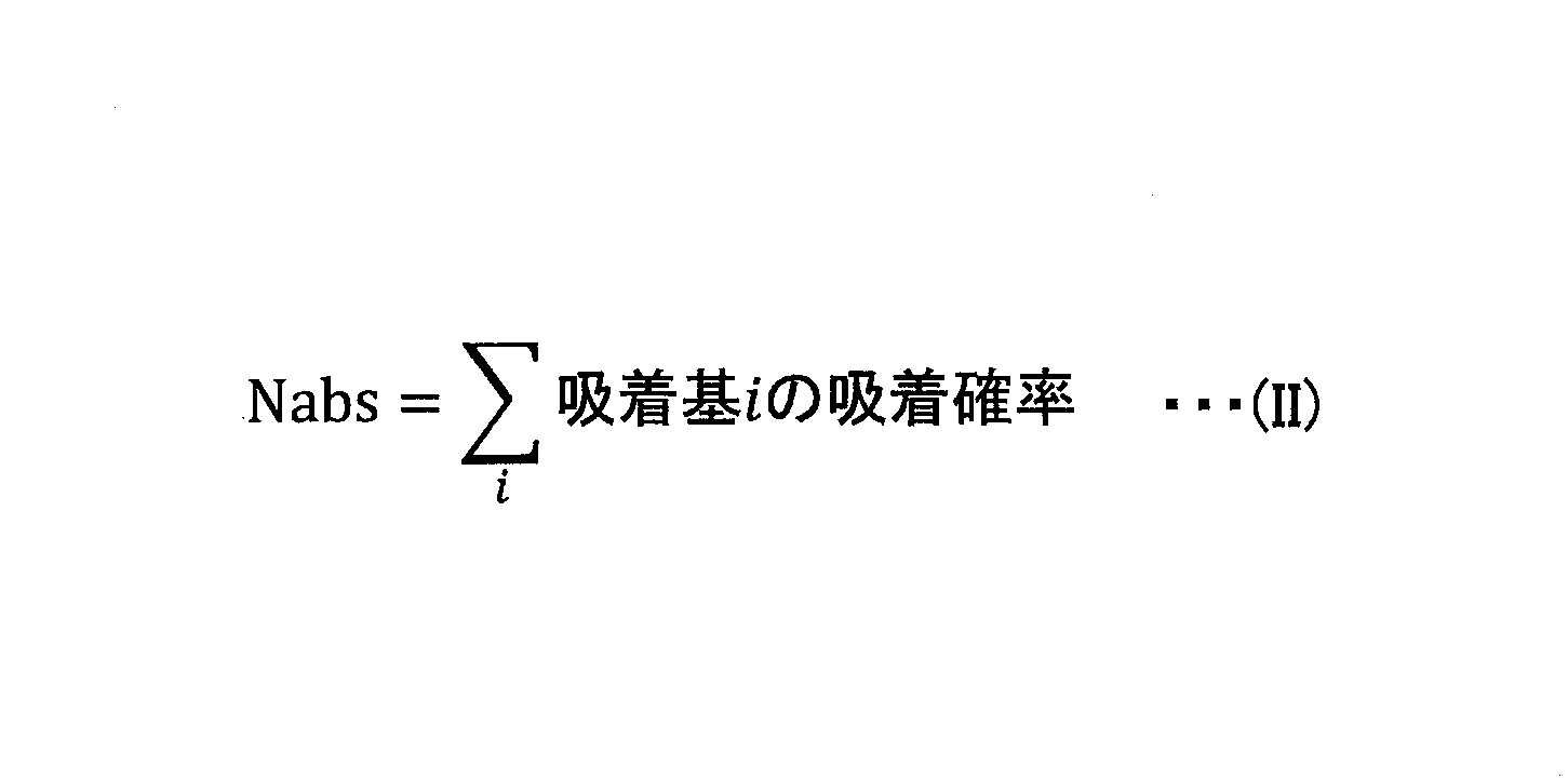
- index Nabs of the degree of adsorption of the lubricating layer. That is, the index Nabs is expressed by the following equation (II).
- the step of constructing the lubricant molecular model and the protective layer model, the step of constructing the initial model of the lubricant layer, and the step of constructing using the molecular dynamics calculation are carried out in the same manner as the steps included in the above-mentioned step of evaluating the lubricant according to the present embodiment. do.
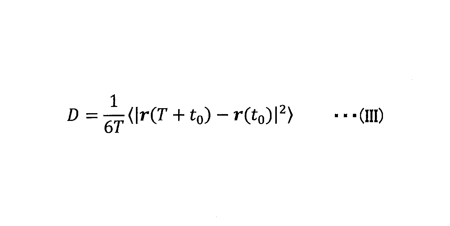
- the self-diffusivity coefficient D of the target lubricant molecule is calculated by the following equation (III).
- t 0 is the initial time
- r (t) is the position of the center of gravity of the molecule at time t.
- the self-diffusion coefficient calculated from the lubrication layer simulation is used as an index of the degree of lubrication of the lubrication layer.
- the molecule whose lubricity value is measured in the experiment relatively evaluates the lubricity of the lubricating layer based on the calculated index of the degree of lubricity.
- the lubrication layer performance evaluation method can also evaluate the performance of the lubrication layer based on the above-mentioned two indexes of the adsorption degree index and the lubrication degree index.
- the performance of the lubricating layer can be relatively evaluated based on the index of the degree of adsorption and the degree of lubrication calculated for the molecule whose experimental result is clear.
- a in the general formula (4) represents an integer of 1 to 3
- b represents an integer of 0 to 10.
- C in the general formula (5) represents an integer of 1 to 3
- d represents an integer of 0 to 10.
- e represents an integer of 1 to 3.
- f represents an integer of 1 to 3.
- g represents 1 to 3. Represents an integer.
- FIG. 1 is a schematic diagram for explaining the structure of the protective layer used in the simulation.
- the dark circle 30 indicates a nitrogen atom
- the light circle 31 indicates a carbon atom
- the unit structure of each nitrogen-doped graphene is set as a periodic boundary condition setting in which the unit structure is repeated infinitely in the plane direction.
- the arrows in FIG. 1 indicate the plane direction in which the unit structure is repeated.
- Each nitrogen-doped graphene is obtained by substituting a part of the carbon atom of graphene with a nitrogen atom.
- the ratio of nitrogen atoms in each nitrogen-doped graphene was set to 12.5% (number basis).
- B3LYP / 6-31G * is used as a combination of parameters / basis functions of the density functional theory to calculate the stable structure of the lubricant molecule, and the atomic charge in the obtained stable structure is calculated by the Mulliken population analysis. bottom.
- HSEH1PBE / 6-31G * was used as a combination of the parameters / basis functions of the density functional theory, and the atomic charge in the obtained stable structure was calculated by Mulliken population analysis.
- a Gaussian® 16 program package from Gaussian was used for these quantum chemistry calculations.
- lubrication layer simulation the preparatory calculation for constructing the initial model of the lubricating layer. It consists of two steps of this calculation (hereinafter referred to as lubrication layer simulation) that traces the movement of the actual lubrication layer from the initial layer model.
- the conditions for the lubricant application simulation were set as follows.
- a GAFF force field was used as the molecular force field, and the value of the depth parameter of the Lennard-Jones potential between the protective layer and the lubricating layer was scaled 1/2 times to match the result of the quantum chemistry calculation ( ⁇ ). The parameter was halved from the original).
- the cutoff method was used for the Lennard-Jones interaction. The cutoff distance was 12 ⁇ , where the interaction was negligible.
- a temperature control method a velocity scaling method was used to perform a simulation using an NVT ensemble in which the number of particles (N), the volume (V), and the temperature (T) were constant.
- the molecular dynamics calculation used the COGNAC engine of OCTA, which is free software.
- FIGS. 2A to 2D are schematic views for explaining a lubricant application simulation.
- reference numeral 1a indicates a lubricant molecule
- reference numeral 1b indicates a lubricating layer
- reference numeral 20 indicates a protective layer.
- the unit structure of the protective layer stabilized by quantum chemistry calculation was spread and arranged in a periodic boundary cell of 96 ⁇ ⁇ 84 ⁇ ⁇ 150 ⁇ to form a protective layer 20.
- the protective layer was assumed that the atomic position did not change during the simulation, and the atomic position was fixed.
- lubricant molecules 1a were randomly placed above the surface of the protective layer 20.
- a lubricating layer with a thin film thickness of about 9 ⁇ was created and the physical property values were measured.
- the number of molecules of the lubricant molecule 1a was adjusted so that the film thickness in the thermal equilibrium state at room temperature was about 9 ⁇ when the lubricating layer 1b was formed.
- FIGS. 2 (c) and 2 (d) a downward force is applied to the hydrogen atom arranged at the end of the lubricant molecule 1a, and the molecular dynamics calculation is executed under normal temperature conditions of 300 K. By doing so, the lubricant molecule 1a was lowered, and the lubricant layer 1b was formed on the surface of the protective layer 20, which was used as an initial model of the lubricant layer.
- FIG. 2C is a structure in the middle of calculation
- FIG. 2D is a structure of the lubrication layer 1b after calculation at 30 ps.
- the GAFF force field is used as the molecular force field, and the value of the depth parameter of the Lennard-Jones potential between the protective layer and the lubricating layer is halved to match the result of the quantum chemical calculation. Scaled (the parameter of ⁇ was halved).
- the cutoff method was used for the Lennard-Jones interaction. The cutoff distance was 12 ⁇ , where the interaction was negligible.
- the Particle-Particle Particle-Mesh Ewald method was used to calculate the long-distance Coulomb interaction.
- a velocity scaling method was used to perform a simulation using an NVT ensemble in which the number of particles (N), the volume (V), and the temperature (T) were constant.
- the molecular dynamics calculation used LAMMPS, which is free software.
- the distance between the protective layer in the "sufficiently close state" and the adsorbent group was set to 2 ⁇ or less for the hydroxyl group and 3 ⁇ or less for the amino group and the nitrile group.
- the self-diffusion coefficient of the lubricant molecule was calculated and used as an index of the degree of lubrication.
- the displacement of the lubricant molecule in the simulation for 6 ns at 300 K was used to calculate the self-diffusion coefficient.
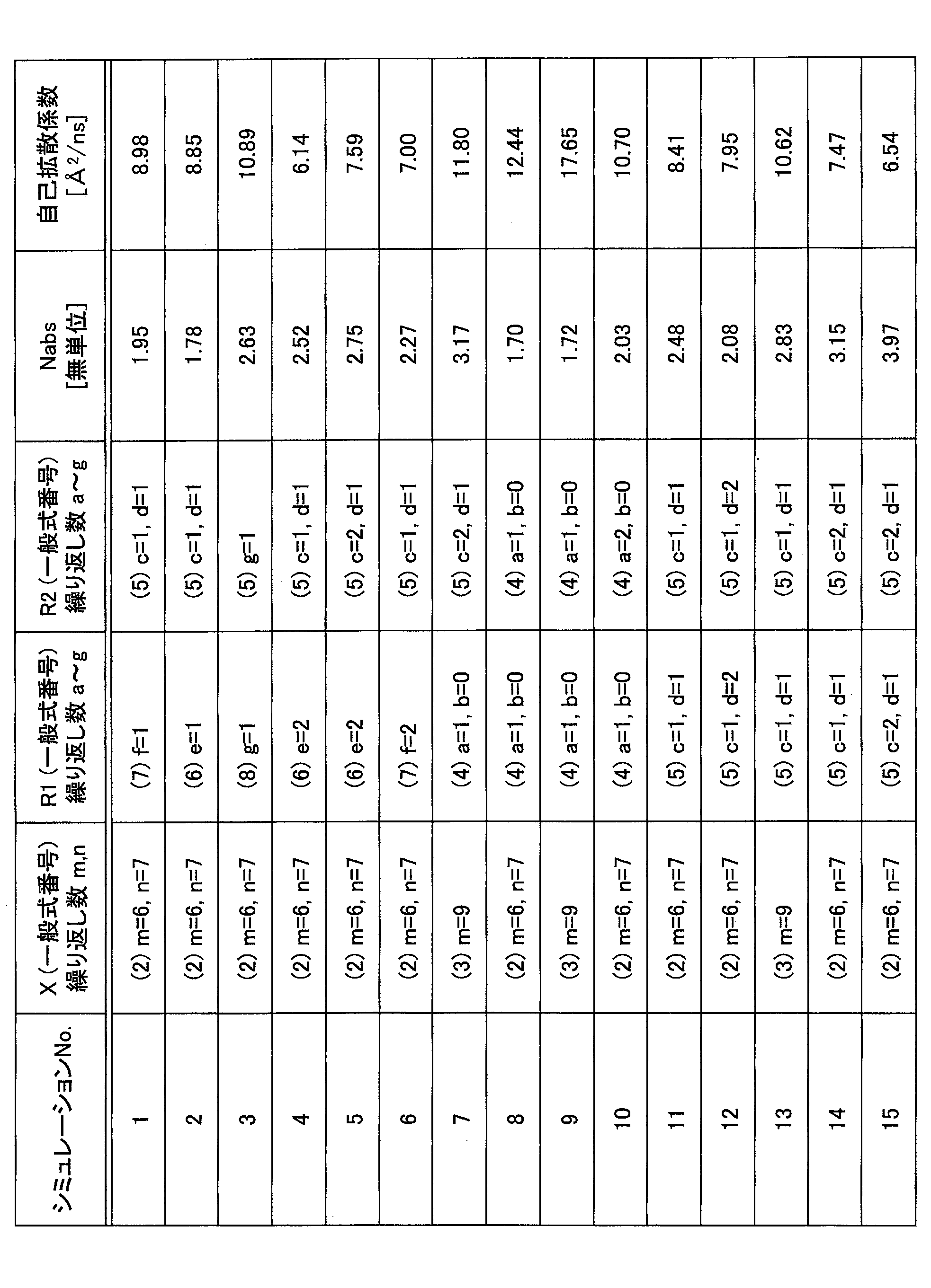
- Table 1 shows the calculated structure of the lubricating layer and the calculation results of the index of the degree of adsorption (Nabs) and the index of the degree of lubrication (self-diffusion coefficient).
- the simulation No. Reference numeral 4 is a lubricant molecule that serves as a reference for adsorptivity.
- a lubricant molecule of Nabs larger than 4 is a lubricant molecule capable of forming a lubricating layer having more excellent adsorptivity.
- Simulation No. Reference numeral 3 is a lubricant molecule that serves as a reference for lubricity.
- a lubricant molecule having a self-diffusion coefficient larger than 3 is a lubricant molecule capable of forming a lubricating layer having better lubricity.
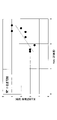
- FIG. 1 a scatter diagram showing both Nabs and the self-diffusion coefficient is shown in FIG.
- the vertical axis is Nabs, and the reference No.
- the result of 4 is shown by a horizontal broken line.
- the horizontal axis is the self-diffusion coefficient, and the reference No.
- the result of 3 is shown by a vertical broken line.
- FIG. 4 shows the relationship between the evaluation value of the levitation test and the Nabs calculated by the simulation.
- the coefficient of determination R2 was about 0.6728, so that there was a sufficient correlation between the buoyancy and Nabs, and the superiority or inferiority of the levitation was judged using Nabs. I was able to confirm that I could do it.
- FIG. 5 shows the relationship between the evaluation value of the lubricity test and the self-diffusion coefficient calculated by the simulation.
- the coefficient of determination R2 was about 0.8071, so there was a sufficient correlation between the lubricity and the self-diffusion coefficient, and the lubricity was obtained using the self-diffusion coefficient. It was confirmed that the superiority or inferiority of can be judged.
- the method for evaluating the performance of the lubricating layer can be suitably used as a method for evaluating the performance of the lubricating layer used for a magnetic recording medium or the like.
Landscapes
- Engineering & Computer Science (AREA)
- Computing Systems (AREA)
- Theoretical Computer Science (AREA)
- Physics & Mathematics (AREA)
- Life Sciences & Earth Sciences (AREA)
- Health & Medical Sciences (AREA)
- General Health & Medical Sciences (AREA)
- Bioinformatics & Cheminformatics (AREA)
- Spectroscopy & Molecular Physics (AREA)
- Bioinformatics & Computational Biology (AREA)
- General Physics & Mathematics (AREA)
- Chemical & Material Sciences (AREA)
- Analytical Chemistry (AREA)
- Biochemistry (AREA)
- Immunology (AREA)
- Pathology (AREA)
- Magnetic Record Carriers (AREA)
- Lubricants (AREA)
Abstract
Description
前記潤滑剤分子モデルと前記保護層モデルから構築した潤滑層初期モデルの分子動力学計算を実施する工程と、
前記分子動力学計算の結果から潤滑剤分子の保護層への吸着度合いの指標を算出する工程と、
を含む潤滑層の性能評価方法。
[2] 潤滑剤分子モデルと保護層モデルとを、量子化学計算を用いて準備する工程と、
前記潤滑剤分子モデルと前記保護層モデルから構築した潤滑層初期モデルの分子動力学計算を実施する工程と、
前記分子動力学計算の結果から潤滑剤分子の保護層上での潤滑度合いの指標を算出する工程と、
を含む潤滑層の性能評価方法。
[3] [1]で算出された前記吸着度合いの指標と、[2]で算出された前記潤滑度合いの指標との2つの指標に基づいて、潤滑層の性能を評価する潤滑層の性能評価方法。
[4] 前記保護層が、磁気記録媒体表面に形成された保護層であり、
前記潤滑剤分子が、磁気記録媒体用の潤滑剤分子である、[1]~[3]の何れか一つの潤滑層の性能評価方法。
本実施形態に係る評価方法は、最初に潤滑層を構成する潤滑剤分子及び保護層のモデルを構築する。
磁気記録媒体に使用される潤滑剤分子としては、例えば、パーフルオロエーテル鎖(-CF2-)を含む繰り返し構造を有するフッ素系のポリマーの末端に、ヒドロキシ基等の極性基を有する化合物が挙げられる。その分子量としては、1000~10000程度のものが挙げられる。

保護層は、記録層を保護するための層であり、炭素原子又は炭化ケイ素から構成される。炭素原子からなる層の単位構造としては、グラフェンやダイヤモンドカーボンの単位構造が使用できる。このグラフェンやダイヤモンドカーボン構造では、酸素や窒素等をドープされていることが好ましい。これらを吸着サイトとすることで、潤滑剤の極性基との結合を強くすることが可能であるためである。
潤滑層初期モデル構築工程では、前工程で作成した潤滑剤分子モデルと保護層モデルとを用いて、潤滑層の初期モデル(潤滑層初期モデル)を構築する。
分子動力学計算を実施する工程では、潤滑層初期モデル構築工程で構築した潤滑層初期モデルを用いて、分子動力学計算を実施する。
・セルのサイズ:96Å×84Å×150Å(周期境界セル)
・追跡時間:6ns(1ステップの時間1ps、総ステップ数600万ステップ)
・温度:300K(室温を仮定)
・分子力場:GAFF力場
・クーロン相互作用の計算手法:Particle-Particle Particle-Mesh Ewald法
潤滑剤分子は、分子内の極性基と保護層モデルの吸着サイトとの相互作用により吸着する。そこで、潤滑剤分子内のある1つの吸着基について、保護層モデルの表面に十分近づいている状態を、「保護層に吸着している状態」と定義する。
吸着基Aの吸着割合=吸着している状態にある吸着基Aの数/潤滑剤分子の総数 ・・・(I)
潤滑剤分子の潤滑性は、分子動力学計算の結果得られた、潤滑剤分子の自己拡散係数を算出し、それを潤滑層の潤滑度合いの指標として使用する。
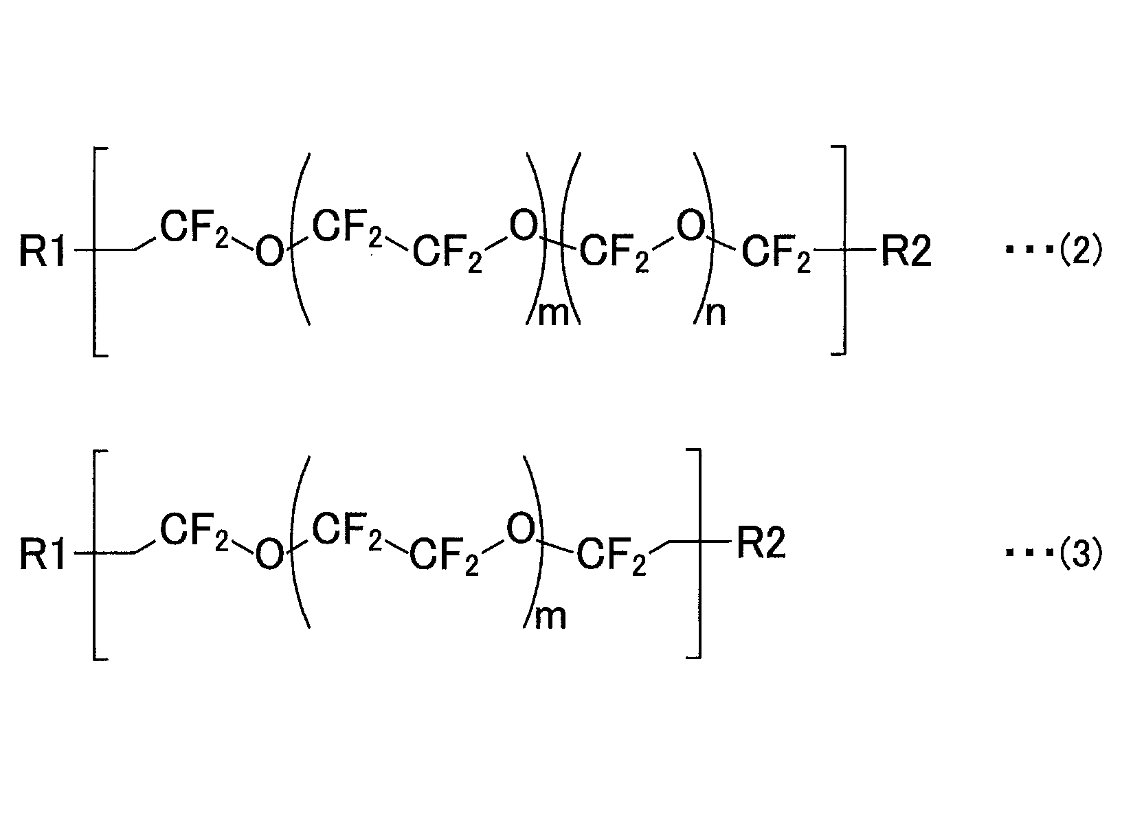
前述した一般式(1)中の主鎖部分Xとして、下記一般式(2)又は下記一般式(3)のものを用いた。

(保護層)
図1は、シミュレーションに使用した保護層の構造を説明するための模式図である。図1に示すように、シミュレーションでは、保護層として2層の窒素ドープグラフェンを使用した。ここで、濃色の丸30は窒素原子を示し、淡色の丸31は炭素原子を示し、各窒素ドープグラフェンの単位構造が平面方向に無限に繰り返される周期境界条件設定とした。図1中の矢印は、単位構造が繰り返される平面方向を示す。各窒素ドープグラフェンは、グラフェンの炭素原子の一部を窒素原子により置換したものである。各窒素ドープグラフェン中の窒素原子の割合は12.5%(数基準)に設定した。
前述した、潤滑剤分子と、保護層の単位構造について、量子化学計算により、安定構造及び各原子の電荷を求めた。それぞれ安定構造を計算する構造の最適化を実行した後、その構造における原子電荷を算出した。
分子動力学計算を実施する工程は、保護層モデルの上に潤滑剤分子モデルを配置し、潤滑層初期モデルを構築する準備計算(以下、潤滑剤塗布シミュレーション、と記す。)と、構築した潤滑層初期モデルから実際の潤滑層の動きを追跡する本計算(以下、潤滑層シミュレーション、と記す。)の二工程からなる。
上記のようにして作成した構造と各原子の電荷の情報を含む潤滑剤分子モデル及び保護層モデルを使用し、潤滑層シミュレーションの初期構造となる潤滑層初期モデルを構築した。室温(300K)において潤滑層が保護層を被覆した状態を再現するため、本実施例では、潤滑剤塗布シミュレーションを実施した。
潤滑剤シミュレーションでは、分子力場としてGAFF力場を使用し、量子化学計算の結果と合致するように保護層と潤滑層の間のLennard-Jonesポテンシャルの深さパラメータの値を1/2倍にスケールした(εのパラメータを元の1/2倍にした)。また、Lennard-Jones相互作用には、カットオフ法を用いた。カットオフ距離は、相互作用が無視できると見なせる12Åとした。長距離クーロン相互作用の計算には、Particle-Particle Particle-Mesh Ewald法を使用した。温度制御法として、速度スケーリング法を用いて、粒子数(N)と体積(V)と温度(T)を一定にしたNVTアンサンブルによるシミュレーションを行った。分子動力学計算は、フリーソフトウェアであるLAMMPSを使用した。
潤滑層の吸着度合いの指標と潤滑度合いの指標を算出した。
前述した方法により、潤滑層の吸着度合いの指標Nabsを算出した。
実施形態に示す通り、潤滑剤分子の自己拡散係数を算出し、潤滑度合いの指標とした。自己拡散係数の算出には、300Kでの6ns間のシミュレーションにおける潤滑剤分子の変位を利用した。

31 炭素原子
1a 潤滑剤分子
1b 潤滑層
20 保護層
Claims (4)
- 潤滑剤分子モデルと保護層モデルとを、量子化学計算を用いて準備する工程と、
前記潤滑剤分子モデルと前記保護層モデルから構築した潤滑層初期モデルの分子動力学計算を実施する工程と、
前記分子動力学計算の結果から潤滑剤分子の保護層への吸着度合いの指標を算出する工程と、
を含む潤滑層の性能評価方法。 - 潤滑剤分子モデルと保護層モデルとを、量子化学計算を用いて準備する工程と、
前記潤滑剤分子モデルと前記保護層モデルから構築した潤滑層初期モデルの分子動力学計算を実施する工程と、
前記分子動力学計算の結果から潤滑剤分子の保護層上での潤滑度合いの指標を算出する工程と、
を含む潤滑層の性能評価方法。 - 請求項1で算出された前記吸着度合いの指標と、請求項2で算出された前記潤滑度合いの指標との2つの指標に基づいて、潤滑層の性能を評価する潤滑層の性能評価方法。
- 前記保護層が、磁気記録媒体表面に形成された保護層であり、
前記潤滑剤分子が、磁気記録媒体用の潤滑剤分子である、請求項1~3の何れか一項に記載の潤滑層の性能評価方法。
Priority Applications (3)
| Application Number | Priority Date | Filing Date | Title |
|---|---|---|---|
| CN202180070592.2A CN116490761A (zh) | 2020-10-16 | 2021-10-13 | 润滑层的性能评价方法 |
| JP2022557033A JP7790350B2 (ja) | 2020-10-16 | 2021-10-13 | 潤滑層の性能評価方法 |
| US18/248,591 US20230386613A1 (en) | 2020-10-16 | 2021-10-13 | Method for evaluating performance of lubricating layer |
Applications Claiming Priority (2)
| Application Number | Priority Date | Filing Date | Title |
|---|---|---|---|
| JP2020-174602 | 2020-10-16 | ||
| JP2020174602 | 2020-10-16 |
Publications (1)
| Publication Number | Publication Date |
|---|---|
| WO2022080402A1 true WO2022080402A1 (ja) | 2022-04-21 |
Family
ID=81208264
Family Applications (1)
| Application Number | Title | Priority Date | Filing Date |
|---|---|---|---|
| PCT/JP2021/037849 Ceased WO2022080402A1 (ja) | 2020-10-16 | 2021-10-13 | 潤滑層の性能評価方法 |
Country Status (4)
| Country | Link |
|---|---|
| US (1) | US20230386613A1 (ja) |
| JP (1) | JP7790350B2 (ja) |
| CN (1) | CN116490761A (ja) |
| WO (1) | WO2022080402A1 (ja) |
Citations (3)
| Publication number | Priority date | Publication date | Assignee | Title |
|---|---|---|---|---|
| JP2010168512A (ja) * | 2009-01-26 | 2010-08-05 | Hitachi Ltd | 潤滑剤、および、それを用いた磁気ディスク装置 |
| WO2013054393A1 (ja) * | 2011-10-11 | 2013-04-18 | 株式会社日立製作所 | 潤滑剤、及びそれを用いた磁気ディスク装置 |
| US20140368947A1 (en) * | 2013-06-14 | 2014-12-18 | HGST Netherlands B.V. | Magnetic recording medium lubricant mixture and systems thereof |
Family Cites Families (6)
| Publication number | Priority date | Publication date | Assignee | Title |
|---|---|---|---|---|
| JP2003162810A (ja) * | 2001-11-28 | 2003-06-06 | Hitachi Ltd | 磁気記録媒体 |
| JP5293847B2 (ja) * | 2012-01-27 | 2013-09-18 | 富士電機株式会社 | 磁気記録媒体 |
| JP6040074B2 (ja) * | 2013-03-27 | 2016-12-07 | 昭和電工株式会社 | 磁気記録媒体の製造方法 |
| US9384771B2 (en) * | 2013-12-20 | 2016-07-05 | HGST Netherlands B.V. | Lubricants providing magnetic head wear reduction and magnetic spacing improvement |
| CN103745046B (zh) * | 2013-12-26 | 2016-07-13 | 武汉轻工大学 | 一种根据分子动力学模拟预测润滑基础油减摩性能的方法 |
| JP7126488B2 (ja) * | 2017-03-02 | 2022-08-26 | 昭和電工株式会社 | 磁気記録媒体、含フッ素エーテル化合物および磁気記録媒体用潤滑剤 |
-
2021
- 2021-10-13 CN CN202180070592.2A patent/CN116490761A/zh active Pending
- 2021-10-13 JP JP2022557033A patent/JP7790350B2/ja active Active
- 2021-10-13 WO PCT/JP2021/037849 patent/WO2022080402A1/ja not_active Ceased
- 2021-10-13 US US18/248,591 patent/US20230386613A1/en active Pending
Patent Citations (3)
| Publication number | Priority date | Publication date | Assignee | Title |
|---|---|---|---|---|
| JP2010168512A (ja) * | 2009-01-26 | 2010-08-05 | Hitachi Ltd | 潤滑剤、および、それを用いた磁気ディスク装置 |
| WO2013054393A1 (ja) * | 2011-10-11 | 2013-04-18 | 株式会社日立製作所 | 潤滑剤、及びそれを用いた磁気ディスク装置 |
| US20140368947A1 (en) * | 2013-06-14 | 2014-12-18 | HGST Netherlands B.V. | Magnetic recording medium lubricant mixture and systems thereof |
Non-Patent Citations (1)
| Title |
|---|
| MYUNG S. JHON, SATORU IZUMISAWA, QIAN GUO, DAVID M. PHILLIPS, YIAO-TEE HSIA: "Simulation of Nanostructured Lubricant Films", IEEE TRANSACTIONS ON MAGNETICS, vol. 39, no. 2, 1 March 2003 (2003-03-01), USA, pages 754 - 758, XP011075907, ISSN: 0018-9464 * |
Also Published As
| Publication number | Publication date |
|---|---|
| CN116490761A (zh) | 2023-07-25 |
| JPWO2022080402A1 (ja) | 2022-04-21 |
| JP7790350B2 (ja) | 2025-12-23 |
| US20230386613A1 (en) | 2023-11-30 |
Similar Documents
| Publication | Publication Date | Title |
|---|---|---|
| CN110366575B (zh) | 磁记录介质、含氟醚化合物及磁记录介质用润滑剂 | |
| Oliver et al. | Molecular simulations of hydrogen diffusion in underground porous media: Implications for storage under varying pressure, confinement, and surface chemistry conditions | |
| Ge et al. | Femtosecond studies of electron dynamics at interfaces | |
| Sui et al. | Competitive sorption of CO2/CH4 and CO2 capture on modified silica surfaces: A molecular simulation | |
| Klatte et al. | Molecular dynamics simulations of tethered alkane chromatographic stationary phases | |
| Ethier et al. | Modeling individual and pairs of adsorbed polymer-grafted nanoparticles: structure and entanglements | |
| Chakrabarty et al. | Insights on finite size effects in ab initio study of CO adsorption and dissociation on Fe 110 surface | |
| Yokoyama et al. | Surface structure of asymmetric fluorinated block copolymers | |
| JP7790350B2 (ja) | 潤滑層の性能評価方法 | |
| Yang et al. | Molecular dynamics study on enhancement of mechanical and tribological properties of polytetrafluoroethylene composites by incorporating hexagonal boron nitride nanosheets | |
| Yu et al. | Sn-Cd modified Ti2CO2 MXene for enhanced harmful gas adsorption: A DFT study | |
| Irving et al. | Diffusion on a self-assembled monolayer: molecular modeling of a bound+ mobile lubricant | |
| Ma et al. | Molecular Dynamics Simulation of Nanoparticle‐Driven Oil Detachment in Nanochannels | |
| Patrykiejew et al. | Density functional approach to adsorption of simple fluids on surfaces modified with a brush-like chain structure | |
| Li et al. | Ab Initio Molecular Dynamics Study of H2 Dissociation Mechanisms on Cu13 and Defective Graphene‐supported Cu13 Clusters: Active Sites, Energy Barriers and Adsorption States | |
| Chiarcos et al. | Thermodynamic vs Kinetic Control of Brush Composition in Grafting to Reactions of Disperse Polymer Systems in Melt | |
| Konstantakou et al. | Determination of pore size distribution in microporous carbons based on CO2 and H2 sorption data | |
| Pötting et al. | Self‐Diffusion on Au (100): A Density Functional Theory Study | |
| Milchev | Conformational and dynamic properties of polymer chains adsorbed on hard surfaces | |
| Torki et al. | Use of Fe3O4 nanoparticles for adsorption of asphaltene from heavy and ultra-heavy materials: A molecular dynamics study | |
| Ibrahim et al. | Bridging Nanostructure Growth and Gas-Sensing Kinetics in Metal-Functionalized Graphene Using Machine-Learned Molecular Dynamics | |
| 境界潤滑における高分子添加剤 et al. | Molecular Dynamics Study of Conformational and Mechanochemical Behavior of Polymeric Additives and Lubricants in Boundary Lubrication | |
| Hur | Modified potential for atomistic simulation of the growth of carbon materials from binary alloy catalysts | |
| Klatte | Molecular dynamics simulations of liquid chromatographic interphases | |
| Donev | Carbon nanotube transistors: Capacitance measurements, localized damage, and use as gold scaffolding |
Legal Events
| Date | Code | Title | Description |
|---|---|---|---|
| 121 | Ep: the epo has been informed by wipo that ep was designated in this application |
Ref document number: 21880140 Country of ref document: EP Kind code of ref document: A1 |
|
| ENP | Entry into the national phase |
Ref document number: 2022557033 Country of ref document: JP Kind code of ref document: A |
|
| WWE | Wipo information: entry into national phase |
Ref document number: 202180070592.2 Country of ref document: CN |
|
| NENP | Non-entry into the national phase |
Ref country code: DE |
|
| 122 | Ep: pct application non-entry in european phase |
Ref document number: 21880140 Country of ref document: EP Kind code of ref document: A1 |