WO2022080017A1 - Nœud de réseau central pour la gestion de session, nœud de réseau central pour la gestion de mobilité, et procédé impliquant ceux-ci - Google Patents
Nœud de réseau central pour la gestion de session, nœud de réseau central pour la gestion de mobilité, et procédé impliquant ceux-ci Download PDFInfo
- Publication number
- WO2022080017A1 WO2022080017A1 PCT/JP2021/031366 JP2021031366W WO2022080017A1 WO 2022080017 A1 WO2022080017 A1 WO 2022080017A1 JP 2021031366 W JP2021031366 W JP 2021031366W WO 2022080017 A1 WO2022080017 A1 WO 2022080017A1
- Authority
- WO
- WIPO (PCT)
- Prior art keywords
- restrictions
- core network
- network node
- network
- pdu session
- Prior art date
Links
- 238000000034 method Methods 0.000 title claims description 64
- 230000004044 response Effects 0.000 claims abstract description 27
- 230000015654 memory Effects 0.000 claims description 69
- 238000005516 engineering process Methods 0.000 claims description 31
- 238000012986 modification Methods 0.000 claims description 28
- 230000004048 modification Effects 0.000 claims description 28
- 230000006870 function Effects 0.000 claims description 26
- 230000009849 deactivation Effects 0.000 claims description 4
- 238000007726 management method Methods 0.000 description 111
- 101100477785 Saccharomyces cerevisiae (strain ATCC 204508 / S288c) SMF3 gene Proteins 0.000 description 54
- 238000012545 processing Methods 0.000 description 24
- 238000004891 communication Methods 0.000 description 17
- 238000010586 diagram Methods 0.000 description 9
- 230000011664 signaling Effects 0.000 description 9
- 210000000623 ulna Anatomy 0.000 description 8
- 229910008956 UPF6 Inorganic materials 0.000 description 5
- 230000005540 biological transmission Effects 0.000 description 4
- 238000013523 data management Methods 0.000 description 4
- 238000013475 authorization Methods 0.000 description 3
- 238000013507 mapping Methods 0.000 description 3
- 101100348958 Caenorhabditis elegans smf-3 gene Proteins 0.000 description 2
- 241000209094 Oryza Species 0.000 description 2
- 235000007164 Oryza sativa Nutrition 0.000 description 2
- 230000001413 cellular effect Effects 0.000 description 2
- 238000006243 chemical reaction Methods 0.000 description 2
- 238000004590 computer program Methods 0.000 description 2
- 230000006855 networking Effects 0.000 description 2
- 235000009566 rice Nutrition 0.000 description 2
- 230000003068 static effect Effects 0.000 description 2
- 101150119040 Nsmf gene Proteins 0.000 description 1
- 230000003321 amplification Effects 0.000 description 1
- 230000006399 behavior Effects 0.000 description 1
- 230000010267 cellular communication Effects 0.000 description 1
- 239000000919 ceramic Substances 0.000 description 1
- 238000013144 data compression Methods 0.000 description 1
- 238000000354 decomposition reaction Methods 0.000 description 1
- 238000013461 design Methods 0.000 description 1
- 230000000694 effects Effects 0.000 description 1
- 230000002708 enhancing effect Effects 0.000 description 1
- 230000010354 integration Effects 0.000 description 1
- 238000010295 mobile communication Methods 0.000 description 1
- 238000003199 nucleic acid amplification method Methods 0.000 description 1
- 230000003287 optical effect Effects 0.000 description 1
- 239000013307 optical fiber Substances 0.000 description 1
- 230000000737 periodic effect Effects 0.000 description 1
- 230000011218 segmentation Effects 0.000 description 1
- 239000004065 semiconductor Substances 0.000 description 1
- 238000012546 transfer Methods 0.000 description 1
- 230000001052 transient effect Effects 0.000 description 1
- 230000001960 triggered effect Effects 0.000 description 1
Images


Classifications
-
- H—ELECTRICITY
- H04—ELECTRIC COMMUNICATION TECHNIQUE
- H04W—WIRELESS COMMUNICATION NETWORKS
- H04W48/00—Access restriction; Network selection; Access point selection
- H04W48/02—Access restriction performed under specific conditions
- H04W48/04—Access restriction performed under specific conditions based on user or terminal location or mobility data, e.g. moving direction, speed
-
- H—ELECTRICITY
- H04—ELECTRIC COMMUNICATION TECHNIQUE
- H04W—WIRELESS COMMUNICATION NETWORKS
- H04W24/00—Supervisory, monitoring or testing arrangements
- H04W24/02—Arrangements for optimising operational condition
-
- H—ELECTRICITY
- H04—ELECTRIC COMMUNICATION TECHNIQUE
- H04L—TRANSMISSION OF DIGITAL INFORMATION, e.g. TELEGRAPHIC COMMUNICATION
- H04L41/00—Arrangements for maintenance, administration or management of data switching networks, e.g. of packet switching networks
- H04L41/40—Arrangements for maintenance, administration or management of data switching networks, e.g. of packet switching networks using virtualisation of network functions or resources, e.g. SDN or NFV entities
-
- H—ELECTRICITY
- H04—ELECTRIC COMMUNICATION TECHNIQUE
- H04W—WIRELESS COMMUNICATION NETWORKS
- H04W76/00—Connection management
- H04W76/20—Manipulation of established connections
- H04W76/22—Manipulation of transport tunnels
-
- H—ELECTRICITY
- H04—ELECTRIC COMMUNICATION TECHNIQUE
- H04W—WIRELESS COMMUNICATION NETWORKS
- H04W76/00—Connection management
- H04W76/30—Connection release
- H04W76/32—Release of transport tunnels
-
- H—ELECTRICITY
- H04—ELECTRIC COMMUNICATION TECHNIQUE
- H04W—WIRELESS COMMUNICATION NETWORKS
- H04W76/00—Connection management
- H04W76/30—Connection release
- H04W76/34—Selective release of ongoing connections
-
- H—ELECTRICITY
- H04—ELECTRIC COMMUNICATION TECHNIQUE
- H04W—WIRELESS COMMUNICATION NETWORKS
- H04W88/00—Devices specially adapted for wireless communication networks, e.g. terminals, base stations or access point devices
- H04W88/14—Backbone network devices
Definitions
- This disclosure relates to wireless communication networks, especially network slicing.
- Network slicing makes it possible to create multiple logical networks or unvirtualized logical networks on top of physical networks.
- Network slicing may use Network Function Virtualization (NFV) technology and software-defined networking (SDN) technology to create multiple virtualized logical networks on top of a physical network. ..
- NFV Network Function Virtualization
- SDN software-defined networking
- Each logical network is called a network slice.
- Network slices provide specific network capabilities and network characteristics.
- a network slice instance (NSI) is a network function (NF) instance and resources (e.g., computer processing resources, storage, and storage) to form a single network slice.
- Networking resources and one or both of the access network (AN) (Next Generation Radio Access Network (NG-RAN) and Non-3GPP InterWorking Function (N3IWF)).
- AN Next Generation Radio Access Network
- N3IWF Non-3GPP InterWorking Function
- S-NSSAI Single Network Slice Selection Assistance Information
- SST Slice / Service type
- SD Slice Differentiator
- SST means referreds to expected network slice behavior with respect to features and services.
- SD is optional information and complements SST to distinguish between multiple network slices of the same Slice / Service type.
- S-NSSAI can have standard values or non-standard values.
- Standard SST values 1, 2, 3, and 4 are enhanced Mobile Broad Band (eMBB), Ultra Reliable and Low Latency Communication (URLLC), Massive Internet of Things (MIoT), and Vehicle to Everything (V2X). It is associated with slice types.
- the non-standard value of S-NSSAI identifies one network slice within a particular Public Land Mobile Network (PLMN). That is, non-standard SST values are PLMN-specific values and are associated with the PLMN ID of the PLMN to which they are assigned.
- PLMN Public Land Mobile Network
- Each S-NSSAI guarantees network independence in choosing a particular NSI.
- the same NSI may be selected via different S-NSSAIs.
- the same S-NSSAI may be associated with different NSIs.
- Each network slice may be uniquely identified by S-NSSAI.
- S-NSSAI There are two types of S-NSSAI, which are known as S-NSSAI and Mapped S-NSSAI.
- S-NSSAI identifies the network slice provided by the serving Public Land Mobile Network (PLMN) to which the UE connects. Therefore, when the home network is in the area, S-NSSAI identifies the network slice of the home network (e.g., Home PLMN (HPLMN)).
- PLMN Public Land Mobile Network
- S-NSSAI identifies the network slice of the roaming network (e.g., Visited PLMN (VPLMN)).
- PLMN Public Land Mobile Network
- VPN Visited PLMN
- Mapped S-NSSAI is a Home PLMN (HPLMN) S-NSSAI that is mapped (associated or applicable) to the S-NSSAI that identifies the network slice of the roaming network when the UE is roaming. It may be S-NSSAI included in the subscriber information of the UE user.
- HPLMN Home PLMN
- S-NSSAI included in the subscriber information of the UE user.
- NSSAI Network Slice Selection Assistance Information
- Configured NSSAI Requested NSSAI
- Allowed NSSAI Rejected NSSAI
- Pending NSSAI Pending NSSAI
- Configured NSSAI includes at least one S-NSSAI, each applicable to at least one PLMN.
- the Configured NSSAI is set by, for example, the Serving PLMN and is applied to the Serving PLMN.
- the Configured NSSAI may be the Default Configured NSSAI.
- the Default Configured NSSAI is set by the Home PLMN (HPLMN) and applies to any (any) PLMNs for which no specific (specific) Configured NSSAI is provided.
- Default Configured NSSAI is provisioned from Unified Data Management (UDM) of HPLMN to a wireless terminal (User Equipment (UE)) via Access and Mobility Management Function (AMF), for example.
- UDM Unified Data Management
- UE User Equipment
- AMF Access and Mobility Management Function
- the Requested NSSAI is signaled to the network by the UE, for example, in a registration procedure, allowing the network to determine a Serving AMF, at least one network slice, and at least one NSI for that UE.
- Allowed NSSAI indicates at least one S-NSSAI provided to the UE by the Serving PLMN and can be used by the UE in the current Registration Area (RA) of the Serving PLMN. Allowed NSSAI is determined by the AMF of the Serving PLMN, for example, during the registration procedure. Allowed NSSAI is signaled to the UE by the network (i.e., AMF) and stored in the respective memories (e.g., non-volatile) of the AMF and the UE.
- the network i.e., AMF
- memories e.g., non-volatile
- Rejected NSSAI includes at least one S-NSSAI rejected by the current (current) PLMN.
- Rejected NSSAI is sometimes called rejected S-NSSAIs.
- S-NSSAI is either rejected by the current PLMN as a whole or rejected by the current (current) registration area (RA). If the AMF rejects any one of at least one S-NSSAI included in the Requested NSSAI, for example, in the registration procedure of the UE, these are included in the Rejected NSSAI.
- the Rejected NSSAI is signaled to the UE by the network (i.e., AMF) and stored in the respective memories of the AMF and the UE.
- Pending NSSAI indicates at least one S-NSSAI for which authentication and authorization (Network Slice-Specific Authentication and Authorization (NSSAA)) specialized for network slices are pending.
- the Serving PLMN must perform NSSAA on the HPLMN's S-NSSAI (s), which is subject to NSSAA based on subscription information.
- AMF implements Extensible Authentication Protocol (EAP) -based authorization procedure (invoke). EAP-based authentication procedure takes a relatively long time to obtain the result (outcome).
- EAP Extensible Authentication Protocol
- AMF determines Allowed NSSAI as described above in the registration procedure of UE, but does not include S-NSSAI (s) imposed by NSSAA in the Allowed NSSAI, and instead includes them in Pending NSSAI. Include in. Pending NSSAI is signaled to the UE by the network (i.e., AMF) and stored in the respective memories of AMF and UE.
- AMF the network
- the 3rd Generation Partnership Project (3GPP) is considering enhancing network slice functions for Release 17.
- 3GPP Technical Specification Group Services and System Aspects (TSG-SA) Working Group 1 (WG1) is for Release 18 to investigate the feasibility of Enhanced Access to Support of Network Slice.
- Approved a new working / study item (see Non-Patent Document 1).
- One of the objectives of this study item is to limit network slices to certain frequency bands / subbands, RadioAccess Technologies (RATs), geographic areas, networks, applications, etc. Identifying various deployments and usage scenarios of network slices, when there is a restriction of network slices to e.g., ceramic frequency bands / subbands, RATs, geographical areas ..
- UE User Equipment
- RATs RadioAccess Technologies
- 3GPP SA WG1 "New WID on Study on Enhanced Access to and Support of Network Slice (from S1-202284)", SP-200571, 3GPP TSG SA Meeting # 88e, Electronic Meeting, June 30th-July 3GPP TS 23.501 V16.6.0 (2020-09) “3rd Generation Partnership Project; Technical Specification Group Services and System Aspects; System architecture for the 5G System (5GS); Stage 2 (Release 16)”, September 2020
- One of the objectives to be achieved by the embodiments disclosed herein is to provide devices, methods, and programs that contribute to the realization of session management adapted to the restrictions on the use of network slices. It should be noted that this object is only one of the purposes that the plurality of embodiments disclosed herein seek to achieve. Other objectives or issues and novel features will be apparent from the description or accompanying drawings herein.
- the core network node for session management includes at least one memory and at least one processor coupled to the at least one memory.
- the at least one processor is configured to receive a report from the core network node for mobility management indicating that a restriction update for the use of network slices by the UE has occurred.
- the at least one processor is further configured to control the release or modification of the established PDU Session of the UE associated with the network slice in response to receiving the report.
- the core network node for mobility management includes at least one memory and at least one processor coupled to the at least one memory.
- the at least one processor is configured to send a report indicating that the limit update has occurred to the core network node for session management in response to the limit update for the use of network slices by the UE.
- the method performed by the core network node for session management includes the following steps: (A) receive a report from the core network node for mobility management indicating that a restriction update for the use of network slices by the UE has occurred, and (b) said at least one processor further receives the report. To control the release or modification of the established PDU Session of the UE associated with the network slice in response to.
- the method performed by the core network node for mobility management is to report for session management that the limit update has occurred in response to the limit update for the use of network slices by the UE. Includes sending to core network nodes.
- the core network node for mobility management includes at least one memory and at least one processor coupled to the at least one memory.
- the at least one processor releases the established PDU Session associated with the network slice or deactivates the user plane resource of the established PDU Session in response to an update of the restriction on the use of the network slice. Configured to request the core network node for session management.
- the method performed by the core network node for mobility management is to release the established PDU Session associated with the network slice or the established PDU in response to an update of the restriction on the use of the network slice. Includes requesting the core network node for session management to deactivate the user plane resource for Session.
- the core network node for mobility management includes at least one memory and at least one processor coupled to the at least one memory.
- the at least one processor is configured to receive a first Non-Access Stratum (NAS) message from the UE, including a Session Management (SM) message requesting the establishment of a PDU Session.
- the at least one processor is configured to determine whether or not usage restrictions are imposed or need to be imposed on the network slice identifier associated with the PDU Session.
- the at least one processor if the network slice identifier is or needs to be subject to the usage restrictions, stops forwarding the SM message to the core network node for session management and the NAS message. Is configured to reject.
- the usage restrictions are restrictions on the radio frequencies that can use network slices, restrictions on wireless access technologies that can use network slices, restrictions on geographical areas that can use network slices, and restrictions on applications that can use network slices. , At least one of them is included.
- the method performed by the core network node for mobility management includes the following steps: (A) Receiving from the UE a first NAS message containing an SM message requesting the establishment of a PDU Session. (B) Determining whether or not usage restrictions are imposed or need to be imposed on the network slice identifier associated with the PDU Session, and (c) said usage restrictions on the network slice identifier. If is imposed or needs to be imposed, stop forwarding the SM message to the core network node for session management and reject the NAS message.
- the usage restrictions are restrictions on the radio frequencies that can use network slices, restrictions on wireless access technologies that can use network slices, restrictions on geographical areas that can use network slices, and restrictions on applications that can use network slices. , At least one of them is included.
- the core network node for mobility management includes at least one memory and at least one processor coupled to the at least one memory.
- the at least one processor is configured to receive a NAS message from the UE, including an SM message requesting the establishment of a PDU Session.
- the at least one processor is configured to determine if the network slice identifier associated with the PDU Session needs to be restricted.
- the SM message with an indication that the establishment of the PDU Session should be rejected because of the usage restriction if the network slice identifier needs to be subject to the usage restriction. Is configured to be forwarded to the core network node for session management.
- the usage restrictions are restrictions on the radio frequencies that can use network slices, restrictions on wireless access technologies that can use network slices, restrictions on geographical areas that can use network slices, and restrictions on applications that can use network slices. , At least one of them is included.
- the core network node for session management includes at least one memory and at least one processor coupled to the at least one memory.
- the at least one processor is configured to receive a control message from a core network node for mobility management, including a first SM message requesting the establishment of a PDU Session for the UE.
- the at least one processor is configured to reject the establishment of the PDU Session if the control message contains an indication that the establishment of the PDU Session should be rejected due to usage restrictions.
- the usage restrictions are restrictions on the radio frequencies that can use network slices, restrictions on wireless access technologies that can use network slices, restrictions on geographical areas that can use network slices, and restrictions on applications that can use network slices. , At least one of them is included.
- the method performed by the core network node for mobility management includes the following steps: (A) Receiving a NAS message from the UE that includes an SM message requesting the establishment of a PDU Session, (B) Determining whether the network slice identifier associated with the PDU Session needs to be restricted, and (c) the network slice identifier needs to be restricted. If so, forward the SM message to the core network node for session management with an indication that the establishment of the PDU Session should be rejected because of the usage restrictions.
- the usage restrictions are restrictions on the radio frequencies that can use network slices, restrictions on wireless access technologies that can use network slices, restrictions on geographical areas that can use network slices, and restrictions on applications that can use network slices. , At least one of them is included.
- the method performed by the core network node for session management includes the following steps: (A) Receiving a control message from the core network node for mobility management, including a first SM message requesting the establishment of a PDU Session for the UE, and (b) establishing the PDU Session limits its use. Reject the establishment of the PDU Session if the control message contains an indication that the reason should be rejected.
- the usage restrictions are restrictions on the radio frequencies that can use network slices, restrictions on wireless access technologies that can use network slices, restrictions on geographical areas that can use network slices, and restrictions on applications that can use network slices. , At least one of them is included.
- the instruction for causing the computer to perform the method according to the third, fourth, sixth, eighth, eleventh, or twelfth aspect described above. Includes groups (software code).
- the plurality of embodiments described below can be implemented independently or in combination as appropriate. These plurality of embodiments have novel features that differ from each other. Therefore, these plurality of embodiments contribute to solving different purposes or problems, and contribute to different effects.
- FIG. 1 shows a configuration example of a communication network (ie, 5GS) according to the present embodiment.
- Each of the elements shown in FIG. 1 is a network function and provides an interface defined by the 3rd Generation Partnership Project (3GPP).
- 3GPP 3rd Generation Partnership Project
- Each element (network function) shown in FIG. 1 is, for example, as a network element on dedicated hardware, as a running software instance on dedicated hardware, or on an application platform. It can be implemented as an instantiated virtualization function.
- the cellular network shown in FIG. 1 may be provided by a Mobile Network Operator (MNO) or a Non-Public Network (NPN) provided by a non-MNO.
- MNO Mobile Network Operator
- NPN Non-Public Network
- the cellular network shown in FIG. 1 may be an independent network represented as a Stand-alone Non-Public Network (SNPN) or a Public network integrated NPN (PNI-NPN). It may be an NPN linked to the MNO network.
- MNO Mobile Network Operator
- NPN Non-Public Network
- PNI-NPN Public network integrated NPN
- the wireless terminal (i.e., UE) 1 uses the 5G connection (connectivity) service to communicate with the data network (DN) 7. More specifically, UE1 is connected to the access network (i.e., 5GAccessNetwork (5GAN)) 5 and via the UserPlaneFunction (UPF) 6 in the core network (i.e., 5Gcorenetwork (5GC)). Communicates with the data network (DN) 7.
- AN5 includes Next Generation Radio Access Network (NG-RAN), non-3GPP AN, or both.
- the Non-3GPPAN may be a network that handles wireless LAN (WiFi) communication, or may be a network that handles wired communication represented by Wireline 5G Access Network (W-5GAN).
- the UPF 6 may include a plurality of interconnected UPFs.
- UE1 establishes one or more Protocol Data Unit (PDU) Sessions between UE1 and UPF6 (i.e., PDU session anchor) to which DN7 is connected.
- PDU Session is an association, session, or connection between UE1 and DN7.
- the PDU Session is used to provide a PDU connectivity service (ie, exchange of PDUs between UE1 and DN7).
- the PDU Session consists of a tunnel within the 5GC (N9 tunnel), a tunnel between the 5GC and AN5 (N3 tunnel), and one or more radio bearers.
- the UE 1 may establish a plurality of PDU Sessions with each of the plurality of UPFs (PDU session anchors) 6 in order to access the plurality of DNs 7 at the same time (concurrently).
- AMF2 is one of the network functions in the 5GC Control Plane.
- AMF2 provides the termination of the (R) AN Control Plane (CP) interface (i.e., N2 interface).
- AMF2 terminates one (single) signaling connection (i.e., NAS signaling connection) with UE1 and provides registration management, connection management, and mobility management.
- Registration management is used to register or deregister UE1 on the network (5G system).
- Connection management is used to establish and release NAS signaling connections between UE1 and AMF2.
- Mobility management is used to keep track the position of UE1. Mobility management uses periodic registration update procedures and mobility registration update procedures. Therefore, in 5G System, mobility management can be said to be included in registration management.
- AMF2 provides NF services (services) to NF consumers (e.g. other AMFs and Session Management Function (SMF) 3) on a service-based interface (i.e., Namf interface).
- the NF service provided by AMF2 includes a communication service (Namf_Communication).
- the communication service enables an NF consumer (e.g., SMF3) to communicate with UE1 or AN5 via AMF2.
- AMF2 uses the NF service provided by other NFs (e.g., Network Slice Selection Function (NSSF) 4 and Unified Data Management (UDM) 8).
- NSSF Network Slice Selection Function
- UDM Unified Data Management
- SMF3 is one of the network functions in the 5GC Control Plane. SMF3 provides session management. Session management is used to establish, modify, and release PDU Sessions to provide PDU Connectivity Service to UE1. Session management includes signaling with UE1, AMF2, and UPF6 for establishing, modifying, and releasing PDU Sessions.
- SMF3 is a SM signaling message (NAS-SM messages, N1 SM messages) with the Non-Access-Stratum (NAS) Session Management (SM) layer of UE1 via the communication service provided by AMF2.
- SMF3 provides NF services (services) to NF consumers (e.g., AMF2, other SMFs) on a service-based interface (i.e., Nsmf interface).
- the NF service provided by SMF3 includes a session management service (Nsmf_PDUSession).
- the NF service allows NF consumers (e.g., AMF2) to handle PDU Sessions.
- SMF3 may be Intermediate SMF (I-SMF).
- the I-SMF is inserted between the AMF2 and the original SMF as needed when the UPF6 belongs to a different SMF service area and cannot be controlled by the original SMF.
- NSSF4 is one of the network functions in the 5GC Control Plane.
- AMF2 or NSSF4 determines the mapping of the Configured NSSAI to the HPLMN Subscribed S-NSSAI (s) for the serving PLMN (i.e., VPLMN).
- AMF2 or NSSF4 determines the mapping of Allowed NSSAI to HPLMN Subscribed S-NSSAI (s) for serving PLMN (i.e., VPLMN).
- the Configured NSSAI is provisioned into UE1 by the serving PLMN (i.e., VPLMN) during the Registration or UE Configuration Update procedure.
- the Configured NSSAI includes at least one S-NSSAI, each applicable to at least one PLMN.
- Allowed NSSAI indicates at least one S-NSSAI that can be used by UE1 in the current (current) Registration Area of the serving PLMN (i.e., VPLMN). Allowed NSSAI is provisioned into UE1 by serving PLMN (i.e., VPLMN), for example during the registration procedure.
- serving PLMN i.e., VPLMN
- UDM8 is one of the network functions in the 5GC Control Plane.
- UDM8 provides access to a database (i.e., User Data Repository (UDR)) in which subscriber data (subscription information) is stored.
- UDM8 provides NF services (services) to NF consumers (e.g. AMF2 and SMF3) on a service-based interface (i.e., Nudm interface).
- the NF services provided by UDM8 include subscriber data management services.
- the NF service enables the NF consumer (e.g., AMF2) to retrieve the subscriber data and provides the updated subscriber data to the NF consumer.
- the network function for storing subscriber data may be UDM8 or UDR. If the network operator's network design or operational policy uses a split architecture that separates data management and data repository, UDR may store subscriber data. On the other hand, if the split architecture is not used, it may be the UDM 8 that stores the subscriber data. In the present specification, the network function for storing subscriber data may be UDM8 or UDR.
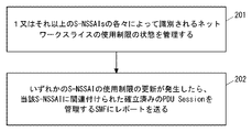
- FIG. 2 shows an example of the operation of AMF2.
- AMF2 manages the state of network slice restriction (NSR). Specifically, AMF2 manages whether there are restrictions on the use of network slices identified by each of one or more S-NSSAIs. Restrictions on the use of network slices include restrictions on the radio frequencies (e.g., frequency bands or subbands) that can use network slices, restrictions on wireless access technology (RAT) that can use network slices, and geography that can use network slices. It may include at least one of area restrictions, application restrictions that can use network slices, and priorities among multiple network slices.
- radio frequencies e.g., frequency bands or subbands
- RAT wireless access technology
- AMF2 is that an S-NSSAI is in an NSR state where it can only be used in one or more specific frequency bands, or it cannot be used in one or more specific frequency bands. You may recognize that you are in the NSR state.
- AMF2 is that an S-NSSAI is in an NSR state where it can only be used with one or more specific RATs, or it is in an NSR state where it cannot be used with one or more specific RATs. , May be recognized.
- AMF2 is that an S-NSSAI is in an NSR state where it can only be used in one or more geographic areas, or it cannot be used in one or more geographic areas. You may recognize that you are in the NSR state. Each geographic area may be a tracking area or a cell.
- AMF2 is that an S-NSSAI is in an NSR state where it is only available for a particular one or more application (or service), or it is a particular one or more. You may recognize that you are in an NSR state that is not available for your application (or service).
- AMF2 may recognize that multiple S-NSSAIs are in an NSR state where they have priority among multiple network slices (S-NSSAIs). For example, AMF2 may recognize that when a higher priority network slice is used by UE1, lower priority network slices cannot be used simultaneously by the same UE1. Alternatively, AMF2 may recognize that one S-NSSAI (network slice) is in an NSR state that cannot be used at the same time as another S-NSSAI (s) (network slice).
- AMF2 sends a report indicating the NSR status update to SMF3 when the restriction update for the use of a specific S-NSSAI occurs in UE1 (that is, the NSR status update of UE1).
- AMF2 may send the report to SMF3, which manages the established PDU Session of UE1 associated with the S-NSSAI.
- the report allows SMF3 to control the release or modification of established PDU Sessions associated with the S-NSSAI in response to NSR state updates.
- the report showing the update of the NSR status in step 202 may show the S-NSSAI and the NSR status for the S-NSSAI.
- the report may indicate that the NSR state is active, inactive, or unknown.
- the active state means that the use of the corresponding S-NSSAI is restricted.
- the inactive state means that the use of the corresponding S-NSSAI is not restricted.
- the unaware state means that it is not known whether or not the corresponding S-NSSAI is restricted.
- the report showing the update of the NSR status in step 202 may be provided to SMF3 via the Application Program Interface (API) of the event notification service (i.e., Namf_EventExposureService) provided by AMF2.
- SMF3 as an NF Service Consumer creates a new subscription when a subscription is needed to monitor at least one event related to the NSR state of at least one S-NSSAI. Request AMF2 to do so.
- the SMF3 includes an identifier that identifies a particular UE (or UE group) and a list of subscribed events (a list of e.g., S-NSSAI (s)) in the request to indicate the Subscription Target. If the request is accepted, AMF2 notifies SMF3 of the generation of event subscription. After that, when the event of the subscribed NSR status notification occurs, AMF2 sends the notification to SMF3.
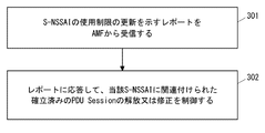
- FIG. 3 shows an example of the operation of SMF3.
- SMF3 receives a report from AMF2 indicating restrictions on the use of a particular S-NSSAI by UE1 (ie, updating the NSR state of UE1).
- SMF3 controls the release or modification of the established PDU Session of UE1 associated with the S-NSSAI in response to the report. For example, SMF3 may initiate the release of an established PDU Session or the deactivation of user plane resources for an established PDU Session if the report indicates that UE1 has restrictions on the use of network slices. SMF3 may also reject the modification of the established PDU session requested by UE1 if the report indicates that UE1 has restrictions on the use of network slices.
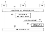
- FIG. 4 shows an example of the release procedure of the PDU Session started by SMF3.
- UE1 establishes a PDU Session.
- Step 401 may be performed according to an existing PDU session establishment procedure.
- AMF2 detects an update of UE1's NSR state for at least one S-NSSAI.
- AMF2 may detect that UE1 has moved from a geographic area where network slices are available to a geographic area where the use of network slices is restricted.
- the geographical area is a collection of Tracking Area Identity (TAI) (List of TAI), a collection of E-UTRAN Cell Global Identification (ECGI) (List of ECGI), or NR Cell Global Identity (NCGI).
- TAI Tracking Area Identity
- ECGI E-UTRAN Cell Global Identification
- NCGI NR Cell Global Identity
- the geographical area may be an Allowed Area, Non-Allowed Area, Forbidden Area, or Mobility Pattern defined in Non-Patent Document 2.
- AMF2 sends a report indicating the update of NSR status to SMF3.
- the report shows restrictions on the use of certain S-NSSAI by UE1 (ie, updating the NSR state of UE1).
- SMF3 decides to release UE1's established PDU Session for that S-NSSAI. do. More specifically, in step 404, the S-NSSAI associated with the established PDU Session is included in the report showing the update of the NSR state, and the NSR state limits its use because of the S-NSSAI. If SMF3 determines to release the established PDU Session, SMF3 determines to release the established PDU Session associated with the S-NSSAI.
- step 405 SMF3 starts the PDU Session release procedure.
- SMF3 sends a PDU SessionReleaseCommand message to UE1 via AMF2.
- the PDU SessionReleaseCommand message may include a new 5GSM cause value indicating that the use of S-NSSAI is restricted.
- the procedure of FIG. 4 may be modified as follows.
- step 404 if the report showing the NSR state update shows that UE1 has restrictions on the use of a particular S-NSSAI, then SMF3 is the user plane of UE1's established PDU Session for that S-NSSAI. You may decide to deactivate the resource.
- step 405 SMF3 may signal UPF6 to deactivate the user plane resource for the PDU Session.
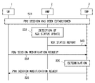
- FIG. 5 shows an example of the PDU Session Modification procedure.
- Steps 501 to 503 are the same as steps 401 to 403 in FIG.
- SMF3 receives a PPDU Session Modification Request message from UE1.
- the PDU Session Modification Request message requests modification of the PDU Session for a specific S-NSSAI.
- SMF3 determines that UE1 is restricted from using the S-NSSAI based on the report in step 503.
- SMF3 sends a PDU SessionModificationReject message to UE1.
- the PDU Session Modification Reject message may include a new 5GSM cause value indicating that the use of S-NSSAI is restricted. More specifically, in step 506, the S-NSSAI associated with the established PDUSession targeted by the PDUSessionModificationRequest message is included in the report indicating the update of the NSR state, and for the S-NSSAI. If the NSR state indicates that the use is restricted and SMF3 determines that the PDU Session Modification Request is rejected, SMF 3 sends a PDU Session Modification Reject message to UE1.
- AMF2 notifies SMF3 of the state of restriction on the use of a specific network slice by UE1. Then, SMF3 controls the release or modification of the established PDU Session of UE1 for the network slice in response to the notification from AMF2. This contributes to the realization of session management that adapts to the restrictions on the use of network slices.
- FIG. 6 shows an example of the release procedure of the PDU Session triggered by AMF2.
- the UE 1 establishes a PDU Session.
- Step 601 may be performed according to an existing PDU session establishment procedure.
- AMF2 detects an update of the NSR state of UE1 for at least one S-NSSAI.
- the operation of AMF2 in step 602 is similar to the corresponding operation described in the first embodiment (e.g., step 201 in FIG. 2, step 402 in FIG. 4).
- AMF2 detects that UE1 has restrictions on the use of a particular network slice (specific S-NSSAI).
- AMF2 requests SMF3 to release the established PDU Session of UE1 for that particular network slice.
- the request (or trigger) may include a Cause information element set to a new value (e.g., REL_DUE_TO_SLICE_NWRESTRICTION) to indicate to SMF3 that this is based on network rice usage restrictions.
- the SMF3 initiates the PDU Session Release procedure in response to the request (or trigger) of step 603.
- SMF3 sends a PDU SessionReleaseCommand message to UE1 via AMF2.
- the PDU SessionReleaseCommand message may include a new 5GSM cause value indicating that the use of S-NSSAI is restricted.
- step 604 SMF3 may initiate deactivation of the user plane resource of UE1's established PDU Session for the S-NSSAI. SMF3 may signal UPF6 to deactivate the user plane resource of the PDU Session.
- AMF2 releases the established PDU Session of UE1 for the network slice to SMF3. Request. This contributes to the realization of session management that adapts to the restrictions on the use of network slices.
- a NAS message ie, UL NAS Transport
- an SM message ie, PDU Session Establishment Request
- PDU Session Establishment Request requesting the establishment of a PDU Session associated with S-NSSAI that is not permitted to be used by UE1.
- FIG. 7 shows an example of signaling between UE1 and AMF2.
- FIG. 8 shows an example of the operation of AMF2.
- UE1 transmits a ULNAS Transport message including an N1 SM container (PDU Session Establishment Request) to AMF2 via AN5.
- AMF2 receives a ULNAS Transport message including a PDU SessionEstablishmentRequest message from UE1 (step 801).
- AMF2 manages whether there are restrictions on the use of network slices identified by each of one or more S-NSSAIs.
- Restrictions on the use of network slices include restrictions on the radio frequencies (e.g., frequency bands or subbands) that can use network slices, restrictions on wireless access technology (RAT) that can use network slices, and geography that can use network slices. It may include at least one of area restrictions, application restrictions that can use network slices, and priorities among multiple network slices.
- radio frequencies e.g., frequency bands or subbands
- RAT wireless access technology
- AMF2 is that an S-NSSAI is in an NSR state where it can only be used in one or more specific frequency bands, or it cannot be used in one or more specific frequency bands. You may recognize that you are in the NSR state.
- AMF2 is that an S-NSSAI is in an NSR state where it can only be used with one or more specific RATs, or it is in an NSR state where it cannot be used with one or more specific RATs. , May be recognized.
- AMF2 is that an S-NSSAI is in an NSR state where it can only be used in one or more geographic areas, or it cannot be used in one or more geographic areas. You may recognize that you are in the NSR state. Each geographic area may be a tracking area or a cell.
- AMF2 is that an S-NSSAI is in an NSR state where it is only available for a particular one or more application (or service), or it is a particular one or more. You may recognize that you are in an NSR state that is not available for your application (or service).
- AMF2 may recognize that multiple S-NSSAIs are in an NSR state where they have priority among multiple network slices (S-NSSAIs). For example, AMF2 may recognize that when a higher priority network slice is used by UE1, lower priority network slices cannot be used simultaneously by the same UE1. Alternatively, AMF2 may recognize that one S-NSSAI (network slice) is in an NSR state that cannot be used at the same time as another S-NSSAI (s) (network slice).
- AMF2 determines whether or not usage restrictions are imposed on the S-NSSAI associated with the PDU Session requested by UE1. In steps 703 and 803, if the S-NSSAI is subject to usage restrictions, AMF2 stops forwarding the PDU Session Establishment Request message to SMF 3 and rejects the UL NAS Transport message. As shown in step 703, AMF2 may send a DLNAS Transport message to UE1.
- the DL NAS Transport message may include a rejected N1 SM container (PDU Session Establishment Request).
- the DL NAS Transport message may include a message identifier, a message sequence number, or other identifier of the UL NAS Transport message in order to indicate the association with the rejected UL NAS Transport message.
- the DL NAS Transport message may indicate an existing 5GMM Cause value (e.g., 5GMM cause # 90 "payload was not forwarded"). Instead, the DLNAS Transport message may include a new 5GMM cause value indicating that SM messages are not forwarded due to slice usage restrictions.
- FIG. 9 shows an example of the operation of AMF2 and provides a modification of the operation shown in FIG.
- Step 901 is the same as step 801 of FIG.
- AMF2 receives a ULNAS Transport message including a PDU SessionEstablishmentRequest message from UE1.
- UE1 indicates support for network rice restriction (NSR).
- AMF2 may determine whether the received PDU Session Establishment Request message contains an indication of NSR support.
- AMF2 may determine if UE1 has indicated support for NSR during past registration procedures. More specifically, AMF2 may determine whether the context of UE1 stored in AMF2 indicates support for NSR.
- the display of NSR support may be UE1 capability information.
- Step 903 is the same as step 802 in FIG. AMF2 determines whether or not usage restrictions are imposed on the S-NSSAI associated with the PDU Session requested by UE1.
- the order of steps 902 and 903 is not limited to the order shown in FIG.
- the determination in step 902 may be performed after the determination in step 903, or may be performed at the same time as the determination in step 903.
- step 904 if UE1 does not indicate NSR support and the S-NSSAI is subject to usage restrictions, AMF2 stops forwarding the PDU Session Establishment Request message to SMF3 and the ULNAS Transport message. Reject.
- the AMF2 can reject the PDU Session establishment request regarding the slice with the usage restriction received from the UE (e.g. pre-Release 18 UE) that does not support NSR.
- the UE e.g. pre-Release 18 UE
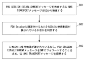
- FIG. 10 shows an example of the operation of AMF2 and provides a modification of the operation shown in FIG.
- Step 901 is the same as step 801 of FIG.
- AMF2 receives a ULNAS Transport message including a PDU SessionEstablishmentRequest message from UE1.
- AMF2 determines whether or not usage restrictions need to be imposed on the S-NSSAI associated with the PDU Session requested by UE1.
- step 903 if the S-NSSAI needs to be restricted, AMF2 stops forwarding the PDU SessionEstablishmentRequest message to SMF3 and rejects the ULNAS Transport message.
- the AMF2 when the AMF2 receives the PDU Session Establishment Request and the network slice usage restriction is enabled at the same time, the AMF2 promptly requests the PDU Session establishment for the network slice to which the usage restriction needs to be imposed. Can be rejected.
- FIG. 11 shows a modification of the signaling shown in FIG. 7.
- AMF2 may receive information about NSR from other network functions (Network Function (NF)) 1100.
- the NF1100 may be the NSSF4, UDM8, or UDR described above.
- the NF1100 may be any other of the 5GC's existing NFs, for example PolicyControlFunction (PCF) or NetworkDataAnalyticsFunction (NWDAF).
- PCF PolicyControlFunction
- NWDAF NetworkDataAnalyticsFunction
- the NF1100 may be a new network function of 5GC.
- AMF2 queries NF1100 for information about the NSR.
- AMF2 receives a report (e.g., NSR report) containing information about NSR from NF1100.
- a report e.g., NSR report
- AMF control the forwarding of SM messages (PDU Session Establishment Request messages) to SMF in consideration of restrictions on the use of network slices.
- FIG. 12 shows an example of signaling between UE1, AMF2, and SMF3.
- FIG. 13 shows an example of the operation of AMF2.
- Step 1201 is the same as step 701 in FIG.
- UE1 transmits a ULNAS Transport message including an N1 SM container (PDU Session Establishment Request) to AMF2 via AN5.
- AMF2 receives a ULNAS Transport message including a PDU SessionEstablishmentRequest message from UE1 (step 1301).
- AMF2 manages whether there are restrictions on the use of network slices identified by each of one or more S-NSSAIs.
- Restrictions on the use of network slices include restrictions on the radio frequencies (e.g., frequency bands or subbands) that can use network slices, restrictions on wireless access technology (RAT) that can use network slices, and geography that can use network slices. It may include at least one of area restrictions, application restrictions that can use network slices, and priorities among multiple network slices.
- radio frequencies e.g., frequency bands or subbands
- RAT wireless access technology
- AMF2 is that an S-NSSAI is in an NSR state where it can only be used in one or more specific frequency bands, or it cannot be used in one or more specific frequency bands. You may recognize that you are in the NSR state.
- AMF2 is that an S-NSSAI is in an NSR state where it can only be used with one or more specific RATs, or it is in an NSR state where it cannot be used with one or more specific RATs. , May be recognized.
- AMF2 is that an S-NSSAI is in an NSR state where it can only be used in one or more geographic areas, or it cannot be used in one or more geographic areas. You may recognize that you are in the NSR state. Each geographic area may be a tracking area or a cell.
- AMF2 is that an S-NSSAI is in an NSR state where it is only available for a particular one or more application (or service), or it is a particular one or more. You may recognize that you are in an NSR state that is not available for your application (or service).
- AMF2 may recognize that multiple S-NSSAIs are in an NSR state where they have priority among multiple network slices (S-NSSAIs). For example, AMF2 may recognize that when a higher priority network slice is used by UE1, lower priority network slices cannot be used simultaneously by the same UE1. Alternatively, AMF2 may recognize that one S-NSSAI (network slice) is in an NSR state that cannot be used at the same time as another S-NSSAI (network slice). Similar to the operation shown in FIG. 11, the AMF2 may receive information about the NSR from other network functions.
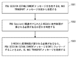
- AMF2 determines whether or not usage restrictions need to be imposed (or whether or not) are imposed on the S-NSSAI associated with the PDU Session requested by UE1. In steps 1203 and 1303, if the S-NSSAI needs (or is) restricted in use, AMF2 states that the establishment of the PDU Session should be rejected because of the restricted use. Forward the PDU Session Establishment message to SMF3 with the indication. Specifically, the AMF2 sends a control message (e.g., Nsmf_PDUSession_CreateSMContextRequest) including the PDUSessionEstablishment message and the display to the SMF3.
- the display may be, for example, "REJECT_DUE_TO_SLICE_NWRESTRICTION".
- the SMF3 rejects the establishment of the PDU Session if it receives the PDU Session Establishmentment message with an indication that the establishment of the PDU Session should be rejected due to usage restrictions.
- the SMF3 sends a PDU SessionEstablishmentReject message to UE1 via AMF2 (steps 1204 and 1205).
- the PDU SessionEstablishmentReject message may include a new 5GSM cause value indicating a slice usage limit.
- AMF2 and SMF3 can reject the request for establishing a PDU Session regarding a network slice for which usage restrictions are imposed. This contributes to the realization of session management that adapts to the restrictions on the use of network slices.
- FIG. 14 is a block diagram showing a configuration example of UE1.
- Radio Frequency (RF) transceiver 1401 performs analog RF signal processing to communicate with RAN nodes.
- the RF transceiver 1401 may include a plurality of transceivers.
- the analog RF signal processing performed by the RF transceiver 1401 includes frequency up-conversion, frequency down-conversion, and amplification.
- the RF transceiver 1401 is coupled with the antenna array 1402 and the baseband processor 1403.
- the RF transceiver 1401 receives modulation symbol data (or OFDM symbol data) from the baseband processor 1403, generates a transmit RF signal, and supplies the transmit RF signal to the antenna array 1402. Further, the RF transceiver 1401 generates a baseband reception signal based on the received RF signal received by the antenna array 1402, and supplies the baseband reception signal to the baseband processor 1403.
- the RF transceiver 1401 may include an analog beamformer circuit for beamforming.
- the analog beamformer circuit includes, for example, a plurality of phase shifters and a plurality of power amplifiers.
- the baseband processor 1403 performs digital baseband signal processing (data plane processing) and control plane processing for wireless communication.
- Digital baseband signal processing includes (a) data compression / restoration, (b) data segmentation / concatenation, (c) transmission format (transmission frame) generation / decomposition, and (d) transmission path coding / decoding. , (E) Modulation (symbol mapping) / demodulation, and (f) Generation of OFDM symbol data (baseband OFDM signal) by Inverse Fast Fourier Transform (IFFT).
- IFFT Inverse Fast Fourier Transform
- control plane processing includes layer 1 (e.g., transmission power control), layer 2 (e.g., radio resource management, and hybrid automatic repeat request (HARQ) processing), and layer 3 (e.g., attach, mobility, and call management). Includes communication management (signaling regarding).
- layer 1 e.g., transmission power control
- layer 2 e.g., radio resource management, and hybrid automatic repeat request (HARQ) processing
- layer 3 e.g., attach, mobility, and call management.
- Includes communication management (signaling regarding).
- digital baseband signal processing by the baseband processor 1403 includes a ServiceDataAdaptationProtocol (SDAP) layer, a PacketDataConvergenceProtocol (PDCP) layer, a RadioLinkControl (RLC) layer, a MediumAccessControl (MAC) layer, and a Physical. (PHY) layer signal processing may be included.
- SDAP ServiceDataAdaptationProtocol
- PDCP PacketDataConvergenceProtocol
- RLC RadioLinkControl
- MAC MediumAccessControl
- PHY Physical.
- control plane processing by the baseband processor 1403 may include the processing of the Non-Access Stratum (NAS) protocol, the Radio Resource Control (RRC) protocol, and the MAC Control Elements (CEs).
- NAS Non-Access Stratum
- RRC Radio Resource Control
- CEs MAC Control Elements
- the baseband processor 1403 may perform Multiple Input Multiple Output (MIMO) encoding and precoding for beamforming.
- MIMO Multiple Input Multiple Output
- the baseband processor 1403 includes a modem processor (e.g., Digital Signal Processor (DSP)) that performs digital baseband signal processing and a protocol stack processor (e.g., Central Processing Unit (CPU) or Micro Processing Unit (e.g., Central Processing Unit (CPU)) that performs control plane processing. MPU)) may be included.
- DSP Digital Signal Processor
- MPU Central Processing Unit
- the protocol stack processor that performs the control plane processing may be shared with the application processor 1404 described later.
- the application processor 1404 is also called a CPU, MPU, microprocessor, or processor core.
- the application processor 1404 may include a plurality of processors (a plurality of processor cores).
- the application processor 1404 is a system software program (Operating System (OS)) read from memory 1406 or a memory (not shown) and various application programs (eg, call application, web browser, mailer, camera operation application, music playback). By executing the application), various functions of UE1 are realized.
- OS Operating System
- the baseband processor 1403 and application processor 1404 may be integrated on one chip, as shown by the dashed line (1405) in FIG.
- the baseband processor 1403 and the application processor 1404 may be implemented as one System on Chip (SoC) device 1405.
- SoC devices are sometimes referred to as system Large Scale Integration (LSI) or chipsets.
- Memory 1406 is a volatile memory, a non-volatile memory, or a combination thereof.
- the memory 1406 may include a plurality of physically independent memory devices.
- the volatile memory is, for example, Static Random Access Memory (SRAM), Dynamic RAM (DRAM), or a combination thereof.
- the non-volatile memory is a mask ReadOnlyMemory (MROM), Electrically ErasableProgrammableROM (EEPROM), flash memory, or hard disk drive, or any combination thereof.
- the memory 1406 may include an external memory device accessible from the baseband processor 1403, the application processor 1404, and the SoC 1405.
- the memory 1406 may include an internal memory device integrated in the baseband processor 1403, in the application processor 1404, or in the SoC 1405. Further, the memory 1406 may include the memory in the Universal Integrated Circuit Card (UICC).
- UICC Universal Integrated Circuit Card
- the memory 1406 may store one or more software modules (computer programs) 1407 including instruction groups and data for performing processing by the UE 1 described in the plurality of embodiments described above.
- the baseband processor 1403 or application processor 1404 is configured to read the software module 1407 from the memory 1406 and execute it to perform the processing of UE1 described with reference to the drawings in the above embodiments. May be done.
- control plane processing and operation performed by UE1 described in the above-described embodiment is performed by at least one of the other elements except the RF transceiver 1401 and the antenna array 1402, that is, the baseband processor 1403 and the application processor 1404, and the software module 1407. It can be realized by the memory 1406 that stores the above.
- FIG. 15 shows a configuration example of AMF2.
- SMF3 may also have the configuration shown in FIG.
- AMF2 includes a network interface 1501, a processor 1502, and a memory 1503.
- the network interface 1501 is used, for example, to communicate with (R) AN nodes and to communicate with other network functions (NFs) or nodes within 5GC.
- Other NFs or nodes within the 5GC include, for example, UDM, AUSF, SMF, and PCF.
- the network interface 1501 may include, for example, a network interface card (NIC) compliant with the IEEE802.3 series.
- NIC network interface card
- the processor 1502 may be, for example, a microprocessor, a MicroProcessingUnit (MPU), or a CentralProcessingUnit (CPU). Processor 1502 may include a plurality of processors.
- MPU MicroProcessingUnit
- CPU CentralProcessingUnit
- the memory 1503 is composed of a volatile memory and a non-volatile memory.
- the memory 1503 may include a plurality of physically independent memory devices.
- the volatile memory is, for example, Static Random Access Memory (SRAM), Dynamic RAM (DRAM), or a combination thereof.
- the non-volatile memory is a mask ReadOnlyMemory (MROM), Electrically ErasableProgrammableROM (EEPROM), flash memory, or hard disk drive, or any combination thereof.
- the memory 1503 may include storage located away from the processor 1502. In this case, the processor 1502 may access the memory 1503 via the network interface 1501 or the I / O interface.
- the memory 1503 may store at least one software module (computer program) 1504 including the instruction group and data for performing the processing by the AMF2 described in the plurality of embodiments described above.
- the processor 1502 may be configured to read the software module 1504 from the memory 1503 and execute it to perform the processing of AMF2 described in the above embodiment.
- each of the processors included in UE1, AMF2, and SMF3 provides instructions for causing the computer to perform the algorithm described with reference to the drawings.
- This program is stored using various types of non-transitory computer readable medium and can be supplied to a computer.
- Non-temporary computer-readable media include various types of tangible storage mediums.
- non-temporary computer readable media are magnetic recording media (eg flexible disks, magnetic tapes, hard disk drives), magneto-optical recording media (eg magneto-optical disks), CompactDiscReadOnlyMemory (CD-ROM), CD- Includes R, CD-R / W, semiconductor memory (eg, mask ROM, Programmable ROM (PROM), Erasable PROM (EPROM), flash ROM, Random Access Memory (RAM)).
- the program may also be supplied to the computer by various types of transient computer readable medium.
- Examples of temporary computer readable media include electrical, optical, and electromagnetic waves.
- the temporary computer-readable medium can supply the program to the computer via a wired communication path such as an electric wire and an optical fiber, or a wireless communication path.
- (Appendix A1) A core network node for mobility management With at least one memory With at least one processor coupled to the at least one memory, Equipped with The at least one processor releases the established PDU Session associated with the network slice or deactivates the user plane resource of the established PDU Session in response to an update of the restriction on the use of the network slice. Configured to request core network nodes for session management, Core network node for mobility management. (Appendix A2)
- the restrictions include limits on the radio frequencies that can use the network slices, limits on the radio access technology that can use the network slices, limits on the geographic areas where the network slices can be used, and applications where the network slices can be used. Includes at least one of the limits of, and the priority-based limits between multiple network slices.
- the core network node for mobility management according to the appendix A1.
- Appendix A3 A method performed by core network nodes for mobility management, Releasing the established PDU Session associated with the network slice or deactivating the user plane resource of the established PDU Session in response to an update of the restriction on the use of the network slice, the core network node for session management. Be prepared to request Method.
- Appendix B1 A core network node for mobility management With at least one memory With at least one processor coupled to the at least one memory, Equipped with The at least one processor A first Non-Access Stratum (NAS) message containing a Session Management (SM) message requesting the establishment of a PDU Session is received from the User Equipment (UE).
- NAS Non-Access Stratum
- SM Session Management
- the usage restrictions include restrictions on the radio frequencies that can use network slices, restrictions on wireless access technologies that can use network slices, restrictions on geographic areas that can use network slices, and restrictions on applications that can use network slices. And a priority-based limit between multiple network slices, including at least one. Core network node for mobility management.
- the at least one processor sends the SM message to the core network node for session management if the UE does not indicate support for network slice restrictions and the network slice identifier is subject to the usage restrictions. Stop forwarding and reject the NAS message, The core network node for mobility management described in Appendix B1.
- the at least one processor is configured to send a second NAS message to the UE, including a cause value indicating that the SM message is not forwarded due to the usage restrictions.
- the at least one processor is configured to receive information indicating the usage restriction from other network functions.
- Appendix B5 A method performed by core network nodes for mobility management, Receiving a first Non-Access Stratum (NAS) message from the User Equipment (UE) that includes a Session Management (SM) message requesting the establishment of a PDU Session. Determining if the network slice identifier associated with the PDU Session is or should be restricted, and whether the network slice identifier is subject to or should be restricted. Stop forwarding the SM message to the core network node for session management and reject the NAS message if it needs to be imposed. Equipped with The usage restrictions include restrictions on the radio frequencies that can use network slices, restrictions on wireless access technologies that can use network slices, restrictions on geographic areas that can use network slices, and restrictions on applications that can use network slices.
- NAS Non-Access Stratum
- UE User Equipment
- SM Session Management
- Method. A program for causing a computer to perform a method for a core network node for mobility management, wherein the method is Receiving a first Non-Access Stratum (NAS) message from the User Equipment (UE) that includes a Session Management (SM) message requesting the establishment of a PDU Session. Determining if the network slice identifier associated with the PDU Session is or should be restricted, and whether the network slice identifier is subject to or is subject to such restrictions. Stop forwarding the SM message to the core network node for session management and reject the NAS message if it needs to be imposed.
- NAS Non-Access Stratum
- UE User Equipment
- SM Session Management
- the usage restrictions include restrictions on the radio frequencies that can use network slices, restrictions on wireless access technologies that can use network slices, restrictions on geographic areas that can use network slices, and restrictions on applications that can use network slices. And a priority-based limit between multiple network slices, including at least one. program.
- Appendix C1 A core network node for mobility management With at least one memory With at least one processor coupled to the at least one memory, Equipped with The at least one processor Receive a Non-Access Stratum (NAS) message from the User Equipment (UE) that contains a Session Management (SM) message requesting the establishment of a PDU Session. Determine if the network slice identifier associated with the PDU Session is or should be restricted.
- NAS Non-Access Stratum
- UE User Equipment
- SM Session Management
- the usage restrictions include restrictions on the radio frequencies that can use network slices, restrictions on wireless access technologies that can use network slices, restrictions on geographic areas that can use network slices, and restrictions on applications that can use network slices. And a priority-based limit between multiple network slices, including at least one.
- Core network node for mobility management. (Appendix C2)
- the at least one processor is configured to receive information indicating the usage restriction from other network functions.
- a control message containing a first Session Management (SM) message requesting the establishment of a PDU Session for User Equipment (UE) is received from the core network node for mobility management. If the control message contains an indication that the establishment of the PDU Session should be rejected due to usage restrictions, the establishment of the PDU Session is rejected.
- the usage restrictions include restrictions on the radio frequencies that can use network slices, restrictions on wireless access technologies that can use network slices, restrictions on geographic areas that can use network slices, and restrictions on applications that can use network slices. And a priority-based limit between multiple network slices, including at least one.
- Core network node for session management The at least one processor sends a second SM message containing a cause value indicating that the establishment of the PDU Session is rejected due to the usage restriction to the UE via the core network node for mobility management.
- Appendix C5 A method performed by core network nodes for mobility management, Receiving a Non-Access Stratum (NAS) message from User Equipment (UE), including a Session Management (SM) message requesting the establishment of a PDU Session, Determining if the network slice identifier associated with the PDU Session is or should be restricted, and whether the network slice identifier is subject to or should be restricted.
- NAS Non-Access Stratum
- UE User Equipment
- SM Session Management
- Method. It is a method performed by the core network node for session management. Receiving a control message from a core network node for mobility management, including a first Session Management (SM) message requesting the establishment of a PDU Session for User Equipment (UE), and the establishment of the PDU Session used.
- SM Session Management
- the usage restrictions include restrictions on the radio frequencies that can use network slices, restrictions on wireless access technologies that can use network slices, restrictions on geographic areas that can use network slices, and restrictions on applications that can use network slices. And a priority-based limit between multiple network slices, including at least one. Method.
- the at least one processor is configured to reject the modification of the established PDU session requested by the UE if the report indicates that the use of the network slice is limited.
- the core network node for session management according to Appendix 1 or 2.
- the report contains information indicating whether the restrictions on the use of the network slices are activated, deactivated or unknown.
- the at least one processor is configured to control the release or modification of the established PDU Session associated with the network slice when the information indicates that the restriction has been activated.
- the core network node for session management according to any one of Supplementary note 1 to 3.
- the at least one processor A request to join the notification service regarding restrictions on the use of the network slice by the UE is transmitted to the core network node for mobility management.
- a core network node for mobility management With at least one memory With at least one processor coupled to the at least one memory, Equipped with The at least one processor is configured to send a report indicating that the limit update has occurred to the core network node for session management in response to the user equipment (UE) updating the limit for the use of the network slice. Be done, Core network node for mobility management.
- the restrictions include limits on the radio frequencies that can use the network slices, limits on the radio access technology that can use the network slices, limits on the geographic areas where the network slices can be used, and applications where the network slices can be used.
- the core network node for mobility management includes at least one of the limits of, and the priority-based limits between multiple network slices.
- the core network node for mobility management according to Appendix 6. The report contains information indicating whether the restriction on the use of the network slice is activated, deactivated or unknown.
- the core network node for mobility management according to Appendix 6 or 7. The at least one processor
- a request to join the notification service regarding the restriction on the use of the network slice by the UE is received from the core network node for session management. It is configured to send a report corresponding to the request to the core network node for session management.
- the core network node for mobility management according to any one of Supplementary note 6 to 8. (Appendix 10) It is a method performed by the core network node for session management.
- a method performed by core network nodes for mobility management In response to a limit update for the use of network slices by the User Equipment (UE), it comprises sending a report to the core network node for session management that the limit update has occurred.
- (Appendix 12) A program that causes a computer to perform a method for a core network node for session management, wherein the method is Receiving a report from the core network node for mobility management indicating that a restriction update for the use of the network slice by the User Equipment (UE) has occurred, and being associated with the network slice in response to receiving the report. Controlling the release or modification of the established PDU Session of the UE, The program.
- (Appendix 13) A program that lets computers do the methods for core network nodes for mobility management. The method comprises sending a report indicating that the limit update has occurred to the core network node for session management in response to the limit update for the use of the network slice by the User Equipment (UE). program.
Landscapes
- Engineering & Computer Science (AREA)
- Computer Networks & Wireless Communication (AREA)
- Signal Processing (AREA)
- Computer Security & Cryptography (AREA)
- Mobile Radio Communication Systems (AREA)
Abstract
L'invention concerne un nœud de réseau central (3) pour la gestion de session qui reçoit, d'un nœud de réseau central (2) pour la gestion de mobilité, un rapport indiquant que des restrictions sur l'utilisation d'une tranche de réseau par UE (1) ont été mises à jour. En réponse à la réception du rapport, le nœud de réseau central (3) pour la gestion de session commande l'analyse ou la correction d'une session PDU établie pour l'UE (1) qui est associé à la tranche de réseau. Cela peut contribuer par exemple à la réalisation d'une gestion de session qui est adaptée aux restrictions sur l'utilisation d'une tranche de réseau.
Priority Applications (3)
| Application Number | Priority Date | Filing Date | Title |
|---|---|---|---|
| JP2022556447A JPWO2022080017A1 (fr) | 2020-10-16 | 2021-08-26 | |
| US18/012,044 US20230247527A1 (en) | 2020-10-16 | 2021-08-26 | Core network node for session management, core network node for mobility management, and method therefor |
| EP21879759.5A EP4149203A4 (fr) | 2020-10-16 | 2021-08-26 | Noeud de réseau central pour la gestion de session, noeud de réseau central pour la gestion de mobilité, et procédé impliquant ceux-ci |
Applications Claiming Priority (2)
| Application Number | Priority Date | Filing Date | Title |
|---|---|---|---|
| JP2020-174588 | 2020-10-16 | ||
| JP2020174588 | 2020-10-16 |
Publications (1)
| Publication Number | Publication Date |
|---|---|
| WO2022080017A1 true WO2022080017A1 (fr) | 2022-04-21 |
Family
ID=81208307
Family Applications (1)
| Application Number | Title | Priority Date | Filing Date |
|---|---|---|---|
| PCT/JP2021/031366 WO2022080017A1 (fr) | 2020-10-16 | 2021-08-26 | Nœud de réseau central pour la gestion de session, nœud de réseau central pour la gestion de mobilité, et procédé impliquant ceux-ci |
Country Status (4)
| Country | Link |
|---|---|
| US (1) | US20230247527A1 (fr) |
| EP (1) | EP4149203A4 (fr) |
| JP (1) | JPWO2022080017A1 (fr) |
| WO (1) | WO2022080017A1 (fr) |
Citations (2)
| Publication number | Priority date | Publication date | Assignee | Title |
|---|---|---|---|---|
| US20200322857A1 (en) * | 2017-11-19 | 2020-10-08 | Lg Electronics Inc. | Handover method in wireless communication system and apparatus therefor |
| JP2020174588A (ja) | 2019-04-18 | 2020-10-29 | 株式会社Adeka | 油脂分解物 |
Family Cites Families (3)
| Publication number | Priority date | Publication date | Assignee | Title |
|---|---|---|---|---|
| US20200413241A1 (en) * | 2018-02-19 | 2020-12-31 | Lg Electronics Inc. | Method for terminal setting update in wireless communication system and apparatus therefor |
| US10506506B2 (en) * | 2018-04-30 | 2019-12-10 | Ofinno, Llc | 5G policy control for restricted local operator services |
| US11963247B2 (en) * | 2019-11-07 | 2024-04-16 | Qualcomm Incorporated | Handling slice limitations |
-
2021
- 2021-08-26 EP EP21879759.5A patent/EP4149203A4/fr active Pending
- 2021-08-26 JP JP2022556447A patent/JPWO2022080017A1/ja active Pending
- 2021-08-26 WO PCT/JP2021/031366 patent/WO2022080017A1/fr unknown
- 2021-08-26 US US18/012,044 patent/US20230247527A1/en active Pending
Patent Citations (2)
| Publication number | Priority date | Publication date | Assignee | Title |
|---|---|---|---|---|
| US20200322857A1 (en) * | 2017-11-19 | 2020-10-08 | Lg Electronics Inc. | Handover method in wireless communication system and apparatus therefor |
| JP2020174588A (ja) | 2019-04-18 | 2020-10-29 | 株式会社Adeka | 油脂分解物 |
Non-Patent Citations (8)
| Title |
|---|
| "3rd Generation Partnership Project; Technical Specification Group Services and System Aspects; System architecture for the 5G System (5GS); Stage 2 (Release 16", 3GPP TS 23.501, September 2020 (2020-09-01) |
| "New WID on Study on Enhanced Access to and Support of Network Slice (from S1-202284", 3GPP SA WG1, 30 June 2020 (2020-06-30) |
| ERICSSON: "KI#4 – Solution #2, Clarification on EN to check with SA5, and alignment with eNS_ph2", 3GPP DRAFT; S2-2007117, 3RD GENERATION PARTNERSHIP PROJECT (3GPP), MOBILE COMPETENCE CENTRE ; 650, ROUTE DES LUCIOLES ; F-06921 SOPHIA-ANTIPOLIS CEDEX ; FRANCE, vol. SA WG2, no. e-meeting; 20201012 - 20201023, 2 October 2020 (2020-10-02), Mobile Competence Centre ; 650, route des Lucioles ; F-06921 Sophia-Antipolis Cedex ; France , XP051938174 * |
| LG ELECTRONICS INC.: "WID on Study on Network Slice-aware Network Selection", 3GPP DRAFT; S1-201029, 3RD GENERATION PARTNERSHIP PROJECT (3GPP), MOBILE COMPETENCE CENTRE ; 650, ROUTE DES LUCIOLES ; F-06921 SOPHIA-ANTIPOLIS CEDEX ; FRANCE, vol. SA WG1, no. 20200210 - 20200214, 6 February 2020 (2020-02-06), Mobile Competence Centre ; 650, route des Lucioles ; F-06921 Sophia-Antipolis Cedex ; France , XP051846916 * |
| NEC, APPLE: "KI#2 Sol#10: Updates to Solution #10 Max number of PDU Sessions per Network Slice control", 3GPP DRAFT; S2-2003625, 3RD GENERATION PARTNERSHIP PROJECT (3GPP), MOBILE COMPETENCE CENTRE ; 650, ROUTE DES LUCIOLES ; F-06921 SOPHIA-ANTIPOLIS CEDEX ; FRANCE, vol. SA WG2, no. Electronic, Elbonia; 20200601 - 20200612, 22 May 2020 (2020-05-22), Mobile Competence Centre ; 650, route des Lucioles ; F-06921 Sophia-Antipolis Cedex ; France , XP051889683 * |
| NEC: "KI#6 Sol#27: Solution #27 clarification update", 3GPP DRAFT; S2-2007726, 3RD GENERATION PARTNERSHIP PROJECT (3GPP), MOBILE COMPETENCE CENTRE ; 650, ROUTE DES LUCIOLES ; F-06921 SOPHIA-ANTIPOLIS CEDEX ; FRANCE, vol. SA WG2, no. E (e-meeting); 20201012 - 20201023, 2 October 2020 (2020-10-02), Mobile Competence Centre ; 650, route des Lucioles ; F-06921 Sophia-Antipolis Cedex ; France , XP051938756 * |
| See also references of EP4149203A4 |
| SPIRENT COMM., AT&T, CONVIDA WIRELESS, SANDVINE: "KI #9, Solution Completion and Procedures: Dispersion Analytic Output Provided by NWDAF", 3GPP DRAFT; S2-2006977, 3RD GENERATION PARTNERSHIP PROJECT (3GPP), MOBILE COMPETENCE CENTRE ; 650, ROUTE DES LUCIOLES ; F-06921 SOPHIA-ANTIPOLIS CEDEX ; FRANCE, vol. SA WG2, no. Elbonia; 20201012 - 20201023, 2 October 2020 (2020-10-02), Mobile Competence Centre ; 650, route des Lucioles ; F-06921 Sophia-Antipolis Cedex ; France , XP051939007 * |
Also Published As
| Publication number | Publication date |
|---|---|
| EP4149203A4 (fr) | 2023-12-06 |
| EP4149203A1 (fr) | 2023-03-15 |
| US20230247527A1 (en) | 2023-08-03 |
| JPWO2022080017A1 (fr) | 2022-04-21 |
Similar Documents
| Publication | Publication Date | Title |
|---|---|---|
| US20220264505A1 (en) | Amf apparatus, ue, and methods therefor | |
| WO2019196643A1 (fr) | Procédé de communication et appareil de communication | |
| WO2021200239A1 (fr) | Dispositif amf, nœud de réseau d'accès et procédé associé | |
| US20220264679A1 (en) | Ue, af apparatus, smf apparatus, and methods thereof | |
| WO2021199582A1 (fr) | Dispositif de nœud de réseau d'accès sans fil, ue et procédé associé | |
| US20220295363A1 (en) | Pcf apparatus, af apparatus, nef apparatus, and methods thereof | |
| WO2021199581A1 (fr) | Dispositif de nœud de réseau à accès sans fil, dispositif amf et procédé associé | |
| US20220360969A1 (en) | Communication method and apparatus | |
| WO2022080017A1 (fr) | Nœud de réseau central pour la gestion de session, nœud de réseau central pour la gestion de mobilité, et procédé impliquant ceux-ci | |
| US20220022023A1 (en) | Method and Apparatus for Selecting Session Management Network Element | |
| AU2021423918A1 (en) | Communication method and apparatus | |
| JP7473001B2 (ja) | コアネットワークノード、端末、及びこれらの方法 | |
| WO2022080016A1 (fr) | Ue, nœud de réseau central, nœud, et procédés associés | |
| CN113329392A (zh) | 家庭网关接入网络的方法和通信装置 | |
| WO2023051428A1 (fr) | Procédé et appareil de transmission d'informations | |
| WO2023051427A1 (fr) | Procédé et appareil de communication | |
| WO2023160394A1 (fr) | Procédé et appareil de communication |
Legal Events
| Date | Code | Title | Description |
|---|---|---|---|
| 121 | Ep: the epo has been informed by wipo that ep was designated in this application |
Ref document number: 21879759 Country of ref document: EP Kind code of ref document: A1 |
|
| ENP | Entry into the national phase |
Ref document number: 2022556447 Country of ref document: JP Kind code of ref document: A |
|
| ENP | Entry into the national phase |
Ref document number: 2021879759 Country of ref document: EP Effective date: 20221208 |
|
| NENP | Non-entry into the national phase |
Ref country code: DE |