WO2022080017A1 - Core network node for session management, core network node for mobility management, and method involving same - Google Patents
Core network node for session management, core network node for mobility management, and method involving same Download PDFInfo
- Publication number
- WO2022080017A1 WO2022080017A1 PCT/JP2021/031366 JP2021031366W WO2022080017A1 WO 2022080017 A1 WO2022080017 A1 WO 2022080017A1 JP 2021031366 W JP2021031366 W JP 2021031366W WO 2022080017 A1 WO2022080017 A1 WO 2022080017A1
- Authority
- WO
- WIPO (PCT)
- Prior art keywords
- restrictions
- core network
- network node
- network
- pdu session
- Prior art date
Links
- 238000000034 method Methods 0.000 title claims description 64
- 230000004044 response Effects 0.000 claims abstract description 27
- 230000015654 memory Effects 0.000 claims description 69
- 238000005516 engineering process Methods 0.000 claims description 31
- 238000012986 modification Methods 0.000 claims description 28
- 230000004048 modification Effects 0.000 claims description 28
- 230000006870 function Effects 0.000 claims description 26
- 230000009849 deactivation Effects 0.000 claims description 4
- 238000007726 management method Methods 0.000 description 111
- 101100477785 Saccharomyces cerevisiae (strain ATCC 204508 / S288c) SMF3 gene Proteins 0.000 description 54
- 238000012545 processing Methods 0.000 description 24
- 238000004891 communication Methods 0.000 description 17
- 238000010586 diagram Methods 0.000 description 9
- 230000011664 signaling Effects 0.000 description 9
- 210000000623 ulna Anatomy 0.000 description 8
- 229910008956 UPF6 Inorganic materials 0.000 description 5
- 230000005540 biological transmission Effects 0.000 description 4
- 238000013523 data management Methods 0.000 description 4
- 238000013475 authorization Methods 0.000 description 3
- 238000013507 mapping Methods 0.000 description 3
- 101100348958 Caenorhabditis elegans smf-3 gene Proteins 0.000 description 2
- 241000209094 Oryza Species 0.000 description 2
- 235000007164 Oryza sativa Nutrition 0.000 description 2
- 230000001413 cellular effect Effects 0.000 description 2
- 238000006243 chemical reaction Methods 0.000 description 2
- 238000004590 computer program Methods 0.000 description 2
- 230000006855 networking Effects 0.000 description 2
- 235000009566 rice Nutrition 0.000 description 2
- 230000003068 static effect Effects 0.000 description 2
- 101150119040 Nsmf gene Proteins 0.000 description 1
- 230000003321 amplification Effects 0.000 description 1
- 230000006399 behavior Effects 0.000 description 1
- 230000010267 cellular communication Effects 0.000 description 1
- 239000000919 ceramic Substances 0.000 description 1
- 238000013144 data compression Methods 0.000 description 1
- 238000000354 decomposition reaction Methods 0.000 description 1
- 238000013461 design Methods 0.000 description 1
- 230000000694 effects Effects 0.000 description 1
- 230000002708 enhancing effect Effects 0.000 description 1
- 230000010354 integration Effects 0.000 description 1
- 238000010295 mobile communication Methods 0.000 description 1
- 238000003199 nucleic acid amplification method Methods 0.000 description 1
- 230000003287 optical effect Effects 0.000 description 1
- 239000013307 optical fiber Substances 0.000 description 1
- 230000000737 periodic effect Effects 0.000 description 1
- 230000011218 segmentation Effects 0.000 description 1
- 239000004065 semiconductor Substances 0.000 description 1
- 238000012546 transfer Methods 0.000 description 1
- 230000001052 transient effect Effects 0.000 description 1
- 230000001960 triggered effect Effects 0.000 description 1
Images


Classifications
-
- H—ELECTRICITY
- H04—ELECTRIC COMMUNICATION TECHNIQUE
- H04W—WIRELESS COMMUNICATION NETWORKS
- H04W48/00—Access restriction; Network selection; Access point selection
- H04W48/02—Access restriction performed under specific conditions
- H04W48/04—Access restriction performed under specific conditions based on user or terminal location or mobility data, e.g. moving direction, speed
-
- H—ELECTRICITY
- H04—ELECTRIC COMMUNICATION TECHNIQUE
- H04W—WIRELESS COMMUNICATION NETWORKS
- H04W24/00—Supervisory, monitoring or testing arrangements
- H04W24/02—Arrangements for optimising operational condition
-
- H—ELECTRICITY
- H04—ELECTRIC COMMUNICATION TECHNIQUE
- H04L—TRANSMISSION OF DIGITAL INFORMATION, e.g. TELEGRAPHIC COMMUNICATION
- H04L41/00—Arrangements for maintenance, administration or management of data switching networks, e.g. of packet switching networks
- H04L41/40—Arrangements for maintenance, administration or management of data switching networks, e.g. of packet switching networks using virtualisation of network functions or resources, e.g. SDN or NFV entities
-
- H—ELECTRICITY
- H04—ELECTRIC COMMUNICATION TECHNIQUE
- H04W—WIRELESS COMMUNICATION NETWORKS
- H04W76/00—Connection management
- H04W76/20—Manipulation of established connections
- H04W76/22—Manipulation of transport tunnels
-
- H—ELECTRICITY
- H04—ELECTRIC COMMUNICATION TECHNIQUE
- H04W—WIRELESS COMMUNICATION NETWORKS
- H04W76/00—Connection management
- H04W76/30—Connection release
- H04W76/32—Release of transport tunnels
-
- H—ELECTRICITY
- H04—ELECTRIC COMMUNICATION TECHNIQUE
- H04W—WIRELESS COMMUNICATION NETWORKS
- H04W76/00—Connection management
- H04W76/30—Connection release
- H04W76/34—Selective release of ongoing connections
-
- H—ELECTRICITY
- H04—ELECTRIC COMMUNICATION TECHNIQUE
- H04W—WIRELESS COMMUNICATION NETWORKS
- H04W88/00—Devices specially adapted for wireless communication networks, e.g. terminals, base stations or access point devices
- H04W88/14—Backbone network devices
Definitions
- This disclosure relates to wireless communication networks, especially network slicing.
- Network slicing makes it possible to create multiple logical networks or unvirtualized logical networks on top of physical networks.
- Network slicing may use Network Function Virtualization (NFV) technology and software-defined networking (SDN) technology to create multiple virtualized logical networks on top of a physical network. ..
- NFV Network Function Virtualization
- SDN software-defined networking
- Each logical network is called a network slice.
- Network slices provide specific network capabilities and network characteristics.
- a network slice instance (NSI) is a network function (NF) instance and resources (e.g., computer processing resources, storage, and storage) to form a single network slice.
- Networking resources and one or both of the access network (AN) (Next Generation Radio Access Network (NG-RAN) and Non-3GPP InterWorking Function (N3IWF)).
- AN Next Generation Radio Access Network
- N3IWF Non-3GPP InterWorking Function
- S-NSSAI Single Network Slice Selection Assistance Information
- SST Slice / Service type
- SD Slice Differentiator
- SST means referreds to expected network slice behavior with respect to features and services.
- SD is optional information and complements SST to distinguish between multiple network slices of the same Slice / Service type.
- S-NSSAI can have standard values or non-standard values.
- Standard SST values 1, 2, 3, and 4 are enhanced Mobile Broad Band (eMBB), Ultra Reliable and Low Latency Communication (URLLC), Massive Internet of Things (MIoT), and Vehicle to Everything (V2X). It is associated with slice types.
- the non-standard value of S-NSSAI identifies one network slice within a particular Public Land Mobile Network (PLMN). That is, non-standard SST values are PLMN-specific values and are associated with the PLMN ID of the PLMN to which they are assigned.
- PLMN Public Land Mobile Network
- Each S-NSSAI guarantees network independence in choosing a particular NSI.
- the same NSI may be selected via different S-NSSAIs.
- the same S-NSSAI may be associated with different NSIs.
- Each network slice may be uniquely identified by S-NSSAI.
- S-NSSAI There are two types of S-NSSAI, which are known as S-NSSAI and Mapped S-NSSAI.
- S-NSSAI identifies the network slice provided by the serving Public Land Mobile Network (PLMN) to which the UE connects. Therefore, when the home network is in the area, S-NSSAI identifies the network slice of the home network (e.g., Home PLMN (HPLMN)).
- PLMN Public Land Mobile Network
- S-NSSAI identifies the network slice of the roaming network (e.g., Visited PLMN (VPLMN)).
- PLMN Public Land Mobile Network
- VPN Visited PLMN
- Mapped S-NSSAI is a Home PLMN (HPLMN) S-NSSAI that is mapped (associated or applicable) to the S-NSSAI that identifies the network slice of the roaming network when the UE is roaming. It may be S-NSSAI included in the subscriber information of the UE user.
- HPLMN Home PLMN
- S-NSSAI included in the subscriber information of the UE user.
- NSSAI Network Slice Selection Assistance Information
- Configured NSSAI Requested NSSAI
- Allowed NSSAI Rejected NSSAI
- Pending NSSAI Pending NSSAI
- Configured NSSAI includes at least one S-NSSAI, each applicable to at least one PLMN.
- the Configured NSSAI is set by, for example, the Serving PLMN and is applied to the Serving PLMN.
- the Configured NSSAI may be the Default Configured NSSAI.
- the Default Configured NSSAI is set by the Home PLMN (HPLMN) and applies to any (any) PLMNs for which no specific (specific) Configured NSSAI is provided.
- Default Configured NSSAI is provisioned from Unified Data Management (UDM) of HPLMN to a wireless terminal (User Equipment (UE)) via Access and Mobility Management Function (AMF), for example.
- UDM Unified Data Management
- UE User Equipment
- AMF Access and Mobility Management Function
- the Requested NSSAI is signaled to the network by the UE, for example, in a registration procedure, allowing the network to determine a Serving AMF, at least one network slice, and at least one NSI for that UE.
- Allowed NSSAI indicates at least one S-NSSAI provided to the UE by the Serving PLMN and can be used by the UE in the current Registration Area (RA) of the Serving PLMN. Allowed NSSAI is determined by the AMF of the Serving PLMN, for example, during the registration procedure. Allowed NSSAI is signaled to the UE by the network (i.e., AMF) and stored in the respective memories (e.g., non-volatile) of the AMF and the UE.
- the network i.e., AMF
- memories e.g., non-volatile
- Rejected NSSAI includes at least one S-NSSAI rejected by the current (current) PLMN.
- Rejected NSSAI is sometimes called rejected S-NSSAIs.
- S-NSSAI is either rejected by the current PLMN as a whole or rejected by the current (current) registration area (RA). If the AMF rejects any one of at least one S-NSSAI included in the Requested NSSAI, for example, in the registration procedure of the UE, these are included in the Rejected NSSAI.
- the Rejected NSSAI is signaled to the UE by the network (i.e., AMF) and stored in the respective memories of the AMF and the UE.
- Pending NSSAI indicates at least one S-NSSAI for which authentication and authorization (Network Slice-Specific Authentication and Authorization (NSSAA)) specialized for network slices are pending.
- the Serving PLMN must perform NSSAA on the HPLMN's S-NSSAI (s), which is subject to NSSAA based on subscription information.
- AMF implements Extensible Authentication Protocol (EAP) -based authorization procedure (invoke). EAP-based authentication procedure takes a relatively long time to obtain the result (outcome).
- EAP Extensible Authentication Protocol
- AMF determines Allowed NSSAI as described above in the registration procedure of UE, but does not include S-NSSAI (s) imposed by NSSAA in the Allowed NSSAI, and instead includes them in Pending NSSAI. Include in. Pending NSSAI is signaled to the UE by the network (i.e., AMF) and stored in the respective memories of AMF and UE.
- AMF the network
- the 3rd Generation Partnership Project (3GPP) is considering enhancing network slice functions for Release 17.
- 3GPP Technical Specification Group Services and System Aspects (TSG-SA) Working Group 1 (WG1) is for Release 18 to investigate the feasibility of Enhanced Access to Support of Network Slice.
- Approved a new working / study item (see Non-Patent Document 1).
- One of the objectives of this study item is to limit network slices to certain frequency bands / subbands, RadioAccess Technologies (RATs), geographic areas, networks, applications, etc. Identifying various deployments and usage scenarios of network slices, when there is a restriction of network slices to e.g., ceramic frequency bands / subbands, RATs, geographical areas ..
- UE User Equipment
- RATs RadioAccess Technologies
- 3GPP SA WG1 "New WID on Study on Enhanced Access to and Support of Network Slice (from S1-202284)", SP-200571, 3GPP TSG SA Meeting # 88e, Electronic Meeting, June 30th-July 3GPP TS 23.501 V16.6.0 (2020-09) “3rd Generation Partnership Project; Technical Specification Group Services and System Aspects; System architecture for the 5G System (5GS); Stage 2 (Release 16)”, September 2020
- One of the objectives to be achieved by the embodiments disclosed herein is to provide devices, methods, and programs that contribute to the realization of session management adapted to the restrictions on the use of network slices. It should be noted that this object is only one of the purposes that the plurality of embodiments disclosed herein seek to achieve. Other objectives or issues and novel features will be apparent from the description or accompanying drawings herein.
- the core network node for session management includes at least one memory and at least one processor coupled to the at least one memory.
- the at least one processor is configured to receive a report from the core network node for mobility management indicating that a restriction update for the use of network slices by the UE has occurred.
- the at least one processor is further configured to control the release or modification of the established PDU Session of the UE associated with the network slice in response to receiving the report.
- the core network node for mobility management includes at least one memory and at least one processor coupled to the at least one memory.
- the at least one processor is configured to send a report indicating that the limit update has occurred to the core network node for session management in response to the limit update for the use of network slices by the UE.
- the method performed by the core network node for session management includes the following steps: (A) receive a report from the core network node for mobility management indicating that a restriction update for the use of network slices by the UE has occurred, and (b) said at least one processor further receives the report. To control the release or modification of the established PDU Session of the UE associated with the network slice in response to.
- the method performed by the core network node for mobility management is to report for session management that the limit update has occurred in response to the limit update for the use of network slices by the UE. Includes sending to core network nodes.
- the core network node for mobility management includes at least one memory and at least one processor coupled to the at least one memory.
- the at least one processor releases the established PDU Session associated with the network slice or deactivates the user plane resource of the established PDU Session in response to an update of the restriction on the use of the network slice. Configured to request the core network node for session management.
- the method performed by the core network node for mobility management is to release the established PDU Session associated with the network slice or the established PDU in response to an update of the restriction on the use of the network slice. Includes requesting the core network node for session management to deactivate the user plane resource for Session.
- the core network node for mobility management includes at least one memory and at least one processor coupled to the at least one memory.
- the at least one processor is configured to receive a first Non-Access Stratum (NAS) message from the UE, including a Session Management (SM) message requesting the establishment of a PDU Session.
- the at least one processor is configured to determine whether or not usage restrictions are imposed or need to be imposed on the network slice identifier associated with the PDU Session.
- the at least one processor if the network slice identifier is or needs to be subject to the usage restrictions, stops forwarding the SM message to the core network node for session management and the NAS message. Is configured to reject.
- the usage restrictions are restrictions on the radio frequencies that can use network slices, restrictions on wireless access technologies that can use network slices, restrictions on geographical areas that can use network slices, and restrictions on applications that can use network slices. , At least one of them is included.
- the method performed by the core network node for mobility management includes the following steps: (A) Receiving from the UE a first NAS message containing an SM message requesting the establishment of a PDU Session. (B) Determining whether or not usage restrictions are imposed or need to be imposed on the network slice identifier associated with the PDU Session, and (c) said usage restrictions on the network slice identifier. If is imposed or needs to be imposed, stop forwarding the SM message to the core network node for session management and reject the NAS message.
- the usage restrictions are restrictions on the radio frequencies that can use network slices, restrictions on wireless access technologies that can use network slices, restrictions on geographical areas that can use network slices, and restrictions on applications that can use network slices. , At least one of them is included.
- the core network node for mobility management includes at least one memory and at least one processor coupled to the at least one memory.
- the at least one processor is configured to receive a NAS message from the UE, including an SM message requesting the establishment of a PDU Session.
- the at least one processor is configured to determine if the network slice identifier associated with the PDU Session needs to be restricted.
- the SM message with an indication that the establishment of the PDU Session should be rejected because of the usage restriction if the network slice identifier needs to be subject to the usage restriction. Is configured to be forwarded to the core network node for session management.
- the usage restrictions are restrictions on the radio frequencies that can use network slices, restrictions on wireless access technologies that can use network slices, restrictions on geographical areas that can use network slices, and restrictions on applications that can use network slices. , At least one of them is included.
- the core network node for session management includes at least one memory and at least one processor coupled to the at least one memory.
- the at least one processor is configured to receive a control message from a core network node for mobility management, including a first SM message requesting the establishment of a PDU Session for the UE.
- the at least one processor is configured to reject the establishment of the PDU Session if the control message contains an indication that the establishment of the PDU Session should be rejected due to usage restrictions.
- the usage restrictions are restrictions on the radio frequencies that can use network slices, restrictions on wireless access technologies that can use network slices, restrictions on geographical areas that can use network slices, and restrictions on applications that can use network slices. , At least one of them is included.
- the method performed by the core network node for mobility management includes the following steps: (A) Receiving a NAS message from the UE that includes an SM message requesting the establishment of a PDU Session, (B) Determining whether the network slice identifier associated with the PDU Session needs to be restricted, and (c) the network slice identifier needs to be restricted. If so, forward the SM message to the core network node for session management with an indication that the establishment of the PDU Session should be rejected because of the usage restrictions.
- the usage restrictions are restrictions on the radio frequencies that can use network slices, restrictions on wireless access technologies that can use network slices, restrictions on geographical areas that can use network slices, and restrictions on applications that can use network slices. , At least one of them is included.
- the method performed by the core network node for session management includes the following steps: (A) Receiving a control message from the core network node for mobility management, including a first SM message requesting the establishment of a PDU Session for the UE, and (b) establishing the PDU Session limits its use. Reject the establishment of the PDU Session if the control message contains an indication that the reason should be rejected.
- the usage restrictions are restrictions on the radio frequencies that can use network slices, restrictions on wireless access technologies that can use network slices, restrictions on geographical areas that can use network slices, and restrictions on applications that can use network slices. , At least one of them is included.
- the instruction for causing the computer to perform the method according to the third, fourth, sixth, eighth, eleventh, or twelfth aspect described above. Includes groups (software code).
- the plurality of embodiments described below can be implemented independently or in combination as appropriate. These plurality of embodiments have novel features that differ from each other. Therefore, these plurality of embodiments contribute to solving different purposes or problems, and contribute to different effects.
- FIG. 1 shows a configuration example of a communication network (ie, 5GS) according to the present embodiment.
- Each of the elements shown in FIG. 1 is a network function and provides an interface defined by the 3rd Generation Partnership Project (3GPP).
- 3GPP 3rd Generation Partnership Project
- Each element (network function) shown in FIG. 1 is, for example, as a network element on dedicated hardware, as a running software instance on dedicated hardware, or on an application platform. It can be implemented as an instantiated virtualization function.
- the cellular network shown in FIG. 1 may be provided by a Mobile Network Operator (MNO) or a Non-Public Network (NPN) provided by a non-MNO.
- MNO Mobile Network Operator
- NPN Non-Public Network
- the cellular network shown in FIG. 1 may be an independent network represented as a Stand-alone Non-Public Network (SNPN) or a Public network integrated NPN (PNI-NPN). It may be an NPN linked to the MNO network.
- MNO Mobile Network Operator
- NPN Non-Public Network
- PNI-NPN Public network integrated NPN
- the wireless terminal (i.e., UE) 1 uses the 5G connection (connectivity) service to communicate with the data network (DN) 7. More specifically, UE1 is connected to the access network (i.e., 5GAccessNetwork (5GAN)) 5 and via the UserPlaneFunction (UPF) 6 in the core network (i.e., 5Gcorenetwork (5GC)). Communicates with the data network (DN) 7.
- AN5 includes Next Generation Radio Access Network (NG-RAN), non-3GPP AN, or both.
- the Non-3GPPAN may be a network that handles wireless LAN (WiFi) communication, or may be a network that handles wired communication represented by Wireline 5G Access Network (W-5GAN).
- the UPF 6 may include a plurality of interconnected UPFs.
- UE1 establishes one or more Protocol Data Unit (PDU) Sessions between UE1 and UPF6 (i.e., PDU session anchor) to which DN7 is connected.
- PDU Session is an association, session, or connection between UE1 and DN7.
- the PDU Session is used to provide a PDU connectivity service (ie, exchange of PDUs between UE1 and DN7).
- the PDU Session consists of a tunnel within the 5GC (N9 tunnel), a tunnel between the 5GC and AN5 (N3 tunnel), and one or more radio bearers.
- the UE 1 may establish a plurality of PDU Sessions with each of the plurality of UPFs (PDU session anchors) 6 in order to access the plurality of DNs 7 at the same time (concurrently).
- AMF2 is one of the network functions in the 5GC Control Plane.
- AMF2 provides the termination of the (R) AN Control Plane (CP) interface (i.e., N2 interface).
- AMF2 terminates one (single) signaling connection (i.e., NAS signaling connection) with UE1 and provides registration management, connection management, and mobility management.
- Registration management is used to register or deregister UE1 on the network (5G system).
- Connection management is used to establish and release NAS signaling connections between UE1 and AMF2.
- Mobility management is used to keep track the position of UE1. Mobility management uses periodic registration update procedures and mobility registration update procedures. Therefore, in 5G System, mobility management can be said to be included in registration management.
- AMF2 provides NF services (services) to NF consumers (e.g. other AMFs and Session Management Function (SMF) 3) on a service-based interface (i.e., Namf interface).
- the NF service provided by AMF2 includes a communication service (Namf_Communication).
- the communication service enables an NF consumer (e.g., SMF3) to communicate with UE1 or AN5 via AMF2.
- AMF2 uses the NF service provided by other NFs (e.g., Network Slice Selection Function (NSSF) 4 and Unified Data Management (UDM) 8).
- NSSF Network Slice Selection Function
- UDM Unified Data Management
- SMF3 is one of the network functions in the 5GC Control Plane. SMF3 provides session management. Session management is used to establish, modify, and release PDU Sessions to provide PDU Connectivity Service to UE1. Session management includes signaling with UE1, AMF2, and UPF6 for establishing, modifying, and releasing PDU Sessions.
- SMF3 is a SM signaling message (NAS-SM messages, N1 SM messages) with the Non-Access-Stratum (NAS) Session Management (SM) layer of UE1 via the communication service provided by AMF2.
- SMF3 provides NF services (services) to NF consumers (e.g., AMF2, other SMFs) on a service-based interface (i.e., Nsmf interface).
- the NF service provided by SMF3 includes a session management service (Nsmf_PDUSession).
- the NF service allows NF consumers (e.g., AMF2) to handle PDU Sessions.
- SMF3 may be Intermediate SMF (I-SMF).
- the I-SMF is inserted between the AMF2 and the original SMF as needed when the UPF6 belongs to a different SMF service area and cannot be controlled by the original SMF.
- NSSF4 is one of the network functions in the 5GC Control Plane.
- AMF2 or NSSF4 determines the mapping of the Configured NSSAI to the HPLMN Subscribed S-NSSAI (s) for the serving PLMN (i.e., VPLMN).
- AMF2 or NSSF4 determines the mapping of Allowed NSSAI to HPLMN Subscribed S-NSSAI (s) for serving PLMN (i.e., VPLMN).
- the Configured NSSAI is provisioned into UE1 by the serving PLMN (i.e., VPLMN) during the Registration or UE Configuration Update procedure.
- the Configured NSSAI includes at least one S-NSSAI, each applicable to at least one PLMN.
- Allowed NSSAI indicates at least one S-NSSAI that can be used by UE1 in the current (current) Registration Area of the serving PLMN (i.e., VPLMN). Allowed NSSAI is provisioned into UE1 by serving PLMN (i.e., VPLMN), for example during the registration procedure.
- serving PLMN i.e., VPLMN
- UDM8 is one of the network functions in the 5GC Control Plane.
- UDM8 provides access to a database (i.e., User Data Repository (UDR)) in which subscriber data (subscription information) is stored.
- UDM8 provides NF services (services) to NF consumers (e.g. AMF2 and SMF3) on a service-based interface (i.e., Nudm interface).
- the NF services provided by UDM8 include subscriber data management services.
- the NF service enables the NF consumer (e.g., AMF2) to retrieve the subscriber data and provides the updated subscriber data to the NF consumer.
- the network function for storing subscriber data may be UDM8 or UDR. If the network operator's network design or operational policy uses a split architecture that separates data management and data repository, UDR may store subscriber data. On the other hand, if the split architecture is not used, it may be the UDM 8 that stores the subscriber data. In the present specification, the network function for storing subscriber data may be UDM8 or UDR.
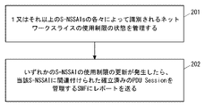
- FIG. 2 shows an example of the operation of AMF2.
- AMF2 manages the state of network slice restriction (NSR). Specifically, AMF2 manages whether there are restrictions on the use of network slices identified by each of one or more S-NSSAIs. Restrictions on the use of network slices include restrictions on the radio frequencies (e.g., frequency bands or subbands) that can use network slices, restrictions on wireless access technology (RAT) that can use network slices, and geography that can use network slices. It may include at least one of area restrictions, application restrictions that can use network slices, and priorities among multiple network slices.
- radio frequencies e.g., frequency bands or subbands
- RAT wireless access technology
- AMF2 is that an S-NSSAI is in an NSR state where it can only be used in one or more specific frequency bands, or it cannot be used in one or more specific frequency bands. You may recognize that you are in the NSR state.
- AMF2 is that an S-NSSAI is in an NSR state where it can only be used with one or more specific RATs, or it is in an NSR state where it cannot be used with one or more specific RATs. , May be recognized.
- AMF2 is that an S-NSSAI is in an NSR state where it can only be used in one or more geographic areas, or it cannot be used in one or more geographic areas. You may recognize that you are in the NSR state. Each geographic area may be a tracking area or a cell.
- AMF2 is that an S-NSSAI is in an NSR state where it is only available for a particular one or more application (or service), or it is a particular one or more. You may recognize that you are in an NSR state that is not available for your application (or service).
- AMF2 may recognize that multiple S-NSSAIs are in an NSR state where they have priority among multiple network slices (S-NSSAIs). For example, AMF2 may recognize that when a higher priority network slice is used by UE1, lower priority network slices cannot be used simultaneously by the same UE1. Alternatively, AMF2 may recognize that one S-NSSAI (network slice) is in an NSR state that cannot be used at the same time as another S-NSSAI (s) (network slice).
- AMF2 sends a report indicating the NSR status update to SMF3 when the restriction update for the use of a specific S-NSSAI occurs in UE1 (that is, the NSR status update of UE1).
- AMF2 may send the report to SMF3, which manages the established PDU Session of UE1 associated with the S-NSSAI.
- the report allows SMF3 to control the release or modification of established PDU Sessions associated with the S-NSSAI in response to NSR state updates.
- the report showing the update of the NSR status in step 202 may show the S-NSSAI and the NSR status for the S-NSSAI.
- the report may indicate that the NSR state is active, inactive, or unknown.
- the active state means that the use of the corresponding S-NSSAI is restricted.
- the inactive state means that the use of the corresponding S-NSSAI is not restricted.
- the unaware state means that it is not known whether or not the corresponding S-NSSAI is restricted.
- the report showing the update of the NSR status in step 202 may be provided to SMF3 via the Application Program Interface (API) of the event notification service (i.e., Namf_EventExposureService) provided by AMF2.
- SMF3 as an NF Service Consumer creates a new subscription when a subscription is needed to monitor at least one event related to the NSR state of at least one S-NSSAI. Request AMF2 to do so.
- the SMF3 includes an identifier that identifies a particular UE (or UE group) and a list of subscribed events (a list of e.g., S-NSSAI (s)) in the request to indicate the Subscription Target. If the request is accepted, AMF2 notifies SMF3 of the generation of event subscription. After that, when the event of the subscribed NSR status notification occurs, AMF2 sends the notification to SMF3.
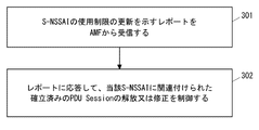
- FIG. 3 shows an example of the operation of SMF3.
- SMF3 receives a report from AMF2 indicating restrictions on the use of a particular S-NSSAI by UE1 (ie, updating the NSR state of UE1).
- SMF3 controls the release or modification of the established PDU Session of UE1 associated with the S-NSSAI in response to the report. For example, SMF3 may initiate the release of an established PDU Session or the deactivation of user plane resources for an established PDU Session if the report indicates that UE1 has restrictions on the use of network slices. SMF3 may also reject the modification of the established PDU session requested by UE1 if the report indicates that UE1 has restrictions on the use of network slices.
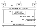
- FIG. 4 shows an example of the release procedure of the PDU Session started by SMF3.
- UE1 establishes a PDU Session.
- Step 401 may be performed according to an existing PDU session establishment procedure.
- AMF2 detects an update of UE1's NSR state for at least one S-NSSAI.
- AMF2 may detect that UE1 has moved from a geographic area where network slices are available to a geographic area where the use of network slices is restricted.
- the geographical area is a collection of Tracking Area Identity (TAI) (List of TAI), a collection of E-UTRAN Cell Global Identification (ECGI) (List of ECGI), or NR Cell Global Identity (NCGI).
- TAI Tracking Area Identity
- ECGI E-UTRAN Cell Global Identification
- NCGI NR Cell Global Identity
- the geographical area may be an Allowed Area, Non-Allowed Area, Forbidden Area, or Mobility Pattern defined in Non-Patent Document 2.
- AMF2 sends a report indicating the update of NSR status to SMF3.
- the report shows restrictions on the use of certain S-NSSAI by UE1 (ie, updating the NSR state of UE1).
- SMF3 decides to release UE1's established PDU Session for that S-NSSAI. do. More specifically, in step 404, the S-NSSAI associated with the established PDU Session is included in the report showing the update of the NSR state, and the NSR state limits its use because of the S-NSSAI. If SMF3 determines to release the established PDU Session, SMF3 determines to release the established PDU Session associated with the S-NSSAI.
- step 405 SMF3 starts the PDU Session release procedure.
- SMF3 sends a PDU SessionReleaseCommand message to UE1 via AMF2.
- the PDU SessionReleaseCommand message may include a new 5GSM cause value indicating that the use of S-NSSAI is restricted.
- the procedure of FIG. 4 may be modified as follows.
- step 404 if the report showing the NSR state update shows that UE1 has restrictions on the use of a particular S-NSSAI, then SMF3 is the user plane of UE1's established PDU Session for that S-NSSAI. You may decide to deactivate the resource.
- step 405 SMF3 may signal UPF6 to deactivate the user plane resource for the PDU Session.
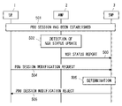
- FIG. 5 shows an example of the PDU Session Modification procedure.
- Steps 501 to 503 are the same as steps 401 to 403 in FIG.
- SMF3 receives a PPDU Session Modification Request message from UE1.
- the PDU Session Modification Request message requests modification of the PDU Session for a specific S-NSSAI.
- SMF3 determines that UE1 is restricted from using the S-NSSAI based on the report in step 503.
- SMF3 sends a PDU SessionModificationReject message to UE1.
- the PDU Session Modification Reject message may include a new 5GSM cause value indicating that the use of S-NSSAI is restricted. More specifically, in step 506, the S-NSSAI associated with the established PDUSession targeted by the PDUSessionModificationRequest message is included in the report indicating the update of the NSR state, and for the S-NSSAI. If the NSR state indicates that the use is restricted and SMF3 determines that the PDU Session Modification Request is rejected, SMF 3 sends a PDU Session Modification Reject message to UE1.
- AMF2 notifies SMF3 of the state of restriction on the use of a specific network slice by UE1. Then, SMF3 controls the release or modification of the established PDU Session of UE1 for the network slice in response to the notification from AMF2. This contributes to the realization of session management that adapts to the restrictions on the use of network slices.
- FIG. 6 shows an example of the release procedure of the PDU Session triggered by AMF2.
- the UE 1 establishes a PDU Session.
- Step 601 may be performed according to an existing PDU session establishment procedure.
- AMF2 detects an update of the NSR state of UE1 for at least one S-NSSAI.
- the operation of AMF2 in step 602 is similar to the corresponding operation described in the first embodiment (e.g., step 201 in FIG. 2, step 402 in FIG. 4).
- AMF2 detects that UE1 has restrictions on the use of a particular network slice (specific S-NSSAI).
- AMF2 requests SMF3 to release the established PDU Session of UE1 for that particular network slice.
- the request (or trigger) may include a Cause information element set to a new value (e.g., REL_DUE_TO_SLICE_NWRESTRICTION) to indicate to SMF3 that this is based on network rice usage restrictions.
- the SMF3 initiates the PDU Session Release procedure in response to the request (or trigger) of step 603.
- SMF3 sends a PDU SessionReleaseCommand message to UE1 via AMF2.
- the PDU SessionReleaseCommand message may include a new 5GSM cause value indicating that the use of S-NSSAI is restricted.
- step 604 SMF3 may initiate deactivation of the user plane resource of UE1's established PDU Session for the S-NSSAI. SMF3 may signal UPF6 to deactivate the user plane resource of the PDU Session.
- AMF2 releases the established PDU Session of UE1 for the network slice to SMF3. Request. This contributes to the realization of session management that adapts to the restrictions on the use of network slices.
- a NAS message ie, UL NAS Transport
- an SM message ie, PDU Session Establishment Request
- PDU Session Establishment Request requesting the establishment of a PDU Session associated with S-NSSAI that is not permitted to be used by UE1.
- FIG. 7 shows an example of signaling between UE1 and AMF2.
- FIG. 8 shows an example of the operation of AMF2.
- UE1 transmits a ULNAS Transport message including an N1 SM container (PDU Session Establishment Request) to AMF2 via AN5.
- AMF2 receives a ULNAS Transport message including a PDU SessionEstablishmentRequest message from UE1 (step 801).
- AMF2 manages whether there are restrictions on the use of network slices identified by each of one or more S-NSSAIs.
- Restrictions on the use of network slices include restrictions on the radio frequencies (e.g., frequency bands or subbands) that can use network slices, restrictions on wireless access technology (RAT) that can use network slices, and geography that can use network slices. It may include at least one of area restrictions, application restrictions that can use network slices, and priorities among multiple network slices.
- radio frequencies e.g., frequency bands or subbands
- RAT wireless access technology
- AMF2 is that an S-NSSAI is in an NSR state where it can only be used in one or more specific frequency bands, or it cannot be used in one or more specific frequency bands. You may recognize that you are in the NSR state.
- AMF2 is that an S-NSSAI is in an NSR state where it can only be used with one or more specific RATs, or it is in an NSR state where it cannot be used with one or more specific RATs. , May be recognized.
- AMF2 is that an S-NSSAI is in an NSR state where it can only be used in one or more geographic areas, or it cannot be used in one or more geographic areas. You may recognize that you are in the NSR state. Each geographic area may be a tracking area or a cell.
- AMF2 is that an S-NSSAI is in an NSR state where it is only available for a particular one or more application (or service), or it is a particular one or more. You may recognize that you are in an NSR state that is not available for your application (or service).
- AMF2 may recognize that multiple S-NSSAIs are in an NSR state where they have priority among multiple network slices (S-NSSAIs). For example, AMF2 may recognize that when a higher priority network slice is used by UE1, lower priority network slices cannot be used simultaneously by the same UE1. Alternatively, AMF2 may recognize that one S-NSSAI (network slice) is in an NSR state that cannot be used at the same time as another S-NSSAI (s) (network slice).
- AMF2 determines whether or not usage restrictions are imposed on the S-NSSAI associated with the PDU Session requested by UE1. In steps 703 and 803, if the S-NSSAI is subject to usage restrictions, AMF2 stops forwarding the PDU Session Establishment Request message to SMF 3 and rejects the UL NAS Transport message. As shown in step 703, AMF2 may send a DLNAS Transport message to UE1.
- the DL NAS Transport message may include a rejected N1 SM container (PDU Session Establishment Request).
- the DL NAS Transport message may include a message identifier, a message sequence number, or other identifier of the UL NAS Transport message in order to indicate the association with the rejected UL NAS Transport message.
- the DL NAS Transport message may indicate an existing 5GMM Cause value (e.g., 5GMM cause # 90 "payload was not forwarded"). Instead, the DLNAS Transport message may include a new 5GMM cause value indicating that SM messages are not forwarded due to slice usage restrictions.
- FIG. 9 shows an example of the operation of AMF2 and provides a modification of the operation shown in FIG.
- Step 901 is the same as step 801 of FIG.
- AMF2 receives a ULNAS Transport message including a PDU SessionEstablishmentRequest message from UE1.
- UE1 indicates support for network rice restriction (NSR).
- AMF2 may determine whether the received PDU Session Establishment Request message contains an indication of NSR support.
- AMF2 may determine if UE1 has indicated support for NSR during past registration procedures. More specifically, AMF2 may determine whether the context of UE1 stored in AMF2 indicates support for NSR.
- the display of NSR support may be UE1 capability information.
- Step 903 is the same as step 802 in FIG. AMF2 determines whether or not usage restrictions are imposed on the S-NSSAI associated with the PDU Session requested by UE1.
- the order of steps 902 and 903 is not limited to the order shown in FIG.
- the determination in step 902 may be performed after the determination in step 903, or may be performed at the same time as the determination in step 903.
- step 904 if UE1 does not indicate NSR support and the S-NSSAI is subject to usage restrictions, AMF2 stops forwarding the PDU Session Establishment Request message to SMF3 and the ULNAS Transport message. Reject.
- the AMF2 can reject the PDU Session establishment request regarding the slice with the usage restriction received from the UE (e.g. pre-Release 18 UE) that does not support NSR.
- the UE e.g. pre-Release 18 UE
- FIG. 10 shows an example of the operation of AMF2 and provides a modification of the operation shown in FIG.
- Step 901 is the same as step 801 of FIG.
- AMF2 receives a ULNAS Transport message including a PDU SessionEstablishmentRequest message from UE1.
- AMF2 determines whether or not usage restrictions need to be imposed on the S-NSSAI associated with the PDU Session requested by UE1.
- step 903 if the S-NSSAI needs to be restricted, AMF2 stops forwarding the PDU SessionEstablishmentRequest message to SMF3 and rejects the ULNAS Transport message.
- the AMF2 when the AMF2 receives the PDU Session Establishment Request and the network slice usage restriction is enabled at the same time, the AMF2 promptly requests the PDU Session establishment for the network slice to which the usage restriction needs to be imposed. Can be rejected.
- FIG. 11 shows a modification of the signaling shown in FIG. 7.
- AMF2 may receive information about NSR from other network functions (Network Function (NF)) 1100.
- the NF1100 may be the NSSF4, UDM8, or UDR described above.
- the NF1100 may be any other of the 5GC's existing NFs, for example PolicyControlFunction (PCF) or NetworkDataAnalyticsFunction (NWDAF).
- PCF PolicyControlFunction
- NWDAF NetworkDataAnalyticsFunction
- the NF1100 may be a new network function of 5GC.
- AMF2 queries NF1100 for information about the NSR.
- AMF2 receives a report (e.g., NSR report) containing information about NSR from NF1100.
- a report e.g., NSR report
- AMF control the forwarding of SM messages (PDU Session Establishment Request messages) to SMF in consideration of restrictions on the use of network slices.
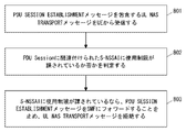
- FIG. 12 shows an example of signaling between UE1, AMF2, and SMF3.
- FIG. 13 shows an example of the operation of AMF2.
- Step 1201 is the same as step 701 in FIG.
- UE1 transmits a ULNAS Transport message including an N1 SM container (PDU Session Establishment Request) to AMF2 via AN5.
- AMF2 receives a ULNAS Transport message including a PDU SessionEstablishmentRequest message from UE1 (step 1301).
- AMF2 manages whether there are restrictions on the use of network slices identified by each of one or more S-NSSAIs.
- Restrictions on the use of network slices include restrictions on the radio frequencies (e.g., frequency bands or subbands) that can use network slices, restrictions on wireless access technology (RAT) that can use network slices, and geography that can use network slices. It may include at least one of area restrictions, application restrictions that can use network slices, and priorities among multiple network slices.
- radio frequencies e.g., frequency bands or subbands
- RAT wireless access technology
- AMF2 is that an S-NSSAI is in an NSR state where it can only be used in one or more specific frequency bands, or it cannot be used in one or more specific frequency bands. You may recognize that you are in the NSR state.
- AMF2 is that an S-NSSAI is in an NSR state where it can only be used with one or more specific RATs, or it is in an NSR state where it cannot be used with one or more specific RATs. , May be recognized.
- AMF2 is that an S-NSSAI is in an NSR state where it can only be used in one or more geographic areas, or it cannot be used in one or more geographic areas. You may recognize that you are in the NSR state. Each geographic area may be a tracking area or a cell.
- AMF2 is that an S-NSSAI is in an NSR state where it is only available for a particular one or more application (or service), or it is a particular one or more. You may recognize that you are in an NSR state that is not available for your application (or service).
- AMF2 may recognize that multiple S-NSSAIs are in an NSR state where they have priority among multiple network slices (S-NSSAIs). For example, AMF2 may recognize that when a higher priority network slice is used by UE1, lower priority network slices cannot be used simultaneously by the same UE1. Alternatively, AMF2 may recognize that one S-NSSAI (network slice) is in an NSR state that cannot be used at the same time as another S-NSSAI (network slice). Similar to the operation shown in FIG. 11, the AMF2 may receive information about the NSR from other network functions.
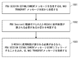
- AMF2 determines whether or not usage restrictions need to be imposed (or whether or not) are imposed on the S-NSSAI associated with the PDU Session requested by UE1. In steps 1203 and 1303, if the S-NSSAI needs (or is) restricted in use, AMF2 states that the establishment of the PDU Session should be rejected because of the restricted use. Forward the PDU Session Establishment message to SMF3 with the indication. Specifically, the AMF2 sends a control message (e.g., Nsmf_PDUSession_CreateSMContextRequest) including the PDUSessionEstablishment message and the display to the SMF3.
- the display may be, for example, "REJECT_DUE_TO_SLICE_NWRESTRICTION".
- the SMF3 rejects the establishment of the PDU Session if it receives the PDU Session Establishmentment message with an indication that the establishment of the PDU Session should be rejected due to usage restrictions.
- the SMF3 sends a PDU SessionEstablishmentReject message to UE1 via AMF2 (steps 1204 and 1205).
- the PDU SessionEstablishmentReject message may include a new 5GSM cause value indicating a slice usage limit.
- AMF2 and SMF3 can reject the request for establishing a PDU Session regarding a network slice for which usage restrictions are imposed. This contributes to the realization of session management that adapts to the restrictions on the use of network slices.
- FIG. 14 is a block diagram showing a configuration example of UE1.
- Radio Frequency (RF) transceiver 1401 performs analog RF signal processing to communicate with RAN nodes.
- the RF transceiver 1401 may include a plurality of transceivers.
- the analog RF signal processing performed by the RF transceiver 1401 includes frequency up-conversion, frequency down-conversion, and amplification.
- the RF transceiver 1401 is coupled with the antenna array 1402 and the baseband processor 1403.
- the RF transceiver 1401 receives modulation symbol data (or OFDM symbol data) from the baseband processor 1403, generates a transmit RF signal, and supplies the transmit RF signal to the antenna array 1402. Further, the RF transceiver 1401 generates a baseband reception signal based on the received RF signal received by the antenna array 1402, and supplies the baseband reception signal to the baseband processor 1403.
- the RF transceiver 1401 may include an analog beamformer circuit for beamforming.
- the analog beamformer circuit includes, for example, a plurality of phase shifters and a plurality of power amplifiers.
- the baseband processor 1403 performs digital baseband signal processing (data plane processing) and control plane processing for wireless communication.
- Digital baseband signal processing includes (a) data compression / restoration, (b) data segmentation / concatenation, (c) transmission format (transmission frame) generation / decomposition, and (d) transmission path coding / decoding. , (E) Modulation (symbol mapping) / demodulation, and (f) Generation of OFDM symbol data (baseband OFDM signal) by Inverse Fast Fourier Transform (IFFT).
- IFFT Inverse Fast Fourier Transform
- control plane processing includes layer 1 (e.g., transmission power control), layer 2 (e.g., radio resource management, and hybrid automatic repeat request (HARQ) processing), and layer 3 (e.g., attach, mobility, and call management). Includes communication management (signaling regarding).
- layer 1 e.g., transmission power control
- layer 2 e.g., radio resource management, and hybrid automatic repeat request (HARQ) processing
- layer 3 e.g., attach, mobility, and call management.
- Includes communication management (signaling regarding).
- digital baseband signal processing by the baseband processor 1403 includes a ServiceDataAdaptationProtocol (SDAP) layer, a PacketDataConvergenceProtocol (PDCP) layer, a RadioLinkControl (RLC) layer, a MediumAccessControl (MAC) layer, and a Physical. (PHY) layer signal processing may be included.
- SDAP ServiceDataAdaptationProtocol
- PDCP PacketDataConvergenceProtocol
- RLC RadioLinkControl
- MAC MediumAccessControl
- PHY Physical.
- control plane processing by the baseband processor 1403 may include the processing of the Non-Access Stratum (NAS) protocol, the Radio Resource Control (RRC) protocol, and the MAC Control Elements (CEs).
- NAS Non-Access Stratum
- RRC Radio Resource Control
- CEs MAC Control Elements
- the baseband processor 1403 may perform Multiple Input Multiple Output (MIMO) encoding and precoding for beamforming.
- MIMO Multiple Input Multiple Output
- the baseband processor 1403 includes a modem processor (e.g., Digital Signal Processor (DSP)) that performs digital baseband signal processing and a protocol stack processor (e.g., Central Processing Unit (CPU) or Micro Processing Unit (e.g., Central Processing Unit (CPU)) that performs control plane processing. MPU)) may be included.
- DSP Digital Signal Processor
- MPU Central Processing Unit
- the protocol stack processor that performs the control plane processing may be shared with the application processor 1404 described later.
- the application processor 1404 is also called a CPU, MPU, microprocessor, or processor core.
- the application processor 1404 may include a plurality of processors (a plurality of processor cores).
- the application processor 1404 is a system software program (Operating System (OS)) read from memory 1406 or a memory (not shown) and various application programs (eg, call application, web browser, mailer, camera operation application, music playback). By executing the application), various functions of UE1 are realized.
- OS Operating System
- the baseband processor 1403 and application processor 1404 may be integrated on one chip, as shown by the dashed line (1405) in FIG.
- the baseband processor 1403 and the application processor 1404 may be implemented as one System on Chip (SoC) device 1405.
- SoC devices are sometimes referred to as system Large Scale Integration (LSI) or chipsets.
- Memory 1406 is a volatile memory, a non-volatile memory, or a combination thereof.
- the memory 1406 may include a plurality of physically independent memory devices.
- the volatile memory is, for example, Static Random Access Memory (SRAM), Dynamic RAM (DRAM), or a combination thereof.
- the non-volatile memory is a mask ReadOnlyMemory (MROM), Electrically ErasableProgrammableROM (EEPROM), flash memory, or hard disk drive, or any combination thereof.
- the memory 1406 may include an external memory device accessible from the baseband processor 1403, the application processor 1404, and the SoC 1405.
- the memory 1406 may include an internal memory device integrated in the baseband processor 1403, in the application processor 1404, or in the SoC 1405. Further, the memory 1406 may include the memory in the Universal Integrated Circuit Card (UICC).
- UICC Universal Integrated Circuit Card
- the memory 1406 may store one or more software modules (computer programs) 1407 including instruction groups and data for performing processing by the UE 1 described in the plurality of embodiments described above.
- the baseband processor 1403 or application processor 1404 is configured to read the software module 1407 from the memory 1406 and execute it to perform the processing of UE1 described with reference to the drawings in the above embodiments. May be done.
- control plane processing and operation performed by UE1 described in the above-described embodiment is performed by at least one of the other elements except the RF transceiver 1401 and the antenna array 1402, that is, the baseband processor 1403 and the application processor 1404, and the software module 1407. It can be realized by the memory 1406 that stores the above.
- FIG. 15 shows a configuration example of AMF2.
- SMF3 may also have the configuration shown in FIG.
- AMF2 includes a network interface 1501, a processor 1502, and a memory 1503.
- the network interface 1501 is used, for example, to communicate with (R) AN nodes and to communicate with other network functions (NFs) or nodes within 5GC.
- Other NFs or nodes within the 5GC include, for example, UDM, AUSF, SMF, and PCF.
- the network interface 1501 may include, for example, a network interface card (NIC) compliant with the IEEE802.3 series.
- NIC network interface card
- the processor 1502 may be, for example, a microprocessor, a MicroProcessingUnit (MPU), or a CentralProcessingUnit (CPU). Processor 1502 may include a plurality of processors.
- MPU MicroProcessingUnit
- CPU CentralProcessingUnit
- the memory 1503 is composed of a volatile memory and a non-volatile memory.
- the memory 1503 may include a plurality of physically independent memory devices.
- the volatile memory is, for example, Static Random Access Memory (SRAM), Dynamic RAM (DRAM), or a combination thereof.
- the non-volatile memory is a mask ReadOnlyMemory (MROM), Electrically ErasableProgrammableROM (EEPROM), flash memory, or hard disk drive, or any combination thereof.
- the memory 1503 may include storage located away from the processor 1502. In this case, the processor 1502 may access the memory 1503 via the network interface 1501 or the I / O interface.
- the memory 1503 may store at least one software module (computer program) 1504 including the instruction group and data for performing the processing by the AMF2 described in the plurality of embodiments described above.
- the processor 1502 may be configured to read the software module 1504 from the memory 1503 and execute it to perform the processing of AMF2 described in the above embodiment.
- each of the processors included in UE1, AMF2, and SMF3 provides instructions for causing the computer to perform the algorithm described with reference to the drawings.
- This program is stored using various types of non-transitory computer readable medium and can be supplied to a computer.
- Non-temporary computer-readable media include various types of tangible storage mediums.
- non-temporary computer readable media are magnetic recording media (eg flexible disks, magnetic tapes, hard disk drives), magneto-optical recording media (eg magneto-optical disks), CompactDiscReadOnlyMemory (CD-ROM), CD- Includes R, CD-R / W, semiconductor memory (eg, mask ROM, Programmable ROM (PROM), Erasable PROM (EPROM), flash ROM, Random Access Memory (RAM)).
- the program may also be supplied to the computer by various types of transient computer readable medium.
- Examples of temporary computer readable media include electrical, optical, and electromagnetic waves.
- the temporary computer-readable medium can supply the program to the computer via a wired communication path such as an electric wire and an optical fiber, or a wireless communication path.
- (Appendix A1) A core network node for mobility management With at least one memory With at least one processor coupled to the at least one memory, Equipped with The at least one processor releases the established PDU Session associated with the network slice or deactivates the user plane resource of the established PDU Session in response to an update of the restriction on the use of the network slice. Configured to request core network nodes for session management, Core network node for mobility management. (Appendix A2)
- the restrictions include limits on the radio frequencies that can use the network slices, limits on the radio access technology that can use the network slices, limits on the geographic areas where the network slices can be used, and applications where the network slices can be used. Includes at least one of the limits of, and the priority-based limits between multiple network slices.
- the core network node for mobility management according to the appendix A1.
- Appendix A3 A method performed by core network nodes for mobility management, Releasing the established PDU Session associated with the network slice or deactivating the user plane resource of the established PDU Session in response to an update of the restriction on the use of the network slice, the core network node for session management. Be prepared to request Method.
- Appendix B1 A core network node for mobility management With at least one memory With at least one processor coupled to the at least one memory, Equipped with The at least one processor A first Non-Access Stratum (NAS) message containing a Session Management (SM) message requesting the establishment of a PDU Session is received from the User Equipment (UE).
- NAS Non-Access Stratum
- SM Session Management
- the usage restrictions include restrictions on the radio frequencies that can use network slices, restrictions on wireless access technologies that can use network slices, restrictions on geographic areas that can use network slices, and restrictions on applications that can use network slices. And a priority-based limit between multiple network slices, including at least one. Core network node for mobility management.
- the at least one processor sends the SM message to the core network node for session management if the UE does not indicate support for network slice restrictions and the network slice identifier is subject to the usage restrictions. Stop forwarding and reject the NAS message, The core network node for mobility management described in Appendix B1.
- the at least one processor is configured to send a second NAS message to the UE, including a cause value indicating that the SM message is not forwarded due to the usage restrictions.
- the at least one processor is configured to receive information indicating the usage restriction from other network functions.
- Appendix B5 A method performed by core network nodes for mobility management, Receiving a first Non-Access Stratum (NAS) message from the User Equipment (UE) that includes a Session Management (SM) message requesting the establishment of a PDU Session. Determining if the network slice identifier associated with the PDU Session is or should be restricted, and whether the network slice identifier is subject to or should be restricted. Stop forwarding the SM message to the core network node for session management and reject the NAS message if it needs to be imposed. Equipped with The usage restrictions include restrictions on the radio frequencies that can use network slices, restrictions on wireless access technologies that can use network slices, restrictions on geographic areas that can use network slices, and restrictions on applications that can use network slices.
- NAS Non-Access Stratum
- UE User Equipment
- SM Session Management
- Method. A program for causing a computer to perform a method for a core network node for mobility management, wherein the method is Receiving a first Non-Access Stratum (NAS) message from the User Equipment (UE) that includes a Session Management (SM) message requesting the establishment of a PDU Session. Determining if the network slice identifier associated with the PDU Session is or should be restricted, and whether the network slice identifier is subject to or is subject to such restrictions. Stop forwarding the SM message to the core network node for session management and reject the NAS message if it needs to be imposed.
- NAS Non-Access Stratum
- UE User Equipment
- SM Session Management
- the usage restrictions include restrictions on the radio frequencies that can use network slices, restrictions on wireless access technologies that can use network slices, restrictions on geographic areas that can use network slices, and restrictions on applications that can use network slices. And a priority-based limit between multiple network slices, including at least one. program.
- Appendix C1 A core network node for mobility management With at least one memory With at least one processor coupled to the at least one memory, Equipped with The at least one processor Receive a Non-Access Stratum (NAS) message from the User Equipment (UE) that contains a Session Management (SM) message requesting the establishment of a PDU Session. Determine if the network slice identifier associated with the PDU Session is or should be restricted.
- NAS Non-Access Stratum
- UE User Equipment
- SM Session Management
- the usage restrictions include restrictions on the radio frequencies that can use network slices, restrictions on wireless access technologies that can use network slices, restrictions on geographic areas that can use network slices, and restrictions on applications that can use network slices. And a priority-based limit between multiple network slices, including at least one.
- Core network node for mobility management. (Appendix C2)
- the at least one processor is configured to receive information indicating the usage restriction from other network functions.
- a control message containing a first Session Management (SM) message requesting the establishment of a PDU Session for User Equipment (UE) is received from the core network node for mobility management. If the control message contains an indication that the establishment of the PDU Session should be rejected due to usage restrictions, the establishment of the PDU Session is rejected.
- the usage restrictions include restrictions on the radio frequencies that can use network slices, restrictions on wireless access technologies that can use network slices, restrictions on geographic areas that can use network slices, and restrictions on applications that can use network slices. And a priority-based limit between multiple network slices, including at least one.
- Core network node for session management The at least one processor sends a second SM message containing a cause value indicating that the establishment of the PDU Session is rejected due to the usage restriction to the UE via the core network node for mobility management.
- Appendix C5 A method performed by core network nodes for mobility management, Receiving a Non-Access Stratum (NAS) message from User Equipment (UE), including a Session Management (SM) message requesting the establishment of a PDU Session, Determining if the network slice identifier associated with the PDU Session is or should be restricted, and whether the network slice identifier is subject to or should be restricted.
- NAS Non-Access Stratum
- UE User Equipment
- SM Session Management
- Method. It is a method performed by the core network node for session management. Receiving a control message from a core network node for mobility management, including a first Session Management (SM) message requesting the establishment of a PDU Session for User Equipment (UE), and the establishment of the PDU Session used.
- SM Session Management
- the usage restrictions include restrictions on the radio frequencies that can use network slices, restrictions on wireless access technologies that can use network slices, restrictions on geographic areas that can use network slices, and restrictions on applications that can use network slices. And a priority-based limit between multiple network slices, including at least one. Method.
- the at least one processor is configured to reject the modification of the established PDU session requested by the UE if the report indicates that the use of the network slice is limited.
- the core network node for session management according to Appendix 1 or 2.
- the report contains information indicating whether the restrictions on the use of the network slices are activated, deactivated or unknown.
- the at least one processor is configured to control the release or modification of the established PDU Session associated with the network slice when the information indicates that the restriction has been activated.
- the core network node for session management according to any one of Supplementary note 1 to 3.
- the at least one processor A request to join the notification service regarding restrictions on the use of the network slice by the UE is transmitted to the core network node for mobility management.
- a core network node for mobility management With at least one memory With at least one processor coupled to the at least one memory, Equipped with The at least one processor is configured to send a report indicating that the limit update has occurred to the core network node for session management in response to the user equipment (UE) updating the limit for the use of the network slice. Be done, Core network node for mobility management.
- the restrictions include limits on the radio frequencies that can use the network slices, limits on the radio access technology that can use the network slices, limits on the geographic areas where the network slices can be used, and applications where the network slices can be used.
- the core network node for mobility management includes at least one of the limits of, and the priority-based limits between multiple network slices.
- the core network node for mobility management according to Appendix 6. The report contains information indicating whether the restriction on the use of the network slice is activated, deactivated or unknown.
- the core network node for mobility management according to Appendix 6 or 7. The at least one processor
- a request to join the notification service regarding the restriction on the use of the network slice by the UE is received from the core network node for session management. It is configured to send a report corresponding to the request to the core network node for session management.
- the core network node for mobility management according to any one of Supplementary note 6 to 8. (Appendix 10) It is a method performed by the core network node for session management.
- a method performed by core network nodes for mobility management In response to a limit update for the use of network slices by the User Equipment (UE), it comprises sending a report to the core network node for session management that the limit update has occurred.
- (Appendix 12) A program that causes a computer to perform a method for a core network node for session management, wherein the method is Receiving a report from the core network node for mobility management indicating that a restriction update for the use of the network slice by the User Equipment (UE) has occurred, and being associated with the network slice in response to receiving the report. Controlling the release or modification of the established PDU Session of the UE, The program.
- (Appendix 13) A program that lets computers do the methods for core network nodes for mobility management. The method comprises sending a report indicating that the limit update has occurred to the core network node for session management in response to the limit update for the use of the network slice by the User Equipment (UE). program.
Landscapes
- Engineering & Computer Science (AREA)
- Computer Networks & Wireless Communication (AREA)
- Signal Processing (AREA)
- Computer Security & Cryptography (AREA)
- Mobile Radio Communication Systems (AREA)
Abstract
A core network node (3) for session management that receives, from a core network node (2) for mobility management, a report indicating that resitrictions on the use of a network slice by UE (1) have been updated. In response to receiving the report, the core network node (3) for session management controls the analysis or correction of an established PDU Session for the UE (1) that is associated with the network slice. This, for example, can contribute to the achievement of session management that is adapted to restrictions on the use of a network slice.
Description
本開示は、無線通信ネットワークに関し、特にnetwork slicingに関する。
This disclosure relates to wireless communication networks, especially network slicing.
5G system(5GS)は、network slicingをサポートする。Network slicingは、複数の論理的なネットワーク又は仮想化されていない論理的なネットワークを物理的なネットワークの上に作り出すことを可能にする。例えば、Network slicingは、Network Function Virtualization(NFV)技術及びsoftware-defined networking(SDN)技術を使用し、これにより複数の仮想化された論理的なネットワークを物理的なネットワークの上に作り出してもよい。各々の論理的なネットワークは、ネットワークスライス(network slice)と呼ばれる。ネットワークスライスは、特定のネットワーク能力及びネットワーク特性(specific network capabilities and network characteristics)を提供する。ネットワークスライス・インスタンス(network slice instance(NSI))は、1つのネットワークスライスを形成するために、ネットワーク機能(Network Function(NF))インスタンスと、リソース(resources)(e.g., computer processing resources、storage、及びnetworking resources)と、アクセスネットワーク(AN)(Next Generation Radio Access Network(NG-RAN)及びNon-3GPP InterWorking Function (N3IWF)の一方又は両方)と、のセットとして定義される。
5G system (5GS) supports network slicing. Network slicing makes it possible to create multiple logical networks or unvirtualized logical networks on top of physical networks. For example, Network slicing may use Network Function Virtualization (NFV) technology and software-defined networking (SDN) technology to create multiple virtualized logical networks on top of a physical network. .. Each logical network is called a network slice. Network slices provide specific network capabilities and network characteristics. A network slice instance (NSI) is a network function (NF) instance and resources (e.g., computer processing resources, storage, and storage) to form a single network slice. Networking resources) and one or both of the access network (AN) (Next Generation Radio Access Network (NG-RAN) and Non-3GPP InterWorking Function (N3IWF)).
ネットワークスライスは、Single Network Slice Selection Assistance Information(S-NSSAI)として知られる識別子によって特定される。S-NSSAIは、Slice/Service type (SST)及びSlice Differentiator (SD)から成る。SSTは、特性及びサービス(features and services)に関して期待されるネットワークスライスの振る舞い(expected network slice behavior)を意味する(refers to)。SDは、任意の情報(optional information)であり、同じSlice/Service typeの複数(multiple)ネットワークスライスを区別するためにSSTを補完(complements)する。
The network slice is identified by an identifier known as Single Network Slice Selection Assistance Information (S-NSSAI). S-NSSAI consists of Slice / Service type (SST) and Slice Differentiator (SD). SST means referreds to expected network slice behavior with respect to features and services. SD is optional information and complements SST to distinguish between multiple network slices of the same Slice / Service type.
S-NSSAIは、標準値(standard values)又は非標準値(non-standard values)を持つことができる。現時点では、Standard SST valuesの1、2、3、及び4は、enhanced Mobile Broad Band (eMBB)、Ultra Reliable and Low Latency Communication (URLLC)、Massive Internet of Things (MIoT)、及びVehicle to Everything (V2X)スライスタイプ(slice types)に関連付けられている。S-NSSAIのnon-standard valueは、特定のPublic Land Mobile Network(PLMN)内の1つのネットワークスライスを特定する。すなわち、non-standard SST valuesは、PLMN-specific valuesであり、これらをアサインしたPLMNのPLMN IDに関連付けられる。各S-NSSAIは、特定の(particular)NSIを選択する点でネットワークの独立性(isolation)を保証する。同じNSIは、異なるS-NSSAIsを介して選択されてもよい。同じS-NSSAIは、異なるNSIに関連付けられてもよい。各ネットワークスライスはS-NSSAIによってユニークに特定されてもよい。
S-NSSAI can have standard values or non-standard values. At the moment, Standard SST values 1, 2, 3, and 4 are enhanced Mobile Broad Band (eMBB), Ultra Reliable and Low Latency Communication (URLLC), Massive Internet of Things (MIoT), and Vehicle to Everything (V2X). It is associated with slice types. The non-standard value of S-NSSAI identifies one network slice within a particular Public Land Mobile Network (PLMN). That is, non-standard SST values are PLMN-specific values and are associated with the PLMN ID of the PLMN to which they are assigned. Each S-NSSAI guarantees network independence in choosing a particular NSI. The same NSI may be selected via different S-NSSAIs. The same S-NSSAI may be associated with different NSIs. Each network slice may be uniquely identified by S-NSSAI.
S-NSSAIには二つの種類があり、これらはS-NSSAI及びMapped S-NSSAIとして知られている。S-NSSAIは、UEが接続するserving Public Land Mobile Network(PLMN)が提供するネットワークスライスを識別する。従って、ホーム網在圏時は、S-NSSAIはホーム網(e.g., Home PLMN(HPLMN))のネットワークスライスを識別する。ローミング時、S-NSSAIは、ローミング網(e.g., Visited PLMN(VPLMN))のネットワークスライスを識別する。Mapped S-NSSAIは、UEがローミングしている際に、ローミング網のネットワークスライスを識別するS-NSSAIにマッピングされる(関連付けられる、または該当する)Home PLMN(HPLMN)のS-NSSAIであってもよく、さらにその中でUEユーザーの加入者情報に含まれるS-NSSAIであってもよい。
There are two types of S-NSSAI, which are known as S-NSSAI and Mapped S-NSSAI. S-NSSAI identifies the network slice provided by the serving Public Land Mobile Network (PLMN) to which the UE connects. Therefore, when the home network is in the area, S-NSSAI identifies the network slice of the home network (e.g., Home PLMN (HPLMN)). When roaming, S-NSSAI identifies the network slice of the roaming network (e.g., Visited PLMN (VPLMN)). Mapped S-NSSAI is a Home PLMN (HPLMN) S-NSSAI that is mapped (associated or applicable) to the S-NSSAI that identifies the network slice of the roaming network when the UE is roaming. It may be S-NSSAI included in the subscriber information of the UE user.
一方、Network Slice Selection Assistance Information(NSSAI)は、S-NSSAIsのセットを意味する。したがって、少なくとも1つのS-NSSAIが1つのNSSAIに含まれることができる。NSSAIには複数のタイプがあり、これらはConfigured NSSAI、Requested NSSAI、Allowed NSSAI、Rejected NSSAI、及びPending NSSAIとして知られている。
On the other hand, Network Slice Selection Assistance Information (NSSAI) means a set of S-NSSAIs. Therefore, at least one S-NSSAI can be included in one NSSAI. There are multiple types of NSSAI, known as Configured NSSAI, Requested NSSAI, Allowed NSSAI, Rejected NSSAI, and Pending NSSAI.
Configured NSSAIは、各々が少なくとも1つのPLMNに適用可能(applicable)な少なくとも1つのS-NSSAIを含む。Configured NSSAIは、例えば、Serving PLMNによって設定され、当該Serving PLMNに適用される。あるいは、Configured NSSAIは、Default Configured NSSAIであってもよい。Default Configured NSSAIは、Home PLMN(HPLMN)によって設定され、特定の(specific)Configured NSSAIが提供されていない任意の(any)PLMNsに適用される。Default Configured NSSAIは、例えば、HPLMNのUnified Data Management(UDM)からAccess and Mobility Management Function(AMF)を介して無線端末(User Equipment(UE))にプロビジョンされる。
Configured NSSAI includes at least one S-NSSAI, each applicable to at least one PLMN. The Configured NSSAI is set by, for example, the Serving PLMN and is applied to the Serving PLMN. Alternatively, the Configured NSSAI may be the Default Configured NSSAI. The Default Configured NSSAI is set by the Home PLMN (HPLMN) and applies to any (any) PLMNs for which no specific (specific) Configured NSSAI is provided. Default Configured NSSAI is provisioned from Unified Data Management (UDM) of HPLMN to a wireless terminal (User Equipment (UE)) via Access and Mobility Management Function (AMF), for example.
Requested NSSAIは、例えば登録手順(registration procedure)において、UEによってネットワークにシグナルされ、当該UEのためのServing AMF、少なくとも1つのネットワークスライス、及び少なくとも1つのNSIを決定することをネットワークに可能にする。
The Requested NSSAI is signaled to the network by the UE, for example, in a registration procedure, allowing the network to determine a Serving AMF, at least one network slice, and at least one NSI for that UE.
Allowed NSSAIは、Serving PLMNによってUEに提供され、当該Serving PLMNの現在の(current)Registration Area(RA)において当該UEが使用することができる少なくとも1つのS-NSSAIを示す。Allowed NSSAIは、Serving PLMNのAMFによって、例えば登録手順(registration procedure)の間に決定される。Allowed NSSAIは、ネットワーク(i.e., AMF)によってUEにシグナルされ、AMF及びUEのそれぞれのメモリ(e.g., 不揮発性(non-volatile)メモリ)に格納される。
Allowed NSSAI indicates at least one S-NSSAI provided to the UE by the Serving PLMN and can be used by the UE in the current Registration Area (RA) of the Serving PLMN. Allowed NSSAI is determined by the AMF of the Serving PLMN, for example, during the registration procedure. Allowed NSSAI is signaled to the UE by the network (i.e., AMF) and stored in the respective memories (e.g., non-volatile) of the AMF and the UE.
Rejected NSSAIは、現在の(current)PLMNによって拒絶された少なくとも1つのS-NSSAIを含む。Rejected NSSAIは、rejected S-NSSAIsと呼ばれることもある。S-NSSAIは、現在のPLMN全体で拒絶されるか、又は現在の(current)登録エリア(RA)で拒絶される。AMFは、例えばUEの登録手順(registration procedure)において、Requested NSSAIに含まれる少なくとも1つのS-NSSAIのうちいずれかを拒絶したなら、これらをRejected NSSAIに含める。Rejected NSSAIは、ネットワーク(i.e., AMF)によってUEにシグナルされ、AMF及びUEのそれぞれのメモリに格納される。
Rejected NSSAI includes at least one S-NSSAI rejected by the current (current) PLMN. Rejected NSSAI is sometimes called rejected S-NSSAIs. S-NSSAI is either rejected by the current PLMN as a whole or rejected by the current (current) registration area (RA). If the AMF rejects any one of at least one S-NSSAI included in the Requested NSSAI, for example, in the registration procedure of the UE, these are included in the Rejected NSSAI. The Rejected NSSAI is signaled to the UE by the network (i.e., AMF) and stored in the respective memories of the AMF and the UE.
Pending NSSAIは、ネットワークスライスに特化した認証及び認可(Network Slice-Specific Authentication and Authorization(NSSAA))が保留中である少なくとも1つのS-NSSAIを示す。Serving PLMNは、加入者情報(subscription information)に基づいてNSSAAを課されたHPLMNのS-NSSAI(s)に対してNSSAAを行わなければならない。NSSAAを行うために、AMFは、Extensible Authentication Protocol(EAP)-based authorization procedureを実施(invoke)する。EAP-based authentication procedureはその結果(outcome)を得るまでに比較的長い時間を要する。したがって、AMFは、UEの登録手順(registration procedure)において上述のようにAllowed NSSAIを決定するが、NSSAAを課されたS-NSSAI(s)を当該Allowed NSSAIに含めず、これらを代わりにPending NSSAIに含める。Pending NSSAIは、ネットワーク(i.e., AMF)によってUEにシグナルされ、AMF及びUEのそれぞれのメモリに格納される。
Pending NSSAI indicates at least one S-NSSAI for which authentication and authorization (Network Slice-Specific Authentication and Authorization (NSSAA)) specialized for network slices are pending. The Serving PLMN must perform NSSAA on the HPLMN's S-NSSAI (s), which is subject to NSSAA based on subscription information. In order to perform NSSAA, AMF implements Extensible Authentication Protocol (EAP) -based authorization procedure (invoke). EAP-based authentication procedure takes a relatively long time to obtain the result (outcome). Therefore, AMF determines Allowed NSSAI as described above in the registration procedure of UE, but does not include S-NSSAI (s) imposed by NSSAA in the Allowed NSSAI, and instead includes them in Pending NSSAI. Include in. Pending NSSAI is signaled to the UE by the network (i.e., AMF) and stored in the respective memories of AMF and UE.
3rd Generation Partnership Project(3GPP)は、Release 17に関してネットワークスライスの機能強化(enhancements)を検討している。さらに、3GPP Technical Specification Group Services and System Aspects (TSG-SA) Working Group 1 (WG1)は、Enhanced Access to and Support of Network Sliceの実現可能性(feasibility)を調査(investigate)するためにRelease 18のための新たなworking/study itemを承認した(非特許文献1を参照)。このstudy itemの目的(objectives)の1つは、ある周波数バンド/サブバンド、Radio Access Technologies(RATs)、地理的エリア、ネットワーク、及びアプリケーション等へのネットワークスライスの制限がある場合に、ネットワークスライスの様々な配置及び利用シナリオを特定することである(identifying various deployment and usage scenarios of network slices, when there is a restriction of network slice to e.g., certain frequency bands/sub bands, RATs, geographical areas, networks and applications)。このstudy itemの目的(objectives)の他の1つは、User Equipment(UE)が複数のネットワークスライスへのサブスクリプションを有し且つこれらのネットワークスライスが周波数バンド/サブバンド、Radio Access Technologies(RATs)、地理的エリア、ネットワーク、及びアプリケーション等のために配置されている場合に、ネットワークスライスの様々な配置及び利用シナリオを特定することである(identifying various deployment and usage scenarios of network slices, when a UE has a subscription to multiple network slices and these network slices are deployed for e.g., different frequency bands/sub bands, RATs, geographical area and applications)。
The 3rd Generation Partnership Project (3GPP) is considering enhancing network slice functions for Release 17. In addition, 3GPP Technical Specification Group Services and System Aspects (TSG-SA) Working Group 1 (WG1) is for Release 18 to investigate the feasibility of Enhanced Access to Support of Network Slice. Approved a new working / study item (see Non-Patent Document 1). One of the objectives of this study item is to limit network slices to certain frequency bands / subbands, RadioAccess Technologies (RATs), geographic areas, networks, applications, etc. Identifying various deployments and usage scenarios of network slices, when there is a restriction of network slices to e.g., ceramic frequency bands / subbands, RATs, geographical areas .. Another of the objectives of this study item is that the User Equipment (UE) has subscriptions to multiple network slices, and these network slices are frequency band / subband, RadioAccess Technologies (RATs). Identifying various deployments and usage scenarios of network slices, when a UE has, when deployed for geographic areas, networks, applications, etc. a subscription to multiple network slices and these network slices are deployed for e.g., different frequency bands / sub bands, RATs, geographical area and applications).
現時点では、ネットワークスライスの使用に対する様々な制限(e.g., 周波数バンド、地理的エリア、又はアプリケーションに関する制限)にUE及びネットワークがどのように対処するかが明確でない。例えば、ネットワークスライスの使用の制限に基づいて、コアネットワークがUEのセッション管理(session management)をどのように行うかが明確でない。
At this time, it is not clear how UE and the network will deal with various restrictions on the use of network slices (e.g., frequency band, geographic area, or application restrictions). For example, it is not clear how the core network manages the UE for sessions based on the restrictions on the use of network slices.
ここに開示される実施形態が達成しようとする目的の1つは、ネットワークスライスの使用に対する制限に適応したセッション管理の実現に寄与する装置、方法、及びプログラムを提供することである。なお、この目的は、ここに開示される複数の実施形態が達成しようとする複数の目的の1つに過ぎないことに留意されるべきである。その他の目的又は課題と新規な特徴は、本明細書の記述又は添付図面から明らかにされる。
One of the objectives to be achieved by the embodiments disclosed herein is to provide devices, methods, and programs that contribute to the realization of session management adapted to the restrictions on the use of network slices. It should be noted that this object is only one of the purposes that the plurality of embodiments disclosed herein seek to achieve. Other objectives or issues and novel features will be apparent from the description or accompanying drawings herein.
第1の態様では、セッション管理用のコアネットワークノードは、少なくとも1つのメモリと、前記少なくとも1つのメモリに結合された少なくとも1つのプロセッサとを備える。前記少なくとも1つのプロセッサは、UEによるネットワークスライスの使用に対する制限の更新が発生したことを示すレポートをモビリティ管理用のコアネットワークノードから受信するよう構成される。前記少なくとも1つのプロセッサは、さらに、前記レポートの受信に応答して、前記ネットワークスライスに関連付けられた前記UEの確立済みPDU Sessionの解放又は修正を制御するよう構成される。
In the first aspect, the core network node for session management includes at least one memory and at least one processor coupled to the at least one memory. The at least one processor is configured to receive a report from the core network node for mobility management indicating that a restriction update for the use of network slices by the UE has occurred. The at least one processor is further configured to control the release or modification of the established PDU Session of the UE associated with the network slice in response to receiving the report.
第2の態様では、モビリティ管理用のコアネットワークノードは、少なくとも1つのメモリと、前記少なくとも1つのメモリに結合された少なくとも1つのプロセッサとを備える。前記少なくとも1つのプロセッサは、UEによるネットワークスライスの使用に対する制限の更新に応答して、前記制限の更新が発生したことを示すレポートをセッション管理用のコアネットワークノードに送信するよう構成される。
In the second aspect, the core network node for mobility management includes at least one memory and at least one processor coupled to the at least one memory. The at least one processor is configured to send a report indicating that the limit update has occurred to the core network node for session management in response to the limit update for the use of network slices by the UE.
第3の態様では、セッション管理用のコアネットワークノードにより行なわれる方法は以下のステップを含む:
(a)UEによるネットワークスライスの使用に対する制限の更新が発生したことを示すレポートをモビリティ管理用のコアネットワークノードから受信すること、及び
(b)前記少なくとも1つのプロセッサは、さらに、前記レポートの受信に応答して、前記ネットワークスライスに関連付けられた前記UEの確立済みPDU Sessionの解放又は修正を制御すること。 In the third aspect, the method performed by the core network node for session management includes the following steps:
(A) receive a report from the core network node for mobility management indicating that a restriction update for the use of network slices by the UE has occurred, and (b) said at least one processor further receives the report. To control the release or modification of the established PDU Session of the UE associated with the network slice in response to.
第4の態様では、モビリティ管理用のコアネットワークノードにより行なわれる方法は、UEによるネットワークスライスの使用に対する制限の更新に応答して、前記制限の更新が発生したことを示すレポートをセッション管理用のコアネットワークノードに送信することを含む。
In a fourth aspect, the method performed by the core network node for mobility management is to report for session management that the limit update has occurred in response to the limit update for the use of network slices by the UE. Includes sending to core network nodes.
第5の態様では、モビリティ管理用のコアネットワークノードは、少なくとも1つのメモリと、前記少なくとも1つのメモリに結合された少なくとも1つのプロセッサとを備える。前記少なくとも1つのプロセッサは、ネットワークスライスの使用に対する制限の更新に応答して、前記ネットワークスライスに関連付けられた確立済みPDU Sessionの解放又は前記確立済みPDU Sessionのユーザープレーン・リソースの非活性化を、セッション管理用のコアネットワークノードに要求するよう構成される。
In the fifth aspect, the core network node for mobility management includes at least one memory and at least one processor coupled to the at least one memory. The at least one processor releases the established PDU Session associated with the network slice or deactivates the user plane resource of the established PDU Session in response to an update of the restriction on the use of the network slice. Configured to request the core network node for session management.
第6の態様では、モビリティ管理用のコアネットワークノードにより行なわれる方法は、ネットワークスライスの使用に対する制限の更新に応答して、前記ネットワークスライスに関連付けられた確立済みPDU Sessionの解放又は前記確立済みPDU Sessionのユーザープレーン・リソースの非活性化を、セッション管理用のコアネットワークノードに要求することを含む。
In a sixth aspect, the method performed by the core network node for mobility management is to release the established PDU Session associated with the network slice or the established PDU in response to an update of the restriction on the use of the network slice. Includes requesting the core network node for session management to deactivate the user plane resource for Session.
第7の態様では、モビリティ管理用のコアネットワークノードは、少なくとも1つのメモリと、前記少なくとも1つのメモリに結合された少なくとも1つのプロセッサとを備える。前記少なくとも1つのプロセッサは、PDU Sessionの確立を要求するSession Management(SM)メッセージを包含する第1のNon-Access Stratum(NAS)メッセージをUEから受信するよう構成される。前記少なくとも1つのプロセッサは、前記PDU Sessionに関連付けられたネットワークスライス識別子に使用制限が課されているか否か又は課される必要があるか否かを判定するよう構成される。前記少なくとも1つのプロセッサは、前記ネットワークスライス識別子に前記使用制限が課されている又は課される必要があるなら、前記SMメッセージをセッション管理用のコアネットワークノードにフォワードすることを止め、前記NASメッセージを拒絶する、よう構成される。前記使用制限は、ネットワークスライスを使用可能な無線周波数の制限、ネットワークスライスを使用可能な無線アクセス技術の制限、ネットワークスライスを使用可能な地理的エリアの制限、及びネットワークスライスを使用可能なアプリケーションの制限、のうち少なくとも1つを含む。
In the seventh aspect, the core network node for mobility management includes at least one memory and at least one processor coupled to the at least one memory. The at least one processor is configured to receive a first Non-Access Stratum (NAS) message from the UE, including a Session Management (SM) message requesting the establishment of a PDU Session. The at least one processor is configured to determine whether or not usage restrictions are imposed or need to be imposed on the network slice identifier associated with the PDU Session. The at least one processor, if the network slice identifier is or needs to be subject to the usage restrictions, stops forwarding the SM message to the core network node for session management and the NAS message. Is configured to reject. The usage restrictions are restrictions on the radio frequencies that can use network slices, restrictions on wireless access technologies that can use network slices, restrictions on geographical areas that can use network slices, and restrictions on applications that can use network slices. , At least one of them is included.
第8の態様では、モビリティ管理用のコアネットワークノードにより行なわれる方法は以下のステップを含む:
(a)PDU Sessionの確立を要求するSMメッセージを包含する第1のNASメッセージをUEから受信すること、
(b)前記PDU Sessionに関連付けられたネットワークスライス識別子に使用制限が課されているか否か又は課される必要があるか否かを判定すること、及び
(c)前記ネットワークスライス識別子に前記使用制限が課されている又は課される必要があるなら、前記SMメッセージをセッション管理用のコアネットワークノードにフォワードすることを止め、前記NASメッセージを拒絶すること。前記使用制限は、ネットワークスライスを使用可能な無線周波数の制限、ネットワークスライスを使用可能な無線アクセス技術の制限、ネットワークスライスを使用可能な地理的エリアの制限、及びネットワークスライスを使用可能なアプリケーションの制限、のうち少なくとも1つを含む。 In the eighth aspect, the method performed by the core network node for mobility management includes the following steps:
(A) Receiving from the UE a first NAS message containing an SM message requesting the establishment of a PDU Session.
(B) Determining whether or not usage restrictions are imposed or need to be imposed on the network slice identifier associated with the PDU Session, and (c) said usage restrictions on the network slice identifier. If is imposed or needs to be imposed, stop forwarding the SM message to the core network node for session management and reject the NAS message. The usage restrictions are restrictions on the radio frequencies that can use network slices, restrictions on wireless access technologies that can use network slices, restrictions on geographical areas that can use network slices, and restrictions on applications that can use network slices. , At least one of them is included.
第9の態様では、モビリティ管理用のコアネットワークノードは、少なくとも1つのメモリと、前記少なくとも1つのメモリに結合された少なくとも1つのプロセッサとを備える。前記少なくとも1つのプロセッサは、PDU Sessionの確立を要求するSMメッセージを包含するNASメッセージをUEから受信するよう構成される。前記少なくとも1つのプロセッサは、前記PDU Sessionに関連付けられたネットワークスライス識別子に使用制限が課される必要があるか否かを判定するよう構成される。前記少なくとも1つのプロセッサは、前記ネットワークスライス識別子に前記使用制限が課される必要があるなら、前記PDU Sessionの確立が前記使用制限を理由に拒絶されるべきであることを示す表示と共に前記SMメッセージをセッション管理用のコアネットワークノードにフォワードするよう構成される。前記使用制限は、ネットワークスライスを使用可能な無線周波数の制限、ネットワークスライスを使用可能な無線アクセス技術の制限、ネットワークスライスを使用可能な地理的エリアの制限、及びネットワークスライスを使用可能なアプリケーションの制限、のうち少なくとも1つを含む。
In the ninth aspect, the core network node for mobility management includes at least one memory and at least one processor coupled to the at least one memory. The at least one processor is configured to receive a NAS message from the UE, including an SM message requesting the establishment of a PDU Session. The at least one processor is configured to determine if the network slice identifier associated with the PDU Session needs to be restricted. The SM message with an indication that the establishment of the PDU Session should be rejected because of the usage restriction if the network slice identifier needs to be subject to the usage restriction. Is configured to be forwarded to the core network node for session management. The usage restrictions are restrictions on the radio frequencies that can use network slices, restrictions on wireless access technologies that can use network slices, restrictions on geographical areas that can use network slices, and restrictions on applications that can use network slices. , At least one of them is included.
第10の態様では、セッション管理用のコアネットワークノードは、少なくとも1つのメモリと、前記少なくとも1つのメモリに結合された少なくとも1つのプロセッサとを備える。前記少なくとも1つのプロセッサは、UEのためのPDU Sessionの確立を要求する第1のSMメッセージを包含する制御メッセージをモビリティ管理用のコアネットワークノードから受信するよう構成される。前記少なくとも1つのプロセッサは、前記PDU Sessionの確立が使用制限を理由に拒絶されるべきであることを示す表示を前記制御メッセージが含むなら、前記PDU Sessionの確立を拒絶するよう構成される。前記使用制限は、ネットワークスライスを使用可能な無線周波数の制限、ネットワークスライスを使用可能な無線アクセス技術の制限、ネットワークスライスを使用可能な地理的エリアの制限、及びネットワークスライスを使用可能なアプリケーションの制限、のうち少なくとも1つを含む。
In the tenth aspect, the core network node for session management includes at least one memory and at least one processor coupled to the at least one memory. The at least one processor is configured to receive a control message from a core network node for mobility management, including a first SM message requesting the establishment of a PDU Session for the UE. The at least one processor is configured to reject the establishment of the PDU Session if the control message contains an indication that the establishment of the PDU Session should be rejected due to usage restrictions. The usage restrictions are restrictions on the radio frequencies that can use network slices, restrictions on wireless access technologies that can use network slices, restrictions on geographical areas that can use network slices, and restrictions on applications that can use network slices. , At least one of them is included.
第11の態様では、モビリティ管理用のコアネットワークノードにより行なわれる方法は以下のステップを含む:
(a)PDU Sessionの確立を要求するSMメッセージを包含するNASメッセージをUEから受信すること、
(b)前記PDU Sessionに関連付けられたネットワークスライス識別子に使用制限が課される必要があるか否かを判定すること、及び
(c)前記ネットワークスライス識別子に前記使用制限が課される必要があるなら、前記PDU Sessionの確立が前記使用制限を理由に拒絶されるべきであることを示す表示と共に前記SMメッセージをセッション管理用のコアネットワークノードにフォワードすること。前記使用制限は、ネットワークスライスを使用可能な無線周波数の制限、ネットワークスライスを使用可能な無線アクセス技術の制限、ネットワークスライスを使用可能な地理的エリアの制限、及びネットワークスライスを使用可能なアプリケーションの制限、のうち少なくとも1つを含む。 In the eleventh aspect, the method performed by the core network node for mobility management includes the following steps:
(A) Receiving a NAS message from the UE that includes an SM message requesting the establishment of a PDU Session,
(B) Determining whether the network slice identifier associated with the PDU Session needs to be restricted, and (c) the network slice identifier needs to be restricted. If so, forward the SM message to the core network node for session management with an indication that the establishment of the PDU Session should be rejected because of the usage restrictions. The usage restrictions are restrictions on the radio frequencies that can use network slices, restrictions on wireless access technologies that can use network slices, restrictions on geographical areas that can use network slices, and restrictions on applications that can use network slices. , At least one of them is included.
第12の態様では、セッション管理用のコアネットワークノードにより行なわれる方法は以下のステップを含む:
(a)UEのためのPDU Sessionの確立を要求する第1のSMメッセージを包含する制御メッセージをモビリティ管理用のコアネットワークノードから受信すること、及び
(b)前記PDU Sessionの確立が使用制限を理由に拒絶されるべきであることを示す表示を前記制御メッセージが含むなら、前記PDU Sessionの確立を拒絶すること。前記使用制限は、ネットワークスライスを使用可能な無線周波数の制限、ネットワークスライスを使用可能な無線アクセス技術の制限、ネットワークスライスを使用可能な地理的エリアの制限、及びネットワークスライスを使用可能なアプリケーションの制限、のうち少なくとも1つを含む。 In a twelfth aspect, the method performed by the core network node for session management includes the following steps:
(A) Receiving a control message from the core network node for mobility management, including a first SM message requesting the establishment of a PDU Session for the UE, and (b) establishing the PDU Session limits its use. Reject the establishment of the PDU Session if the control message contains an indication that the reason should be rejected. The usage restrictions are restrictions on the radio frequencies that can use network slices, restrictions on wireless access technologies that can use network slices, restrictions on geographical areas that can use network slices, and restrictions on applications that can use network slices. , At least one of them is included.
第13の態様では、プログラムは、コンピュータに読み込まれた場合に、上述の第3、第4、第6、第8、第11、又は第12の態様に係る方法をコンピュータに行わせるための命令群(ソフトウェアコード)を含む。
In the thirteenth aspect, when the program is loaded into the computer, the instruction for causing the computer to perform the method according to the third, fourth, sixth, eighth, eleventh, or twelfth aspect described above. Includes groups (software code).
上述の態様によれば、ネットワークスライスの使用に対する制限に適応したセッション管理の実現に寄与する装置、方法、及びプログラムを提供できる。
According to the above aspects, it is possible to provide devices, methods, and programs that contribute to the realization of session management adapted to the restrictions on the use of network slices.
以下では、具体的な実施形態について、図面を参照しながら詳細に説明する。各図面において、同一又は対応する要素には同一の符号が付されており、説明の明確化のため、必要に応じて重複説明は省略される。
In the following, specific embodiments will be described in detail with reference to the drawings. In each drawing, the same or corresponding elements are designated by the same reference numerals, and duplicate explanations are omitted as necessary for the sake of clarity of explanation.
以下に説明される複数の実施形態は、独立に実施されることもできるし、適宜組み合わせて実施されることもできる。これら複数の実施形態は、互いに異なる新規な特徴を有している。したがって、これら複数の実施形態は、互いに異なる目的又は課題を解決することに寄与し、互いに異なる効果を奏することに寄与する。
The plurality of embodiments described below can be implemented independently or in combination as appropriate. These plurality of embodiments have novel features that differ from each other. Therefore, these plurality of embodiments contribute to solving different purposes or problems, and contribute to different effects.
以下に示される複数の実施形態は、3GPP第5世代移動通信システム(5G system(5GS))を主な対象として説明される。しかしながら、これらの実施形態は、5GSと類似のネットワークスライシングをサポートする他のセルラー通信システムに適用されてもよい。
The plurality of embodiments shown below will be described mainly for the 3GPP 5th generation mobile communication system (5G system (5GS)). However, these embodiments may be applied to other cellular communication systems that support network slicing similar to 5GS.
<第1の実施形態>
図1は、本実施形態に係る通信ネットワーク(i.e., 5GS)の構成例を示している。図1に示された要素の各々はネットワーク機能であり、3rd Generation Partnership Project(3GPP)により定義されたインタフェースを提供する。図1に示された各要素(ネットワーク機能)は、例えば、専用ハードウェア(dedicated hardware)上のネットワークエレメントとして、専用ハードウェア上で動作する(running)ソフトウェア・インスタンスとして、又はアプリケーション・プラットフォーム上にインスタンス化(instantiated)された仮想化機能として実装されることができる。 <First Embodiment>
FIG. 1 shows a configuration example of a communication network (ie, 5GS) according to the present embodiment. Each of the elements shown in FIG. 1 is a network function and provides an interface defined by the 3rd Generation Partnership Project (3GPP). Each element (network function) shown in FIG. 1 is, for example, as a network element on dedicated hardware, as a running software instance on dedicated hardware, or on an application platform. It can be implemented as an instantiated virtualization function.
図1に示されたセルラーネットワークは、Mobile Network Operator(MNO)によって提供されてもよいし、MNO以外によって提供されるNon-Public Network (NPN)であってもよい。図1に示されたセルラーネットワークがNPNである場合、これはStand-alone Non-Public Network(SNPN)と表される独立したネットワークでもよいし、Public network integrated NPN(PNI-NPN)と表されるMNOネットワークと連動したNPNであってもよい。
The cellular network shown in FIG. 1 may be provided by a Mobile Network Operator (MNO) or a Non-Public Network (NPN) provided by a non-MNO. When the cellular network shown in FIG. 1 is an NPN, it may be an independent network represented as a Stand-alone Non-Public Network (SNPN) or a Public network integrated NPN (PNI-NPN). It may be an NPN linked to the MNO network.
無線端末(i.e., UE)1は、5G接続(connectivity)サービスを利用し、データネットワーク(DN)7と通信する。より具体的には、UE1は、アクセスネットワーク(i.e., 5G Access Network(5GAN))5に接続され、コアネットワーク(i.e., 5G core network(5GC))内のUser Plane Function(UPF)6を介してデータネットワーク(DN)7と通信する。AN5は、Next Generation Radio Access Network(NG-RAN)若しくはnon-3GPP AN又は両方を含む。Non-3GPP ANは、無線LAN(WiFi)通信を扱うネットワークであってもよいし、Wireline 5G Access Network(W-5GAN)と表される有線通信を扱うネットワークであってもよい。UPF6は、相互に接続された複数のUPFを含んでもよい。
The wireless terminal (i.e., UE) 1 uses the 5G connection (connectivity) service to communicate with the data network (DN) 7. More specifically, UE1 is connected to the access network (i.e., 5GAccessNetwork (5GAN)) 5 and via the UserPlaneFunction (UPF) 6 in the core network (i.e., 5Gcorenetwork (5GC)). Communicates with the data network (DN) 7. AN5 includes Next Generation Radio Access Network (NG-RAN), non-3GPP AN, or both. The Non-3GPPAN may be a network that handles wireless LAN (WiFi) communication, or may be a network that handles wired communication represented by Wireline 5G Access Network (W-5GAN). The UPF 6 may include a plurality of interconnected UPFs.
UE1は、UE1とDN7が接続されているUPF6(i.e., PDU session anchor)との間に1又はそれ以上のProtocol Data Unit(PDU)Sessions を確立する。PDU Sessionは、UE1とDN7との間のアソシエーション、セッション、又はコネクションである。PDU Sessionは、PDU connectivity service(つまり、UE1とDN7との間のPDUsの交換(exchange of PDUs))を提供するために使用される。データ転送の観点では、PDU Sessionは、5GC内のトンネル(N9トンネル)、5GCとAN5との間のトンネル(N3トンネル)、及び1又はそれ以上の無線ベアラによって構成される。図1には示されていないが、UE1は、複数のDNs7に同時に(concurrently)アクセスするために、複数のUPFs(PDU session anchors)6それぞれとの複数のPDU Sessionsを確立してもよい。
UE1 establishes one or more Protocol Data Unit (PDU) Sessions between UE1 and UPF6 (i.e., PDU session anchor) to which DN7 is connected. A PDU Session is an association, session, or connection between UE1 and DN7. The PDU Session is used to provide a PDU connectivity service (ie, exchange of PDUs between UE1 and DN7). From a data transfer perspective, the PDU Session consists of a tunnel within the 5GC (N9 tunnel), a tunnel between the 5GC and AN5 (N3 tunnel), and one or more radio bearers. Although not shown in FIG. 1, the UE 1 may establish a plurality of PDU Sessions with each of the plurality of UPFs (PDU session anchors) 6 in order to access the plurality of DNs 7 at the same time (concurrently).
AMF2は、5GC Control Plane内のネットワーク機能の1つである。AMF2は、(R)AN Control Plane(CP)インタフェース(i.e., N2インタフェース)の終端を提供する。AMF2は、UE1との1つの(single)シグナリングコネクション(i.e., NAS signalling connection)を終端し、登録管理(registration management)、コネクション管理(connection management)、及びモビリティ管理(mobility management)を提供する。登録管理は、UE1をネットワーク(5G system)に登録する又は登録解除する(deregister)ために使用される。コネクション管理は、UE1とAMF2との間のNASシグナリングコネクションを確立する及び解放するために使用される。モビリティ管理は、UE1の位置を追跡する(keep track)するために使用される。モビリティ管理は、周期的な登録更新(periodic registration update)手順及びモビリティ登録更新(mobility registration update)手順を使用する。したがって、5G Systemでは、モビリティ管理は登録管理に含まれるということもできる。
AMF2 is one of the network functions in the 5GC Control Plane. AMF2 provides the termination of the (R) AN Control Plane (CP) interface (i.e., N2 interface). AMF2 terminates one (single) signaling connection (i.e., NAS signaling connection) with UE1 and provides registration management, connection management, and mobility management. Registration management is used to register or deregister UE1 on the network (5G system). Connection management is used to establish and release NAS signaling connections between UE1 and AMF2. Mobility management is used to keep track the position of UE1. Mobility management uses periodic registration update procedures and mobility registration update procedures. Therefore, in 5G System, mobility management can be said to be included in registration management.
AMF2は、サービス・ベースド・インタフェース(i.e., Namfインタフェース)上でNFサービス(services)をNFコンシューマ(consumers)(e.g. 他のAMF、及びSession Management Function(SMF)3)に提供する。AMF2により提供されるNFサービスは、通信サービス(Namf_Communication)を含む。当該通信サービスは、NFコンシューマ(e.g., SMF3)にAMF2を介してUE1又はAN5と通信することを可能にする。さらにまた、AMF2は、他のNFs(e.g., Network Slice Selection Function(NSSF)4及びUnified Data Management(UDM)8)によって提供されるNFサービスを利用する。
AMF2 provides NF services (services) to NF consumers (e.g. other AMFs and Session Management Function (SMF) 3) on a service-based interface (i.e., Namf interface). The NF service provided by AMF2 includes a communication service (Namf_Communication). The communication service enables an NF consumer (e.g., SMF3) to communicate with UE1 or AN5 via AMF2. Furthermore, AMF2 uses the NF service provided by other NFs (e.g., Network Slice Selection Function (NSSF) 4 and Unified Data Management (UDM) 8).
SMF3は、5GC Control Plane内のネットワーク機能の1つである。SMF3は、セッション管理を提供する。セッション管理は、UE1にPDU Connectivity Serviceを提供するためにPDU Sessionを確立、修正(modification)、及び解放するために使用される。セッション管理は、PDU Sessionの確立、修正、及び解放のためのUE1、AMF2、及びUPF6とのシグナリングを含む。
SMF3 is one of the network functions in the 5GC Control Plane. SMF3 provides session management. Session management is used to establish, modify, and release PDU Sessions to provide PDU Connectivity Service to UE1. Session management includes signaling with UE1, AMF2, and UPF6 for establishing, modifying, and releasing PDU Sessions.
SMF3は、AMF2により提供される通信サービスを介して、UE1のNon-Access-Stratum (NAS) Session Management (SM)レイヤとの間でSMシグナリングメッセージ(messages)(NAS-SM messages、N1 SM messages)を送受信する。SMF3は、サービス・ベースド・インタフェース(i.e., Nsmfインタフェース)上でNFサービス(services)をNFコンシューマ(consumers)(e.g., AMF2、他のSMF)に提供する。SMF3により提供されるNFサービスは、セッション管理サービス(Nsmf_PDUSession)を含む。当該NFサービスは、NFコンシューマ(e.g., AMF2)にPDU Sessionsを操作する(handle)ことを可能にする。SMF3は、Intermediate SMF(I-SMF)であってもよい。I-SMFは、UPF6が異なるSMFサービスエリアに属しており、オリジナルSMFによる制御ができない場合に、必要に応じてAMF2とオリジナルSMFの間に挿入される。
SMF3 is a SM signaling message (NAS-SM messages, N1 SM messages) with the Non-Access-Stratum (NAS) Session Management (SM) layer of UE1 via the communication service provided by AMF2. To send and receive. SMF3 provides NF services (services) to NF consumers (e.g., AMF2, other SMFs) on a service-based interface (i.e., Nsmf interface). The NF service provided by SMF3 includes a session management service (Nsmf_PDUSession). The NF service allows NF consumers (e.g., AMF2) to handle PDU Sessions. SMF3 may be Intermediate SMF (I-SMF). The I-SMF is inserted between the AMF2 and the original SMF as needed when the UPF6 belongs to a different SMF service area and cannot be controlled by the original SMF.
NSSF4は、5GC Control Plane内のネットワーク機能の1つである。AMF2又はNSSF4は、サービングPLMN(i.e., VPLMN)のためのConfigured NSSAIのHPLMN Subscribed S-NSSAI(s)へのマッピングを決定する。さらに、AMF2又はNSSF4は、サービングPLMN(i.e., VPLMN)のためのAllowed NSSAIのHPLMN Subscribed S-NSSAI(s)へのマッピングを決定する。Configured NSSAIは、登録(Registration)手順又はUE Configuration Update手順の間に、サービングPLMN(i.e., VPLMN)によってUE1内にプロビジョンされる。Configured NSSAIは、各々が少なくとも1つのPLMNに適用可能(applicable)な少なくとも1つのS-NSSAIを含む。一方、Allowed NSSAIは、当該サービングPLMN(i.e., VPLMN)の現在の(current)Registration AreaにおいてUE1が使用することができる少なくとも1つのS-NSSAIを示す。Allowed NSSAIは、例えば登録手順の間に、サービングPLMN(i.e., VPLMN)によってUE1内にプロビジョンされる。
NSSF4 is one of the network functions in the 5GC Control Plane. AMF2 or NSSF4 determines the mapping of the Configured NSSAI to the HPLMN Subscribed S-NSSAI (s) for the serving PLMN (i.e., VPLMN). In addition, AMF2 or NSSF4 determines the mapping of Allowed NSSAI to HPLMN Subscribed S-NSSAI (s) for serving PLMN (i.e., VPLMN). The Configured NSSAI is provisioned into UE1 by the serving PLMN (i.e., VPLMN) during the Registration or UE Configuration Update procedure. The Configured NSSAI includes at least one S-NSSAI, each applicable to at least one PLMN. On the other hand, Allowed NSSAI indicates at least one S-NSSAI that can be used by UE1 in the current (current) Registration Area of the serving PLMN (i.e., VPLMN). Allowed NSSAI is provisioned into UE1 by serving PLMN (i.e., VPLMN), for example during the registration procedure.
UDM8は、5GC Control Plane内のネットワーク機能の1つである。UDM8は、加入者データ(加入者情報(subscription information))が格納されたデータベース(i.e., User Data Repository(UDR))へのアクセスを提供する。UDM8は、サービス・ベースド・インタフェース(i.e., Nudmインタフェース)上でNFサービス(services)をNFコンシューマ(consumers)(e.g. AMF2及びSMF3)に提供する。UDM8により提供されるNFサービスは、加入者データ管理サービスを含む。当該NFサービスは、NFコンシューマ(e.g., AMF2)に加入者データを取得(retrieve)することを可能にし、更新された加入者データをNFコンシューマに提供する。
UDM8 is one of the network functions in the 5GC Control Plane. UDM8 provides access to a database (i.e., User Data Repository (UDR)) in which subscriber data (subscription information) is stored. UDM8 provides NF services (services) to NF consumers (e.g. AMF2 and SMF3) on a service-based interface (i.e., Nudm interface). The NF services provided by UDM8 include subscriber data management services. The NF service enables the NF consumer (e.g., AMF2) to retrieve the subscriber data and provides the updated subscriber data to the NF consumer.
なお、加入者データ(加入者情報(subscription information))を格納するネットワーク機能は、UDM8であってもよいし、UDRであってもよい。ネットワークオペレータのネットワーク設計又は運用ポリシーにおいて、データ管理(data management)とデータリポジトリー(data repository)を分離したスプリットアーキテクチャが用いられる場合は、加入者データを保存するのはUDRでよい。一方、スプリットアーキテクチャが用いられない場合は、加入者データを保存するのはUDM8であってよい。本明細書において、加入者データを格納するネットワーク機能は、UDM8であってもよいし、UDRであってもよい。
The network function for storing subscriber data (subscription information) may be UDM8 or UDR. If the network operator's network design or operational policy uses a split architecture that separates data management and data repository, UDR may store subscriber data. On the other hand, if the split architecture is not used, it may be the UDM 8 that stores the subscriber data. In the present specification, the network function for storing subscriber data may be UDM8 or UDR.
続いて以下では、本実施形態に係るセッション管理の詳細が説明される。図2は、AMF2の動作の一例を示している。ステップ201では、AMF2は、ネットワークスライス制限(Network Slice Restriction(NSR))の状態を管理する。具体的には、AMF2は、1又はそれ以上のS-NSSAIsの各々によって識別されるネットワークスライスの使用に制限があるかを管理する。ネットワークスライスの使用制限は、ネットワークスライスを使用可能な無線周波数(e.g., 周波数バンド又はサブバンド)の制限、ネットワークスライスを使用可能な無線アクセス技術(RAT)の制限、ネットワークスライスを使用可能な地理的エリアの制限、ネットワークスライスを使用可能なアプリケーションの制限、及び複数のネットワークスライスの間の優先順位のうち少なくとも1つを含んでもよい。
Subsequently, the details of session management according to this embodiment will be described below. FIG. 2 shows an example of the operation of AMF2. In step 201, AMF2 manages the state of network slice restriction (NSR). Specifically, AMF2 manages whether there are restrictions on the use of network slices identified by each of one or more S-NSSAIs. Restrictions on the use of network slices include restrictions on the radio frequencies (e.g., frequency bands or subbands) that can use network slices, restrictions on wireless access technology (RAT) that can use network slices, and geography that can use network slices. It may include at least one of area restrictions, application restrictions that can use network slices, and priorities among multiple network slices.
一例では、AMF2は、あるS-NSSAIが、それが特定の1又はそれ以上の周波数バンドでのみ使用可能であるNSR状態にあること、又はそれが特定の1又はそれ以上の周波数バンドでは使用できないNSR状態にあること、を認識してもよい。AMF2は、あるS-NSSAIが、それが特定の1又はそれ以上のRATsでのみ使用可能であるNSR状態にあること、又はそれが特定の1又はそれ以上のRATsでは使用できないNSR状態にあること、を認識してもよい。一例では、AMF2は、あるS-NSSAIが、それが特定の1又はそれ以上の地理的エリアでのみ使用できるNSR状態にあること、又はそれが特定の1又はそれ以上の地理的エリアでは使用できないNSR状態にあること、を認識してもよい。各地理的エリアは、トラッキングエリアであってもよいし、セルであってもよい。一例では、AMF2は、あるS-NSSAIが、それが特定の1又はそれ以上のアプリケーション(又はサービス)のためにのみ使用可能であるNSR状態にあること、又はそれが特定の1又はそれ以上のアプリケーション(又はサービス)のために使用できないNSR状態にあること、を認識してもよい。一例では、AMF2は、複数のS-NSSAIsが、これが複数のネットワークスライス(S-NSSAIs)の間に優先順位があるNSR状態にあることを認識してもよい。例えば、AMF2は、高い優先順位を与えられたネットワークスライスがUE1により使用されているときは、それより下位順位のネットワークスライスが同じUE1によって同時に使用されることができないと認識してもよい。これに代えて、AMF2は、あるS-NSSAI(ネットワークスライス)が、それが他のS-NSSAI(s)(ネットワークスライス)と同時に使用できないNSR状態にあることを認識してもよい。
In one example, AMF2 is that an S-NSSAI is in an NSR state where it can only be used in one or more specific frequency bands, or it cannot be used in one or more specific frequency bands. You may recognize that you are in the NSR state. AMF2 is that an S-NSSAI is in an NSR state where it can only be used with one or more specific RATs, or it is in an NSR state where it cannot be used with one or more specific RATs. , May be recognized. In one example, AMF2 is that an S-NSSAI is in an NSR state where it can only be used in one or more geographic areas, or it cannot be used in one or more geographic areas. You may recognize that you are in the NSR state. Each geographic area may be a tracking area or a cell. In one example, AMF2 is that an S-NSSAI is in an NSR state where it is only available for a particular one or more application (or service), or it is a particular one or more. You may recognize that you are in an NSR state that is not available for your application (or service). In one example, AMF2 may recognize that multiple S-NSSAIs are in an NSR state where they have priority among multiple network slices (S-NSSAIs). For example, AMF2 may recognize that when a higher priority network slice is used by UE1, lower priority network slices cannot be used simultaneously by the same UE1. Alternatively, AMF2 may recognize that one S-NSSAI (network slice) is in an NSR state that cannot be used at the same time as another S-NSSAI (s) (network slice).
ステップ202では、AMF2は、UE1に特定のS-NSSAIの使用に対する制限の更新(つまりUE1のNSR状態の更新)が発生したら、NSR状態の更新を示すレポートをSMF3に送る。AMF2は、当該S-NSSAIに関連付けられたUE1の確立済みPDU Sessionを管理するSMF3に、当該レポートを送ってもよい。当該レポートは、NSR状態の更新に応答して、当該S-NSSAIに関連付けられた確立済みPDU Sessionの解放又は修正を制御することをSMF3に可能にする。
In step 202, AMF2 sends a report indicating the NSR status update to SMF3 when the restriction update for the use of a specific S-NSSAI occurs in UE1 (that is, the NSR status update of UE1). AMF2 may send the report to SMF3, which manages the established PDU Session of UE1 associated with the S-NSSAI. The report allows SMF3 to control the release or modification of established PDU Sessions associated with the S-NSSAI in response to NSR state updates.
ステップ202のNSR状態の更新を示すレポートは、S-NSSAIと、当該S-NSSAIのためのNSR状態を示してもよい。当該レポートは、NSR状態がアクティブ(active)、非アクティブ(inactive)、又は不知(unknown)であることを示してもよい。アクティブ状態は、対応するS-NSSAIの使用が制限されていることを意味する。非アクティブ状態は、対応するS-NSSAIの使用が制限されていないことを意味する。不知状態は、対応するS-NSSAIが制限されているか否かを知られていないことを意味する。
The report showing the update of the NSR status in step 202 may show the S-NSSAI and the NSR status for the S-NSSAI. The report may indicate that the NSR state is active, inactive, or unknown. The active state means that the use of the corresponding S-NSSAI is restricted. The inactive state means that the use of the corresponding S-NSSAI is not restricted. The ignorant state means that it is not known whether or not the corresponding S-NSSAI is restricted.
ステップ202のNSR状態の更新を示すレポートは、AMF2によって提供されるイベント通知サービス(i.e., Namf_EventExposure Service)のApplication Program Interface(API)を介してSMF3に提供されてもよい。より具体的には、NF Service ConsumerとしてのSMF3は、少なくとも1つのS-NSSAIのNSR状態に関係する少なくとも1つのイベントをモニターするためにsubscriptionが必要であるとき、新たなsubscriptionを生成(create)するようAMF2に要求する。SMF3は、Subscription Targetを示すために、特定のUE(又はUEグループ)を特定する識別子と、及びsubscribeされるイベントのリスト(e.g., S-NSSAI(s)のリスト)とを当該要求に含める。当該要求が受け入れられたなら、AMF2は、イベント加入(event subscription)の生成をSMF3に通知する。その後に、加入されたNSR状態通知のイベントが発生したとき、AMF2は通知をSMF3に送る。
The report showing the update of the NSR status in step 202 may be provided to SMF3 via the Application Program Interface (API) of the event notification service (i.e., Namf_EventExposureService) provided by AMF2. More specifically, SMF3 as an NF Service Consumer creates a new subscription when a subscription is needed to monitor at least one event related to the NSR state of at least one S-NSSAI. Request AMF2 to do so. The SMF3 includes an identifier that identifies a particular UE (or UE group) and a list of subscribed events (a list of e.g., S-NSSAI (s)) in the request to indicate the Subscription Target. If the request is accepted, AMF2 notifies SMF3 of the generation of event subscription. After that, when the event of the subscribed NSR status notification occurs, AMF2 sends the notification to SMF3.
図3は、SMF3の動作の一例を示している。ステップ301では、SMF3は、UE1による特定のS-NSSAIの使用に対する制限(つまりUE1のNSR状態の更新)を示すレポートをAMF2から受信する。ステップ302では、SMF3は、当該レポートに応答して、当該S-NSSAIに関連付けられたUE1の確立済みPDU Sessionの解放又は修正を制御する。例えば、SMF3は、レポートがUE1によるネットワークスライスの使用に制限があることを示すなら、確立済みPDU Sessionの解放又は確立済みPDU Sessionのユーザープレーン・リソースの非活性化を開始してもよい。また、SMF3は、レポートがUE1によるネットワークスライスの使用に制限があることを示すなら、UE1により要求された確立済みPDUセッションの修正を拒絶してもよい。
FIG. 3 shows an example of the operation of SMF3. In step 301, SMF3 receives a report from AMF2 indicating restrictions on the use of a particular S-NSSAI by UE1 (ie, updating the NSR state of UE1). In step 302, SMF3 controls the release or modification of the established PDU Session of UE1 associated with the S-NSSAI in response to the report. For example, SMF3 may initiate the release of an established PDU Session or the deactivation of user plane resources for an established PDU Session if the report indicates that UE1 has restrictions on the use of network slices. SMF3 may also reject the modification of the established PDU session requested by UE1 if the report indicates that UE1 has restrictions on the use of network slices.
図4は、SMF3によって開始されるPDU Sessionの解放手順の一例を示している。ステップ401では、UE1は、PDU Sessionを確立する。ステップ401は、既存のPDUセッション確立手順に従って行われてもよい。ステップ402では、AMF2は少なくとも1つのS-NSSAIに関するUE1のNSR状態の更新を検出する。例えば、AMF2は、ネットワークスライスの使用可能な地理的エリアからネットワークスライスの使用が制限される地理的エリアにUE1が移動したことを検出してもよい。ここで、当該地理的エリアは、Tracking Area Identity (TAI)の集合体(List of TAI)、E-UTRAN Cell Global Identification (ECGI)の集合体(List of ECGI)、あるいは、NR Cell Global Identity (NCGI) の集合体(List of NCGI)で示されてもよい。あるいは、当該地理的エリアは、非特許文献2で規定されるAllowed Area、Non-Allowed Area、Forbidden Area、Mobility Patternであってもよい。
FIG. 4 shows an example of the release procedure of the PDU Session started by SMF3. In step 401, UE1 establishes a PDU Session. Step 401 may be performed according to an existing PDU session establishment procedure. In step 402, AMF2 detects an update of UE1's NSR state for at least one S-NSSAI. For example, AMF2 may detect that UE1 has moved from a geographic area where network slices are available to a geographic area where the use of network slices is restricted. Here, the geographical area is a collection of Tracking Area Identity (TAI) (List of TAI), a collection of E-UTRAN Cell Global Identification (ECGI) (List of ECGI), or NR Cell Global Identity (NCGI). ) May be represented by an aggregate (List of NCGI). Alternatively, the geographical area may be an Allowed Area, Non-Allowed Area, Forbidden Area, or Mobility Pattern defined in Non-Patent Document 2.
ステップ403では、AMF2はSMF3にNSR状態の更新を示すレポートを送る。当該レポートは、UE1による特定のS-NSSAIの使用に対する制限(つまりUE1のNSR状態の更新)を示す。ステップ404では、NSR状態の更新を示すレポートがUE1による特定のS-NSSAIの使用に制限があることを示すなら、SMF3は、当該S-NSSAIのためのUE1の確立済みPDU Sessionの解放を決定する。より具体的には、ステップ404では、当該確立済みPDU Sessionに関連付けられるS-NSSAIがNSR状態の更新を示すレポートに含まれており、当該S-NSSAIのためNSR状態が使用を制限していることを示しており、かつSMF3が当該確立済みPDU Sessionの解放を判断した場合、SMF3は、当該S-NSSAIに関連付けられた確立済みPDU Sessionの解放を決定する。
In step 403, AMF2 sends a report indicating the update of NSR status to SMF3. The report shows restrictions on the use of certain S-NSSAI by UE1 (ie, updating the NSR state of UE1). In step 404, if a report showing NSR state updates indicates that UE1 has restrictions on the use of a particular S-NSSAI, SMF3 decides to release UE1's established PDU Session for that S-NSSAI. do. More specifically, in step 404, the S-NSSAI associated with the established PDU Session is included in the report showing the update of the NSR state, and the NSR state limits its use because of the S-NSSAI. If SMF3 determines to release the established PDU Session, SMF3 determines to release the established PDU Session associated with the S-NSSAI.
ステップ405では、SMF3は、PDU Session解放手順を開始する。SMF3は、PDU Session Release CommandメッセージをUE1にAMF2を介して送信する。当該PDU Session Release Commandメッセージは、S-NSSAIの使用が制限されていることを示す新たな5GSM cause値を含んでもよい。
In step 405, SMF3 starts the PDU Session release procedure. SMF3 sends a PDU SessionReleaseCommand message to UE1 via AMF2. The PDU SessionReleaseCommand message may include a new 5GSM cause value indicating that the use of S-NSSAI is restricted.
図4の手順は以下のように変形されてもよい。ステップ404では、NSR状態の更新を示すレポートがUE1による特定のS-NSSAIの使用に制限があることを示すなら、SMF3は、当該S-NSSAIのためのUE1の確立済みPDU Sessionのユーザープレーン・リソースの非活性化を決定してもよい。ステップ405では、SMF3は、当該PDU Sessionのユーザープレーン・リソースを非活性化するためにUPF6とシグナリングしてもよい。
The procedure of FIG. 4 may be modified as follows. In step 404, if the report showing the NSR state update shows that UE1 has restrictions on the use of a particular S-NSSAI, then SMF3 is the user plane of UE1's established PDU Session for that S-NSSAI. You may decide to deactivate the resource. In step 405, SMF3 may signal UPF6 to deactivate the user plane resource for the PDU Session.
図5は、PDU Session Modification手順の一例を示している。ステップ501~503は、図4のステップ401~403と同様である。ステップ504では、SMF3は、PPDU Session Modification RequestメッセージをUE1から受信する。当該PDU Session Modification Requestメッセージは、特定のS-NSSAIのためのPDU Sessionの修正を要求する。ステップ505では、SMF3は、ステップ503のレポートに基づいて、UE1が当該S-NSSAIの使用を制限されていることを判定する。
FIG. 5 shows an example of the PDU Session Modification procedure. Steps 501 to 503 are the same as steps 401 to 403 in FIG. In step 504, SMF3 receives a PPDU Session Modification Request message from UE1. The PDU Session Modification Request message requests modification of the PDU Session for a specific S-NSSAI. In step 505, SMF3 determines that UE1 is restricted from using the S-NSSAI based on the report in step 503.
ステップ506では、SMF3は、PDU Session Modification RejectメッセージをUE1に送る。当該PDU Session Modification Rejectメッセージは、S-NSSAIの使用が制限されていることを示す新たな5GSM cause値を含んでもよい。より具体的には、ステップ506では、当該PDU Session Modification Requestメッセージが対象とする確立済みPDU Sessionに関連付けられるS-NSSAIがNSR状態の更新を示すレポートに含まれており、当該S-NSSAIのためNSR状態が使用を制限していることを示しており、かつSMF3が当該PDU Session Modification Requestの拒絶を判断した場合、SMF3は、PDU Session Modification RejectメッセージをUE1に送る。
In step 506, SMF3 sends a PDU SessionModificationReject message to UE1. The PDU Session Modification Reject message may include a new 5GSM cause value indicating that the use of S-NSSAI is restricted. More specifically, in step 506, the S-NSSAI associated with the established PDUSession targeted by the PDUSessionModificationRequest message is included in the report indicating the update of the NSR state, and for the S-NSSAI. If the NSR state indicates that the use is restricted and SMF3 determines that the PDU Session Modification Request is rejected, SMF 3 sends a PDU Session Modification Reject message to UE1.
以上の説明から理解されるように、本実施形態では、AMF2は、UE1による特定のネットワークスライスの使用に対する制限の状態をSMF3に通知する。そして、SMF3は、AMF2からの通知に応答して、当該ネットワークスライスのためのUE1の確立済みPDU Sessionの解放又は修正を制御する。これは、ネットワークスライスの使用に対する制限に適応したセッション管理の実現に寄与する。
As can be understood from the above description, in the present embodiment, AMF2 notifies SMF3 of the state of restriction on the use of a specific network slice by UE1. Then, SMF3 controls the release or modification of the established PDU Session of UE1 for the network slice in response to the notification from AMF2. This contributes to the realization of session management that adapts to the restrictions on the use of network slices.
<第2の実施形態>
本実施形態に係る通信ネットワークの構成例は、図1を参照して説明された例と同様である。本実施形態は、第1の実施形態の変形を提供する。 <Second embodiment>
The configuration example of the communication network according to the present embodiment is the same as the example described with reference to FIG. The present embodiment provides a modification of the first embodiment.
図6は、AMF2によってトリガーされるPDU Sessionの解放手順の一例を示している。ステップ601では、UE1は、PDU Sessionを確立する。ステップ601は、既存のPDUセッション確立手順に従って行われてもよい。
FIG. 6 shows an example of the release procedure of the PDU Session triggered by AMF2. In step 601 the UE 1 establishes a PDU Session. Step 601 may be performed according to an existing PDU session establishment procedure.
ステップ602では、AMF2は少なくとも1つのS-NSSAIに関するUE1のNSR状態の更新を検出する。ステップ602でのAMF2の動作は、第1の実施形態で説明された対応する動作(e.g., 図2のステップ201、図4のステップ402)と同様である。図6の例では、AMF2は、UE1による特定のネットワークスライス(特定のS-NSSAI)の使用に制限があることを検出する。ステップ603では、AMF2は、当該特定のネットワークスライスのためのUE1の確立済みPDU Sessionの解放をSMF3に要求する。当該要求(又はトリガー)は、これがネットワークライスの使用制限に基づくことをSMF3に示すために新たな値(e.g., REL_DUE_TO_SLICE_NWRESTRICTION)にセットされたCause情報要素を含んでもよい。ステップ604では、SMF3は、ステップ603の要求(又はトリガー)に応答して、PDU Session Release手順を開始する。SMF3は、PDU Session Release CommandメッセージをUE1にAMF2を介して送信する。当該PDU Session Release Commandメッセージは、S-NSSAIの使用が制限されていることを示す新たな5GSM cause値を含んでもよい。
In step 602, AMF2 detects an update of the NSR state of UE1 for at least one S-NSSAI. The operation of AMF2 in step 602 is similar to the corresponding operation described in the first embodiment (e.g., step 201 in FIG. 2, step 402 in FIG. 4). In the example of FIG. 6, AMF2 detects that UE1 has restrictions on the use of a particular network slice (specific S-NSSAI). In step 603, AMF2 requests SMF3 to release the established PDU Session of UE1 for that particular network slice. The request (or trigger) may include a Cause information element set to a new value (e.g., REL_DUE_TO_SLICE_NWRESTRICTION) to indicate to SMF3 that this is based on network rice usage restrictions. In step 604, the SMF3 initiates the PDU Session Release procedure in response to the request (or trigger) of step 603. SMF3 sends a PDU SessionReleaseCommand message to UE1 via AMF2. The PDU SessionReleaseCommand message may include a new 5GSM cause value indicating that the use of S-NSSAI is restricted.
図6の手順は以下のように変形されてもよい。ステップ604では、SMF3は、当該S-NSSAIのためのUE1の確立済みPDU Sessionのユーザープレーン・リソースの非活性化を開始してもよい。SMF3は、当該PDU Sessionのユーザープレーン・リソースを非活性化するためにUPF6とシグナリングしてもよい。
The procedure of FIG. 6 may be modified as follows. In step 604, SMF3 may initiate deactivation of the user plane resource of UE1's established PDU Session for the S-NSSAI. SMF3 may signal UPF6 to deactivate the user plane resource of the PDU Session.
以上の説明から理解されるように、本実施形態では、AMF2は、UE1による特定のネットワークスライスの使用が制限されているなら、当該ネットワークスライスのためのUE1の確立済みPDU Sessionの解放をSMF3に要求する。これは、ネットワークスライスの使用に対する制限に適応したセッション管理の実現に寄与する。
As can be understood from the above description, in the present embodiment, if the use of a specific network slice by UE1 is restricted, AMF2 releases the established PDU Session of UE1 for the network slice to SMF3. Request. This contributes to the realization of session management that adapts to the restrictions on the use of network slices.
<第3の実施形態>
本実施形態に係る通信ネットワークの構成例は、図1を参照して説明された例と同様である。本実施形態は、UE1による利用が許可されていないS-NSSAIに関連付けられたPDU Sessionの確立を要求するSMメッセージ(i.e., PDU Session Establishment Request)を包含するNASメッセージ(i.e., UL NAS Transport)をAMF2がUE1から受信したときのAMF2の動作を提供する。 <Third embodiment>
The configuration example of the communication network according to the present embodiment is the same as the example described with reference to FIG. This embodiment includes a NAS message (ie, UL NAS Transport) including an SM message (ie, PDU Session Establishment Request) requesting the establishment of a PDU Session associated with S-NSSAI that is not permitted to be used by UE1. Provides the operation of AMF2 when AMF2 receives from UE1.
図7は、UE1及びAMF2の間のシグナリングの一例を示している。図8は、AMF2の動作の一例を示している。ステップ701では、UE1は、N1 SM コンテナ(PDU Session Establishment Request)を包含するUL NAS TransportメッセージをAMF2にAN5を介して送信する。言い換えると、AMF2は、PDU Session Establishment Requestメッセージを包含するUL NAS TransportメッセージをUE1から受信する(ステップ801)。
FIG. 7 shows an example of signaling between UE1 and AMF2. FIG. 8 shows an example of the operation of AMF2. In step 701, UE1 transmits a ULNAS Transport message including an N1 SM container (PDU Session Establishment Request) to AMF2 via AN5. In other words, AMF2 receives a ULNAS Transport message including a PDU SessionEstablishmentRequest message from UE1 (step 801).
AMF2は、1又はそれ以上のS-NSSAIsの各々によって識別されるネットワークスライスの使用に制限があるかを管理する。ネットワークスライスの使用制限は、ネットワークスライスを使用可能な無線周波数(e.g., 周波数バンド又はサブバンド)の制限、ネットワークスライスを使用可能な無線アクセス技術(RAT)の制限、ネットワークスライスを使用可能な地理的エリアの制限、ネットワークスライスを使用可能なアプリケーションの制限、及び複数のネットワークスライスの間の優先順位のうち少なくとも1つを含んでもよい。
AMF2 manages whether there are restrictions on the use of network slices identified by each of one or more S-NSSAIs. Restrictions on the use of network slices include restrictions on the radio frequencies (e.g., frequency bands or subbands) that can use network slices, restrictions on wireless access technology (RAT) that can use network slices, and geography that can use network slices. It may include at least one of area restrictions, application restrictions that can use network slices, and priorities among multiple network slices.
一例では、AMF2は、あるS-NSSAIが、それが特定の1又はそれ以上の周波数バンドでのみ使用可能であるNSR状態にあること、又はそれが特定の1又はそれ以上の周波数バンドでは使用できないNSR状態にあること、を認識してもよい。AMF2は、あるS-NSSAIが、それが特定の1又はそれ以上のRATsでのみ使用可能であるNSR状態にあること、又はそれが特定の1又はそれ以上のRATsでは使用できないNSR状態にあること、を認識してもよい。一例では、AMF2は、あるS-NSSAIが、それが特定の1又はそれ以上の地理的エリアでのみ使用できるNSR状態にあること、又はそれが特定の1又はそれ以上の地理的エリアでは使用できないNSR状態にあること、を認識してもよい。各地理的エリアは、トラッキングエリアであってもよいし、セルであってもよい。一例では、AMF2は、あるS-NSSAIが、それが特定の1又はそれ以上のアプリケーション(又はサービス)のためにのみ使用可能であるNSR状態にあること、又はそれが特定の1又はそれ以上のアプリケーション(又はサービス)のために使用できないNSR状態にあること、を認識してもよい。一例では、AMF2は、複数のS-NSSAIsが、これが複数のネットワークスライス(S-NSSAIs)の間に優先順位があるNSR状態にあることを認識してもよい。例えば、AMF2は、高い優先順位を与えられたネットワークスライスがUE1により使用されているときは、それより下位順位のネットワークスライスが同じUE1によって同時に使用されることができないと認識してもよい。これに代えて、AMF2は、あるS-NSSAI(ネットワークスライス)が、それが他のS-NSSAI(s)(ネットワークスライス)と同時に使用できないNSR状態にあることを認識してもよい。
In one example, AMF2 is that an S-NSSAI is in an NSR state where it can only be used in one or more specific frequency bands, or it cannot be used in one or more specific frequency bands. You may recognize that you are in the NSR state. AMF2 is that an S-NSSAI is in an NSR state where it can only be used with one or more specific RATs, or it is in an NSR state where it cannot be used with one or more specific RATs. , May be recognized. In one example, AMF2 is that an S-NSSAI is in an NSR state where it can only be used in one or more geographic areas, or it cannot be used in one or more geographic areas. You may recognize that you are in the NSR state. Each geographic area may be a tracking area or a cell. In one example, AMF2 is that an S-NSSAI is in an NSR state where it is only available for a particular one or more application (or service), or it is a particular one or more. You may recognize that you are in an NSR state that is not available for your application (or service). In one example, AMF2 may recognize that multiple S-NSSAIs are in an NSR state where they have priority among multiple network slices (S-NSSAIs). For example, AMF2 may recognize that when a higher priority network slice is used by UE1, lower priority network slices cannot be used simultaneously by the same UE1. Alternatively, AMF2 may recognize that one S-NSSAI (network slice) is in an NSR state that cannot be used at the same time as another S-NSSAI (s) (network slice).
ステップ702及び802では、AMF2は、UE1より要求されたPDU Sessionに関連付けられたS-NSSAIに使用制限が課されているか否かを判定する。ステップ703及び803では、当該S-NSSAIに使用制限が課されているなら、AMF2は、PDU Session Establishment RequestメッセージをSMF3にフォワードすることを止め、UL NAS Transportメッセージを拒絶する。ステップ703に示されているように、AMF2は、DL NAS TransportメッセージをUE1に送信してもよい。当該DL NAS Transportメッセージは、拒絶されたN1 SMコンテナ(PDU Session Establishment Request)を含んでもよい。当該DL NAS Transportメッセージは、拒絶されたUL NAS Transportメッセージとの関連を示すため、UL NAS Transportメッセージのメッセージ識別子、メッセージシーケンス番号、あるいはその他の識別子を含んでもよい。当該DL NAS Transportメッセージは、既存の5GMM Cause値(e.g., 5GMM cause #90 "payload was not forwarded")を示してもよい。これに代えて、当該DL NAS Transportメッセージは、スライス使用制限によりSMメッセージがフォワードされないことを示す新たな5GMM cause値を含んでもよい。
In steps 702 and 802, AMF2 determines whether or not usage restrictions are imposed on the S-NSSAI associated with the PDU Session requested by UE1. In steps 703 and 803, if the S-NSSAI is subject to usage restrictions, AMF2 stops forwarding the PDU Session Establishment Request message to SMF 3 and rejects the UL NAS Transport message. As shown in step 703, AMF2 may send a DLNAS Transport message to UE1. The DL NAS Transport message may include a rejected N1 SM container (PDU Session Establishment Request). The DL NAS Transport message may include a message identifier, a message sequence number, or other identifier of the UL NAS Transport message in order to indicate the association with the rejected UL NAS Transport message. The DL NAS Transport message may indicate an existing 5GMM Cause value (e.g., 5GMM cause # 90 "payload was not forwarded"). Instead, the DLNAS Transport message may include a new 5GMM cause value indicating that SM messages are not forwarded due to slice usage restrictions.
図9は、AMF2の動作の一例を示しており、図8に示された動作の変形を提供する。ステップ901は、図8のステップ801と同様である。AMF2は、PDU Session Establishment Requestメッセージを包含するUL NAS TransportメッセージをUE1から受信する。ステップ902では、UE1がネットワークライス制限(NSR)のサポートを示しているか否かを判定する。一例では、AMF2は、受信したPDU Session Establishment RequestメッセージがNSRのサポートを示す表示を含むか否かを判定してもよい。他の例では、AMF2は、過去に行なわれた登録手順の際にUE1がNSRのサポートを示していたか否かを判定してもよい。より具体的には、AMF2は、AMF2に格納されているUE1のコンテキストがNSRのサポートを示すか否かを判定してもよい。NSRのサポートの表示は、UE1の能力情報であってもよい。
FIG. 9 shows an example of the operation of AMF2 and provides a modification of the operation shown in FIG. Step 901 is the same as step 801 of FIG. AMF2 receives a ULNAS Transport message including a PDU SessionEstablishmentRequest message from UE1. In step 902, it is determined whether UE1 indicates support for network rice restriction (NSR). In one example, AMF2 may determine whether the received PDU Session Establishment Request message contains an indication of NSR support. In another example, AMF2 may determine if UE1 has indicated support for NSR during past registration procedures. More specifically, AMF2 may determine whether the context of UE1 stored in AMF2 indicates support for NSR. The display of NSR support may be UE1 capability information.
ステップ903は、図8のステップ802と同様である。AMF2は、UE1より要求されたPDU Sessionに関連付けられたS-NSSAIに使用制限が課されているか否かを判定する。なお、ステップ902と903の順序は図9に示された順序に限定されない。ステップ902の判定は、ステップ903の判定の後に行なわれてもよいし、ステップ903の判定と同時に行なわれてもよい。
Step 903 is the same as step 802 in FIG. AMF2 determines whether or not usage restrictions are imposed on the S-NSSAI associated with the PDU Session requested by UE1. The order of steps 902 and 903 is not limited to the order shown in FIG. The determination in step 902 may be performed after the determination in step 903, or may be performed at the same time as the determination in step 903.
ステップ904では、UE1がNSRのサポートを示しておらず且つ当該S-NSSAIに使用制限が課されているなら、AMF2は、PDU Session Establishment RequestメッセージをSMF3にフォワードすることを止め、UL NAS Transportメッセージを拒絶する。
In step 904, if UE1 does not indicate NSR support and the S-NSSAI is subject to usage restrictions, AMF2 stops forwarding the PDU Session Establishment Request message to SMF3 and the ULNAS Transport message. Reject.
図9の動作によれば、AMF2は、NSRをサポートしていないUE(e.g. pre-Release 18 UE)から受信した使用制限が課されているスライスに関するPDU Session確立要求を拒絶できる。
According to the operation of FIG. 9, the AMF2 can reject the PDU Session establishment request regarding the slice with the usage restriction received from the UE (e.g. pre-Release 18 UE) that does not support NSR.
図10は、AMF2の動作の一例を示しており、図8に示された動作の変形を提供する。ステップ901は、図8のステップ801と同様である。AMF2は、PDU Session Establishment Requestメッセージを包含するUL NAS TransportメッセージをUE1から受信する。ステップ1002では、AMF2は、UE1より要求されたPDU Sessionに関連付けられたS-NSSAIに使用制限が課される必要があるか否かを判定する。ステップ903では、当該S-NSSAIに使用制限が課される必要があるなら、AMF2は、PDU Session Establishment RequestメッセージをSMF3にフォワードすることを止め、UL NAS Transportメッセージを拒絶する。
FIG. 10 shows an example of the operation of AMF2 and provides a modification of the operation shown in FIG. Step 901 is the same as step 801 of FIG. AMF2 receives a ULNAS Transport message including a PDU SessionEstablishmentRequest message from UE1. In step 1002, AMF2 determines whether or not usage restrictions need to be imposed on the S-NSSAI associated with the PDU Session requested by UE1. In step 903, if the S-NSSAI needs to be restricted, AMF2 stops forwarding the PDU SessionEstablishmentRequest message to SMF3 and rejects the ULNAS Transport message.
図10の動作によれば、AMF2は、PDU Session Establishment Requestの受信と同時にネットワークスライスの使用制限が有効化された場合に、使用制限が課される必要があるネットワークスライスに関するPDU Session確立要求を速やかに拒絶できる。
According to the operation of FIG. 10, when the AMF2 receives the PDU Session Establishment Request and the network slice usage restriction is enabled at the same time, the AMF2 promptly requests the PDU Session establishment for the network slice to which the usage restriction needs to be imposed. Can be rejected.
図11は、図7に示されたシグナリングの変形例を示している。幾つかの実装では、AMF2は、他のネットワーク機能(Network Function(NF))1100からNSRについての情報を受信してもよい。NF1100は、上述されたNSSF4、UDM8、又はUDRであってもよい。NF1100は、5GCの既存のNFsの他のいずれか、例えば、Policy Control Function(PCF)又はNetwork Data Analytics Function (NWDAF)であってもよい。あるいは、NF1100は、5GCの新たなネットワーク機能であってもよい。ステップ1101では、AMF2は、NF1100にNSRについての情報を問い合わせる。ステップ1102では、AMF2は、NSRについての情報を含むレポート(e.g., NSR report)をNF1100から受信する。
FIG. 11 shows a modification of the signaling shown in FIG. 7. In some implementations, AMF2 may receive information about NSR from other network functions (Network Function (NF)) 1100. The NF1100 may be the NSSF4, UDM8, or UDR described above. The NF1100 may be any other of the 5GC's existing NFs, for example PolicyControlFunction (PCF) or NetworkDataAnalyticsFunction (NWDAF). Alternatively, the NF1100 may be a new network function of 5GC. In step 1101, AMF2 queries NF1100 for information about the NSR. In step 1102, AMF2 receives a report (e.g., NSR report) containing information about NSR from NF1100.
本実施形態によれば、ネットワークスライスの使用制限を考慮してSMメッセージ(PDU Session Establishment Requestメッセージ)のSMFへのフォワーディングを制御することをAMFに可能にできる。
According to this embodiment, it is possible for AMF to control the forwarding of SM messages (PDU Session Establishment Request messages) to SMF in consideration of restrictions on the use of network slices.
<第4の実施形態>
本実施形態に係る通信ネットワークの構成例は、図1を参照して説明された例と同様である。本実施形態は第3の実施形態の変形を提供する。 <Fourth Embodiment>
The configuration example of the communication network according to the present embodiment is the same as the example described with reference to FIG. The present embodiment provides a modification of the third embodiment.
図12は、UE1、AMF2、及びSMF3の間のシグナリングの一例を示している。図13は、AMF2の動作の一例を示している。ステップ1201は図7のステップ701と同様である。UE1は、N1 SM コンテナ(PDU Session Establishment Request)を包含するUL NAS TransportメッセージをAMF2にAN5を介して送信する。言い換えると、AMF2は、PDU Session Establishment Requestメッセージを包含するUL NAS TransportメッセージをUE1から受信する(ステップ1301)。
FIG. 12 shows an example of signaling between UE1, AMF2, and SMF3. FIG. 13 shows an example of the operation of AMF2. Step 1201 is the same as step 701 in FIG. UE1 transmits a ULNAS Transport message including an N1 SM container (PDU Session Establishment Request) to AMF2 via AN5. In other words, AMF2 receives a ULNAS Transport message including a PDU SessionEstablishmentRequest message from UE1 (step 1301).
AMF2は、1又はそれ以上のS-NSSAIsの各々によって識別されるネットワークスライスの使用に制限があるかを管理する。ネットワークスライスの使用制限は、ネットワークスライスを使用可能な無線周波数(e.g., 周波数バンド又はサブバンド)の制限、ネットワークスライスを使用可能な無線アクセス技術(RAT)の制限、ネットワークスライスを使用可能な地理的エリアの制限、ネットワークスライスを使用可能なアプリケーションの制限、及び複数のネットワークスライスの間の優先順位のうち少なくとも1つを含んでもよい。
AMF2 manages whether there are restrictions on the use of network slices identified by each of one or more S-NSSAIs. Restrictions on the use of network slices include restrictions on the radio frequencies (e.g., frequency bands or subbands) that can use network slices, restrictions on wireless access technology (RAT) that can use network slices, and geography that can use network slices. It may include at least one of area restrictions, application restrictions that can use network slices, and priorities among multiple network slices.
一例では、AMF2は、あるS-NSSAIが、それが特定の1又はそれ以上の周波数バンドでのみ使用可能であるNSR状態にあること、又はそれが特定の1又はそれ以上の周波数バンドでは使用できないNSR状態にあること、を認識してもよい。AMF2は、あるS-NSSAIが、それが特定の1又はそれ以上のRATsでのみ使用可能であるNSR状態にあること、又はそれが特定の1又はそれ以上のRATsでは使用できないNSR状態にあること、を認識してもよい。一例では、AMF2は、あるS-NSSAIが、それが特定の1又はそれ以上の地理的エリアでのみ使用できるNSR状態にあること、又はそれが特定の1又はそれ以上の地理的エリアでは使用できないNSR状態にあること、を認識してもよい。各地理的エリアは、トラッキングエリアであってもよいし、セルであってもよい。一例では、AMF2は、あるS-NSSAIが、それが特定の1又はそれ以上のアプリケーション(又はサービス)のためにのみ使用可能であるNSR状態にあること、又はそれが特定の1又はそれ以上のアプリケーション(又はサービス)のために使用できないNSR状態にあること、を認識してもよい。一例では、AMF2は、複数のS-NSSAIsが、これが複数のネットワークスライス(S-NSSAIs)の間に優先順位があるNSR状態にあることを認識してもよい。例えば、AMF2は、高い優先順位を与えられたネットワークスライスがUE1により使用されているときは、それより下位順位のネットワークスライスが同じUE1によって同時に使用されることができないと認識してもよい。これに代えて、AMF2は、あるS-NSSAI(ネットワークスライス)が、それが他のS-NSSAI(ネットワークスライス)と同時に使用できないNSR状態にあることを認識してもよい。図11に示された動作と同様に、AMF2は、他のネットワーク機能からNSRについての情報を受信してもよい。
In one example, AMF2 is that an S-NSSAI is in an NSR state where it can only be used in one or more specific frequency bands, or it cannot be used in one or more specific frequency bands. You may recognize that you are in the NSR state. AMF2 is that an S-NSSAI is in an NSR state where it can only be used with one or more specific RATs, or it is in an NSR state where it cannot be used with one or more specific RATs. , May be recognized. In one example, AMF2 is that an S-NSSAI is in an NSR state where it can only be used in one or more geographic areas, or it cannot be used in one or more geographic areas. You may recognize that you are in the NSR state. Each geographic area may be a tracking area or a cell. In one example, AMF2 is that an S-NSSAI is in an NSR state where it is only available for a particular one or more application (or service), or it is a particular one or more. You may recognize that you are in an NSR state that is not available for your application (or service). In one example, AMF2 may recognize that multiple S-NSSAIs are in an NSR state where they have priority among multiple network slices (S-NSSAIs). For example, AMF2 may recognize that when a higher priority network slice is used by UE1, lower priority network slices cannot be used simultaneously by the same UE1. Alternatively, AMF2 may recognize that one S-NSSAI (network slice) is in an NSR state that cannot be used at the same time as another S-NSSAI (network slice). Similar to the operation shown in FIG. 11, the AMF2 may receive information about the NSR from other network functions.
ステップ1202及び1302では、AMF2は、UE1より要求されたPDU Sessionに関連付けられたS-NSSAIに使用制限が課される必要があるか否か(又は課されているか否か)を判定する。ステップ1203及び1303では、当該S-NSSAIに使用制限が課される必要がある(又は課されている)なら、AMF2は、PDU Sessionの確立が使用制限を理由に拒絶されるべきであることを示す表示と共にPDU Session EstablishmentメッセージをSMF3にフォワードする。具体的には、AMF2は、PDU Session Establishmentメッセージと当該表示とを包含する制御メッセージ(e.g., Nsmf_PDUSession_CreateSMContext Request)をSMF3に送信する。当該表示は、例えば、“REJECT_DUE_TO_SLICE_NWRESTRICTION”であってもよい。
In steps 1202 and 1302, AMF2 determines whether or not usage restrictions need to be imposed (or whether or not) are imposed on the S-NSSAI associated with the PDU Session requested by UE1. In steps 1203 and 1303, if the S-NSSAI needs (or is) restricted in use, AMF2 states that the establishment of the PDU Session should be rejected because of the restricted use. Forward the PDU Session Establishment message to SMF3 with the indication. Specifically, the AMF2 sends a control message (e.g., Nsmf_PDUSession_CreateSMContextRequest) including the PDUSessionEstablishment message and the display to the SMF3. The display may be, for example, "REJECT_DUE_TO_SLICE_NWRESTRICTION".
ステップ1204では、SMF3は、PDU Sessionの確立が使用制限を理由に拒絶されるべきであることを示す表示と共にPDU Session Establishmentメッセージを受信したなら、PDU Sessionの確立を拒絶する。SMF3は、PDU Session Establishment RejectメッセージをUE1にAMF2を介して送信する(ステップ1204及び1205)。当該PDU Session Establishment Rejectメッセージは、スライス使用制限を示す新たな5GSM cause値を含んでもよい。
In step 1204, the SMF3 rejects the establishment of the PDU Session if it receives the PDU Session Establishmentment message with an indication that the establishment of the PDU Session should be rejected due to usage restrictions. The SMF3 sends a PDU SessionEstablishmentReject message to UE1 via AMF2 (steps 1204 and 1205). The PDU SessionEstablishmentReject message may include a new 5GSM cause value indicating a slice usage limit.
本実施形態によれば、AMF2及びSMF3は、使用制限が課されたネットワークスライスに関するPDU Sessionの確立要求を拒絶できる。これは、ネットワークスライスの使用に対する制限に適応したセッション管理の実現に寄与する。
According to this embodiment, AMF2 and SMF3 can reject the request for establishing a PDU Session regarding a network slice for which usage restrictions are imposed. This contributes to the realization of session management that adapts to the restrictions on the use of network slices.
続いて以下では、上述の複数の実施形態に係るUE1、AMF2、及びSMF3の構成例について説明する。図14は、UE1の構成例を示すブロック図である。Radio Frequency(RF)トランシーバ1401は、RAN nodesと通信するためにアナログRF信号処理を行う。RFトランシーバ1401は、複数のトランシーバを含んでもよい。RFトランシーバ1401により行われるアナログRF信号処理は、周波数アップコンバージョン、周波数ダウンコンバージョン、及び増幅を含む。RFトランシーバ1401は、アンテナアレイ1402及びベースバンドプロセッサ1403と結合される。RFトランシーバ1401は、変調シンボルデータ(又はOFDMシンボルデータ)をベースバンドプロセッサ1403から受信し、送信RF信号を生成し、送信RF信号をアンテナアレイ1402に供給する。また、RFトランシーバ1401は、アンテナアレイ1402によって受信された受信RF信号に基づいてベースバンド受信信号を生成し、これをベースバンドプロセッサ1403に供給する。RFトランシーバ1401は、ビームフォーミングのためのアナログビームフォーマ回路を含んでもよい。アナログビームフォーマ回路は、例えば複数の移相器及び複数の電力増幅器を含む。
Subsequently, in the following, configuration examples of UE1, AMF2, and SMF3 according to the above-mentioned plurality of embodiments will be described. FIG. 14 is a block diagram showing a configuration example of UE1. Radio Frequency (RF) transceiver 1401 performs analog RF signal processing to communicate with RAN nodes. The RF transceiver 1401 may include a plurality of transceivers. The analog RF signal processing performed by the RF transceiver 1401 includes frequency up-conversion, frequency down-conversion, and amplification. The RF transceiver 1401 is coupled with the antenna array 1402 and the baseband processor 1403. The RF transceiver 1401 receives modulation symbol data (or OFDM symbol data) from the baseband processor 1403, generates a transmit RF signal, and supplies the transmit RF signal to the antenna array 1402. Further, the RF transceiver 1401 generates a baseband reception signal based on the received RF signal received by the antenna array 1402, and supplies the baseband reception signal to the baseband processor 1403. The RF transceiver 1401 may include an analog beamformer circuit for beamforming. The analog beamformer circuit includes, for example, a plurality of phase shifters and a plurality of power amplifiers.
ベースバンドプロセッサ1403は、無線通信のためのデジタルベースバンド信号処理(データプレーン処理)とコントロールプレーン処理を行う。デジタルベースバンド信号処理は、(a) データ圧縮/復元、(b) データのセグメンテーション/コンカテネーション、(c) 伝送フォーマット(伝送フレーム)の生成/分解、(d) 伝送路符号化/復号化、(e) 変調(シンボルマッピング)/復調、及び(f) Inverse Fast Fourier Transform(IFFT)によるOFDMシンボルデータ(ベースバンドOFDM信号)の生成などを含む。一方、コントロールプレーン処理は、レイヤ1(e.g., 送信電力制御)、レイヤ2(e.g., 無線リソース管理、及びhybrid automatic repeat request(HARQ)処理)、及びレイヤ3(e.g., アタッチ、モビリティ、及び通話管理に関するシグナリング)の通信管理を含む。
The baseband processor 1403 performs digital baseband signal processing (data plane processing) and control plane processing for wireless communication. Digital baseband signal processing includes (a) data compression / restoration, (b) data segmentation / concatenation, (c) transmission format (transmission frame) generation / decomposition, and (d) transmission path coding / decoding. , (E) Modulation (symbol mapping) / demodulation, and (f) Generation of OFDM symbol data (baseband OFDM signal) by Inverse Fast Fourier Transform (IFFT). On the other hand, the control plane processing includes layer 1 (e.g., transmission power control), layer 2 (e.g., radio resource management, and hybrid automatic repeat request (HARQ) processing), and layer 3 (e.g., attach, mobility, and call management). Includes communication management (signaling regarding).
例えば、ベースバンドプロセッサ1403によるデジタルベースバンド信号処理は、Service Data Adaptation Protocol(SDAP)レイヤ、Packet Data Convergence Protocol(PDCP)レイヤ、Radio Link Control(RLC)レイヤ、Medium Access Control(MAC)レイヤ、およびPhysical(PHY)レイヤの信号処理を含んでもよい。また、ベースバンドプロセッサ1403によるコントロールプレーン処理は、Non-Access Stratum(NAS)プロトコル、Radio Resource Control(RRC)プロトコル、及びMAC Control Elements(CEs)の処理を含んでもよい。
For example, digital baseband signal processing by the baseband processor 1403 includes a ServiceDataAdaptationProtocol (SDAP) layer, a PacketDataConvergenceProtocol (PDCP) layer, a RadioLinkControl (RLC) layer, a MediumAccessControl (MAC) layer, and a Physical. (PHY) layer signal processing may be included. Further, the control plane processing by the baseband processor 1403 may include the processing of the Non-Access Stratum (NAS) protocol, the Radio Resource Control (RRC) protocol, and the MAC Control Elements (CEs).
ベースバンドプロセッサ1403は、ビームフォーミングのためのMultiple Input Multiple Output(MIMO)エンコーディング及びプリコーディングを行ってもよい。
The baseband processor 1403 may perform Multiple Input Multiple Output (MIMO) encoding and precoding for beamforming.
ベースバンドプロセッサ1403は、デジタルベースバンド信号処理を行うモデム・プロセッサ(e.g., Digital Signal Processor(DSP))とコントロールプレーン処理を行うプロトコルスタック・プロセッサ(e.g., Central Processing Unit(CPU)又はMicro Processing Unit(MPU))を含んでもよい。この場合、コントロールプレーン処理を行うプロトコルスタック・プロセッサは、後述するアプリケーションプロセッサ1404と共通化されてもよい。
The baseband processor 1403 includes a modem processor (e.g., Digital Signal Processor (DSP)) that performs digital baseband signal processing and a protocol stack processor (e.g., Central Processing Unit (CPU) or Micro Processing Unit (e.g., Central Processing Unit (CPU)) that performs control plane processing. MPU)) may be included. In this case, the protocol stack processor that performs the control plane processing may be shared with the application processor 1404 described later.
アプリケーションプロセッサ1404は、CPU、MPU、マイクロプロセッサ、又はプロセッサコアとも呼ばれる。アプリケーションプロセッサ1404は、複数のプロセッサ(複数のプロセッサコア)を含んでもよい。アプリケーションプロセッサ1404は、メモリ1406又は図示されていないメモリから読み出されたシステムソフトウェアプログラム(Operating System(OS))及び様々なアプリケーションプログラム(例えば、通話アプリケーション、WEBブラウザ、メーラ、カメラ操作アプリケーション、音楽再生アプリケーション)を実行することによって、UE1の各種機能を実現する。
The application processor 1404 is also called a CPU, MPU, microprocessor, or processor core. The application processor 1404 may include a plurality of processors (a plurality of processor cores). The application processor 1404 is a system software program (Operating System (OS)) read from memory 1406 or a memory (not shown) and various application programs (eg, call application, web browser, mailer, camera operation application, music playback). By executing the application), various functions of UE1 are realized.
幾つかの実装において、図14に破線(1405)で示されているように、ベースバンドプロセッサ1403及びアプリケーションプロセッサ1404は、1つのチップ上に集積されてもよい。言い換えると、ベースバンドプロセッサ1403及びアプリケーションプロセッサ1404は、1つのSystem on Chip(SoC)デバイス1405として実装されてもよい。SoCデバイスは、システムLarge Scale Integration(LSI)またはチップセットと呼ばれることもある。
In some implementations, the baseband processor 1403 and application processor 1404 may be integrated on one chip, as shown by the dashed line (1405) in FIG. In other words, the baseband processor 1403 and the application processor 1404 may be implemented as one System on Chip (SoC) device 1405. SoC devices are sometimes referred to as system Large Scale Integration (LSI) or chipsets.
メモリ1406は、揮発性メモリ若しくは不揮発性メモリ又はこれらの組合せである。メモリ1406は、物理的に独立した複数のメモリデバイスを含んでもよい。揮発性メモリは、例えば、Static Random Access Memory(SRAM)若しくはDynamic RAM(DRAM)又はこれらの組み合わせである。不揮発性メモリは、マスクRead Only Memory(MROM)、Electrically Erasable Programmable ROM(EEPROM)、フラッシュメモリ、若しくはハードディスクドライブ、又はこれらの任意の組合せである。例えば、メモリ1406は、ベースバンドプロセッサ1403、アプリケーションプロセッサ1404、及びSoC1405からアクセス可能な外部メモリデバイスを含んでもよい。メモリ1406は、ベースバンドプロセッサ1403内、アプリケーションプロセッサ1404内、又はSoC1405内に集積された内蔵メモリデバイスを含んでもよい。さらに、メモリ1406は、Universal Integrated Circuit Card(UICC)内のメモリを含んでもよい。
Memory 1406 is a volatile memory, a non-volatile memory, or a combination thereof. The memory 1406 may include a plurality of physically independent memory devices. The volatile memory is, for example, Static Random Access Memory (SRAM), Dynamic RAM (DRAM), or a combination thereof. The non-volatile memory is a mask ReadOnlyMemory (MROM), Electrically ErasableProgrammableROM (EEPROM), flash memory, or hard disk drive, or any combination thereof. For example, the memory 1406 may include an external memory device accessible from the baseband processor 1403, the application processor 1404, and the SoC 1405. The memory 1406 may include an internal memory device integrated in the baseband processor 1403, in the application processor 1404, or in the SoC 1405. Further, the memory 1406 may include the memory in the Universal Integrated Circuit Card (UICC).
メモリ1406は、上述の複数の実施形態で説明されたUE1による処理を行うための命令群およびデータを含む1又はそれ以上のソフトウェアモジュール(コンピュータプログラム)1407を格納してもよい。幾つかの実装において、ベースバンドプロセッサ1403又はアプリケーションプロセッサ1404は、当該ソフトウェアモジュール1407をメモリ1406から読み出して実行することで、上述の実施形態で図面を用いて説明されたUE1の処理を行うよう構成されてもよい。
The memory 1406 may store one or more software modules (computer programs) 1407 including instruction groups and data for performing processing by the UE 1 described in the plurality of embodiments described above. In some implementations, the baseband processor 1403 or application processor 1404 is configured to read the software module 1407 from the memory 1406 and execute it to perform the processing of UE1 described with reference to the drawings in the above embodiments. May be done.
なお、上述の実施形態で説明されたUE1によって行われるコントロールプレーン処理及び動作は、RFトランシーバ1401及びアンテナアレイ1402を除く他の要素、すなわちベースバンドプロセッサ1403及びアプリケーションプロセッサ1404の少なくとも一方とソフトウェアモジュール1407を格納したメモリ1406とによって実現されることができる。
It should be noted that the control plane processing and operation performed by UE1 described in the above-described embodiment is performed by at least one of the other elements except the RF transceiver 1401 and the antenna array 1402, that is, the baseband processor 1403 and the application processor 1404, and the software module 1407. It can be realized by the memory 1406 that stores the above.
図15は、AMF2の構成例を示している。SMF3も図15に示された構成を有してもよい。図15を参照すると、AMF2は、ネットワークインターフェース1501、プロセッサ1502、及びメモリ1503を含む。ネットワークインターフェース1501は、例えば、(R)AN nodesと通信するため、並びに5GC内の他のネットワーク機能(NFs)又はノードと通信するために使用される。5GC内の他のNFs又はノードは、例えば、UDM、AUSF、SMF、及びPCFを含む。ネットワークインターフェース1501は、例えば、IEEE 802.3 seriesに準拠したネットワークインタフェースカード(NIC)を含んでもよい。
FIG. 15 shows a configuration example of AMF2. SMF3 may also have the configuration shown in FIG. Referring to FIG. 15, AMF2 includes a network interface 1501, a processor 1502, and a memory 1503. The network interface 1501 is used, for example, to communicate with (R) AN nodes and to communicate with other network functions (NFs) or nodes within 5GC. Other NFs or nodes within the 5GC include, for example, UDM, AUSF, SMF, and PCF. The network interface 1501 may include, for example, a network interface card (NIC) compliant with the IEEE802.3 series.
プロセッサ1502は、例えば、マイクロプロセッサ、Micro Processing Unit(MPU)、又はCentral Processing Unit(CPU)であってもよい。プロセッサ1502は、複数のプロセッサを含んでもよい。
The processor 1502 may be, for example, a microprocessor, a MicroProcessingUnit (MPU), or a CentralProcessingUnit (CPU). Processor 1502 may include a plurality of processors.
メモリ1503は、揮発性メモリ及び不揮発性メモリによって構成される。メモリ1503は、物理的に独立した複数のメモリデバイスを含んでもよい。揮発性メモリは、例えば、Static Random Access Memory(SRAM)若しくはDynamic RAM(DRAM)又はこれらの組み合わせである。不揮発性メモリは、マスクRead Only Memory(MROM)、Electrically Erasable Programmable ROM(EEPROM)、フラッシュメモリ、若しくはハードディスクドライブ、又はこれらの任意の組合せである。メモリ1503は、プロセッサ1502から離れて配置されたストレージを含んでもよい。この場合、プロセッサ1502は、ネットワークインターフェース1501又はI/Oインタフェースを介してメモリ1503にアクセスしてもよい。
The memory 1503 is composed of a volatile memory and a non-volatile memory. The memory 1503 may include a plurality of physically independent memory devices. The volatile memory is, for example, Static Random Access Memory (SRAM), Dynamic RAM (DRAM), or a combination thereof. The non-volatile memory is a mask ReadOnlyMemory (MROM), Electrically ErasableProgrammableROM (EEPROM), flash memory, or hard disk drive, or any combination thereof. The memory 1503 may include storage located away from the processor 1502. In this case, the processor 1502 may access the memory 1503 via the network interface 1501 or the I / O interface.
メモリ1503は、上述の複数の態様で説明されたAMF2による処理を行うための命令群およびデータを含む少なくとも1つのソフトウェアモジュール(コンピュータプログラム)1504を格納してもよい。いくつかの実装において、プロセッサ1502は、当該ソフトウェアモジュール1504をメモリ1503から読み出して実行することで、上述の態様で説明されたAMF2の処理を行うよう構成されてもよい。
The memory 1503 may store at least one software module (computer program) 1504 including the instruction group and data for performing the processing by the AMF2 described in the plurality of embodiments described above. In some implementations, the processor 1502 may be configured to read the software module 1504 from the memory 1503 and execute it to perform the processing of AMF2 described in the above embodiment.
図14及び図15を用いて説明したように、上述の実施形態に係るUE1、AMF2、及びSMF3が有するプロセッサの各々は、図面を用いて説明されたアルゴリズムをコンピュータに行わせるための命令群を含む1又は複数のプログラムを実行する。このプログラムは、様々なタイプの非一時的なコンピュータ可読媒体(non-transitory computer readable medium)を用いて格納され、コンピュータに供給することができる。非一時的なコンピュータ可読媒体は、様々なタイプの実体のある記録媒体(tangible storage medium)を含む。非一時的なコンピュータ可読媒体の例は、磁気記録媒体(例えばフレキシブルディスク、磁気テープ、ハードディスクドライブ)、光磁気記録媒体(例えば光磁気ディスク)、Compact Disc Read Only Memory(CD-ROM)、CD-R、CD-R/W、半導体メモリ(例えば、マスクROM、Programmable ROM(PROM)、Erasable PROM(EPROM)、フラッシュROM、Random Access Memory(RAM))を含む。また、プログラムは、様々なタイプの一時的なコンピュータ可読媒体(transitory computer readable medium)によってコンピュータに供給されてもよい。一時的なコンピュータ可読媒体の例は、電気信号、光信号、及び電磁波を含む。一時的なコンピュータ可読媒体は、電線及び光ファイバ等の有線通信路、又は無線通信路を介して、プログラムをコンピュータに供給できる。
As described with reference to FIGS. 14 and 15, each of the processors included in UE1, AMF2, and SMF3 according to the above-described embodiment provides instructions for causing the computer to perform the algorithm described with reference to the drawings. Execute one or more programs including. This program is stored using various types of non-transitory computer readable medium and can be supplied to a computer. Non-temporary computer-readable media include various types of tangible storage mediums. Examples of non-temporary computer readable media are magnetic recording media (eg flexible disks, magnetic tapes, hard disk drives), magneto-optical recording media (eg magneto-optical disks), CompactDiscReadOnlyMemory (CD-ROM), CD- Includes R, CD-R / W, semiconductor memory (eg, mask ROM, Programmable ROM (PROM), Erasable PROM (EPROM), flash ROM, Random Access Memory (RAM)). The program may also be supplied to the computer by various types of transient computer readable medium. Examples of temporary computer readable media include electrical, optical, and electromagnetic waves. The temporary computer-readable medium can supply the program to the computer via a wired communication path such as an electric wire and an optical fiber, or a wireless communication path.
上述した実施形態は本件発明者により得られた技術思想の適用に関する例に過ぎない。すなわち、当該技術思想は上述の実施形態に限定されるものではなく、種々の変更がこれらに対して行われることができる。
The above-described embodiment is merely an example relating to the application of the technical idea obtained by the inventor of the present invention. That is, the technical idea is not limited to the above-described embodiment, and various changes can be made to them.
上記の実施形態の一部又は全部は、以下の付記のようにも記載されうるが、以下には限られない。
A part or all of the above embodiment may be described as in the following appendix, but is not limited to the following.
(付記A1)
モビリティ管理用のコアネットワークノードであって、
少なくとも1つのメモリと、
前記少なくとも1つのメモリに結合された少なくとも1つのプロセッサと、
を備え、
前記少なくとも1つのプロセッサは、ネットワークスライスの使用に対する制限の更新に応答して、前記ネットワークスライスに関連付けられた確立済みPDU Sessionの解放又は前記確立済みPDU Sessionのユーザープレーン・リソースの非活性化を、セッション管理用のコアネットワークノードに要求するよう構成される、
モビリティ管理用のコアネットワークノード。
(付記A2)
前記制限は、前記ネットワークスライスを使用可能な無線周波数の制限、前記ネットワークスライスを使用可能な無線アクセス技術の制限、前記ネットワークスライスを使用可能な地理的エリアの制限、前記ネットワークスライスを使用可能なアプリケーションの制限、及び複数のネットワークスライスの間の優先順位に基づく制限、のうち少なくとも1つを含む、
付記A1に記載のモビリティ管理用のコアネットワークノード。
(付記A3)
モビリティ管理用のコアネットワークノードにより行われる方法であって、
ネットワークスライスの使用に対する制限の更新に応答して、前記ネットワークスライスに関連付けられた確立済みPDU Sessionの解放又は前記確立済みPDU Sessionのユーザープレーン・リソースの非活性化を、セッション管理用のコアネットワークノードに要求することを備える、
方法。
(付記B1)
モビリティ管理用のコアネットワークノードであって、
少なくとも1つのメモリと、
前記少なくとも1つのメモリに結合された少なくとも1つのプロセッサと、
を備え、
前記少なくとも1つのプロセッサは、
PDU Sessionの確立を要求するSession Management(SM)メッセージを包含する第1のNon-Access Stratum(NAS)メッセージをUser Equipment(UE)から受信し、
前記PDU Sessionに関連付けられたネットワークスライス識別子に使用制限が課されているか否か又は課される必要があるか否かを判定し、
前記ネットワークスライス識別子に前記使用制限が課されている又は課される必要があるなら、前記SMメッセージをセッション管理用のコアネットワークノードにフォワードすることを止め、前記NASメッセージを拒絶する、よう構成され、
前記使用制限は、ネットワークスライスを使用可能な無線周波数の制限、ネットワークスライスを使用可能な無線アクセス技術の制限、ネットワークスライスを使用可能な地理的エリアの制限、ネットワークスライスを使用可能なアプリケーションの制限、及び複数のネットワークスライスの間の優先順位に基づく制限、のうち少なくとも1つを含む、
モビリティ管理用のコアネットワークノード。
(付記B2)
前記少なくとも1つのプロセッサは、前記UEがネットワークスライス制限のサポートを示しておらず、且つ前記ネットワークスライス識別子に前記使用制限が課されているなら、前記SMメッセージを前記セッション管理用のコアネットワークノードにフォワードすることを止め、前記NASメッセージを拒絶する、
付記B1に記載のモビリティ管理用のコアネットワークノード。
(付記B3)
前記少なくとも1つのプロセッサは、前記使用制限により前記SMメッセージがフォワードされないことを示すcause値を含む第2のNASメッセージを前記UEに送信するよう構成される、
付記B1又はB2に記載のモビリティ管理用のコアネットワークノード。
(付記B4)
前記少なくとも1つのプロセッサは、前記使用制限を示す情報を他のネットワーク機能から受信するよう構成される、
付記B1~B3のいずれか1項に記載のモビリティ管理用のコアネットワークノード。
(付記B5)
モビリティ管理用のコアネットワークノードにより行なわれる方法であって、
PDU Sessionの確立を要求するSession Management(SM)メッセージを包含する第1のNon-Access Stratum(NAS)メッセージをUser Equipment(UE)から受信すること、
前記PDU Sessionに関連付けられたネットワークスライス識別子に使用制限を課されているか否か又は課される必要があるか否かを判定すること、及び
前記ネットワークスライス識別子に前記使用制限が課されている又は課される必要があるなら、前記SMメッセージをセッション管理用のコアネットワークノードにフォワードすることを止め、前記NASメッセージを拒絶すること、
を備え、
前記使用制限は、ネットワークスライスを使用可能な無線周波数の制限、ネットワークスライスを使用可能な無線アクセス技術の制限、ネットワークスライスを使用可能な地理的エリアの制限、ネットワークスライスを使用可能なアプリケーションの制限、及び複数のネットワークスライスの間の優先順位に基づく制限、のうち少なくとも1つを含む、
方法。
(付記B6)
モビリティ管理用のコアネットワークノードのための方法をコンピュータに行なわせるためのプログラムであって、前記方法は、
PDU Sessionの確立を要求するSession Management(SM)メッセージを包含する第1のNon-Access Stratum(NAS)メッセージをUser Equipment(UE)から受信すること、
前記PDU Sessionに関連付けられたネットワークスライス識別子に使用制限が課されているか否か又は課される必要があるか否かを判定すること、及び
前記ネットワークスライス識別子に前記使用制限が課されている又は課される必要があるなら、前記SMメッセージをセッション管理用のコアネットワークノードにフォワードすることを止め、前記NASメッセージを拒絶すること、
を備え、
前記使用制限は、ネットワークスライスを使用可能な無線周波数の制限、ネットワークスライスを使用可能な無線アクセス技術の制限、ネットワークスライスを使用可能な地理的エリアの制限、ネットワークスライスを使用可能なアプリケーションの制限、及び複数のネットワークスライスの間の優先順位に基づく制限、のうち少なくとも1つを含む、
プログラム。
(付記C1)
モビリティ管理用のコアネットワークノードであって、
少なくとも1つのメモリと、
前記少なくとも1つのメモリに結合された少なくとも1つのプロセッサと、
を備え、
前記少なくとも1つのプロセッサは、
PDU Sessionの確立を要求するSession Management(SM)メッセージを包含するNon-Access Stratum(NAS)メッセージをUser Equipment(UE)から受信し、
前記PDU Sessionに関連付けられたネットワークスライス識別子に使用制限が課されているか否か又は課される必要があるか否かを判定し、
前記ネットワークスライス識別子に前記使用制限が課されている又は課される必要があるなら、前記PDU Sessionの確立が前記使用制限を理由に拒絶されるべきであることを示す表示と共に前記SMメッセージをセッション管理用のコアネットワークノードにフォワードする、
よう構成され、
前記使用制限は、ネットワークスライスを使用可能な無線周波数の制限、ネットワークスライスを使用可能な無線アクセス技術の制限、ネットワークスライスを使用可能な地理的エリアの制限、ネットワークスライスを使用可能なアプリケーションの制限、及び複数のネットワークスライスの間の優先順位に基づく制限、のうち少なくとも1つを含む、
モビリティ管理用のコアネットワークノード。
(付記C2)
前記少なくとも1つのプロセッサは、前記使用制限を示す情報を他のネットワーク機能から受信するよう構成される、
付記C1に記載のモビリティ管理用のコアネットワークノード。
(付記C3)
セッション管理用のコアネットワークノードであって、
少なくとも1つのメモリと、
前記少なくとも1つのメモリに結合された少なくとも1つのプロセッサと、
を備え、
前記少なくとも1つのプロセッサは、
User Equipment(UE)のためのPDU Sessionの確立を要求する第1のSession Management(SM)メッセージを包含する制御メッセージをモビリティ管理用のコアネットワークノードから受信し、
前記PDU Sessionの確立が使用制限を理由に拒絶されるべきであることを示す表示を前記制御メッセージが含むなら、前記PDU Sessionの確立を拒絶する、
よう構成され、
前記使用制限は、ネットワークスライスを使用可能な無線周波数の制限、ネットワークスライスを使用可能な無線アクセス技術の制限、ネットワークスライスを使用可能な地理的エリアの制限、ネットワークスライスを使用可能なアプリケーションの制限、及び複数のネットワークスライスの間の優先順位に基づく制限、のうち少なくとも1つを含む、
セッション管理用のコアネットワークノード。
(付記C4)
前記少なくとも1つのプロセッサは、前記使用制限により前記PDU Sessionの確立が拒絶されることを示すcause値を含む第2のSMメッセージを、前記モビリティ管理用のコアネットワークノードを介して前記UEに送信するよう構成される、
付記C3に記載のセッション管理用のコアネットワークノード。
(付記C5)
モビリティ管理用のコアネットワークノードにより行われる方法であって、
PDU Sessionの確立を要求するSession Management(SM)メッセージを包含するNon-Access Stratum(NAS)メッセージをUser Equipment(UE)から受信すること、
前記PDU Sessionに関連付けられたネットワークスライス識別子に使用制限が課されているか否か又は課される必要があるか否かを判定すること、及び
前記ネットワークスライス識別子に前記使用制限が課されている又は課される必要があるなら、前記PDU Sessionの確立が前記使用制限を理由に拒絶されるべきであることを示す表示と共に前記SMメッセージをセッション管理用のコアネットワークノードにフォワードすること、
を備え、
前記使用制限は、ネットワークスライスを使用可能な無線周波数の制限、ネットワークスライスを使用可能な無線アクセス技術の制限、ネットワークスライスを使用可能な地理的エリアの制限、ネットワークスライスを使用可能なアプリケーションの制限、及び複数のネットワークスライスの間の優先順位に基づく制限、のうち少なくとも1つを含む、
方法。
(付記C6)
セッション管理用のコアネットワークノードにより行われる方法であって、
User Equipment(UE)のためのPDU Sessionの確立を要求する第1のSession Management(SM)メッセージを包含する制御メッセージをモビリティ管理用のコアネットワークノードから受信すること、及び
前記PDU Sessionの確立が使用制限を理由に拒絶されるべきであることを示す表示を前記制御メッセージが含むなら、前記PDU Sessionの確立を拒絶すること、
を備え、
前記使用制限は、ネットワークスライスを使用可能な無線周波数の制限、ネットワークスライスを使用可能な無線アクセス技術の制限、ネットワークスライスを使用可能な地理的エリアの制限、ネットワークスライスを使用可能なアプリケーションの制限、及び複数のネットワークスライスの間の優先順位に基づく制限、のうち少なくとも1つを含む、
方法。 (Appendix A1)
A core network node for mobility management
With at least one memory
With at least one processor coupled to the at least one memory,
Equipped with
The at least one processor releases the established PDU Session associated with the network slice or deactivates the user plane resource of the established PDU Session in response to an update of the restriction on the use of the network slice. Configured to request core network nodes for session management,
Core network node for mobility management.
(Appendix A2)
The restrictions include limits on the radio frequencies that can use the network slices, limits on the radio access technology that can use the network slices, limits on the geographic areas where the network slices can be used, and applications where the network slices can be used. Includes at least one of the limits of, and the priority-based limits between multiple network slices.
The core network node for mobility management according to the appendix A1.
(Appendix A3)
A method performed by core network nodes for mobility management,
Releasing the established PDU Session associated with the network slice or deactivating the user plane resource of the established PDU Session in response to an update of the restriction on the use of the network slice, the core network node for session management. Be prepared to request
Method.
(Appendix B1)
A core network node for mobility management
With at least one memory
With at least one processor coupled to the at least one memory,
Equipped with
The at least one processor
A first Non-Access Stratum (NAS) message containing a Session Management (SM) message requesting the establishment of a PDU Session is received from the User Equipment (UE).
Determine if the network slice identifier associated with the PDU Session is or should be restricted.
If the network slice identifier is or needs to be subject to usage restrictions, it is configured to stop forwarding the SM message to the core network node for session management and reject the NAS message. ,
The usage restrictions include restrictions on the radio frequencies that can use network slices, restrictions on wireless access technologies that can use network slices, restrictions on geographic areas that can use network slices, and restrictions on applications that can use network slices. And a priority-based limit between multiple network slices, including at least one.
Core network node for mobility management.
(Appendix B2)
The at least one processor sends the SM message to the core network node for session management if the UE does not indicate support for network slice restrictions and the network slice identifier is subject to the usage restrictions. Stop forwarding and reject the NAS message,
The core network node for mobility management described in Appendix B1.
(Appendix B3)
The at least one processor is configured to send a second NAS message to the UE, including a cause value indicating that the SM message is not forwarded due to the usage restrictions.
The core network node for mobility management according to Appendix B1 or B2.
(Appendix B4)
The at least one processor is configured to receive information indicating the usage restriction from other network functions.
The core network node for mobility management according to any one of Supplementary note B1 to B3.
(Appendix B5)
A method performed by core network nodes for mobility management,
Receiving a first Non-Access Stratum (NAS) message from the User Equipment (UE) that includes a Session Management (SM) message requesting the establishment of a PDU Session.
Determining if the network slice identifier associated with the PDU Session is or should be restricted, and whether the network slice identifier is subject to or should be restricted. Stop forwarding the SM message to the core network node for session management and reject the NAS message if it needs to be imposed.
Equipped with
The usage restrictions include restrictions on the radio frequencies that can use network slices, restrictions on wireless access technologies that can use network slices, restrictions on geographic areas that can use network slices, and restrictions on applications that can use network slices. And a priority-based limit between multiple network slices, including at least one.
Method.
(Appendix B6)
A program for causing a computer to perform a method for a core network node for mobility management, wherein the method is
Receiving a first Non-Access Stratum (NAS) message from the User Equipment (UE) that includes a Session Management (SM) message requesting the establishment of a PDU Session.
Determining if the network slice identifier associated with the PDU Session is or should be restricted, and whether the network slice identifier is subject to or is subject to such restrictions. Stop forwarding the SM message to the core network node for session management and reject the NAS message if it needs to be imposed.
Equipped with
The usage restrictions include restrictions on the radio frequencies that can use network slices, restrictions on wireless access technologies that can use network slices, restrictions on geographic areas that can use network slices, and restrictions on applications that can use network slices. And a priority-based limit between multiple network slices, including at least one.
program.
(Appendix C1)
A core network node for mobility management
With at least one memory
With at least one processor coupled to the at least one memory,
Equipped with
The at least one processor
Receive a Non-Access Stratum (NAS) message from the User Equipment (UE) that contains a Session Management (SM) message requesting the establishment of a PDU Session.
Determine if the network slice identifier associated with the PDU Session is or should be restricted.
If the network slice identifier has or needs to have the usage restrictions, session the SM message with an indication that the establishment of the PDU Session should be rejected because of the usage restrictions. Forward to the core network node for management,
Is configured to
The usage restrictions include restrictions on the radio frequencies that can use network slices, restrictions on wireless access technologies that can use network slices, restrictions on geographic areas that can use network slices, and restrictions on applications that can use network slices. And a priority-based limit between multiple network slices, including at least one.
Core network node for mobility management.
(Appendix C2)
The at least one processor is configured to receive information indicating the usage restriction from other network functions.
The core network node for mobility management described in Appendix C1.
(Appendix C3)
A core network node for session management
With at least one memory
With at least one processor coupled to the at least one memory,
Equipped with
The at least one processor
A control message containing a first Session Management (SM) message requesting the establishment of a PDU Session for User Equipment (UE) is received from the core network node for mobility management.
If the control message contains an indication that the establishment of the PDU Session should be rejected due to usage restrictions, the establishment of the PDU Session is rejected.
Is configured to
The usage restrictions include restrictions on the radio frequencies that can use network slices, restrictions on wireless access technologies that can use network slices, restrictions on geographic areas that can use network slices, and restrictions on applications that can use network slices. And a priority-based limit between multiple network slices, including at least one.
Core network node for session management.
(Appendix C4)
The at least one processor sends a second SM message containing a cause value indicating that the establishment of the PDU Session is rejected due to the usage restriction to the UE via the core network node for mobility management. Is configured as
The core network node for session management described in Appendix C3.
(Appendix C5)
A method performed by core network nodes for mobility management,
Receiving a Non-Access Stratum (NAS) message from User Equipment (UE), including a Session Management (SM) message requesting the establishment of a PDU Session,
Determining if the network slice identifier associated with the PDU Session is or should be restricted, and whether the network slice identifier is subject to or should be restricted. Forwarding the SM message to the core network node for session management, if necessary, with an indication that the establishment of the PDU Session should be rejected due to the usage restrictions.
Equipped with
The usage restrictions include restrictions on the radio frequencies that can use network slices, restrictions on wireless access technologies that can use network slices, restrictions on geographic areas that can use network slices, and restrictions on applications that can use network slices. And a priority-based limit between multiple network slices, including at least one.
Method.
(Appendix C6)
It is a method performed by the core network node for session management.
Receiving a control message from a core network node for mobility management, including a first Session Management (SM) message requesting the establishment of a PDU Session for User Equipment (UE), and the establishment of the PDU Session used. Rejecting the establishment of the PDU Session if the control message contains an indication that it should be rejected because of restrictions.
Equipped with
The usage restrictions include restrictions on the radio frequencies that can use network slices, restrictions on wireless access technologies that can use network slices, restrictions on geographic areas that can use network slices, and restrictions on applications that can use network slices. And a priority-based limit between multiple network slices, including at least one.
Method.
モビリティ管理用のコアネットワークノードであって、
少なくとも1つのメモリと、
前記少なくとも1つのメモリに結合された少なくとも1つのプロセッサと、
を備え、
前記少なくとも1つのプロセッサは、ネットワークスライスの使用に対する制限の更新に応答して、前記ネットワークスライスに関連付けられた確立済みPDU Sessionの解放又は前記確立済みPDU Sessionのユーザープレーン・リソースの非活性化を、セッション管理用のコアネットワークノードに要求するよう構成される、
モビリティ管理用のコアネットワークノード。
(付記A2)
前記制限は、前記ネットワークスライスを使用可能な無線周波数の制限、前記ネットワークスライスを使用可能な無線アクセス技術の制限、前記ネットワークスライスを使用可能な地理的エリアの制限、前記ネットワークスライスを使用可能なアプリケーションの制限、及び複数のネットワークスライスの間の優先順位に基づく制限、のうち少なくとも1つを含む、
付記A1に記載のモビリティ管理用のコアネットワークノード。
(付記A3)
モビリティ管理用のコアネットワークノードにより行われる方法であって、
ネットワークスライスの使用に対する制限の更新に応答して、前記ネットワークスライスに関連付けられた確立済みPDU Sessionの解放又は前記確立済みPDU Sessionのユーザープレーン・リソースの非活性化を、セッション管理用のコアネットワークノードに要求することを備える、
方法。
(付記B1)
モビリティ管理用のコアネットワークノードであって、
少なくとも1つのメモリと、
前記少なくとも1つのメモリに結合された少なくとも1つのプロセッサと、
を備え、
前記少なくとも1つのプロセッサは、
PDU Sessionの確立を要求するSession Management(SM)メッセージを包含する第1のNon-Access Stratum(NAS)メッセージをUser Equipment(UE)から受信し、
前記PDU Sessionに関連付けられたネットワークスライス識別子に使用制限が課されているか否か又は課される必要があるか否かを判定し、
前記ネットワークスライス識別子に前記使用制限が課されている又は課される必要があるなら、前記SMメッセージをセッション管理用のコアネットワークノードにフォワードすることを止め、前記NASメッセージを拒絶する、よう構成され、
前記使用制限は、ネットワークスライスを使用可能な無線周波数の制限、ネットワークスライスを使用可能な無線アクセス技術の制限、ネットワークスライスを使用可能な地理的エリアの制限、ネットワークスライスを使用可能なアプリケーションの制限、及び複数のネットワークスライスの間の優先順位に基づく制限、のうち少なくとも1つを含む、
モビリティ管理用のコアネットワークノード。
(付記B2)
前記少なくとも1つのプロセッサは、前記UEがネットワークスライス制限のサポートを示しておらず、且つ前記ネットワークスライス識別子に前記使用制限が課されているなら、前記SMメッセージを前記セッション管理用のコアネットワークノードにフォワードすることを止め、前記NASメッセージを拒絶する、
付記B1に記載のモビリティ管理用のコアネットワークノード。
(付記B3)
前記少なくとも1つのプロセッサは、前記使用制限により前記SMメッセージがフォワードされないことを示すcause値を含む第2のNASメッセージを前記UEに送信するよう構成される、
付記B1又はB2に記載のモビリティ管理用のコアネットワークノード。
(付記B4)
前記少なくとも1つのプロセッサは、前記使用制限を示す情報を他のネットワーク機能から受信するよう構成される、
付記B1~B3のいずれか1項に記載のモビリティ管理用のコアネットワークノード。
(付記B5)
モビリティ管理用のコアネットワークノードにより行なわれる方法であって、
PDU Sessionの確立を要求するSession Management(SM)メッセージを包含する第1のNon-Access Stratum(NAS)メッセージをUser Equipment(UE)から受信すること、
前記PDU Sessionに関連付けられたネットワークスライス識別子に使用制限を課されているか否か又は課される必要があるか否かを判定すること、及び
前記ネットワークスライス識別子に前記使用制限が課されている又は課される必要があるなら、前記SMメッセージをセッション管理用のコアネットワークノードにフォワードすることを止め、前記NASメッセージを拒絶すること、
を備え、
前記使用制限は、ネットワークスライスを使用可能な無線周波数の制限、ネットワークスライスを使用可能な無線アクセス技術の制限、ネットワークスライスを使用可能な地理的エリアの制限、ネットワークスライスを使用可能なアプリケーションの制限、及び複数のネットワークスライスの間の優先順位に基づく制限、のうち少なくとも1つを含む、
方法。
(付記B6)
モビリティ管理用のコアネットワークノードのための方法をコンピュータに行なわせるためのプログラムであって、前記方法は、
PDU Sessionの確立を要求するSession Management(SM)メッセージを包含する第1のNon-Access Stratum(NAS)メッセージをUser Equipment(UE)から受信すること、
前記PDU Sessionに関連付けられたネットワークスライス識別子に使用制限が課されているか否か又は課される必要があるか否かを判定すること、及び
前記ネットワークスライス識別子に前記使用制限が課されている又は課される必要があるなら、前記SMメッセージをセッション管理用のコアネットワークノードにフォワードすることを止め、前記NASメッセージを拒絶すること、
を備え、
前記使用制限は、ネットワークスライスを使用可能な無線周波数の制限、ネットワークスライスを使用可能な無線アクセス技術の制限、ネットワークスライスを使用可能な地理的エリアの制限、ネットワークスライスを使用可能なアプリケーションの制限、及び複数のネットワークスライスの間の優先順位に基づく制限、のうち少なくとも1つを含む、
プログラム。
(付記C1)
モビリティ管理用のコアネットワークノードであって、
少なくとも1つのメモリと、
前記少なくとも1つのメモリに結合された少なくとも1つのプロセッサと、
を備え、
前記少なくとも1つのプロセッサは、
PDU Sessionの確立を要求するSession Management(SM)メッセージを包含するNon-Access Stratum(NAS)メッセージをUser Equipment(UE)から受信し、
前記PDU Sessionに関連付けられたネットワークスライス識別子に使用制限が課されているか否か又は課される必要があるか否かを判定し、
前記ネットワークスライス識別子に前記使用制限が課されている又は課される必要があるなら、前記PDU Sessionの確立が前記使用制限を理由に拒絶されるべきであることを示す表示と共に前記SMメッセージをセッション管理用のコアネットワークノードにフォワードする、
よう構成され、
前記使用制限は、ネットワークスライスを使用可能な無線周波数の制限、ネットワークスライスを使用可能な無線アクセス技術の制限、ネットワークスライスを使用可能な地理的エリアの制限、ネットワークスライスを使用可能なアプリケーションの制限、及び複数のネットワークスライスの間の優先順位に基づく制限、のうち少なくとも1つを含む、
モビリティ管理用のコアネットワークノード。
(付記C2)
前記少なくとも1つのプロセッサは、前記使用制限を示す情報を他のネットワーク機能から受信するよう構成される、
付記C1に記載のモビリティ管理用のコアネットワークノード。
(付記C3)
セッション管理用のコアネットワークノードであって、
少なくとも1つのメモリと、
前記少なくとも1つのメモリに結合された少なくとも1つのプロセッサと、
を備え、
前記少なくとも1つのプロセッサは、
User Equipment(UE)のためのPDU Sessionの確立を要求する第1のSession Management(SM)メッセージを包含する制御メッセージをモビリティ管理用のコアネットワークノードから受信し、
前記PDU Sessionの確立が使用制限を理由に拒絶されるべきであることを示す表示を前記制御メッセージが含むなら、前記PDU Sessionの確立を拒絶する、
よう構成され、
前記使用制限は、ネットワークスライスを使用可能な無線周波数の制限、ネットワークスライスを使用可能な無線アクセス技術の制限、ネットワークスライスを使用可能な地理的エリアの制限、ネットワークスライスを使用可能なアプリケーションの制限、及び複数のネットワークスライスの間の優先順位に基づく制限、のうち少なくとも1つを含む、
セッション管理用のコアネットワークノード。
(付記C4)
前記少なくとも1つのプロセッサは、前記使用制限により前記PDU Sessionの確立が拒絶されることを示すcause値を含む第2のSMメッセージを、前記モビリティ管理用のコアネットワークノードを介して前記UEに送信するよう構成される、
付記C3に記載のセッション管理用のコアネットワークノード。
(付記C5)
モビリティ管理用のコアネットワークノードにより行われる方法であって、
PDU Sessionの確立を要求するSession Management(SM)メッセージを包含するNon-Access Stratum(NAS)メッセージをUser Equipment(UE)から受信すること、
前記PDU Sessionに関連付けられたネットワークスライス識別子に使用制限が課されているか否か又は課される必要があるか否かを判定すること、及び
前記ネットワークスライス識別子に前記使用制限が課されている又は課される必要があるなら、前記PDU Sessionの確立が前記使用制限を理由に拒絶されるべきであることを示す表示と共に前記SMメッセージをセッション管理用のコアネットワークノードにフォワードすること、
を備え、
前記使用制限は、ネットワークスライスを使用可能な無線周波数の制限、ネットワークスライスを使用可能な無線アクセス技術の制限、ネットワークスライスを使用可能な地理的エリアの制限、ネットワークスライスを使用可能なアプリケーションの制限、及び複数のネットワークスライスの間の優先順位に基づく制限、のうち少なくとも1つを含む、
方法。
(付記C6)
セッション管理用のコアネットワークノードにより行われる方法であって、
User Equipment(UE)のためのPDU Sessionの確立を要求する第1のSession Management(SM)メッセージを包含する制御メッセージをモビリティ管理用のコアネットワークノードから受信すること、及び
前記PDU Sessionの確立が使用制限を理由に拒絶されるべきであることを示す表示を前記制御メッセージが含むなら、前記PDU Sessionの確立を拒絶すること、
を備え、
前記使用制限は、ネットワークスライスを使用可能な無線周波数の制限、ネットワークスライスを使用可能な無線アクセス技術の制限、ネットワークスライスを使用可能な地理的エリアの制限、ネットワークスライスを使用可能なアプリケーションの制限、及び複数のネットワークスライスの間の優先順位に基づく制限、のうち少なくとも1つを含む、
方法。 (Appendix A1)
A core network node for mobility management
With at least one memory
With at least one processor coupled to the at least one memory,
Equipped with
The at least one processor releases the established PDU Session associated with the network slice or deactivates the user plane resource of the established PDU Session in response to an update of the restriction on the use of the network slice. Configured to request core network nodes for session management,
Core network node for mobility management.
(Appendix A2)
The restrictions include limits on the radio frequencies that can use the network slices, limits on the radio access technology that can use the network slices, limits on the geographic areas where the network slices can be used, and applications where the network slices can be used. Includes at least one of the limits of, and the priority-based limits between multiple network slices.
The core network node for mobility management according to the appendix A1.
(Appendix A3)
A method performed by core network nodes for mobility management,
Releasing the established PDU Session associated with the network slice or deactivating the user plane resource of the established PDU Session in response to an update of the restriction on the use of the network slice, the core network node for session management. Be prepared to request
Method.
(Appendix B1)
A core network node for mobility management
With at least one memory
With at least one processor coupled to the at least one memory,
Equipped with
The at least one processor
A first Non-Access Stratum (NAS) message containing a Session Management (SM) message requesting the establishment of a PDU Session is received from the User Equipment (UE).
Determine if the network slice identifier associated with the PDU Session is or should be restricted.
If the network slice identifier is or needs to be subject to usage restrictions, it is configured to stop forwarding the SM message to the core network node for session management and reject the NAS message. ,
The usage restrictions include restrictions on the radio frequencies that can use network slices, restrictions on wireless access technologies that can use network slices, restrictions on geographic areas that can use network slices, and restrictions on applications that can use network slices. And a priority-based limit between multiple network slices, including at least one.
Core network node for mobility management.
(Appendix B2)
The at least one processor sends the SM message to the core network node for session management if the UE does not indicate support for network slice restrictions and the network slice identifier is subject to the usage restrictions. Stop forwarding and reject the NAS message,
The core network node for mobility management described in Appendix B1.
(Appendix B3)
The at least one processor is configured to send a second NAS message to the UE, including a cause value indicating that the SM message is not forwarded due to the usage restrictions.
The core network node for mobility management according to Appendix B1 or B2.
(Appendix B4)
The at least one processor is configured to receive information indicating the usage restriction from other network functions.
The core network node for mobility management according to any one of Supplementary note B1 to B3.
(Appendix B5)
A method performed by core network nodes for mobility management,
Receiving a first Non-Access Stratum (NAS) message from the User Equipment (UE) that includes a Session Management (SM) message requesting the establishment of a PDU Session.
Determining if the network slice identifier associated with the PDU Session is or should be restricted, and whether the network slice identifier is subject to or should be restricted. Stop forwarding the SM message to the core network node for session management and reject the NAS message if it needs to be imposed.
Equipped with
The usage restrictions include restrictions on the radio frequencies that can use network slices, restrictions on wireless access technologies that can use network slices, restrictions on geographic areas that can use network slices, and restrictions on applications that can use network slices. And a priority-based limit between multiple network slices, including at least one.
Method.
(Appendix B6)
A program for causing a computer to perform a method for a core network node for mobility management, wherein the method is
Receiving a first Non-Access Stratum (NAS) message from the User Equipment (UE) that includes a Session Management (SM) message requesting the establishment of a PDU Session.
Determining if the network slice identifier associated with the PDU Session is or should be restricted, and whether the network slice identifier is subject to or is subject to such restrictions. Stop forwarding the SM message to the core network node for session management and reject the NAS message if it needs to be imposed.
Equipped with
The usage restrictions include restrictions on the radio frequencies that can use network slices, restrictions on wireless access technologies that can use network slices, restrictions on geographic areas that can use network slices, and restrictions on applications that can use network slices. And a priority-based limit between multiple network slices, including at least one.
program.
(Appendix C1)
A core network node for mobility management
With at least one memory
With at least one processor coupled to the at least one memory,
Equipped with
The at least one processor
Receive a Non-Access Stratum (NAS) message from the User Equipment (UE) that contains a Session Management (SM) message requesting the establishment of a PDU Session.
Determine if the network slice identifier associated with the PDU Session is or should be restricted.
If the network slice identifier has or needs to have the usage restrictions, session the SM message with an indication that the establishment of the PDU Session should be rejected because of the usage restrictions. Forward to the core network node for management,
Is configured to
The usage restrictions include restrictions on the radio frequencies that can use network slices, restrictions on wireless access technologies that can use network slices, restrictions on geographic areas that can use network slices, and restrictions on applications that can use network slices. And a priority-based limit between multiple network slices, including at least one.
Core network node for mobility management.
(Appendix C2)
The at least one processor is configured to receive information indicating the usage restriction from other network functions.
The core network node for mobility management described in Appendix C1.
(Appendix C3)
A core network node for session management
With at least one memory
With at least one processor coupled to the at least one memory,
Equipped with
The at least one processor
A control message containing a first Session Management (SM) message requesting the establishment of a PDU Session for User Equipment (UE) is received from the core network node for mobility management.
If the control message contains an indication that the establishment of the PDU Session should be rejected due to usage restrictions, the establishment of the PDU Session is rejected.
Is configured to
The usage restrictions include restrictions on the radio frequencies that can use network slices, restrictions on wireless access technologies that can use network slices, restrictions on geographic areas that can use network slices, and restrictions on applications that can use network slices. And a priority-based limit between multiple network slices, including at least one.
Core network node for session management.
(Appendix C4)
The at least one processor sends a second SM message containing a cause value indicating that the establishment of the PDU Session is rejected due to the usage restriction to the UE via the core network node for mobility management. Is configured as
The core network node for session management described in Appendix C3.
(Appendix C5)
A method performed by core network nodes for mobility management,
Receiving a Non-Access Stratum (NAS) message from User Equipment (UE), including a Session Management (SM) message requesting the establishment of a PDU Session,
Determining if the network slice identifier associated with the PDU Session is or should be restricted, and whether the network slice identifier is subject to or should be restricted. Forwarding the SM message to the core network node for session management, if necessary, with an indication that the establishment of the PDU Session should be rejected due to the usage restrictions.
Equipped with
The usage restrictions include restrictions on the radio frequencies that can use network slices, restrictions on wireless access technologies that can use network slices, restrictions on geographic areas that can use network slices, and restrictions on applications that can use network slices. And a priority-based limit between multiple network slices, including at least one.
Method.
(Appendix C6)
It is a method performed by the core network node for session management.
Receiving a control message from a core network node for mobility management, including a first Session Management (SM) message requesting the establishment of a PDU Session for User Equipment (UE), and the establishment of the PDU Session used. Rejecting the establishment of the PDU Session if the control message contains an indication that it should be rejected because of restrictions.
Equipped with
The usage restrictions include restrictions on the radio frequencies that can use network slices, restrictions on wireless access technologies that can use network slices, restrictions on geographic areas that can use network slices, and restrictions on applications that can use network slices. And a priority-based limit between multiple network slices, including at least one.
Method.
(付記1)
セッション管理用のコアネットワークノードであって、
少なくとも1つのメモリと、
前記少なくとも1つのメモリに結合された少なくとも1つのプロセッサと、
を備え、
前記少なくとも1つのプロセッサは、
User Equipment(UE)によるネットワークスライスの使用に対する制限の更新が発生したことを示すレポートをモビリティ管理用のコアネットワークノードから受信し、
前記レポートの受信に応答して、前記ネットワークスライスに関連付けられた前記UEの確立済みPDU Sessionの解放又は修正を制御する、よう構成される、
セッション管理用のコアネットワークノード。
(付記2)
前記少なくとも1つのプロセッサは、前記レポートが前記ネットワークスライスの使用に制限があることを示すなら、前記確立済みPDU Sessionの解放又は前記確立済みPDU Sessionのユーザープレーン・リソースの非活性化を開始するよう構成される、
付記1に記載のセッション管理用のコアネットワークノード。
(付記3)
前記少なくとも1つのプロセッサは、前記レポートが前記ネットワークスライスの使用に制限があることを示すなら、前記UEにより要求された前記確立済みPDUセッションの修正を拒絶するよう構成される、
付記1又は2に記載のセッション管理用のコアネットワークノード。
(付記4)
前記レポートは前記ネットワークスライスの使用に対する制限が活性化されているか非活性化されているか不知であるかを示す情報を含み、
前記少なくとも1つのプロセッサは、前記制限が活性化されていることを当該情報が示している場合に、前記ネットワークスライスに関連付けられた前記確立済みPDU Sessionの解放又は修正を制御するよう構成される、
付記1乃至3のいずれか1項に記載のセッション管理用のコアネットワークノード。
(付記5)
前記少なくとも1つのプロセッサは、
前記UEによる前記ネットワークスライスの使用に対する制限に関する通知サービスへの加入の要求を前記モビリティ管理用のコアネットワークノードに送信し、
当該要求に対応するレポートを受信する、よう構成される、
付記1乃至4のいずれか1項に記載のセッション管理用のコアネットワークノード。
(付記6)
モビリティ管理用のコアネットワークノードであって、
少なくとも1つのメモリと、
前記少なくとも1つのメモリに結合された少なくとも1つのプロセッサと、
を備え、
前記少なくとも1つのプロセッサは、User Equipment(UE)によるネットワークスライスの使用に対する制限の更新に応答して、前記制限の更新が発生したことを示すレポートをセッション管理用のコアネットワークノードに送信するよう構成される、
モビリティ管理用のコアネットワークノード。
(付記7)
前記制限は、前記ネットワークスライスを使用可能な無線周波数の制限、前記ネットワークスライスを使用可能な無線アクセス技術の制限、前記ネットワークスライスを使用可能な地理的エリアの制限、前記ネットワークスライスを使用可能なアプリケーションの制限、及び複数のネットワークスライスの間の優先順位に基づく制限、のうち少なくとも1つを含む、
付記6に記載のモビリティ管理用のコアネットワークノード。
(付記8)
前記レポートは前記ネットワークスライスの使用に対する制限が活性化されているか非活性化されているか不知であるかを示す情報を含む、
付記6又は7に記載のモビリティ管理用のコアネットワークノード。
(付記9)
前記少なくとも1つのプロセッサは、
前記UEによる前記ネットワークスライスの使用に対する制限に関する通知サービスへの加入の要求を前記セッション管理用のコアネットワークノードから受信し、
当該要求に対応するレポートを前記セッション管理用のコアネットワークノードに送信する、よう構成される、
付記6乃至8のいずれか1項に記載のモビリティ管理用のコアネットワークノード。
(付記10)
セッション管理用のコアネットワークノードにより行なわれる方法であって、
User Equipment(UE)によるネットワークスライスの使用に対する制限の更新が発生したことを示すレポートをモビリティ管理用のコアネットワークノードから受信すること、及び
前記レポートの受信に応答して、前記ネットワークスライスに関連付けられた前記UEの確立済みPDU Sessionの解放又は修正を制御すこと、
を備える方法。
(付記11)
モビリティ管理用のコアネットワークノードにより行なわれる方法であって、
User Equipment(UE)によるネットワークスライスの使用に対する制限の更新に応答して、前記制限の更新が発生したことを示すレポートをセッション管理用のコアネットワークノードに送信することを備える、
方法。
(付記12)
セッション管理用のコアネットワークノードのための方法をコンピュータに行なわせるためのプログラムであって、前記方法は、
User Equipment(UE)によるネットワークスライスの使用に対する制限の更新が発生したことを示すレポートをモビリティ管理用のコアネットワークノードから受信すること、及び
前記レポートの受信に応答して、前記ネットワークスライスに関連付けられた前記UEの確立済みPDU Sessionの解放又は修正を制御すこと、
を備える、プログラム。
(付記13)
モビリティ管理用のコアネットワークノードのための方法をコンピュータに行なわせるためのプログラムであって、
前記方法は、User Equipment(UE)によるネットワークスライスの使用に対する制限の更新に応答して、前記制限の更新が発生したことを示すレポートをセッション管理用のコアネットワークノードに送信することを備える、
プログラム。 (Appendix 1)
A core network node for session management
With at least one memory
With at least one processor coupled to the at least one memory,
Equipped with
The at least one processor
Received a report from the core network node for mobility management indicating that the User Equipment (UE) has updated the limit on the use of network slices.
Configured to control the release or modification of the UE's established PDU Session associated with the network slice in response to receiving the report.
Core network node for session management.
(Appendix 2)
The at least one processor may initiate the release of the established PDU Session or the deactivation of the user plane resource of the established PDU Session if the report indicates that the use of the network slice is restricted. Composed,
The core network node for session management described inAppendix 1.
(Appendix 3)
The at least one processor is configured to reject the modification of the established PDU session requested by the UE if the report indicates that the use of the network slice is limited.
The core network node for session management according to Appendix 1 or 2.
(Appendix 4)
The report contains information indicating whether the restrictions on the use of the network slices are activated, deactivated or unknown.
The at least one processor is configured to control the release or modification of the established PDU Session associated with the network slice when the information indicates that the restriction has been activated.
The core network node for session management according to any one ofSupplementary note 1 to 3.
(Appendix 5)
The at least one processor
A request to join the notification service regarding restrictions on the use of the network slice by the UE is transmitted to the core network node for mobility management.
Configured to receive a report corresponding to the request,
The core network node for session management according to any one ofSupplementary note 1 to 4.
(Appendix 6)
A core network node for mobility management
With at least one memory
With at least one processor coupled to the at least one memory,
Equipped with
The at least one processor is configured to send a report indicating that the limit update has occurred to the core network node for session management in response to the user equipment (UE) updating the limit for the use of the network slice. Be done,
Core network node for mobility management.
(Appendix 7)
The restrictions include limits on the radio frequencies that can use the network slices, limits on the radio access technology that can use the network slices, limits on the geographic areas where the network slices can be used, and applications where the network slices can be used. Includes at least one of the limits of, and the priority-based limits between multiple network slices.
The core network node for mobility management according toAppendix 6.
(Appendix 8)
The report contains information indicating whether the restriction on the use of the network slice is activated, deactivated or unknown.
The core network node for mobility management according to Appendix 6 or 7.
(Appendix 9)
The at least one processor
A request to join the notification service regarding the restriction on the use of the network slice by the UE is received from the core network node for session management.
It is configured to send a report corresponding to the request to the core network node for session management.
The core network node for mobility management according to any one ofSupplementary note 6 to 8.
(Appendix 10)
It is a method performed by the core network node for session management.
Receiving a report from the core network node for mobility management indicating that a restriction update for the use of the network slice by the User Equipment (UE) has occurred, and being associated with the network slice in response to receiving the report. Controlling the release or modification of the established PDU Session of the UE,
How to prepare.
(Appendix 11)
A method performed by core network nodes for mobility management,
In response to a limit update for the use of network slices by the User Equipment (UE), it comprises sending a report to the core network node for session management that the limit update has occurred.
Method.
(Appendix 12)
A program that causes a computer to perform a method for a core network node for session management, wherein the method is
Receiving a report from the core network node for mobility management indicating that a restriction update for the use of the network slice by the User Equipment (UE) has occurred, and being associated with the network slice in response to receiving the report. Controlling the release or modification of the established PDU Session of the UE,
The program.
(Appendix 13)
A program that lets computers do the methods for core network nodes for mobility management.
The method comprises sending a report indicating that the limit update has occurred to the core network node for session management in response to the limit update for the use of the network slice by the User Equipment (UE).
program.
セッション管理用のコアネットワークノードであって、
少なくとも1つのメモリと、
前記少なくとも1つのメモリに結合された少なくとも1つのプロセッサと、
を備え、
前記少なくとも1つのプロセッサは、
User Equipment(UE)によるネットワークスライスの使用に対する制限の更新が発生したことを示すレポートをモビリティ管理用のコアネットワークノードから受信し、
前記レポートの受信に応答して、前記ネットワークスライスに関連付けられた前記UEの確立済みPDU Sessionの解放又は修正を制御する、よう構成される、
セッション管理用のコアネットワークノード。
(付記2)
前記少なくとも1つのプロセッサは、前記レポートが前記ネットワークスライスの使用に制限があることを示すなら、前記確立済みPDU Sessionの解放又は前記確立済みPDU Sessionのユーザープレーン・リソースの非活性化を開始するよう構成される、
付記1に記載のセッション管理用のコアネットワークノード。
(付記3)
前記少なくとも1つのプロセッサは、前記レポートが前記ネットワークスライスの使用に制限があることを示すなら、前記UEにより要求された前記確立済みPDUセッションの修正を拒絶するよう構成される、
付記1又は2に記載のセッション管理用のコアネットワークノード。
(付記4)
前記レポートは前記ネットワークスライスの使用に対する制限が活性化されているか非活性化されているか不知であるかを示す情報を含み、
前記少なくとも1つのプロセッサは、前記制限が活性化されていることを当該情報が示している場合に、前記ネットワークスライスに関連付けられた前記確立済みPDU Sessionの解放又は修正を制御するよう構成される、
付記1乃至3のいずれか1項に記載のセッション管理用のコアネットワークノード。
(付記5)
前記少なくとも1つのプロセッサは、
前記UEによる前記ネットワークスライスの使用に対する制限に関する通知サービスへの加入の要求を前記モビリティ管理用のコアネットワークノードに送信し、
当該要求に対応するレポートを受信する、よう構成される、
付記1乃至4のいずれか1項に記載のセッション管理用のコアネットワークノード。
(付記6)
モビリティ管理用のコアネットワークノードであって、
少なくとも1つのメモリと、
前記少なくとも1つのメモリに結合された少なくとも1つのプロセッサと、
を備え、
前記少なくとも1つのプロセッサは、User Equipment(UE)によるネットワークスライスの使用に対する制限の更新に応答して、前記制限の更新が発生したことを示すレポートをセッション管理用のコアネットワークノードに送信するよう構成される、
モビリティ管理用のコアネットワークノード。
(付記7)
前記制限は、前記ネットワークスライスを使用可能な無線周波数の制限、前記ネットワークスライスを使用可能な無線アクセス技術の制限、前記ネットワークスライスを使用可能な地理的エリアの制限、前記ネットワークスライスを使用可能なアプリケーションの制限、及び複数のネットワークスライスの間の優先順位に基づく制限、のうち少なくとも1つを含む、
付記6に記載のモビリティ管理用のコアネットワークノード。
(付記8)
前記レポートは前記ネットワークスライスの使用に対する制限が活性化されているか非活性化されているか不知であるかを示す情報を含む、
付記6又は7に記載のモビリティ管理用のコアネットワークノード。
(付記9)
前記少なくとも1つのプロセッサは、
前記UEによる前記ネットワークスライスの使用に対する制限に関する通知サービスへの加入の要求を前記セッション管理用のコアネットワークノードから受信し、
当該要求に対応するレポートを前記セッション管理用のコアネットワークノードに送信する、よう構成される、
付記6乃至8のいずれか1項に記載のモビリティ管理用のコアネットワークノード。
(付記10)
セッション管理用のコアネットワークノードにより行なわれる方法であって、
User Equipment(UE)によるネットワークスライスの使用に対する制限の更新が発生したことを示すレポートをモビリティ管理用のコアネットワークノードから受信すること、及び
前記レポートの受信に応答して、前記ネットワークスライスに関連付けられた前記UEの確立済みPDU Sessionの解放又は修正を制御すこと、
を備える方法。
(付記11)
モビリティ管理用のコアネットワークノードにより行なわれる方法であって、
User Equipment(UE)によるネットワークスライスの使用に対する制限の更新に応答して、前記制限の更新が発生したことを示すレポートをセッション管理用のコアネットワークノードに送信することを備える、
方法。
(付記12)
セッション管理用のコアネットワークノードのための方法をコンピュータに行なわせるためのプログラムであって、前記方法は、
User Equipment(UE)によるネットワークスライスの使用に対する制限の更新が発生したことを示すレポートをモビリティ管理用のコアネットワークノードから受信すること、及び
前記レポートの受信に応答して、前記ネットワークスライスに関連付けられた前記UEの確立済みPDU Sessionの解放又は修正を制御すこと、
を備える、プログラム。
(付記13)
モビリティ管理用のコアネットワークノードのための方法をコンピュータに行なわせるためのプログラムであって、
前記方法は、User Equipment(UE)によるネットワークスライスの使用に対する制限の更新に応答して、前記制限の更新が発生したことを示すレポートをセッション管理用のコアネットワークノードに送信することを備える、
プログラム。 (Appendix 1)
A core network node for session management
With at least one memory
With at least one processor coupled to the at least one memory,
Equipped with
The at least one processor
Received a report from the core network node for mobility management indicating that the User Equipment (UE) has updated the limit on the use of network slices.
Configured to control the release or modification of the UE's established PDU Session associated with the network slice in response to receiving the report.
Core network node for session management.
(Appendix 2)
The at least one processor may initiate the release of the established PDU Session or the deactivation of the user plane resource of the established PDU Session if the report indicates that the use of the network slice is restricted. Composed,
The core network node for session management described in
(Appendix 3)
The at least one processor is configured to reject the modification of the established PDU session requested by the UE if the report indicates that the use of the network slice is limited.
The core network node for session management according to
(Appendix 4)
The report contains information indicating whether the restrictions on the use of the network slices are activated, deactivated or unknown.
The at least one processor is configured to control the release or modification of the established PDU Session associated with the network slice when the information indicates that the restriction has been activated.
The core network node for session management according to any one of
(Appendix 5)
The at least one processor
A request to join the notification service regarding restrictions on the use of the network slice by the UE is transmitted to the core network node for mobility management.
Configured to receive a report corresponding to the request,
The core network node for session management according to any one of
(Appendix 6)
A core network node for mobility management
With at least one memory
With at least one processor coupled to the at least one memory,
Equipped with
The at least one processor is configured to send a report indicating that the limit update has occurred to the core network node for session management in response to the user equipment (UE) updating the limit for the use of the network slice. Be done,
Core network node for mobility management.
(Appendix 7)
The restrictions include limits on the radio frequencies that can use the network slices, limits on the radio access technology that can use the network slices, limits on the geographic areas where the network slices can be used, and applications where the network slices can be used. Includes at least one of the limits of, and the priority-based limits between multiple network slices.
The core network node for mobility management according to
(Appendix 8)
The report contains information indicating whether the restriction on the use of the network slice is activated, deactivated or unknown.
The core network node for mobility management according to
(Appendix 9)
The at least one processor
A request to join the notification service regarding the restriction on the use of the network slice by the UE is received from the core network node for session management.
It is configured to send a report corresponding to the request to the core network node for session management.
The core network node for mobility management according to any one of
(Appendix 10)
It is a method performed by the core network node for session management.
Receiving a report from the core network node for mobility management indicating that a restriction update for the use of the network slice by the User Equipment (UE) has occurred, and being associated with the network slice in response to receiving the report. Controlling the release or modification of the established PDU Session of the UE,
How to prepare.
(Appendix 11)
A method performed by core network nodes for mobility management,
In response to a limit update for the use of network slices by the User Equipment (UE), it comprises sending a report to the core network node for session management that the limit update has occurred.
Method.
(Appendix 12)
A program that causes a computer to perform a method for a core network node for session management, wherein the method is
Receiving a report from the core network node for mobility management indicating that a restriction update for the use of the network slice by the User Equipment (UE) has occurred, and being associated with the network slice in response to receiving the report. Controlling the release or modification of the established PDU Session of the UE,
The program.
(Appendix 13)
A program that lets computers do the methods for core network nodes for mobility management.
The method comprises sending a report indicating that the limit update has occurred to the core network node for session management in response to the limit update for the use of the network slice by the User Equipment (UE).
program.
この出願は、2020年10月16日に出願された日本出願特願2020-174588を基礎とする優先権を主張し、その開示の全てをここに取り込む。
This application claims priority on the basis of Japanese Application Japanese Patent Application No. 2020-174588 filed on October 16, 2020, and incorporates all of its disclosures herein.
1 UE
2 AMF
3 SMF
4 NSSF
5 AN
6 UPF
7 DN
8 UDM
1403 ベースバンドプロセッサ
1404 アプリケーションプロセッサ
1406 メモリ
1407 モジュール(modules)
1502 プロセッサ
1503 メモリ
1504 モジュール(modules) 1 UE
2 AMF
3 SMF
4 NSSF
5 AN
6 UPF
7 DN
8 UDM
1403Baseband Processor 1404 Application Processor 1406 Memory 1407 Modules
1502Processor 1503 Memory 1504 Modules
2 AMF
3 SMF
4 NSSF
5 AN
6 UPF
7 DN
8 UDM
1403 ベースバンドプロセッサ
1404 アプリケーションプロセッサ
1406 メモリ
1407 モジュール(modules)
1502 プロセッサ
1503 メモリ
1504 モジュール(modules) 1 UE
2 AMF
3 SMF
4 NSSF
5 AN
6 UPF
7 DN
8 UDM
1403
1502
Claims (28)
- セッション管理用のコアネットワークノードであって、
少なくとも1つのメモリと、
前記少なくとも1つのメモリに結合された少なくとも1つのプロセッサと、
を備え、
前記少なくとも1つのプロセッサは、
User Equipment(UE)によるネットワークスライスの使用に対する制限の更新が発生したことを示すレポートをモビリティ管理用のコアネットワークノードから受信し、
前記レポートの受信に応答して、前記ネットワークスライスに関連付けられた前記UEの確立済みPDU Sessionの解放又は修正を制御する、よう構成される、
セッション管理用のコアネットワークノード。 A core network node for session management
With at least one memory
With at least one processor coupled to the at least one memory,
Equipped with
The at least one processor
Received a report from the core network node for mobility management indicating that the User Equipment (UE) has updated the limit on the use of network slices.
Configured to control the release or modification of the UE's established PDU Session associated with the network slice in response to receiving the report.
Core network node for session management. - 前記少なくとも1つのプロセッサは、前記レポートが前記ネットワークスライスの使用に制限があることを示すなら、前記確立済みPDU Sessionの解放又は前記確立済みPDU Sessionのユーザープレーン・リソースの非活性化を開始するよう構成される、
請求項1に記載のセッション管理用のコアネットワークノード。 The at least one processor may initiate the release of the established PDU Session or the deactivation of the user plane resource of the established PDU Session if the report indicates that the use of the network slice is restricted. Composed,
The core network node for session management according to claim 1. - 前記少なくとも1つのプロセッサは、前記レポートが前記ネットワークスライスの使用に制限があることを示すなら、前記UEにより要求された前記確立済みPDUセッションの修正を拒絶するよう構成される、
請求項1又は2に記載のセッション管理用のコアネットワークノード。 The at least one processor is configured to reject the modification of the established PDU session requested by the UE if the report indicates that the use of the network slice is limited.
The core network node for session management according to claim 1 or 2. - 前記レポートは前記ネットワークスライスの使用に対する制限が活性化されているか非活性化されているか不知であるかを示す情報を含み、
前記少なくとも1つのプロセッサは、前記制限が活性化されていることを当該情報が示している場合に、前記ネットワークスライスに関連付けられた前記確立済みPDU Sessionの解放又は修正を制御するよう構成される、
請求項1乃至3のいずれか1項に記載のセッション管理用のコアネットワークノード。 The report contains information indicating whether the restrictions on the use of the network slices are activated, deactivated or unknown.
The at least one processor is configured to control the release or modification of the established PDU Session associated with the network slice when the information indicates that the restriction has been activated.
The core network node for session management according to any one of claims 1 to 3. - 前記少なくとも1つのプロセッサは、
前記UEによる前記ネットワークスライスの使用に対する制限に関する通知サービスへの加入の要求を前記モビリティ管理用のコアネットワークノードに送信し、
当該要求に対応するレポートを受信する、よう構成される、
請求項1乃至4のいずれか1項に記載のセッション管理用のコアネットワークノード。 The at least one processor
A request to join the notification service regarding restrictions on the use of the network slice by the UE is transmitted to the core network node for mobility management.
Configured to receive a report corresponding to the request,
The core network node for session management according to any one of claims 1 to 4. - モビリティ管理用のコアネットワークノードであって、
少なくとも1つのメモリと、
前記少なくとも1つのメモリに結合された少なくとも1つのプロセッサと、
を備え、
前記少なくとも1つのプロセッサは、User Equipment(UE)によるネットワークスライスの使用に対する制限の更新に応答して、前記制限の更新が発生したことを示すレポートをセッション管理用のコアネットワークノードに送信するよう構成される、
モビリティ管理用のコアネットワークノード。 A core network node for mobility management
With at least one memory
With at least one processor coupled to the at least one memory,
Equipped with
The at least one processor is configured to send a report indicating that the limit update has occurred to the core network node for session management in response to the user equipment (UE) updating the limit for the use of the network slice. Be done,
Core network node for mobility management. - 前記制限は、前記ネットワークスライスを使用可能な無線周波数の制限、前記ネットワークスライスを使用可能な無線アクセス技術の制限、前記ネットワークスライスを使用可能な地理的エリアの制限、前記ネットワークスライスを使用可能なアプリケーションの制限、及び複数のネットワークスライスの間の優先順位に基づく制限、のうち少なくとも1つを含む、
請求項6に記載のモビリティ管理用のコアネットワークノード。 The restrictions include limits on the radio frequencies that can use the network slices, limits on the radio access technology that can use the network slices, limits on the geographic areas where the network slices can be used, and applications where the network slices can be used. Includes at least one of the limits of, and the priority-based limits between multiple network slices.
The core network node for mobility management according to claim 6. - 前記レポートは前記ネットワークスライスの使用に対する制限が活性化されているか非活性化されているか不知であるかを示す情報を含む、
請求項6又は7に記載のモビリティ管理用のコアネットワークノード。 The report contains information indicating whether the restriction on the use of the network slice is activated, deactivated or unknown.
The core network node for mobility management according to claim 6 or 7. - 前記少なくとも1つのプロセッサは、
前記UEによる前記ネットワークスライスの使用に対する制限に関する通知サービスへの加入の要求を前記セッション管理用のコアネットワークノードから受信し、
当該要求に対応するレポートを前記セッション管理用のコアネットワークノードに送信する、よう構成される、
請求項6乃至8のいずれか1項に記載のモビリティ管理用のコアネットワークノード。 The at least one processor
A request to join the notification service regarding the restriction on the use of the network slice by the UE is received from the core network node for session management.
It is configured to send a report corresponding to the request to the core network node for session management.
The core network node for mobility management according to any one of claims 6 to 8. - セッション管理用のコアネットワークノードにより行なわれる方法であって、
User Equipment(UE)によるネットワークスライスの使用に対する制限の更新が発生したことを示すレポートをモビリティ管理用のコアネットワークノードから受信すること、及び
前記レポートの受信に応答して、前記ネットワークスライスに関連付けられた前記UEの確立済みPDU Sessionの解放又は修正を制御すこと、
を備える方法。 It is a method performed by the core network node for session management.
Receiving a report from the core network node for mobility management indicating that a restriction update for the use of the network slice by the User Equipment (UE) has occurred, and being associated with the network slice in response to receiving the report. Controlling the release or modification of the established PDU Session of the UE,
How to prepare. - モビリティ管理用のコアネットワークノードにより行なわれる方法であって、
User Equipment(UE)によるネットワークスライスの使用に対する制限の更新に応答して、前記制限の更新が発生したことを示すレポートをセッション管理用のコアネットワークノードに送信することを備える、
方法。 A method performed by core network nodes for mobility management,
In response to a limit update for the use of network slices by the User Equipment (UE), it comprises sending a report to the core network node for session management that the limit update has occurred.
Method. - セッション管理用のコアネットワークノードのための方法をコンピュータに行なわせるためのプログラムを格納した非一時的なコンピュータ可読媒体であって、前記方法は、
User Equipment(UE)によるネットワークスライスの使用に対する制限の更新が発生したことを示すレポートをモビリティ管理用のコアネットワークノードから受信すること、及び
前記レポートの受信に応答して、前記ネットワークスライスに関連付けられた前記UEの確立済みPDU Sessionの解放又は修正を制御すこと、
を備える、
非一時的なコンピュータ可読媒体。 A non-temporary computer-readable medium containing a program for causing a computer to perform a method for a core network node for session management, wherein the method is:
Receiving a report from the core network node for mobility management indicating that a restriction update for the use of the network slice by the User Equipment (UE) has occurred, and being associated with the network slice in response to receiving the report. Controlling the release or modification of the established PDU Session of the UE,
To prepare
Non-temporary computer readable medium. - モビリティ管理用のコアネットワークノードのための方法をコンピュータに行なわせるためのプログラムを格納した非一時的なコンピュータ可読媒体であって、
前記方法は、User Equipment(UE)によるネットワークスライスの使用に対する制限の更新に応答して、前記制限の更新が発生したことを示すレポートをセッション管理用のコアネットワークノードに送信することを備える、
非一時的なコンピュータ可読媒体。 A non-temporary computer-readable medium containing a program that allows a computer to perform methods for core network nodes for mobility management.
The method comprises sending a report indicating that the limit update has occurred to the core network node for session management in response to the limit update for the use of the network slice by the User Equipment (UE).
Non-temporary computer readable medium. - モビリティ管理用のコアネットワークノードであって、
少なくとも1つのメモリと、
前記少なくとも1つのメモリに結合された少なくとも1つのプロセッサと、
を備え、
前記少なくとも1つのプロセッサは、ネットワークスライスの使用に対する制限の更新に応答して、前記ネットワークスライスに関連付けられた確立済みPDU Sessionの解放又は前記確立済みPDU Sessionのユーザープレーン・リソースの非活性化を、セッション管理用のコアネットワークノードに要求するよう構成される、
モビリティ管理用のコアネットワークノード。 A core network node for mobility management
With at least one memory
With at least one processor coupled to the at least one memory,
Equipped with
The at least one processor releases the established PDU Session associated with the network slice or deactivates the user plane resource of the established PDU Session in response to an update of the restriction on the use of the network slice. Configured to request core network nodes for session management,
Core network node for mobility management. - 前記制限は、前記ネットワークスライスを使用可能な無線周波数の制限、前記ネットワークスライスを使用可能な無線アクセス技術の制限、前記ネットワークスライスを使用可能な地理的エリアの制限、前記ネットワークスライスを使用可能なアプリケーションの制限、及び複数のネットワークスライスの間の優先順位に基づく制限、のうち少なくとも1つを含む、
請求項14に記載のモビリティ管理用のコアネットワークノード。 The restrictions include limits on the radio frequencies that can use the network slices, limits on the radio access technology that can use the network slices, limits on the geographic areas where the network slices can be used, and applications where the network slices can be used. Includes at least one of the limits of, and the priority-based limits between multiple network slices.
The core network node for mobility management according to claim 14. - モビリティ管理用のコアネットワークノードにより行われる方法であって、
ネットワークスライスの使用に対する制限の更新に応答して、前記ネットワークスライスに関連付けられた確立済みPDU Sessionの解放又は前記確立済みPDU Sessionのユーザープレーン・リソースの非活性化を、セッション管理用のコアネットワークノードに要求することを備える、
方法。 A method performed by core network nodes for mobility management,
Releasing the established PDU Session associated with the network slice or deactivating the user plane resource of the established PDU Session in response to an update of the restriction on the use of the network slice, the core network node for session management. Be prepared to request
Method. - モビリティ管理用のコアネットワークノードであって、
少なくとも1つのメモリと、
前記少なくとも1つのメモリに結合された少なくとも1つのプロセッサと、
を備え、
前記少なくとも1つのプロセッサは、
PDU Sessionの確立を要求するSession Management(SM)メッセージを包含する第1のNon-Access Stratum(NAS)メッセージをUser Equipment(UE)から受信し、
前記PDU Sessionに関連付けられたネットワークスライス識別子に使用制限が課されているか否か又は課される必要があるか否かを判定し、
前記ネットワークスライス識別子に前記使用制限が課されている又は課される必要があるなら、前記SMメッセージをセッション管理用のコアネットワークノードにフォワードすることを止め、前記NASメッセージを拒絶する、よう構成され、
前記使用制限は、ネットワークスライスを使用可能な無線周波数の制限、ネットワークスライスを使用可能な無線アクセス技術の制限、ネットワークスライスを使用可能な地理的エリアの制限、ネットワークスライスを使用可能なアプリケーションの制限、及び複数のネットワークスライスの間の優先順位に基づく制限、のうち少なくとも1つを含む、
モビリティ管理用のコアネットワークノード。 A core network node for mobility management
With at least one memory
With at least one processor coupled to the at least one memory,
Equipped with
The at least one processor
A first Non-Access Stratum (NAS) message containing a Session Management (SM) message requesting the establishment of a PDU Session is received from the User Equipment (UE).
Determine if the network slice identifier associated with the PDU Session is or should be restricted.
If the network slice identifier is or needs to be subject to usage restrictions, it is configured to stop forwarding the SM message to the core network node for session management and reject the NAS message. ,
The usage restrictions include restrictions on the radio frequencies that can use network slices, restrictions on wireless access technologies that can use network slices, restrictions on geographic areas that can use network slices, and restrictions on applications that can use network slices. And a priority-based limit between multiple network slices, including at least one.
Core network node for mobility management. - 前記少なくとも1つのプロセッサは、前記UEがネットワークスライス制限のサポートを示しておらず、且つ前記ネットワークスライス識別子に前記使用制限が課されているなら、前記SMメッセージを前記セッション管理用のコアネットワークノードにフォワードすることを止め、前記NASメッセージを拒絶する、
請求項17に記載のモビリティ管理用のコアネットワークノード。 The at least one processor sends the SM message to the core network node for session management if the UE does not indicate support for network slice restrictions and the network slice identifier is subject to the usage restrictions. Stop forwarding and reject the NAS message,
The core network node for mobility management according to claim 17. - 前記少なくとも1つのプロセッサは、前記使用制限により前記SMメッセージがフォワードされないことを示すcause値を含む第2のNASメッセージを前記UEに送信するよう構成される、
請求項17又は18に記載のモビリティ管理用のコアネットワークノード。 The at least one processor is configured to send a second NAS message to the UE, including a cause value indicating that the SM message is not forwarded due to the usage restrictions.
The core network node for mobility management according to claim 17 or 18. - 前記少なくとも1つのプロセッサは、前記使用制限を示す情報を他のネットワーク機能から受信するよう構成される、
請求項17~19のいずれか1項に記載のモビリティ管理用のコアネットワークノード。 The at least one processor is configured to receive information indicating the usage restriction from other network functions.
The core network node for mobility management according to any one of claims 17 to 19. - モビリティ管理用のコアネットワークノードにより行なわれる方法であって、
PDU Sessionの確立を要求するSession Management(SM)メッセージを包含する第1のNon-Access Stratum(NAS)メッセージをUser Equipment(UE)から受信すること、
前記PDU Sessionに関連付けられたネットワークスライス識別子に使用制限を課されているか否か又は課される必要があるか否かを判定すること、及び
前記ネットワークスライス識別子に前記使用制限が課されている又は課される必要があるなら、前記SMメッセージをセッション管理用のコアネットワークノードにフォワードすることを止め、前記NASメッセージを拒絶すること、
を備え、
前記使用制限は、ネットワークスライスを使用可能な無線周波数の制限、ネットワークスライスを使用可能な無線アクセス技術の制限、ネットワークスライスを使用可能な地理的エリアの制限、ネットワークスライスを使用可能なアプリケーションの制限、及び複数のネットワークスライスの間の優先順位に基づく制限、のうち少なくとも1つを含む、
方法。 A method performed by core network nodes for mobility management,
Receiving a first Non-Access Stratum (NAS) message from the User Equipment (UE) that includes a Session Management (SM) message requesting the establishment of a PDU Session.
Determining if the network slice identifier associated with the PDU Session is or should be restricted, and whether the network slice identifier is subject to or should be restricted. Stop forwarding the SM message to the core network node for session management and reject the NAS message if it needs to be imposed.
Equipped with
The usage restrictions include restrictions on the radio frequencies that can use network slices, restrictions on wireless access technologies that can use network slices, restrictions on geographic areas that can use network slices, and restrictions on applications that can use network slices. And a priority-based limit between multiple network slices, including at least one.
Method. - モビリティ管理用のコアネットワークノードのための方法をコンピュータに行なわせるためのプログラムを格納した非一時的なコンピュータ可読媒体であって、前記方法は、
PDU Sessionの確立を要求するSession Management(SM)メッセージを包含する第1のNon-Access Stratum(NAS)メッセージをUser Equipment(UE)から受信すること、
前記PDU Sessionに関連付けられたネットワークスライス識別子に使用制限が課されているか否か又は課される必要があるか否かを判定すること、及び
前記ネットワークスライス識別子に前記使用制限が課されている又は課される必要があるなら、前記SMメッセージをセッション管理用のコアネットワークノードにフォワードすることを止め、前記NASメッセージを拒絶すること、
を備え、
前記使用制限は、ネットワークスライスを使用可能な無線周波数の制限、ネットワークスライスを使用可能な無線アクセス技術の制限、ネットワークスライスを使用可能な地理的エリアの制限、ネットワークスライスを使用可能なアプリケーションの制限、及び複数のネットワークスライスの間の優先順位に基づく制限、のうち少なくとも1つを含む、
非一時的なコンピュータ可読媒体。 A non-temporary computer-readable medium containing a program for causing a computer to perform a method for a core network node for mobility management, wherein the method is:
Receiving a first Non-Access Stratum (NAS) message from the User Equipment (UE) that includes a Session Management (SM) message requesting the establishment of a PDU Session.
Determining if the network slice identifier associated with the PDU Session is or should be restricted, and whether the network slice identifier is subject to or is subject to such restrictions. Stop forwarding the SM message to the core network node for session management and reject the NAS message if it needs to be imposed.
Equipped with
The usage restrictions include restrictions on the radio frequencies that can use network slices, restrictions on wireless access technologies that can use network slices, restrictions on geographic areas that can use network slices, and restrictions on applications that can use network slices. And a priority-based limit between multiple network slices, including at least one.
Non-temporary computer readable medium. - モビリティ管理用のコアネットワークノードであって、
少なくとも1つのメモリと、
前記少なくとも1つのメモリに結合された少なくとも1つのプロセッサと、
を備え、
前記少なくとも1つのプロセッサは、
PDU Sessionの確立を要求するSession Management(SM)メッセージを包含するNon-Access Stratum(NAS)メッセージをUser Equipment(UE)から受信し、
前記PDU Sessionに関連付けられたネットワークスライス識別子に使用制限が課されているか否か又は課される必要があるか否かを判定し、
前記ネットワークスライス識別子に前記使用制限が課されている又は課される必要があるなら、前記PDU Sessionの確立が前記使用制限を理由に拒絶されるべきであることを示す表示と共に前記SMメッセージをセッション管理用のコアネットワークノードにフォワードする、
よう構成され、
前記使用制限は、ネットワークスライスを使用可能な無線周波数の制限、ネットワークスライスを使用可能な無線アクセス技術の制限、ネットワークスライスを使用可能な地理的エリアの制限、ネットワークスライスを使用可能なアプリケーションの制限、及び複数のネットワークスライスの間の優先順位に基づく制限、のうち少なくとも1つを含む、
モビリティ管理用のコアネットワークノード。 A core network node for mobility management
With at least one memory
With at least one processor coupled to the at least one memory,
Equipped with
The at least one processor
Receive a Non-Access Stratum (NAS) message from the User Equipment (UE) that contains a Session Management (SM) message requesting the establishment of a PDU Session.
Determine if the network slice identifier associated with the PDU Session is or should be restricted.
If the network slice identifier has or needs to have the usage restrictions, session the SM message with an indication that the establishment of the PDU Session should be rejected because of the usage restrictions. Forward to the core network node for management,
Is configured to
The usage restrictions include restrictions on the radio frequencies that can use network slices, restrictions on wireless access technologies that can use network slices, restrictions on geographic areas that can use network slices, and restrictions on applications that can use network slices. And a priority-based limit between multiple network slices, including at least one.
Core network node for mobility management. - 前記少なくとも1つのプロセッサは、前記使用制限を示す情報を他のネットワーク機能から受信するよう構成される、
請求項23に記載のモビリティ管理用のコアネットワークノード。 The at least one processor is configured to receive information indicating the usage restriction from other network functions.
The core network node for mobility management according to claim 23. - セッション管理用のコアネットワークノードであって、
少なくとも1つのメモリと、
前記少なくとも1つのメモリに結合された少なくとも1つのプロセッサと、
を備え、
前記少なくとも1つのプロセッサは、
User Equipment(UE)のためのPDU Sessionの確立を要求する第1のSession Management(SM)メッセージを包含する制御メッセージをモビリティ管理用のコアネットワークノードから受信し、
前記PDU Sessionの確立が使用制限を理由に拒絶されるべきであることを示す表示を前記制御メッセージが含むなら、前記PDU Sessionの確立を拒絶する、
よう構成され、
前記使用制限は、ネットワークスライスを使用可能な無線周波数の制限、ネットワークスライスを使用可能な無線アクセス技術の制限、ネットワークスライスを使用可能な地理的エリアの制限、ネットワークスライスを使用可能なアプリケーションの制限、及び複数のネットワークスライスの間の優先順位に基づく制限、のうち少なくとも1つを含む、
セッション管理用のコアネットワークノード。 A core network node for session management
With at least one memory
With at least one processor coupled to the at least one memory,
Equipped with
The at least one processor
A control message containing a first Session Management (SM) message requesting the establishment of a PDU Session for User Equipment (UE) is received from the core network node for mobility management.
If the control message contains an indication that the establishment of the PDU Session should be rejected due to usage restrictions, the establishment of the PDU Session is rejected.
Is configured to
The usage restrictions include restrictions on the radio frequencies that can use network slices, restrictions on wireless access technologies that can use network slices, restrictions on geographic areas that can use network slices, and restrictions on applications that can use network slices. And a priority-based limit between multiple network slices, including at least one.
Core network node for session management. - 前記少なくとも1つのプロセッサは、前記使用制限により前記PDU Sessionの確立が拒絶されることを示すcause値を含む第2のSMメッセージを、前記モビリティ管理用のコアネットワークノードを介して前記UEに送信するよう構成される、
請求項25に記載のセッション管理用のコアネットワークノード。 The at least one processor sends a second SM message containing a cause value indicating that the establishment of the PDU Session is rejected due to the usage restriction to the UE via the core network node for mobility management. Is configured as
The core network node for session management according to claim 25. - モビリティ管理用のコアネットワークノードにより行われる方法であって、
PDU Sessionの確立を要求するSession Management(SM)メッセージを包含するNon-Access Stratum(NAS)メッセージをUser Equipment(UE)から受信すること、
前記PDU Sessionに関連付けられたネットワークスライス識別子に使用制限が課されているか否か又は課される必要があるか否かを判定すること、及び
前記ネットワークスライス識別子に前記使用制限が課されている又は課される必要があるなら、前記PDU Sessionの確立が前記使用制限を理由に拒絶されるべきであることを示す表示と共に前記SMメッセージをセッション管理用のコアネットワークノードにフォワードすること、
を備え、
前記使用制限は、ネットワークスライスを使用可能な無線周波数の制限、ネットワークスライスを使用可能な無線アクセス技術の制限、ネットワークスライスを使用可能な地理的エリアの制限、ネットワークスライスを使用可能なアプリケーションの制限、及び複数のネットワークスライスの間の優先順位に基づく制限、のうち少なくとも1つを含む、
方法。 A method performed by core network nodes for mobility management,
Receiving a Non-Access Stratum (NAS) message from User Equipment (UE), including a Session Management (SM) message requesting the establishment of a PDU Session,
Determining if the network slice identifier associated with the PDU Session is or should be restricted, and whether the network slice identifier is subject to or should be restricted. Forwarding the SM message to the core network node for session management, if necessary, with an indication that the establishment of the PDU Session should be rejected due to the usage restrictions.
Equipped with
The usage restrictions include restrictions on the radio frequencies that can use network slices, restrictions on wireless access technologies that can use network slices, restrictions on geographic areas that can use network slices, and restrictions on applications that can use network slices. And a priority-based limit between multiple network slices, including at least one.
Method. - セッション管理用のコアネットワークノードにより行われる方法であって、
User Equipment(UE)のためのPDU Sessionの確立を要求する第1のSession Management(SM)メッセージを包含する制御メッセージをモビリティ管理用のコアネットワークノードから受信すること、及び
前記PDU Sessionの確立が使用制限を理由に拒絶されるべきであることを示す表示を前記制御メッセージが含むなら、前記PDU Sessionの確立を拒絶すること、
を備え、
前記使用制限は、ネットワークスライスを使用可能な無線周波数の制限、ネットワークスライスを使用可能な無線アクセス技術の制限、ネットワークスライスを使用可能な地理的エリアの制限、ネットワークスライスを使用可能なアプリケーションの制限、及び複数のネットワークスライスの間の優先順位に基づく制限、のうち少なくとも1つを含む、
方法。 It is a method performed by the core network node for session management.
Receiving a control message from a core network node for mobility management, including a first Session Management (SM) message requesting the establishment of a PDU Session for User Equipment (UE), and the establishment of the PDU Session used. Rejecting the establishment of the PDU Session if the control message contains an indication that it should be rejected because of restrictions.
Equipped with
The usage restrictions include restrictions on the radio frequencies that can use network slices, restrictions on wireless access technologies that can use network slices, restrictions on geographic areas that can use network slices, and restrictions on applications that can use network slices. And a priority-based limit between multiple network slices, including at least one.
Method.
Priority Applications (3)
| Application Number | Priority Date | Filing Date | Title |
|---|---|---|---|
| JP2022556447A JPWO2022080017A1 (en) | 2020-10-16 | 2021-08-26 | |
| US18/012,044 US20230247527A1 (en) | 2020-10-16 | 2021-08-26 | Core network node for session management, core network node for mobility management, and method therefor |
| EP21879759.5A EP4149203A4 (en) | 2020-10-16 | 2021-08-26 | Core network node for session management, core network node for mobility management, and method involving same |
Applications Claiming Priority (2)
| Application Number | Priority Date | Filing Date | Title |
|---|---|---|---|
| JP2020174588 | 2020-10-16 | ||
| JP2020-174588 | 2020-10-16 |
Publications (1)
| Publication Number | Publication Date |
|---|---|
| WO2022080017A1 true WO2022080017A1 (en) | 2022-04-21 |
Family
ID=81208307
Family Applications (1)
| Application Number | Title | Priority Date | Filing Date |
|---|---|---|---|
| PCT/JP2021/031366 WO2022080017A1 (en) | 2020-10-16 | 2021-08-26 | Core network node for session management, core network node for mobility management, and method involving same |
Country Status (4)
| Country | Link |
|---|---|
| US (1) | US20230247527A1 (en) |
| EP (1) | EP4149203A4 (en) |
| JP (1) | JPWO2022080017A1 (en) |
| WO (1) | WO2022080017A1 (en) |
Citations (2)
| Publication number | Priority date | Publication date | Assignee | Title |
|---|---|---|---|---|
| US20200322857A1 (en) * | 2017-11-19 | 2020-10-08 | Lg Electronics Inc. | Handover method in wireless communication system and apparatus therefor |
| JP2020174588A (en) | 2019-04-18 | 2020-10-29 | 株式会社Adeka | Lipolysis product |
Family Cites Families (3)
| Publication number | Priority date | Publication date | Assignee | Title |
|---|---|---|---|---|
| US20200413241A1 (en) * | 2018-02-19 | 2020-12-31 | Lg Electronics Inc. | Method for terminal setting update in wireless communication system and apparatus therefor |
| US10506506B2 (en) * | 2018-04-30 | 2019-12-10 | Ofinno, Llc | 5G policy control for restricted local operator services |
| US11963247B2 (en) * | 2019-11-07 | 2024-04-16 | Qualcomm Incorporated | Handling slice limitations |
-
2021
- 2021-08-26 EP EP21879759.5A patent/EP4149203A4/en active Pending
- 2021-08-26 WO PCT/JP2021/031366 patent/WO2022080017A1/en unknown
- 2021-08-26 US US18/012,044 patent/US20230247527A1/en active Pending
- 2021-08-26 JP JP2022556447A patent/JPWO2022080017A1/ja active Pending
Patent Citations (2)
| Publication number | Priority date | Publication date | Assignee | Title |
|---|---|---|---|---|
| US20200322857A1 (en) * | 2017-11-19 | 2020-10-08 | Lg Electronics Inc. | Handover method in wireless communication system and apparatus therefor |
| JP2020174588A (en) | 2019-04-18 | 2020-10-29 | 株式会社Adeka | Lipolysis product |
Non-Patent Citations (8)
| Title |
|---|
| "3rd Generation Partnership Project; Technical Specification Group Services and System Aspects; System architecture for the 5G System (5GS); Stage 2 (Release 16", 3GPP TS 23.501, September 2020 (2020-09-01) |
| "New WID on Study on Enhanced Access to and Support of Network Slice (from S1-202284", 3GPP SA WG1, 30 June 2020 (2020-06-30) |
| ERICSSON: "KI#4 – Solution #2, Clarification on EN to check with SA5, and alignment with eNS_ph2", 3GPP DRAFT; S2-2007117, 3RD GENERATION PARTNERSHIP PROJECT (3GPP), MOBILE COMPETENCE CENTRE ; 650, ROUTE DES LUCIOLES ; F-06921 SOPHIA-ANTIPOLIS CEDEX ; FRANCE, vol. SA WG2, no. e-meeting; 20201012 - 20201023, 2 October 2020 (2020-10-02), Mobile Competence Centre ; 650, route des Lucioles ; F-06921 Sophia-Antipolis Cedex ; France , XP051938174 * |
| LG ELECTRONICS INC.: "WID on Study on Network Slice-aware Network Selection", 3GPP DRAFT; S1-201029, 3RD GENERATION PARTNERSHIP PROJECT (3GPP), MOBILE COMPETENCE CENTRE ; 650, ROUTE DES LUCIOLES ; F-06921 SOPHIA-ANTIPOLIS CEDEX ; FRANCE, vol. SA WG1, no. 20200210 - 20200214, 6 February 2020 (2020-02-06), Mobile Competence Centre ; 650, route des Lucioles ; F-06921 Sophia-Antipolis Cedex ; France , XP051846916 * |
| NEC, APPLE: "KI#2 Sol#10: Updates to Solution #10 Max number of PDU Sessions per Network Slice control", 3GPP DRAFT; S2-2003625, 3RD GENERATION PARTNERSHIP PROJECT (3GPP), MOBILE COMPETENCE CENTRE ; 650, ROUTE DES LUCIOLES ; F-06921 SOPHIA-ANTIPOLIS CEDEX ; FRANCE, vol. SA WG2, no. Electronic, Elbonia; 20200601 - 20200612, 22 May 2020 (2020-05-22), Mobile Competence Centre ; 650, route des Lucioles ; F-06921 Sophia-Antipolis Cedex ; France , XP051889683 * |
| NEC: "KI#6 Sol#27: Solution #27 clarification update", 3GPP DRAFT; S2-2007726, 3RD GENERATION PARTNERSHIP PROJECT (3GPP), MOBILE COMPETENCE CENTRE ; 650, ROUTE DES LUCIOLES ; F-06921 SOPHIA-ANTIPOLIS CEDEX ; FRANCE, vol. SA WG2, no. E (e-meeting); 20201012 - 20201023, 2 October 2020 (2020-10-02), Mobile Competence Centre ; 650, route des Lucioles ; F-06921 Sophia-Antipolis Cedex ; France , XP051938756 * |
| See also references of EP4149203A4 |
| SPIRENT COMM., AT&T, CONVIDA WIRELESS, SANDVINE: "KI #9, Solution Completion and Procedures: Dispersion Analytic Output Provided by NWDAF", 3GPP DRAFT; S2-2006977, 3RD GENERATION PARTNERSHIP PROJECT (3GPP), MOBILE COMPETENCE CENTRE ; 650, ROUTE DES LUCIOLES ; F-06921 SOPHIA-ANTIPOLIS CEDEX ; FRANCE, vol. SA WG2, no. Elbonia; 20201012 - 20201023, 2 October 2020 (2020-10-02), Mobile Competence Centre ; 650, route des Lucioles ; F-06921 Sophia-Antipolis Cedex ; France , XP051939007 * |
Also Published As
| Publication number | Publication date |
|---|---|
| EP4149203A1 (en) | 2023-03-15 |
| JPWO2022080017A1 (en) | 2022-04-21 |
| US20230247527A1 (en) | 2023-08-03 |
| EP4149203A4 (en) | 2023-12-06 |
Similar Documents
| Publication | Publication Date | Title |
|---|---|---|
| WO2021200234A1 (en) | Amf device, ue, and methods therefor | |
| WO2019196643A1 (en) | Communication method and communication apparatus | |
| US20220264679A1 (en) | Ue, af apparatus, smf apparatus, and methods thereof | |
| WO2021200239A1 (en) | Amf device, access network node, and method therefor | |
| US20220295363A1 (en) | Pcf apparatus, af apparatus, nef apparatus, and methods thereof | |
| JP2023139251A (en) | Wireless access network node device, ue and method thereof | |
| WO2022080017A1 (en) | Core network node for session management, core network node for mobility management, and method involving same | |
| WO2021199581A1 (en) | Wireless access network node device, amf device, and method for same | |
| US20220022023A1 (en) | Method and Apparatus for Selecting Session Management Network Element | |
| JP7473001B2 (en) | Core network node, terminal, and method thereof | |
| WO2022080016A1 (en) | Ue, core network node, an node, and methods for same | |
| CN113329392A (en) | Method for accessing home gateway to network and communication device | |
| TWI836328B (en) | Communication method and apparatus | |
| WO2023051428A1 (en) | Method and apparatus for information transmission | |
| WO2023051427A1 (en) | Communication method and apparatus | |
| WO2023160394A1 (en) | Communication method and apparatus | |
| US20220360969A1 (en) | Communication method and apparatus | |
| AU2021423918A1 (en) | Communication method and apparatus |
Legal Events
| Date | Code | Title | Description |
|---|---|---|---|
| 121 | Ep: the epo has been informed by wipo that ep was designated in this application |
Ref document number: 21879759 Country of ref document: EP Kind code of ref document: A1 |
|
| ENP | Entry into the national phase |
Ref document number: 2022556447 Country of ref document: JP Kind code of ref document: A |
|
| ENP | Entry into the national phase |
Ref document number: 2021879759 Country of ref document: EP Effective date: 20221208 |
|
| NENP | Non-entry into the national phase |
Ref country code: DE |