WO2022079751A1 - Inhalation device, control method, and program - Google Patents
Inhalation device, control method, and program Download PDFInfo
- Publication number
- WO2022079751A1 WO2022079751A1 PCT/JP2020/038422 JP2020038422W WO2022079751A1 WO 2022079751 A1 WO2022079751 A1 WO 2022079751A1 JP 2020038422 W JP2020038422 W JP 2020038422W WO 2022079751 A1 WO2022079751 A1 WO 2022079751A1
- Authority
- WO
- WIPO (PCT)
- Prior art keywords
- section
- temperature
- time
- heating
- temperature rise
- Prior art date
Links
Images


Classifications
-
- A—HUMAN NECESSITIES
- A24—TOBACCO; CIGARS; CIGARETTES; SIMULATED SMOKING DEVICES; SMOKERS' REQUISITES
- A24F—SMOKERS' REQUISITES; MATCH BOXES; SIMULATED SMOKING DEVICES
- A24F40/00—Electrically operated smoking devices; Component parts thereof; Manufacture thereof; Maintenance or testing thereof; Charging means specially adapted therefor
- A24F40/50—Control or monitoring
- A24F40/57—Temperature control
-
- A—HUMAN NECESSITIES
- A24—TOBACCO; CIGARS; CIGARETTES; SIMULATED SMOKING DEVICES; SMOKERS' REQUISITES
- A24F—SMOKERS' REQUISITES; MATCH BOXES; SIMULATED SMOKING DEVICES
- A24F40/00—Electrically operated smoking devices; Component parts thereof; Manufacture thereof; Maintenance or testing thereof; Charging means specially adapted therefor
- A24F40/40—Constructional details, e.g. connection of cartridges and battery parts
- A24F40/46—Shape or structure of electric heating means
-
- A—HUMAN NECESSITIES
- A24—TOBACCO; CIGARS; CIGARETTES; SIMULATED SMOKING DEVICES; SMOKERS' REQUISITES
- A24F—SMOKERS' REQUISITES; MATCH BOXES; SIMULATED SMOKING DEVICES
- A24F40/00—Electrically operated smoking devices; Component parts thereof; Manufacture thereof; Maintenance or testing thereof; Charging means specially adapted therefor
- A24F40/20—Devices using solid inhalable precursors
Definitions
- the present invention relates to a suction device, a control method, and a program.
- the suction device uses a substrate containing an aerosol source for producing an aerosol, a flavor source for imparting a flavor component to the produced aerosol, and the like to generate an aerosol to which the flavor component is added.
- the user can taste the flavor by sucking the aerosol to which the flavor component is added, which is generated by the suction device.
- Patent Document 1 discloses a heating profile in which the maximum temperature is first reached after the start of heating, and then the temperature is gradually lowered.
- the present invention has been made in view of the above problems, and an object of the present invention is to provide a mechanism capable of further improving the quality of the experience using the suction device.
- a heating unit that heats a base material to generate an aerosol and a time-series transition of a target temperature, which is a target value of the temperature of the heating unit.
- a control unit for controlling the operation of the heating unit is provided based on the heating profile, and the heating profile includes a plurality of continuous time sections along a time axis, and each of the plurality of time sections includes a plurality of continuous time sections.
- the target temperature at the end of the time interval is set
- the heating profile includes an intermediate temperature drop section in the middle
- the target temperature set in the intermediate temperature decrease section is the time interval immediately before the intermediate temperature decrease section.
- a suction device is provided which controls the temperature to be lower than the target temperature set in the above, so that the control unit does not supply power to the heating unit in the intermediate temperature drop section.
- the control unit controls the operation of the heating unit based on the actual temperature of the heating unit and the target temperature set in the intermediate temperature decrease section at the beginning of the time section next to the intermediate temperature decrease section. You may.
- the control unit has the first duty ratio when the actual temperature of the heating unit is lower than the target temperature set in the intermediate temperature drop section at the beginning of the time section following the intermediate temperature decrease section. Power is supplied to the heating unit, and when the actual temperature of the heating unit is equal to or higher than the target temperature set in the intermediate temperature drop section, power is supplied to the heating unit at the second duty ratio, and the first Duty ratio may be larger than the second duty ratio.
- the control unit may determine the end of the intermediate temperature drop section based on the elapsed time from the start of the intermediate temperature decrease section.
- the control unit may determine the end of the intermediate temperature decrease section based on the difference between the target temperature set in the intermediate temperature decrease section and the actual temperature of the heating unit.
- the heating profile initially includes an initial temperature rise section, and the target temperature set in the initial temperature rise section may be higher than the initial value.
- the initial temperature rise section includes a first temperature rise section and a second temperature rise section following the first temperature rise section, and the first temperature rise section and the second temperature rise section include the first temperature rise section and the second temperature rise section.
- the temperature rise range per unit time is different from each other, and the temperature rise range per unit time in the first temperature rise section is the target temperature set in the first temperature rise section and the initial value. It is a value obtained by dividing the difference by the time length of the first temperature rise section, and the temperature rise width per unit time of the second temperature rise section is the target set in the second temperature rise section. It may be a value obtained by dividing the difference between the temperature and the target temperature set in the first temperature rise section by the time length of the second temperature rise section.
- the second temperature rise section may have a smaller temperature rise range per unit time than the first temperature rise section.
- the initial temperature rise section includes the temperature maintenance section at the end, and the target temperature set in the temperature maintenance section is the same as the target temperature set in the time section immediately before the temperature maintenance section. May be good.
- the heating profile includes a reheating section after the intermediate temperature drop section, and the target temperature set in the reheating section is the target set in the time section immediately before the reheating section. It may be higher than the temperature.
- the re-temperature rise section alternately includes a temperature maintenance section and a temperature rise section, and the target temperature set in the temperature maintenance section is the target temperature set in the time section immediately before the temperature maintenance section.
- the target temperature set in the temperature rise section may be higher than the target temperature set in the time section immediately before the temperature rise section.
- the heating profile may include the initial temperature rise section, the intermediate temperature drop section, and the re-heat rise section in order.
- the heating profile includes the initial temperature rise section, the temperature maintenance section, the intermediate temperature drop section, and the reheat temperature section in order, and the target temperature set in the temperature maintenance section is immediately before the temperature maintenance section. It may be the same as the target temperature set in the time interval of.
- the re-heat rise section is the smallest, and the intermediate temperature decrease is achieved.
- the section is the next smallest, the initial temperature rise section is the largest, and the absolute value of the amount of change in the target temperature per unit time in the initial temperature rise section is the same as the target temperature set in the initial temperature rise section.
- the absolute value of the difference from the initial value is the value obtained by dividing the time length of the initial temperature rise section, and the absolute value of the change amount of the target temperature per unit time in the intermediate temperature decrease section is the value in the intermediate temperature decrease section.
- the absolute value of the amount of change in the target temperature per unit time is the target temperature set in the reheating section and the target temperature set in the time section immediately before the reheating section. It may be a value obtained by dividing the absolute value of the difference by the time length of the reheating section.
- the intermediate temperature decrease section is the shortest
- the initial temperature rise section is the next shortest
- the re-heat rise section is the next shortest.
- the temperature rise section may be the longest.
- the suction device further comprises a chamber for receiving the substrate, the chamber comprising an opening into which the substrate is inserted and a holding portion for holding the substrate, wherein the holding portion is of the substrate.
- a pressing portion that presses a part and a non-pressing portion may be included.
- the heating portion may be arranged on the outer surface of the pressing portion.
- the heating profile includes a plurality of slots that are continuous time intervals along a time axis, a plurality of switching conditions are set in the slots, and the control unit sets the plurality of switching conditions in the slots. When any one of them is filled, the slot may be switched and the operation of the heating unit may be controlled based on the slot after the switching.
- the control unit of the heating unit is based on the deviation between the target temperature corresponding to the elapsed time from the start of control of the operation of the heating unit based on the heating profile and the actual temperature of the heating unit.
- the operation may be controlled.
- the present invention is a control method for controlling a suction device having a heating unit for heating a base material to generate an aerosol, and the heating unit.
- the heating profile includes controlling the operation of the heating unit based on a heating profile in which a time-series transition of a target temperature, which is a target value of the temperature of, is defined, and the heating profile includes a plurality of continuous heating profiles along a time axis.
- the target temperature at the end of the time section is set in each of the plurality of time sections including the time section, and the heating profile includes the intermediate temperature drop section in the middle and is set in the intermediate temperature drop section.
- the target temperature is lower than the target temperature set in the time section immediately before the intermediate temperature drop section, and controlling the operation of the heating unit controls not to supply power to the heating unit in the intermediate temperature decrease section. Control methods are provided, including doing so.
- a computer controlling a suction device having a heating unit for heating a base material to generate an aerosol is used to obtain a target value of the temperature of the heating unit.
- the operation of the heating unit is controlled based on the heating profile in which the time-series transition of the target temperature is defined, and the heating profile includes a plurality of continuous time intervals along the time axis.
- the target temperature at the end of the time section is set, the heating profile includes an intermediate temperature drop section in the middle, and the target temperature set in the intermediate temperature decrease section is set.
- Controlling the operation of the heating unit, which is lower than the target temperature set in the time section immediately before the intermediate temperature decrease section includes controlling not to supply power to the heating unit in the intermediate temperature decrease section.
- the program is offered.
- a mechanism capable of further improving the quality of the experience using the suction device is provided.
- FIG. 1 It is a schematic diagram which shows the structural example of the suction device schematically. It is a figure which shows typically the physical structure of the suction device which concerns on this embodiment.
- FIG. 1 It is a perspective view of the heater assembly shown in FIG.
- FIG. 1 It is a perspective view of a chamber. It is sectional drawing of the chamber in the arrow view 4-4 shown in FIG. It is sectional drawing of the chamber in the arrow view 5-5 shown in FIG.
- the suction device is a device that produces a substance that is sucked by the user.
- the substance produced by the suction device will be described as being an aerosol.
- the substance produced by the suction device may be a gas.
- FIG. 1 is a schematic diagram schematically showing a configuration example of a suction device.
- the suction device 100 includes a power supply unit 111, a sensor unit 112, a notification unit 113, a storage unit 114, a communication unit 115, a control unit 116, a heating unit 40, a holding unit 60, and a holding unit 60.
- the heat insulating portion 70 is included.
- the power supply unit 111 stores electric power. Then, the power supply unit 111 supplies electric power to each component of the suction device 100 based on the control by the control unit 116.
- the power supply unit 111 may be composed of, for example, a rechargeable battery such as a lithium ion secondary battery.
- the sensor unit 112 acquires various information about the suction device 100.
- the sensor unit 112 is composed of a pressure sensor such as a microphone capacitor, a flow rate sensor, a temperature sensor, or the like, and acquires a value associated with suction by the user.
- the sensor unit 112 is configured by an input device such as a button or a switch that receives input of information from the user.
- the notification unit 113 notifies the user of the information.
- the notification unit 113 is composed of, for example, a light emitting device that emits light, a display device that displays an image, a sound output device that outputs sound, a vibrating vibration device, and the like.
- the storage unit 114 stores various information for the operation of the suction device 100.
- the storage unit 114 is composed of a non-volatile storage medium such as a flash memory.
- the communication unit 115 is a communication interface capable of performing communication conforming to any wired or wireless communication standard.
- a communication standard for example, Wi-Fi (registered trademark), Bluetooth (registered trademark), or the like can be adopted.
- the control unit 116 functions as an arithmetic processing unit and a control device, and controls the overall operation in the suction device 100 according to various programs.
- the control unit 116 is realized by, for example, an electronic circuit such as a CPU (Central Processing Unit) and a microprocessor.
- the holding portion 60 holds the stick-type base material 150.
- the holding portion 60 holds the stick-type base material 150 inserted into the internal space 80 through the opening 52 that communicates the internal space 80 formed in the suction device 100 with the external space.
- the stick-type base material 150 includes a base material portion 151 and a mouthpiece portion 152.
- the base material portion 151 contains an aerosol source.
- the atomization of the aerosol source produces an aerosol.
- Aerosol sources are, for example, polyhydric alcohols such as glycerin and propylene glycol, and liquids such as water. Aerosol sources may contain tobacco-derived or non-tobacco-derived flavor components. If the suction device 100 is a medical inhaler such as a nebulizer, the aerosol source may include a drug.
- the aerosol source is not limited to a liquid, but may be a solid.
- the heating unit 40 heats the aerosol source to atomize the aerosol source and generate an aerosol.
- the heating unit 40 is formed in a film shape and is arranged so as to cover the outer periphery of the holding unit 60. Then, when the heating unit 40 generates heat, the base material portion 151 of the stick-type base material 150 is heated from the outer periphery to generate an aerosol.
- the heating unit 40 generates heat when power is supplied from the power supply unit 111.
- the heat insulating unit 70 prevents heat transfer from the heating unit 40 to other components.
- the heat insulating portion 70 is made of a vacuum heat insulating material, an airgel heat insulating material, or the like.
- sucking the aerosol generated by the suction device is also simply referred to as “suction” or “puff”. Further, the operation of sucking by the user is also referred to as a puff operation below.
- the suction device 100 has a configuration for heating while pressing the stick-type base material 150.
- such a configuration will be described in detail.
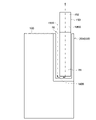
- FIG. 2 is a diagram schematically showing the physical configuration of the suction device 100 according to the present embodiment.
- the suction device 100 has a heater assembly 30 including a heating unit 40 and a holding unit 60.
- the heater assembly 30 in a state where the stick-type base material 150 is held by the heater assembly 30 (more specifically, the holding portion 60), there is a gap between the heater assembly 30 and the stick-type base material 150.
- the air flowing in from the opening 52 flows into the inside of the stick-type base material 150 from the end of the base material portion 151 via the gap, and the air sucking portion 152. It leaks from the end into the user's mouth.
- the air sucked by the user flows in the order of air flow 190A, air flow 190B, and air flow 190C, and is guided into the user's oral cavity in a state of being mixed with the aerosol generated from the stick-type base material 150.
- FIG. 3 shows a perspective view of the heater assembly 30 shown in FIG.
- the heater assembly 30 has a top cap 32, a heating unit 40, and a chamber 50.
- the chamber 50 is configured to receive the stick-type substrate 150.
- the heating unit 40 is configured to heat the stick-type base material 150 received in the chamber 50.
- the top cap 32 has a function of a guide when inserting the stick type base material 150 into the chamber 50, and may be configured to fix the chamber 50 to the suction device 100.
- FIG. 4 shows a perspective view of the chamber 50.
- FIG. 5 shows a cross-sectional view of the chamber 50 in arrow view 4-4 shown in FIG.
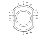
- FIG. 6 shows a cross-sectional view of the chamber 50 in arrow view 5-5 shown in FIG.
- the chamber 50 includes an opening 52 into which the stick-type substrate 150 is inserted and a holding portion 60 for holding the stick-type substrate 150.
- the chamber 50 is formed as a hollow member that surrounds the interior space 80 that receives the stick-type substrate 150.
- the hollow member can be a bottomed tubular member.
- the hollow member may be a cylindrical body without a bottom.
- the chamber 50 is preferably made of a metal having a high thermal conductivity, and may be made of, for example, stainless steel. This enables effective heating from the chamber 50 to the stick-type substrate 150.
- the holding portion 60 includes a pressing portion 62 that presses a part of the stick-type base material 150 and a non-pressing portion 66.
- the pressing portion 62 has an inner surface 62a and an outer surface 62b.
- the non-pressing portion 66 has an inner surface 66a and an outer surface 66b.
- the heating unit 40 is arranged on the outer surface 62b of the pressing unit 62. It is preferable that the heating portion 40 is arranged without a gap on the outer surface 62b of the pressing portion 62.
- the opening 52 of the chamber 50 is acceptable without pressing the stick-type base material 150.
- the shape of the opening 52 of the chamber 50 in a plane orthogonal to the longitudinal direction of the chamber 50, in other words the direction in which the stick-shaped substrate 150 is inserted into the chamber 50 or the direction in which the entire side surface of the chamber 50 extends, is polygonal or elliptical. It may be, but it is preferably circular.
- the chamber 50 has two or more pressing portions 62 in the circumferential direction of the chamber 50.
- the two pressing portions 62 of the holding portion 60 face each other. It is preferable that at least a part of the distance between the inner surfaces 62a of the two pressing portions 62 is smaller than the width of the portion arranged between the pressing portions 62 of the stick type base material 150 inserted into the chamber 50.
- the inner surface 62a of the pressing portion 62 is a flat surface.
- the inner surface 62a of the pressing portion 62 has a pair of planar pressing surfaces facing each other, and the inner surface 66a of the non-pressing portion 66 connects both ends of the pair of planar pressing surfaces and faces each other. It has a curved non-pressing surface. As shown, the curved non-pressing surface may have an overall arcuate cross section in a surface orthogonal to the longitudinal direction of the chamber 50. As shown in FIG. 6, the holding portion 60 is composed of a metal cylinder having a uniform thickness.
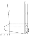
- FIG. 7 is a vertical sectional view of the chamber 50 including the non-pressing portion 66 in a state where the stick type base material 150 is held by the holding portion 60.
- FIG. 8 is a vertical sectional view of the chamber 50 including the pressing portion 62 in a state where the stick type base material 150 is held by the holding portion 60.
- FIG. 9 is a cross-sectional view of the chamber 50 in arrow view 7-7 shown in FIG. Note that FIG. 9 shows a cross section of the stick-type base material 150 in a state before being pressed so that it is easy to understand that the stick-type base material 150 is pressed by the pressing portion 62.
- the stick-type base material 150 is held by the holding portion 60, and the stick-type base material 150 is held by the pressing portion 62. Even if it is pressed and deformed by, it is substantially maintained.
- the gap 67 can communicate with the opening 52 of the chamber 50 and the end face of the stick-type base material 150 positioned in the chamber 50 (the lower end face in FIGS. 7 and 8, that is, the end face of the base material portion 151). ..
- the gap 67 is the opening 52 of the chamber 50 and the end face of the stick-type base material 150 positioned in the chamber 50 and located far from the opening 52 of the chamber 50 (the lower end face in FIGS. 7 and 8, that is, the lower end face). It can also be said that it communicates with the end face of the base material portion 151). Then, from the opening 52 of the chamber 50 to the end face of the stick-type base material 150 positioned outside the chamber 50 (the upper end face in FIGS. 7 and 8, that is, the end face of the mouthpiece 152), the gap 67 and the stick-type base material 150 are extended. An air flow path is formed through the interior of the air.
- the suction device 100 As a result, it is not necessary to separately provide the suction device 100 with a flow path for introducing the air supplied to the stick-type base material 150, so that the structure of the suction device 100 can be simplified. Further, since the portion of the non-pressing portion 66 forming a part of the gap 67 is exposed, the flow path can be easily cleaned. Further, since the air is heated in the process of passing the air through the void 67, the heat radiation by the heating unit 40 is effectively utilized to improve the heating efficiency, and the stick-type base material 150 due to the air flowing in with the puff is excessive. It is possible to prevent the temperature from falling.
- the height of the gap 67 between the inner surface 66a of the non-pressing portion 66 and the stick-type base material 150 is preferably 0.1 mm or more and 1.0 mm or less, and 0.2 mm or more and 0. It is more preferably 8.8 mm or less, and most preferably 0.3 mm or more and 0.5 mm or less.
- the distance LA between the inner surface 62a of the pressing portion 62 and the center of the stick - type base material 150 is the inner surface of the non-pressing portion 66.
- the distance between 66a and the center of the stick - type base material 150 is shorter than the distance LB.
- the chamber 50 has a bottom 56.
- the bottom portion 56 supports a part of the stick-type base material 150 inserted into the chamber 50 by the bottom wall 56a so as to expose at least a part of the end face of the stick-type base material 150. .. Further, the bottom portion 56 may support a part of the stick-type base material 150 by the bottom wall 56a so that the end face of the exposed stick-type base material 150 communicates with the void 67.
- the bottom 56 of the chamber 50 may have a bottom wall 56a and, in addition, a side wall 56b.
- the width of the bottom 56 defined by the side wall 56b may decrease towards the bottom wall 56a.
- the inner surface 66a of the non-pressing portion 66 of the holding portion 60 is curved in a plane orthogonal to the longitudinal direction of the chamber 50.
- the shape of the inner surface 66a of the non-pressing portion 66 on the surface orthogonal to the longitudinal direction of the chamber 50 is the same as the shape of the opening 52 on the surface orthogonal to the longitudinal direction of the chamber 50 at any position in the longitudinal direction of the chamber 50. Is preferable.
- the inner surface 66a of the non-pressing portion 66 is preferably formed by extending the inner surface of the chamber 50 forming the opening 52 in the longitudinal direction.
- the chamber 50 has a cylindrical non-holding portion 54 between the opening 52 and the holding portion 60.
- a gap may be formed between the non-holding portion 54 and the stick-type base material 150.
- the outer peripheral surface of the holding portion 60 has the same shape and size (the holding portion 60 on the surface orthogonal to the longitudinal direction of the holding portion 60) over the entire length in the longitudinal direction of the holding portion 60. It is preferable to have an outer peripheral length).
- the chamber 50 has a first guide portion 58 provided with a tapered surface 58a connecting the inner surface of the chamber 50 forming the opening 52 and the inner surface 62a of the pressing portion 62. Is preferable.
- the heating unit 40 has a heating element 42.
- the heating element 42 may be, for example, a heating track.
- the outer surface 62b of the pressing portion 62 and the outer surface 66b of the non-pressing portion 66 are connected to each other at an angle, and the outer surface 62b of the pressing portion 62 and the outer surface 66b of the non-pressing portion 66 are connected to each other.
- a boundary 71 may be formed between them.
- the heating track preferably extends in a direction intersecting the extending direction of the boundary 71 (longitudinal direction of the chamber), and preferably extends in a direction perpendicular to the extending direction of the boundary 71.
- the heating unit 40 has, in addition to the heating element 42, an electrical insulating member 44 that covers at least one surface of the heating element 42.
- the electrical insulating member 44 is arranged so as to cover both sides of the heating element. Further, it is preferable that the electrical insulating member 44 is arranged in the region of the outer surface of the holding portion 60. In other words, it is preferable that the electrically insulating member 44 is arranged so as not to protrude from the outer surface of the holding portion 60 on the side of the first guide portion 58 in the longitudinal direction of the chamber 50.
- the first guide portion 58 is provided between the opening 52 and the pressing portion 62, the shape of the outer surface of the chamber 50 and the surface of the chamber orthogonal to the longitudinal direction of the chamber in the longitudinal direction of the chamber 50 are provided.
- the outer circumference length can change. Therefore, by arranging the electrical insulating member 44 on the outer surface of the holding portion 60, it is possible to suppress the occurrence of slack.
- the heating portion 40 is at least one selected from the outer surface of the chamber 50 between the opening 52 and the first guide portion 58, that is, the outer surface of the non-holding portion 54, the outer surface of the first guide portion 58, and the outer surface of the non-pressing portion 66. It is preferable that they are not arranged in one.
- the heating portion 40 is preferably arranged over the entire outer surface 62b of the pressing portion 62.
- the suction device 100 has a strip-shaped electrode 48 extending from the heating unit 40. It is preferable that the strip-shaped electrode 48 extends from the outer surface 62b of the flat pressing portion 62 to the outside of the outer surface 62b of the pressing portion 62 in a state where the heating portion 40 is arranged on the outer surface 62b of the pressing portion 62.
- the heating unit 40 has a first portion 40a located on the opposite side of the opening 52 and a second portion 40b located on the opening 52 side.
- the heater power density of the second portion 40b is preferably higher than the heater power density of the first portion 40a.
- the rate of temperature rise of the second portion 40b is preferably higher than the rate of temperature rise of the first portion 40a.
- the heating temperature of the second portion 40b is preferably higher than the heating temperature of the first portion 40a at any same time.
- the second portion 40b is a holding portion corresponding to 1/2 or more of the smokeable material in the longitudinal direction of the smokeable material contained in the stick-type base material 150 in a state where the stick-type base material 150 is held by the holding portion 60. It is preferable to cover the outer surface of 60.
- the chamber 50 has a pair of pressing portions 62 facing each other, but the shape of the chamber is not limited to this.
- the chamber 50 may have one pressing portion 62 or may have three or more pressing portions 62.
- the suction device 100 holds and heats the stick-type base material 150 while pressing it by the pressing portion 62. With such a configuration, various effects described below are produced.
- the thermal conductivity from the heating unit 40 to the stick-type base material 150 is improved. That is, the heating efficiency of the stick-type base material 150 can be improved. Since the heating efficiency of the stick-type base material 150 is improved, the temperature of the stick-type base material 150 can be reached to the target temperature quickly, so that the time required for preheating, which will be described later, can be shortened. Further, since the heating efficiency of the stick-type base material 150 is improved, the temperature followability of the stick-type base material 150 to the temperature change of the heating unit 40 can be improved. As a result, firstly, it is possible to more easily control the amount of aerosol produced.
- the temperature of the stick-type base material 150 can be immediately returned to the original temperature.
- the influence of the external environment such as the outside air temperature can be reduced.
- the effect of improving the flavor which is the effect of the reheating section described later in the heating profile, can be rapidly produced.
- the suction device 100 heats from the outer periphery while pressing the stick type base material 150.
- the above-mentioned improvement of the heating efficiency of the stick-type base material 150 and the improvement of the temperature followability of the stick-type base material 150 can be realized. Can be done.
- the heating efficiency of the stick-type base material 150 described above is improved regardless of the error in the shape or size of the stick-type base material 150 due to the variation generated in the manufacturing process of the stick-type base material 150.
- the temperature followability of the stick-type base material 150 can be improved.
- the heat insulating portion 70 is arranged so as to surround the heating portion 40 from the outer periphery.
- the outer surface 62b of the pressing portion 62 is located closer to the center of the internal space 80 than the outer surface 66b of the non-pressing portion 66, between the outer surface 62b of the pressing portion 62 and the inner surface of the heat insulating portion 70.
- the thickness of the formed air layer can be increased.
- the thickness of the heat insulating portion 70 superimposed on the pressing portion 62 can be increased. Therefore, the heat insulating effect of the heat insulating portion 70 can be improved.
- the suction device 100 controls the operation of the heating unit 40 based on the heating profile.
- the heating profile is information that defines the time-series transition of the target temperature, which is the target value of the temperature of the heating unit 40.
- the suction device 100 controls the operation of the heating unit 40 so that the time-series transition of the target temperature specified in the heating profile is realized. This produces the aerosol as planned by the heating profile.
- the heating profile is typically designed to optimize the flavor the user tastes when the user inhales the aerosol produced from the stick-type substrate 150. Therefore, by controlling the operation of the heating unit 40 based on the heating profile, the flavor to be tasted by the user can be optimized.
- the control unit 116 controls the operation of the heating unit 40 based on the difference between the target temperature specified in the heating profile and the actual temperature of the heating unit 40 (hereinafter, also referred to as the actual temperature). More specifically, the control unit 116 operates the heating unit 40 based on the difference between the target temperature corresponding to the elapsed time from the start of control of the operation of the heating unit 40 based on the heating profile and the actual temperature. To control. The control unit 116 controls the temperature of the heating unit 40 so that the time-series transition of the actual temperature of the heating unit 40 becomes the same as the time-series transition of the target temperature of the heating unit 40 defined in the heating profile.
- the temperature control of the heating unit 40 can be realized by, for example, a known feedback control.
- control unit 116 supplies the electric power from the power supply unit 111 to the heating unit 40 in the form of a pulse by pulse width modulation (PWM) or pulse frequency modulation (PFM).
- PWM pulse width modulation
- PFM pulse frequency modulation
- the control unit 116 can control the temperature of the heating unit 40 by adjusting the duty ratio of the power pulse.
- the control unit 116 may control the electric power supplied to the heating unit 40, for example, the duty ratio described above, based on the difference between the actual temperature and the target temperature.
- the feedback control may be, for example, PID control (Proportional-Integral-Differential Controller).
- the control unit 116 may perform simple ON-OFF control. For example, the control unit 116 executes heating by the heating unit 40 until the actual temperature reaches the target temperature, stops heating by the heating unit 40 when the actual temperature reaches the target temperature, and the actual temperature is lower than the target temperature. Then, the heating by the heating unit 40 may be executed again.
- the temperature of the heating unit 40 can be quantified, for example, by measuring or estimating the electric resistance value of the heat-generating resistor constituting the heating unit 40. This is because the electric resistance value of the heat generation resistor changes according to the temperature.
- the electric resistance value of the heat-generating resistor can be estimated, for example, by measuring the amount of voltage drop in the heat-generating resistor.
- the amount of voltage drop in the heat-generating resistor can be measured by a voltage sensor that measures the potential difference applied to the heat-generating resistor.
- the temperature of the heating unit 40 can be measured by a temperature sensor installed near the heating unit 40.
- Heating based on the heating profile starts from the timing when it is detected that the operation instructing the start of heating has been performed.
- An example of an operation for instructing the start of heating is pressing a button provided on the suction device 100.
- Another example of an operation instructing the start of heating is a puff operation.
- Another example of the operation of instructing the start of heating is the reception of a signal from another device such as a smartphone.
- the aerosol source contained in the substrate gradually decreases with the passage of time.
- heating by the heating unit 40 is stopped at a timing when the aerosol source is expected to be exhausted.
- An example of the timing at which the aerosol source is assumed to be exhausted is the timing at which a predetermined time has elapsed since the control of the operation of the heating unit 40 based on the heating profile was started.
- An example of the timing at which the aerosol source is expected to be depleted is the timing at which a predetermined number of puffs are detected.
- An example of the timing at which the aerosol source is assumed to be exhausted is the timing at which the button provided on the suction device 100 is pressed. Such a button is pressed, for example, when the user can no longer feel a sufficient flavor.
- the period during which a sufficient amount of aerosol is expected to be generated is also called the puffable period.
- the period from the start of heating to the start of the puffable period is also referred to as a preheating period.
- the heating performed during the preheating period is also referred to as preheating.
- the user may be notified when the puffable period starts and ends. In that case, the user can puff during the puffable period with reference to the notification.
- the control unit 116 controls the operation of the heating unit 40 based on the holding state of the stick-type base material 150 by the holding unit 60.
- the control unit 116 is a heating unit 40 so that the stick-type base material 150 is heated based on the heating profile in a state where a part of the stick-type base material 150 is pressed by the pressing unit 62 of the holding unit 60.
- Control the operation That is, the control unit 116 has an elapsed time from the start of controlling the operation of the heating unit 40 based on the heating profile in a state where a part of the stick-type base material 150 is pressed by the pressing unit 62 of the holding unit 60.
- the amount of power supplied to the heating unit 40 is adjusted according to the corresponding target temperature, and the heating of the stick-type base material 150 by the heating unit 40 is controlled. At that time, the control unit 116 may further adjust the feeding amount according to the strength of the pressing by the pressing unit 62. Further, the control unit 116 is a heating unit so as not to heat the stick-type base material 150 based on the heating profile when a part of the stick-type base material 150 is not pressed by the pressing unit 62 of the holding unit 60. The operation of 40 may be controlled (for example, power supply to the heating unit 40 is not performed).
- the operation of the heating unit 40 is controlled according to the degree of improvement of the heating efficiency of the stick-type base material 150 by such a configuration. Is possible. Therefore, it is possible to provide the user with a sufficient quality puff experience.
- the heating profile includes a plurality of continuous time intervals along the time axis.
- a target temperature at the end of the time interval is set for each of the plurality of time intervals.
- the control unit 116 sets the target temperature, the actual temperature, and the target temperature set in the time interval corresponding to the elapsed time from the start of the control of the operation of the heating unit 40 based on the heating profile among the plurality of time intervals.
- the operation of the heating unit 40 is controlled based on the deviation between the two. Specifically, the control unit 116 controls the operation of the heating unit 40 so as to reach the set target temperature by the end of each of the plurality of time intervals included in the heating profile.
- Table 1 An example of the heating profile is shown in Table 1 below.
- the heating profile shown in Table 1 consists of an initial temperature rise section, an intermediate temperature drop section, and a re-heat rise section, and includes these in order.
- the initial temperature rise section is a section from the start of the heating profile to 35 seconds later.
- the intermediate temperature drop section is a section from the end of the initial temperature rise section to 10 seconds later.
- the re-heating section is a section from the end of the intermediate temperature-decreasing section to 310 seconds later.
- the initial temperature rise section is the time section included at the beginning of the heating profile.
- the target temperature set in the initial temperature rise section is higher than the initial value.
- the initial value is a temperature assumed as the temperature of the heating unit 40 before the start of heating.
- An example of the initial value is an arbitrary temperature such as 0 ° C.
- Another example of the initial value is the temperature corresponding to the air temperature.
- the midway temperature drop section is a time section included in the middle of the heating profile.
- the target temperature set in the intermediate temperature drop section is lower than the target temperature set in the time interval immediately before the intermediate temperature decrease section.
- the target temperature 230 ° C. set in the intermediate temperature drop section is lower than the target temperature 295 ° C. set in the initial temperature rise section which is the previous time section.
- the reheating section is the time section included at the end of the heating profile.
- the target temperature set in the reheating section is higher than the target temperature set in the time section immediately before the reheating section.
- the target temperature of 260 ° C. set in the re-heating section is higher than the target temperature of 230 ° C. set in the intermediate temperature-decreasing section, which is the previous time section.
- FIG. 10 is a graph showing an example of time-series transition of the actual temperature of the heating unit 40 operated based on the heating profile shown in Table 1.
- the horizontal axis of this graph is time (seconds).
- the vertical axis of this graph is the temperature of the heating unit 40.
- the line 21 in this graph shows the time-series change of the actual temperature of the heating unit 40.
- the actual temperature of the heating unit 40 rises in the initial temperature rise section and reaches the target temperature of 295 ° C. at the end of the initial temperature rise section.
- the actual temperature of the heating unit 40 reaches the target temperature set in the initial temperature rise section, it is assumed that the temperature of the stick-type base material 150 reaches the temperature at which a sufficient amount of aerosol is generated.
- the initial temperature rise section is set at the beginning of the heating profile. Therefore, in the initial temperature rise section, the heating unit 40 is heated at once from the initial temperature to 295 ° C., which is the target temperature set in the initial temperature rise section.
- the initial temperature is the actual temperature of the heating unit 40 at the start of heating based on the heating profile. With such a configuration, it is possible to finish the preheating at an early stage.
- the control unit 116 controls the temperature of the heating unit 40 so that the actual temperature reaches the target temperature set in the initial temperature rise section in the initial temperature rise section. That is, the control unit 116 controls the temperature of the heating unit 40 from the initial temperature toward 295 ° C. If the actual temperature reaches 295 ° C. before 35 seconds have elapsed from the start of heating, the control unit 116 controls the temperature of the heating unit 40 so as to maintain 295 ° C.
- the actual temperature of the heating unit 40 drops in the intermediate temperature decrease section and reaches the target temperature of 230 ° C. at the end of the intermediate temperature decrease section.
- the intermediate temperature drop section is set next to the initial temperature rise section. Therefore, the heating unit 40 temporarily lowers the temperature from the set temperature in the initial temperature rise section to the set temperature in the middle temperature drop section in the intermediate temperature decrease section. If the heating unit 40 is maintained at a high temperature such as the target temperature in the initial temperature rise section, the aerosol source contained in the stick-type base material 150 is rapidly consumed, and the user's taste is too strong. Occurs. In that respect, in the present embodiment, it is possible to avoid such inconvenience and improve the quality of the user's puff experience by providing an intermediate temperature drop section.
- the control unit 116 controls so as not to supply power to the heating unit 40 in the middle temperature drop section. That is, the control unit 116 stops the power supply to the heating unit 40 in the intermediate temperature drop section, and controls so that the heating unit 40 does not heat. According to such a configuration, the actual temperature of the heating unit 40 can be lowered at the earliest. Further, it is also possible to reduce the power consumption of the suction device 100 as compared with the case where power is supplied to the heating unit 40 even in the middle temperature drop section.
- the actual temperature of the heating unit 40 rises in the reheating section and reaches the target temperature of 260 ° C. at the end of the reheating section.
- the re-heating section is next to the intermediate temperature-decreasing section and is set at the end of the heating profile. Therefore, in the reheating section, the heating unit 40 is heated again from the set temperature in the intermediate temperature lowering section to the set temperature in the reheating section, and then stops heating. If the temperature of the heating unit 40 is continuously lowered after the initial temperature rise section, the temperature of the stick-type base material 150 is also lowered, so that the amount of aerosol produced is reduced and the flavor tasted by the user may be deteriorated. In that respect, in the present embodiment, it is possible to prevent the deterioration of the flavor tasted by the user even in the latter half of the heating profile by providing the re-heating section after the intermediate temperature lowering section.
- the control unit 116 controls the temperature of the heating unit 40 so that the actual temperature reaches the target temperature set in the reheating section in the reheating section. That is, the control unit 116 controls the temperature of the heating unit 40 toward 260 ° C. If the actual temperature reaches 260 ° C. before 310 seconds have elapsed from the start of the reheating section, the control unit 116 controls the temperature of the heating unit 40 so as to maintain 260 ° C.
- the re-heat rise section When comparing the absolute values of the amount of change in the target temperature per unit time for each of the initial temperature rise section, the intermediate temperature drop section, and the re-heat rise section, the re-heat rise section is the smallest, and the intermediate temperature drop section is the next smallest.
- the initial temperature rise section may be the largest.
- the absolute value of the amount of change in the target temperature per unit time in the initial temperature rise section is the absolute value of the difference between the target temperature set in the initial temperature rise section and the initial value divided by the time length of the initial temperature rise section. Is.
- the absolute value of the amount of change in the target temperature per unit time in the intermediate temperature drop section is the target set in the intermediate temperature drop section and the target set in the time interval immediately before the intermediate temperature drop section (for example, the initial temperature rise section).
- the absolute value of the amount of change in the target temperature per unit time in the reheating section is set in the time section immediately before the target temperature set in the reheating section and the reheating section (for example, the intermediate temperature drop section). It is the value obtained by dividing the absolute value of the difference from the target temperature by the time length of the reheating section. Further, when comparing the time lengths of each of the initial temperature rise section, the intermediate temperature decrease section, and the re-heat rise section, the intermediate temperature decrease section is the shortest, the initial temperature rise section is the next shortest, and the re-heat rise section is the shortest. The longest.
- the heating unit 40 rapidly raises the temperature in the initial temperature rise section, quickly escapes from the high temperature state in the intermediate temperature drop section, and slowly raises the temperature in the re-heat rise section. Will be. Therefore, it is possible to finish the preheating early and to provide the user with a sufficient quality puff experience from the beginning to the end of the heating profile.
- the control unit 116 may determine at least a part of the switching of a plurality of time intervals in the heating profile based on the actual temperature of the heating unit 40. For example, the control unit 116 determines the difference between the target temperature set in each time section and the actual temperature of the heating unit 40 for switching from the initial temperature rise section to the intermediate temperature drop section and ending the re-heating section. The determination may be made based on the fact that the temperature is within the threshold value of.
- the control unit 116 may determine at least a part of the switching of a plurality of time intervals in the heating profile based on the elapsed time. For example, the control unit 116 may determine the end of the intermediate temperature drop section based on the elapsed time from the start of the intermediate temperature decrease section. For example, in the heating profile shown in FIG. 10, the intermediate temperature drop section is set to 10 seconds. Therefore, the control unit 116 determines the switching to the re-heating section and restarts the heating by the heating unit 40 when 10 seconds have elapsed from the start of the intermediate temperature lowering section.
- the actual temperature of the heating unit 40 at the end of the intermediate temperature drop section may fluctuate depending on the external environment such as the outside air temperature.
- the actual temperature of the heating unit 40 at the end of the intermediate temperature drop section is 220 ° C. when the outside air temperature is low and 240 ° C. when the outside air temperature is high. Can be.
- the control unit 116 is the heating unit based on the actual temperature of the heating unit 40 and the target temperature set in the intermediate temperature decrease section at the beginning of the time section (that is, the re-heating section) next to the intermediate temperature decrease section. Controls the operation of 40. More specifically, the control unit 116 heats at the first duty ratio when the actual temperature of the heating unit 40 is less than the target temperature set in the intermediate temperature decrease section at the beginning of the time interval next to the intermediate temperature decrease section. Power is supplied to the unit 40. On the other hand, the control unit 116 sets the heating unit 40 at the second duty ratio when the actual temperature of the heating unit 40 is equal to or higher than the target temperature set in the intermediate temperature decrease section at the beginning of the time section next to the intermediate temperature decrease section. Power to.
- the first duty ratio is larger than the second duty ratio.
- the duty ratio is the ratio of the period during which the power supply to the heating unit 40 is continued in a predetermined period. According to such a configuration, even if a deviation occurs between the target temperature of the heating unit 40 and the actual temperature due to the influence of the external environment, the deviation can be quickly reduced, so that the flavor to be tasted by the user can be enjoyed. It is possible to suppress deterioration.
- FIG. 11 is a flowchart showing an example of a process flow executed by the suction device 100 according to the present embodiment.
- the suction device 100 raises the temperature of the heating unit 40 from the initial temperature to the target temperature set in the initial temperature rise section in the initial temperature rise section (step S102).
- the suction device 100 stops the power supply to the heating unit 40 in the intermediate temperature drop section, and lowers the temperature of the heating unit 40 to the target temperature set in the intermediate temperature decrease section (step S104).
- the suction device 100 raises the temperature of the heating unit 40 to the target temperature set in the reheating section in the reheating section (step S106).
- the suction device 100 stops supplying power to the heating unit 40 at the same time as the reheating section ends (step S108).
- a heating profile is provided in which the temperature rise range per unit time gradually decreases in the initial temperature rise section. With such a configuration, it is possible to avoid overshoot in the initial temperature rise section and improve the quality of the user's puff experience.
- Table 2 shows an example of the heating profile in this modification.
- FIG. 12 is a graph showing an example of the time-series transition of the actual temperature of the heating unit 40 operated based on the heating profile shown in Table 2.
- the horizontal axis of this graph is time (seconds).
- the vertical axis of this graph is the temperature of the heating unit 40.
- the line 21 in this graph shows the time-series change of the actual temperature of the heating unit 40.
- the initial temperature rise section includes a first temperature rise section and a second temperature rise section following the first temperature rise section.
- Different target temperatures are set for each of the first temperature rise section and the second temperature rise section. Therefore, as shown in FIG. 12, the control unit 116 controls the operation of the heating unit 40 so as to reach the target temperature of 290 ° C. in the first temperature rise section, and then controls the operation of the heating unit 40 so as to reach the target temperature in the second temperature rise section.
- the operation of the heating unit 40 is controlled so as to reach 295 ° C.
- the temperature rise range per unit time differs between the first temperature rise section and the second temperature rise section.
- the temperature rise width per unit time of the first temperature rise section is a value obtained by dividing the difference between the target temperature set in the first temperature rise section and the initial value by the time length of the first temperature rise section. .. Assuming that the initial value is 0 ° C., the temperature rise range per unit time of the first temperature rise section in the example shown in Table 2 is (290-0) / 17 ⁇ 17.
- the temperature rise range per unit time in the second temperature rise section is the difference between the target temperature set in the second temperature rise section and the target temperature set in the first temperature rise section. It is the value divided by the time length of the section. In the example shown in Table 2, the temperature rise width per unit time of the second temperature rise section is (295-290) /18 ⁇ 0.3.
- the temperature rise range per unit time is smaller in the later temperature rise section than in the previous temperature rise section. That is, the temperature rise range per unit time is smaller in the second temperature rise section than in the first temperature rise section. Therefore, as shown in FIG. 12, the temperature rises slowly as the temperature rises in the latter half of the initial temperature rise section, so that the transition of the actual temperature can be finely controlled as the temperature rises in the latter half of the initial temperature rise section. As a result, overshoot can be prevented.
- the time length of the first temperature rise section and the target temperature set in the first temperature rise section, and the time length of the second temperature rise section and the target temperature set in the second temperature rise section are second.
- the temperature rise width per unit time in the temperature rise section is set to be smaller than the temperature rise width per unit time in the first temperature rise section.
- the length of the second temperature rise section may be longer than the length of the first temperature rise section.
- the length of the second temperature rise section is 18 seconds, which is longer than the length of the first temperature rise section of 17 seconds.
- the temperature rise width in the second temperature rise section may be smaller than the temperature rise width in the first temperature rise section.
- the initial temperature rise section may further include a temperature maintenance section.
- An example of the heating profile in that case is shown in Table 3.
- FIG. 13 is a graph showing an example of the time-series transition of the actual temperature of the heating unit 40 operated based on the heating profile shown in Table 3.
- the horizontal axis of this graph is time (seconds).
- the vertical axis of this graph is the temperature of the heating unit 40.
- the line 21 in this graph shows the time-series change of the actual temperature of the heating unit 40.
- the initial temperature rise section includes the temperature maintenance section at the end in addition to the first temperature rise section and the second temperature rise section.
- the target temperature set in the temperature maintenance section is the same as the target temperature set in the time section immediately before the temperature maintenance section. Therefore, as shown in FIG. 13, the control unit 116 raises the temperature to 290 ° C. in the first temperature rise section for 17 seconds, raises the temperature to 295 ° C. in the subsequent second temperature rise section for 18 seconds, and further succeeds.
- the operation of the heating unit 40 is controlled so as to maintain 295 ° C. in the temperature maintenance section for 10 seconds.
- the temperature of the stick-type base material 150 can be sufficiently raised to the inside in the temperature maintenance section. Therefore, since the stick-type base material 150 has not been sufficiently heated to the inside, a situation may occur in which a poor taste is delivered to the user in the subsequent intermediate temperature lowering section and re-heating section. It becomes possible to prevent.
- the number of temperature rise sections included in the initial temperature rise section is not limited to two.
- the initial temperature rise section may have three or more temperature rise sections. In that case, in the plurality of temperature rise sections included in the initial temperature rise section, the temperature rise range per unit time becomes smaller in the later temperature rise section as compared with the previous temperature rise section.
- the re-heat rise section is the smallest and the intermediate temperature decrease is achieved. It is desirable that the section is the next smallest and the initial temperature rise section is the largest. In particular, it is desirable that the absolute value of the amount of change in the target temperature per unit time is the smallest in the re-heating section, the next smallest in the intermediate temperature-decreasing section, and the largest in the first rising section.
- the intermediate temperature decrease section is the shortest
- the initial temperature rise section is the next shortest
- the re-heat rise section is the shortest.
- the longest is desirable.
- the time length of the time section is the shortest in the intermediate temperature drop section, the next shortest in the first temperature rise section, and the longest in the re-heat rise section.
- the temperature maintenance section is included in the initial temperature rise section, but it may be considered that the temperature maintenance section is included between the initial temperature rise section and the intermediate temperature decrease section. That is, the heating profile consists of an initial temperature rise section, a temperature maintenance section, an intermediate temperature drop section, and a re-heat rise section, and may include these in order. Even in that case, the effects described above are similarly produced.
- a temperature maintenance section may be provided at the end of the initial temperature rise section, and a temperature maintenance section may be provided between the initial temperature rise section and the intermediate temperature drop section.
- Second variant> When the temperature of the stick-type base material 150 rises rapidly, the aerosol source contained in the stick-type base material 150 is rapidly consumed, so that the flavor that the user tastes is too strong or the aerosol source is quickly depleted. , Can cause inconvenience.
- a heating profile including a stepwise temperature rise section which is a time section in which the target temperature rises stepwise.
- FIG. 14 is a graph showing an example of the time-series transition of the actual temperature of the heating unit 40 operated based on the heating profile shown in Table 4.
- the horizontal axis of this graph is time (seconds).
- the vertical axis of this graph is the temperature of the heating unit 40.
- the line 21 in this graph shows the time-series change of the actual temperature of the heating unit 40.
- the heating profile includes a reheating section as a stepwise heating section.
- the stepwise temperature rise section consists of a plurality of time sections, and the target temperature set for each of the plurality of time sections included in the stepwise temperature rise section is equal to or higher than the target temperature set for the previous time section (that is,). , Same or greater).
- the target temperature of the first temperature maintenance section included in the re-heating section is 230 ° C, which is the same as the target temperature of the intermediate temperature-decreasing section.
- the target temperature of the temperature rising section included in the reheating section is 260 ° C., which is larger than the target temperature of the first temperature maintaining section.
- the target temperature of the second temperature maintenance section included in the reheating section is 260 ° C., which is the same as the target temperature of the reheating section. Therefore, as shown in FIG. 14, the control unit 116 maintains 230 ° C. in the first temperature maintenance section and raises the temperature to 260 ° C. in the temperature rise section in the reheating section, and the second temperature.
- the operation of the heating unit 40 is controlled so as to maintain 260 ° C. in the maintenance section. With such a configuration, the aerosol is slowly generated in the reheating section, so that the life of the stick-type base material 150 can be extended. Along with this, it becomes possible to draw out sufficient flavor from the stick-type base material 150 until the end of the reheating section.
- the stepwise temperature rise section may include the temperature maintenance section and the temperature rise section alternately.
- the target temperature set in the temperature maintenance section is the same as the target temperature set in the time section immediately before the temperature maintenance section.
- the target temperature set in the temperature rise section is higher than the target temperature set in the time section immediately before the temperature rise section.
- a temperature maintenance section for 135 seconds is provided at the beginning of the reheating section, a temperature maintenance section for 80 seconds is provided next, and a temperature maintenance section for 95 seconds is provided at the end. ..
- the target temperature set in the temperature maintenance section is the same as the target temperature set in the previous time section, even if the actual temperature does not reach the target temperature in the previous time section, It is possible to bring the actual temperature closer to the target temperature in the temperature maintenance section. Therefore, it is possible to improve the followability of the actual temperature with respect to the target temperature throughout the stepwise temperature rise section.
- the number of temperature rise sections included in the stepwise temperature rise section is not limited to one, and may be plural.
- An example of the heating profile in that case is shown in Table 5.
- FIG. 15 is a graph showing an example of time-series transition of the actual temperature of the heating unit 40 operated based on the heating profile shown in Table 5.
- the horizontal axis of this graph is time (seconds).
- the vertical axis of this graph is the temperature of the heating unit 40.
- the line 21 in this graph shows the time-series change of the actual temperature of the heating unit 40.
- "M” is attached to the temperature maintenance section in the reheating section
- "U" is attached to the temperature rising section in the reheating section.
- the heating profile shown in Table 15 includes a re-heating section including a plurality of temperature-maintaining sections M and a heating section U alternately and as a stepwise heating section. Therefore, as shown in FIG. 15, the control unit 116 gradually raises the temperature of the heating unit 40 in a plurality of stages in the reheating section. The control unit 116 starts the next temperature maintenance section M when the temperature rise in the predetermined temperature rise range in the temperature rise section U is completed. It is desirable that the predetermined temperature rise range in one temperature rise section U is suppressed to about several ° C. to about ten and several degrees Celsius.
- the target temperature set in the temperature rising section U is raised within a range not exceeding 260 ° C., which is the target temperature of the reheating section. With such a configuration, it is possible to prevent the life of the stick-type base material 150 from being shortened unnecessarily.
- the temperature rise width in the temperature rise section U may be the same over the entire re-heat temperature section, or may be different, for example, the temperature rise width becomes smaller toward the latter half.
- the control unit 116 may start the next temperature rise section U when it is detected that the user has performed an operation of sucking the aerosol. That is, in the reheating section, the temperature may be raised each time the user puffs, or the temperature may be maintained between the puffs. According to such a configuration, the temperature is raised at the timing when the user puffs, and the amount of flavor extracted increases. Therefore, the flavor that the user tastes can be maintained even in the latter half of the heating profile, so that the user's satisfaction with the puff operation can be improved.
- the control unit 116 may end the temperature maintenance section M and start the next temperature rise section U according to the elapsed time in the temperature maintenance section M.
- the temperature may be raised after the temperature is maintained for a predetermined time.
- the predetermined time is set to a length equivalent to the interval between the puffs that the user has performed in the past. In that case, the same effect as the above-mentioned case where the temperature is raised each time the user puffs is obtained.
- the re-heat rise section (more specifically, re-heat rise section). It is desirable that the average value in the temperature rise section) is the smallest, the intermediate temperature drop section is the next smallest, and the initial temperature rise section is the largest. Further, when comparing the time lengths of each of the initial temperature rise section, the intermediate temperature decrease section, and the re-heat rise section, the intermediate temperature decrease section is the shortest, the initial temperature rise section is the next shortest, and the re-heat rise section is the shortest. The longest is desirable.
- the heating unit 40 rapidly raises the temperature in the initial temperature rise section, quickly escapes from the high temperature state in the intermediate temperature drop section, and slowly raises the temperature in the re-heat rise section. Therefore, it is possible to finish the preheating early and to provide the user with a sufficient quality puff experience from the beginning to the end of the heating profile.
- a variable heating profile is provided according to the input from the user.
- the aerosol can be produced according to the heating profile suitable for the user. Therefore, it is possible to provide a sufficient puff experience to any user.
- the heating profile includes a plurality of slots that are continuous time intervals along the time axis. Then, the control unit 116 controls the operation of the heating unit 40 based on the slot (hereinafter, also referred to as the current slot) corresponding to the elapsed time from the start of the control of the operation of the heating unit 40 based on the heating profile. do.
- the slot hereinafter, also referred to as the current slot
- the target temperature at the end of the slot is set in the slot.
- Controlling the operation of the heating unit 40 based on the slot means controlling the feeding to the heating unit 40 so that the actual temperature reaches the target temperature set in the slot at the end of the slot.
- the control unit 116 controls the operation of the heating unit 40 based on the target temperature set in the slot after the switching.
- the control unit 116 switches the slot when any one of the plurality of switching conditions set in the slot is satisfied, and controls the operation of the heating unit 40 based on the slot after the switching.
- the control unit 116 switches to the slot next to the current slot. According to such a configuration, flexible control based on a plurality of switching conditions becomes possible.
- the multiple switching conditions set for the slot include that the time has elapsed by the length of the slot. That is, the control unit 116 switches from the current slot to the next slot when the time has elapsed by the time length of the current slot after being switched to the current slot.
- the multiple switching conditions set for the slot include the detection of the user sucking the aerosol. That is, the control unit 116 switches to the next slot when the operation of sucking the aerosol by the user is detected. In this case, the control based on the current slot is interrupted and the slot is switched to the next slot. Therefore, the control unit 116 shortens the time length of the heating profile when the operation of sucking the aerosol by the user is detected.
- the time length of the heating profile is the length of the period during which the operation of the heating unit 40 is controlled based on the heating profile. At that time, the control unit 116 shortens the time length of the heating profile by the remaining time length from the timing when the operation of sucking the aerosol by the user is detected to the end of the slot corresponding to the timing.
- Table 6 shows an excerpt of the part of the heating profile that includes four consecutive slots.
- 16 to 18 are graphs showing an example of the time-series transition of the actual temperature of the heating unit 40 operated based on the heating profile shown in Table 6.
- the horizontal axis of this graph is time (seconds).
- the vertical axis of this graph is the temperature of the heating unit 40.
- the line 21 in this graph shows the time-series change of the actual temperature of the heating unit 40.
- FIG. 16 shows the time-series transition of the actual temperature of the heating unit 40 when the puffing operation by the user is not detected in each of the slots S1 to S4.
- each of the slots S1 to S4 is switched to the next slot when the time has elapsed by the time length of the slot.
- another slot having a target temperature of 230 ° C. is continuous in front of the slot S1. Therefore, as shown in FIG. 16, the temperature is raised from 230 ° C. to 235 ° C. in slot S1.
- the temperature is raised to 240 ° C. in slot S2, maintained at 240 ° C. in slot S3, and raised to 245 ° C. in slot S4.
- FIG. 17 shows a time-series transition of the actual temperature of the heating unit 40 when the puffing operation by the user is detected at the time t1 included in the slot S1.
- the control unit 116 terminates the slot S1 at the time t1 and switches to the slot S2. Therefore, as shown in FIG. 17, the control unit 116 controls the operation of the heating unit 40 so that the actual temperature of the heating unit 40 reaches the target temperature of 240 ° C. at the end of the slot S2 after switching. Further, as shown in FIG. 17, since the slot S1 is interrupted in the middle, the time length of the heating profile is shortened by that amount.
- FIG. 18 shows a time-series transition of the actual temperature of the heating unit 40 when the puffing operation by the user is detected at the time t 1 included in the slot S1 and the time t 2 included in the slot S3.
- the control unit 116 terminates the slot S3 at the time t2 and switches to the slot S4. Therefore, as shown in FIG. 18, the control unit 116 controls the operation of the heating unit 40 so that the actual temperature of the heating unit 40 reaches the target temperature of 240 ° C. at the end of the slot S4 after switching. Further, as shown in FIG. 18, since the slot S3 is interrupted in the middle, the time length of the heating profile is shortened by that amount.
- this modification it is possible to control the temperature of the heating unit 40 while switching the slots according to the condition that any one of the plurality of switching conditions set in the slots is satisfied. Become.
- this modification it is possible to control the temperature of the heating unit 40 while switching the slots according to the detection of the puffing operation by the user. According to such a configuration, it is possible to perform fine temperature control according to the puff interval by the user.
- At least a part of the plurality of slots included in the heating profile may have different target temperatures between two consecutive slots.
- the target temperature of slot S1 is 235 ° C
- the target temperature of slot S2 is 240 ° C, which is different from 235 ° C.
- the heating unit 40 can be continuously heated every time the user puffs, so that the flavor tasted by the user can be improved.
- the target temperature may be the same between two consecutive slots in at least a part of the plurality of slots included in the heating profile.
- the target temperature of the slot S2 is 240 ° C.
- the target temperature of the slot S4 is also 240 ° C. According to such a configuration, the temperature of the heating unit 40 can be maintained even if the user puffs, so that the life of the stick-type base material 150 can be extended.
- the target temperature set in the slot is equal to or higher than the target temperature of the slots set in other consecutive slots in front of the slot. That is, the target temperature set in the later slot is not set to a smaller value than the target temperature set in the previous slot, but is set to the same value or a larger value. With such a configuration, it is possible to maintain or raise the temperature each time the user puffs to maintain or improve the flavor that the user tastes.
- the number of slots is 2 or more. If the number of slots is too small, fine temperature control becomes difficult, and the flavor that the user tastes may deteriorate. In that respect, according to such a configuration, since the number of slots can be prevented from being too small, it is possible to prevent deterioration of the flavor tasted by the user.
- the number of slots is 15 or less. If the number of slots is too large, the slots are frequently switched, and the processing load on the control unit 116 increases. In that respect, according to such a configuration, since the number of slots can be prevented from being too large, it is possible to reduce the processing load of the control unit 116.
- the slot time length is 10 seconds or more. If the slot time length is too short, slot switching occurs frequently by that amount, and the processing load on the control unit 116 increases. In that respect, according to such a configuration, the time length of the slot can be prevented from being too short, so that the processing load of the control unit 116 can be reduced.
- the slot time length is less than 25 seconds. If the slot time is too long, fine temperature control becomes difficult, and the flavor that the user tastes may deteriorate. In that respect, according to such a configuration, since the time length of the slot can be prevented from being too long, it is possible to prevent deterioration of the flavor tasted by the user.
- the time lengths of at least two slots of the plurality of slots included in the heating profile may be different from each other. According to such a configuration, fine temperature control becomes possible.
- the time lengths of at least two slots of the plurality of slots included in the heating profile may be the same. According to such a configuration, switching of slots becomes easy, so that the processing load of the control unit 116 can be reduced.
- the slot is set in the reheating section.
- the reheating section is compressed, and the timing of the temperature rise is earlier than in the case where the puff is not performed. Therefore, even when the interval between the puffs of the user is short, the temperature can be sufficiently raised in the re-heating section, so that the user can realize the effect of improving the flavor by the re-heating.
- the re-heat rise section (more specifically, re-heat rise section). It is desirable that the average value in the temperature rise section) is the smallest, the intermediate temperature drop section is the next smallest, and the initial temperature rise section is the largest. Further, when comparing the time lengths of each of the initial temperature rise section, the intermediate temperature decrease section, and the re-heat rise section, the intermediate temperature decrease section is the shortest, the initial temperature rise section is the next shortest, and the re-heat rise section is the shortest. The longest is desirable.
- the heating unit 40 rapidly raises the temperature in the initial temperature rise section, quickly escapes from the high temperature state in the intermediate temperature drop section, and slowly raises the temperature in the re-heat rise section. Therefore, it is possible to finish the preheating early and to provide the user with a sufficient quality puff experience from the beginning to the end of the heating profile.
- the control unit 116 may determine the end of the intermediate temperature decrease section based on the difference between the target temperature set in the intermediate temperature decrease section and the actual temperature of the heating unit 40. For example, the control unit 116 monitors the actual temperature of the heating unit 40 while executing measurements by a temperature sensor installed near the heating unit 40 at a predetermined cycle. Then, when the measured actual temperature reaches the target temperature in the intermediate temperature decrease section, the control unit 116 determines the switching from the intermediate temperature decrease section to the re-increase section. According to such a configuration, it is possible to switch from the intermediate temperature drop section to the re-heat rise section at an appropriate timing regardless of the external environment such as the outside air temperature.
- the control unit 116 controls the operation of the heating unit 40 according to the deviation between the target temperature and the actual temperature.
- the control unit 116 is a target set for the current actual temperature and the current time interval (that is, the time interval corresponding to the elapsed time since the start of control of the operation of the heating unit 40 based on the heating profile).
- the operation of the heating unit 40 may be controlled according to the deviation from the temperature. That is, in the examples shown in Table 1 and FIG. 10, when the actual temperature of the heating unit 40 10 seconds after the start of heating is 100 ° C., the control unit 116 is the difference between 100 ° C. and 295 ° C. 195.
- the operation of the heating unit 40 may be controlled based on the ° C.
- the operation of the heating unit 40 for raising the temperature which is performed when the current actual temperature is lower than the target temperature set in the current time interval, can be realized in various ways.
- the operation of the heating unit 40 for raising the temperature may be controlled based on the remaining time until the end of the time interval and the deviation between the actual temperature and the target temperature. That is, in the examples shown in Table 1 and FIG. 10, when the actual temperature of the heating unit 40 10 seconds after the start of heating is 100 ° C., the control unit 116 raises the temperature by 195 ° C. after 25 seconds.
- the duty ratio of the power pulse supplied to the heating unit 40 may be adjusted.
- the operation of the heating unit 40 for such a temperature rise may be fixed. That is, the control unit 116 may always maximize the duty ratio of the power pulse supplied to the heating unit 40 when the temperature is raised.
- Notification of the timing when the puffable period starts can be performed at any time.
- the notification of the timing at which the puffable period starts may be given at the end of the initial temperature rise section.
- the notification of the timing at which the puffable period starts may be given at the beginning of the temperature maintenance section included in the initial temperature rise section.
- the notification of the timing at which the puffable period starts may be given at the end of the temperature maintenance section.
- the gap formed between the heater assembly 30 and the stick-type base material 150 functions as a flow path for introducing air into the stick-type base material 150
- the present invention has been described. It is not limited to such an example.
- the bottom wall of the heater assembly 30 may be provided with an opening that communicates with the outside air. Then, when the puff is performed by the user, air may be introduced into the stick-type base material 150 through such an opening.
- the modifications described above may be combined as appropriate. That is, at least two of the first modification, the second modification, and the third modification may be combined.
- the first modification and the second modification may be combined. That is, the heating profile may include an initial temperature rise section including a plurality of temperature rise sections having different temperature rise ranges per unit time, an intermediate temperature decrease section, and a re-heat rise section in which the target temperature gradually rises.
- the first modification and the third modification may be combined. In that case, the heating profile may include an initial temperature rise section including a plurality of temperature rise sections having different temperature rise ranges per unit time, an intermediate temperature decrease section, and a reheat temperature section including a plurality of slots.
- each device described in the present specification may be realized by using any of software, hardware, and a combination of software and hardware.
- the programs constituting the software are stored in advance in, for example, a recording medium (non-transitory media) provided inside or outside each device. Then, each program is read into RAM at the time of execution by a computer and executed by a processor such as a CPU.
- the recording medium is, for example, a magnetic disk, an optical disk, a magneto-optical disk, a flash memory, or the like.
- the above computer program may be distributed, for example, via a network without using a recording medium.
- a heating unit that heats the substrate to generate an aerosol
- a control unit that controls the operation of the heating unit based on a heating profile that defines a time-series transition of the target temperature, which is a target value of the temperature of the heating unit. Equipped with The heating profile includes a plurality of continuous time intervals along the time axis. For each of the plurality of time intervals, the target temperature at the end of the time interval is set.
- the heating profile includes an intermediate temperature drop section in the middle. The target temperature set in the intermediate temperature drop section is lower than the target temperature set in the time section immediately before the intermediate temperature decrease section.
- the control unit controls so as not to supply power to the heating unit in the intermediate temperature drop section. Suction device.
- the control unit controls the operation of the heating unit based on the actual temperature of the heating unit and the target temperature set in the intermediate temperature decrease section at the beginning of the time section next to the intermediate temperature decrease section.
- the control unit has the first duty ratio when the actual temperature of the heating unit is lower than the target temperature set in the intermediate temperature drop section at the beginning of the time section following the intermediate temperature decrease section. Power is supplied to the heating unit, and when the actual temperature of the heating unit is equal to or higher than the target temperature set in the intermediate temperature drop section, power is supplied to the heating unit at the second duty ratio. The first duty ratio is larger than the second duty ratio.
- the control unit determines the end of the intermediate temperature drop section based on the elapsed time from the start of the intermediate temperature decrease section.
- the suction device according to any one of (1) to (3) above.
- the control unit determines the end of the intermediate temperature decrease section based on the difference between the target temperature set in the intermediate temperature decrease section and the actual temperature of the heating unit.
- the suction device according to any one of (1) to (3) above.
- the heating profile initially includes an initial temperature rise section.
- the target temperature set in the initial temperature rise section is higher than the initial value.
- the suction device according to any one of (1) to (5) above.
- the initial temperature rise section includes a first temperature rise section and a second temperature rise section following the first temperature rise section.
- the temperature rise range per unit time differs between the first temperature rise section and the second temperature rise section.
- the temperature rise width per unit time of the first temperature rise section is the time length of the first temperature rise section, which is the difference between the target temperature set in the first temperature rise section and the initial value. It is the value divided by
- the temperature rise range per unit time in the second temperature rise section is the difference between the target temperature set in the second temperature rise section and the target temperature set in the first temperature rise section. Is divided by the time length of the second temperature rising section.
- the second temperature rise section has a smaller temperature rise range per unit time than the first temperature rise section.
- the initial temperature rise section includes the temperature maintenance section at the end.
- the target temperature set in the temperature maintenance section is the same as the target temperature set in the time section immediately before the temperature maintenance section.
- the suction device according to any one of (6) to (8) above.
- the heating profile includes a re-heating section after the intermediate temperature-decreasing section.
- the target temperature set in the reheating section is higher than the target temperature set in the time section immediately before the reheating section.
- the suction device according to any one of (1) to (9) above.
- the re-temperature rise section alternately includes a temperature maintenance section and a temperature rise section.
- the target temperature set in the temperature maintenance section is the same as the target temperature set in the time section immediately before the temperature maintenance section.
- the target temperature set in the temperature rise section is higher than the target temperature set in the time section immediately before the temperature rise section.
- the heating profile includes, in order, the initial temperature rise section, the intermediate temperature drop section, and the re-heat rise section.
- the heating profile includes the initial temperature rise section, the temperature maintenance section, the intermediate temperature drop section, and the reheat temperature section in order.
- the target temperature set in the temperature maintenance section is the same as the target temperature set in the time section immediately before the temperature maintenance section.
- the re-heat rise section is the smallest, and the intermediate temperature decrease is achieved.
- the section is the next smallest, and the initial temperature rise section is the largest.
- the absolute value of the amount of change in the target temperature per unit time in the initial temperature rise section is the absolute value of the difference between the target temperature set in the initial temperature rise section and the initial value in the initial temperature rise section.
- the absolute value of the amount of change in the target temperature per unit time in the intermediate temperature drop section is the target temperature set in the intermediate temperature drop section and the target temperature set in the time section immediately before the intermediate temperature drop section. It is the value obtained by dividing the absolute value of the difference from the above by the time length of the intermediate temperature drop section.
- the absolute value of the amount of change in the target temperature per unit time in the reheating section was set in the time section immediately before the target temperature set in the reheating section and the reheating section. It is a value obtained by dividing the absolute value of the difference from the target temperature by the time length of the reheating section.
- the suction device further comprises a chamber for receiving the substrate.
- the chamber includes an opening into which the substrate is inserted and a holding portion for holding the substrate.
- the holding portion includes a pressing portion that presses a part of the base material and a non-pressing portion.
- the suction device according to any one of (1) to (15) above.
- the heating portion is arranged on the outer surface of the pressing portion.
- the suction device according to (16) above.
- the heating profile includes a plurality of slots that are continuous time intervals along the time axis. A plurality of switching conditions are set in the slot, and a plurality of switching conditions are set.
- the control unit switches the slot when any one of the plurality of switching conditions set in the slot is satisfied, and controls the operation of the heating unit based on the slot after switching.
- the suction device according to any one of (1) to (17) above.
- the control unit of the heating unit is based on the deviation between the target temperature corresponding to the elapsed time from the start of control of the operation of the heating unit based on the heating profile and the actual temperature of the heating unit. Control the operation, The suction device according to any one of (1) to (18) above.
- a control method for controlling a suction device having a heating unit that heats a substrate to generate an aerosol Controlling the operation of the heating unit based on the heating profile in which the time-series transition of the target temperature, which is the target value of the temperature of the heating unit, is defined. Including The heating profile includes a plurality of continuous time intervals along the time axis. For each of the plurality of time intervals, the target temperature at the end of the time interval is set. The heating profile includes an intermediate temperature drop section in the middle. The target temperature set in the intermediate temperature drop section is lower than the target temperature set in the time section immediately before the intermediate temperature decrease section. Controlling the operation of the heating unit includes controlling not to supply power to the heating unit in the intermediate temperature drop section. Control method.
- the heating profile includes a plurality of continuous time intervals along the time axis. For each of the plurality of time intervals, the target temperature at the end of the time interval is set.
- the heating profile includes an intermediate temperature drop section in the middle. The target temperature set in the intermediate temperature drop section is lower than the target temperature set in the time section immediately before the intermediate temperature decrease section. Controlling the operation of the heating unit includes controlling not to supply power to the heating unit in the intermediate temperature drop section. program.
- Suction device 111 Power supply unit 112 Sensor unit 113 Notification unit 114 Storage unit 115 Communication unit 116 Control unit 150 Stick type base material 151 Base material unit 152 Mouthpiece unit 30 Heater assembly 32 Top cap 40 Heating unit 40a 1st part 40b 2nd part 42 Heating element 44 Electrical insulation 48 Electrode 50 Chamber 52 Opening 54 Non-holding part 56 Bottom 56a Bottom wall 56b Side wall 58 First guide part 58a Tapered surface 60 Holding part 62 Pressing part 62a Inner surface 62b Outer surface 66 Non-pressing part 66a Inner surface 66b 67 Void 70 Insulation 80 Internal space
Abstract
[Problem] To provide a mechanism which makes it possible to further improve the quality of experience using an inhalation device. [Solution] Provided is an inhalation device comprising a heating part for heating a base material to generate aerosol and a control part for controlling operation of the heating part on the basis of a heating profile in which a time series transition of a target temperature is specified, the target temperature being a target value for the temperature of the heating part, wherein: the heating profile includes a plurality of time sections continuous along a time axis; in each of the plurality of time sections, the target temperature at the end of each time section is set; the heating profile includes a midway temperature drop section on the way; the target temperature set in the midway temperature drop section is lower than the target temperature set in the time section immediately preceding the midway temperature drop section; and the control part performs control such that the heating part is not supplied with power in the midway temperature drop section.
Description
本発明は、吸引装置、制御方法、及びプログラムに関する。
The present invention relates to a suction device, a control method, and a program.
電子タバコ及びネブライザ等の、ユーザに吸引される物質を生成する吸引装置が広く普及している。例えば、吸引装置は、エアロゾルを生成するためのエアロゾル源、及び生成されたエアロゾルに香味成分を付与するための香味源等を含む基材を用いて、香味成分が付与されたエアロゾルを生成する。ユーザは、吸引装置により生成された、香味成分が付与されたエアロゾルを吸引することで、香味を味わうことができる。
Suction devices that generate substances that are sucked by users, such as electronic cigarettes and nebulizers, are widely used. For example, the suction device uses a substrate containing an aerosol source for producing an aerosol, a flavor source for imparting a flavor component to the produced aerosol, and the like to generate an aerosol to which the flavor component is added. The user can taste the flavor by sucking the aerosol to which the flavor component is added, which is generated by the suction device.
吸引装置は、加熱動作を規定した加熱プロファイルに従って基材を加熱することで、エアロゾルを生成する。加熱プロファイルは、吸引装置を用いた体験の質に大きな影響を与える。そのため、様々な加熱プロファイルが検討されている。例えば、下記特許文献1では、加熱開始後まず最高温に達し、その後徐々に降温する加熱プロファイルが開示されている。
The suction device produces an aerosol by heating the substrate according to the heating profile that defines the heating operation. The heating profile has a significant impact on the quality of the experience with the suction device. Therefore, various heating profiles are being studied. For example, Patent Document 1 below discloses a heating profile in which the maximum temperature is first reached after the start of heating, and then the temperature is gradually lowered.
しかし、吸引装置を用いた体験の質はさらに向上されることが望ましい。
However, it is desirable that the quality of the experience using the suction device be further improved.
そこで、本発明は、上記問題に鑑みてなされたものであり、本発明の目的とするところは、吸引装置を用いた体験の質をより向上させることが可能な仕組みを提供することにある。
Therefore, the present invention has been made in view of the above problems, and an object of the present invention is to provide a mechanism capable of further improving the quality of the experience using the suction device.
上記課題を解決するために、本発明のある観点によれば、基材を加熱してエアロゾルを生成する加熱部と、前記加熱部の温度の目標値である目標温度の時系列推移が規定された加熱プロファイルに基づいて、前記加熱部の動作を制御する制御部と、を備え、前記加熱プロファイルは、時間軸に沿って連続する複数の時間区間を含み、前記複数の時間区間の各々には、前記時間区間の終期における前記目標温度が設定され、前記加熱プロファイルは、途中に途中降温区間を含み、前記途中降温区間に設定された前記目標温度は、前記途中降温区間のひとつ前の時間区間に設定された前記目標温度よりも低く、前記制御部は、前記途中降温区間においては、前記加熱部に給電しないよう制御する、吸引装置が提供される。
In order to solve the above problems, according to a certain viewpoint of the present invention, a heating unit that heats a base material to generate an aerosol and a time-series transition of a target temperature, which is a target value of the temperature of the heating unit, are defined. A control unit for controlling the operation of the heating unit is provided based on the heating profile, and the heating profile includes a plurality of continuous time sections along a time axis, and each of the plurality of time sections includes a plurality of continuous time sections. , The target temperature at the end of the time interval is set, the heating profile includes an intermediate temperature drop section in the middle, and the target temperature set in the intermediate temperature decrease section is the time interval immediately before the intermediate temperature decrease section. A suction device is provided which controls the temperature to be lower than the target temperature set in the above, so that the control unit does not supply power to the heating unit in the intermediate temperature drop section.
前記制御部は、前記途中降温区間の次の時間区間の始期において、前記加熱部の実際の温度と前記途中降温区間に設定された前記目標温度とに基づいて、前記加熱部の動作を制御してもよい。
The control unit controls the operation of the heating unit based on the actual temperature of the heating unit and the target temperature set in the intermediate temperature decrease section at the beginning of the time section next to the intermediate temperature decrease section. You may.
前記制御部は、前記途中降温区間の次の前記時間区間の始期において、前記加熱部の実際の温度が前記途中降温区間に設定された前記目標温度未満である場合に第1のデューティ比で前記加熱部への給電を行い、前記加熱部の実際の温度が前記途中降温区間に設定された前記目標温度以上である場合に第2のデューティ比で前記加熱部への給電を行い、前記第1のデューティ比は前記第2のデューティ比よりも大きくてもよい。
The control unit has the first duty ratio when the actual temperature of the heating unit is lower than the target temperature set in the intermediate temperature drop section at the beginning of the time section following the intermediate temperature decrease section. Power is supplied to the heating unit, and when the actual temperature of the heating unit is equal to or higher than the target temperature set in the intermediate temperature drop section, power is supplied to the heating unit at the second duty ratio, and the first Duty ratio may be larger than the second duty ratio.
前記制御部は、前記途中降温区間の始期からの経過時間に基づいて、前記途中降温区間の終期を判定してもよい。
The control unit may determine the end of the intermediate temperature drop section based on the elapsed time from the start of the intermediate temperature decrease section.
前記制御部は、前記途中降温区間に設定された前記目標温度と前記加熱部の実際の温度との差に基づいて、前記途中降温区間の終期を判定してもよい。
The control unit may determine the end of the intermediate temperature decrease section based on the difference between the target temperature set in the intermediate temperature decrease section and the actual temperature of the heating unit.
前記加熱プロファイルは、最初に初期昇温区間を含み、前記初期昇温区間に設定された前記目標温度は、初期値よりも高くてもよい。
The heating profile initially includes an initial temperature rise section, and the target temperature set in the initial temperature rise section may be higher than the initial value.
前記初期昇温区間は、第1の昇温区間、及び前記第1の昇温区間の次の第2の昇温区間を含み、前記第1の昇温区間及び前記第2の昇温区間は、互いに単位時間当たりの昇温幅が異なり、前記第1の昇温区間の前記単位時間当たりの昇温幅は、前記第1の昇温区間に設定された前記目標温度と前記初期値との差を前記第1の昇温区間の時間長で割った値であり、前記第2の昇温区間の前記単位時間当たりの昇温幅は、前記第2の昇温区間に設定された前記目標温度と前記第1の昇温区間に設定された前記目標温度との差を前記第2の昇温区間の時間長で割った値であってもよい。
The initial temperature rise section includes a first temperature rise section and a second temperature rise section following the first temperature rise section, and the first temperature rise section and the second temperature rise section include the first temperature rise section and the second temperature rise section. The temperature rise range per unit time is different from each other, and the temperature rise range per unit time in the first temperature rise section is the target temperature set in the first temperature rise section and the initial value. It is a value obtained by dividing the difference by the time length of the first temperature rise section, and the temperature rise width per unit time of the second temperature rise section is the target set in the second temperature rise section. It may be a value obtained by dividing the difference between the temperature and the target temperature set in the first temperature rise section by the time length of the second temperature rise section.
前記第2の昇温区間は、前記第1の昇温区間と比較して、前記単位時間当たりの昇温幅が小さくてもよい。
The second temperature rise section may have a smaller temperature rise range per unit time than the first temperature rise section.
前記初期昇温区間は、温度維持区間を最後に含み、前記温度維持区間に設定された前記目標温度は、前記温度維持区間のひとつ前の時間区間に設定された前記目標温度と同一であってもよい。
The initial temperature rise section includes the temperature maintenance section at the end, and the target temperature set in the temperature maintenance section is the same as the target temperature set in the time section immediately before the temperature maintenance section. May be good.
前記加熱プロファイルは、前記途中降温区間よりも後に再昇温区間を含み、前記再昇温区間に設定された前記目標温度は、前記再昇温区間のひとつ前の時間区間に設定された前記目標温度よりも高くてもよい。
The heating profile includes a reheating section after the intermediate temperature drop section, and the target temperature set in the reheating section is the target set in the time section immediately before the reheating section. It may be higher than the temperature.
前記再昇温区間は、温度維持区間と昇温区間とを交互に含み、前記温度維持区間に設定された前記目標温度は、前記温度維持区間のひとつ前の時間区間に設定された前記目標温度と同一であり、前記昇温区間に設定された前記目標温度は、前記昇温区間のひとつ前の時間区間に設定された前記目標温度よりも高くてもよい。
The re-temperature rise section alternately includes a temperature maintenance section and a temperature rise section, and the target temperature set in the temperature maintenance section is the target temperature set in the time section immediately before the temperature maintenance section. The target temperature set in the temperature rise section may be higher than the target temperature set in the time section immediately before the temperature rise section.
前記加熱プロファイルは、前記初期昇温区間、前記途中降温区間、及び前記再昇温区間を順に含んでもよい。
The heating profile may include the initial temperature rise section, the intermediate temperature drop section, and the re-heat rise section in order.
前記加熱プロファイルは、前記初期昇温区間、温度維持区間、前記途中降温区間、及び前記再昇温区間を順に含み、前記温度維持区間に設定された前記目標温度は、前記温度維持区間のひとつ前の時間区間に設定された前記目標温度と同一であってもよい。
The heating profile includes the initial temperature rise section, the temperature maintenance section, the intermediate temperature drop section, and the reheat temperature section in order, and the target temperature set in the temperature maintenance section is immediately before the temperature maintenance section. It may be the same as the target temperature set in the time interval of.
前記初期昇温区間、前記途中降温区間、及び前記再昇温区間の各々の単位時間当たりの前記目標温度の変化量の絶対値を比較した場合、前記再昇温区間が最も小さく、前記途中降温区間が次に小さく、前記初期昇温区間が最も大きく、前記初期昇温区間の前記単位時間当たりの前記目標温度の変化量の絶対値は、前記初期昇温区間に設定された前記目標温度と初期値との差の絶対値を前記初期昇温区間の時間長で割った値であり、前記途中降温区間の前記単位時間当たりの前記目標温度の変化量の絶対値は、前記途中降温区間に設定された前記目標温度と前記途中降温区間のひとつ前の時間区間に設定された前記目標温度との差の絶対値を前記途中降温区間の時間長で割った値であり、前記再昇温区間の前記単位時間当たりの前記目標温度の変化量の絶対値は、前記再昇温区間に設定された前記目標温度と前記再昇温区間のひとつ前の時間区間に設定された前記目標温度との差の絶対値を前記再昇温区間の時間長で割った値であってもよい。
When the absolute values of the amount of change in the target temperature per unit time of each of the initial temperature rise section, the intermediate temperature decrease section, and the re-heat rise section are compared, the re-heat rise section is the smallest, and the intermediate temperature decrease is achieved. The section is the next smallest, the initial temperature rise section is the largest, and the absolute value of the amount of change in the target temperature per unit time in the initial temperature rise section is the same as the target temperature set in the initial temperature rise section. The absolute value of the difference from the initial value is the value obtained by dividing the time length of the initial temperature rise section, and the absolute value of the change amount of the target temperature per unit time in the intermediate temperature decrease section is the value in the intermediate temperature decrease section. It is a value obtained by dividing the absolute value of the difference between the set target temperature and the target temperature set in the time section immediately before the intermediate temperature drop section by the time length of the intermediate temperature decrease section, and is the re-heating section. The absolute value of the amount of change in the target temperature per unit time is the target temperature set in the reheating section and the target temperature set in the time section immediately before the reheating section. It may be a value obtained by dividing the absolute value of the difference by the time length of the reheating section.
前記初期昇温区間、前記途中降温区間、及び前記再昇温区間の各々の時間区間の時間長を比較した場合、前記途中降温区間が最も短く、前記初期昇温区間が次に短く、前記再昇温区間が最も長くてもよい。
When the time lengths of each of the initial temperature rise section, the intermediate temperature decrease section, and the re-heat rise section are compared, the intermediate temperature decrease section is the shortest, the initial temperature rise section is the next shortest, and the re-heat rise section is the next shortest. The temperature rise section may be the longest.
前記吸引装置は、前記基材を受け入れるチャンバをさらに備え、前記チャンバは、前記基材が挿入される開口と、前記基材を保持する保持部とを含み、前記保持部は、前記基材の一部を押圧する押圧部と、非押圧部とを含んでもよい。
The suction device further comprises a chamber for receiving the substrate, the chamber comprising an opening into which the substrate is inserted and a holding portion for holding the substrate, wherein the holding portion is of the substrate. A pressing portion that presses a part and a non-pressing portion may be included.
前記加熱部は、前記押圧部の外面に配置されてもよい。
The heating portion may be arranged on the outer surface of the pressing portion.
前記加熱プロファイルは、時間軸に沿って連続する時間区間であるスロットを複数含み、前記スロットには、複数の切り替え条件が設定され、前記制御部は、前記スロットに設定された前記複数の切り替え条件のうちいずれかひとつが満たされた場合に前記スロットを切り替え、切り替え後の前記スロットに基づいて前記加熱部の動作を制御してもよい。
The heating profile includes a plurality of slots that are continuous time intervals along a time axis, a plurality of switching conditions are set in the slots, and the control unit sets the plurality of switching conditions in the slots. When any one of them is filled, the slot may be switched and the operation of the heating unit may be controlled based on the slot after the switching.
前記制御部は、前記加熱プロファイルに基づく前記加熱部の動作の制御を開始してからの経過時間に対応する前記目標温度と前記加熱部の実際の温度との乖離に基づいて、前記加熱部の動作を制御してもよい。
The control unit of the heating unit is based on the deviation between the target temperature corresponding to the elapsed time from the start of control of the operation of the heating unit based on the heating profile and the actual temperature of the heating unit. The operation may be controlled.
また、上記課題を解決するために、本発明の別の観点によれば、基材を加熱してエアロゾルを生成する加熱部を有する吸引装置を制御するための制御方法であって、前記加熱部の温度の目標値である目標温度の時系列推移が規定された加熱プロファイルに基づいて、前記加熱部の動作を制御すること、を含み、前記加熱プロファイルは、時間軸に沿って連続する複数の時間区間を含み、前記複数の時間区間の各々には、前記時間区間の終期における前記目標温度が設定され、前記加熱プロファイルは、途中に途中降温区間を含み、前記途中降温区間に設定された前記目標温度は、前記途中降温区間のひとつ前の時間区間に設定された前記目標温度よりも低く、前記加熱部の動作を制御することは、前記途中降温区間において、前記加熱部に給電しないよう制御することを含む、制御方法が提供される。
Further, in order to solve the above problems, according to another aspect of the present invention, it is a control method for controlling a suction device having a heating unit for heating a base material to generate an aerosol, and the heating unit. The heating profile includes controlling the operation of the heating unit based on a heating profile in which a time-series transition of a target temperature, which is a target value of the temperature of, is defined, and the heating profile includes a plurality of continuous heating profiles along a time axis. The target temperature at the end of the time section is set in each of the plurality of time sections including the time section, and the heating profile includes the intermediate temperature drop section in the middle and is set in the intermediate temperature drop section. The target temperature is lower than the target temperature set in the time section immediately before the intermediate temperature drop section, and controlling the operation of the heating unit controls not to supply power to the heating unit in the intermediate temperature decrease section. Control methods are provided, including doing so.
また、上記課題を解決するために、本発明の別の観点によれば、基材を加熱してエアロゾルを生成する加熱部を有する吸引装置を制御するコンピュータに、前記加熱部の温度の目標値である目標温度の時系列推移が規定された加熱プロファイルに基づいて、前記加熱部の動作を制御すること、を実行させ、前記加熱プロファイルは、時間軸に沿って連続する複数の時間区間を含み、前記複数の時間区間の各々には、前記時間区間の終期における前記目標温度が設定され、前記加熱プロファイルは、途中に途中降温区間を含み、前記途中降温区間に設定された前記目標温度は、前記途中降温区間のひとつ前の時間区間に設定された前記目標温度よりも低く、前記加熱部の動作を制御することは、前記途中降温区間において、前記加熱部に給電しないよう制御することを含む、プログラムが提供される。
Further, in order to solve the above-mentioned problems, according to another aspect of the present invention, a computer controlling a suction device having a heating unit for heating a base material to generate an aerosol is used to obtain a target value of the temperature of the heating unit. The operation of the heating unit is controlled based on the heating profile in which the time-series transition of the target temperature is defined, and the heating profile includes a plurality of continuous time intervals along the time axis. In each of the plurality of time sections, the target temperature at the end of the time section is set, the heating profile includes an intermediate temperature drop section in the middle, and the target temperature set in the intermediate temperature decrease section is set. Controlling the operation of the heating unit, which is lower than the target temperature set in the time section immediately before the intermediate temperature decrease section, includes controlling not to supply power to the heating unit in the intermediate temperature decrease section. , The program is offered.
以上説明したように本発明によれば、吸引装置を用いた体験の質をより向上させることが可能な仕組みが提供される。
As described above, according to the present invention, a mechanism capable of further improving the quality of the experience using the suction device is provided.
以下に添付図面を参照しながら、本発明の好適な実施の形態について詳細に説明する。なお、本明細書及び図面において、実質的に同一の機能構成を有する構成要素については、同一の符号を付することにより重複説明を省略する。
A preferred embodiment of the present invention will be described in detail with reference to the accompanying drawings below. In the present specification and the drawings, components having substantially the same functional configuration are designated by the same reference numerals, so that duplicate description will be omitted.
<<1.吸引装置の構成例>>
吸引装置は、ユーザにより吸引される物質を生成する装置である。以下では、吸引装置により生成される物質が、エアロゾルであるものとして説明する。他に、吸引装置により生成される物質は、気体であってもよい。 << 1. Configuration example of suction device >>
The suction device is a device that produces a substance that is sucked by the user. In the following, the substance produced by the suction device will be described as being an aerosol. Alternatively, the substance produced by the suction device may be a gas.
図1は、吸引装置の構成例を模式的に示す模式図である。図1に示すように、本構成例に係る吸引装置100は、電源部111、センサ部112、通知部113、記憶部114、通信部115、制御部116、加熱部40、保持部60、及び断熱部70を含む。
FIG. 1 is a schematic diagram schematically showing a configuration example of a suction device. As shown in FIG. 1, the suction device 100 according to this configuration example includes a power supply unit 111, a sensor unit 112, a notification unit 113, a storage unit 114, a communication unit 115, a control unit 116, a heating unit 40, a holding unit 60, and a holding unit 60. The heat insulating portion 70 is included.
電源部111は、電力を蓄積する。そして、電源部111は、制御部116による制御に基づいて、吸引装置100の各構成要素に電力を供給する。電源部111は、例えば、リチウムイオン二次電池等の充電式バッテリにより構成され得る。
The power supply unit 111 stores electric power. Then, the power supply unit 111 supplies electric power to each component of the suction device 100 based on the control by the control unit 116. The power supply unit 111 may be composed of, for example, a rechargeable battery such as a lithium ion secondary battery.
センサ部112は、吸引装置100に関する各種情報を取得する。一例として、センサ部112は、マイクロホンコンデンサ等の圧力センサ、流量センサ又は温度センサ等により構成され、ユーザによる吸引に伴う値を取得する。他の一例として、センサ部112は、ボタン又はスイッチ等の、ユーザからの情報の入力を受け付ける入力装置により構成される。
The sensor unit 112 acquires various information about the suction device 100. As an example, the sensor unit 112 is composed of a pressure sensor such as a microphone capacitor, a flow rate sensor, a temperature sensor, or the like, and acquires a value associated with suction by the user. As another example, the sensor unit 112 is configured by an input device such as a button or a switch that receives input of information from the user.
通知部113は、情報をユーザに通知する。通知部113は、例えば、発光する発光装置、画像を表示する表示装置、音を出力する音出力装置、又は振動する振動装置等により構成される。
The notification unit 113 notifies the user of the information. The notification unit 113 is composed of, for example, a light emitting device that emits light, a display device that displays an image, a sound output device that outputs sound, a vibrating vibration device, and the like.
記憶部114は、吸引装置100の動作のための各種情報を記憶する。記憶部114は、例えば、フラッシュメモリ等の不揮発性の記憶媒体により構成される。
The storage unit 114 stores various information for the operation of the suction device 100. The storage unit 114 is composed of a non-volatile storage medium such as a flash memory.
通信部115は、有線又は無線の任意の通信規格に準拠した通信を行うことが可能な通信インタフェースである。かかる通信規格としては、例えば、Wi-Fi(登録商標)、又はBluetooth(登録商標)等が採用され得る。
The communication unit 115 is a communication interface capable of performing communication conforming to any wired or wireless communication standard. As such a communication standard, for example, Wi-Fi (registered trademark), Bluetooth (registered trademark), or the like can be adopted.
制御部116は、演算処理装置及び制御装置として機能し、各種プログラムに従って吸引装置100内の動作全般を制御する。制御部116は、例えばCPU(Central Processing Unit)、及びマイクロプロセッサ等の電子回路によって実現される。
The control unit 116 functions as an arithmetic processing unit and a control device, and controls the overall operation in the suction device 100 according to various programs. The control unit 116 is realized by, for example, an electronic circuit such as a CPU (Central Processing Unit) and a microprocessor.
保持部60は、スティック型基材150を保持する。保持部60は、吸引装置100に形成された内部空間80を外部空間に連通する開口52から内部空間80に挿入されたスティック型基材150を保持する。
The holding portion 60 holds the stick-type base material 150. The holding portion 60 holds the stick-type base material 150 inserted into the internal space 80 through the opening 52 that communicates the internal space 80 formed in the suction device 100 with the external space.
スティック型基材150は、基材部151、及び吸口部152を含む。基材部151は、エアロゾル源を含む。エアロゾル源が霧化されることで、エアロゾルが生成される。エアロゾル源は、例えば、グリセリン及びプロピレングリコール等の多価アルコール、並びに水等の液体である。エアロゾル源は、たばこ由来又は非たばこ由来の香味成分を含んでいてもよい。吸引装置100がネブライザ等の医療用吸入器である場合、エアロゾル源は、薬剤を含んでもよい。なお、エアロゾル源は液体に限られるものではなく、固体であってもよい。スティック型基材150が保持部60に保持された状態において、基材部151の少なくとも一部は内部空間80に収容され、吸口部152の少なくとも一部は開口52から突出する。そして、開口52から突出した吸口部152をユーザが咥えて吸引すると、基材部151から発生するエアロゾルがユーザの口内に到達する。
The stick-type base material 150 includes a base material portion 151 and a mouthpiece portion 152. The base material portion 151 contains an aerosol source. The atomization of the aerosol source produces an aerosol. Aerosol sources are, for example, polyhydric alcohols such as glycerin and propylene glycol, and liquids such as water. Aerosol sources may contain tobacco-derived or non-tobacco-derived flavor components. If the suction device 100 is a medical inhaler such as a nebulizer, the aerosol source may include a drug. The aerosol source is not limited to a liquid, but may be a solid. In a state where the stick-type base material 150 is held by the holding portion 60, at least a part of the base material portion 151 is housed in the internal space 80, and at least a part of the mouthpiece portion 152 protrudes from the opening 52. Then, when the user holds and sucks the mouthpiece 152 protruding from the opening 52, the aerosol generated from the base material portion 151 reaches the user's mouth.
加熱部40は、エアロゾル源を加熱することで、エアロゾル源を霧化してエアロゾルを生成する。一例として、加熱部40は、フィルム状に構成され、保持部60の外周を覆うように配置される。そして、加熱部40が発熱すると、スティック型基材150の基材部151が外周から加熱され、エアロゾルが生成される。加熱部40は、電源部111から給電されると発熱する。
The heating unit 40 heats the aerosol source to atomize the aerosol source and generate an aerosol. As an example, the heating unit 40 is formed in a film shape and is arranged so as to cover the outer periphery of the holding unit 60. Then, when the heating unit 40 generates heat, the base material portion 151 of the stick-type base material 150 is heated from the outer periphery to generate an aerosol. The heating unit 40 generates heat when power is supplied from the power supply unit 111.
断熱部70は、加熱部40から他の構成要素への伝熱を防止する。例えば、断熱部70は、真空断熱材、又はエアロゲル断熱材等により構成される。
The heat insulating unit 70 prevents heat transfer from the heating unit 40 to other components. For example, the heat insulating portion 70 is made of a vacuum heat insulating material, an airgel heat insulating material, or the like.
以下では、吸引装置により生成されたエアロゾルをユーザが吸引することを、単に「吸引」又は「パフ」とも称する。また、ユーザが吸引する動作を、以下ではパフ動作とも称する。
Hereinafter, the user sucking the aerosol generated by the suction device is also simply referred to as "suction" or "puff". Further, the operation of sucking by the user is also referred to as a puff operation below.
<<2.技術的特徴>>
(1)基材を押圧しながら加熱する構成
本実施形態に係る吸引装置100は、スティック型基材150を押圧しながら加熱する構成を有する。以下、かかる構成について詳しく説明する。 << 2. Technical features >>
(1) Configuration for heating while pressing the base material Thesuction device 100 according to the present embodiment has a configuration for heating while pressing the stick-type base material 150. Hereinafter, such a configuration will be described in detail.
(1)基材を押圧しながら加熱する構成
本実施形態に係る吸引装置100は、スティック型基材150を押圧しながら加熱する構成を有する。以下、かかる構成について詳しく説明する。 << 2. Technical features >>
(1) Configuration for heating while pressing the base material The
図2は、本実施形態に係る吸引装置100の物理構成を模式的に示す図である。図2に示すように、吸引装置100は、加熱部40及び保持部60を含む、ヒータアッセンブリ30を有する。図2に示すように、スティック型基材150がヒータアッセンブリ30(より詳しくは、保持部60)に保持された状態において、ヒータアッセンブリ30とスティック型基材150との間に空隙が存在する。ユーザがスティック型基材150を咥えて吸引すると、開口52から流入した空気が、当該空隙を経由して基材部151の端部からスティック型基材150の内部に流入し、吸口部152の端部からユーザの口内に流出する。即ち、ユーザが吸い込む空気は、空気流190A、空気流190B、空気流190Cの順で流れ、スティック型基材150から発生したエアロゾルと混合された状態で、ユーザの口腔内に導かれる。
FIG. 2 is a diagram schematically showing the physical configuration of the suction device 100 according to the present embodiment. As shown in FIG. 2, the suction device 100 has a heater assembly 30 including a heating unit 40 and a holding unit 60. As shown in FIG. 2, in a state where the stick-type base material 150 is held by the heater assembly 30 (more specifically, the holding portion 60), there is a gap between the heater assembly 30 and the stick-type base material 150. When the user holds the stick-type base material 150 and sucks it, the air flowing in from the opening 52 flows into the inside of the stick-type base material 150 from the end of the base material portion 151 via the gap, and the air sucking portion 152. It leaks from the end into the user's mouth. That is, the air sucked by the user flows in the order of air flow 190A, air flow 190B, and air flow 190C, and is guided into the user's oral cavity in a state of being mixed with the aerosol generated from the stick-type base material 150.
図3は、図2に示したヒータアッセンブリ30の斜視図を示す。図3に示すように、ヒータアッセンブリ30は、トップキャップ32と、加熱部40と、チャンバ50と、を有する。チャンバ50は、スティック型基材150を受け入れるように構成される。加熱部40は、チャンバ50に受け入れられたスティック型基材150を加熱するように構成される。トップキャップ32は、チャンバ50にスティック型基材150を挿入する際のガイドの機能を有するとともに、チャンバ50を吸引装置100に対して固定するように構成されてもよい。
FIG. 3 shows a perspective view of the heater assembly 30 shown in FIG. As shown in FIG. 3, the heater assembly 30 has a top cap 32, a heating unit 40, and a chamber 50. The chamber 50 is configured to receive the stick-type substrate 150. The heating unit 40 is configured to heat the stick-type base material 150 received in the chamber 50. The top cap 32 has a function of a guide when inserting the stick type base material 150 into the chamber 50, and may be configured to fix the chamber 50 to the suction device 100.
図4は、チャンバ50の斜視図を示す。図5は、図4に示す矢視4-4におけるチャンバ50の断面図を示す。図6は、図5に示す矢視5-5におけるチャンバ50の断面図を示す。図4及び図5に示すように、チャンバ50は、スティック型基材150が挿入される開口52と、スティック型基材150を保持する保持部60と、を含む。チャンバ50は、スティック型基材150を受け入れる内部空間80を囲む、中空部材として形成される。中空部材は、有底の筒状部材であり得る。なお、中空部材は底のない筒状体であってもよい。チャンバ50は、熱伝導率の高い金属で構成されることが好ましく、例えば、ステンレス鋼等で形成され得る。これにより、チャンバ50からスティック型基材150へ効果的な加熱が可能になる。
FIG. 4 shows a perspective view of the chamber 50. FIG. 5 shows a cross-sectional view of the chamber 50 in arrow view 4-4 shown in FIG. FIG. 6 shows a cross-sectional view of the chamber 50 in arrow view 5-5 shown in FIG. As shown in FIGS. 4 and 5, the chamber 50 includes an opening 52 into which the stick-type substrate 150 is inserted and a holding portion 60 for holding the stick-type substrate 150. The chamber 50 is formed as a hollow member that surrounds the interior space 80 that receives the stick-type substrate 150. The hollow member can be a bottomed tubular member. The hollow member may be a cylindrical body without a bottom. The chamber 50 is preferably made of a metal having a high thermal conductivity, and may be made of, for example, stainless steel. This enables effective heating from the chamber 50 to the stick-type substrate 150.
図5及び図6に示すように、保持部60は、スティック型基材150の一部を押圧する押圧部62と、非押圧部66と、を含む。押圧部62は、内面62aと、外面62bとを有する。非押圧部66は、内面66aと、外面66bとを有する。図3に示すように、加熱部40は、押圧部62の外面62bに配置される。加熱部40は、押圧部62の外面62bに隙間なく配置されることが好ましい。
As shown in FIGS. 5 and 6, the holding portion 60 includes a pressing portion 62 that presses a part of the stick-type base material 150 and a non-pressing portion 66. The pressing portion 62 has an inner surface 62a and an outer surface 62b. The non-pressing portion 66 has an inner surface 66a and an outer surface 66b. As shown in FIG. 3, the heating unit 40 is arranged on the outer surface 62b of the pressing unit 62. It is preferable that the heating portion 40 is arranged without a gap on the outer surface 62b of the pressing portion 62.
チャンバ50の開口52は、スティック型基材150を押圧せずに受け入れ可能であることが好ましい。チャンバ50の長手方向、言い換えればスティック型基材150がチャンバ50に挿入される方向又はチャンバ50の側面全体として伸びる方向、に直交する面におけるチャンバ50の開口52の形状は多角形又は楕円形であってもよいが、円形であることが好ましい。
It is preferable that the opening 52 of the chamber 50 is acceptable without pressing the stick-type base material 150. The shape of the opening 52 of the chamber 50 in a plane orthogonal to the longitudinal direction of the chamber 50, in other words the direction in which the stick-shaped substrate 150 is inserted into the chamber 50 or the direction in which the entire side surface of the chamber 50 extends, is polygonal or elliptical. It may be, but it is preferably circular.
図4、図5、及び図6に示すように、本実施形態では、チャンバ50は、押圧部62をチャンバ50の周方向に2以上有する。図5及び図6に示すように、保持部60の2つの押圧部62は、互いに対向する。2つの押圧部62の内面62a間の少なくとも一部の距離は、チャンバ50に挿入されるスティック型基材150の押圧部62間に配置される箇所の幅よりも小さいことが好ましい。図示のように、押圧部62の内面62aは平面である。
As shown in FIGS. 4, 5, and 6, in the present embodiment, the chamber 50 has two or more pressing portions 62 in the circumferential direction of the chamber 50. As shown in FIGS. 5 and 6, the two pressing portions 62 of the holding portion 60 face each other. It is preferable that at least a part of the distance between the inner surfaces 62a of the two pressing portions 62 is smaller than the width of the portion arranged between the pressing portions 62 of the stick type base material 150 inserted into the chamber 50. As shown, the inner surface 62a of the pressing portion 62 is a flat surface.
図6に示すように、押圧部62の内面62aは、向かい合う一対の平面状の平面押圧面を有し、非押圧部66の内面66aは、一対の平面押圧面の両端を接続し、向かい合う一対の曲面状の曲面非押圧面を有する。図示のように、曲面非押圧面は、チャンバ50の長手方向に直交する面において、全体的に円弧状の断面を有し得る。図6に示すように、保持部60は均一な厚みを有する金属筒状体によって構成される。
As shown in FIG. 6, the inner surface 62a of the pressing portion 62 has a pair of planar pressing surfaces facing each other, and the inner surface 66a of the non-pressing portion 66 connects both ends of the pair of planar pressing surfaces and faces each other. It has a curved non-pressing surface. As shown, the curved non-pressing surface may have an overall arcuate cross section in a surface orthogonal to the longitudinal direction of the chamber 50. As shown in FIG. 6, the holding portion 60 is composed of a metal cylinder having a uniform thickness.
図7は、スティック型基材150が保持部60に保持された状態の、非押圧部66を含むチャンバ50の縦断面図である。図8は、スティック型基材150が保持部60に保持された状態の、押圧部62を含むチャンバ50の縦断面図である。図9は、図8に示す矢視7-7におけるチャンバ50の断面図である。なお、図9においては、押圧部62においてスティック型基材150が押圧されることがわかりやすいように、押圧される前の状態のスティック型基材150の断面が示されている。
FIG. 7 is a vertical sectional view of the chamber 50 including the non-pressing portion 66 in a state where the stick type base material 150 is held by the holding portion 60. FIG. 8 is a vertical sectional view of the chamber 50 including the pressing portion 62 in a state where the stick type base material 150 is held by the holding portion 60. FIG. 9 is a cross-sectional view of the chamber 50 in arrow view 7-7 shown in FIG. Note that FIG. 9 shows a cross section of the stick-type base material 150 in a state before being pressed so that it is easy to understand that the stick-type base material 150 is pressed by the pressing portion 62.
図9に示された、非押圧部66の内面66aとスティック型基材150との間の空隙67は、スティック型基材150が保持部60に保持され、スティック型基材150が押圧部62により押圧されて変形しても、実質的に維持される。この空隙67は、チャンバ50の開口52と、チャンバ50内に位置づけられたスティック型基材150の端面(図7及び図8中下側の端面、即ち基材部151の端面)と連通し得る。この空隙67は、チャンバ50の開口52と、チャンバ50内に位置づけられチャンバ50の開口52から遠い方に位置づけられたスティック型基材150の端面(図7及び図8中下側の端面、即ち基材部151の端面)とに連通するということもできる。そして、チャンバ50の開口52からチャンバ50外に位置づけられたスティック型基材150の端面(図7及び図8中上側の端面、即ち吸口部152の端面)にかけて、空隙67及びスティック型基材150の内部を経由する、空気の流路が形成される。これにより、スティック型基材150に供給される空気を導入するための流路を吸引装置100に別途設ける必要がないので、吸引装置100の構造を簡素化することができる。また、非押圧部66の、空隙67の一部を形成する箇所が露出するので、流路の清掃を容易に行うことができる。さらには、空隙67を空気が通過する過程で空気が加熱されるので、加熱部40による放熱を有効利用して加熱効率を高めると共に、パフに伴い流入した空気によるスティック型基材150の過度な降温を防止することができる。その結果、加熱部40の消費電力を抑制することができる上に、パフに伴うスティック型基材150の降温に起因する香味低減を防ぐことができる。通気抵抗の観点等から、非押圧部66の内面66aとスティック型基材150との間の空隙67の高さは、0.1mm以上1.0mm以下であることが好ましく、0.2mm以上0.8mm以下であることがさらに好ましく、0.3mm以上0.5mm以下であることが最も好ましい。
In the gap 67 between the inner surface 66a of the non-pressing portion 66 and the stick-type base material 150 shown in FIG. 9, the stick-type base material 150 is held by the holding portion 60, and the stick-type base material 150 is held by the pressing portion 62. Even if it is pressed and deformed by, it is substantially maintained. The gap 67 can communicate with the opening 52 of the chamber 50 and the end face of the stick-type base material 150 positioned in the chamber 50 (the lower end face in FIGS. 7 and 8, that is, the end face of the base material portion 151). .. The gap 67 is the opening 52 of the chamber 50 and the end face of the stick-type base material 150 positioned in the chamber 50 and located far from the opening 52 of the chamber 50 (the lower end face in FIGS. 7 and 8, that is, the lower end face). It can also be said that it communicates with the end face of the base material portion 151). Then, from the opening 52 of the chamber 50 to the end face of the stick-type base material 150 positioned outside the chamber 50 (the upper end face in FIGS. 7 and 8, that is, the end face of the mouthpiece 152), the gap 67 and the stick-type base material 150 are extended. An air flow path is formed through the interior of the air. As a result, it is not necessary to separately provide the suction device 100 with a flow path for introducing the air supplied to the stick-type base material 150, so that the structure of the suction device 100 can be simplified. Further, since the portion of the non-pressing portion 66 forming a part of the gap 67 is exposed, the flow path can be easily cleaned. Further, since the air is heated in the process of passing the air through the void 67, the heat radiation by the heating unit 40 is effectively utilized to improve the heating efficiency, and the stick-type base material 150 due to the air flowing in with the puff is excessive. It is possible to prevent the temperature from falling. As a result, the power consumption of the heating unit 40 can be suppressed, and the flavor reduction due to the temperature drop of the stick-type base material 150 due to the puff can be prevented. From the viewpoint of ventilation resistance and the like, the height of the gap 67 between the inner surface 66a of the non-pressing portion 66 and the stick-type base material 150 is preferably 0.1 mm or more and 1.0 mm or less, and 0.2 mm or more and 0. It is more preferably 8.8 mm or less, and most preferably 0.3 mm or more and 0.5 mm or less.
図9に示すように、スティック型基材150が保持部60に保持された状態において、押圧部62の内面62aとスティック型基材150の中心との距離LAは、非押圧部66の内面66aとスティック型基材150の中心との距離LBよりも短い。かかる構成により、押圧部62の外面62bに配置された加熱部40とスティック型基材150の中心との距離を、押圧部62が設けられない場合と比較して短くすることができる。よって、スティック型基材150の加熱効率を高めることができる。
As shown in FIG. 9, when the stick-type base material 150 is held by the holding portion 60, the distance LA between the inner surface 62a of the pressing portion 62 and the center of the stick - type base material 150 is the inner surface of the non-pressing portion 66. The distance between 66a and the center of the stick - type base material 150 is shorter than the distance LB. With such a configuration, the distance between the heating portion 40 arranged on the outer surface 62b of the pressing portion 62 and the center of the stick-type base material 150 can be shortened as compared with the case where the pressing portion 62 is not provided. Therefore, the heating efficiency of the stick-type base material 150 can be increased.
図4から図8に示すように、チャンバ50は、底部56を有する。底部56は、図8に示すように、スティック型基材150の端面の少なくとも一部を露出するように、チャンバ50に挿入されたスティック型基材150の一部を、底壁56aにより支持する。また、底部56は、露出したスティック型基材150の端面が空隙67と連通するように、スティック型基材150の一部を、底壁56aにより支持し得る。
As shown in FIGS. 4-8, the chamber 50 has a bottom 56. As shown in FIG. 8, the bottom portion 56 supports a part of the stick-type base material 150 inserted into the chamber 50 by the bottom wall 56a so as to expose at least a part of the end face of the stick-type base material 150. .. Further, the bottom portion 56 may support a part of the stick-type base material 150 by the bottom wall 56a so that the end face of the exposed stick-type base material 150 communicates with the void 67.
図5、図7及び図8に示すように、チャンバ50の底部56は、底壁56aを有し、これに加えて側壁56bを有してもよい。側壁56bによって画定される底部56の幅は、底壁56aに向かって小さくなってもよい。図6及び図9に示すように、保持部60の非押圧部66の内面66aは、チャンバ50の長手方向に直交する面において湾曲している。
As shown in FIGS. 5, 7 and 8, the bottom 56 of the chamber 50 may have a bottom wall 56a and, in addition, a side wall 56b. The width of the bottom 56 defined by the side wall 56b may decrease towards the bottom wall 56a. As shown in FIGS. 6 and 9, the inner surface 66a of the non-pressing portion 66 of the holding portion 60 is curved in a plane orthogonal to the longitudinal direction of the chamber 50.
非押圧部66の内面66aのチャンバ50の長手方向に直交する面における形状は、チャンバ50の長手方向に直交する面における開口52の形状と、チャンバ50の長手方向の任意の位置において同一であることが好ましい。言い換えれば、非押圧部66の内面66aは、開口52を形成するチャンバ50の内面を長手方向に延長して形成されることが好ましい。
The shape of the inner surface 66a of the non-pressing portion 66 on the surface orthogonal to the longitudinal direction of the chamber 50 is the same as the shape of the opening 52 on the surface orthogonal to the longitudinal direction of the chamber 50 at any position in the longitudinal direction of the chamber 50. Is preferable. In other words, the inner surface 66a of the non-pressing portion 66 is preferably formed by extending the inner surface of the chamber 50 forming the opening 52 in the longitudinal direction.
図3から図5に示すように、チャンバ50は、開口52と保持部60との間に筒状の非保持部54を有することが好ましい。スティック型基材150が保持部60に保持された状態において、非保持部54とスティック型基材150との間に隙間が形成され得る。
As shown in FIGS. 3 to 5, it is preferable that the chamber 50 has a cylindrical non-holding portion 54 between the opening 52 and the holding portion 60. In a state where the stick-type base material 150 is held by the holding portion 60, a gap may be formed between the non-holding portion 54 and the stick-type base material 150.
図5から図9に示すように、保持部60の外周面は、保持部60の長手方向全長に亘って同一の形状及び大きさ(保持部60の長手方向に直交する面における保持部60の外周長さ)を有することが好ましい。
As shown in FIGS. 5 to 9, the outer peripheral surface of the holding portion 60 has the same shape and size (the holding portion 60 on the surface orthogonal to the longitudinal direction of the holding portion 60) over the entire length in the longitudinal direction of the holding portion 60. It is preferable to have an outer peripheral length).
また、図4、及び図5に示すように、チャンバ50は、開口52を形成するチャンバ50の内面と押圧部62の内面62aとを接続するテーパ面58aを備えた第1ガイド部58を有することが好ましい。
Further, as shown in FIGS. 4 and 5, the chamber 50 has a first guide portion 58 provided with a tapered surface 58a connecting the inner surface of the chamber 50 forming the opening 52 and the inner surface 62a of the pressing portion 62. Is preferable.
図3に示すように、加熱部40は、加熱要素42を有する。加熱要素42は、例えばヒーティングトラックであってもよい。例えば図6に示すように、押圧部62の外面62bと非押圧部66の外面66bとは、角度を有して互いに接続され、押圧部62の外面62bと非押圧部66の外面66bとの間に境界71が形成され得る。ヒーティングトラックは、好ましくは境界71の延びる方向(チャンバの長手方向)と交わる方向に延び、好ましくは境界71の延びる方向と直角方向に延びる。
As shown in FIG. 3, the heating unit 40 has a heating element 42. The heating element 42 may be, for example, a heating track. For example, as shown in FIG. 6, the outer surface 62b of the pressing portion 62 and the outer surface 66b of the non-pressing portion 66 are connected to each other at an angle, and the outer surface 62b of the pressing portion 62 and the outer surface 66b of the non-pressing portion 66 are connected to each other. A boundary 71 may be formed between them. The heating track preferably extends in a direction intersecting the extending direction of the boundary 71 (longitudinal direction of the chamber), and preferably extends in a direction perpendicular to the extending direction of the boundary 71.
図3に示すように、加熱部40は、加熱要素42に加えて、加熱要素42の少なくとも一面を覆う電気絶縁部材44を有することが好ましい。本実施形態においては、電気絶縁部材44は加熱要素の両面を覆う様に配置される。また、電気絶縁部材44は、保持部60の外面の領域内に配置されることが好ましい。言いかえれば、電気絶縁部材44は、チャンバ50の長手方向の第1ガイド部58側において保持部60の外面からはみ出さないように配置されることが好ましい。上述したように、開口52と押圧部62との間に第1ガイド部58が設けられるので、チャンバ50の長手方向において、チャンバ50の外面の形状及びチャンバの長手方向に直交する面におけるチャンバの外周長さが変わり得る。このため、電気絶縁部材44が保持部60の外面上に配置されることで、たるみが生じることを抑制することができる。
As shown in FIG. 3, it is preferable that the heating unit 40 has, in addition to the heating element 42, an electrical insulating member 44 that covers at least one surface of the heating element 42. In the present embodiment, the electrical insulating member 44 is arranged so as to cover both sides of the heating element. Further, it is preferable that the electrical insulating member 44 is arranged in the region of the outer surface of the holding portion 60. In other words, it is preferable that the electrically insulating member 44 is arranged so as not to protrude from the outer surface of the holding portion 60 on the side of the first guide portion 58 in the longitudinal direction of the chamber 50. As described above, since the first guide portion 58 is provided between the opening 52 and the pressing portion 62, the shape of the outer surface of the chamber 50 and the surface of the chamber orthogonal to the longitudinal direction of the chamber in the longitudinal direction of the chamber 50 are provided. The outer circumference length can change. Therefore, by arranging the electrical insulating member 44 on the outer surface of the holding portion 60, it is possible to suppress the occurrence of slack.
加熱部40は、開口52と第1ガイド部58との間のチャンバ50の外面、即ち非保持部54の外面、第1ガイド部58の外面、及び非押圧部66の外面から選ばれる少なくとも一つには配置されないことが好ましい。加熱部40は、押圧部62の外面62bの全体に亘って配置されることが好ましい。
The heating portion 40 is at least one selected from the outer surface of the chamber 50 between the opening 52 and the first guide portion 58, that is, the outer surface of the non-holding portion 54, the outer surface of the first guide portion 58, and the outer surface of the non-pressing portion 66. It is preferable that they are not arranged in one. The heating portion 40 is preferably arranged over the entire outer surface 62b of the pressing portion 62.
本実施形態では、図3に示すように、吸引装置100は、加熱部40から延びる帯状の電極48を有する。帯状の電極48は、押圧部62の外面62bに加熱部40が配置された状態において、平面である押圧部62の外面62bから押圧部62の外面62bの外部に延びることが好ましい。
In the present embodiment, as shown in FIG. 3, the suction device 100 has a strip-shaped electrode 48 extending from the heating unit 40. It is preferable that the strip-shaped electrode 48 extends from the outer surface 62b of the flat pressing portion 62 to the outside of the outer surface 62b of the pressing portion 62 in a state where the heating portion 40 is arranged on the outer surface 62b of the pressing portion 62.
また、図3、図7及び図8に示すように、加熱部40は、開口52と反対側に位置する第1部分40aと、開口52側に位置する第2部分40bと、を有する。第2部分40bのヒータ電力密度は、第1部分40aのヒータ電力密度よりも高いことが好ましい。或いは、第2部分40bの昇温速度は、第1部分40aの昇温速度よりも高いことが好ましい。或いは、第2部分40bの加熱温度は任意の同時間において、第1部分40aの加熱温度よりも高いことが好ましい。第2部分40bは、スティック型基材150が保持部60に保持された状態において、スティック型基材150に含まれる喫煙可能物の長手方向において喫煙可能物の1/2以上に対応する保持部60の外面を覆うことが好ましい。
Further, as shown in FIGS. 3, 7, and 8, the heating unit 40 has a first portion 40a located on the opposite side of the opening 52 and a second portion 40b located on the opening 52 side. The heater power density of the second portion 40b is preferably higher than the heater power density of the first portion 40a. Alternatively, the rate of temperature rise of the second portion 40b is preferably higher than the rate of temperature rise of the first portion 40a. Alternatively, the heating temperature of the second portion 40b is preferably higher than the heating temperature of the first portion 40a at any same time. The second portion 40b is a holding portion corresponding to 1/2 or more of the smokeable material in the longitudinal direction of the smokeable material contained in the stick-type base material 150 in a state where the stick-type base material 150 is held by the holding portion 60. It is preferable to cover the outer surface of 60.
以上で説明した実施形態では、チャンバ50は互いに対向する一対の押圧部62を有しているが、チャンバの形状はこれに限らない。例えば、チャンバ50は、1つの押圧部62を有していてもよいし、3つ以上の押圧部62を有していてもよい。
In the embodiment described above, the chamber 50 has a pair of pressing portions 62 facing each other, but the shape of the chamber is not limited to this. For example, the chamber 50 may have one pressing portion 62 or may have three or more pressing portions 62.
以上説明したように、本実施形態に係る吸引装置100は、押圧部62によりスティック型基材150を押圧しながら保持し、加熱する。かかる構成により、以下に説明する種々の効果が奏される。
As described above, the suction device 100 according to the present embodiment holds and heats the stick-type base material 150 while pressing it by the pressing portion 62. With such a configuration, various effects described below are produced.
まず、加熱部40からスティック型基材150への熱伝導率が向上する。即ち、スティック型基材150の加熱効率を向上させることができる。スティック型基材150の加熱効率が向上するため、スティック型基材150の温度を目標温度に早く到達させることができるので、後述する予備加熱にかかる時間を短縮することができる。さらに、スティック型基材150の加熱効率が向上するため、加熱部40の温度変化に対するスティック型基材150の温度の追随性を向上させることができる。その結果、第1に、エアロゾルの生成量の制御をより容易にすることができる。第2に、ユーザによるパフに伴いスティック型基材150の温度が低下したとしても、直ぐに元の温度に戻すことができる。第3に、外気温等の外部環境の影響を低減することができる。第4に、後述する加熱プロファイルにおける温度変化と同様の温度変化をスティック型基材150において実現することが容易になる。第5に、加熱プロファイルにおける後述する再昇温区間の効果である香味向上の効果を迅速に生じさせることができる。
First, the thermal conductivity from the heating unit 40 to the stick-type base material 150 is improved. That is, the heating efficiency of the stick-type base material 150 can be improved. Since the heating efficiency of the stick-type base material 150 is improved, the temperature of the stick-type base material 150 can be reached to the target temperature quickly, so that the time required for preheating, which will be described later, can be shortened. Further, since the heating efficiency of the stick-type base material 150 is improved, the temperature followability of the stick-type base material 150 to the temperature change of the heating unit 40 can be improved. As a result, firstly, it is possible to more easily control the amount of aerosol produced. Secondly, even if the temperature of the stick-type base material 150 drops due to the puffing by the user, the temperature can be immediately returned to the original temperature. Thirdly, the influence of the external environment such as the outside air temperature can be reduced. Fourth, it becomes easy to realize the same temperature change as the temperature change in the heating profile described later in the stick type base material 150. Fifth, the effect of improving the flavor, which is the effect of the reheating section described later in the heating profile, can be rapidly produced.
また、本実施形態に係る吸引装置100は、スティック型基材150を押圧しつつ、外周から加熱する。かかる構成により、スティック型基材150内のエアロゾル源の形状によらず、上述したスティック型基材150の加熱効率の向上、及びスティック型基材150の温度の追随性の向上を、実現することができる。さらに、かかる構成により、スティック型基材150の製造工程で発生するバラつきに起因する、スティック型基材150の形状又は大きさの誤差によらず、上述したスティック型基材150の加熱効率の向上、及びスティック型基材150の温度の追随性の向上を、実現することができる。これに対し、スティック型基材150にブレード状の加熱部を挿入し、スティック型基材150を内部から加熱する構成をとる比較例では、これらの効果を奏することが困難である。なぜならば、当該比較例において、仮にスティック型基材150を外周から押圧したとしても、ブレード状の加熱部とスティック型基材150内のエアロゾル源とをうまく接触させることが困難なためである。
Further, the suction device 100 according to the present embodiment heats from the outer periphery while pressing the stick type base material 150. With such a configuration, regardless of the shape of the aerosol source in the stick-type base material 150, the above-mentioned improvement of the heating efficiency of the stick-type base material 150 and the improvement of the temperature followability of the stick-type base material 150 can be realized. Can be done. Further, with such a configuration, the heating efficiency of the stick-type base material 150 described above is improved regardless of the error in the shape or size of the stick-type base material 150 due to the variation generated in the manufacturing process of the stick-type base material 150. , And the temperature followability of the stick-type base material 150 can be improved. On the other hand, it is difficult to achieve these effects in the comparative example in which the blade-shaped heating portion is inserted into the stick-type base material 150 and the stick-type base material 150 is heated from the inside. This is because, in the comparative example, even if the stick-type base material 150 is pressed from the outer periphery, it is difficult to bring the blade-shaped heating portion into good contact with the aerosol source in the stick-type base material 150.
また、本実施形態に係る吸引装置100では、断熱部70は、加熱部40を外周から囲むように配置される。その場合、押圧部62の外面62bが非押圧部66の外面66bと比較して内部空間80の中心寄りに位置している分、押圧部62の外面62bと断熱部70の内面との間で形成される空気層の厚みを厚くすることができる。若しくは、押圧部62に重畳される断熱部70の厚みを厚くすることができる。従って、断熱部70による断熱効果を向上させることができる。
Further, in the suction device 100 according to the present embodiment, the heat insulating portion 70 is arranged so as to surround the heating portion 40 from the outer periphery. In that case, since the outer surface 62b of the pressing portion 62 is located closer to the center of the internal space 80 than the outer surface 66b of the non-pressing portion 66, between the outer surface 62b of the pressing portion 62 and the inner surface of the heat insulating portion 70. The thickness of the formed air layer can be increased. Alternatively, the thickness of the heat insulating portion 70 superimposed on the pressing portion 62 can be increased. Therefore, the heat insulating effect of the heat insulating portion 70 can be improved.
(2)加熱プロファイル
吸引装置100は、加熱プロファイルに基づいて加熱部40の動作を制御する。加熱プロファイルとは、加熱部40の温度の目標値である目標温度の時系列推移が規定された情報である。吸引装置100は、加熱プロファイルにおいて規定された目標温度の時系列推移が実現されるように加熱部40の動作を制御する。これにより、加熱プロファイルにより計画された通りにエアロゾルが生成される。加熱プロファイルは、典型的には、スティック型基材150から生成されるエアロゾルをユーザが吸引した際にユーザが味わう香味が最適になるように設計される。よって、加熱プロファイルに基づいて加熱部40の動作を制御することにより、ユーザが味わう香味を最適にすることができる。 (2) Heating profile Thesuction device 100 controls the operation of the heating unit 40 based on the heating profile. The heating profile is information that defines the time-series transition of the target temperature, which is the target value of the temperature of the heating unit 40. The suction device 100 controls the operation of the heating unit 40 so that the time-series transition of the target temperature specified in the heating profile is realized. This produces the aerosol as planned by the heating profile. The heating profile is typically designed to optimize the flavor the user tastes when the user inhales the aerosol produced from the stick-type substrate 150. Therefore, by controlling the operation of the heating unit 40 based on the heating profile, the flavor to be tasted by the user can be optimized.
吸引装置100は、加熱プロファイルに基づいて加熱部40の動作を制御する。加熱プロファイルとは、加熱部40の温度の目標値である目標温度の時系列推移が規定された情報である。吸引装置100は、加熱プロファイルにおいて規定された目標温度の時系列推移が実現されるように加熱部40の動作を制御する。これにより、加熱プロファイルにより計画された通りにエアロゾルが生成される。加熱プロファイルは、典型的には、スティック型基材150から生成されるエアロゾルをユーザが吸引した際にユーザが味わう香味が最適になるように設計される。よって、加熱プロファイルに基づいて加熱部40の動作を制御することにより、ユーザが味わう香味を最適にすることができる。 (2) Heating profile The
制御部116は、加熱プロファイルにおいて規定された目標温度と加熱部40の実際の温度(以下、実温度とも称する)との乖離に基づいて、加熱部40の動作を制御する。より詳しくは、制御部116は、加熱プロファイルに基づく加熱部40の動作の制御を開始してからの経過時間に対応する目標温度と、実温度と、の乖離に基づいて、加熱部40の動作を制御する。制御部116は、加熱部40の実温度の時系列推移が、加熱プロファイルにおいて定義された加熱部40の目標温度の時系列推移と同様になるように、加熱部40の温度を制御する。加熱部40の温度制御は、例えば公知のフィードバック制御によって実現できる。具体的には、制御部116は、電源部111からの電力を、パルス幅変調(PWM)又はパルス周波数変調(PFM)によるパルスの形態で、加熱部40に供給させる。その場合、制御部116は、電力パルスのデューティ比を調整することによって、加熱部40の温度制御を行うことができる。
The control unit 116 controls the operation of the heating unit 40 based on the difference between the target temperature specified in the heating profile and the actual temperature of the heating unit 40 (hereinafter, also referred to as the actual temperature). More specifically, the control unit 116 operates the heating unit 40 based on the difference between the target temperature corresponding to the elapsed time from the start of control of the operation of the heating unit 40 based on the heating profile and the actual temperature. To control. The control unit 116 controls the temperature of the heating unit 40 so that the time-series transition of the actual temperature of the heating unit 40 becomes the same as the time-series transition of the target temperature of the heating unit 40 defined in the heating profile. The temperature control of the heating unit 40 can be realized by, for example, a known feedback control. Specifically, the control unit 116 supplies the electric power from the power supply unit 111 to the heating unit 40 in the form of a pulse by pulse width modulation (PWM) or pulse frequency modulation (PFM). In that case, the control unit 116 can control the temperature of the heating unit 40 by adjusting the duty ratio of the power pulse.
フィードバック制御では、制御部116は、実温度と目標温度との差分等に基づいて、加熱部40へ供給する電力、例えば上述したデューティ比を制御すればよい。フィードバック制御は、例えばPID制御(Proportional-Integral-Differential Controller)であってよい。若しくは、制御部116は、単純なON-OFF制御を行ってもよい。例えば、制御部116は、実温度が目標温度に達するまで加熱部40による加熱を実行し、実温度が目標温度に達した場合に加熱部40による加熱を停止し、実温度が目標温度より低くなると加熱部40による加熱を再度実行してもよい。
In the feedback control, the control unit 116 may control the electric power supplied to the heating unit 40, for example, the duty ratio described above, based on the difference between the actual temperature and the target temperature. The feedback control may be, for example, PID control (Proportional-Integral-Differential Controller). Alternatively, the control unit 116 may perform simple ON-OFF control. For example, the control unit 116 executes heating by the heating unit 40 until the actual temperature reaches the target temperature, stops heating by the heating unit 40 when the actual temperature reaches the target temperature, and the actual temperature is lower than the target temperature. Then, the heating by the heating unit 40 may be executed again.
加熱部40の温度は、例えば、加熱部40を構成する発熱抵抗体の電気抵抗値を測定又は推定することによって定量できる。これは、発熱抵抗体の電気抵抗値が、温度に応じて変化するためである。発熱抵抗体の電気抵抗値は、例えば、発熱抵抗体での電圧降下量を測定することによって推定できる。発熱抵抗体での電圧降下量は、発熱抵抗体に印加される電位差を測定する電圧センサによって測定できる。他の例では、加熱部40の温度は、加熱部40付近に設置された温度センサによって測定されることができる。
The temperature of the heating unit 40 can be quantified, for example, by measuring or estimating the electric resistance value of the heat-generating resistor constituting the heating unit 40. This is because the electric resistance value of the heat generation resistor changes according to the temperature. The electric resistance value of the heat-generating resistor can be estimated, for example, by measuring the amount of voltage drop in the heat-generating resistor. The amount of voltage drop in the heat-generating resistor can be measured by a voltage sensor that measures the potential difference applied to the heat-generating resistor. In another example, the temperature of the heating unit 40 can be measured by a temperature sensor installed near the heating unit 40.
加熱プロファイルに基づく加熱は、加熱開始を指示する操作が行われたことが検出されたタイミングから開始される。加熱開始を指示する操作の一例は、吸引装置100に設けられたボタンの押下である。加熱開始を指示する操作の他の一例は、パフ動作である。加熱開始を指示する操作の他の一例は、スマートフォン等の他の装置からの信号の受信である。
Heating based on the heating profile starts from the timing when it is detected that the operation instructing the start of heating has been performed. An example of an operation for instructing the start of heating is pressing a button provided on the suction device 100. Another example of an operation instructing the start of heating is a puff operation. Another example of the operation of instructing the start of heating is the reception of a signal from another device such as a smartphone.
加熱開始後、時間経過と共に基材に含まれるエアロゾル源は徐々に減少していく。典型的には、エアロゾル源が枯渇すると想定されるタイミングで、加熱部40による加熱が停止される。エアロゾル源が枯渇すると想定されるタイミングの一例は、加熱プロファイルに基づく加熱部40の動作の制御を開始してから所定時間が経過したタイミングである。エアロゾル源が枯渇すると想定されるタイミングの一例は、所定回数のパフが検出されたタイミングである。エアロゾル源が枯渇すると想定されるタイミングの一例は、吸引装置100に設けられたボタンが押下されたタイミングである。かかるボタンは、例えば、ユーザが十分な香味を感じることができなくなった際に押下される。
After the start of heating, the aerosol source contained in the substrate gradually decreases with the passage of time. Typically, heating by the heating unit 40 is stopped at a timing when the aerosol source is expected to be exhausted. An example of the timing at which the aerosol source is assumed to be exhausted is the timing at which a predetermined time has elapsed since the control of the operation of the heating unit 40 based on the heating profile was started. An example of the timing at which the aerosol source is expected to be depleted is the timing at which a predetermined number of puffs are detected. An example of the timing at which the aerosol source is assumed to be exhausted is the timing at which the button provided on the suction device 100 is pressed. Such a button is pressed, for example, when the user can no longer feel a sufficient flavor.
なお、十分な量のエアロゾルが発生すると想定される期間は、パフ可能期間とも称される。他方、加熱が開始されてからパフ可能期間が開始されるまでの期間は、予備加熱期間とも称される。予備加熱期間において行われる加熱は、予備加熱とも称される。パフ可能期間が開始するタイミング及び終了するタイミングが、ユーザに通知されてもよい。その場合、ユーザは、かかる通知を参考に、パフ可能期間においてパフを行うことができる。
The period during which a sufficient amount of aerosol is expected to be generated is also called the puffable period. On the other hand, the period from the start of heating to the start of the puffable period is also referred to as a preheating period. The heating performed during the preheating period is also referred to as preheating. The user may be notified when the puffable period starts and ends. In that case, the user can puff during the puffable period with reference to the notification.
制御部116は、保持部60によるスティック型基材150の保持状態に基づいて加熱部40の動作を制御する。詳しくは、制御部116は、スティック型基材150の一部が保持部60の押圧部62によって押圧された状態で加熱プロファイルに基づきスティック型基材150が加熱されるように、加熱部40の動作を制御する。即ち、制御部116は、スティック型基材150の一部が保持部60の押圧部62によって押圧された状態で、加熱プロファイルに基づく加熱部40の動作の制御を開始してからの経過時間に対応する目標温度に応じて加熱部40への給電量を調整し、加熱部40によるスティック型基材150の加熱を制御する。その際、制御部116は、押圧部62による押圧の強さに応じて給電量をさらに調整してもよい。また、制御部116は、スティック型基材150の一部が保持部60の押圧部62により押圧されていない状態では、加熱プロファイルに基づくスティック型基材150の加熱を行わないように、加熱部40の動作を制御してもよい(例えば、加熱部40への給電を行わない)。押圧することでスティック型基材150の加熱効率が向上することを考慮すれば、かかる構成により、スティック型基材150の加熱効率の向上の程度に応じて、加熱部40の動作を制御することが可能となる。したがって、ユーザに十二分な質のパフ体験を提供することが可能となる。
The control unit 116 controls the operation of the heating unit 40 based on the holding state of the stick-type base material 150 by the holding unit 60. Specifically, the control unit 116 is a heating unit 40 so that the stick-type base material 150 is heated based on the heating profile in a state where a part of the stick-type base material 150 is pressed by the pressing unit 62 of the holding unit 60. Control the operation. That is, the control unit 116 has an elapsed time from the start of controlling the operation of the heating unit 40 based on the heating profile in a state where a part of the stick-type base material 150 is pressed by the pressing unit 62 of the holding unit 60. The amount of power supplied to the heating unit 40 is adjusted according to the corresponding target temperature, and the heating of the stick-type base material 150 by the heating unit 40 is controlled. At that time, the control unit 116 may further adjust the feeding amount according to the strength of the pressing by the pressing unit 62. Further, the control unit 116 is a heating unit so as not to heat the stick-type base material 150 based on the heating profile when a part of the stick-type base material 150 is not pressed by the pressing unit 62 of the holding unit 60. The operation of 40 may be controlled (for example, power supply to the heating unit 40 is not performed). Considering that the heating efficiency of the stick-type base material 150 is improved by pressing, the operation of the heating unit 40 is controlled according to the degree of improvement of the heating efficiency of the stick-type base material 150 by such a configuration. Is possible. Therefore, it is possible to provide the user with a sufficient quality puff experience.
加熱プロファイルは、時間軸に沿って連続する複数の時間区間を含む。複数の時間区間の各々には、時間区間の終期における目標温度が設定される。そして、制御部116は、複数の時間区間のうち、加熱プロファイルに基づく加熱部40の動作の制御を開始してからの経過時間に対応する時間区間に設定された目標温度と、実温度と、の乖離に基づいて、加熱部40の動作を制御する。具体的には、制御部116は、加熱プロファイルに含まれる複数の時間区間の各々の終期までに、設定された目標温度に達するよう、加熱部40の動作を制御する。加熱プロファイルの一例を、下記の表1に示す。
The heating profile includes a plurality of continuous time intervals along the time axis. A target temperature at the end of the time interval is set for each of the plurality of time intervals. Then, the control unit 116 sets the target temperature, the actual temperature, and the target temperature set in the time interval corresponding to the elapsed time from the start of the control of the operation of the heating unit 40 based on the heating profile among the plurality of time intervals. The operation of the heating unit 40 is controlled based on the deviation between the two. Specifically, the control unit 116 controls the operation of the heating unit 40 so as to reach the set target temperature by the end of each of the plurality of time intervals included in the heating profile. An example of the heating profile is shown in Table 1 below.

表1に示す加熱プロファイルは、初期昇温区間、途中降温区間、及び再昇温区間から成り、これらを順に含む。表1に示した例では、初期昇温区間は、加熱プロファイルの開始から35秒後までの区間である。途中降温区間は、初期昇温区間の終期から10秒後までの区間である。再昇温区間は、途中降温区間の終期から310秒後までの区間である。加熱プロファイルが、これらの時間区間を含むことにより、以下に説明するように、加熱プロファイルの最初から最後にわたって、ユーザに十二分な質のパフ体験を提供することが可能となる。すなわち、ユーザのパフ体験の質を向上させることが可能となる。
The heating profile shown in Table 1 consists of an initial temperature rise section, an intermediate temperature drop section, and a re-heat rise section, and includes these in order. In the example shown in Table 1, the initial temperature rise section is a section from the start of the heating profile to 35 seconds later. The intermediate temperature drop section is a section from the end of the initial temperature rise section to 10 seconds later. The re-heating section is a section from the end of the intermediate temperature-decreasing section to 310 seconds later. By including these time intervals in the heating profile, it is possible to provide the user with a sufficient quality puff experience from the beginning to the end of the heating profile, as described below. That is, it is possible to improve the quality of the user's puff experience.
初期昇温区間は、加熱プロファイルの最初に含まれる時間区間である。初期昇温区間に設定された目標温度は、初期値よりも高い。初期値とは、加熱開始前の加熱部40の温度として想定される温度である。初期値の一例は、0℃等の任意の温度である。初期値の他の一例は、気温に対応する温度である。
The initial temperature rise section is the time section included at the beginning of the heating profile. The target temperature set in the initial temperature rise section is higher than the initial value. The initial value is a temperature assumed as the temperature of the heating unit 40 before the start of heating. An example of the initial value is an arbitrary temperature such as 0 ° C. Another example of the initial value is the temperature corresponding to the air temperature.
途中降温区間は、加熱プロファイルの途中に含まれる時間区間である。途中降温区間に設定された目標温度は、途中降温区間のひとつ前の時間区間に設定された目標温度よりも低い。表1に示した例では、途中降温区間に設定された目標温度230℃は、ひとつ前の時間区間である初期昇温区間に設定された目標温度295℃よりも低い。
The midway temperature drop section is a time section included in the middle of the heating profile. The target temperature set in the intermediate temperature drop section is lower than the target temperature set in the time interval immediately before the intermediate temperature decrease section. In the example shown in Table 1, the target temperature 230 ° C. set in the intermediate temperature drop section is lower than the target temperature 295 ° C. set in the initial temperature rise section which is the previous time section.
再昇温区間は、加熱プロファイルの最後に含まれる時間区間である。再昇温区間に設定された目標温度は、再昇温区間のひとつ前の時間区間に設定された目標温度よりも高い。表1に示した例では、再昇温区間に設定された目標温度260℃は、ひとつ前の時間区間である途中降温区間に設定された目標温度230℃よりも高い。
The reheating section is the time section included at the end of the heating profile. The target temperature set in the reheating section is higher than the target temperature set in the time section immediately before the reheating section. In the example shown in Table 1, the target temperature of 260 ° C. set in the re-heating section is higher than the target temperature of 230 ° C. set in the intermediate temperature-decreasing section, which is the previous time section.
制御部116が表1に示した加熱プロファイルに従って加熱部40の動作を制御した場合の、加熱部40の実温度の時系列推移について、図10を参照しながら説明する。図10は、表1に示した加熱プロファイルに基づき動作した加熱部40の実温度の時系列推移の一例を示すグラフである。本グラフの横軸は、時間(秒)である。本グラフの縦軸は、加熱部40の温度である。本グラフにおける線21は、加熱部40の実温度の時系列変化を示している。
The time-series transition of the actual temperature of the heating unit 40 when the control unit 116 controls the operation of the heating unit 40 according to the heating profile shown in Table 1 will be described with reference to FIG. FIG. 10 is a graph showing an example of time-series transition of the actual temperature of the heating unit 40 operated based on the heating profile shown in Table 1. The horizontal axis of this graph is time (seconds). The vertical axis of this graph is the temperature of the heating unit 40. The line 21 in this graph shows the time-series change of the actual temperature of the heating unit 40.
図10に示すように、加熱部40の実温度は、初期昇温区間において上昇し、初期昇温区間の終期において目標温度である295℃に達している。加熱部40の実温度が初期昇温区間に設定された目標温度に達した場合、スティック型基材150の温度が十分な量のエアロゾルが発生する温度に達することが想定される。初期昇温区間は、加熱プロファイルの最初に設定される。そのため、加熱部40は、初期昇温区間において、初期温度から初期昇温区間に設定された目標温度である295℃まで一気に昇温される。なお、初期温度とは、加熱プロファイルに基づく加熱開始時の加熱部40の実温度である。かかる構成により、予備加熱を早期に終えることが可能となる。
As shown in FIG. 10, the actual temperature of the heating unit 40 rises in the initial temperature rise section and reaches the target temperature of 295 ° C. at the end of the initial temperature rise section. When the actual temperature of the heating unit 40 reaches the target temperature set in the initial temperature rise section, it is assumed that the temperature of the stick-type base material 150 reaches the temperature at which a sufficient amount of aerosol is generated. The initial temperature rise section is set at the beginning of the heating profile. Therefore, in the initial temperature rise section, the heating unit 40 is heated at once from the initial temperature to 295 ° C., which is the target temperature set in the initial temperature rise section. The initial temperature is the actual temperature of the heating unit 40 at the start of heating based on the heating profile. With such a configuration, it is possible to finish the preheating at an early stage.
制御部116は、初期昇温区間において実温度が初期昇温区間に設定された目標温度に達するように加熱部40の温度制御を行う。即ち、制御部116は、初期温度から295℃に向けて加熱部40の温度を制御する。加熱開始から35秒が経過する前に実温度が295℃に達した場合、制御部116は、295℃を維持するよう加熱部40の温度を制御する。
The control unit 116 controls the temperature of the heating unit 40 so that the actual temperature reaches the target temperature set in the initial temperature rise section in the initial temperature rise section. That is, the control unit 116 controls the temperature of the heating unit 40 from the initial temperature toward 295 ° C. If the actual temperature reaches 295 ° C. before 35 seconds have elapsed from the start of heating, the control unit 116 controls the temperature of the heating unit 40 so as to maintain 295 ° C.
図10に示すように、加熱部40の実温度は、途中降温区間において降下し、途中降温区間の終期において目標温度である230℃に達している。途中降温区間は、初期昇温区間の次に設定される。そのため、加熱部40は、途中降温区間において、初期昇温区間の設定温度から途中降温区間の設定温度まで一旦降温することとなる。加熱部40を初期昇温区間の目標温度のような高い温度のまま維持すると、スティック型基材150に含まれるエアロゾル源が急速に消費され、ユーザが味わう香味が強すぎてしまう等の不都合が生じる。その点、本実施形態では、途中降温区間を設けることで、そのような不都合を回避して、ユーザのパフ体験の質を向上させることが可能である。
As shown in FIG. 10, the actual temperature of the heating unit 40 drops in the intermediate temperature decrease section and reaches the target temperature of 230 ° C. at the end of the intermediate temperature decrease section. The intermediate temperature drop section is set next to the initial temperature rise section. Therefore, the heating unit 40 temporarily lowers the temperature from the set temperature in the initial temperature rise section to the set temperature in the middle temperature drop section in the intermediate temperature decrease section. If the heating unit 40 is maintained at a high temperature such as the target temperature in the initial temperature rise section, the aerosol source contained in the stick-type base material 150 is rapidly consumed, and the user's taste is too strong. Occurs. In that respect, in the present embodiment, it is possible to avoid such inconvenience and improve the quality of the user's puff experience by providing an intermediate temperature drop section.
制御部116は、途中降温区間においては、加熱部40に給電しないよう制御する。つまり、制御部116は、途中降温区間においては、加熱部40への給電を停止し、加熱部40による加熱が行われないように制御する。かかる構成によれば、加熱部40の実温度を最も早く降下させることが可能となる。また、途中降温区間においても加熱部40への給電を行う場合と比較して、吸引装置100の消費電力を低減することも可能である。
The control unit 116 controls so as not to supply power to the heating unit 40 in the middle temperature drop section. That is, the control unit 116 stops the power supply to the heating unit 40 in the intermediate temperature drop section, and controls so that the heating unit 40 does not heat. According to such a configuration, the actual temperature of the heating unit 40 can be lowered at the earliest. Further, it is also possible to reduce the power consumption of the suction device 100 as compared with the case where power is supplied to the heating unit 40 even in the middle temperature drop section.
図10に示すように、加熱部40の実温度は、再昇温区間において上昇し、再昇温区間の終期において目標温度である260℃に達している。再昇温区間は、途中降温区間の次であって、加熱プロファイルの最後に設定される。そのため、加熱部40は、再昇温区間において、途中降温区間の設定温度から再昇温区間の設定温度まで再度昇温されて、その後加熱を停止する。初期昇温区間の後に加熱部40を降温させ続けると、スティック型基材150も降温するので、エアロゾルの生成量が低下し、ユーザが味わう香味が劣化してしまい得る。その点、本実施形態では、途中降温区間の後に再昇温区間を設けることで、加熱プロファイルの後半においてもユーザが味わう香味の劣化を防止することが可能となる。
As shown in FIG. 10, the actual temperature of the heating unit 40 rises in the reheating section and reaches the target temperature of 260 ° C. at the end of the reheating section. The re-heating section is next to the intermediate temperature-decreasing section and is set at the end of the heating profile. Therefore, in the reheating section, the heating unit 40 is heated again from the set temperature in the intermediate temperature lowering section to the set temperature in the reheating section, and then stops heating. If the temperature of the heating unit 40 is continuously lowered after the initial temperature rise section, the temperature of the stick-type base material 150 is also lowered, so that the amount of aerosol produced is reduced and the flavor tasted by the user may be deteriorated. In that respect, in the present embodiment, it is possible to prevent the deterioration of the flavor tasted by the user even in the latter half of the heating profile by providing the re-heating section after the intermediate temperature lowering section.
制御部116は、再昇温区間において実温度が再昇温区間に設定された目標温度に達するように加熱部40の温度制御を行う。即ち、制御部116は、260℃に向けて加熱部40の温度を制御する。再昇温区間の開始から310秒が経過する前に実温度が260℃に達した場合、制御部116は、260℃を維持するよう加熱部40の温度を制御する。
The control unit 116 controls the temperature of the heating unit 40 so that the actual temperature reaches the target temperature set in the reheating section in the reheating section. That is, the control unit 116 controls the temperature of the heating unit 40 toward 260 ° C. If the actual temperature reaches 260 ° C. before 310 seconds have elapsed from the start of the reheating section, the control unit 116 controls the temperature of the heating unit 40 so as to maintain 260 ° C.
初期昇温区間、途中降温区間、及び再昇温区間の各々の単位時間当たりの目標温度の変化量の絶対値を比較した場合、再昇温区間が最も小さく、途中降温区間が次に小さく、初期昇温区間が最も大きくてもよい。初期昇温区間の単位時間当たりの目標温度の変化量の絶対値は、初期昇温区間に設定された目標温度と初期値との差の絶対値を初期昇温区間の時間長で割った値である。途中降温区間の単位時間当たりの目標温度の変化量の絶対値は、途中降温区間に設定された目標温度と途中降温区間のひとつ前の時間区間(例えば、初期昇温区間)に設定された目標温度との差の絶対値を途中降温区間の時間長で割った値である。再昇温区間の単位時間当たりの目標温度の変化量の絶対値は、再昇温区間に設定された目標温度と再昇温区間のひとつ前の時間区間(例えば、途中降温区間)に設定された目標温度との差の絶対値を再昇温区間の時間長で割った値である。また、初期昇温区間、途中降温区間、及び再昇温区間の各々の時間区間の時間長を比較した場合、途中降温区間が最も短く、初期昇温区間が次に短く、再昇温区間が最も長い。かかる構成により、図10に示すように、加熱部40は、初期昇温区間において急速に昇温し、途中降温区間において高温な状態から早期に脱し、再昇温区間においてゆっくりと昇温することとなる。したがって、予備加熱を早期に終えることが可能となると共に、加熱プロファイルの最初から最後にわたって、ユーザに十二分な質のパフ体験を提供することが可能となる。
When comparing the absolute values of the amount of change in the target temperature per unit time for each of the initial temperature rise section, the intermediate temperature drop section, and the re-heat rise section, the re-heat rise section is the smallest, and the intermediate temperature drop section is the next smallest. The initial temperature rise section may be the largest. The absolute value of the amount of change in the target temperature per unit time in the initial temperature rise section is the absolute value of the difference between the target temperature set in the initial temperature rise section and the initial value divided by the time length of the initial temperature rise section. Is. The absolute value of the amount of change in the target temperature per unit time in the intermediate temperature drop section is the target set in the intermediate temperature drop section and the target set in the time interval immediately before the intermediate temperature drop section (for example, the initial temperature rise section). It is the value obtained by dividing the absolute value of the difference from the temperature by the time length of the intermediate temperature drop section. The absolute value of the amount of change in the target temperature per unit time in the reheating section is set in the time section immediately before the target temperature set in the reheating section and the reheating section (for example, the intermediate temperature drop section). It is the value obtained by dividing the absolute value of the difference from the target temperature by the time length of the reheating section. Further, when comparing the time lengths of each of the initial temperature rise section, the intermediate temperature decrease section, and the re-heat rise section, the intermediate temperature decrease section is the shortest, the initial temperature rise section is the next shortest, and the re-heat rise section is the shortest. The longest. With this configuration, as shown in FIG. 10, the heating unit 40 rapidly raises the temperature in the initial temperature rise section, quickly escapes from the high temperature state in the intermediate temperature drop section, and slowly raises the temperature in the re-heat rise section. Will be. Therefore, it is possible to finish the preheating early and to provide the user with a sufficient quality puff experience from the beginning to the end of the heating profile.
制御部116は、加熱プロファイルにおける複数の時間区間の切り替えの少なくとも一部を、加熱部40の実温度に基づいて判定してもよい。例えば、制御部116は、初期昇温区間から途中降温区間への切り替え、及び再昇温区間の終了を、各々の時間区間に設定された目標温度と加熱部40の実温度との乖離が所定の閾値以内になったことに基づいて判定してもよい。
The control unit 116 may determine at least a part of the switching of a plurality of time intervals in the heating profile based on the actual temperature of the heating unit 40. For example, the control unit 116 determines the difference between the target temperature set in each time section and the actual temperature of the heating unit 40 for switching from the initial temperature rise section to the intermediate temperature drop section and ending the re-heating section. The determination may be made based on the fact that the temperature is within the threshold value of.
制御部116は、加熱プロファイルにおける複数の時間区間の切り替えの少なくとも一部を、経過時間に基づいて判定してもよい。例えば、制御部116は、途中降温区間の始期からの経過時間に基づいて、途中降温区間の終期を判定してもよい。例えば、図10に示した加熱プロファイルでは、途中降温区間は10秒間として設定されている。そのため、制御部116は、途中降温区間を開始してから10秒経過した場合に、再昇温区間への切り替えを判定し、加熱部40による加熱を再開させる。かかる構成によれば、加熱部40の温度を測定せずに途中降温区間から再昇温区間への切り替えを判定することができるので、制御部116の処理負荷を軽減することが可能となる。さらに、加熱部40を構成する発熱抵抗体の電気抵抗値に基づいて加熱部40の温度を測定する構成をとる場合であっても、途中降温区間において加熱部40への給電を停止しつつ、再昇温区間への切り替えを判定することが可能となる。
The control unit 116 may determine at least a part of the switching of a plurality of time intervals in the heating profile based on the elapsed time. For example, the control unit 116 may determine the end of the intermediate temperature drop section based on the elapsed time from the start of the intermediate temperature decrease section. For example, in the heating profile shown in FIG. 10, the intermediate temperature drop section is set to 10 seconds. Therefore, the control unit 116 determines the switching to the re-heating section and restarts the heating by the heating unit 40 when 10 seconds have elapsed from the start of the intermediate temperature lowering section. According to such a configuration, it is possible to determine the switching from the intermediate temperature drop section to the re-heat rise section without measuring the temperature of the heating unit 40, so that the processing load of the control unit 116 can be reduced. Further, even in the case where the temperature of the heating unit 40 is measured based on the electric resistance value of the heat generating resistor constituting the heating unit 40, the power supply to the heating unit 40 is stopped in the intermediate temperature reduction section. It is possible to determine the switching to the reheating section.
ただし、途中降温区間の終期における加熱部40の実温度は、外気温等の外部環境に依存して変動し得る。例えば、図10に示した加熱プロファイルに基づいて動作する場合、途中降温区間の終期における加熱部40の実温度は、外気温が低い場合には220℃となり、外気温が高い場合には240℃になり得る。
However, the actual temperature of the heating unit 40 at the end of the intermediate temperature drop section may fluctuate depending on the external environment such as the outside air temperature. For example, when operating based on the heating profile shown in FIG. 10, the actual temperature of the heating unit 40 at the end of the intermediate temperature drop section is 220 ° C. when the outside air temperature is low and 240 ° C. when the outside air temperature is high. Can be.
そこで、制御部116は、途中降温区間の次の時間区間(即ち、再昇温区間)の始期において、加熱部40の実温度と途中降温区間に設定された目標温度とに基づいて、加熱部40の動作を制御する。より詳しくは、制御部116は、途中降温区間の次の時間区間の始期において、加熱部40の実温度が途中降温区間に設定された目標温度未満である場合に、第1のデューティ比で加熱部40への給電を行う。他方、制御部116は、途中降温区間の次の時間区間の始期において、加熱部40の実温度が途中降温区間に設定された目標温度以上である場合に、第2のデューティ比で加熱部40への給電を行う。ここで、第1のデューティ比は、第2のデューティ比よりも大きい。ここでのデューティ比とは、所定期間に占める加熱部40への給電が継続される期間の比である。かかる構成によれば、外部環境の影響によって加熱部40の目標温度と実温度との間に乖離が生じる場合であっても、当該乖離を迅速に小さくすることができるので、ユーザが味わう香味の劣化を抑制することが可能となる。
Therefore, the control unit 116 is the heating unit based on the actual temperature of the heating unit 40 and the target temperature set in the intermediate temperature decrease section at the beginning of the time section (that is, the re-heating section) next to the intermediate temperature decrease section. Controls the operation of 40. More specifically, the control unit 116 heats at the first duty ratio when the actual temperature of the heating unit 40 is less than the target temperature set in the intermediate temperature decrease section at the beginning of the time interval next to the intermediate temperature decrease section. Power is supplied to the unit 40. On the other hand, the control unit 116 sets the heating unit 40 at the second duty ratio when the actual temperature of the heating unit 40 is equal to or higher than the target temperature set in the intermediate temperature decrease section at the beginning of the time section next to the intermediate temperature decrease section. Power to. Here, the first duty ratio is larger than the second duty ratio. The duty ratio here is the ratio of the period during which the power supply to the heating unit 40 is continued in a predetermined period. According to such a configuration, even if a deviation occurs between the target temperature of the heating unit 40 and the actual temperature due to the influence of the external environment, the deviation can be quickly reduced, so that the flavor to be tasted by the user can be enjoyed. It is possible to suppress deterioration.
(3)処理の流れ
図11は、本実施形態に係る吸引装置100により実行される処理の流れの一例を示すフローチャートである。 (3) Process Flow FIG. 11 is a flowchart showing an example of a process flow executed by thesuction device 100 according to the present embodiment.
図11は、本実施形態に係る吸引装置100により実行される処理の流れの一例を示すフローチャートである。 (3) Process Flow FIG. 11 is a flowchart showing an example of a process flow executed by the
図11に示すように、まず、吸引装置100は、初期昇温区間において初期温度から初期昇温区間に設定された目標温度まで加熱部40を昇温させる(ステップS102)。
As shown in FIG. 11, first, the suction device 100 raises the temperature of the heating unit 40 from the initial temperature to the target temperature set in the initial temperature rise section in the initial temperature rise section (step S102).
次いで、吸引装置100は、途中降温区間において加熱部40への給電を停止し、途中降温区間に設定された目標温度まで加熱部40を降温させる(ステップS104)。
Next, the suction device 100 stops the power supply to the heating unit 40 in the intermediate temperature drop section, and lowers the temperature of the heating unit 40 to the target temperature set in the intermediate temperature decrease section (step S104).
次に、吸引装置100は、再昇温区間において再昇温区間に設定された目標温度まで加熱部40を昇温させる(ステップS106)。
Next, the suction device 100 raises the temperature of the heating unit 40 to the target temperature set in the reheating section in the reheating section (step S106).
そして、吸引装置100は、再昇温区間が終了すると共に、加熱部40への給電を停止する(ステップS108)。
Then, the suction device 100 stops supplying power to the heating unit 40 at the same time as the reheating section ends (step S108).
<<3.変形例>>
<3.1.第1の変形例>
初期昇温区間では、予備加熱期間を短縮するために、エアロゾルが十分に発生する温度までスティック型基材150が急激に昇温される。その結果、スティック型基材150が過度に昇温してしまう、オーバーシュートと称される現象が発生しやすくなってしまう。オーバーシュートが発生すると、スティック型基材150の寿命(詳しくは、パフ可能期間の長さ)を縮めてしまったり、ユーザに粗悪な香味を送達してしまったりする、というおそれがあった。 << 3. Modification example >>
<3.1. First variant>
In the initial temperature rise section, the stick-type substrate 150 is rapidly heated to a temperature at which the aerosol is sufficiently generated in order to shorten the preheating period. As a result, a phenomenon called overshoot, in which the temperature of the stick-type base material 150 rises excessively, tends to occur. When overshoot occurs, there is a risk that the life of the stick-type base material 150 (specifically, the length of the puffable period) may be shortened, or the poor flavor may be delivered to the user.
<3.1.第1の変形例>
初期昇温区間では、予備加熱期間を短縮するために、エアロゾルが十分に発生する温度までスティック型基材150が急激に昇温される。その結果、スティック型基材150が過度に昇温してしまう、オーバーシュートと称される現象が発生しやすくなってしまう。オーバーシュートが発生すると、スティック型基材150の寿命(詳しくは、パフ可能期間の長さ)を縮めてしまったり、ユーザに粗悪な香味を送達してしまったりする、というおそれがあった。 << 3. Modification example >>
<3.1. First variant>
In the initial temperature rise section, the stick-
そこで、第1の変形例では、初期昇温区間において単位時間当たりの昇温幅が逓減する加熱プロファイルが提供される。かかる構成により、初期昇温区間におけるオーバーシュートを回避して、ユーザのパフ体験の質を向上させることが可能となる。本変形例における加熱プロファイルの一例を、表2に示す。
Therefore, in the first modification, a heating profile is provided in which the temperature rise range per unit time gradually decreases in the initial temperature rise section. With such a configuration, it is possible to avoid overshoot in the initial temperature rise section and improve the quality of the user's puff experience. Table 2 shows an example of the heating profile in this modification.

図12は、表2に示した加熱プロファイルに基づき動作した加熱部40の実温度の時系列推移の一例を示すグラフである。本グラフの横軸は、時間(秒)である。本グラフの縦軸は、加熱部40の温度である。本グラフにおける線21は、加熱部40の実温度の時系列変化を示している。
FIG. 12 is a graph showing an example of the time-series transition of the actual temperature of the heating unit 40 operated based on the heating profile shown in Table 2. The horizontal axis of this graph is time (seconds). The vertical axis of this graph is the temperature of the heating unit 40. The line 21 in this graph shows the time-series change of the actual temperature of the heating unit 40.
表2に示すように、初期昇温区間は、第1の昇温区間、及び第1の昇温区間の次の第2の昇温区間を含む。第1の昇温区間、及び第2の昇温区間の各々には、異なる目標温度が設定される。そのため、図12に示すように、制御部116は、第1の昇温区間において目標温度である290℃に達するように加熱部40の動作を制御し、次いで第2の昇温区間において目標温度である295℃に達するように加熱部40の動作を制御する。このように、初期昇温区間の途中にマイルストーンとして機能する目標温度を設けて温度制御することにより、初期昇温区間において実温度を初期昇温区間の目標温度に到達させる確度を高めることが可能となる。
As shown in Table 2, the initial temperature rise section includes a first temperature rise section and a second temperature rise section following the first temperature rise section. Different target temperatures are set for each of the first temperature rise section and the second temperature rise section. Therefore, as shown in FIG. 12, the control unit 116 controls the operation of the heating unit 40 so as to reach the target temperature of 290 ° C. in the first temperature rise section, and then controls the operation of the heating unit 40 so as to reach the target temperature in the second temperature rise section. The operation of the heating unit 40 is controlled so as to reach 295 ° C. In this way, by setting a target temperature that functions as a milestone in the middle of the initial temperature rise section and controlling the temperature, it is possible to increase the probability that the actual temperature will reach the target temperature in the initial temperature rise section in the initial temperature rise section. It will be possible.
第1の昇温区間及び第2の昇温区間は、互いに単位時間当たりの昇温幅が異なる。第1の昇温区間の単位時間当たりの昇温幅は、第1の昇温区間に設定された目標温度と初期値との差を第1の昇温区間の時間長で割った値である。初期値を0℃とすると、表2に示した例における第1の昇温区間の単位時間当たりの昇温幅は、(290-0)/17≒17である。第2の昇温区間の単位時間当たりの昇温幅は、第2の昇温区間に設定された目標温度と第1の昇温区間に設定された目標温度との差を第2の昇温区間の時間長で割った値である。表2に示した例における第2の昇温区間の単位時間当たりの昇温幅は、(295-290)/18≒0.3である。
The temperature rise range per unit time differs between the first temperature rise section and the second temperature rise section. The temperature rise width per unit time of the first temperature rise section is a value obtained by dividing the difference between the target temperature set in the first temperature rise section and the initial value by the time length of the first temperature rise section. .. Assuming that the initial value is 0 ° C., the temperature rise range per unit time of the first temperature rise section in the example shown in Table 2 is (290-0) / 17≈17. The temperature rise range per unit time in the second temperature rise section is the difference between the target temperature set in the second temperature rise section and the target temperature set in the first temperature rise section. It is the value divided by the time length of the section. In the example shown in Table 2, the temperature rise width per unit time of the second temperature rise section is (295-290) /18≈0.3.
初期昇温区間に含まれる複数の昇温区間において、後の昇温区間は、先の昇温区間と比較して、単位時間当たりの昇温幅が小さい。即ち、第2の昇温区間は、第1の昇温区間と比較して、単位時間当たりの昇温幅が小さい。そのため、図12に示すように、初期昇温区間の後半に進むにつれてゆっくり昇温することとなるので、初期昇温区間の後半に進むほど実温度の推移を細やかに制御することができる。その結果、オーバーシュートを防止することが可能となる。
In the plurality of temperature rise sections included in the initial temperature rise section, the temperature rise range per unit time is smaller in the later temperature rise section than in the previous temperature rise section. That is, the temperature rise range per unit time is smaller in the second temperature rise section than in the first temperature rise section. Therefore, as shown in FIG. 12, the temperature rises slowly as the temperature rises in the latter half of the initial temperature rise section, so that the transition of the actual temperature can be finely controlled as the temperature rises in the latter half of the initial temperature rise section. As a result, overshoot can be prevented.
第1の昇温区間の時間長及び第1の昇温区間に設定される目標温度、並びに第2の昇温区間の時間長及び第2の昇温区間に設定される目標温度は、第2の昇温区間における単位時間当たりの昇温幅が、第1の昇温区間における単位時間当たりの昇温幅と比較して小さくなるように設定される。一例として、第2の昇温区間の長さは、第1の昇温区間の長さよりも長くてもよい。表2に示した例では、第2の昇温区間の長さは18秒であり、第1の昇温区間の長さである17秒よりも長い。他の一例として、第2の昇温区間における昇温幅は、第1の昇温区間における昇温幅よりも小さくてもよい。表2に示した例では、第2の昇温区間における昇温幅は295℃-290℃=5℃であり、初期値を一例として0℃としたときの第2の昇温区間における昇温幅である290℃-0℃=290℃よりも小さい。かかる構成によれば、第2の昇温区間として、昇温幅に対し十分な時間長の時間区間を確保することができるので、オーバーシュートをより確実に防止することが可能となる。
The time length of the first temperature rise section and the target temperature set in the first temperature rise section, and the time length of the second temperature rise section and the target temperature set in the second temperature rise section are second. The temperature rise width per unit time in the temperature rise section is set to be smaller than the temperature rise width per unit time in the first temperature rise section. As an example, the length of the second temperature rise section may be longer than the length of the first temperature rise section. In the example shown in Table 2, the length of the second temperature rise section is 18 seconds, which is longer than the length of the first temperature rise section of 17 seconds. As another example, the temperature rise width in the second temperature rise section may be smaller than the temperature rise width in the first temperature rise section. In the example shown in Table 2, the temperature rise range in the second temperature rise section is 295 ° C.-290 ° C. = 5 ° C., and the temperature rise in the second temperature rise section when the initial value is 0 ° C. as an example. It is smaller than the width of 290 ° C-0 ° C = 290 ° C. According to such a configuration, as the second temperature rise section, a time section having a sufficient time length with respect to the temperature rise range can be secured, so that overshoot can be prevented more reliably.
初期昇温区間は、温度維持区間をさらに含んでいてもよい。その場合の加熱プロファイルの一例を、表3に示す。
The initial temperature rise section may further include a temperature maintenance section. An example of the heating profile in that case is shown in Table 3.

図13は、表3に示した加熱プロファイルに基づき動作した加熱部40の実温度の時系列推移の一例を示すグラフである。本グラフの横軸は、時間(秒)である。本グラフの縦軸は、加熱部40の温度である。本グラフにおける線21は、加熱部40の実温度の時系列変化を示している。
FIG. 13 is a graph showing an example of the time-series transition of the actual temperature of the heating unit 40 operated based on the heating profile shown in Table 3. The horizontal axis of this graph is time (seconds). The vertical axis of this graph is the temperature of the heating unit 40. The line 21 in this graph shows the time-series change of the actual temperature of the heating unit 40.
表3に示すように、初期昇温区間は、第1の昇温区間、及び第2の昇温区間に加え、温度維持区間を最後に含む。温度維持区間に設定された目標温度は、温度維持区間のひとつ前の時間区間に設定された目標温度と同一である。そのため、図13に示すように、制御部116は、17秒間の第1昇温区間において290℃まで昇温し、後続する18秒間の第2昇温区間において295℃まで昇温し、さらに後続する10秒間の温度維持区間において295℃を維持するように、加熱部40の動作を制御する。かかる構成によれば、温度維持区間においてスティック型基材150を内部まで十分に昇温させることができる。従って、スティック型基材150が内部まで十分に昇温されていないが故に、後続する途中降温区間及び再昇温区間においてユーザに粗悪な喫味を送達してしまうような事態が発生することを、防止することが可能になる。
As shown in Table 3, the initial temperature rise section includes the temperature maintenance section at the end in addition to the first temperature rise section and the second temperature rise section. The target temperature set in the temperature maintenance section is the same as the target temperature set in the time section immediately before the temperature maintenance section. Therefore, as shown in FIG. 13, the control unit 116 raises the temperature to 290 ° C. in the first temperature rise section for 17 seconds, raises the temperature to 295 ° C. in the subsequent second temperature rise section for 18 seconds, and further succeeds. The operation of the heating unit 40 is controlled so as to maintain 295 ° C. in the temperature maintenance section for 10 seconds. According to such a configuration, the temperature of the stick-type base material 150 can be sufficiently raised to the inside in the temperature maintenance section. Therefore, since the stick-type base material 150 has not been sufficiently heated to the inside, a situation may occur in which a poor taste is delivered to the user in the subsequent intermediate temperature lowering section and re-heating section. It becomes possible to prevent.
なお、初期昇温区間に含まれる昇温区間の数は2つに限定されない。初期昇温区間は、3つ以上の昇温区間を有していてもよい。その場合、初期昇温区間に含まれる複数の昇温区間において、後の昇温区間ほど、先の昇温区間と比較して、単位時間当たりの昇温幅が小さくなる。
The number of temperature rise sections included in the initial temperature rise section is not limited to two. The initial temperature rise section may have three or more temperature rise sections. In that case, in the plurality of temperature rise sections included in the initial temperature rise section, the temperature rise range per unit time becomes smaller in the later temperature rise section as compared with the previous temperature rise section.
本変形例においても、初期昇温区間、途中降温区間、及び再昇温区間の各々の単位時間当たりの目標温度の変化量の絶対値を比較した場合、再昇温区間が最も小さく、途中降温区間が次に小さく、初期昇温区間が最も大きいことが望ましい。とりわけ、単位時間当たりの目標温度の変化量の絶対値は、再昇温区間が最も小さく、途中降温区間が次に小さく、第1の昇温区間が最も大きいことが望ましい。また、初期昇温区間、途中降温区間、及び再昇温区間の各々の時間区間の時間長を比較した場合、途中降温区間が最も短く、初期昇温区間が次に短く、再昇温区間が最も長いことが望ましい。とりわけ、時間区間の時間長は、途中降温区間が最も短く、第1の昇温区間が次に短く、再昇温区間が最も長いことが望ましい。かかる構成により、加熱部40は、初期昇温区間において急速に昇温し、途中降温区間において高温な状態から早期に脱し、再昇温区間においてゆっくりと昇温することとなる。したがって、予備加熱を早期に終えることが可能となると共に、加熱プロファイルの最初から最後にわたって、ユーザに十二分な質のパフ体験を提供することが可能となる。
Also in this modification, when comparing the absolute values of the amount of change in the target temperature per unit time in each of the initial temperature rise section, the intermediate temperature decrease section, and the re-heat rise section, the re-heat rise section is the smallest and the intermediate temperature decrease is achieved. It is desirable that the section is the next smallest and the initial temperature rise section is the largest. In particular, it is desirable that the absolute value of the amount of change in the target temperature per unit time is the smallest in the re-heating section, the next smallest in the intermediate temperature-decreasing section, and the largest in the first rising section. Further, when comparing the time lengths of each of the initial temperature rise section, the intermediate temperature decrease section, and the re-heat rise section, the intermediate temperature decrease section is the shortest, the initial temperature rise section is the next shortest, and the re-heat rise section is the shortest. The longest is desirable. In particular, it is desirable that the time length of the time section is the shortest in the intermediate temperature drop section, the next shortest in the first temperature rise section, and the longest in the re-heat rise section. With such a configuration, the heating unit 40 rapidly raises the temperature in the initial temperature rise section, quickly escapes from the high temperature state in the intermediate temperature drop section, and slowly raises the temperature in the re-heat rise section. Therefore, it is possible to finish the preheating early and to provide the user with a sufficient quality puff experience from the beginning to the end of the heating profile.
なお、上記では、初期昇温区間に温度維持区間が含まれるものと説明したが、初期昇温区間と途中降温区間との間に、温度維持区間が含まれると捉えられてもよい。即ち、加熱プロファイルは、初期昇温区間、温度維持区間、途中降温区間、及び再昇温区間から成り、これらを順に含んでいてもよい。その場合であっても、上記説明した効果が同様に奏される。もちろん、初期昇温区間の最後に温度維持区間が設けられ、初期昇温区間と途中降温区間との間にも温度維持区間が設けられてもよい。
In the above, it was explained that the temperature maintenance section is included in the initial temperature rise section, but it may be considered that the temperature maintenance section is included between the initial temperature rise section and the intermediate temperature decrease section. That is, the heating profile consists of an initial temperature rise section, a temperature maintenance section, an intermediate temperature drop section, and a re-heat rise section, and may include these in order. Even in that case, the effects described above are similarly produced. Of course, a temperature maintenance section may be provided at the end of the initial temperature rise section, and a temperature maintenance section may be provided between the initial temperature rise section and the intermediate temperature drop section.
<3.2.第2の変形例>
スティック型基材150が急激に昇温すると、スティック型基材150に含まれるエアロゾル源が急速に消費されるので、ユーザが味わう香味が強すぎたり、エアロゾル源が早々に枯渇してしまったりする、という不都合を引き起こし得る。 <3.2. Second variant>
When the temperature of the stick-type base material 150 rises rapidly, the aerosol source contained in the stick-type base material 150 is rapidly consumed, so that the flavor that the user tastes is too strong or the aerosol source is quickly depleted. , Can cause inconvenience.
スティック型基材150が急激に昇温すると、スティック型基材150に含まれるエアロゾル源が急速に消費されるので、ユーザが味わう香味が強すぎたり、エアロゾル源が早々に枯渇してしまったりする、という不都合を引き起こし得る。 <3.2. Second variant>
When the temperature of the stick-
そこで、第2の変形例では、目標温度が段階的に上昇する時間区間である段階的昇温区間を含む加熱プロファイルが提供される。かかる構成により、スティック型基材150の急激な昇温を防止して上述した不都合を防止し、ユーザのパフ体験の質を向上させることが可能となる。本変形例における加熱プロファイルの一例を、表4に示す。
Therefore, in the second modification, a heating profile including a stepwise temperature rise section, which is a time section in which the target temperature rises stepwise, is provided. With such a configuration, it is possible to prevent a rapid temperature rise of the stick-type base material 150, prevent the above-mentioned inconvenience, and improve the quality of the user's puff experience. Table 4 shows an example of the heating profile in this modification.

図14は、表4に示した加熱プロファイルに基づき動作した加熱部40の実温度の時系列推移の一例を示すグラフである。本グラフの横軸は、時間(秒)である。本グラフの縦軸は、加熱部40の温度である。本グラフにおける線21は、加熱部40の実温度の時系列変化を示している。
FIG. 14 is a graph showing an example of the time-series transition of the actual temperature of the heating unit 40 operated based on the heating profile shown in Table 4. The horizontal axis of this graph is time (seconds). The vertical axis of this graph is the temperature of the heating unit 40. The line 21 in this graph shows the time-series change of the actual temperature of the heating unit 40.
表4に示すように、加熱プロファイルは、段階的昇温区間としての再昇温区間を含む。段階的昇温区間は、複数の時間区間から成り、段階的昇温区間に含まれる複数の時間区間の各々に設定された目標温度は、ひとつ前の時間区間に設定された目標温度以上(即ち、同一又はより大きい)である。表4に示した例では、再昇温区間に含まれる1つ目の温度維持区間の目標温度は、途中降温区間の目標温度と同じ230℃である。再昇温区間に含まれる昇温区間の目標温度は、1つ目の温度維持区間の目標温度より大きい260℃である。再昇温区間に含まれる2つ目の温度維持区間の目標温度は、再昇温区間の目標温度と同じ260℃である。そのため、図14に示すように、制御部116は、再昇温区間において、1つ目の温度維持区間において230℃を維持し、昇温区間において260℃まで昇温し、2つ目の温度維持区間において260℃を維持するように、加熱部40の動作を制御する。かかる構成により、再昇温区間においてエアロゾルがゆっくりと生成されることとなるので、スティック型基材150の寿命を延ばすことが可能となる。また、それに伴い、再昇温区間の最後まで、十分な香味をスティック型基材150から引き出すことが可能となる。
As shown in Table 4, the heating profile includes a reheating section as a stepwise heating section. The stepwise temperature rise section consists of a plurality of time sections, and the target temperature set for each of the plurality of time sections included in the stepwise temperature rise section is equal to or higher than the target temperature set for the previous time section (that is,). , Same or greater). In the example shown in Table 4, the target temperature of the first temperature maintenance section included in the re-heating section is 230 ° C, which is the same as the target temperature of the intermediate temperature-decreasing section. The target temperature of the temperature rising section included in the reheating section is 260 ° C., which is larger than the target temperature of the first temperature maintaining section. The target temperature of the second temperature maintenance section included in the reheating section is 260 ° C., which is the same as the target temperature of the reheating section. Therefore, as shown in FIG. 14, the control unit 116 maintains 230 ° C. in the first temperature maintenance section and raises the temperature to 260 ° C. in the temperature rise section in the reheating section, and the second temperature. The operation of the heating unit 40 is controlled so as to maintain 260 ° C. in the maintenance section. With such a configuration, the aerosol is slowly generated in the reheating section, so that the life of the stick-type base material 150 can be extended. Along with this, it becomes possible to draw out sufficient flavor from the stick-type base material 150 until the end of the reheating section.
段階的昇温区間は、温度維持区間と昇温区間とを交互に含んでいてもよい。温度維持区間に設定された目標温度は、温度維持区間のひとつ前の時間区間に設定された目標温度と同一である。昇温区間に設定された目標温度は、昇温区間のひとつ前の時間区間に設定された目標温度よりも高い。表4に示した例では、再昇温区間の最初に135秒間の温度維持区間が設けられ、次に80秒間の昇温区間が設けられ、最後に95秒間の温度維持区間が設けられている。温度維持区間に設定される目標温度は、ひとつ前の時間区間に設定される目標温度と同一であるから、仮にひとつ前の時間区間において実温度が目標温度に達しなかった場合であっても、温度維持区間において実温度を目標温度に近付けることが可能である。そのため、段階的昇温区間の全体を通して、目標温度に対する実温度の追随性を高めることが可能である。
The stepwise temperature rise section may include the temperature maintenance section and the temperature rise section alternately. The target temperature set in the temperature maintenance section is the same as the target temperature set in the time section immediately before the temperature maintenance section. The target temperature set in the temperature rise section is higher than the target temperature set in the time section immediately before the temperature rise section. In the example shown in Table 4, a temperature maintenance section for 135 seconds is provided at the beginning of the reheating section, a temperature maintenance section for 80 seconds is provided next, and a temperature maintenance section for 95 seconds is provided at the end. .. Since the target temperature set in the temperature maintenance section is the same as the target temperature set in the previous time section, even if the actual temperature does not reach the target temperature in the previous time section, It is possible to bring the actual temperature closer to the target temperature in the temperature maintenance section. Therefore, it is possible to improve the followability of the actual temperature with respect to the target temperature throughout the stepwise temperature rise section.
段階的昇温区間に含まれる昇温区間の数は、ひとつに限定されず、複数であってもよい。その場合の加熱プロファイルの一例を、表5に示す。
The number of temperature rise sections included in the stepwise temperature rise section is not limited to one, and may be plural. An example of the heating profile in that case is shown in Table 5.

図15は、表5に示した加熱プロファイルに基づき動作した加熱部40の実温度の時系列推移の一例を示すグラフである。本グラフの横軸は、時間(秒)である。本グラフの縦軸は、加熱部40の温度である。本グラフにおける線21は、加熱部40の実温度の時系列変化を示している。図15では、再昇温区間における温度維持区間に「M」が付され、再昇温区間における昇温区間に「U」が付されている。
FIG. 15 is a graph showing an example of time-series transition of the actual temperature of the heating unit 40 operated based on the heating profile shown in Table 5. The horizontal axis of this graph is time (seconds). The vertical axis of this graph is the temperature of the heating unit 40. The line 21 in this graph shows the time-series change of the actual temperature of the heating unit 40. In FIG. 15, "M" is attached to the temperature maintenance section in the reheating section, and "U" is attached to the temperature rising section in the reheating section.
表15に示した加熱プロファイルは、段階的昇温区間として、温度維持区間Mと昇温区間Uとを交互且つ複数含む再昇温区間を含む。そのため、図15に示すように、制御部116は、再昇温区間において、複数段階に分けて徐々に加熱部40を昇温させる。制御部116は、昇温区間Uにおける所定の昇温幅の昇温が終了した場合に、次の温度維持区間Mを開始させる。1つの昇温区間Uにおける所定の昇温幅は数℃~十数℃程度に抑えられることが望ましい。また、昇温区間Uに設定される目標温度は、再昇温区間の目標温度である260℃を超えない範囲で、昇温されることが望ましい。かかる構成により、スティック型基材150の寿命を徒に縮めてしまうことを防止することができる。なお、昇温区間Uにおける昇温幅は、再昇温区間全体にわたって同一であってもよいし、例えば後半に進むほど昇温幅が小さくなる等、異なっていてもよい。
The heating profile shown in Table 15 includes a re-heating section including a plurality of temperature-maintaining sections M and a heating section U alternately and as a stepwise heating section. Therefore, as shown in FIG. 15, the control unit 116 gradually raises the temperature of the heating unit 40 in a plurality of stages in the reheating section. The control unit 116 starts the next temperature maintenance section M when the temperature rise in the predetermined temperature rise range in the temperature rise section U is completed. It is desirable that the predetermined temperature rise range in one temperature rise section U is suppressed to about several ° C. to about ten and several degrees Celsius. Further, it is desirable that the target temperature set in the temperature rising section U is raised within a range not exceeding 260 ° C., which is the target temperature of the reheating section. With such a configuration, it is possible to prevent the life of the stick-type base material 150 from being shortened unnecessarily. The temperature rise width in the temperature rise section U may be the same over the entire re-heat temperature section, or may be different, for example, the temperature rise width becomes smaller toward the latter half.
制御部116は、ユーザがエアロゾルを吸引する動作を行ったことが検出された場合に、次の昇温区間Uを開始させてもよい。つまり、再昇温区間においては、ユーザがパフを行うたびに昇温されてもよく、パフとパフとの間、温度が維持されてもよい。かかる構成によれば、ユーザがパフを行ったタイミングで、昇温され、香味の抽出量が増加することとなる。よって、加熱プロファイルの後半においてもユーザが味わう香味を維持することができるので、ユーザのパフ動作に対する満足感を向上させることができる。
The control unit 116 may start the next temperature rise section U when it is detected that the user has performed an operation of sucking the aerosol. That is, in the reheating section, the temperature may be raised each time the user puffs, or the temperature may be maintained between the puffs. According to such a configuration, the temperature is raised at the timing when the user puffs, and the amount of flavor extracted increases. Therefore, the flavor that the user tastes can be maintained even in the latter half of the heating profile, so that the user's satisfaction with the puff operation can be improved.
若しくは、制御部116は、温度維持区間Mにおける経過時間に応じて、当該温度維持区間Mを終了させ、次の昇温区間Uを開始させてもよい。例えば、再昇温区間においては、温度が所定時間維持された後に昇温されてもよい。かかる構成によれば、ユーザのパフ動作を検出せずとも昇温が可能になるので、制御部116の処理負荷を軽減することができる。ここで、上記所定時間は、ユーザが過去に行ったパフとパフとの間隔と同等の長さに設定されることが望ましい。その場合、上述した、ユーザがパフを行うたびに昇温する場合と同様の効果が奏される。
Alternatively, the control unit 116 may end the temperature maintenance section M and start the next temperature rise section U according to the elapsed time in the temperature maintenance section M. For example, in the reheating section, the temperature may be raised after the temperature is maintained for a predetermined time. According to such a configuration, the temperature can be raised without detecting the puff operation of the user, so that the processing load of the control unit 116 can be reduced. Here, it is desirable that the predetermined time is set to a length equivalent to the interval between the puffs that the user has performed in the past. In that case, the same effect as the above-mentioned case where the temperature is raised each time the user puffs is obtained.
本変形例においても、初期昇温区間、途中降温区間、及び再昇温区間の各々の単位時間当たりの目標温度の変化量の絶対値を比較した場合、再昇温区間(より詳しくは、再昇温区間における平均値)が最も小さく、途中降温区間が次に小さく、初期昇温区間が最も大きいことが望ましい。また、初期昇温区間、途中降温区間、及び再昇温区間の各々の時間区間の時間長を比較した場合、途中降温区間が最も短く、初期昇温区間が次に短く、再昇温区間が最も長いことが望ましい。かかる構成により、加熱部40は、初期昇温区間において急速に昇温し、途中降温区間において高温な状態から早期に脱し、再昇温区間においてゆっくりと昇温することとなる。したがって、予備加熱を早期に終えることが可能となると共に、加熱プロファイルの最初から最後にわたって、ユーザに十二分な質のパフ体験を提供することが可能となる。
Also in this modification, when the absolute value of the change amount of the target temperature per unit time of each of the initial temperature rise section, the intermediate temperature drop section, and the re-heat rise section is compared, the re-heat rise section (more specifically, re-heat rise section). It is desirable that the average value in the temperature rise section) is the smallest, the intermediate temperature drop section is the next smallest, and the initial temperature rise section is the largest. Further, when comparing the time lengths of each of the initial temperature rise section, the intermediate temperature decrease section, and the re-heat rise section, the intermediate temperature decrease section is the shortest, the initial temperature rise section is the next shortest, and the re-heat rise section is the shortest. The longest is desirable. With such a configuration, the heating unit 40 rapidly raises the temperature in the initial temperature rise section, quickly escapes from the high temperature state in the intermediate temperature drop section, and slowly raises the temperature in the re-heat rise section. Therefore, it is possible to finish the preheating early and to provide the user with a sufficient quality puff experience from the beginning to the end of the heating profile.
<3.3.第3の変形例>
ユーザによる行われるパフの間隔には、個人差がある。そのため、画一的な加熱プロファイルでは、ユーザによっては十分な香味を味わえなくなるおそれがあった。例えば、上記実施形態において、ユーザのパフの間隔が短い場合、再昇温区間における昇温が十分に行われる前にスティック型基材150の寿命が尽きてしまい、再昇温による香味向上の効果をユーザが実感できない可能性があった。 <3.3. Third variant>
There are individual differences in the puff intervals performed by the user. Therefore, with a uniform heating profile, there is a risk that some users will not be able to enjoy a sufficient flavor. For example, in the above embodiment, when the interval between the user's puffs is short, the life of the stick-type base material 150 is exhausted before the temperature rise is sufficiently performed in the re-heating section, and the effect of improving the flavor by re-heating is achieved. There was a possibility that the user could not realize.
ユーザによる行われるパフの間隔には、個人差がある。そのため、画一的な加熱プロファイルでは、ユーザによっては十分な香味を味わえなくなるおそれがあった。例えば、上記実施形態において、ユーザのパフの間隔が短い場合、再昇温区間における昇温が十分に行われる前にスティック型基材150の寿命が尽きてしまい、再昇温による香味向上の効果をユーザが実感できない可能性があった。 <3.3. Third variant>
There are individual differences in the puff intervals performed by the user. Therefore, with a uniform heating profile, there is a risk that some users will not be able to enjoy a sufficient flavor. For example, in the above embodiment, when the interval between the user's puffs is short, the life of the stick-
そこで、第3の変形例では、ユーザからの入力に応じて可変な加熱プロファイルが提供される。かかる構成により、ユーザに適した加熱プロファイルに従ってエアロゾルを生成することができる。そのため、どの様なユーザに対しても、十分なパフ体験を提供することができる。
Therefore, in the third modification, a variable heating profile is provided according to the input from the user. With such a configuration, the aerosol can be produced according to the heating profile suitable for the user. Therefore, it is possible to provide a sufficient puff experience to any user.
本変形例において、加熱プロファイルは、時間軸に沿って連続する時間区間であるスロットを複数含む。そして、制御部116は、加熱プロファイルに基づく加熱部40の動作の制御を開始してからの経過時間に対応するスロット(以下、現在のスロットとも称する)に基づいて、加熱部40の動作を制御する。
In this modification, the heating profile includes a plurality of slots that are continuous time intervals along the time axis. Then, the control unit 116 controls the operation of the heating unit 40 based on the slot (hereinafter, also referred to as the current slot) corresponding to the elapsed time from the start of the control of the operation of the heating unit 40 based on the heating profile. do.
スロットには、スロットの終期における目標温度が設定される。スロットに基づいて加熱部40の動作を制御することは、スロットの終期において、実温度がスロットに設定された目標温度に達するよう、加熱部40への給電を制御することを差す。制御部116は、スロットを切り替えた場合、切り替え後のスロットに設定された目標温度に基づいて加熱部40の動作を制御する。
The target temperature at the end of the slot is set in the slot. Controlling the operation of the heating unit 40 based on the slot means controlling the feeding to the heating unit 40 so that the actual temperature reaches the target temperature set in the slot at the end of the slot. When the slot is switched, the control unit 116 controls the operation of the heating unit 40 based on the target temperature set in the slot after the switching.
スロットには、複数の切り替え条件が設定される。そして、制御部116は、スロットに設定された複数の切り替え条件のうちいずれかひとつが満たされた場合にスロットを切り替え、切り替え後のスロットに基づいて加熱部40の動作を制御する。制御部116は、現在のスロットに設定された複数の切り替え条件のうちいずれかひとつが満たされた場合に、現在のスロットの次のスロットに切り替える。かかる構成によれば、複数の切り替え条件に基づく柔軟な制御が可能となる。
Multiple switching conditions are set for the slot. Then, the control unit 116 switches the slot when any one of the plurality of switching conditions set in the slot is satisfied, and controls the operation of the heating unit 40 based on the slot after the switching. When any one of the plurality of switching conditions set in the current slot is satisfied, the control unit 116 switches to the slot next to the current slot. According to such a configuration, flexible control based on a plurality of switching conditions becomes possible.
スロットに設定される複数の切り替え条件は、スロットの時間長の分だけ時間が経過したことを含む。即ち、制御部116は、現在のスロットに切り替えられた後、現在のスロットの時間長の分だけ時間が経過した場合、現在のスロットから次のスロットに切り替える。
The multiple switching conditions set for the slot include that the time has elapsed by the length of the slot. That is, the control unit 116 switches from the current slot to the next slot when the time has elapsed by the time length of the current slot after being switched to the current slot.
スロットに設定される複数の切り替え条件は、ユーザがエアロゾルを吸引する動作が検出されたことを含む。即ち、制御部116は、ユーザがエアロゾルを吸引する動作が検出された場合に、次のスロットに切り替える。この場合、現在のスロットに基づく制御が中断され、次のスロットに切り替えられることとなる。よって、制御部116は、ユーザがエアロゾルを吸引する動作が検出された場合、加熱プロファイルの時間長を短縮する。加熱プロファイルの時間長とは、加熱プロファイルに基づいて加熱部40の動作の制御を実行する期間の長さである。その際、制御部116は、ユーザがエアロゾルを吸引する動作が検出されたタイミングから当該タイミングに対応するスロットの終期までの残りの時間長の分だけ加熱プロファイルの時間長を短縮する。例えば、現在のスロットの時間長が20秒であり、現在のスロットに切り替え後5秒が経過したタイミングでパフ動作が検出された場合、制御部116は、20-5=15秒分、加熱プロファイルの時間長を短縮する。かかる構成によれば、パフ動作の間隔が短いほど、加熱プロファイルの時間長が短縮される。よって、パフ動作が多数回行われてエアロゾル源が早期に枯渇した場合であっても、加熱プロファイルに基づく加熱が継続されてユーザに粗雑な香味を送達してしまうような事態を、防止することが可能となる。
The multiple switching conditions set for the slot include the detection of the user sucking the aerosol. That is, the control unit 116 switches to the next slot when the operation of sucking the aerosol by the user is detected. In this case, the control based on the current slot is interrupted and the slot is switched to the next slot. Therefore, the control unit 116 shortens the time length of the heating profile when the operation of sucking the aerosol by the user is detected. The time length of the heating profile is the length of the period during which the operation of the heating unit 40 is controlled based on the heating profile. At that time, the control unit 116 shortens the time length of the heating profile by the remaining time length from the timing when the operation of sucking the aerosol by the user is detected to the end of the slot corresponding to the timing. For example, if the time length of the current slot is 20 seconds and the puff operation is detected at the timing when 5 seconds have elapsed after switching to the current slot, the control unit 116 has a heating profile for 20-5 = 15 seconds. Reduce the time length of. According to such a configuration, the shorter the interval between puffing operations, the shorter the time length of the heating profile. Therefore, even if the aerosol source is depleted early due to a large number of puffing operations, it is possible to prevent a situation in which heating based on the heating profile is continued and a crude flavor is delivered to the user. Is possible.
加熱プロファイルのうち、連続する4つのスロットを含む部分を抜粋した例を、表6に示す。
Table 6 shows an excerpt of the part of the heating profile that includes four consecutive slots.

図16~図18は、表6に示した加熱プロファイルに基づき動作した加熱部40の実温度の時系列推移の一例を示すグラフである。本グラフの横軸は、時間(秒)である。本グラフの縦軸は、加熱部40の温度である。本グラフにおける線21は、加熱部40の実温度の時系列変化を示している。
16 to 18 are graphs showing an example of the time-series transition of the actual temperature of the heating unit 40 operated based on the heating profile shown in Table 6. The horizontal axis of this graph is time (seconds). The vertical axis of this graph is the temperature of the heating unit 40. The line 21 in this graph shows the time-series change of the actual temperature of the heating unit 40.
とりわけ、図16では、スロットS1~S4の各々において、ユーザによるパフ動作が検出されなかった場合の、加熱部40の実温度の時系列推移が示されている。ユーザによるパフ動作が検出されなかった場合、スロットS1~S4の各々は、スロットの時間長の分だけ時間が経過した場合に次のスロットに切り替えられる。スロットS1の前には、目標温度を230℃とする他のスロットが連続しているものとする。そのため、図16に示すように、スロットS1において、230℃から235℃に昇温される。同様に、スロットS2において240℃に昇温され、スロットS3において240℃に維持され、スロットS4において245℃に昇温される。
In particular, FIG. 16 shows the time-series transition of the actual temperature of the heating unit 40 when the puffing operation by the user is not detected in each of the slots S1 to S4. When the puffing operation by the user is not detected, each of the slots S1 to S4 is switched to the next slot when the time has elapsed by the time length of the slot. It is assumed that another slot having a target temperature of 230 ° C. is continuous in front of the slot S1. Therefore, as shown in FIG. 16, the temperature is raised from 230 ° C. to 235 ° C. in slot S1. Similarly, the temperature is raised to 240 ° C. in slot S2, maintained at 240 ° C. in slot S3, and raised to 245 ° C. in slot S4.
ここで、スロットS1に含まれる時刻t1において、所定の入力が検出されたものとする。図17では、スロットS1に含まれる時刻t1において、ユーザによるパフ動作が検出され場合の、加熱部40の実温度の時系列推移が示されている。スロットS1に含まれる時刻t1において、ユーザによるパフ動作が検出され場合、制御部116は、時刻t1においてスロットS1を終了させてスロットS2に切り替える。そのため、図17に示すように、制御部116は、切り替え後のスロットS2の終期に加熱部40の実温度が目標温度240℃に達するよう、加熱部40の動作を制御する。また、図17に示すように、スロットS1が途中で中断されるので、その分だけ加熱プロファイルの時間長が短縮される。
Here, it is assumed that a predetermined input is detected at the time t 1 included in the slot S1. FIG. 17 shows a time-series transition of the actual temperature of the heating unit 40 when the puffing operation by the user is detected at the time t1 included in the slot S1. When the puffing operation by the user is detected at the time t1 included in the slot S1, the control unit 116 terminates the slot S1 at the time t1 and switches to the slot S2. Therefore, as shown in FIG. 17, the control unit 116 controls the operation of the heating unit 40 so that the actual temperature of the heating unit 40 reaches the target temperature of 240 ° C. at the end of the slot S2 after switching. Further, as shown in FIG. 17, since the slot S1 is interrupted in the middle, the time length of the heating profile is shortened by that amount.
さらに、スロットS3に含まれる時刻t2において、所定の入力が検出されたものとする。図18では、スロットS1に含まれる時刻t1及びスロットS3に含まれる時刻t2において、ユーザによるパフ動作が検出され場合の、加熱部40の実温度の時系列推移が示されている。スロットS3に含まれる時刻t2において、ユーザによるパフ動作が検出され場合、制御部116は、時刻t2においてスロットS3を終了させてスロットS4に切り替える。そのため、図18に示すように、制御部116は、切り替え後のスロットS4の終期に加熱部40の実温度が目標温度240℃に達するよう、加熱部40の動作を制御する。また、図18に示すように、スロットS3が途中で中断されるので、その分だけ加熱プロファイルの時間長が短縮される。
Further, it is assumed that a predetermined input is detected at time t2 included in the slot S3. FIG. 18 shows a time-series transition of the actual temperature of the heating unit 40 when the puffing operation by the user is detected at the time t 1 included in the slot S1 and the time t 2 included in the slot S3. When the puffing operation by the user is detected at the time t2 included in the slot S3, the control unit 116 terminates the slot S3 at the time t2 and switches to the slot S4. Therefore, as shown in FIG. 18, the control unit 116 controls the operation of the heating unit 40 so that the actual temperature of the heating unit 40 reaches the target temperature of 240 ° C. at the end of the slot S4 after switching. Further, as shown in FIG. 18, since the slot S3 is interrupted in the middle, the time length of the heating profile is shortened by that amount.
以上説明したように、本変形例では、スロットに設定された複数の切り替え条件のうちいずれかひとつが満たされたことに応じてスロットを切り替えながら、加熱部40の温度制御を行うことが可能となる。とりわけ、本変形例では、ユーザによるパフ動作が検出されたことに応じてスロットを切り替えながら、加熱部40の温度制御を行うことが可能となる。かかる構成によれば、ユーザによるパフ間隔に応じて、細やかな温度制御を行うことが可能となる。
As described above, in this modification, it is possible to control the temperature of the heating unit 40 while switching the slots according to the condition that any one of the plurality of switching conditions set in the slots is satisfied. Become. In particular, in this modification, it is possible to control the temperature of the heating unit 40 while switching the slots according to the detection of the puffing operation by the user. According to such a configuration, it is possible to perform fine temperature control according to the puff interval by the user.
加熱プロファイルに含まれる複数のスロットの少なくとも一部において、連続する2つのスロットの間で目標温度が異なっていてもよい。例えば、表6に示した例では、スロットS1の目標温度は235℃であり、スロットS2の目標温度は235℃とは異なる240℃である。かかる構成によれば、ユーザがパフを行うたびに加熱部40を昇温させ続けることができるので、ユーザが味わう香味を向上させることが可能となる。
At least a part of the plurality of slots included in the heating profile may have different target temperatures between two consecutive slots. For example, in the example shown in Table 6, the target temperature of slot S1 is 235 ° C, and the target temperature of slot S2 is 240 ° C, which is different from 235 ° C. According to such a configuration, the heating unit 40 can be continuously heated every time the user puffs, so that the flavor tasted by the user can be improved.
加熱プロファイルに含まれる複数のスロットの少なくとも一部において、連続する2つのスロットの間で目標温度が同一であってもよい。例えば、表6に示した例では、スロットS2の目標温度は240℃であり、スロットS4の目標温度は同じく240℃である。かかる構成によれば、ユーザがパフを行っても加熱部40の温度を維持することができるので、スティック型基材150の寿命を延ばすことが可能となる。
The target temperature may be the same between two consecutive slots in at least a part of the plurality of slots included in the heating profile. For example, in the example shown in Table 6, the target temperature of the slot S2 is 240 ° C., and the target temperature of the slot S4 is also 240 ° C. According to such a configuration, the temperature of the heating unit 40 can be maintained even if the user puffs, so that the life of the stick-type base material 150 can be extended.
スロットに設定された目標温度は、当該スロットの前に連続する他のスロットに設定されたスロットの目標温度以上であることが望ましい。つまり、前のスロットに設定されている目標温度に比較して、後のスロットに設定されている目標温度は、小さい値に設定されず、同値又は大きい値が設定される。かかる構成により、ユーザがパフを行うたびに温度維持又は昇温させて、ユーザが味わう香味を維持又は向上させることが可能となる。
It is desirable that the target temperature set in the slot is equal to or higher than the target temperature of the slots set in other consecutive slots in front of the slot. That is, the target temperature set in the later slot is not set to a smaller value than the target temperature set in the previous slot, but is set to the same value or a larger value. With such a configuration, it is possible to maintain or raise the temperature each time the user puffs to maintain or improve the flavor that the user tastes.
スロットの数は2個以上であることが望ましい。スロットの数が少なすぎると、細やかな温度制御が困難になるので、ユーザが味わう香味が劣化してしまい得る。その点、かかる構成によれば、スロットの数が少なすぎないようにすることができるので、ユーザが味わう香味の劣化を防止することが可能となる。
It is desirable that the number of slots is 2 or more. If the number of slots is too small, fine temperature control becomes difficult, and the flavor that the user tastes may deteriorate. In that respect, according to such a configuration, since the number of slots can be prevented from being too small, it is possible to prevent deterioration of the flavor tasted by the user.
スロットの数は15個以下であることが望ましい。スロットの数が多すぎると、その分スロットの切り替えが頻繁に発生してしまい、制御部116にかかる処理負荷が増大する。その点、かかる構成によれば、スロットの数が多すぎないようにすることができるので、制御部116の処理負荷を軽減することが可能となる。
It is desirable that the number of slots is 15 or less. If the number of slots is too large, the slots are frequently switched, and the processing load on the control unit 116 increases. In that respect, according to such a configuration, since the number of slots can be prevented from being too large, it is possible to reduce the processing load of the control unit 116.
スロットの時間長は10秒以上であることが望ましい。スロットの時間長が短すぎると、その分スロットの切り替えが頻繁に発生してしまい、制御部116にかかる処理負荷が増大する。その点、かかる構成によれば、スロットの時間長が短すぎないようにすることができるので、制御部116の処理負荷を軽減することが可能となる。
It is desirable that the slot time length is 10 seconds or more. If the slot time length is too short, slot switching occurs frequently by that amount, and the processing load on the control unit 116 increases. In that respect, according to such a configuration, the time length of the slot can be prevented from being too short, so that the processing load of the control unit 116 can be reduced.
スロットの時間長は25秒未満であることが望ましい。スロットの時間長が長すぎると、細やかな温度制御が困難になるので、ユーザが味わう香味が劣化してしまい得る。その点、かかる構成によれば、スロットの時間長が長すぎないようにすることができるので、ユーザが味わう香味の劣化を防止することが可能となる。
It is desirable that the slot time length is less than 25 seconds. If the slot time is too long, fine temperature control becomes difficult, and the flavor that the user tastes may deteriorate. In that respect, according to such a configuration, since the time length of the slot can be prevented from being too long, it is possible to prevent deterioration of the flavor tasted by the user.
加熱プロファイルに含まれる複数のスロットの少なくとも2つのスロットの時間長は、互いに異なっていてもよい。かかる構成によれば、細やかな温度制御が可能となる。
The time lengths of at least two slots of the plurality of slots included in the heating profile may be different from each other. According to such a configuration, fine temperature control becomes possible.
加熱プロファイルに含まれる複数のスロットの少なくとも2つのスロットの時間長は、同一であってもよい。かかる構成によれば、スロットの切り替えが簡易になるので、制御部116の処理負荷を軽減することが可能となる。
The time lengths of at least two slots of the plurality of slots included in the heating profile may be the same. According to such a configuration, switching of slots becomes easy, so that the processing load of the control unit 116 can be reduced.
典型的には、スロットは、再昇温区間に設定される。その場合、パフが行われる度に、再昇温区間が圧縮されて、パフが行われない場合と比較して昇温のタイミングが早まることとなる。よって、ユーザのパフの間隔が短い場合であっても、再昇温区間において十分に昇温させることができるので、再昇温による香味向上の効果をユーザに実感させることが可能となる。このように、本変形例によれば、どのようなパススタイルのユーザに対しても、十分なパフ体験を提供することが可能となる。
Typically, the slot is set in the reheating section. In that case, each time the puff is performed, the reheating section is compressed, and the timing of the temperature rise is earlier than in the case where the puff is not performed. Therefore, even when the interval between the puffs of the user is short, the temperature can be sufficiently raised in the re-heating section, so that the user can realize the effect of improving the flavor by the re-heating. Thus, according to this variant, it is possible to provide a sufficient puff experience to users of any path style.
本変形例においても、初期昇温区間、途中降温区間、及び再昇温区間の各々の単位時間当たりの目標温度の変化量の絶対値を比較した場合、再昇温区間(より詳しくは、再昇温区間における平均値)が最も小さく、途中降温区間が次に小さく、初期昇温区間が最も大きいことが望ましい。また、初期昇温区間、途中降温区間、及び再昇温区間の各々の時間区間の時間長を比較した場合、途中降温区間が最も短く、初期昇温区間が次に短く、再昇温区間が最も長いことが望ましい。かかる構成により、加熱部40は、初期昇温区間において急速に昇温し、途中降温区間において高温な状態から早期に脱し、再昇温区間においてゆっくりと昇温することとなる。したがって、予備加熱を早期に終えることが可能となると共に、加熱プロファイルの最初から最後にわたって、ユーザに十二分な質のパフ体験を提供することが可能となる。
Also in this modification, when the absolute value of the change amount of the target temperature per unit time of each of the initial temperature rise section, the intermediate temperature drop section, and the re-heat rise section is compared, the re-heat rise section (more specifically, re-heat rise section). It is desirable that the average value in the temperature rise section) is the smallest, the intermediate temperature drop section is the next smallest, and the initial temperature rise section is the largest. Further, when comparing the time lengths of each of the initial temperature rise section, the intermediate temperature decrease section, and the re-heat rise section, the intermediate temperature decrease section is the shortest, the initial temperature rise section is the next shortest, and the re-heat rise section is the shortest. The longest is desirable. With such a configuration, the heating unit 40 rapidly raises the temperature in the initial temperature rise section, quickly escapes from the high temperature state in the intermediate temperature drop section, and slowly raises the temperature in the re-heat rise section. Therefore, it is possible to finish the preheating early and to provide the user with a sufficient quality puff experience from the beginning to the end of the heating profile.
<<4.補足>>
以上、添付図面を参照しながら本発明の好適な実施形態について詳細に説明したが、本発明はかかる例に限定されない。本発明の属する技術の分野における通常の知識を有する者であれば、請求の範囲に記載された技術的思想の範疇内において、各種の変更例または修正例に想到し得ることは明らかであり、これらについても、当然に本発明の技術的範囲に属するものと了解される。 << 4. Supplement >>
Although the preferred embodiments of the present invention have been described in detail with reference to the accompanying drawings, the present invention is not limited to these examples. It is clear that a person having ordinary knowledge in the field of the art to which the present invention belongs can come up with various modifications or modifications within the scope of the technical ideas described in the claims. It is naturally understood that these also belong to the technical scope of the present invention.
上記実施形態では、途中降温区間の始期からの経過時間に基づいて、途中降温区間の終期が判定される例を説明したが、本発明はかかる例に限定されない。制御部116は、途中降温区間に設定された目標温度と加熱部40の実際の温度との差に基づいて、途中降温区間の終期を判定してもよい。例えば、制御部116は、加熱部40付近に設置された温度センサによる測定を所定周期で実行しながら、加熱部40の実温度を監視する。そして、制御部116は、測定された実温度が途中降温区間の目標温度に達した場合に、途中降温区間から再昇温区間への切り替えを判定する。かかる構成によれば、外気温等の外部環境によらず、適切なタイミングで途中降温区間から再昇温区間への切り替えを行うことが可能となる。
In the above embodiment, an example in which the end of the intermediate temperature drop section is determined based on the elapsed time from the start of the intermediate temperature decrease section has been described, but the present invention is not limited to such an example. The control unit 116 may determine the end of the intermediate temperature decrease section based on the difference between the target temperature set in the intermediate temperature decrease section and the actual temperature of the heating unit 40. For example, the control unit 116 monitors the actual temperature of the heating unit 40 while executing measurements by a temperature sensor installed near the heating unit 40 at a predetermined cycle. Then, when the measured actual temperature reaches the target temperature in the intermediate temperature decrease section, the control unit 116 determines the switching from the intermediate temperature decrease section to the re-increase section. According to such a configuration, it is possible to switch from the intermediate temperature drop section to the re-heat rise section at an appropriate timing regardless of the external environment such as the outside air temperature.
上記実施形態では、制御部116は、目標温度と実温度との乖離に応じて加熱部40の動作を制御するものと説明した。一例として、制御部116は、現在の実温度と現在の時間区間(即ち、加熱プロファイルに基づく加熱部40の動作の制御を開始してからの経過時間に対応する時間区間)に設定された目標温度との乖離に応じて加熱部40の動作を制御してもよい。即ち、表1及び図10に示した例において、加熱開始から10秒後の加熱部40の実温度が100℃であった場合、制御部116は、100℃と295℃との乖離である195℃に基づいて、加熱部40の動作を制御してもよい。他の一例として、制御部116は、現在の実温度と現在の目標温度との乖離に応じて加熱部40の動作を制御してもよい。即ち、表1及び図10に示した例において、加熱開始から10秒後の加熱部40の実温度が100℃であった場合、現在の目標温度は概算で295÷35×10=84℃となる。そのため、制御部116は、100℃と84℃との乖離である-16℃に基づいて、加熱部40の動作を制御してもよい。
In the above embodiment, it has been described that the control unit 116 controls the operation of the heating unit 40 according to the deviation between the target temperature and the actual temperature. As an example, the control unit 116 is a target set for the current actual temperature and the current time interval (that is, the time interval corresponding to the elapsed time since the start of control of the operation of the heating unit 40 based on the heating profile). The operation of the heating unit 40 may be controlled according to the deviation from the temperature. That is, in the examples shown in Table 1 and FIG. 10, when the actual temperature of the heating unit 40 10 seconds after the start of heating is 100 ° C., the control unit 116 is the difference between 100 ° C. and 295 ° C. 195. The operation of the heating unit 40 may be controlled based on the ° C. As another example, the control unit 116 may control the operation of the heating unit 40 according to the deviation between the current actual temperature and the current target temperature. That is, in the examples shown in Table 1 and FIG. 10, when the actual temperature of the heating unit 40 10 seconds after the start of heating is 100 ° C., the current target temperature is approximately 295 ÷ 35 × 10 = 84 ° C. Become. Therefore, the control unit 116 may control the operation of the heating unit 40 based on -16 ° C, which is the difference between 100 ° C and 84 ° C.
現在の時間区間に設定された目標温度よりも現在の実温度の方が低い場合に行われる、昇温のための加熱部40の動作は、多様に実現され得る。一例として、かかる昇温のための加熱部40の動作は、時間区間の終期までの残り時間と、実温度と目標温度との乖離と、に基づいて制御されてもよい。即ち、表1及び図10に示した例において、加熱開始から10秒後の加熱部40の実温度が100℃であった場合、制御部116は、25秒後に、あと195℃昇温するように、加熱部40へ給電される電力パルスのデューティ比を調整してもよい。他の一例として、かかる昇温のための加熱部40の動作は、固定されていてもよい。即ち、制御部116は、昇温の際には、加熱部40へ給電される電力パルスのデューティ比を、例えば常に最大にしてもよい。
The operation of the heating unit 40 for raising the temperature, which is performed when the current actual temperature is lower than the target temperature set in the current time interval, can be realized in various ways. As an example, the operation of the heating unit 40 for raising the temperature may be controlled based on the remaining time until the end of the time interval and the deviation between the actual temperature and the target temperature. That is, in the examples shown in Table 1 and FIG. 10, when the actual temperature of the heating unit 40 10 seconds after the start of heating is 100 ° C., the control unit 116 raises the temperature by 195 ° C. after 25 seconds. In addition, the duty ratio of the power pulse supplied to the heating unit 40 may be adjusted. As another example, the operation of the heating unit 40 for such a temperature rise may be fixed. That is, the control unit 116 may always maximize the duty ratio of the power pulse supplied to the heating unit 40 when the temperature is raised.
パフ可能期間が開始するタイミングの通知は、任意のタイミングで実施され得る。一例として、パフ可能期間が開始するタイミングの通知は、初期昇温区間の終期において行われてもよい。他の一例として、初期昇温区間の最後に温度維持区間が含まれる場合、パフ可能期間が開始するタイミングの通知は、初期昇温区間に含まれる温度維持区間の始期において行われてもよい。他の一例として、初期昇温区間と途中降温区間との間に温度維持区間が含まれる場合、パフ可能期間が開始するタイミングの通知は、かかる温度維持区間の終期において行われてもよい。
Notification of the timing when the puffable period starts can be performed at any time. As an example, the notification of the timing at which the puffable period starts may be given at the end of the initial temperature rise section. As another example, when the temperature maintenance section is included at the end of the initial temperature rise section, the notification of the timing at which the puffable period starts may be given at the beginning of the temperature maintenance section included in the initial temperature rise section. As another example, when a temperature maintenance section is included between the initial temperature rise section and the intermediate temperature drop section, the notification of the timing at which the puffable period starts may be given at the end of the temperature maintenance section.
例えば、上記実施形態では、ヒータアッセンブリ30とスティック型基材150との間に形成される空隙が、スティック型基材150に空気を導入する流路として機能する例を説明したが、本発明はかかる例に限定されない。例えば、ヒータアッセンブリ30の底壁に、外気と連通する開口が設けられていてもよい。そして、ユーザによりパフが行われた際には、かかる開口からスティック型基材150へ空気が導入されてもよい。
For example, in the above embodiment, an example has been described in which the gap formed between the heater assembly 30 and the stick-type base material 150 functions as a flow path for introducing air into the stick-type base material 150, but the present invention has been described. It is not limited to such an example. For example, the bottom wall of the heater assembly 30 may be provided with an opening that communicates with the outside air. Then, when the puff is performed by the user, air may be introduced into the stick-type base material 150 through such an opening.
例えば、上記説明した変形例は、適宜組み合わされてもよい。即ち、第1の変形例、第2の変形例、及び第3の変形例のうち、少なくとも2つが組み合わされてもよい。一例として、第1の変形例及び第2の変形例が組み合わされてもよい。即ち、加熱プロファイルは、互いに単位時間当たりの昇温幅が異なる複数の昇温区間を含む初期昇温区間、途中降温区間、及び目標温度が段階的に上昇する再昇温区間を含んでもよい。他の一例として、第1の変形例及び第3の変形例が組み合わされてもよい。その場合、加熱プロファイルは、互いに単位時間当たりの昇温幅が異なる複数の昇温区間を含む初期昇温区間、途中降温区間、及び複数のスロットを含む再昇温区間を含んでもよい。
For example, the modifications described above may be combined as appropriate. That is, at least two of the first modification, the second modification, and the third modification may be combined. As an example, the first modification and the second modification may be combined. That is, the heating profile may include an initial temperature rise section including a plurality of temperature rise sections having different temperature rise ranges per unit time, an intermediate temperature decrease section, and a re-heat rise section in which the target temperature gradually rises. As another example, the first modification and the third modification may be combined. In that case, the heating profile may include an initial temperature rise section including a plurality of temperature rise sections having different temperature rise ranges per unit time, an intermediate temperature decrease section, and a reheat temperature section including a plurality of slots.
また、本明細書において説明した各装置による一連の処理は、ソフトウェア、ハードウェア、及びソフトウェアとハードウェアとの組合せのいずれを用いて実現されてもよい。ソフトウェアを構成するプログラムは、例えば、各装置の内部又は外部に設けられる記録媒体(非一時的な媒体:non-transitory media)に予め格納される。そして、各プログラムは、例えば、コンピュータによる実行時にRAMに読み込まれ、CPUなどのプロセッサにより実行される。上記記録媒体は、例えば、磁気ディスク、光ディスク、光磁気ディスク、フラッシュメモリ等である。また、上記のコンピュータプログラムは、記録媒体を用いずに、例えばネットワークを介して配信されてもよい。
Further, the series of processes by each device described in the present specification may be realized by using any of software, hardware, and a combination of software and hardware. The programs constituting the software are stored in advance in, for example, a recording medium (non-transitory media) provided inside or outside each device. Then, each program is read into RAM at the time of execution by a computer and executed by a processor such as a CPU. The recording medium is, for example, a magnetic disk, an optical disk, a magneto-optical disk, a flash memory, or the like. Further, the above computer program may be distributed, for example, via a network without using a recording medium.
また、本明細書においてフローチャート及びシーケンス図を用いて説明した処理は、必ずしも図示された順序で実行されなくてもよい。いくつかの処理ステップは、並列的に実行されてもよい。また、追加的な処理ステップが採用されてもよく、一部の処理ステップが省略されてもよい。
Further, the processes described in the present specification using the flowchart and the sequence diagram do not necessarily have to be executed in the order shown in the figure. Some processing steps may be performed in parallel. Further, additional processing steps may be adopted, and some processing steps may be omitted.
なお、以下のような構成も本発明の技術的範囲に属する。
(1)
基材を加熱してエアロゾルを生成する加熱部と、
前記加熱部の温度の目標値である目標温度の時系列推移が規定された加熱プロファイルに基づいて、前記加熱部の動作を制御する制御部と、
を備え、
前記加熱プロファイルは、時間軸に沿って連続する複数の時間区間を含み、
前記複数の時間区間の各々には、前記時間区間の終期における前記目標温度が設定され、
前記加熱プロファイルは、途中に途中降温区間を含み、
前記途中降温区間に設定された前記目標温度は、前記途中降温区間のひとつ前の時間区間に設定された前記目標温度よりも低く、
前記制御部は、前記途中降温区間においては、前記加熱部に給電しないよう制御する、
吸引装置。
(2)
前記制御部は、前記途中降温区間の次の時間区間の始期において、前記加熱部の実際の温度と前記途中降温区間に設定された前記目標温度とに基づいて、前記加熱部の動作を制御する、
前記(1)に記載の吸引装置。
(3)
前記制御部は、前記途中降温区間の次の前記時間区間の始期において、前記加熱部の実際の温度が前記途中降温区間に設定された前記目標温度未満である場合に第1のデューティ比で前記加熱部への給電を行い、前記加熱部の実際の温度が前記途中降温区間に設定された前記目標温度以上である場合に第2のデューティ比で前記加熱部への給電を行い、
前記第1のデューティ比は前記第2のデューティ比よりも大きい、
前記(2)に記載の吸引装置。
(4)
前記制御部は、前記途中降温区間の始期からの経過時間に基づいて、前記途中降温区間の終期を判定する、
前記(1)~(3)のいずれか一項に記載の吸引装置。
(5)
前記制御部は、前記途中降温区間に設定された前記目標温度と前記加熱部の実際の温度との差に基づいて、前記途中降温区間の終期を判定する、
前記(1)~(3)のいずれか一項に記載の吸引装置。
(6)
前記加熱プロファイルは、最初に初期昇温区間を含み、
前記初期昇温区間に設定された前記目標温度は、初期値よりも高い、
前記(1)~(5)のいずれか一項に記載の吸引装置。
(7)
前記初期昇温区間は、第1の昇温区間、及び前記第1の昇温区間の次の第2の昇温区間を含み、
前記第1の昇温区間及び前記第2の昇温区間は、互いに単位時間当たりの昇温幅が異なり、
前記第1の昇温区間の前記単位時間当たりの昇温幅は、前記第1の昇温区間に設定された前記目標温度と前記初期値との差を前記第1の昇温区間の時間長で割った値であり、
前記第2の昇温区間の前記単位時間当たりの昇温幅は、前記第2の昇温区間に設定された前記目標温度と前記第1の昇温区間に設定された前記目標温度との差を前記第2の昇温区間の時間長で割った値である、
前記(6)に記載の吸引装置。
(8)
前記第2の昇温区間は、前記第1の昇温区間と比較して、前記単位時間当たりの昇温幅が小さい、
前記(7)に記載の吸引装置。
(9)
前記初期昇温区間は、温度維持区間を最後に含み、
前記温度維持区間に設定された前記目標温度は、前記温度維持区間のひとつ前の時間区間に設定された前記目標温度と同一である、
前記(6)~(8)のいずれか一項に記載の吸引装置。
(10)
前記加熱プロファイルは、前記途中降温区間よりも後に再昇温区間を含み、
前記再昇温区間に設定された前記目標温度は、前記再昇温区間のひとつ前の時間区間に設定された前記目標温度よりも高い、
前記(1)~(9)のいずれか一項に記載の吸引装置。
(11)
前記再昇温区間は、温度維持区間と昇温区間とを交互に含み、
前記温度維持区間に設定された前記目標温度は、前記温度維持区間のひとつ前の時間区間に設定された前記目標温度と同一であり、
前記昇温区間に設定された前記目標温度は、前記昇温区間のひとつ前の時間区間に設定された前記目標温度よりも高い、
前記(10)に記載の吸引装置。
(12)
前記加熱プロファイルは、前記初期昇温区間、前記途中降温区間、及び前記再昇温区間を順に含む、
前記(6)を引用する前記(10)又は(11)に記載の吸引装置。
(13)
前記加熱プロファイルは、前記初期昇温区間、温度維持区間、前記途中降温区間、及び前記再昇温区間を順に含み、
前記温度維持区間に設定された前記目標温度は、前記温度維持区間のひとつ前の時間区間に設定された前記目標温度と同一である、
前記(6)を引用する前記(10)又は(11)に記載の吸引装置。
(14)
前記初期昇温区間、前記途中降温区間、及び前記再昇温区間の各々の単位時間当たりの前記目標温度の変化量の絶対値を比較した場合、前記再昇温区間が最も小さく、前記途中降温区間が次に小さく、前記初期昇温区間が最も大きく、
前記初期昇温区間の前記単位時間当たりの前記目標温度の変化量の絶対値は、前記初期昇温区間に設定された前記目標温度と初期値との差の絶対値を前記初期昇温区間の時間長で割った値であり、
前記途中降温区間の前記単位時間当たりの前記目標温度の変化量の絶対値は、前記途中降温区間に設定された前記目標温度と前記途中降温区間のひとつ前の時間区間に設定された前記目標温度との差の絶対値を前記途中降温区間の時間長で割った値であり、
前記再昇温区間の前記単位時間当たりの前記目標温度の変化量の絶対値は、前記再昇温区間に設定された前記目標温度と前記再昇温区間のひとつ前の時間区間に設定された前記目標温度との差の絶対値を前記再昇温区間の時間長で割った値である、
前記(12)又は(13)に記載の吸引装置。
(15)
前記初期昇温区間、前記途中降温区間、及び前記再昇温区間の各々の時間区間の時間長を比較した場合、前記途中降温区間が最も短く、前記初期昇温区間が次に短く、前記再昇温区間が最も長い、
前記(12)~(14)のいずれか一項に記載の吸引装置。
(16)
前記吸引装置は、前記基材を受け入れるチャンバをさらに備え、
前記チャンバは、前記基材が挿入される開口と、前記基材を保持する保持部とを含み、
前記保持部は、前記基材の一部を押圧する押圧部と、非押圧部とを含む、
前記(1)~(15)のいずれか一項に記載の吸引装置。
(17)
前記加熱部は、前記押圧部の外面に配置される、
前記(16)に記載の吸引装置。
(18)
前記加熱プロファイルは、時間軸に沿って連続する時間区間であるスロットを複数含み、
前記スロットには、複数の切り替え条件が設定され、
前記制御部は、前記スロットに設定された前記複数の切り替え条件のうちいずれかひとつが満たされた場合に前記スロットを切り替え、切り替え後の前記スロットに基づいて前記加熱部の動作を制御する、
前記(1)~(17)のいずれか一項に記載の吸引装置。
(19)
前記制御部は、前記加熱プロファイルに基づく前記加熱部の動作の制御を開始してからの経過時間に対応する前記目標温度と前記加熱部の実際の温度との乖離に基づいて、前記加熱部の動作を制御する、
前記(1)~(18)のいずれか一項に記載の吸引装置。
(20)
基材を加熱してエアロゾルを生成する加熱部を有する吸引装置を制御するための制御方法であって、
前記加熱部の温度の目標値である目標温度の時系列推移が規定された加熱プロファイルに基づいて、前記加熱部の動作を制御すること、
を含み、
前記加熱プロファイルは、時間軸に沿って連続する複数の時間区間を含み、
前記複数の時間区間の各々には、前記時間区間の終期における前記目標温度が設定され、
前記加熱プロファイルは、途中に途中降温区間を含み、
前記途中降温区間に設定された前記目標温度は、前記途中降温区間のひとつ前の時間区間に設定された前記目標温度よりも低く、
前記加熱部の動作を制御することは、前記途中降温区間において、前記加熱部に給電しないよう制御することを含む、
制御方法。
(21)
基材を加熱してエアロゾルを生成する加熱部を有する吸引装置を制御するコンピュータに、
前記加熱部の温度の目標値である目標温度の時系列推移が規定された加熱プロファイルに基づいて、前記加熱部の動作を制御すること、
を実行させ、
前記加熱プロファイルは、時間軸に沿って連続する複数の時間区間を含み、
前記複数の時間区間の各々には、前記時間区間の終期における前記目標温度が設定され、
前記加熱プロファイルは、途中に途中降温区間を含み、
前記途中降温区間に設定された前記目標温度は、前記途中降温区間のひとつ前の時間区間に設定された前記目標温度よりも低く、
前記加熱部の動作を制御することは、前記途中降温区間において、前記加熱部に給電しないよう制御することを含む、
プログラム。 The following configurations also belong to the technical scope of the present invention.
(1)
A heating unit that heats the substrate to generate an aerosol,
A control unit that controls the operation of the heating unit based on a heating profile that defines a time-series transition of the target temperature, which is a target value of the temperature of the heating unit.
Equipped with
The heating profile includes a plurality of continuous time intervals along the time axis.
For each of the plurality of time intervals, the target temperature at the end of the time interval is set.
The heating profile includes an intermediate temperature drop section in the middle.
The target temperature set in the intermediate temperature drop section is lower than the target temperature set in the time section immediately before the intermediate temperature decrease section.
The control unit controls so as not to supply power to the heating unit in the intermediate temperature drop section.
Suction device.
(2)
The control unit controls the operation of the heating unit based on the actual temperature of the heating unit and the target temperature set in the intermediate temperature decrease section at the beginning of the time section next to the intermediate temperature decrease section. ,
The suction device according to (1) above.
(3)
The control unit has the first duty ratio when the actual temperature of the heating unit is lower than the target temperature set in the intermediate temperature drop section at the beginning of the time section following the intermediate temperature decrease section. Power is supplied to the heating unit, and when the actual temperature of the heating unit is equal to or higher than the target temperature set in the intermediate temperature drop section, power is supplied to the heating unit at the second duty ratio.
The first duty ratio is larger than the second duty ratio.
The suction device according to (2) above.
(4)
The control unit determines the end of the intermediate temperature drop section based on the elapsed time from the start of the intermediate temperature decrease section.
The suction device according to any one of (1) to (3) above.
(5)
The control unit determines the end of the intermediate temperature decrease section based on the difference between the target temperature set in the intermediate temperature decrease section and the actual temperature of the heating unit.
The suction device according to any one of (1) to (3) above.
(6)
The heating profile initially includes an initial temperature rise section.
The target temperature set in the initial temperature rise section is higher than the initial value.
The suction device according to any one of (1) to (5) above.
(7)
The initial temperature rise section includes a first temperature rise section and a second temperature rise section following the first temperature rise section.
The temperature rise range per unit time differs between the first temperature rise section and the second temperature rise section.
The temperature rise width per unit time of the first temperature rise section is the time length of the first temperature rise section, which is the difference between the target temperature set in the first temperature rise section and the initial value. It is the value divided by
The temperature rise range per unit time in the second temperature rise section is the difference between the target temperature set in the second temperature rise section and the target temperature set in the first temperature rise section. Is divided by the time length of the second temperature rising section.
The suction device according to (6) above.
(8)
The second temperature rise section has a smaller temperature rise range per unit time than the first temperature rise section.
The suction device according to (7) above.
(9)
The initial temperature rise section includes the temperature maintenance section at the end.
The target temperature set in the temperature maintenance section is the same as the target temperature set in the time section immediately before the temperature maintenance section.
The suction device according to any one of (6) to (8) above.
(10)
The heating profile includes a re-heating section after the intermediate temperature-decreasing section.
The target temperature set in the reheating section is higher than the target temperature set in the time section immediately before the reheating section.
The suction device according to any one of (1) to (9) above.
(11)
The re-temperature rise section alternately includes a temperature maintenance section and a temperature rise section.
The target temperature set in the temperature maintenance section is the same as the target temperature set in the time section immediately before the temperature maintenance section.
The target temperature set in the temperature rise section is higher than the target temperature set in the time section immediately before the temperature rise section.
The suction device according to (10) above.
(12)
The heating profile includes, in order, the initial temperature rise section, the intermediate temperature drop section, and the re-heat rise section.
The suction device according to (10) or (11), which cites the above (6).
(13)
The heating profile includes the initial temperature rise section, the temperature maintenance section, the intermediate temperature drop section, and the reheat temperature section in order.
The target temperature set in the temperature maintenance section is the same as the target temperature set in the time section immediately before the temperature maintenance section.
The suction device according to (10) or (11), which cites the above (6).
(14)
When the absolute values of the amount of change in the target temperature per unit time of each of the initial temperature rise section, the intermediate temperature decrease section, and the re-heat rise section are compared, the re-heat rise section is the smallest, and the intermediate temperature decrease is achieved. The section is the next smallest, and the initial temperature rise section is the largest.
The absolute value of the amount of change in the target temperature per unit time in the initial temperature rise section is the absolute value of the difference between the target temperature set in the initial temperature rise section and the initial value in the initial temperature rise section. It is the value divided by the time length,
The absolute value of the amount of change in the target temperature per unit time in the intermediate temperature drop section is the target temperature set in the intermediate temperature drop section and the target temperature set in the time section immediately before the intermediate temperature drop section. It is the value obtained by dividing the absolute value of the difference from the above by the time length of the intermediate temperature drop section.
The absolute value of the amount of change in the target temperature per unit time in the reheating section was set in the time section immediately before the target temperature set in the reheating section and the reheating section. It is a value obtained by dividing the absolute value of the difference from the target temperature by the time length of the reheating section.
The suction device according to (12) or (13).
(15)
When the time lengths of each of the initial temperature rise section, the intermediate temperature decrease section, and the re-heat rise section are compared, the intermediate temperature decrease section is the shortest, the initial temperature rise section is the next shortest, and the re-heat rise section is the next shortest. The temperature rise section is the longest,
The suction device according to any one of (12) to (14).
(16)
The suction device further comprises a chamber for receiving the substrate.
The chamber includes an opening into which the substrate is inserted and a holding portion for holding the substrate.
The holding portion includes a pressing portion that presses a part of the base material and a non-pressing portion.
The suction device according to any one of (1) to (15) above.
(17)
The heating portion is arranged on the outer surface of the pressing portion.
The suction device according to (16) above.
(18)
The heating profile includes a plurality of slots that are continuous time intervals along the time axis.
A plurality of switching conditions are set in the slot, and a plurality of switching conditions are set.
The control unit switches the slot when any one of the plurality of switching conditions set in the slot is satisfied, and controls the operation of the heating unit based on the slot after switching.
The suction device according to any one of (1) to (17) above.
(19)
The control unit of the heating unit is based on the deviation between the target temperature corresponding to the elapsed time from the start of control of the operation of the heating unit based on the heating profile and the actual temperature of the heating unit. Control the operation,
The suction device according to any one of (1) to (18) above.
(20)
A control method for controlling a suction device having a heating unit that heats a substrate to generate an aerosol.
Controlling the operation of the heating unit based on the heating profile in which the time-series transition of the target temperature, which is the target value of the temperature of the heating unit, is defined.
Including
The heating profile includes a plurality of continuous time intervals along the time axis.
For each of the plurality of time intervals, the target temperature at the end of the time interval is set.
The heating profile includes an intermediate temperature drop section in the middle.
The target temperature set in the intermediate temperature drop section is lower than the target temperature set in the time section immediately before the intermediate temperature decrease section.
Controlling the operation of the heating unit includes controlling not to supply power to the heating unit in the intermediate temperature drop section.
Control method.
(21)
For a computer that controls a suction device with a heating unit that heats the substrate to produce an aerosol.
Controlling the operation of the heating unit based on the heating profile in which the time-series transition of the target temperature, which is the target value of the temperature of the heating unit, is defined.
To execute,
The heating profile includes a plurality of continuous time intervals along the time axis.
For each of the plurality of time intervals, the target temperature at the end of the time interval is set.
The heating profile includes an intermediate temperature drop section in the middle.
The target temperature set in the intermediate temperature drop section is lower than the target temperature set in the time section immediately before the intermediate temperature decrease section.
Controlling the operation of the heating unit includes controlling not to supply power to the heating unit in the intermediate temperature drop section.
program.
(1)
基材を加熱してエアロゾルを生成する加熱部と、
前記加熱部の温度の目標値である目標温度の時系列推移が規定された加熱プロファイルに基づいて、前記加熱部の動作を制御する制御部と、
を備え、
前記加熱プロファイルは、時間軸に沿って連続する複数の時間区間を含み、
前記複数の時間区間の各々には、前記時間区間の終期における前記目標温度が設定され、
前記加熱プロファイルは、途中に途中降温区間を含み、
前記途中降温区間に設定された前記目標温度は、前記途中降温区間のひとつ前の時間区間に設定された前記目標温度よりも低く、
前記制御部は、前記途中降温区間においては、前記加熱部に給電しないよう制御する、
吸引装置。
(2)
前記制御部は、前記途中降温区間の次の時間区間の始期において、前記加熱部の実際の温度と前記途中降温区間に設定された前記目標温度とに基づいて、前記加熱部の動作を制御する、
前記(1)に記載の吸引装置。
(3)
前記制御部は、前記途中降温区間の次の前記時間区間の始期において、前記加熱部の実際の温度が前記途中降温区間に設定された前記目標温度未満である場合に第1のデューティ比で前記加熱部への給電を行い、前記加熱部の実際の温度が前記途中降温区間に設定された前記目標温度以上である場合に第2のデューティ比で前記加熱部への給電を行い、
前記第1のデューティ比は前記第2のデューティ比よりも大きい、
前記(2)に記載の吸引装置。
(4)
前記制御部は、前記途中降温区間の始期からの経過時間に基づいて、前記途中降温区間の終期を判定する、
前記(1)~(3)のいずれか一項に記載の吸引装置。
(5)
前記制御部は、前記途中降温区間に設定された前記目標温度と前記加熱部の実際の温度との差に基づいて、前記途中降温区間の終期を判定する、
前記(1)~(3)のいずれか一項に記載の吸引装置。
(6)
前記加熱プロファイルは、最初に初期昇温区間を含み、
前記初期昇温区間に設定された前記目標温度は、初期値よりも高い、
前記(1)~(5)のいずれか一項に記載の吸引装置。
(7)
前記初期昇温区間は、第1の昇温区間、及び前記第1の昇温区間の次の第2の昇温区間を含み、
前記第1の昇温区間及び前記第2の昇温区間は、互いに単位時間当たりの昇温幅が異なり、
前記第1の昇温区間の前記単位時間当たりの昇温幅は、前記第1の昇温区間に設定された前記目標温度と前記初期値との差を前記第1の昇温区間の時間長で割った値であり、
前記第2の昇温区間の前記単位時間当たりの昇温幅は、前記第2の昇温区間に設定された前記目標温度と前記第1の昇温区間に設定された前記目標温度との差を前記第2の昇温区間の時間長で割った値である、
前記(6)に記載の吸引装置。
(8)
前記第2の昇温区間は、前記第1の昇温区間と比較して、前記単位時間当たりの昇温幅が小さい、
前記(7)に記載の吸引装置。
(9)
前記初期昇温区間は、温度維持区間を最後に含み、
前記温度維持区間に設定された前記目標温度は、前記温度維持区間のひとつ前の時間区間に設定された前記目標温度と同一である、
前記(6)~(8)のいずれか一項に記載の吸引装置。
(10)
前記加熱プロファイルは、前記途中降温区間よりも後に再昇温区間を含み、
前記再昇温区間に設定された前記目標温度は、前記再昇温区間のひとつ前の時間区間に設定された前記目標温度よりも高い、
前記(1)~(9)のいずれか一項に記載の吸引装置。
(11)
前記再昇温区間は、温度維持区間と昇温区間とを交互に含み、
前記温度維持区間に設定された前記目標温度は、前記温度維持区間のひとつ前の時間区間に設定された前記目標温度と同一であり、
前記昇温区間に設定された前記目標温度は、前記昇温区間のひとつ前の時間区間に設定された前記目標温度よりも高い、
前記(10)に記載の吸引装置。
(12)
前記加熱プロファイルは、前記初期昇温区間、前記途中降温区間、及び前記再昇温区間を順に含む、
前記(6)を引用する前記(10)又は(11)に記載の吸引装置。
(13)
前記加熱プロファイルは、前記初期昇温区間、温度維持区間、前記途中降温区間、及び前記再昇温区間を順に含み、
前記温度維持区間に設定された前記目標温度は、前記温度維持区間のひとつ前の時間区間に設定された前記目標温度と同一である、
前記(6)を引用する前記(10)又は(11)に記載の吸引装置。
(14)
前記初期昇温区間、前記途中降温区間、及び前記再昇温区間の各々の単位時間当たりの前記目標温度の変化量の絶対値を比較した場合、前記再昇温区間が最も小さく、前記途中降温区間が次に小さく、前記初期昇温区間が最も大きく、
前記初期昇温区間の前記単位時間当たりの前記目標温度の変化量の絶対値は、前記初期昇温区間に設定された前記目標温度と初期値との差の絶対値を前記初期昇温区間の時間長で割った値であり、
前記途中降温区間の前記単位時間当たりの前記目標温度の変化量の絶対値は、前記途中降温区間に設定された前記目標温度と前記途中降温区間のひとつ前の時間区間に設定された前記目標温度との差の絶対値を前記途中降温区間の時間長で割った値であり、
前記再昇温区間の前記単位時間当たりの前記目標温度の変化量の絶対値は、前記再昇温区間に設定された前記目標温度と前記再昇温区間のひとつ前の時間区間に設定された前記目標温度との差の絶対値を前記再昇温区間の時間長で割った値である、
前記(12)又は(13)に記載の吸引装置。
(15)
前記初期昇温区間、前記途中降温区間、及び前記再昇温区間の各々の時間区間の時間長を比較した場合、前記途中降温区間が最も短く、前記初期昇温区間が次に短く、前記再昇温区間が最も長い、
前記(12)~(14)のいずれか一項に記載の吸引装置。
(16)
前記吸引装置は、前記基材を受け入れるチャンバをさらに備え、
前記チャンバは、前記基材が挿入される開口と、前記基材を保持する保持部とを含み、
前記保持部は、前記基材の一部を押圧する押圧部と、非押圧部とを含む、
前記(1)~(15)のいずれか一項に記載の吸引装置。
(17)
前記加熱部は、前記押圧部の外面に配置される、
前記(16)に記載の吸引装置。
(18)
前記加熱プロファイルは、時間軸に沿って連続する時間区間であるスロットを複数含み、
前記スロットには、複数の切り替え条件が設定され、
前記制御部は、前記スロットに設定された前記複数の切り替え条件のうちいずれかひとつが満たされた場合に前記スロットを切り替え、切り替え後の前記スロットに基づいて前記加熱部の動作を制御する、
前記(1)~(17)のいずれか一項に記載の吸引装置。
(19)
前記制御部は、前記加熱プロファイルに基づく前記加熱部の動作の制御を開始してからの経過時間に対応する前記目標温度と前記加熱部の実際の温度との乖離に基づいて、前記加熱部の動作を制御する、
前記(1)~(18)のいずれか一項に記載の吸引装置。
(20)
基材を加熱してエアロゾルを生成する加熱部を有する吸引装置を制御するための制御方法であって、
前記加熱部の温度の目標値である目標温度の時系列推移が規定された加熱プロファイルに基づいて、前記加熱部の動作を制御すること、
を含み、
前記加熱プロファイルは、時間軸に沿って連続する複数の時間区間を含み、
前記複数の時間区間の各々には、前記時間区間の終期における前記目標温度が設定され、
前記加熱プロファイルは、途中に途中降温区間を含み、
前記途中降温区間に設定された前記目標温度は、前記途中降温区間のひとつ前の時間区間に設定された前記目標温度よりも低く、
前記加熱部の動作を制御することは、前記途中降温区間において、前記加熱部に給電しないよう制御することを含む、
制御方法。
(21)
基材を加熱してエアロゾルを生成する加熱部を有する吸引装置を制御するコンピュータに、
前記加熱部の温度の目標値である目標温度の時系列推移が規定された加熱プロファイルに基づいて、前記加熱部の動作を制御すること、
を実行させ、
前記加熱プロファイルは、時間軸に沿って連続する複数の時間区間を含み、
前記複数の時間区間の各々には、前記時間区間の終期における前記目標温度が設定され、
前記加熱プロファイルは、途中に途中降温区間を含み、
前記途中降温区間に設定された前記目標温度は、前記途中降温区間のひとつ前の時間区間に設定された前記目標温度よりも低く、
前記加熱部の動作を制御することは、前記途中降温区間において、前記加熱部に給電しないよう制御することを含む、
プログラム。 The following configurations also belong to the technical scope of the present invention.
(1)
A heating unit that heats the substrate to generate an aerosol,
A control unit that controls the operation of the heating unit based on a heating profile that defines a time-series transition of the target temperature, which is a target value of the temperature of the heating unit.
Equipped with
The heating profile includes a plurality of continuous time intervals along the time axis.
For each of the plurality of time intervals, the target temperature at the end of the time interval is set.
The heating profile includes an intermediate temperature drop section in the middle.
The target temperature set in the intermediate temperature drop section is lower than the target temperature set in the time section immediately before the intermediate temperature decrease section.
The control unit controls so as not to supply power to the heating unit in the intermediate temperature drop section.
Suction device.
(2)
The control unit controls the operation of the heating unit based on the actual temperature of the heating unit and the target temperature set in the intermediate temperature decrease section at the beginning of the time section next to the intermediate temperature decrease section. ,
The suction device according to (1) above.
(3)
The control unit has the first duty ratio when the actual temperature of the heating unit is lower than the target temperature set in the intermediate temperature drop section at the beginning of the time section following the intermediate temperature decrease section. Power is supplied to the heating unit, and when the actual temperature of the heating unit is equal to or higher than the target temperature set in the intermediate temperature drop section, power is supplied to the heating unit at the second duty ratio.
The first duty ratio is larger than the second duty ratio.
The suction device according to (2) above.
(4)
The control unit determines the end of the intermediate temperature drop section based on the elapsed time from the start of the intermediate temperature decrease section.
The suction device according to any one of (1) to (3) above.
(5)
The control unit determines the end of the intermediate temperature decrease section based on the difference between the target temperature set in the intermediate temperature decrease section and the actual temperature of the heating unit.
The suction device according to any one of (1) to (3) above.
(6)
The heating profile initially includes an initial temperature rise section.
The target temperature set in the initial temperature rise section is higher than the initial value.
The suction device according to any one of (1) to (5) above.
(7)
The initial temperature rise section includes a first temperature rise section and a second temperature rise section following the first temperature rise section.
The temperature rise range per unit time differs between the first temperature rise section and the second temperature rise section.
The temperature rise width per unit time of the first temperature rise section is the time length of the first temperature rise section, which is the difference between the target temperature set in the first temperature rise section and the initial value. It is the value divided by
The temperature rise range per unit time in the second temperature rise section is the difference between the target temperature set in the second temperature rise section and the target temperature set in the first temperature rise section. Is divided by the time length of the second temperature rising section.
The suction device according to (6) above.
(8)
The second temperature rise section has a smaller temperature rise range per unit time than the first temperature rise section.
The suction device according to (7) above.
(9)
The initial temperature rise section includes the temperature maintenance section at the end.
The target temperature set in the temperature maintenance section is the same as the target temperature set in the time section immediately before the temperature maintenance section.
The suction device according to any one of (6) to (8) above.
(10)
The heating profile includes a re-heating section after the intermediate temperature-decreasing section.
The target temperature set in the reheating section is higher than the target temperature set in the time section immediately before the reheating section.
The suction device according to any one of (1) to (9) above.
(11)
The re-temperature rise section alternately includes a temperature maintenance section and a temperature rise section.
The target temperature set in the temperature maintenance section is the same as the target temperature set in the time section immediately before the temperature maintenance section.
The target temperature set in the temperature rise section is higher than the target temperature set in the time section immediately before the temperature rise section.
The suction device according to (10) above.
(12)
The heating profile includes, in order, the initial temperature rise section, the intermediate temperature drop section, and the re-heat rise section.
The suction device according to (10) or (11), which cites the above (6).
(13)
The heating profile includes the initial temperature rise section, the temperature maintenance section, the intermediate temperature drop section, and the reheat temperature section in order.
The target temperature set in the temperature maintenance section is the same as the target temperature set in the time section immediately before the temperature maintenance section.
The suction device according to (10) or (11), which cites the above (6).
(14)
When the absolute values of the amount of change in the target temperature per unit time of each of the initial temperature rise section, the intermediate temperature decrease section, and the re-heat rise section are compared, the re-heat rise section is the smallest, and the intermediate temperature decrease is achieved. The section is the next smallest, and the initial temperature rise section is the largest.
The absolute value of the amount of change in the target temperature per unit time in the initial temperature rise section is the absolute value of the difference between the target temperature set in the initial temperature rise section and the initial value in the initial temperature rise section. It is the value divided by the time length,
The absolute value of the amount of change in the target temperature per unit time in the intermediate temperature drop section is the target temperature set in the intermediate temperature drop section and the target temperature set in the time section immediately before the intermediate temperature drop section. It is the value obtained by dividing the absolute value of the difference from the above by the time length of the intermediate temperature drop section.
The absolute value of the amount of change in the target temperature per unit time in the reheating section was set in the time section immediately before the target temperature set in the reheating section and the reheating section. It is a value obtained by dividing the absolute value of the difference from the target temperature by the time length of the reheating section.
The suction device according to (12) or (13).
(15)
When the time lengths of each of the initial temperature rise section, the intermediate temperature decrease section, and the re-heat rise section are compared, the intermediate temperature decrease section is the shortest, the initial temperature rise section is the next shortest, and the re-heat rise section is the next shortest. The temperature rise section is the longest,
The suction device according to any one of (12) to (14).
(16)
The suction device further comprises a chamber for receiving the substrate.
The chamber includes an opening into which the substrate is inserted and a holding portion for holding the substrate.
The holding portion includes a pressing portion that presses a part of the base material and a non-pressing portion.
The suction device according to any one of (1) to (15) above.
(17)
The heating portion is arranged on the outer surface of the pressing portion.
The suction device according to (16) above.
(18)
The heating profile includes a plurality of slots that are continuous time intervals along the time axis.
A plurality of switching conditions are set in the slot, and a plurality of switching conditions are set.
The control unit switches the slot when any one of the plurality of switching conditions set in the slot is satisfied, and controls the operation of the heating unit based on the slot after switching.
The suction device according to any one of (1) to (17) above.
(19)
The control unit of the heating unit is based on the deviation between the target temperature corresponding to the elapsed time from the start of control of the operation of the heating unit based on the heating profile and the actual temperature of the heating unit. Control the operation,
The suction device according to any one of (1) to (18) above.
(20)
A control method for controlling a suction device having a heating unit that heats a substrate to generate an aerosol.
Controlling the operation of the heating unit based on the heating profile in which the time-series transition of the target temperature, which is the target value of the temperature of the heating unit, is defined.
Including
The heating profile includes a plurality of continuous time intervals along the time axis.
For each of the plurality of time intervals, the target temperature at the end of the time interval is set.
The heating profile includes an intermediate temperature drop section in the middle.
The target temperature set in the intermediate temperature drop section is lower than the target temperature set in the time section immediately before the intermediate temperature decrease section.
Controlling the operation of the heating unit includes controlling not to supply power to the heating unit in the intermediate temperature drop section.
Control method.
(21)
For a computer that controls a suction device with a heating unit that heats the substrate to produce an aerosol.
Controlling the operation of the heating unit based on the heating profile in which the time-series transition of the target temperature, which is the target value of the temperature of the heating unit, is defined.
To execute,
The heating profile includes a plurality of continuous time intervals along the time axis.
For each of the plurality of time intervals, the target temperature at the end of the time interval is set.
The heating profile includes an intermediate temperature drop section in the middle.
The target temperature set in the intermediate temperature drop section is lower than the target temperature set in the time section immediately before the intermediate temperature decrease section.
Controlling the operation of the heating unit includes controlling not to supply power to the heating unit in the intermediate temperature drop section.
program.
100 吸引装置
111 電源部
112 センサ部
113 通知部
114 記憶部
115 通信部
116 制御部
150 スティック型基材
151 基材部
152 吸口部
30 ヒータアッセンブリ
32 トップキャップ
40 加熱部
40a 第1部分
40b 第2部分
42 加熱要素
44 電気絶縁部材
48 電極
50 チャンバ
52 開口
54 非保持部
56 底部
56a 底壁
56b 側壁
58 第1ガイド部
58a テーパ面
60 保持部
62 押圧部
62a 内面
62b 外面
66 非押圧部
66a 内面
66b 外面
67 空隙
70 断熱部
80 内部空間 100Suction device 111 Power supply unit 112 Sensor unit 113 Notification unit 114 Storage unit 115 Communication unit 116 Control unit 150 Stick type base material 151 Base material unit 152 Mouthpiece unit 30 Heater assembly 32 Top cap 40 Heating unit 40a 1st part 40b 2nd part 42 Heating element 44 Electrical insulation 48 Electrode 50 Chamber 52 Opening 54 Non-holding part 56 Bottom 56a Bottom wall 56b Side wall 58 First guide part 58a Tapered surface 60 Holding part 62 Pressing part 62a Inner surface 62b Outer surface 66 Non-pressing part 66a Inner surface 66b 67 Void 70 Insulation 80 Internal space
111 電源部
112 センサ部
113 通知部
114 記憶部
115 通信部
116 制御部
150 スティック型基材
151 基材部
152 吸口部
30 ヒータアッセンブリ
32 トップキャップ
40 加熱部
40a 第1部分
40b 第2部分
42 加熱要素
44 電気絶縁部材
48 電極
50 チャンバ
52 開口
54 非保持部
56 底部
56a 底壁
56b 側壁
58 第1ガイド部
58a テーパ面
60 保持部
62 押圧部
62a 内面
62b 外面
66 非押圧部
66a 内面
66b 外面
67 空隙
70 断熱部
80 内部空間 100
Claims (21)
- 基材を加熱してエアロゾルを生成する加熱部と、
前記加熱部の温度の目標値である目標温度の時系列推移が規定された加熱プロファイルに基づいて、前記加熱部の動作を制御する制御部と、
を備え、
前記加熱プロファイルは、時間軸に沿って連続する複数の時間区間を含み、
前記複数の時間区間の各々には、前記時間区間の終期における前記目標温度が設定され、
前記加熱プロファイルは、途中に途中降温区間を含み、
前記途中降温区間に設定された前記目標温度は、前記途中降温区間のひとつ前の時間区間に設定された前記目標温度よりも低く、
前記制御部は、前記途中降温区間においては、前記加熱部に給電しないよう制御する、
吸引装置。 A heating unit that heats the substrate to generate an aerosol,
A control unit that controls the operation of the heating unit based on a heating profile that defines a time-series transition of the target temperature, which is a target value of the temperature of the heating unit.
Equipped with
The heating profile includes a plurality of continuous time intervals along the time axis.
For each of the plurality of time intervals, the target temperature at the end of the time interval is set.
The heating profile includes an intermediate temperature drop section in the middle.
The target temperature set in the intermediate temperature drop section is lower than the target temperature set in the time section immediately before the intermediate temperature decrease section.
The control unit controls so as not to supply power to the heating unit in the intermediate temperature drop section.
Suction device. - 前記制御部は、前記途中降温区間の次の時間区間の始期において、前記加熱部の実際の温度と前記途中降温区間に設定された前記目標温度とに基づいて、前記加熱部の動作を制御する、
請求項1に記載の吸引装置。 The control unit controls the operation of the heating unit based on the actual temperature of the heating unit and the target temperature set in the intermediate temperature decrease section at the beginning of the time section next to the intermediate temperature decrease section. ,
The suction device according to claim 1. - 前記制御部は、前記途中降温区間の次の前記時間区間の始期において、前記加熱部の実際の温度が前記途中降温区間に設定された前記目標温度未満である場合に第1のデューティ比で前記加熱部への給電を行い、前記加熱部の実際の温度が前記途中降温区間に設定された前記目標温度以上である場合に第2のデューティ比で前記加熱部への給電を行い、
前記第1のデューティ比は前記第2のデューティ比よりも大きい、
請求項2に記載の吸引装置。 The control unit has the first duty ratio when the actual temperature of the heating unit is lower than the target temperature set in the intermediate temperature drop section at the beginning of the time section following the intermediate temperature decrease section. Power is supplied to the heating unit, and when the actual temperature of the heating unit is equal to or higher than the target temperature set in the intermediate temperature drop section, power is supplied to the heating unit at the second duty ratio.
The first duty ratio is larger than the second duty ratio.
The suction device according to claim 2. - 前記制御部は、前記途中降温区間の始期からの経過時間に基づいて、前記途中降温区間の終期を判定する、
請求項1~3のいずれか一項に記載の吸引装置。 The control unit determines the end of the intermediate temperature drop section based on the elapsed time from the start of the intermediate temperature decrease section.
The suction device according to any one of claims 1 to 3. - 前記制御部は、前記途中降温区間に設定された前記目標温度と前記加熱部の実際の温度との差に基づいて、前記途中降温区間の終期を判定する、
請求項1~3のいずれか一項に記載の吸引装置。 The control unit determines the end of the intermediate temperature decrease section based on the difference between the target temperature set in the intermediate temperature decrease section and the actual temperature of the heating unit.
The suction device according to any one of claims 1 to 3. - 前記加熱プロファイルは、最初に初期昇温区間を含み、
前記初期昇温区間に設定された前記目標温度は、初期値よりも高い、
請求項1~5のいずれか一項に記載の吸引装置。 The heating profile initially includes an initial temperature rise section.
The target temperature set in the initial temperature rise section is higher than the initial value.
The suction device according to any one of claims 1 to 5. - 前記初期昇温区間は、第1の昇温区間、及び前記第1の昇温区間の次の第2の昇温区間を含み、
前記第1の昇温区間及び前記第2の昇温区間は、互いに単位時間当たりの昇温幅が異なり、
前記第1の昇温区間の前記単位時間当たりの昇温幅は、前記第1の昇温区間に設定された前記目標温度と前記初期値との差を前記第1の昇温区間の時間長で割った値であり、
前記第2の昇温区間の前記単位時間当たりの昇温幅は、前記第2の昇温区間に設定された前記目標温度と前記第1の昇温区間に設定された前記目標温度との差を前記第2の昇温区間の時間長で割った値である、
請求項6に記載の吸引装置。 The initial temperature rise section includes a first temperature rise section and a second temperature rise section following the first temperature rise section.
The temperature rise range per unit time differs between the first temperature rise section and the second temperature rise section.
The temperature rise width per unit time of the first temperature rise section is the time length of the first temperature rise section, which is the difference between the target temperature set in the first temperature rise section and the initial value. It is the value divided by
The temperature rise range per unit time in the second temperature rise section is the difference between the target temperature set in the second temperature rise section and the target temperature set in the first temperature rise section. Is divided by the time length of the second temperature rising section.
The suction device according to claim 6. - 前記第2の昇温区間は、前記第1の昇温区間と比較して、前記単位時間当たりの昇温幅が小さい、
請求項7に記載の吸引装置。 The second temperature rise section has a smaller temperature rise range per unit time than the first temperature rise section.
The suction device according to claim 7. - 前記初期昇温区間は、温度維持区間を最後に含み、
前記温度維持区間に設定された前記目標温度は、前記温度維持区間のひとつ前の時間区間に設定された前記目標温度と同一である、
請求項6~8のいずれか一項に記載の吸引装置。 The initial temperature rise section includes the temperature maintenance section at the end.
The target temperature set in the temperature maintenance section is the same as the target temperature set in the time section immediately before the temperature maintenance section.
The suction device according to any one of claims 6 to 8. - 前記加熱プロファイルは、前記途中降温区間よりも後に再昇温区間を含み、
前記再昇温区間に設定された前記目標温度は、前記再昇温区間のひとつ前の時間区間に設定された前記目標温度よりも高い、
請求項1~9のいずれか一項に記載の吸引装置。 The heating profile includes a re-heating section after the intermediate temperature-decreasing section.
The target temperature set in the reheating section is higher than the target temperature set in the time section immediately before the reheating section.
The suction device according to any one of claims 1 to 9. - 前記再昇温区間は、温度維持区間と昇温区間とを交互に含み、
前記温度維持区間に設定された前記目標温度は、前記温度維持区間のひとつ前の時間区間に設定された前記目標温度と同一であり、
前記昇温区間に設定された前記目標温度は、前記昇温区間のひとつ前の時間区間に設定された前記目標温度よりも高い、
請求項10に記載の吸引装置。 The re-temperature rise section alternately includes a temperature maintenance section and a temperature rise section.
The target temperature set in the temperature maintenance section is the same as the target temperature set in the time section immediately before the temperature maintenance section.
The target temperature set in the temperature rise section is higher than the target temperature set in the time section immediately before the temperature rise section.
The suction device according to claim 10. - 前記加熱プロファイルは、前記初期昇温区間、前記途中降温区間、及び前記再昇温区間を順に含む、
請求項6を引用する請求項10又は11に記載の吸引装置。 The heating profile includes, in order, the initial temperature rise section, the intermediate temperature drop section, and the re-heat rise section.
The suction device according to claim 10 or 11, which cites claim 6. - 前記加熱プロファイルは、前記初期昇温区間、温度維持区間、前記途中降温区間、及び前記再昇温区間を順に含み、
前記温度維持区間に設定された前記目標温度は、前記温度維持区間のひとつ前の時間区間に設定された前記目標温度と同一である、
請求項6を引用する請求項10又は11に記載の吸引装置。 The heating profile includes the initial temperature rise section, the temperature maintenance section, the intermediate temperature drop section, and the reheat temperature section in order.
The target temperature set in the temperature maintenance section is the same as the target temperature set in the time section immediately before the temperature maintenance section.
The suction device according to claim 10 or 11, which cites claim 6. - 前記初期昇温区間、前記途中降温区間、及び前記再昇温区間の各々の単位時間当たりの前記目標温度の変化量の絶対値を比較した場合、前記再昇温区間が最も小さく、前記途中降温区間が次に小さく、前記初期昇温区間が最も大きく、
前記初期昇温区間の前記単位時間当たりの前記目標温度の変化量の絶対値は、前記初期昇温区間に設定された前記目標温度と初期値との差の絶対値を前記初期昇温区間の時間長で割った値であり、
前記途中降温区間の前記単位時間当たりの前記目標温度の変化量の絶対値は、前記途中降温区間に設定された前記目標温度と前記途中降温区間のひとつ前の時間区間に設定された前記目標温度との差の絶対値を前記途中降温区間の時間長で割った値であり、
前記再昇温区間の前記単位時間当たりの前記目標温度の変化量の絶対値は、前記再昇温区間に設定された前記目標温度と前記再昇温区間のひとつ前の時間区間に設定された前記目標温度との差の絶対値を前記再昇温区間の時間長で割った値である、
請求項12又は13に記載の吸引装置。 When the absolute values of the amount of change in the target temperature per unit time of each of the initial temperature rise section, the intermediate temperature decrease section, and the re-heat rise section are compared, the re-heat rise section is the smallest, and the intermediate temperature decrease is achieved. The section is the next smallest, and the initial temperature rise section is the largest.
The absolute value of the amount of change in the target temperature per unit time in the initial temperature rise section is the absolute value of the difference between the target temperature and the initial value set in the initial temperature rise section in the initial temperature rise section. It is the value divided by the time length,
The absolute value of the amount of change in the target temperature per unit time in the intermediate temperature drop section is the target temperature set in the intermediate temperature drop section and the target temperature set in the time section immediately before the intermediate temperature drop section. It is the value obtained by dividing the absolute value of the difference from the above by the time length of the intermediate temperature drop section.
The absolute value of the amount of change in the target temperature per unit time in the reheating section was set in the time section immediately before the target temperature set in the reheating section and the reheating section. It is a value obtained by dividing the absolute value of the difference from the target temperature by the time length of the reheating section.
The suction device according to claim 12 or 13. - 前記初期昇温区間、前記途中降温区間、及び前記再昇温区間の各々の時間区間の時間長を比較した場合、前記途中降温区間が最も短く、前記初期昇温区間が次に短く、前記再昇温区間が最も長い、
請求項12~14のいずれか一項に記載の吸引装置。 When the time lengths of each of the initial temperature rise section, the intermediate temperature decrease section, and the re-heat rise section are compared, the intermediate temperature decrease section is the shortest, the initial temperature rise section is the next shortest, and the re-heat rise section is the next shortest. The temperature rise section is the longest,
The suction device according to any one of claims 12 to 14. - 前記吸引装置は、前記基材を受け入れるチャンバをさらに備え、
前記チャンバは、前記基材が挿入される開口と、前記基材を保持する保持部とを含み、
前記保持部は、前記基材の一部を押圧する押圧部と、非押圧部とを含む、
請求項1~15のいずれか一項に記載の吸引装置。 The suction device further comprises a chamber for receiving the substrate.
The chamber includes an opening into which the substrate is inserted and a holding portion for holding the substrate.
The holding portion includes a pressing portion that presses a part of the base material and a non-pressing portion.
The suction device according to any one of claims 1 to 15. - 前記加熱部は、前記押圧部の外面に配置される、
請求項16に記載の吸引装置。 The heating portion is arranged on the outer surface of the pressing portion.
The suction device according to claim 16. - 前記加熱プロファイルは、時間軸に沿って連続する時間区間であるスロットを複数含み、
前記スロットには、複数の切り替え条件が設定され、
前記制御部は、前記スロットに設定された前記複数の切り替え条件のうちいずれかひとつが満たされた場合に前記スロットを切り替え、切り替え後の前記スロットに基づいて前記加熱部の動作を制御する、
請求項1~17のいずれか一項に記載の吸引装置。 The heating profile includes a plurality of slots that are continuous time intervals along the time axis.
A plurality of switching conditions are set in the slot, and a plurality of switching conditions are set.
The control unit switches the slot when any one of the plurality of switching conditions set in the slot is satisfied, and controls the operation of the heating unit based on the slot after switching.
The suction device according to any one of claims 1 to 17. - 前記制御部は、前記加熱プロファイルに基づく前記加熱部の動作の制御を開始してからの経過時間に対応する前記目標温度と前記加熱部の実際の温度との乖離に基づいて、前記加熱部の動作を制御する、
請求項1~18のいずれか一項に記載の吸引装置。 The control unit of the heating unit is based on the deviation between the target temperature corresponding to the elapsed time from the start of control of the operation of the heating unit based on the heating profile and the actual temperature of the heating unit. Control the operation,
The suction device according to any one of claims 1 to 18. - 基材を加熱してエアロゾルを生成する加熱部を有する吸引装置を制御するための制御方法であって、
前記加熱部の温度の目標値である目標温度の時系列推移が規定された加熱プロファイルに基づいて、前記加熱部の動作を制御すること、
を含み、
前記加熱プロファイルは、時間軸に沿って連続する複数の時間区間を含み、
前記複数の時間区間の各々には、前記時間区間の終期における前記目標温度が設定され、
前記加熱プロファイルは、途中に途中降温区間を含み、
前記途中降温区間に設定された前記目標温度は、前記途中降温区間のひとつ前の時間区間に設定された前記目標温度よりも低く、
前記加熱部の動作を制御することは、前記途中降温区間において、前記加熱部に給電しないよう制御することを含む、
制御方法。 A control method for controlling a suction device having a heating unit that heats a substrate to generate an aerosol.
Controlling the operation of the heating unit based on the heating profile in which the time-series transition of the target temperature, which is the target value of the temperature of the heating unit, is defined.
Including
The heating profile includes a plurality of continuous time intervals along the time axis.
For each of the plurality of time intervals, the target temperature at the end of the time interval is set.
The heating profile includes an intermediate temperature drop section in the middle.
The target temperature set in the intermediate temperature drop section is lower than the target temperature set in the time section immediately before the intermediate temperature decrease section.
Controlling the operation of the heating unit includes controlling not to supply power to the heating unit in the intermediate temperature drop section.
Control method. - 基材を加熱してエアロゾルを生成する加熱部を有する吸引装置を制御するコンピュータに、
前記加熱部の温度の目標値である目標温度の時系列推移が規定された加熱プロファイルに基づいて、前記加熱部の動作を制御すること、
を実行させ、
前記加熱プロファイルは、時間軸に沿って連続する複数の時間区間を含み、
前記複数の時間区間の各々には、前記時間区間の終期における前記目標温度が設定され、
前記加熱プロファイルは、途中に途中降温区間を含み、
前記途中降温区間に設定された前記目標温度は、前記途中降温区間のひとつ前の時間区間に設定された前記目標温度よりも低く、
前記加熱部の動作を制御することは、前記途中降温区間において、前記加熱部に給電しないよう制御することを含む、
プログラム。 For a computer that controls a suction device with a heating unit that heats the substrate to produce an aerosol.
Controlling the operation of the heating unit based on the heating profile in which the time-series transition of the target temperature, which is the target value of the temperature of the heating unit, is defined.
To execute,
The heating profile includes a plurality of continuous time intervals along the time axis.
For each of the plurality of time intervals, the target temperature at the end of the time interval is set.
The heating profile includes an intermediate temperature drop section in the middle.
The target temperature set in the intermediate temperature drop section is lower than the target temperature set in the time section immediately before the intermediate temperature decrease section.
Controlling the operation of the heating unit includes controlling not to supply power to the heating unit in the intermediate temperature drop section.
program.
Priority Applications (7)
| Application Number | Priority Date | Filing Date | Title |
|---|---|---|---|
| JP2022557224A JPWO2022079751A1 (en) | 2020-10-12 | 2020-10-12 | |
| EP20957580.2A EP4226795A1 (en) | 2020-10-12 | 2020-10-12 | Inhalation device, control method, and program |
| CN202080100379.7A CN115666301A (en) | 2020-10-12 | 2020-10-12 | Suction device, control method, and program |
| KR1020227033804A KR20230085110A (en) | 2020-10-12 | 2020-10-12 | Suction device, control method, and program |
| PCT/JP2020/038422 WO2022079751A1 (en) | 2020-10-12 | 2020-10-12 | Inhalation device, control method, and program |
| TW110107302A TW202214128A (en) | 2020-10-12 | 2021-03-02 | Inhalation device , control method and program |
| US18/073,957 US20230102855A1 (en) | 2020-10-12 | 2022-12-02 | Inhalation device, control method, and non-transitory computer readable medium |
Applications Claiming Priority (1)
| Application Number | Priority Date | Filing Date | Title |
|---|---|---|---|
| PCT/JP2020/038422 WO2022079751A1 (en) | 2020-10-12 | 2020-10-12 | Inhalation device, control method, and program |
Related Child Applications (1)
| Application Number | Title | Priority Date | Filing Date |
|---|---|---|---|
| US18/073,957 Continuation US20230102855A1 (en) | 2020-10-12 | 2022-12-02 | Inhalation device, control method, and non-transitory computer readable medium |
Publications (1)
| Publication Number | Publication Date |
|---|---|
| WO2022079751A1 true WO2022079751A1 (en) | 2022-04-21 |
Family
ID=81207873
Family Applications (1)
| Application Number | Title | Priority Date | Filing Date |
|---|---|---|---|
| PCT/JP2020/038422 WO2022079751A1 (en) | 2020-10-12 | 2020-10-12 | Inhalation device, control method, and program |
Country Status (7)
| Country | Link |
|---|---|
| US (1) | US20230102855A1 (en) |
| EP (1) | EP4226795A1 (en) |
| JP (1) | JPWO2022079751A1 (en) |
| KR (1) | KR20230085110A (en) |
| CN (1) | CN115666301A (en) |
| TW (1) | TW202214128A (en) |
| WO (1) | WO2022079751A1 (en) |
Cited By (2)
| Publication number | Priority date | Publication date | Assignee | Title |
|---|---|---|---|---|
| US11789476B2 (en) | 2021-01-18 | 2023-10-17 | Altria Client Services Llc | Heat-not-burn (HNB) aerosol-generating devices including intra-draw heater control, and methods of controlling a heater |
| WO2024009435A1 (en) * | 2022-07-06 | 2024-01-11 | 日本たばこ産業株式会社 | Inhalation device, control method, and program |
Citations (12)
| Publication number | Priority date | Publication date | Assignee | Title |
|---|---|---|---|---|
| JPH08511176A (en) * | 1994-04-08 | 1996-11-26 | フイリップ モーリス プロダクツ インコーポレイテッド | Tubular heater for use in electrical smoking articles |
| WO2015046420A1 (en) * | 2013-09-30 | 2015-04-02 | 日本たばこ産業株式会社 | Non-combusting flavor inhaler |
| JP2015524260A (en) * | 2012-12-28 | 2015-08-24 | フィリップ・モーリス・プロダクツ・ソシエテ・アノニム | Heated aerosol generator and method for generating aerosol with consistent properties |
| JP2016517270A (en) * | 2013-03-15 | 2016-06-16 | アール・ジエイ・レイノルズ・タバコ・カンパニー | Heating control arrangement for electronic smoking articles and related systems and methods |
| CN108618207A (en) * | 2018-05-31 | 2018-10-09 | 绿烟实业(深圳)有限公司 | Control the method and inhalator generator that aerosol generates in inhalator generator |
| KR20190010433A (en) * | 2017-07-20 | 2019-01-30 | 주식회사 케이티앤지 | A temperature correction method of an apparatus for generating aerosols |
| WO2019068821A1 (en) * | 2017-10-05 | 2019-04-11 | Philip Morris Products S.A. | Electrically operated aerosol-generating device with continuous power regulation |
| WO2019171017A1 (en) * | 2018-03-07 | 2019-09-12 | Nicoventures Trading Limited | Electronic aerosol provision system |
| WO2019186666A1 (en) * | 2018-03-26 | 2019-10-03 | 日本たばこ産業株式会社 | Aerosol generation device, control method, and program |
| US20200046033A1 (en) * | 2017-05-03 | 2020-02-13 | Philip Morris Products S.A. | A system and method for temperature control in an electrically heated aerosol-generating device |
| WO2020074600A1 (en) * | 2018-10-12 | 2020-04-16 | Jt International S.A. | Aerosol generation device and heating chamber therefor |
| WO2020084773A1 (en) | 2018-10-26 | 2020-04-30 | 日本たばこ産業株式会社 | Control unit, aerosol generation device, and method and program for controlling heater |
Family Cites Families (1)
| Publication number | Priority date | Publication date | Assignee | Title |
|---|---|---|---|---|
| JP7063246B2 (en) | 2018-11-15 | 2022-05-09 | トヨタ自動車株式会社 | Internal combustion engine |
-
2020
- 2020-10-12 CN CN202080100379.7A patent/CN115666301A/en active Pending
- 2020-10-12 EP EP20957580.2A patent/EP4226795A1/en active Pending
- 2020-10-12 JP JP2022557224A patent/JPWO2022079751A1/ja active Pending
- 2020-10-12 WO PCT/JP2020/038422 patent/WO2022079751A1/en unknown
- 2020-10-12 KR KR1020227033804A patent/KR20230085110A/en active Search and Examination
-
2021
- 2021-03-02 TW TW110107302A patent/TW202214128A/en unknown
-
2022
- 2022-12-02 US US18/073,957 patent/US20230102855A1/en active Pending
Patent Citations (12)
| Publication number | Priority date | Publication date | Assignee | Title |
|---|---|---|---|---|
| JPH08511176A (en) * | 1994-04-08 | 1996-11-26 | フイリップ モーリス プロダクツ インコーポレイテッド | Tubular heater for use in electrical smoking articles |
| JP2015524260A (en) * | 2012-12-28 | 2015-08-24 | フィリップ・モーリス・プロダクツ・ソシエテ・アノニム | Heated aerosol generator and method for generating aerosol with consistent properties |
| JP2016517270A (en) * | 2013-03-15 | 2016-06-16 | アール・ジエイ・レイノルズ・タバコ・カンパニー | Heating control arrangement for electronic smoking articles and related systems and methods |
| WO2015046420A1 (en) * | 2013-09-30 | 2015-04-02 | 日本たばこ産業株式会社 | Non-combusting flavor inhaler |
| US20200046033A1 (en) * | 2017-05-03 | 2020-02-13 | Philip Morris Products S.A. | A system and method for temperature control in an electrically heated aerosol-generating device |
| KR20190010433A (en) * | 2017-07-20 | 2019-01-30 | 주식회사 케이티앤지 | A temperature correction method of an apparatus for generating aerosols |
| WO2019068821A1 (en) * | 2017-10-05 | 2019-04-11 | Philip Morris Products S.A. | Electrically operated aerosol-generating device with continuous power regulation |
| WO2019171017A1 (en) * | 2018-03-07 | 2019-09-12 | Nicoventures Trading Limited | Electronic aerosol provision system |
| WO2019186666A1 (en) * | 2018-03-26 | 2019-10-03 | 日本たばこ産業株式会社 | Aerosol generation device, control method, and program |
| CN108618207A (en) * | 2018-05-31 | 2018-10-09 | 绿烟实业(深圳)有限公司 | Control the method and inhalator generator that aerosol generates in inhalator generator |
| WO2020074600A1 (en) * | 2018-10-12 | 2020-04-16 | Jt International S.A. | Aerosol generation device and heating chamber therefor |
| WO2020084773A1 (en) | 2018-10-26 | 2020-04-30 | 日本たばこ産業株式会社 | Control unit, aerosol generation device, and method and program for controlling heater |
Cited By (2)
| Publication number | Priority date | Publication date | Assignee | Title |
|---|---|---|---|---|
| US11789476B2 (en) | 2021-01-18 | 2023-10-17 | Altria Client Services Llc | Heat-not-burn (HNB) aerosol-generating devices including intra-draw heater control, and methods of controlling a heater |
| WO2024009435A1 (en) * | 2022-07-06 | 2024-01-11 | 日本たばこ産業株式会社 | Inhalation device, control method, and program |
Also Published As
| Publication number | Publication date |
|---|---|
| KR20230085110A (en) | 2023-06-13 |
| JPWO2022079751A1 (en) | 2022-04-21 |
| US20230102855A1 (en) | 2023-03-30 |
| EP4226795A1 (en) | 2023-08-16 |
| TW202214128A (en) | 2022-04-16 |
| CN115666301A (en) | 2023-01-31 |
Similar Documents
| Publication | Publication Date | Title |
|---|---|---|
| WO2022079751A1 (en) | Inhalation device, control method, and program | |
| WO2022079749A1 (en) | Inhalation device, control method, and program | |
| JPWO2020084776A1 (en) | Control units, aerosol generators, methods and programs for controlling heaters, and smoking items | |
| JPWO2020084775A1 (en) | Control units, aerosol generators, methods and programs for controlling heaters, and smoking items | |
| WO2021260894A1 (en) | Inhaling device, control method, and program | |
| WO2022079750A1 (en) | Inhalation device, control method, and program | |
| WO2022079753A1 (en) | Inhalation device, control method, and program | |
| WO2022079752A1 (en) | Inhalation device, control method, and program | |
| EP4316286A1 (en) | Inhalation device, control method, and program | |
| EP4316290A1 (en) | Inhalation device, control method, and program | |
| WO2023073920A1 (en) | Suction device, substrate, and control method of suction device | |
| JP7184958B2 (en) | Suction device, control method, and suction system | |
| WO2022130493A1 (en) | Inhalation device, control method, and program | |
| WO2023062788A1 (en) | Inhalation device, base material, and control method | |
| WO2023073931A1 (en) | Inhalation device, base material, and control method | |
| WO2023073932A1 (en) | Inhalation device, substrate, and control method | |
| WO2023181279A1 (en) | Aerosol generation system, control method, and program | |
| WO2023112247A1 (en) | Aerosol generation system and terminal device | |
| WO2023181282A1 (en) | Aerosol generation system, control method, and program | |
| WO2023112248A1 (en) | Aerosol generation system and terminal device | |
| WO2023181280A1 (en) | Aerosol generation system, control method, and program | |
| JP7203142B2 (en) | Suction device, substrate, control method, and suction system | |
| WO2023112149A1 (en) | Information processing device, information processing method, and program | |
| WO2024024003A1 (en) | Aerosol generation system, control method, and program | |
| KR20240056732A (en) | Suction devices, substrates, and control methods |
Legal Events
| Date | Code | Title | Description |
|---|---|---|---|
| 121 | Ep: the epo has been informed by wipo that ep was designated in this application |
Ref document number: 20957580 Country of ref document: EP Kind code of ref document: A1 |
|
| ENP | Entry into the national phase |
Ref document number: 2022557224 Country of ref document: JP Kind code of ref document: A |
|
| NENP | Non-entry into the national phase |
Ref country code: DE |
|
| ENP | Entry into the national phase |
Ref document number: 2020957580 Country of ref document: EP Effective date: 20230512 |