WO2022075136A1 - 信号生成装置、信号生成方法及び信号生成プログラム - Google Patents
信号生成装置、信号生成方法及び信号生成プログラム Download PDFInfo
- Publication number
- WO2022075136A1 WO2022075136A1 PCT/JP2021/035790 JP2021035790W WO2022075136A1 WO 2022075136 A1 WO2022075136 A1 WO 2022075136A1 JP 2021035790 W JP2021035790 W JP 2021035790W WO 2022075136 A1 WO2022075136 A1 WO 2022075136A1
- Authority
- WO
- WIPO (PCT)
- Prior art keywords
- parameter
- signal generation
- external
- parameters
- generation device
- Prior art date
- Legal status (The legal status is an assumption and is not a legal conclusion. Google has not performed a legal analysis and makes no representation as to the accuracy of the status listed.)
- Ceased
Links
Images






Classifications
-
- G—PHYSICS
- G06—COMPUTING OR CALCULATING; COUNTING
- G06F—ELECTRIC DIGITAL DATA PROCESSING
- G06F3/00—Input arrangements for transferring data to be processed into a form capable of being handled by the computer; Output arrangements for transferring data from processing unit to output unit, e.g. interface arrangements
- G06F3/01—Input arrangements or combined input and output arrangements for interaction between user and computer
- G06F3/016—Input arrangements with force or tactile feedback as computer generated output to the user
-
- A—HUMAN NECESSITIES
- A63—SPORTS; GAMES; AMUSEMENTS
- A63F—CARD, BOARD, OR ROULETTE GAMES; INDOOR GAMES USING SMALL MOVING PLAYING BODIES; VIDEO GAMES; GAMES NOT OTHERWISE PROVIDED FOR
- A63F13/00—Video games, i.e. games using an electronically generated display having two or more dimensions
- A63F13/20—Input arrangements for video game devices
- A63F13/24—Constructional details thereof, e.g. game controllers with detachable joystick handles
-
- A—HUMAN NECESSITIES
- A63—SPORTS; GAMES; AMUSEMENTS
- A63F—CARD, BOARD, OR ROULETTE GAMES; INDOOR GAMES USING SMALL MOVING PLAYING BODIES; VIDEO GAMES; GAMES NOT OTHERWISE PROVIDED FOR
- A63F13/00—Video games, i.e. games using an electronically generated display having two or more dimensions
- A63F13/25—Output arrangements for video game devices
- A63F13/28—Output arrangements for video game devices responding to control signals received from the game device for affecting ambient conditions, e.g. for vibrating players' seats, activating scent dispensers or affecting temperature or light
- A63F13/285—Generating tactile feedback signals via the game input device, e.g. force feedback
-
- G—PHYSICS
- G06—COMPUTING OR CALCULATING; COUNTING
- G06F—ELECTRIC DIGITAL DATA PROCESSING
- G06F3/00—Input arrangements for transferring data to be processed into a form capable of being handled by the computer; Output arrangements for transferring data from processing unit to output unit, e.g. interface arrangements
- G06F3/01—Input arrangements or combined input and output arrangements for interaction between user and computer
- G06F3/03—Arrangements for converting the position or the displacement of a member into a coded form
- G06F3/033—Pointing devices displaced or positioned by the user, e.g. mice, trackballs, pens or joysticks; Accessories therefor
- G06F3/0354—Pointing devices displaced or positioned by the user, e.g. mice, trackballs, pens or joysticks; Accessories therefor with detection of two-dimensional [2D] relative movements between the device, or an operating part thereof, and a plane or surface, e.g. 2D mice, trackballs, pens or pucks
- G06F3/03545—Pens or stylus
-
- A—HUMAN NECESSITIES
- A63—SPORTS; GAMES; AMUSEMENTS
- A63F—CARD, BOARD, OR ROULETTE GAMES; INDOOR GAMES USING SMALL MOVING PLAYING BODIES; VIDEO GAMES; GAMES NOT OTHERWISE PROVIDED FOR
- A63F2300/00—Features of games using an electronically generated display having two or more dimensions, e.g. on a television screen, showing representations related to the game
- A63F2300/60—Methods for processing data by generating or executing the game program
- A63F2300/66—Methods for processing data by generating or executing the game program for rendering three dimensional images
- A63F2300/6638—Methods for processing data by generating or executing the game program for rendering three dimensional images for simulating particle systems, e.g. explosion, fireworks
-
- G—PHYSICS
- G06—COMPUTING OR CALCULATING; COUNTING
- G06F—ELECTRIC DIGITAL DATA PROCESSING
- G06F2203/00—Indexing scheme relating to G06F3/00 - G06F3/048
- G06F2203/01—Indexing scheme relating to G06F3/01
- G06F2203/013—Force feedback applied to a game
Definitions
- the present invention relates to a signal generator, a signal generation method, and a signal generation program.
- Patent Document 1 discloses a technique of creating and storing tactile information for reproducing a tactile sensation given to an operating body, and using the tactile information to give a tactile sensation to a user's finger when the user inputs an operation to the device.
- Patent Document 2 discloses a technique relating to a device for presenting a sensory quantity by controlling a vibration waveform pattern and a vibration frequency.
- the present invention has been made in view of such circumstances, and an object of the present invention is to provide a technique for presenting a tactile sensation that gives a closer impression to a psychological impression desired by the tactile sensation.
- the signal generation device has an acquisition unit that acquires an external parameter including a parameter indicating a sensory characteristic, and a generation unit that generates a waveform signal based on the external parameter in order to generate vibration in the object. It has a part.
- the signal generation method is to acquire an external parameter including a parameter indicating a sensory characteristic, and to generate a waveform signal based on the external parameter in order to generate vibration in an object. including.
- the signal generation program acquires an external parameter including a parameter indicating a sensory characteristic, and generates a waveform signal based on the external parameter in order to generate vibration in the object. Let the computer run.
- FIG. 1 is a diagram showing an outline of a game system according to an embodiment.
- FIG. 2 is a diagram showing a hardware configuration of a game system according to an embodiment.
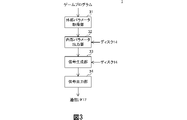
- FIG. 3 is a block diagram showing a configuration of a signal generation device according to an embodiment.
- FIG. 4 is a diagram for explaining an external parameter according to an embodiment.
- FIG. 5 is a diagram for explaining an example of the conversion process to the internal parameter according to the embodiment.
- FIG. 6 is a diagram for explaining an example of the conversion process to the internal parameter according to the embodiment.
- FIG. 7 is a diagram for explaining an example of a waveform signal generation process according to an embodiment.
- FIG. 8 is a diagram for explaining a flow of processing by the signal generator according to the embodiment.
- FIG. 9 is a diagram showing an outline of the system according to the modified example.
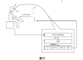
- FIG. 10 is a diagram showing an outline of a system according to a modified example.
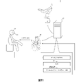
- FIG. 11 is a diagram showing an outline of a system according to
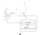
- FIG. 1 is a diagram showing an outline of a game system according to the present embodiment.
- the game system 3 mainly includes a computer 11, a display monitor 20, and a controller 21 (object).
- the computer 11 executes, for example, a game program, and displays the virtual reality developed by the game program on the display monitor 20.
- User 6 is, for example, the creator of a game program or a player of a game.
- the user 6 recognizes the situation of the character in the virtual reality displayed on the display monitor 20, and operates the controller 21 so as to give the character a movement according to the situation.
- the computer 11 executes the game program according to the operation content performed on the controller 21.
- the computer 11 presents the "force sense”, “pressure sense”, and “tactile sense” by haptics to at least one user 6 (hereinafter, may be referred to as haptics presentation).
- the "force sense” is, for example, the feeling when being pulled or pushed, and the feeling when being pressed tightly or popping.
- the "pressure sensation” is a feeling of contact, for example, when the object is in contact with the object, or when the object is felt to be firm or soft.
- the "tactile sensation” is, for example, the tactile sensation of the surface of an object, or the tactile sensation and roughness of the surface of an object such as the degree of unevenness.
- the software and hardware hierarchy in the computer 11 is composed of an application layer game program, an intermediate layer SDK (Software Development Kit), a system and a game engine, and a physical layer HW (Hardware).
- SDK includes, for example, plug-ins or authoring tools and middleware.
- the middleware includes a program (hereinafter, may be referred to as a target program) that vibrates the controller 21 so as to give the user 6 at least one of "force sense", "pressure sense", and "tactile sense”.
- a target program a program that vibrates the controller 21 so as to give the user 6 at least one of "force sense”, "pressure sense", and "tactile sense”.
- the game program calls the target program according to the API (Application Programming Interface).
- the game program passes, for example, event information indicating the type of event and the start time of the event to the target program.
- the type of event is specified, for example, by an ID.
- Certain events are, for example, in virtual reality, where an external force of pulling or pushing is applied to the character, the character shoots a gun, the character is hit, and the character dances to music. And so on.
- the target program generates a waveform signal for presenting sensory haptics according to the type of event indicated by the event information, based on the event information.
- the target program transmits the generated waveform signal to the controller 21 through the game engine, operating system, and hardware.
- the controller 21 vibrates based on the waveform signal. For example, by holding the vibrating controller 21 by hand, the user 6 recognizes the situation of the character in virtual reality not only by sight and hearing but also by at least one of "force sense”, “pressure sense” and “tactile sense”. can do.
- FIG. 2 is a diagram showing a hardware configuration of a game system according to this embodiment.
- the game system 3 includes a computer 11, a speaker 19, a display monitor 20, and a controller 21.
- the computer 11 includes a CPU (Central Processing Unit) 12, a memory 13, a disk 14, an audio interface (I / F) 15, a GPU (Graphics Processing Unit) 16, a communication interface (I / F) 17, and the like. Includes bus 18.
- the controller 21 includes an MCU (MicroControllerUnit) 22, a communication interface (I / F) 23, a haptics output drive 24, a haptics element 25, a sensor input drive 26, and a sensor element 27.
- MCU MicroControllerUnit
- the CPU 12, the memory 13, the disk 14, the audio interface 15, the GPU 16, and the communication interface 17 are connected via the bus 18 so that data can be transmitted and received to each other.
- the disk 14 is a non-volatile storage device such as an HDD (Hard Disk Drive) or SSD (Solid State Drive) capable of reading and writing, and a game program and a program (code) such as an SDK are stored.
- the disk 14 is not limited to the HDD and SSD, and may be a memory card, a read-only CD-ROM (Compact Disc Read Only Memory), a DVD-ROM (Digital Versatile Disc-Read Only Memory), or the like. good.
- programs such as the target program can be installed from the outside. Further, a program such as a target program is distributed in a state of being stored in a storage medium readable by a computer 11 such as a disk 14. The program such as the target program may be distributed on the Internet connected via the communication interface.
- the memory 13 is a volatile storage device such as a DRAM (Dynamic Random Access Memory).
- the communication interface 17 transmits and receives various data to and from the communication interface 23 in the controller 21. This communication may be carried out either by wire or wirelessly, and any communication protocol may be used as long as communication with each other can be carried out.
- the communication interface 17 transmits various data to the controller 21 according to the instruction from the CPU 12. Further, the communication interface 17 receives various data transmitted from the controller 21 and outputs the received data to the CPU 12.
- the CPU 12 transfers the program stored in the disk 14 and the data necessary for executing the program to the memory 13.
- the CPU 12 reads processing instructions and data necessary for executing the program from the memory 13, and executes arithmetic processing according to the contents of the processing instructions. At this time, the CPU 12 may newly generate data necessary for executing the program and store it in the memory 13.
- the CPU 12 is not limited to the configuration in which programs and data are acquired from the disk 14, but may be configured to acquire programs and data from a server or the like via the Internet.
- the CPU 12 receives the operation content for the controller 21 of the user 6 and executes a processing instruction according to the operation content to give a movement to the character in the virtual reality. At this time, the CPU 12 performs processing for presenting haptics, displaying video, and outputting audio according to the situation of the character in virtual reality.
- the CPU 12 is a waveform signal for presenting haptics of the force sensation felt when the external force is applied. To generate.
- the CPU 12 generates a waveform signal for presenting haptics of a reactionary feeling that is felt when a character shoots a gun, for example, in virtual reality.
- the CPU 12 generates a waveform signal for presenting haptics of a feeling of impact when the character is hit, for example, in virtual reality.
- the CPU 12 generates a waveform signal for presenting haptics of a dynamic feeling for musical beats and rhythms when a character is dancing to music, for example, in virtual reality.
- the CPU 12 generates haptic information by digitally encoding the generated waveform signal, and transmits the generated haptic information to the controller 21 via the communication interface 17.
- the CPU 12 generates screen information necessary for displaying images such as characters and backgrounds moving in virtual reality, and outputs the generated screen information to the GPU 16.
- the GPU 16 receives screen information from the CPU 12, for example, performs rendering or the like based on the screen information, and generates a digital video signal including a video such as 3D graphics.
- the GPU 16 transmits the generated digital video signal to the display monitor 20 to display 3D graphics and the like on the display monitor 20.
- the CPU 12 generates voice information indicating voice according to the environment, movement, situation, etc. of the character in virtual reality, and outputs the generated voice information to the audio interface 15.
- the audio interface 15 receives voice information from the CPU 12 and performs rendering or the like based on the received voice information to generate a voice signal.
- the audio interface 15 outputs the voice from the speaker 19 by transmitting the generated voice signal to the speaker 19.
- the haptics element 25 in the controller 21 is a vibration actuator that converts an electric signal into mechanical vibration, for example, a voice coil actuator having a wide frequency band for vibration relaxation.
- the haptic element 25 may be an eccentric motor, a linear resonance actuator, an electromagnetic actuator, a piezoelectric actuator, an ultrasonic actuator, an electrostatic actuator, a polymer actuator, or the like.
- the MCU 22 controls the haptics output drive 24 and the sensor input drive 26. Specifically, for example, when the MCU 22 receives power supply, it reads out a program stored in a ROM (not shown) and executes arithmetic processing according to the contents of the program.
- the MCU 22 when the MCU 22 receives the haptics information from the computer 11 via the communication interface 23, the MCU 22 controls the haptics output drive 24 based on the received haptics information, and the haptics element 25 presents the haptics.
- the MCU 22 outputs haptic information to the haptic output drive 24.
- the haptics output drive 24 receives haptics information from the MCU 22, and based on the received haptics information, generates an electric signal corresponding to the waveform signal, which is an analog electric signal capable of driving the haptics element 25, and haptics. Output to element 25. As a result, the haptics element 25 vibrates based on the electric signal, and the haptics are presented.
- the sensor element 27 detects the movement of an operation unit that receives an operation of the user 6, such as a joystick and a button provided on the controller 21, and outputs an analog electric signal indicating the detection result to the sensor input drive 26.
- the sensor input drive 26 operates, for example, under the control of the MCU 22, supplies electric power required for driving to the sensor element 27, receives an electric signal from the sensor element 27, and converts the received electric signal into a digital signal. ..
- the sensor input drive 26 outputs the converted digital signal to the MCU 22.
- the MCU 22 Based on the digital signal received from the sensor input drive 26, the MCU 22 generates operation information indicating the operation content for the controller 21 of the user 6 and transmits the operation information to the computer 11 via the communication interface 23.
- FIG. 3 is a block diagram showing a configuration of a signal generation device according to the present embodiment.
- the signal generation device 1 is realized, for example, by having the CPU 12 in the computer 11 execute a signal generation program which is an example of the target program.
- the signal generation device 1 includes an external parameter acquisition unit 31, an internal parameter output unit 32, a signal generation unit 33, and a signal output unit 34 as functional blocks.
- the external parameter acquisition unit 31 vibrates the controller 21 (haptics element 25) when a specific event occurs in a character in virtual reality, and acquires external parameters from the game program for presenting a predetermined haptics. do.
- External parameters include parameters that indicate the sensory (or psychological) characteristics of the perception that the user receives (eg, holding the controller 21) by presenting haptics.
- Sensory properties include, for example, the texture perceived by the user by presenting haptics.
- the external parameter includes a parameter indicating a characteristic indicating what kind of characteristic the particle has. That is, the external parameters include parameters relating to virtual particles in the sense of touch presented to the user of the controller 21 (object) by vibration.
- FIG. 4 shows an example of an external parameter showing the characteristics of the material feeling of particles in haptic presentation (for example, tactile sensation) as a sensory characteristic.
- the external parameters include a parameter that specifies "the degree of particle size", a parameter that specifies "the shape of particles”, and “the degree of variation in particles” as parameters indicating the characteristics of the texture. Includes parameters that specify. For each of these external parameters, for example, a value from 0 to 1.0 is set. The parameter that specifies the "degree of particle size" indicates that the smaller the value, the finer the particles, and the larger the value, the coarser the particles.
- the parameter for specifying the "particle shape” indicates that the smaller the value, the rounder the shape of the particle, and the larger the value, the sharper the shape of the particle.
- the parameter that specifies the "degree of variation in particles” indicates that the smaller the value, the more uniform the size and shape of the particles, and the larger the value, the more irregular the size and shape of the particles.
- the controller 21 when the "degree of particle size” is set to 0.1, the “shape of particles” is set to 0.8, and the “degree of variation of particles” is set to 0.4 as external parameters, the controller 21 The haptics presentation of the rough feeling is performed through. Further, as external parameters, for example, when “degree of particle size” is set to 0.8, “shape of particles” is set to 0.5, and “degree of variation of particles” is set to 0.7. A rugged haptics presentation is performed.
- the external parameters acquired by the external parameter acquisition unit 31 include three parameters in which values of 0 to 1.0 are set, respectively. With the combination of the three external parameters that can be changed in multiple stages in this way, many types of haptics can be presented. As a result, it is possible to select a more appropriate type of haptic presentation from more options than before, which improves the sense of presence. Similarly, the expression of tactile sensation, which was difficult to express in the past, becomes easier, and the available scenes increase.
- the external parameters showing the sensory characteristics shown in FIG. 4 are merely examples, and the external parameters may include other parameters or may not include any one or all of the above three parameters. good. External parameters may include, for example, parameters that indicate the physical characteristics of vibration (different from the sensory characteristics).
- the signal generation unit 33 described later After the external parameter acquisition unit 31 acquires the external parameter, the signal generation unit 33 described later generates a signal so that the haptics of the same characteristic is presented for a predetermined period or until the acquisition of the next external parameter.
- haptics with different characteristics may be presented over time.
- the external parameter acquisition unit 31 acquires an external parameter and a parameter indicating the execution start timing of the haptics presentation corresponding to the external parameter as a set.
- the internal parameter output unit 32 or the signal generation unit 33 which will be described later, so that when the external parameter acquisition unit 31 acquires a plurality of sets of the parameters, the change in the characteristics of the haptic presentation becomes smooth between the execution start timings.
- the characteristics of the haptic presentation may be complemented.
- the external parameters are stored in the game program of the game content in the game system 3 shown in FIG.
- a waveform signal for vibration of the controller 21 according to a specified external parameter is generated by a processing unit having the same function as the signal generation unit 33 described later, and is used in a game program. May be stored.
- the game designer or game developer specifies these external parameters to design the haptic presentation (eg, tactile presentation), and the external parameters or waveform signals are stored in the game program.
- GUI elements such as, for example, slide bars (eg, three slide bars corresponding to each of the above external parameters). May be good.
- the external parameters may be specified using the GUI provided in the form of a palette following the three primary colors of vision.
- the internal parameter output unit 32 outputs the internal parameter based on the external parameter acquired by the external parameter acquisition unit 31.
- Internal parameters are parameters that indicate the physical characteristics of vibration.
- the internal parameter is a parameter indicating a physical quantity corresponding to the generation of the waveform signal by the signal generation unit 33 described later.
- the internal parameters are used as coefficients for the waveform signal generation process by the signal generation unit 33, which will be described later.
- the internal parameter output unit 32 is a processing unit that converts an external parameter including a parameter indicating a sensory characteristic into a parameter indicating a physical quantity corresponding to the generation of a waveform signal.
- the information (eg, coefficients) used to process the conversion may be obtained from disk 14.
- the process of outputting the internal parameter from the external parameter by the internal parameter output unit 32 (hereinafter, also referred to as "conversion process") is executed by using an arbitrary process.
- conversion process for the conversion process by the internal parameter output unit 32, for example, an affine transformation specified to output the internal parameter from the external parameter may be used.
- the coefficients required for the conversion process may be determined by statistical methods or machine learning. For example, the coefficients may be determined based on the relationship between the external and internal parameters derived by statistical methods or machine learning.
- FIG. 5 shows an equation for converting external parameters (x1, x2, x3) into internal parameters (y1, y2, y3, y4, y5, y6, y7, y8, y9, y10, y11, y12) by affine transformation.
- the coefficients 1 and 2 are used as the coefficients.
- the number of internal parameters (12) is larger than the number of external parameters (3). In this way, by outputting a larger number of internal parameters than the number of external parameters, it is possible to generate more types of waveform signals by the processing of the signal generation unit 33 described later (that is, more types). Haptics can be presented).
- the number of internal parameters output by the internal parameter output unit 32 may be the same as the number of input external parameters, or may be smaller than the number of external parameters.
- the number of internal parameters and the number of external parameters can be set arbitrarily. The same applies to the examples described later.
- AI artificial intelligence
- the internal parameter output unit 32 may output an internal parameter from the external parameter by using a neural network model (learned model) that has learned the correlation between the external parameter and the internal parameter.
- the trained neural network model is used to set the external parameters (x1, x2, x3) to the internal parameters (y1, y2, y3, y4, y5, y6, y7, y8, y9, y10).
- Y11, y12 are conceptually shown.
- the conversion process by the internal parameter output unit 32 may use a statistical method, artificial intelligence (for example, machine learning or deep learning), or affine transformation. Further, the conversion process by the internal parameter output unit 32 may use at least a part of statistical methods, artificial intelligence, or affine transformation in combination.
- the signal generation unit 33 generates a waveform signal for generating vibration in the object based on the external parameter acquired by the external parameter acquisition unit 31. Specifically, the signal generation unit 33 generates a waveform signal based on the internal parameters output by the internal parameter output unit 32 with the external parameters acquired by the external parameter acquisition unit 31 as an input. Therefore, the generated waveform signal is based on external parameters.
- the signal generation unit 33 performs signal processing using, for example, the internal parameter output by the internal parameter output unit 32 as a coefficient, and generates a waveform signal. The information used for the signal processing is obtained from the disk 14.
- FIG. 7 shows an equation for generating a waveform signal using a sine wave.
- the internal parameters output by the internal parameter output unit 32 (for example, the internal parameters described with reference to FIGS. 5 or 6) are set in y1 to y12.
- a waveform signal is generated by an operation using the equation.
- Various frequency filters, limiter processing, and the like may be introduced in the processing of generating the waveform signal by the signal generation unit 33.
- the cutoff frequency is a simple internal parameter.
- the limit threshold is a simple internal parameter. In either case, internal parameters are used as physical quantity parameters suitable for signal processing.
- the signal output unit 34 generates haptic information by digitally encoding the waveform signal generated by the signal generation unit 33, and transmits the generated haptic information to the controller 21 via the communication interface 17. ..
- the signal generation device 1 generates vibration in the object based on the external parameter acquisition unit 31 that acquires the external parameter including the parameter indicating the sensory characteristic and the acquired external parameter.
- a signal generation unit 33 for generating a waveform signal for making the signal is provided.
- the external parameter is a characteristic quantity that represents the characteristics of the psychological particles when the material to be expressed as a tactile sensation is considered psychologically, for example, assuming that the material is composed of particles. Is. That is, since the external parameter has a sensory meaning, the psychological characteristic set as the external parameter matches the psychological characteristic perceived by the user by presenting the haptics. This makes it easier for game designers and game developers to intuitively set external parameters, improving convenience. In addition, the tactile sensation of the material desired by game designers and game developers can be realized, which improves satisfaction.
- the number of internal parameters output by the internal parameter output unit 32 and used by the signal generation unit 33 may be larger than the number of external parameters acquired by the external parameter acquisition unit 31. can.
- the internal parameter output unit 32 outputs a larger number of internal parameters than the number of external parameters, it is possible to present haptics with a richer tactile expression.
- the internal parameter output unit 32 outputs a larger number of internal parameters than the number of external parameters, it is possible to present haptics with a richer tactile expression with a smaller number of external parameters.
- the time and effort of the game designer and the game developer can be saved, and the convenience is improved.
- enabling haptics to be presented with abundant tactile expressions with a smaller number of external parameters leads to a reduction in the communication load due to the transmission of the external parameters and a reduction in the storage capacity of the external parameters.
- the signal generation device 1 waits until it receives an instruction for waveform signal generation from the game program (No in step S102). For example, when a specific event occurs in a character in virtual reality, the signal generation device 1 causes the controller 21 (haptics element 25) to vibrate and gives an API from a game program to give an instruction for presenting a predetermined haptics. Accept via (Application Programming Interface). In such a case, the signal generation device 1 determines that the instruction for generating the waveform signal has been received (Yes in step S102). If it is determined that the instruction for generating the waveform signal has been received, the process proceeds to step S104.
- the controller 21 haptics element 25
- the signal generation device 1 determines that the instruction for generating the waveform signal has been received (Yes in step S102). If it is determined that the instruction for generating the waveform signal has been received, the process proceeds to step S104.
- step S104 the signal generation device 1 acquires an external parameter for presenting a predetermined haptics included in the instruction for generating a waveform signal.
- External parameters include, as described above, parameters that indicate the sensory (or psychological) characteristics of the perception that the user receives from the haptic presentation.
- step S106 the signal generator 1 outputs an internal parameter based on the external parameter acquired in step S104.
- the internal parameter is a parameter indicating the physical characteristics of vibration.
- the process of outputting the internal parameters based on the external parameters may use, for example, a statistical method, artificial intelligence (for example, machine learning or deep learning), or an affine transformation.
- step S108 the signal generation device 1 generates a waveform signal for generating vibration in the object based on the internal parameters output in step S106. For example, as described above, the signal generation device 1 performs signal processing using the internal parameter output in step S106 as a coefficient to generate a waveform signal.
- step S110 the signal generation device 1 generates haptic information by digitally encoding the waveform signal generated in step S108, and transmits the generated haptic information to the controller 21 via the communication interface 17. After that, the process proceeds to step S102.
- the signal generation device 1 of the present embodiment has described a configuration for generating a waveform signal that causes the controller 21 to generate vibration in response to an event in virtual reality, but the present invention is not limited to this.
- the signal generation device 1 when an operation target such as a construction machine, a vehicle, or an airplane is remotely operated by a controller, the signal generation device 1 generates a waveform signal that causes the controller to generate vibration according to an actual event in the operation target. It may be a configuration.
- the signal generation device 1 acquires an external parameter including a parameter indicating a sensory characteristic, and obtains a waveform signal for generating vibration in an object based on the acquired external parameter.
- the external parameter is a characteristic quantity that represents the characteristics of the psychological particles when the material to be expressed as a tactile sensation is considered psychologically, for example, assuming that the material is composed of particles. Is. That is, since the external parameter has a sensory meaning, the psychological characteristic set as the external parameter matches the psychological characteristic perceived by the user by presenting the haptics. This makes it easier for game designers and game developers to intuitively set external parameters, improving convenience. In addition, the tactile sensation of the material desired by game designers and game developers can be realized, which improves satisfaction.
- a system is configured in which at least a part of the computer 11, the display monitor 20, and the controller 21 included in the game system 3 is replaced with another device such as a tablet device, a stylus, or a head-mounted display. be able to.
- the system 4 mainly includes a tablet terminal 41 and a stylus 51.
- the tablet terminal 41 has the same configuration as the computer 11 and the display monitor 20 in the game system 3.
- the tablet terminal 41 has, for example, a plate-shaped housing, and a display unit made of a liquid crystal display or the like is provided on one surface of the housing.
- the display unit is composed of, for example, a touch panel type.
- the tablet terminal 41 can be operated by moving the stylus 51 or the like in contact with the display unit.
- the stylus 51 presents the user 6 with various haptics.
- the stylus 51 has the same configuration as the controller 21 in the game system 3.
- the stylus 51 is a pen-shaped pointing device.
- Design or drawing software such as paint software, illustration software, CAD software, or 3DCG software is installed in the tablet terminal 41, and the user 6 grips the stylus 51 and holds the tip of the stylus 51 into a tablet.
- Various illustrations can be drawn or designed by contacting the display unit of the terminal 41. For example, the developer user 6 uses the system 4 to develop an application, and the designer user 6 uses the system 4 for design.
- the system 5 mainly includes a stylus 51 and a head-mounted display 61.
- the stylus 51 and the head-mounted display 61 are configured to be able to communicate with each other.
- the stylus 51 is a pen-shaped pointing device having the same configuration as the controller 21 in the game system 3.
- the head-mounted display 61 has the same configuration as the computer 11 and the display monitor 20 in the game system 3.
- the head-mounted display 61 is a display device configured to be mounted on the head of the user 6.
- the stylus 51 presents various haptics to the user 6.
- the user 6 can use the system 5 as a paint tool for drawing in the virtual space.
- the developer user 6 uses the system 5 to develop an application, and the designer user 6 uses the system 5 for design.
- the stylus 51 can change the perception presented to the user 6 in order to feel "what the user 6 is drawing” by presenting various haptics to the user 6.
- the stylus 51 can present the user 6 with a smooth sensation as if writing an illustration or the like on paper, or a sensation of friction as if writing on a campus by haptics.
- the stylus 51 can change the perception presented to the user 6 in order to feel "what the user 6 is drawing” by presenting various haptics to the user 6.
- the stylus 51 can present the user 6 with a hard sensation as if writing with a ballpoint pen or a soft sensation as if writing with a brush by haptics.
- User 6 can use the system 5 as CAD software or 3DCG software.
- the stylus 51 can change the perception presented to the user 6 so as to feel the virtual texture of the object designed by the user 6. .
- the stylus 51 can present the user 6 with the sensation of an object having an uneven surface by haptics.
- the stylus 51 can present the user 6 with a haptic feeling when he / she touches a virtual object being designed or does not come into contact with the object.
- the system 7 includes a head-mounted display 61, a computer 91, a robot 71, and a controller 81.
- the controller 81 has the same configuration as the controller 21, and is configured as, for example, a joystick type controller.
- the computer 91 has the same configuration as the computer 11, and is configured to be able to communicate with the head-mounted display 61, the robot 71, and the controller 81.
- the computer 91 controls the operation of the robot 71 according to, for example, the control signal received from the controller 81.
- the robot 71 is, for example, an arm-type robot, but may be a device that performs some operation such as a vehicle, a construction machine, or a drone.
- the robot 71 may be physically present at a remote location or in the vicinity, or may be virtually present.
- the user 6 who is a developer uses the system 7 to create a program.
- a control signal may be transmitted from the controller 81 to the computer 91, and a program for the operation of the robot 71 may be created.
- the created program, image information showing the operation of the robot 71, or the like may be transmitted from the computer 91 to the head-mounted display 61 and displayed on the display unit of the head-mounted display 61.
- the user 6 who is a pilot uses the system 7 to control the robot 71, for example.
- a control signal may be transmitted from the controller 81 to the computer 91 to control the operation of the robot 71.
- the controller 81 can present the user 6 with a sense of the road surface condition (for example, unevenness) on which the robot 71, which is a vehicle at a remote location, moves by presenting haptics.
- a sense of the road surface condition for example, unevenness
- the controller 81 gives the user 6 a sense of the situation of the place where the drone robot 71 flies (for example, a feeling of air resistance, a tail wind, or a head wind), or a feeling that the robot 71 touches something. Can be presented.
- the controller 81 presents to the user 6 the feeling of the road surface condition (for example, unevenness) on which the robot 71, which is a construction machine in a remote place, moves, or the feeling that the robot 71 touches something, by presenting haptics. be able to.
- the controller 81 touches or touches the material feeling (for example, unevenness feeling, soft or hard feeling) of the object touched or gripped by the robot 71 which is an end gripper (arm robot) by the presentation of haptics.
- the feeling of disappearance can be presented to the user 6.
Landscapes
- Engineering & Computer Science (AREA)
- Multimedia (AREA)
- General Engineering & Computer Science (AREA)
- Human Computer Interaction (AREA)
- Theoretical Computer Science (AREA)
- Physics & Mathematics (AREA)
- General Physics & Mathematics (AREA)
- User Interface Of Digital Computer (AREA)
Abstract
触覚により与えたい心理的な印象に、より近い印象を与える触覚を提示することに関する技術を提供する。信号生成装置は、感覚的な特性を示すパラメータを含む外部パラメータを取得することと、対象物に振動を発生させるために、前記外部パラメータに基づく波形信号を生成することとを実行する。
Description
本発明は、信号生成装置、信号生成方法及び信号生成プログラムに関する。
振動の生成により触覚を提示する装置が知られている。特許文献1には、操作体に与える触覚を再現するための触覚情報を作成して記憶し、ユーザによる装置に対する入力操作時に、当該触覚情報を使用してユーザの指に触覚を与える技術が開示されている。特許文献2には、振動の波形パターンや振動の周波数の制御によって、感覚量を提示する装置に関する技術が開示されている。
従来技術においては、触覚により与えたい心理的な印象と、振動によりユーザに提示される触覚の実際の印象とを近づけることが困難であった。
本発明はこのような事情に鑑みてなされたものであり、触覚により与えたい心理的な印象に、より近い印象を与える触覚を提示することに関する技術を提供することを目的とする。
本発明の一態様に係る信号生成装置は、感覚的な特性を示すパラメータを含む外部パラメータを取得する取得部と、対象物に振動を発生させるために、外部パラメータに基づく波形信号を生成する生成部とを備える。
本発明の一態様に係る信号生成方法は、感覚的な特性を示すパラメータを含む外部パラメータを取得することと、対象物に振動を発生させるために、外部パラメータに基づく波形信号を生成することとを含む。
本発明の一態様に係る信号生成プログラムは、感覚的な特性を示すパラメータを含む外部パラメータを取得することと、対象物に振動を発生させるために、外部パラメータに基づく波形信号を生成することとをコンピュータに実行させる。
本発明によれば、触覚により与えたい心理的な印象に、より近い印象を与える触覚を提示することに関する技術を提供することができる。
以下、本発明の実施の形態について、図面を参照しつつ詳細に説明する。なお、同一の要素には同一の符号を付し、重複する説明を極力省略する。
本実施形態に係るゲームシステムについて説明する。図1は、本実施形態に係るゲームシステムの概略を示す図である。図1に示すように、ゲームシステム3は、コンピュータ11と、ディスプレイモニタ20と、コントローラ21(対象物)と、を主に備える。
コンピュータ11は、例えば、ゲームプログラムを実行し、ゲームプログラムが展開する仮想現実をディスプレイモニタ20に表示する。ユーザ6は、例えば、ゲームプログラムの作成者またはゲームのプレーヤである。ユーザ6は、例えば、ディスプレイモニタ20に映し出された仮想現実におけるキャラクターの状況を認識し、その状況に応じてキャラクターに動きを与えるようにコントローラ21を操作する。コンピュータ11は、コントローラ21に対して行われた操作内容に応じてゲームプログラムを実行する。
また、コンピュータ11は、ハプティクスによる「力覚」、「圧覚」及び「触覚」の少なくとも1つのユーザ6への提示(以下、ハプティクス提示と称することがある。)を行う。ここで、「力覚」は、例えば、引っ張られたり、押されたりされたときの感触及びギューと押さえたり、プッチンと弾けたときの手ごたえ感である。「圧覚」は、例えば、物体に接触したとき、または物体の堅さもしくは柔らかさを感じたときなどの接触感である。「触覚」は、例えば、物体の表面の触り心地、または物体の表面の凹凸度合いなどの触感及び粗さ感である。
コンピュータ11におけるソフトウェア及びハードウェアの階層は、アプリケーション層のゲームプログラム、中間層のSDK(Software Development Kit)、システム及びゲームエンジン、ならびに物理層のHW(Hardware)によって構成される。
SDKは、例えば、プラグインまたはオーサリングツールと、ミドルウェアと、を含む。ミドルウェアには、「力覚」、「圧覚」及び「触覚」の少なくとも1つをユーザ6に与えるようにコントローラ21を振動させるプログラム(以下、対象プログラムと称することがある。)が含まれる。ゲームプログラムは、例えば、キャラクターに特定のイベントが発生すると、API(Application Programming Interface)に従って対象プログラムを呼び出す。このとき、ゲームプログラムは、例えば、イベントの種類及び当該イベントの開始時刻を示すイベント情報を対象プログラムに渡す。イベントの種類は、例えばIDによって特定される。
特定のイベントは、例えば、仮想現実内において、引っ張ったり押したりする外力がキャラクターに加わったこと、キャラクターが銃を撃ったこと、キャラクターが打撃を受けたこと、及びキャラクターが音楽に合わせて踊っていることなどである。
対象プログラムは、イベント情報に基づいて、イベント情報の示すイベントの種類に応じた感覚のハプティクス提示をするための波形信号を生成する。対象プログラムは、生成した波形信号を、ゲームエンジン、オペレーティングシステム及びハードウェアを通じてコントローラ21へ送信する。
コントローラ21は、波形信号に基づいて振動する。ユーザ6は、例えば、振動するコントローラ21を手で持つことで、仮想現実におけるキャラクターの状況を、視覚及び聴覚だけでなく、「力覚」、「圧覚」及び「触覚」の少なくとも1つによって認識することができる。
図2は、本実施形態に係るゲームシステムのハードウェア構成を示す図である。図2に示すように、ゲームシステム3は、コンピュータ11と、スピーカ19と、ディスプレイモニタ20と、コントローラ21と、を備える。コンピュータ11は、CPU(Central Processing Unit)12と、メモリ13と、ディスク14と、オーディオインターフェース(I/F)15と、GPU(Graphics Processing Unit)16と、通信インターフェース(I/F)17と、バス18と、を含む。コントローラ21は、MCU(Micro Controller Unit)22と、通信インターフェース(I/F)23と、ハプティクス出力駆動器24と、ハプティクス素子25と、センサ入力駆動器26と、センサ素子27と、を含む。
コンピュータ11では、CPU12、メモリ13、ディスク14、オーディオインターフェース15、GPU16及び通信インターフェース17は、互いにデータの送受信が可能なようにバス18を通じて接続される。
本実施形態では、ディスク14は、HDD(Hard Disk Drive)またはSSD(Solid State Drive)などの読み書きが可能な不揮発性の記憶装置であり、ゲームプログラム及びSDKなどのプログラム(コード)が保存されている。なお、ディスク14は、HDD及びSSDに限定するものではなく、メモリーカードまたは読み込み専用のCD-ROM(Compact Disc Read Only Memory)若しくはDVD-ROM(Digital Versatile Disc-Read Only Memory)などであってもよい。また、対象プログラムなどのプログラムは、外部からインストールすることができる。また、対象プログラムなどのプログラムは、ディスク14のようなコンピュータ11によって読み取り可能な記憶媒体に格納された状態で流通する。なお、対象プログラムなどのプログラムは、通信インターフェースを経由して接続されたインターネット上で流通するものであってもよい。
メモリ13は、DRAM(Dynamic Random Access Memory)などの揮発性の記憶装置である。通信インターフェース17は、コントローラ21における通信インターフェース23と各種データの送受信を行う。この通信は、有線及び無線のいずれで実行されてもよく、互いの通信が実行できるのであれば、どのような通信プロトコルを用いてもよい。通信インターフェース17は、CPU12からの指示に従って各種データをコントローラ21へ送信する。また、通信インターフェース17は、コントローラ21から送信された各種データを受信し、受信したデータをCPU12へ出力する。
CPU12は、プログラムの実行時において、ディスク14に保存された当該プログラム及び当該プログラムの実行に必要なデータをメモリ13に転送する。CPU12は、プログラムの実行に必要な処理命令及びデータをメモリ13から読み出し、処理命令の内容に従って演算処理を実行する。このとき、CPU12は、プログラムの実行に必要なデータを新たに生成してメモリ13に保存する場合がある。なお、CPU12は、プログラム及びデータをディスク14から取得する構成に限らず、インターネットを経由してサーバなどから取得する構成であってもよい。
具体的には、CPU12は、例えば、ゲームプログラムの実行時において、ユーザ6のコントローラ21に対する操作内容を受けて、操作内容に応じた処理命令を実行し、仮想現実内のキャラクターに動きを与える。このとき、CPU12は、仮想現実内のキャラクターの状況に応じて、ハプティクス提示、映像表示及び音声出力を行うための処理を行う。
より具体的には、CPU12は、例えば、仮想現実内において、引っ張ったり押したりする外力がキャラクターに加わったときに、当該外力が加わったときに感じる力覚感のハプティクス提示をするための波形信号を生成する。
また、CPU12は、例えば、仮想現実内において、キャラクターが銃を撃ったときに、銃を撃ったときなどに感じる反動感のハプティクス提示をするための波形信号を生成する。
また、CPU12は、例えば、仮想現実内において、キャラクターが打撃を受けたときに、打撃を受けたときなどに感じる衝撃感のハプティクス提示をするための波形信号を生成する。
また、CPU12は、例えば、仮想現実内において、キャラクターが音楽に合わせて踊っているときに、音楽的なビートやリズムなどに対して感じる躍動感のハプティクス提示をするための波形信号を生成する。
CPU12は、生成した波形信号をデジタル符号化することによってハプティクス情報を生成し、生成したハプティクス情報を通信インターフェース17経由でコントローラ21へ送信する。
また、CPU12は、仮想現実内で動くキャラクター及び背景などの映像表示に必要な画面情報を生成し、生成した画面情報をGPU16へ出力する。GPU16は、例えば、CPU12から画面情報を受けて、画面情報に基づいてレンダリングなどを行い、3Dグラフィクスなどの映像を含むデジタル映像信号を生成する。GPU16は、生成したデジタル映像信号をディスプレイモニタ20へ送信することによって、ディスプレイモニタ20に3Dグラフィクスなどを表示させる。
また、CPU12は、仮想現実内のキャラクターの環境、動き及び状況などに応じた音声を示す音声情報を生成し、生成した音声情報をオーディオインターフェース15へ出力する。オーディオインターフェース15は、例えば、CPU12から音声情報を受けて、受けた音声情報に基づいてレンダリングなどを行い、音声信号を生成する。オーディオインターフェース15は、生成した音声信号をスピーカ19へ送信することによって、スピーカ19から音声を出力させる。
コントローラ21におけるハプティクス素子25は、電気信号を力学的な振動に変換する振動アクチュエータであり、例えば、振動緩和の周波数帯域が広いボイスコイルアクチュエータである。なお、ハプティクス素子25は、偏心モータ、リニア共振アクチュエータ、電磁アクチュエータ、圧電アクチュエータ、超音波アクチュエータ、静電アクチュエータまたは高分子アクチュエータなどであってもよい。
MCU22は、ハプティクス出力駆動器24及びセンサ入力駆動器26を制御する。具体的には、MCU22は、例えば、電源の供給を受けたときに、ROM(図示しない)に保存されたプログラムを読み出し、当該プログラムの内容に従って演算処理を実行する。
本実施形態では、MCU22は、例えば、コンピュータ11から通信インターフェース23経由でハプティクス情報を受信すると、受信したハプティクス情報に基づいてハプティクス出力駆動器24を制御し、ハプティクス素子25によってハプティクス提示を行う。
具体的には、MCU22は、ハプティクス情報をハプティクス出力駆動器24へ出力する。ハプティクス出力駆動器24は、MCU22からハプティクス情報を受けて、受けたハプティクス情報に基づいて、波形信号に応じた電気信号であって、ハプティクス素子25を駆動可能なアナログの電気信号を生成してハプティクス素子25へ出力する。これにより、ハプティクス素子25が電気信号に基づいて振動し、ハプティクス提示が行われる。
センサ素子27は、例えば、コントローラ21に設けられているジョイスティック及びボタンといったユーザ6の操作を受ける操作部の動きを検知し、検知結果を示すアナログの電気信号をセンサ入力駆動器26へ出力する。
センサ入力駆動器26は、例えば、MCU22の制御に従って動作し、駆動に必要な電力をセンサ素子27に供給するとともに、センサ素子27から電気信号を受けて、受けた電気信号をデジタル信号に変換する。センサ入力駆動器26は、変換したデジタル信号をMCU22へ出力する。MCU22は、センサ入力駆動器26から受けるデジタル信号に基づいて、ユーザ6のコントローラ21に対する操作内容を示す操作情報を生成して通信インターフェース23経由でコンピュータ11へ送信する。
[信号生成装置の構成]
図3は、本実施形態に係る信号生成装置の構成を示すブロック図である。信号生成装置1は、例えば、コンピュータ11におけるCPU12において、対象プログラムの一例である信号生成プログラムを実行させることによって実現されるものである。信号生成装置1は、機能ブロックとして、外部パラメータ取得部31、内部パラメータ出力部32、信号生成部33、及び信号出力部34を備える。
図3は、本実施形態に係る信号生成装置の構成を示すブロック図である。信号生成装置1は、例えば、コンピュータ11におけるCPU12において、対象プログラムの一例である信号生成プログラムを実行させることによって実現されるものである。信号生成装置1は、機能ブロックとして、外部パラメータ取得部31、内部パラメータ出力部32、信号生成部33、及び信号出力部34を備える。
外部パラメータ取得部31は、仮想現実内のキャラクターに特定のイベントが発生したときに、コントローラ21(ハプティクス素子25)に振動を生じさせ、所定のハプティクス提示を行うための外部パラメータをゲームプログラムから取得する。
外部パラメータは、ハプティクス提示により(例えば、コントローラ21を握持する)ユーザが受ける知覚の感覚的(又は心理感覚的)な特性を示すパラメータを含む。感覚的な特性は、例えば、ハプティクス提示によって、ユーザが知覚する材質感を含む。例えば、当該材質感が粒子によって構成される材質の感覚である場合、外部パラメータは、当該粒子がどのような特性を持っているかを表す特性を示すパラメータを含む。すなわち、外部パラメータは、コントローラ21(対象物)のユーザに振動により提示される触覚における仮想的な粒子に関するパラメータを含む。
図4に、感覚的な特性としてハプティクス提示(例えば、触覚)における粒子の材質感の特性を示す外部パラメータの例を示している。図4に示すように、外部パラメータは、材質感の特性を示すパラメータとして、「粒子の大きさの程度」を指定するパラメータ、「粒子の形状」を指定するパラメータ、及び「粒子のばらつきの程度」を指定するパラメータを含む。これらの外部パラメータのそれぞれには、例えば、0から1.0の値が設定される。「粒子の大きさの程度」を指定するパラメータは、値が小さいほど粒子が細かく、値が大きいほど粒子が粗いことを示す。「粒子の形状」を指定するパラメータは、値が小さいほど粒子の形状が丸く、値が大きいほど粒子の形状が鋭いことを示す。「粒子のばらつきの程度」を指定するパラメータは、値が小さいほど粒子の大きさ及び形状が均一で、値が大きいほど粒子の大きさ及び形状が不揃いであることを示す。
例えば、外部パラメータとして、「粒子の大きさの程度」が0.1、「粒子の形状」が0.8、及び「粒子のばらつきの程度」が0.4に設定されている場合、コントローラ21を介してざらざらした感覚のハプティクス提示が行われる。また、外部パラメータとして、例えば、「粒子の大きさの程度」が0.8、「粒子の形状」が0.5、及び「粒子のばらつきの程度」が0.7に設定されている場合、ごつごつした感覚のハプティクス提示が行われる。
図4の例において、外部パラメータ取得部31により取得される外部パラメータは、それぞれ0から1.0の値が設定される3つのパラメータを含む。このように多段階に変更可能な3つの外部パラメータの組合せにより、多くの種類のハプティクス提示を行うことができる。その結果、従来よりも多くの選択肢からより適切な種類のハプティクス提示を選ぶことができるため、臨場感の向上が得られる。同様に、従来では表現が困難であった触覚の表現が容易になり、利用可能シーンが増加する。
図4に示した感覚的な特性を示す外部パラメータは例に過ぎず、外部パラメータは、他のパラメータを含んでもよいし、上記3つのパラメータのうち、いずれか一つ又は全てを含まなくてもよい。外部パラメータは、例えば、(感覚的な特性とは異なる)振動の物理的特性を示すパラメータを含んでもよい。
外部パラメータ取得部31が外部パラメータを取得した後、同じ特性のハプティクス提示が所定期間、又は次の外部パラメータの取得まで行われるように、後述する信号生成部33により信号生成が行われる。変形例として、時間の経過とともに異なる特性のハプティクス提示が行われるようにしてもよい。この場合において、例えば、外部パラメータ取得部31は、外部パラメータと、当該外部パラメータに応じたハプティクス提示の実行開始タイミングを示すパラメータとをセットで取得する。外部パラメータ取得部31が、当該パラメータのセットを複数取得したときに、実行開始タイミング間でハプティクス提示の特性の変化が滑らかになるように、後述する内部パラメータ出力部32又は信号生成部33にて、ハプティクス提示の特性の補完が行われてもよい。
外部パラメータは、図1に示すゲームシステム3において、ゲームコンテンツのゲームプログラムに格納されている。または、ゲームコンテンツの開発の際に、指定された外部パラメータに応じたコントローラ21の振動のための波形信号を、後述する信号生成部33と同様の機能を有する処理部により生成し、ゲームプログラムに格納してもよい。いずれの場合においても、ゲームデザイナやゲーム開発者が、これらの外部パラメータを指定してハプティクス提示(例えば、触覚の提示)をデザインし、外部パラメータ又は波形信号がゲームプログラムに格納される。この場合において、ゲームデザイナやゲーム開発者が、例えばスライドバー(例えば、上記の外部パラメータのそれぞれに対応する3つのスライドバー)のようなGUI要素を使用して、外部パラメータを指定できるようにしてもよい。または、視覚の三原色に倣ってパレットの形で提供されたGUIを使用して外部パラメータを指定できるようにしてもよい。
図3の説明に戻り、内部パラメータ出力部32は、外部パラメータ取得部31が取得した外部パラメータに基づいて、内部パラメータを出力する。内部パラメータは、振動の物理的特性を示すパラメータである。換言すれば、内部パラメータは、後述する信号生成部33による波形信号の生成に即した物理量を示すパラメータである。例えば、内部パラメータは、後述する信号生成部33による波形信号の生成処理のための係数に使用される。すなわち、内部パラメータ出力部32は、感覚的な特性を示すパラメータを含む外部パラメータを、波形信号の生成に即した物理量を示すパラメータに変換する処理部である。当該変換の処理のために使用される情報(例えば、係数)は、ディスク14から取得されてもよい。
内部パラメータ出力部32により外部パラメータから内部パラメータを出力する処理(以下、「変換処理」とも称する。)は、任意の処理を使用して実行される。内部パラメータ出力部32による変換処理は、例えば、外部パラメータから内部パラメータを出力するように規定されたアフィン変換を使用してもよい。当該変換処理に必要とされる係数は、統計的手法又は機械学習によって決定されてもよい。例えば、統計的手法又は機械学習により導出される外部パラメータと内部パラメータとの間の関係に基づいて、係数を決定してもよい。
図5を参照して、変換処理にアフィン変換を使用する方法の例を説明する。図5は、アフィン変換により、外部パラメータ(x1、x2、x3)を内部パラメータ(y1、y2、y3、y4、y5、y6、y7、y8、y9、y10、y11、y12)に変換する式の例を示している。この例において、係数として、係数1及び係数2が使用されている。また、この例において、内部パラメータの数(12)は、外部パラメータの数(3)より多い。このように、外部パラメータの数より多い数の内部パラメータを出力することによって、後述する信号生成部33の処理により、より多くの種類の波形信号を生成することができる(すなわち、より多くの種類のハプティクス提示を行うことができる)。
なお、内部パラメータ出力部32により出力される内部パラメータの数は、入力される外部パラメータの数と同じであってもよいし、外部パラメータの数よりも少なくてもよい。内部パラメータの数及び外部パラメータの数は、任意に設定することができる。後述する例においても同様である。
内部パラメータ出力部32による変換処理は、ディープラーニングなどのAI(人工知能)を使用してもよい。例えば、内部パラメータ出力部32は、外部パラメータと内部パラメータとの間の相関関係を学習したニューラルネットワークモデル(学習済みモデル)を使用して、外部パラメータから内部パラメータを出力してもよい。
図6を参照して、ディープラーニングを使用する変換処理の例を示している。図6に示す例において、学習済みのニューラルネットワークモデルを使用して、外部パラメータ(x1、x2、x3)を内部パラメータ(y1、y2、y3、y4、y5、y6、y7、y8、y9、y10、y11、y12)に変換する処理が概念的に示されている。
以上のように、内部パラメータ出力部32による変換処理は、統計的手法、人工知能(例えば、機械学習、又はディープラーニング)、又はアフィン変換を使用してもよい。また、内部パラメータ出力部32による変換処理は、統計的手法、人工知能、又はアフィン変換のうち少なくとも一部を組み合わせて使用してもよい。
図3の説明に戻り、信号生成部33は、外部パラメータ取得部31が取得した外部パラメータに基づく、対象物に振動を発生させるための波形信号を生成する。詳細には、信号生成部33は、外部パラメータ取得部31が取得した外部パラメータを入力として内部パラメータ出力部32により出力された内部パラメータに基づいて、波形信号を生成する。従って、生成された波形信号は、外部パラメータに基づいている。信号生成部33は、例えば、内部パラメータ出力部32により出力された内部パラメータを係数として使用して信号処理を行い、波形信号の生成を行う。当該信号処理に使用される情報は、ディスク14から取得される。
図7を参照して、信号生成部33による波形信号の生成の処理の例を説明する。図7には、正弦波により波形信号を生成するための式が示されている。当該式中、y1からy12には、内部パラメータ出力部32により出力された内部パラメータ(例えば、図5又は図6を参照して説明された内部パラメータ)が設定される。当該式を使用した演算により、波形信号が生成される。
信号生成部33による波形信号の生成の処理には、各種の周波数フィルタやリミッタ処理などが導入されてもよい。フィルタ処理の場合、カットオフ周波数などが素朴な内部パラメータである。リミッタ処理の場合、リミット閾値が素朴な内部パラメータである。いずれの場合においても、信号処理に即した物理量パラメータとして、内部パラメータが使用される。
図3の説明に戻り、信号出力部34は、信号生成部33が生成した波形信号をデジタル符号化することによってハプティクス情報を生成し、生成したハプティクス情報を通信インターフェース17経由でコントローラ21へ送信する。
以上のように本実施形態に係る信号生成装置1は、感覚的な特性を示すパラメータを含む外部パラメータを取得する外部パラメータ取得部31と、取得された外部パラメータに基づく、対象物に振動を発生させるための波形信号を生成する信号生成部33とを備える。
外部パラメータは、触覚として表現したい材質を心理感覚的に考えたときに、例えば、その材質が粒子から構成されると想定して、その心理感覚的粒子がどのような特性をもっているかを表す特性量である。つまり、外部パラメータが感覚的な意味を持つため、外部パラメータとして設定された心理的な特性と、ハプティクス提示によりユーザが知覚する心理的な特性とが一致する。これにより、ゲームデザイナやゲーム開発者が外部パラメータを直感的に設定することが容易となり、利便性が向上する。また、ゲームデザイナやゲーム開発者が望む材質感の触覚を実現できるため、満足感が向上する。
また、本実施形態によれば、外部パラメータ取得部31により取得される外部パラメータの数よりも、内部パラメータ出力部32により出力され信号生成部33で使用される内部パラメータの数を多くすることができる。
一般的に、触覚表現を豊富に広げるためには、内部パラメータの数を多くする必要がある。すなわち、内部パラメータ出力部32は、外部パラメータの数よりも多くの数の内部パラメータを出力するため、より豊富な触覚表現でハプティクス提示を行うことを可能にする。換言すれば、本実施形態によれば、より少ない数の外部パラメータで、より豊富な触覚表現でハプティクス提示を行うことを可能にする。その結果、ゲームデザイナやゲーム開発者の手間が省け、利便性が向上する。また、より少ない数の外部パラメータでより豊富な触覚表現でハプティクス提示を可能とすることは、外部パラメータの送信による通信負荷の低減や、外部パラメータの記憶容量の削減にもつながる。
[信号生成処理のフロー]
図8を参照して、本実施形態に係る信号生成装置1がコントローラ21を振動させるための波形信号を出力するための処理フローの例を説明する。既に説明した処理については、ここでは簡単に説明する。図8に示される処理は、CPU12により制御される。
図8を参照して、本実施形態に係る信号生成装置1がコントローラ21を振動させるための波形信号を出力するための処理フローの例を説明する。既に説明した処理については、ここでは簡単に説明する。図8に示される処理は、CPU12により制御される。
図8に示すように、まず、信号生成装置1は、ゲームプログラムから波形信号生成の指示を受け付けるまで待機する(ステップS102のNo)。信号生成装置1は、例えば、仮想現実内のキャラクターに特定のイベントが発生したときに、コントローラ21(ハプティクス素子25)に振動を生じさせ、所定のハプティクス提示を行うための指示をゲームプログラムからAPI(Application Programming Interface)を介して受け付ける。このような場合において、信号生成装置1は、波形信号生成の指示を受け付けたと判断する(ステップS102のYes)。波形信号生成の指示を受け付けたと判断されると、処理は、ステップS104へ進む。
ステップS104において、信号生成装置1は、波形信号生成の指示に含まれる所定のハプティクス提示を行うための外部パラメータを取得する。外部パラメータは、前述のとおり、ハプティクス提示によりユーザが受ける知覚の感覚的(又は心理感覚的)な特性を示すパラメータを含む。
次に、ステップS106において、信号生成装置1は、ステップS104で取得された外部パラメータに基づいて、内部パラメータを出力する。内部パラメータは、前述のとおり、振動の物理的特性を示すパラメータである。外部パラメータに基づいて内部パラメータを出力する処理(変換処理)は、前述のとおり、例えば、統計的手法、人工知能(例えば、機械学習、又はディープラーニング)、又はアフィン変換を使用してもよい。
次に、ステップS108において、信号生成装置1は、ステップS106で出力された内部パラメータに基づいて、対象物に振動を発生させるための波形信号を生成する。例えば、前述のとおり、信号生成装置1は、ステップS106で出力された内部パラメータを係数として使用して信号処理を行い、波形信号の生成を行う。
次に、ステップS110において、信号生成装置1は、ステップS108で生成された波形信号をデジタル符号化することによってハプティクス情報を生成し、生成したハプティクス情報を通信インターフェース17経由でコントローラ21へ送信する。その後、処理はステップS102へ進む。
また、本実施形態の信号生成装置1は、仮想現実内におけるイベントに応じた振動をコントローラ21に発生させる波形信号を生成する構成について説明したが、これに限定するものではない。信号生成装置1は、例えば、建設機械、車両及び飛行機などの操作対象を遠隔からコントローラで操作する場合において、当該操作対象における現実のイベントに応じた振動を当該コントローラに発生させる波形信号を生成する構成であってもよい。
以上のように本実施形態に係る信号生成装置1は、感覚的な特性を示すパラメータを含む外部パラメータを取得し、取得された外部パラメータに基づく、対象物に振動を発生させるための波形信号を生成する。外部パラメータは、触覚として表現したい材質を心理感覚的に考えたときに、例えば、その材質が粒子から構成されると想定して、その心理感覚的粒子がどのような特性をもっているかを表す特性量である。つまり、外部パラメータが感覚的な意味を持つため、外部パラメータとして設定された心理的な特性と、ハプティクス提示によりユーザが知覚する心理的な特性とが一致する。これにより、ゲームデザイナやゲーム開発者が外部パラメータを直感的に設定することが容易となり、利便性が向上する。また、ゲームデザイナやゲーム開発者が望む材質感の触覚を実現できるため、満足感が向上する。
[変形例]
以上説明した各実施形態は、本発明の理解を容易にするためのものであり、本発明を限定して解釈するためのものではない。本発明は、その趣旨を逸脱することなく、変更/改良され得るとともに、本発明にはその等価物も含まれる。即ち、各実施形態に当業者が適宜設計変更を加えたものも、本発明の特徴を備えている限り、本発明の範囲に包含される。例えば、各実施形態が備える各要素及びその配置、材料、条件、形状、サイズなどは、例示したものに限定されるわけではなく適宜変更することができる。また、各実施形態は例示であり、異なる実施形態で示した構成の部分的な置換又は組み合わせが可能であることは言うまでもなく、これらも本発明の特徴を含む限り本発明の範囲に包含される。
以上説明した各実施形態は、本発明の理解を容易にするためのものであり、本発明を限定して解釈するためのものではない。本発明は、その趣旨を逸脱することなく、変更/改良され得るとともに、本発明にはその等価物も含まれる。即ち、各実施形態に当業者が適宜設計変更を加えたものも、本発明の特徴を備えている限り、本発明の範囲に包含される。例えば、各実施形態が備える各要素及びその配置、材料、条件、形状、サイズなどは、例示したものに限定されるわけではなく適宜変更することができる。また、各実施形態は例示であり、異なる実施形態で示した構成の部分的な置換又は組み合わせが可能であることは言うまでもなく、これらも本発明の特徴を含む限り本発明の範囲に包含される。
上記実施形態の変形例として、ゲームシステム3に含まれるコンピュータ11、ディスプレイモニタ20、及びコントローラ21の少なくとも一部をタブレット装置、スタイラス、又はヘッドマウントディスプレイなどの他の装置に置き換えたシステムを構成することができる。
図9を参照して、上記実施形態に係るゲームシステム3の変形例として、システム4を説明する。システム4は、タブレット端末41と、スタイラス51と、を主に備える。タブレット端末41は、ゲームシステム3におけるコンピュータ11及びディスプレイモニタ20と同様の構成を備える。タブレット端末41は、例えば、板状の筐体を有し、筐体の一つの面には、液晶などにより構成された表示部が設けられている。当該表示部は、例えば、タッチパネル式で構成される。当該表示部にスタイラス51などを接触させた状態で移動等させることにより、タブレット端末41に対する操作が可能である。スタイラス51は、ユーザ6に各種のハプティクスを提示する。
スタイラス51は、ゲームシステム3におけるコントローラ21と同様の構成を備える。スタイラス51は、ペン状のポインティングデバイスである。タブレット端末41には、例えば、ペイントソフトウェア、イラストソフトウェア、CADソフトウェア、又は3DCGソフトウェアなどのデザイン又は描画用のソフトウェアがインストールされており、ユーザ6は、スタイラス51を把持し、スタイラス51の先端をタブレット端末41の表示部に接触させ、各種のイラスト描画又はデザイン等を行うことができる。例えば、デベロッパであるユーザ6は、アプリを開発するためにシステム4を使用し、デザイナであるユーザ6は、デザインのためにシステム4を使用する。
次に、図10を参照して、ゲームシステム3の他の変形例として、システム5を説明する。システム5は、スタイラス51と、ヘッドマウントディスプレイ61とを主に備える。スタイラス51と、ヘッドマウントディスプレイ61は、互いに通信可能に構成されている。スタイラス51は、図9を参照して説明したように、ゲームシステム3におけるコントローラ21と同様の構成を備えるペン状のポインティングデバイスである。ヘッドマウントディスプレイ61は、ゲームシステム3におけるコンピュータ11及びディスプレイモニタ20と同様の構成を備える。ヘッドマウントディスプレイ61は、ユーザ6の頭部に装着可能に構成されたディスプレイ装置である。
スタイラス51は、ユーザ6に各種のハプティクスを提示する。ユーザ6は、仮想空間に描画を行うためのペイントツールとしてシステム5を使用することができる。例えば、デベロッパであるユーザ6は、アプリを開発するためにシステム5を使用し、デザイナであるユーザ6は、デザインのためにシステム5を使用する。
ユーザ6は、ペイントソフトソフトウェア又はイラストソフトウェアとしてシステム5を使用可能である。その場合において、スタイラス51は、ユーザ6に各種のハプティクスを提示することにより、ユーザ6がイラスト等を「何に描いているか」を感じるために、ユーザ6に提示する知覚を変えることができる。例えば、スタイラス51は、イラスト等を紙に書いているような滑らかな感覚、又はキャンパスに書いているような摩擦の感覚をハプティクスによりユーザ6に提示することが可能である。
また、スタイラス51は、ユーザ6に各種のハプティクスを提示することにより、ユーザ6がイラスト等を「何で描いているか」を感じるために、ユーザ6に提示する知覚を変えることができる。例えば、スタイラス51は、ボールペンで書いているような硬い感覚、又は筆で書いているような柔らかい感覚をハプティクスによりユーザ6に提示することが可能である。
ユーザ6は、CADソフトウェア、又は3DCGソフトウェアとしてシステム5を使用可能である。その場合において、スタイラス51は、ユーザ6に各種のハプティクスを提示することにより、ユーザ6がデザインしている物体の仮想的な材質感を感じるように、ユーザ6に提示する知覚を変えることができる。例えば、スタイラス51は、表面に凹凸がある物体の感覚をハプティクスによりユーザ6に提示することが可能である。また、スタイラス51は、デザインしている仮想的な物体に触れたり、当該物体に接触しなくなったときの感覚をハプティクスによりユーザ6に提示することが可能である。
次に、図11を参照して、ゲームシステム3の他の変形例として、システム7を説明する。システム7は、ヘッドマウントディスプレイ61と、コンピュータ91と、ロボット71と、コントローラ81とを備える。コントローラ81は、コントローラ21と同様の構成を備え、例えば、ジョイスティック型のコントローラとして構成される。コンピュータ91は、コンピュータ11と同様の構成を備え、また、ヘッドマウントディスプレイ61と、ロボット71と、コントローラ81と通信可能に構成されている。コンピュータ91は、例えば、コントローラ81から受信した制御信号に応じて、ロボット71の動作を制御する。ロボット71は、例えば、アーム型ロボットであるが、車両、建設機械、又はドローンなどの何らかの動作を行う装置であってもよい。ロボット71は、遠隔地又は近隣に物理的に存在するものであってもよいし、仮想的に存在するものであってもよい。
例えば、デベロッパであるユーザ6は、プログラムを作成するためにシステム7を使用する。詳細には、デベロッパであるユーザ6によるコントローラ81の操作に応じて、コントローラ81から制御信号がコンピュータ91に送信され、ロボット71の動作のためのプログラムが作成されてもよい。作成されたプログラム又はロボット71の動作を示す画像情報などが、コンピュータ91からヘッドマウントディスプレイ61に送信され、ヘッドマウントディスプレイ61の表示部に表示されてもよい。また、パイロットであるユーザ6は、例えば、ロボット71を操縦するためにシステム7を使用する。詳細には、パイロットであるユーザ6によるコントローラ81の操作に応じて、コントローラ81から制御信号がコンピュータ91に送信され、ロボット71の動作が制御されてもよい。
コントローラ81は、ハプティクス提示により、遠隔地にある車両であるロボット71が移動する路面の状況(例えば、凹凸)の感覚をユーザ6に提示することができる。コントローラ81は、ハプティクス提示により、ドローンであるロボット71が飛行する場所の状況(例えば、空気の抵抗感、追い風、又は向かい風など)の感覚、又はロボット71が何かに接触した感覚をユーザ6に提示することができる。
また、コントローラ81は、ハプティクス提示により、遠隔地にある建設機械であるロボット71が移動する路面の状況(例えば、凹凸)の感覚、又はロボット71が何かに接触した感覚をユーザ6に提示することができる。
コントローラ81は、ハプティクス提示により、エンドグリッパ(アームロボット)であるロボット71が触れている又は把持している物体の材質感(例えば、凹凸の感覚、又は柔らかい若しくは硬い感覚)、又は当該物体に触れなくなった感覚をユーザ6に提示することができる。
コントローラ81は、ハプティクス提示により、エンドグリッパ(アームロボット)であるロボット71が触れている又は把持している物体の材質感(例えば、凹凸の感覚、又は柔らかい若しくは硬い感覚)、又は当該物体に触れなくなった感覚をユーザ6に提示することができる。
1…信号生成装置
3…ゲームシステム
11…コンピュータ
19…スピーカ
20…ディスプレイモニタ
21…コントローラ
31…外部パラメータ取得部
32…内部パラメータ出力部
33…信号生成部
34…信号出力部
3…ゲームシステム
11…コンピュータ
19…スピーカ
20…ディスプレイモニタ
21…コントローラ
31…外部パラメータ取得部
32…内部パラメータ出力部
33…信号生成部
34…信号出力部
Claims (15)
- 感覚的な特性を示すパラメータを含む外部パラメータを取得する取得部と、
対象物に振動を発生させるために、前記外部パラメータに基づく波形信号を生成する生成部と
を備える信号生成装置。 - 前記外部パラメータは、前記対象物のユーザに前記振動により提示される触覚における仮想的な粒子に関するパラメータを含む、請求項1に記載の信号生成装置。
- 前記外部パラメータは、前記触覚における前記粒子の大きさの程度を指定するパラメータを含む、請求項2に記載の信号生成装置。
- 前記外部パラメータは、前記触覚における前記粒子の形状を指定するパラメータを含む、請求項2又は3に記載の信号生成装置。
- 前記外部パラメータは、前記触覚における前記粒子の大きさ又は形状のばらつきの程度を示すパラメータを含む、請求項2から4のいずれか一項に記載の信号生成装置。
- 前記外部パラメータは、前記振動の物理的特性を示すパラメータを含む、請求項1から5のいずれか一項に記載の信号生成装置。
- 前記外部パラメータに基づいて、前記振動の物理的特性を示すパラメータである内部パラメータを出力する出力部を備える、請求項1から6のいずれか一項に記載の信号生成装置。
- 前記生成部は、前記内部パラメータに基づいて波形信号を生成する、請求項7に記載の信号生成装置。
- 前記出力部による前記出力は、前記外部パラメータと前記内部パラメータとの間の関係を学習することにより得られた学習済みモデルを使用して前記内部パラメータを出力することを含む、請求項7又は8に記載の信号生成装置。
- 前記出力部による前記出力は、前記外部パラメータと前記内部パラメータとの間について、統計的手法により得られた関係を使用して前記内部パラメータを出力することを含む、請求項7から9のいずれか一項に記載の信号生成装置。
- 前記出力部による前記出力は、前記外部パラメータから前記内部パラメータを算出するように規定されたアフィン変換を使用して前記内部パラメータを出力することを含む、請求項7から10のいずれか一項に記載の信号生成装置。
- 前記出力部は、前記取得部により取得された外部パラメータの数よりも多い数の内部パラメータを出力する、請求項7から11のいずれか一項に記載の信号生成装置。
- 前記対象物は、ゲームコントローラである、請求項1から12のいずれか一項に記載の信号生成装置。
- 感覚的な特性を示すパラメータを含む外部パラメータを取得することと、
対象物に振動を発生させるために、前記外部パラメータに基づく波形信号を生成することと
を含む信号生成方法。 - 感覚的な特性を示すパラメータを含む外部パラメータを取得することと、
対象物に振動を発生させるために、前記外部パラメータに基づく波形信号を生成することと
をコンピュータに実行させるための信号生成プログラム。
Priority Applications (2)
| Application Number | Priority Date | Filing Date | Title |
|---|---|---|---|
| JP2022555392A JPWO2022075136A1 (ja) | 2020-10-07 | 2021-09-29 | |
| US18/296,651 US20230280832A1 (en) | 2020-10-07 | 2023-04-06 | Signal generation device, signal generation method, and signal generation program |
Applications Claiming Priority (2)
| Application Number | Priority Date | Filing Date | Title |
|---|---|---|---|
| JP2020169709 | 2020-10-07 | ||
| JP2020-169709 | 2020-10-07 |
Related Child Applications (1)
| Application Number | Title | Priority Date | Filing Date |
|---|---|---|---|
| US18/296,651 Continuation US20230280832A1 (en) | 2020-10-07 | 2023-04-06 | Signal generation device, signal generation method, and signal generation program |
Publications (1)
| Publication Number | Publication Date |
|---|---|
| WO2022075136A1 true WO2022075136A1 (ja) | 2022-04-14 |
Family
ID=81175218
Family Applications (1)
| Application Number | Title | Priority Date | Filing Date |
|---|---|---|---|
| PCT/JP2021/035790 Ceased WO2022075136A1 (ja) | 2020-10-07 | 2021-09-29 | 信号生成装置、信号生成方法及び信号生成プログラム |
Country Status (3)
| Country | Link |
|---|---|
| US (1) | US20230280832A1 (ja) |
| JP (1) | JPWO2022075136A1 (ja) |
| WO (1) | WO2022075136A1 (ja) |
Cited By (1)
| Publication number | Priority date | Publication date | Assignee | Title |
|---|---|---|---|---|
| JP2024538890A (ja) * | 2022-09-22 | 2024-10-28 | エーエーシー アコースティック テクノロジーズ (シャンハイ) カンパニー リミテッド | フォースフィードバック装置のノイズ低減方法、ゲームハンドル及び記憶媒体 |
Citations (4)
| Publication number | Priority date | Publication date | Assignee | Title |
|---|---|---|---|---|
| JP2009072600A (ja) * | 2007-09-21 | 2009-04-09 | Sony Computer Entertainment America Inc | 体感の導入を通じたエンタテインメントソフトウェアを強化するための方法と装置 |
| JP2014206970A (ja) * | 2013-03-15 | 2014-10-30 | イマージョン コーポレーションImmersion Corporation | 表面触覚感覚を有するユーザインタフェース装置 |
| JP2019060835A (ja) * | 2017-09-25 | 2019-04-18 | 株式会社ミライセンス | 錯触力覚デバイス |
| CN110489845A (zh) * | 2019-08-09 | 2019-11-22 | 瑞声科技(新加坡)有限公司 | 马达振动模型构建方法、触感实现方法及其装置 |
Family Cites Families (10)
| Publication number | Priority date | Publication date | Assignee | Title |
|---|---|---|---|---|
| JP2017073101A (ja) * | 2015-10-05 | 2017-04-13 | 株式会社ミライセンス | 触力覚情報提示システム |
| US8860563B2 (en) * | 2012-06-14 | 2014-10-14 | Immersion Corporation | Haptic effect conversion system using granular synthesis |
| JP2015185137A (ja) * | 2014-03-26 | 2015-10-22 | ソニー株式会社 | 情報処理装置、情報処理方法、及びプログラム |
| US20180011538A1 (en) * | 2016-07-08 | 2018-01-11 | Immersion Corporation | Multimodal haptic effects |
| US11676461B2 (en) * | 2016-08-29 | 2023-06-13 | Sony Corporation | Information processing device, information processing method, and program for controlling haptics based on context information |
| KR102369905B1 (ko) * | 2016-10-31 | 2022-03-03 | 주식회사 테그웨이 | 피드백 디바이스 및 이를 이용하는 열적 피드백 제공 방법 |
| JP6701132B2 (ja) * | 2017-07-12 | 2020-05-27 | 任天堂株式会社 | ゲームシステム、ゲームプログラム、ゲーム装置、およびゲーム処理方法 |
| JP6884216B2 (ja) * | 2017-08-24 | 2021-06-09 | 株式会社ソニー・インタラクティブエンタテインメント | 振動制御装置 |
| US10877562B2 (en) * | 2018-03-02 | 2020-12-29 | Htc Corporation | Motion detection system, motion detection method and computer-readable recording medium thereof |
| WO2021252998A1 (en) * | 2020-06-12 | 2021-12-16 | Emerge Now Inc. | Method and system for the generation and management of tactile commands for tactile sensation |
-
2021
- 2021-09-29 JP JP2022555392A patent/JPWO2022075136A1/ja active Pending
- 2021-09-29 WO PCT/JP2021/035790 patent/WO2022075136A1/ja not_active Ceased
-
2023
- 2023-04-06 US US18/296,651 patent/US20230280832A1/en active Pending
Patent Citations (4)
| Publication number | Priority date | Publication date | Assignee | Title |
|---|---|---|---|---|
| JP2009072600A (ja) * | 2007-09-21 | 2009-04-09 | Sony Computer Entertainment America Inc | 体感の導入を通じたエンタテインメントソフトウェアを強化するための方法と装置 |
| JP2014206970A (ja) * | 2013-03-15 | 2014-10-30 | イマージョン コーポレーションImmersion Corporation | 表面触覚感覚を有するユーザインタフェース装置 |
| JP2019060835A (ja) * | 2017-09-25 | 2019-04-18 | 株式会社ミライセンス | 錯触力覚デバイス |
| CN110489845A (zh) * | 2019-08-09 | 2019-11-22 | 瑞声科技(新加坡)有限公司 | 马达振动模型构建方法、触感实现方法及其装置 |
Non-Patent Citations (2)
| Title |
|---|
| NIKKEI: "Even though there is nothing, it is mounted on the tactile switch, and a high-performance artificial hand is also available", NIKKEI STYLE MONO TRENDY DIGITAL FLASH, NIKKEI, JP, 3 June 2017 (2017-06-03), JP, XP055920000, Retrieved from the Internet <URL:https://style.nikkei.com/article/DGXMZO17116780R30C17A5000000/> [retrieved on 20220511] * |
| SATOSHI YAMATO: "Basic Knowledge of Keitai Terms 605: What is Haptics", KEITAI WATCH, KEITAI WATCH, IMPRESS CO., LTD., JP, 19 March 2013 (2013-03-19), JP, XP055920017, Retrieved from the Internet <URL:https://k-tai.watch.impress.co.jp/docs/column/keyword/592284.html> [retrieved on 20220511] * |
Cited By (2)
| Publication number | Priority date | Publication date | Assignee | Title |
|---|---|---|---|---|
| JP2024538890A (ja) * | 2022-09-22 | 2024-10-28 | エーエーシー アコースティック テクノロジーズ (シャンハイ) カンパニー リミテッド | フォースフィードバック装置のノイズ低減方法、ゲームハンドル及び記憶媒体 |
| JP7686680B2 (ja) | 2022-09-22 | 2025-06-02 | エーエーシー アコースティック テクノロジーズ (シャンハイ) カンパニー リミテッド | フォースフィードバック装置のノイズ低減方法、ゲームハンドル及び記憶媒体 |
Also Published As
| Publication number | Publication date |
|---|---|
| US20230280832A1 (en) | 2023-09-07 |
| JPWO2022075136A1 (ja) | 2022-04-14 |
Similar Documents
| Publication | Publication Date | Title |
|---|---|---|
| JP6840702B2 (ja) | 触覚装置における3次元レリーフのための摩擦変調 | |
| US10474238B2 (en) | Systems and methods for virtual affective touch | |
| US10514761B2 (en) | Dynamic rendering of etching input | |
| US6496200B1 (en) | Flexible variation of haptic interface resolution | |
| KR101085300B1 (ko) | 햅틱 삽입을 통해서 오락용 소프트웨어를 향상시키기 위한 방법과 장치 | |
| US8717287B2 (en) | Force sensations for haptic feedback computer interfaces | |
| CN105183145B (zh) | 用于通过音频轨道提供触觉效果的触觉设备和方法 | |
| US20050116940A1 (en) | Wireless force feedback input device | |
| US20050248549A1 (en) | Hand-held haptic stylus | |
| KR20160067766A (ko) | 햅틱 신호를 제어하기 위한 시스템 및 방법 | |
| KR20160043503A (ko) | 강성 구성 요소를 가진 햅틱 가능한 변형 가능 장치 | |
| EP3367216A1 (en) | Systems and methods for virtual affective touch | |
| KR20150085801A (ko) | 사용자에 의해 생성되는 콘텐츠 저작을 위한 시스템 및 방법 | |
| CN101253466A (zh) | 能够建模虚拟对象的系统和方法 | |
| WO2019038888A1 (ja) | 振動制御装置 | |
| US20230280832A1 (en) | Signal generation device, signal generation method, and signal generation program | |
| US12146785B2 (en) | Signal generation device, signal generation method, and signal generation program | |
| CA2923867C (en) | Haptic rendering for a flexible computing device | |
| WO2021024788A1 (ja) | 生成装置、生成方法、プログラム及び触覚提示デバイス | |
| JP7612143B2 (ja) | 信号生成装置、信号生成方法及びプログラム | |
| WO2023189407A1 (ja) | 触覚パターン提供システム、触覚パターン提供プログラム、及び、触覚パターン提供方法 | |
| JP2014142869A (ja) | 情報処理装置、情報処理方法、プログラム及び記録媒体 | |
| Oakley | Haptic augmentation of the cursor: Transforming virtual actions into physical actions | |
| US12589292B2 (en) | Force wave determination device, force wave determination method, and force wave determination program | |
| JP2021093003A (ja) | 力覚提示装置、力覚提示方法、及びプログラム |
Legal Events
| Date | Code | Title | Description |
|---|---|---|---|
| 121 | Ep: the epo has been informed by wipo that ep was designated in this application |
Ref document number: 21877437 Country of ref document: EP Kind code of ref document: A1 |
|
| ENP | Entry into the national phase |
Ref document number: 2022555392 Country of ref document: JP Kind code of ref document: A |
|
| NENP | Non-entry into the national phase |
Ref country code: DE |
|
| 122 | Ep: pct application non-entry in european phase |
Ref document number: 21877437 Country of ref document: EP Kind code of ref document: A1 |