以下、本開示の一実施形態に係る超音波検査装置について図面を参照して説明する。以下に説明する超音波検査装置は本開示の一実施形態に過ぎない。従って、本開示は以下の実施形態に限定されるものではなく、本開示の趣旨を逸脱しない範囲で追加、削除および変更が可能である。
Hereinafter, the ultrasonic inspection apparatus according to the embodiment of the present disclosure will be described with reference to the drawings. The ultrasonic inspection apparatus described below is only one embodiment of the present disclosure. Therefore, the present disclosure is not limited to the following embodiments, and additions, deletions, and changes can be made without departing from the spirit of the present disclosure.
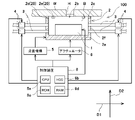
図1は本開示の一実施形態に係る超音波検査装置100の構成を示す断面図である。図1の超音波検査装置100は、被検体から反射した超音波を受信し、受信した超音波のエネルギーにより被検体に欠陥が存在するか否かを検査する方法、いわゆる反射法(局部水浸法)による探傷を行うものである。以下、本実施形態の超音波検査装置100について詳しく説明する。
FIG. 1 is a cross-sectional view showing the configuration of the ultrasonic inspection apparatus 100 according to the embodiment of the present disclosure. The ultrasonic inspection device 100 of FIG. 1 receives ultrasonic waves reflected from a subject and inspects whether or not a defect is present in the subject by the energy of the received ultrasonic waves, that is, a so-called reflection method (local water immersion). The flaw is detected by the law). Hereinafter, the ultrasonic inspection apparatus 100 of the present embodiment will be described in detail.
図1に示すように、本実施形態の超音波検査装置100は、超音波センサ1と、ケーシング2と、1又は複数の供給管3と、1又は複数のバルブ4と、走査機構5と、アクチュエータ6と、制御装置8とを備えている。
As shown in FIG. 1, the ultrasonic inspection device 100 of the present embodiment includes an ultrasonic sensor 1, a casing 2, one or more supply pipes 3, one or more valves 4, and a scanning mechanism 5. It includes an actuator 6 and a control device 8.
本実施形態において、被検体Wは例えば金属製又は炭素繊維強化プラスチック(CFRP:Carbon Fiber Reinforced Plastics)などの複合材であり、例えば数mm~20mm程度の厚さを有している。また、被検体Wは例えば航空機の胴体である。しかし、被検体Wは航空機の胴体に限られるものではない。このような被検体Wには、その厚さ方向に貫通する開口部Hが備わっている。開口部Hは例えば被検体Wの部品と部品との繋ぎ目における開口部などである。開口部Hの径は例えば2mm以上100mm以下である。
In the present embodiment, the subject W is, for example, a composite material such as metal or carbon fiber reinforced plastic (CFRP: Carbon Fiber Reinforced Plastics), and has a thickness of, for example, about several mm to 20 mm. The subject W is, for example, the fuselage of an aircraft. However, the subject W is not limited to the fuselage of the aircraft. Such a subject W is provided with an opening H penetrating in the thickness direction thereof. The opening H is, for example, an opening at a joint between the parts of the subject W and the parts. The diameter of the opening H is, for example, 2 mm or more and 100 mm or less.
超音波センサ1は、上記のような被検体Wの下方から当該被検体Wに対して超音波を照射する。また、超音波センサ1は、超音波を照射したあと被検体Wから反射した超音波を受信する。制御装置8は超音波センサ1から受信した超音波のエネルギーにより被検体Wに欠陥が存在するか否かを判別する。
The ultrasonic sensor 1 irradiates the subject W with ultrasonic waves from below the subject W as described above. Further, the ultrasonic sensor 1 receives the ultrasonic waves reflected from the subject W after irradiating the ultrasonic waves. The control device 8 determines whether or not a defect is present in the subject W based on the energy of the ultrasonic wave received from the ultrasonic sensor 1.
ケーシング2の硬度は被検体Wの硬度よりも低い。ケーシング2は例えば樹脂製である。このようなケーシング2には、超音波を伝播可能な接触媒質Bが充填されている。接触媒質Bとしては例えば水などの液体である。ケーシング2は、超音波センサ1を接触媒質Bに浸した状態で保持している。これにより、超音波センサ1から出射された超音波は接触媒質Bを伝播する。超音波センサ1は例えばネジ等の締結具によりケーシング2の後記の保持板部2a上に固定されている。なお、接触媒質Bの供給圧力による当該接触媒質Bに対する負荷を分散させるために、ケーシング2の容量は極力大きいことが望ましい。
The hardness of the casing 2 is lower than the hardness of the subject W. The casing 2 is made of, for example, resin. Such a casing 2 is filled with a contact medium B capable of propagating ultrasonic waves. The contact medium B is, for example, a liquid such as water. The casing 2 holds the ultrasonic sensor 1 immersed in the contact medium B. As a result, the ultrasonic waves emitted from the ultrasonic sensor 1 propagate through the contact medium B. The ultrasonic sensor 1 is fixed on the holding plate portion 2a described later of the casing 2 by, for example, a fastener such as a screw. It is desirable that the capacity of the casing 2 be as large as possible in order to disperse the load on the contact medium B due to the supply pressure of the contact medium B.
ケーシング2は、水平方向に延在する保持板部2a、および、保持板部2a上に設けられて当該保持板部2aに対して垂直な方向に延在する4つの側壁で構成されるケーシング側壁部2fを有している。すなわち、ケーシング2は上部に開口を有する容器のように形成されており、ケーシング側壁部2fのうち被検体W側の端部(上端部)に被検体側接触部2cを有すると共に、超音波センサ1に対向する側に開放された被検体側開口2bを有している。これにより、被検体側開口2bは被検体側接触部2cの内側に形成されている。なお、被検体側接触部2cが被検体側開口2bに設けられた面に相当する。本実施形態において、被検体側接触部2cは一水平面上に位置している。一方、航空機の胴体である被検体Wは平板状でないことがある。そのため、例えば図3に示すように、被検体Wが延在方向に曲率をもつ形状の場合、ケーシング2を被検体Wに当接させたとき、被検体側接触部2cのうちの一部が被検体Wに接触し、ケーシング2の被検体側接触部2cと被検体Wとの間に隙間21が存在する。
The casing 2 is a casing side wall composed of a holding plate portion 2a extending in the horizontal direction and four side walls provided on the holding plate portion 2a and extending in a direction perpendicular to the holding plate portion 2a. It has a portion 2f. That is, the casing 2 is formed like a container having an opening at the upper part, has a subject-side contact portion 2c at the end (upper end) of the casing side wall portion 2f on the subject W side, and is an ultrasonic sensor. It has a subject-side opening 2b that is open to the side facing 1. As a result, the subject-side opening 2b is formed inside the subject-side contact portion 2c. The subject-side contact portion 2c corresponds to a surface provided in the subject-side opening 2b. In the present embodiment, the subject-side contact portion 2c is located on a horizontal plane. On the other hand, the subject W, which is the fuselage of the aircraft, may not be flat. Therefore, for example, as shown in FIG. 3, when the subject W has a shape having a curvature in the extending direction, when the casing 2 is brought into contact with the subject W, a part of the subject-side contact portion 2c is formed. It comes into contact with the subject W, and there is a gap 21 between the subject-side contact portion 2c of the casing 2 and the subject W.
また、図2に示すように、ケーシング2は平面視において例えば矩形状である。ケーシング2の4つのケーシング側壁部2fには、接触媒質Bを排出するための複数の溝が設けられている。具体的には、ケーシング2の4つのケーシング側壁部2fのうち、矩形の短辺部分に位置する2つのケーシング側壁部2fの上部にはそれぞれ溝2dが設けられている。さらに4つのケーシング側壁部2fのうち、矩形の長辺部分に位置する2つのケーシング側壁部2fの上部にはそれぞれ2つの溝2eが設けられている。
Further, as shown in FIG. 2, the casing 2 has, for example, a rectangular shape in a plan view. The four casing side wall portions 2f of the casing 2 are provided with a plurality of grooves for discharging the contact medium B. Specifically, among the four casing side wall portions 2f of the casing 2, grooves 2d are provided in the upper portions of the two casing side wall portions 2f located on the short side portions of the rectangle. Further, of the four casing side wall portions 2f, two grooves 2e are provided on the upper portions of the two casing side wall portions 2f located on the long side portions of the rectangle.
溝2d,2eは、各ケーシング側壁部2fの被検体側接触部2cの一部が、下方に凹に切り欠かれることで形成されている。接触媒質Bは、溝2d,2eを介してケーシング2内から外方に排出される。なお、上述した通り、ケーシング2はそのケーシング側壁部2fの被検体側接触部2cのうちの少なくとも一部が被検体Wに接触しており、ケーシング2の被検体側接触部2cと被検体Wとの間に隙間21が存在する。そのため、接触媒質Bは、隙間21からも外方に排出される。このように、溝2d,2eおよび隙間21は排出口に相当し、ケーシング2内の接触媒質を外方へ排出する排出部20としての機能を有する。
The grooves 2d and 2e are formed by partially cutting out a part of the subject-side contact portion 2c of each casing side wall portion 2f in a concave shape downward. The contact medium B is discharged from the inside of the casing 2 to the outside through the grooves 2d and 2e. As described above, at least a part of the subject side contact portion 2c of the casing side wall portion 2f of the casing 2 is in contact with the subject W, and the subject side contact portion 2c and the subject W of the casing 2 are in contact with the subject W. There is a gap 21 between and. Therefore, the contact medium B is also discharged outward from the gap 21. As described above, the grooves 2d, 2e and the gap 21 correspond to the discharge port, and have a function as a discharge unit 20 for discharging the contact medium in the casing 2 to the outside.
隙間21は、以下の観点でコントロールすることが望ましい。接触媒質Bの排出量を制限するためには、溝2d,2e以外の排出箇所である隙間21を極力なくす必要がある。一方、隙間21をなくすためにケーシング2を被検体Wに押し付け過ぎると、当該被検体Wの表面等が損傷する場合がある。そこで、隙間21を極力なくしつつ、被検体Wの表面を損傷させない程度にケーシング2による押し付け力がコントロールされる。以上、ケーシング2の具体的構成について説明したが、当該ケーシング2の構成は上記構成に限定されるものではない。なお、図2においては、各構成要素の見易さを向上する観点で被検体Wの図示については省略したが、被検体Wの開口部Hのみ二点鎖線で図示している。また、超音波検査装置100が備える排出部20は、上述した溝2d,2eおよび隙間21のうち一部だけを有するものであってもよいし、これらとは異なる別の具体的な構成を採用してもよい。
It is desirable to control the gap 21 from the following viewpoints. In order to limit the discharge amount of the contact medium B, it is necessary to eliminate the gap 21 which is the discharge point other than the grooves 2d and 2e as much as possible. On the other hand, if the casing 2 is pressed too much against the subject W in order to eliminate the gap 21, the surface of the subject W may be damaged. Therefore, the pressing force by the casing 2 is controlled to the extent that the surface of the subject W is not damaged while eliminating the gap 21 as much as possible. Although the specific configuration of the casing 2 has been described above, the configuration of the casing 2 is not limited to the above configuration. In FIG. 2, the illustration of the subject W is omitted from the viewpoint of improving the visibility of each component, but only the opening H of the subject W is illustrated by a two-dot chain line. Further, the discharge unit 20 included in the ultrasonic inspection device 100 may have only a part of the grooves 2d, 2e and the gap 21 described above, or adopts a specific configuration different from these. You may.
供給管3は、本実施形態では複数設けられている。詳細には、図1においてケーシング2のケーシング側壁部2fの左方壁に例えば4本の供給管3が設けられ、当該ケーシング側壁部2fの右方壁に例えば4本の供給管3が設けられている。これらの供給管3によって接触媒質Bがケーシング2内に供給される。
A plurality of supply pipes 3 are provided in this embodiment. Specifically, in FIG. 1, for example, four supply pipes 3 are provided on the left wall of the casing side wall portion 2f of the casing 2, and for example, four supply pipes 3 are provided on the right wall of the casing side wall portion 2f. ing. The contact medium B is supplied into the casing 2 by these supply pipes 3.
各供給管3には、バルブ4がそれぞれ設けられる。制御装置8がバルブ4の開閉および開度を制御し、供給管3による接触媒質Bの供給の開始および停止、供給管3内を流れる接触媒質Bの流量調整を行う。なお、各供給管3における各バルブ4よりも上流側の部分には接触媒質Bを送り出すポンプと当該接触媒質Bを貯留するタンクが設けられている。
A valve 4 is provided in each supply pipe 3. The control device 8 controls the opening / closing and opening degree of the valve 4, starts and stops the supply of the contact medium B by the supply pipe 3, and adjusts the flow rate of the contact medium B flowing in the supply pipe 3. A pump for sending out the contact medium B and a tank for storing the contact medium B are provided in a portion of each supply pipe 3 on the upstream side of each valve 4.
各供給管3の径が小さすぎると接触媒質Bの流速が上がり圧力損失が大きくなる。それ故、同一ポンプを使用した場合に、径が大きい場合に比べて流量が低下するため、この点に留意して各供給管3の径を決定することが望ましい。また、供給管3の本数が少ないと一定以上の流量を確保することができないため、この点に留意して供給管3の本数を決定することが望ましい。また、各供給管3が長すぎると圧力損失が大きくなり、それ故、同一ポンプを使用した場合に、径が大きい場合に比べて流量が低下する。このため、この点に留意して各供給管3の長さを決定することが望ましい。さらに、接触媒質Bの供給圧力が小さいと流量が小さくなるため、ポンプ等で供給圧力を上げることが望ましい。
If the diameter of each supply pipe 3 is too small, the flow velocity of the contact medium B increases and the pressure loss increases. Therefore, when the same pump is used, the flow rate is lower than when the diameter is large, and it is desirable to determine the diameter of each supply pipe 3 in consideration of this point. Further, if the number of supply pipes 3 is small, it is not possible to secure a flow rate above a certain level, so it is desirable to determine the number of supply pipes 3 in consideration of this point. Further, if each supply pipe 3 is too long, the pressure loss becomes large, and therefore, when the same pump is used, the flow rate decreases as compared with the case where the diameter is large. Therefore, it is desirable to determine the length of each supply pipe 3 with this point in mind. Further, if the supply pressure of the contact medium B is small, the flow rate becomes small, so it is desirable to increase the supply pressure with a pump or the like.
走査機構5は、図2に示すように被検体Wの検査方向D3にケーシング2を走査させる。これにより、ケーシング2に保持された超音波センサ1は超音波を出射しつつ検査方向D3に走査される。なお、検査方向D3は被検体Wの厚さ方向に交差(具体的には直交)する方向である。走査機構5としては、公知のものを採用することができ、例えばケーシング2を保持するアームと、アームに連結されて当該アームを検査方向D3に往復移動させる例えばエアシリンダやボールねじおよびモータ等の直動アクチュエータとを含む走査機構が挙げられる。なお、方向D1は検査方向D3に直交する方向である。
The scanning mechanism 5 scans the casing 2 in the inspection direction D3 of the subject W as shown in FIG. As a result, the ultrasonic sensor 1 held in the casing 2 is scanned in the inspection direction D3 while emitting ultrasonic waves. The inspection direction D3 is a direction that intersects (specifically, orthogonally) with the thickness direction of the subject W. As the scanning mechanism 5, a known one can be adopted, for example, an arm holding the casing 2 and, for example, an air cylinder, a ball screw, a motor, etc., which are connected to the arm and reciprocate the arm in the inspection direction D3. Examples include a scanning mechanism including a linear actuator. The direction D1 is a direction orthogonal to the inspection direction D3.
アクチュエータ6は、例えばエアシリンダ等であり、ケーシング2のうち被検体側開口2bが設けられた面すなわちケーシング側壁部2fにおける被検体側接触部2cを、検査方向D3に垂直な方向である押し付け方向D2に押し上げる。ここで、押し付け方向D2は例えば鉛直上向きである。これにより、ケーシング側壁部2fの被検体側接触部2cが被検体Wに下方から押し付けられる。
The actuator 6 is, for example, an air cylinder or the like, and the surface of the casing 2 provided with the subject side opening 2b, that is, the subject side contact portion 2c on the casing side wall portion 2f is pressed in a direction perpendicular to the inspection direction D3. Push up to D2. Here, the pressing direction D2 is, for example, vertically upward. As a result, the subject-side contact portion 2c of the casing side wall portion 2f is pressed against the subject W from below.
制御装置8は、CPU8a,HDD8b,ROM8c,RAM8dを有している。HDD8bおよびRAM8dの一方又は両方は被検体Wの開口部Hの体積Vを予め記憶している。HDD8bおよびRAM8dがメモリに相当する。なお、被検体Wの開口部Hの体積Vについては後述する。
The control device 8 has a CPU 8a, an HDD 8b, a ROM 8c, and a RAM 8d. One or both of the HDD 8b and the RAM 8d previously stores the volume V of the opening H of the subject W. The HDD 8b and the RAM 8d correspond to the memory. The volume V of the opening H of the subject W will be described later.
このような構成において、制御装置8は、各供給管3による接触媒質Bの供給量、走査機構5による走査速度、アクチュエータ6による被検体Wに対するケーシング2の押し付け力を制御する。以下、本実施形態における制御装置8の制御について詳しく説明する。
In such a configuration, the control device 8 controls the supply amount of the contact medium B by each supply pipe 3, the scanning speed by the scanning mechanism 5, and the pressing force of the casing 2 against the subject W by the actuator 6. Hereinafter, the control of the control device 8 in the present embodiment will be described in detail.
接触媒質Bがケーシング2の開口部Hを介して被検体Wの内側に浸入する流量をzとし、ケーシング2の検査方向D3における走査時に当該ケーシング2の被検体側開口2bから開口部Hを通過するのに要する時間をtとする。また、被検体Wの開口部Hの体積(容積)をVとする。このとき、制御装置8は、0<z×t<Vを充足するように、各供給管3による接触媒質Bの供給量を制御すると共に、走査機構5によるケーシング2の走査速度を制御する(以下、制御装置8の上記制御を浸入防止制御と呼ぶ)。これにより、ケーシング2が開口部Hを通過する際の接触媒質の積算流量z×tが開口部Hの体積Vの体積を超えないよう制御されるため、水が被検体内部に侵入して探傷部の裏側に回り込むことにより超音波エコーが減衰することを防止し、良好な探傷データを得ることができる。また、接触媒質が被検体の内部に侵入することを防ぐために、開口部Hにシールを貼り付けたり、治具を嵌め込む必要がなくなり、作業工程が削減できる。
Let z be the flow rate at which the contact medium B penetrates into the inside of the subject W through the opening H of the casing 2, and the contact medium B passes through the opening H from the subject-side opening 2b of the casing 2 during scanning in the inspection direction D3 of the casing 2. Let t be the time required to do this. Further, the volume (volume) of the opening H of the subject W is V. At this time, the control device 8 controls the supply amount of the contact medium B by each supply pipe 3 so as to satisfy 0 <z × t <V, and also controls the scanning speed of the casing 2 by the scanning mechanism 5 ( Hereinafter, the control of the control device 8 is referred to as intrusion prevention control). As a result, the integrated flow rate z × t of the contact medium when the casing 2 passes through the opening H is controlled so as not to exceed the volume V of the volume V of the opening H, so that water invades the inside of the subject and detects a flaw. It is possible to prevent the ultrasonic echo from being attenuated by wrapping around to the back side of the portion, and to obtain good flaw detection data. Further, in order to prevent the contact medium from invading the inside of the subject, it is not necessary to attach a seal to the opening H or fit a jig, and the work process can be reduced.
なお、接触媒質の積算流量z×tの上限値は、上記に限られず、例えば接触媒質Bの表面張力を考慮した値としてもよい。接触媒質Bの表面張力によって接触媒質Bの外気との界面が開口部Hの内部にとどまるときに開口部内に存在できる最大の接触媒質の体積をSとする。制御装置8は、ケーシング2が開口部Hを通過する際の接触媒質の積算流量z×tの上限値がV+S以下となるように、各供給管3による接触媒質Bの供給量及び走査機構5によるケーシング2の走査速度を制御してもよい。積算流量の上限値をV以下とする場合に比べて体積Sの分だけ余裕ができることになるため、より制御が容易となる。
The upper limit of the integrated flow rate z × t of the contact medium is not limited to the above, and may be, for example, a value in consideration of the surface tension of the contact medium B. Let S be the maximum volume of the contact medium that can exist in the opening when the interface of the contact medium B with the outside air stays inside the opening H due to the surface tension of the contact medium B. The control device 8 supplies the contact medium B by each supply pipe 3 and the scanning mechanism 5 so that the upper limit of the integrated flow rate z × t of the contact medium when the casing 2 passes through the opening H is V + S or less. The scanning speed of the casing 2 may be controlled by the above. Compared with the case where the upper limit value of the integrated flow rate is V or less, a margin is provided by the volume S, so that the control becomes easier.
接触媒質Bがケーシング2の開口部Hを介して被検体Wの内側に浸入する流量zは、供給管3による接触媒質Bの供給量から、溝2d,2e及び隙間21から外方に排出される接触媒質Bの排出量を減算した値である。
The flow rate z at which the contact medium B infiltrates the inside of the subject W through the opening H of the casing 2 is discharged outward from the grooves 2d, 2e and the gap 21 from the supply amount of the contact medium B by the supply pipe 3. It is a value obtained by subtracting the emission amount of the contact medium B.
ここで、予めメモリには、体積V、体積S、接触媒質Bの供給量とポンプの供給圧力との関係を示すデータ、接触媒質Bの排出量と供給圧力との関係を示すデータ、接触媒質Bの排出量と被検体Wの形状および押し付け力との関係を示すデータ、ケーシング2が開口部Hを通過する時間tと走査機構5の制御量との関係を示すデータが記憶されており、これらに基づいて接触媒質Bの供給量及び排出量、すなわち流量zを得ることができる。
Here, in the memory in advance, the volume V, the volume S, the data showing the relationship between the supply amount of the contact medium B and the supply pressure of the pump, the data showing the relationship between the discharge amount of the contact medium B and the supply pressure, and the contact medium. Data showing the relationship between the discharge amount of B and the shape and pressing force of the subject W, and data showing the relationship between the time t for the casing 2 to pass through the opening H and the controlled amount of the scanning mechanism 5 are stored. Based on these, the supply amount and the discharge amount of the contact medium B, that is, the flow rate z can be obtained.
具体的には、接触媒質Bの供給量は、供給量とポンプの供給圧力との関係を示すデータに基づいて、ポンプの供給圧力を検知することにより得ることができる。また、接触媒質Bの排出量のうち、溝2d,2eからの排出量は、接触媒質Bの排出量と供給圧力との関係を示すデータ及び溝2d,2eの大きさに基づいて、供給圧力を検知することにより絵得られる。また、走査機構5としてエアシリンダを有するアクチュエータを用いる場合、隙間21からの排出量は、接触媒質Bの排出量と被検体Wの形状および押し付け力との関係を示すデータに基づいて、エアシリンダに対する圧縮空気圧を検知することにより得られる。さらに、ケーシング2が開口部Hを通過する時間tは、時間tと制御量との関係を示すデータに基づいて、アクチュエータを動作させるサーボモータの電圧又は電流を検知することにより得られる。
Specifically, the supply amount of the contact medium B can be obtained by detecting the supply pressure of the pump based on the data showing the relationship between the supply amount and the supply pressure of the pump. Further, among the discharge amounts of the contact medium B, the discharge amount from the grooves 2d and 2e is the supply pressure based on the data showing the relationship between the discharge amount of the contact medium B and the supply pressure and the size of the grooves 2d and 2e. A picture can be obtained by detecting. When an actuator having an air cylinder is used as the scanning mechanism 5, the discharge amount from the gap 21 is based on the data showing the relationship between the discharge amount of the contact medium B and the shape and pressing force of the subject W. It is obtained by detecting the compressed air pressure with respect to. Further, the time t through which the casing 2 passes through the opening H is obtained by detecting the voltage or current of the servomotor that operates the actuator based on the data indicating the relationship between the time t and the control amount.
制御装置8は、浸入防止制御を実行する際に、上記の各パラメータを取得し、0<z×t<Vを充足するように接触媒質Bの供給量およびケーシング2の走査速度を制御する。また、制御装置8は、0<z×t<Vを充足させるために、被検体Wに対するケーシング2の押圧力が所定範囲となるようにアクチュエータ6の動作を制御する。
The control device 8 acquires each of the above parameters when executing the intrusion prevention control, and controls the supply amount of the contact medium B and the scanning speed of the casing 2 so as to satisfy 0 <z × t <V. Further, the control device 8 controls the operation of the actuator 6 so that the pressing force of the casing 2 with respect to the subject W is within a predetermined range in order to satisfy 0 <z × t <V.
なお、体積V、体積S、上記の関係を示す各種データは超音波検査装置100のメモリに記憶されているがこれに限られない。これらは通信回線を介して外部が取得してもよいし、外部のメモリから取得してもよい。
Note that the volume V, the volume S, and various data showing the above relationship are stored in the memory of the ultrasonic inspection device 100, but the present invention is not limited to this. These may be acquired externally via a communication line or may be acquired from an external memory.
ここまで制御装置8による浸入防止制御について説明したが、当該制御を実現するための構成は例示した構成に限定されない。本明細書で開示する機能は、当該機能を実行するよう構成またはプログラムされた汎用プロセッサ、専用プロセッサ、集積回路、ASIC(Application Specific Integrated Circuits)、従来の回路、および/または、それらの組み合わせ、を含む回路または処理回路を使用して実行できる。プロセッサは、トランジスタやその他の回路を含むため、処理回路または回路と見なされる。本開示において、回路、ユニット、または手段は、列挙された機能を実行するハードウエアであるか、または、列挙された機能を実行するようにプログラムされたハードウエアである。ハードウエアは、本明細書に開示されているハードウエアであってもよいし、あるいは、列挙された機能を実行するようにプログラムまたは構成されているその他の既知のハードウエアであってもよい。ハードウエアが回路の一種と考えられるプロセッサである場合、回路、手段、またはユニットはハードウエアとソフトウエアの組み合わせであり、ソフトウエアはハードウエアおよび/またはプロセッサの構成に使用される。
Although the intrusion prevention control by the control device 8 has been described so far, the configuration for realizing the control is not limited to the illustrated configuration. The functions disclosed herein include general-purpose processors, dedicated processors, integrated circuits, ASICs (Application Specific Integrated Circuits), conventional circuits, and / or combinations thereof, configured or programmed to perform such functions. It can be executed using the included circuit or processing circuit. A processor is considered a processing circuit or circuit because it contains transistors and other circuits. In the present disclosure, a circuit, unit, or means is hardware that performs the listed functions or is programmed to perform the listed functions. The hardware may be the hardware disclosed herein, or it may be other known hardware that is programmed or configured to perform the listed functions. If the hardware is a processor considered to be a type of circuit, the circuit, means, or unit is a combination of hardware and software, and the software is used to configure the hardware and / or the processor.
(変形例)
上述の実施形態の他にも、本開示は、その要旨を逸脱しない範囲で次のような種々の変形が可能である。
(Modification example)
In addition to the above-described embodiments, the present disclosure allows various modifications as follows without departing from the gist thereof.
上記実施形態では、ケーシング側壁部2fのうち被検体W側の端部に被検体側接触部2cを設ける態様について説明を行ったが、ケーシング2の、被検体Wに接触する部分の態様は上記態様に限定されるものではない。図4は図1の超音波検査装置の変形例を示す断面図である。
In the above embodiment, the embodiment in which the subject side contact portion 2c is provided at the end portion of the casing side wall portion 2f on the subject W side has been described, but the embodiment of the portion of the casing 2 in contact with the subject W is described above. It is not limited to the embodiment. FIG. 4 is a cross-sectional view showing a modified example of the ultrasonic inspection apparatus of FIG.
図4に示すように、変形例に係る超音波検査装置100Aにおけるケーシング2Aは、ケーシング側壁部2fのうちの被検体W側の端部に設けられた被検体側接触部2gを有している。この被検体側接触部2gは、ケーシング側壁部2fの上記端部からケーシング2の内側に向かって延在する。このような構成によって、被検体側接触部2cよりも、被検体側接触部2gと被検体Wとの接触面積を増やすことができる。これにより、図3の態様における隙間21よりも、被検体Wとケーシング2Aとの隙間を極力減らすことが可能となる。
As shown in FIG. 4, the casing 2A in the ultrasonic inspection apparatus 100A according to the modified example has a subject side contact portion 2g provided at an end portion of the casing side wall portion 2f on the subject W side. .. The subject-side contact portion 2g extends from the end portion of the casing side wall portion 2f toward the inside of the casing 2. With such a configuration, the contact area between the subject side contact portion 2g and the subject W can be increased more than the subject side contact portion 2c. This makes it possible to reduce the gap between the subject W and the casing 2A as much as possible, as compared with the gap 21 in the aspect of FIG.
また、上記実施形態では、被検体Wとして航空機の胴体を例として挙げたが、被検体Wの種類としてはこれに限定されるものではなく、種々の機械や当該機械を構成する部品などを被検体Wとして用いることができる。また、被検体Wの断面形状については、例えば平板状、U字状、T字状、I字状、又はL字状等の種々の形状であってもよい。
Further, in the above embodiment, the fuselage of the aircraft is taken as an example of the subject W, but the type of the subject W is not limited to this, and various machines and parts constituting the machine are covered. It can be used as a sample W. Further, the cross-sectional shape of the subject W may be various shapes such as a flat plate shape, a U shape, a T shape, an I shape, or an L shape.
また、上記実施形態では、複数の供給管3を設けることとしたが、これに限定されるものではなく、所望の供給圧力および所望の供給量を確保することが可能であれば、供給管3を例えば1本としてもよい。
Further, in the above embodiment, a plurality of supply pipes 3 are provided, but the present invention is not limited to this, and if it is possible to secure a desired supply pressure and a desired supply amount, the supply pipe 3 is provided. For example, one may be used.
さらに、上記実施形態では、ケーシング2の硬度を被検体Wの硬度よりも低くすべく、当該ケーシング2を樹脂製としたが、これに限定されるものではない。ケーシング2の硬度が被検体Wの硬度よりも低くて耐摩耗性を有するものであれば、ケーシング2を他の材質で形成してもよい。
Further, in the above embodiment, the casing 2 is made of resin in order to make the hardness of the casing 2 lower than the hardness of the subject W, but the casing 2 is not limited to this. If the hardness of the casing 2 is lower than the hardness of the subject W and has wear resistance, the casing 2 may be formed of another material.
本開示の超音波検査装置は、開口部を有する被検体に対して超音波を照射して前記被検体の探傷を行う超音波検査装置であって、前記被検体の下方から当該被検体に対して前記超音波を照射する超音波センサと、前記超音波が伝播可能な接触媒質に浸した状態で前記超音波センサ保持し、前記超音波センサに対向する側に被検体側開口を有するケーシングと、前記ケーシング内に前記接触媒質を供給する供給管と、前記被検体の検査方向に前記ケーシングを走査させる走査機構と、制御装置と、を備え、前記制御装置は、前記接触媒質が前記開口部を介して前記被検体の内側に浸入する流量をzとし、前記ケーシングの前記被検体側開口が前記検査方向において前記開口部を通過するのに要する時間をtとし、前記開口部の体積をVとするとき、前記接触媒質の供給量および前記走査機構による前記ケーシングの走査速度を制御して0<z×t<Vを充足するするものである。
The ultrasonic inspection device of the present disclosure is an ultrasonic inspection device that irradiates a subject having an opening with ultrasonic waves to detect the subject, and the subject is subjected to the ultrasonic inspection from below the subject. An ultrasonic sensor that irradiates the ultrasonic waves, and a casing that holds the ultrasonic sensor in a state of being immersed in a contact medium through which the ultrasonic waves can propagate and has an opening on the subject side on the side facing the ultrasonic sensor. A supply pipe for supplying the contact medium into the casing, a scanning mechanism for scanning the casing in the inspection direction of the subject, and a control device are provided. In the control device, the contact medium is the opening. Let z be the flow rate of penetration into the inside of the subject through the lens, t be the time required for the subject-side opening of the casing to pass through the opening in the inspection direction, and the volume of the opening be V. Then, the supply amount of the contact medium and the scanning speed of the casing by the scanning mechanism are controlled to satisfy 0 <z × t <V.
本開示に従えば、制御装置によって、0<z×t<Vが充足されるように、供給管による接触媒質の供給量が制御されると共に走査機構によるケーシングの走査速度が制御される。これにより、被検体の開口部から被検体の内側に水が侵入することを防止することができる。このことによって、従来必要であった、開口部にシールを貼り付ける工程や治具を嵌め込む工程、さらにはシールを剥離する工程や治具を取り外す工程が不要となる。また、上記のシール貼り付けによって生じる探傷不能部分が発生しえないため、少なくともこの探傷不能部分のために手動探傷を別途実施する必要もない。
According to the present disclosure, the control device controls the supply amount of the contact medium by the supply pipe and the scanning speed of the casing by the scanning mechanism so that 0 <z × t <V is satisfied. This makes it possible to prevent water from entering the inside of the subject through the opening of the subject. This eliminates the conventionally required steps of attaching a seal to the opening, fitting a jig, peeling the seal, and removing the jig. Further, since the non-detectable portion caused by the sticking of the sticker cannot occur, it is not necessary to separately perform manual flaw detection at least for this non-detectable portion.
上記開示において、前記制御装置は、前記接触媒質の表面張力によって当該接触媒質の外気との界面が前記開口部の内部にとどまるときに前記開口部内に存在できる最大の前記接触媒質の体積をSとするとき、前記接触媒質の供給量および前記走査機構による前記ケーシングの走査速度を制御して0<z×t<V+Sを充足してもよい。
In the above disclosure, the control device uses S as the maximum volume of the contact medium that can exist in the opening when the interface of the contact medium with the outside air stays inside the opening due to the surface tension of the contact medium. At that time, 0 <z × t <V + S may be satisfied by controlling the supply amount of the contact medium and the scanning speed of the casing by the scanning mechanism.
上記構成に従えば、制御装置によって、0<z×t<V+Sを充足するように接触媒質の供給量を制御すると共にケーシングの走査速度が制御される。このように充足要件をよりシビアに考慮して制御装置による上記制御を行うことで、被検体の開口部から被検体の内側に水が侵入することを防止できる信頼性を著しく高めることができる。
According to the above configuration, the control device controls the supply amount of the contact medium so as to satisfy 0 <z × t <V + S, and also controls the scanning speed of the casing. By performing the above control by the control device in consideration of the satisfaction requirement more severely in this way, it is possible to remarkably enhance the reliability that can prevent water from entering the inside of the subject through the opening of the subject.
上記開示において、超音波検査装置は、前記ケーシング内の前記接触媒質を外方へ排出する排出部をさらに備え、前記制御装置は、前記流量zを、前記供給管による前記接触媒質の供給量から、前記排出部により外方に排出される前記接触媒質の量を減算したものとして、前記接触媒質の供給量および前記走査機構による前記ケーシングの走査速度を制御してもよい。
In the above disclosure, the ultrasonic inspection device further includes a discharge unit that discharges the contact medium in the casing to the outside, and the control device draws the flow rate z from the supply amount of the contact medium by the supply pipe. , The supply amount of the contact medium and the scanning speed of the casing by the scanning mechanism may be controlled by subtracting the amount of the contact medium discharged outward by the discharging unit.
上記構成に従えば、算出された正確な流量zに基づき接触媒質の供給量および走査機構によるケーシングの走査速度を制御することができる。
According to the above configuration, the supply amount of the contact medium and the scanning speed of the casing by the scanning mechanism can be controlled based on the calculated accurate flow rate z.
上記開示において、超音波検査装置は、前記ケーシングのうち前記被検体側開口が設けられた面を前記被検体に押し付けるアクチュエータをさらに備え、前記排出部は、前記接触媒質を排出する複数の排出口を含み、前記排出口の少なくとも1つは、前記ケーシングと前記被検体との間の隙間であり、前記制御装置は、前記アクチュエータの動作を制御して前記被検体と前記ケーシングとの隙間を減少させてもよい。
In the above disclosure, the ultrasonic inspection device further includes an actuator that presses the surface of the casing provided with the subject-side opening against the subject, and the discharge unit has a plurality of discharge ports for discharging the contact medium. At least one of the outlets is a gap between the casing and the subject, and the control device controls the operation of the actuator to reduce the gap between the subject and the casing. You may let me.
上記構成に従えば、多くの探傷においてケーシングの一部分と被検体との間に隙間が存在することを考慮して、流量zを算出する際に上記隙間により外方に排出される接触媒質の量を含めるようにした。このことによって、流量zをより正確に算出することができる。また、被検体に対するケーシングの押圧力を所定範囲にすることで、被検体を多少変形させながらでも上記隙間を極力小さくすることができる。
According to the above configuration, considering that there is a gap between a part of the casing and the subject in many flaw detections, the amount of the contact medium discharged outward by the gap when calculating the flow rate z. Was included. This makes it possible to calculate the flow rate z more accurately. Further, by setting the pressing force of the casing with respect to the subject within a predetermined range, the gap can be made as small as possible while the subject is slightly deformed.
上記開示において、超音波検査装置は、前記供給管による前記接触媒質の供給量を増減するバルブをさらに備え、前記制御装置は、前記バルブの開度で制御してもよい。
In the above disclosure, the ultrasonic inspection device may further include a valve for increasing or decreasing the supply amount of the contact medium by the supply pipe, and the control device may be controlled by the opening degree of the valve.
上記構成に従えば、接触媒質を必要以上に供給した場合に当該接触媒質が被検体の開口部から侵入してしまうことを回避することができる。
According to the above configuration, it is possible to prevent the contact medium from invading through the opening of the subject when the contact medium is supplied more than necessary.
上記開示において、前記ケーシングの硬度は前記被検体の硬度よりも低くてもよい。
In the above disclosure, the hardness of the casing may be lower than the hardness of the subject.
上記構成に従えば、アクチュエータによってケーシングを所定の押圧力で被検体に対して押し付けても、当該被検体に損傷(例えば引っ掻き傷など)を与えることを回避することができる。
According to the above configuration, even if the casing is pressed against the subject with a predetermined pressing force by the actuator, it is possible to avoid damaging the subject (for example, scratches).
上記開示において、前記ケーシングは樹脂製であってもよい。
In the above disclosure, the casing may be made of resin.
上記構成に従えば、ケーシングを樹脂製としたことによって、上記の通りケーシングによる押圧により被検体に損傷(例えば引っ掻き傷など)を与えることを回避することができると共に、当該ケーシングの低コスト化を図ることができる。また、ケーシングを樹脂製とすることで、摩擦低減により被検体に対するケーシングの滑りを良くすることができる。この場合、樹脂表面の面粗度を考慮することで上記滑りをより良くすることが可能である。
According to the above configuration, by making the casing made of resin, it is possible to avoid damaging the subject (for example, scratches) due to pressing by the casing as described above, and to reduce the cost of the casing. Can be planned. Further, by making the casing made of resin, it is possible to improve the sliding of the casing with respect to the subject by reducing the friction. In this case, it is possible to improve the slip by considering the surface roughness of the resin surface.