WO2022071564A1 - 内視鏡 - Google Patents
内視鏡 Download PDFInfo
- Publication number
- WO2022071564A1 WO2022071564A1 PCT/JP2021/036390 JP2021036390W WO2022071564A1 WO 2022071564 A1 WO2022071564 A1 WO 2022071564A1 JP 2021036390 W JP2021036390 W JP 2021036390W WO 2022071564 A1 WO2022071564 A1 WO 2022071564A1
- Authority
- WO
- WIPO (PCT)
- Prior art keywords
- wire
- fixing
- catch
- hole
- locked
- Prior art date
- Legal status (The legal status is an assumption and is not a legal conclusion. Google has not performed a legal analysis and makes no representation as to the accuracy of the status listed.)
- Ceased
Links
Images

















Classifications
-
- A—HUMAN NECESSITIES
- A61—MEDICAL OR VETERINARY SCIENCE; HYGIENE
- A61B—DIAGNOSIS; SURGERY; IDENTIFICATION
- A61B1/00—Instruments for performing medical examinations of the interior of cavities or tubes of the body by visual or photographical inspection, e.g. endoscopes; Illuminating arrangements therefor
- A61B1/00064—Constructional details of the endoscope body
- A61B1/00071—Insertion part of the endoscope body
- A61B1/0008—Insertion part of the endoscope body characterised by distal tip features
- A61B1/00098—Deflecting means for inserted tools
-
- A—HUMAN NECESSITIES
- A61—MEDICAL OR VETERINARY SCIENCE; HYGIENE
- A61B—DIAGNOSIS; SURGERY; IDENTIFICATION
- A61B1/00—Instruments for performing medical examinations of the interior of cavities or tubes of the body by visual or photographical inspection, e.g. endoscopes; Illuminating arrangements therefor
- A61B1/00002—Operational features of endoscopes
- A61B1/00039—Operational features of endoscopes provided with input arrangements for the user
- A61B1/00042—Operational features of endoscopes provided with input arrangements for the user for mechanical operation
-
- A—HUMAN NECESSITIES
- A61—MEDICAL OR VETERINARY SCIENCE; HYGIENE
- A61B—DIAGNOSIS; SURGERY; IDENTIFICATION
- A61B1/00—Instruments for performing medical examinations of the interior of cavities or tubes of the body by visual or photographical inspection, e.g. endoscopes; Illuminating arrangements therefor
- A61B1/00064—Constructional details of the endoscope body
- A61B1/00071—Insertion part of the endoscope body
- A61B1/0008—Insertion part of the endoscope body characterised by distal tip features
- A61B1/00101—Insertion part of the endoscope body characterised by distal tip features the distal tip features being detachable
-
- A—HUMAN NECESSITIES
- A61—MEDICAL OR VETERINARY SCIENCE; HYGIENE
- A61B—DIAGNOSIS; SURGERY; IDENTIFICATION
- A61B1/00—Instruments for performing medical examinations of the interior of cavities or tubes of the body by visual or photographical inspection, e.g. endoscopes; Illuminating arrangements therefor
- A61B1/00112—Connection or coupling means
- A61B1/00121—Connectors, fasteners and adapters, e.g. on the endoscope handle
- A61B1/00128—Connectors, fasteners and adapters, e.g. on the endoscope handle mechanical, e.g. for tubes or pipes
-
- A—HUMAN NECESSITIES
- A61—MEDICAL OR VETERINARY SCIENCE; HYGIENE
- A61B—DIAGNOSIS; SURGERY; IDENTIFICATION
- A61B1/00—Instruments for performing medical examinations of the interior of cavities or tubes of the body by visual or photographical inspection, e.g. endoscopes; Illuminating arrangements therefor
- A61B1/012—Instruments for performing medical examinations of the interior of cavities or tubes of the body by visual or photographical inspection, e.g. endoscopes; Illuminating arrangements therefor characterised by internal passages or accessories therefor
- A61B1/018—Instruments for performing medical examinations of the interior of cavities or tubes of the body by visual or photographical inspection, e.g. endoscopes; Illuminating arrangements therefor characterised by internal passages or accessories therefor for receiving instruments
-
- G—PHYSICS
- G02—OPTICS
- G02B—OPTICAL ELEMENTS, SYSTEMS OR APPARATUS
- G02B23/00—Telescopes, e.g. binoculars; Periscopes; Instruments for viewing the inside of hollow bodies; Viewfinders; Optical aiming or sighting devices
- G02B23/24—Instruments or systems for viewing the inside of hollow bodies, e.g. fibrescopes
Definitions
- the present invention relates to an endoscope, and particularly relates to an endoscope provided with a stand on the tip end side of an insertion portion to change the direction in which the treatment tool is taken out.
- various treatment tools are introduced from the treatment tool introduction port provided in the operation part, and this treatment tool is taken out from the treatment tool outlet opened at the tip of the insertion part and used for treatment.
- a treatment tool such as a guide wire or a contrast tube is used.
- Treatment tools such as puncture needles are used in ultrasonic endoscopes.
- treatment tools such as forceps or snares are used.
- Such a treatment tool needs to change the lead-out direction at the tip in order to treat a desired position in the subject. Therefore, the tip main body of the tip is provided with an upright stand for changing the direction of taking out the treatment tool.
- the endoscope is provided with a treatment tool standing mechanism that displaces the posture of the standing table between the standing position and the lying position.
- the endoscope disclosed in Patent Document 1 has a stand on the tip side of the work channel.
- the pedestal is rotated around the pivot axis by a wire so that the medical device can be accurately directed to the surgical area.
- the base end side of the wire is inserted into the collet, then the collet is tightened by rotating the nut and the collet secures the wire.
- the fixing force may not be sufficiently exerted depending on the tightening condition, or the wire fixing end may be gripped by the collet at a halfway position (for example, when there is almost no gripping margin at the wire fixing end). If it is fixed in the above state, the wire may come off from the collet during the standing operation.
- the present invention has been made in view of such circumstances, and an object of the present invention is to provide an endoscope capable of reliably fixing an upright operation wire to a wire fixing mechanism.
- the endoscope of the present invention has an operation portion provided with an operation member, an insertion portion provided on the tip end side of the operation portion, and an insertion portion inserted into a subject, and an insertion portion.
- An upright operation wire provided at the tip portion, an upright operation wire whose tip side is connected to the treatment tool upright table, and which is pushed and pulled according to the operation of the operating member to operate the treatment tool upright stand, and an upright operation wire.
- the wire fixing mechanism is provided with a wire fixing mechanism for fixing the base end side of the wire catch, and the wire fixing mechanism has a wire catch that detachably locks and fixes the base end side of the standing operation wire, and a wire shaft of the standing operation wire.
- the standing operation wire is a long wire body. It has a locked portion that is located on the base end side of the wire and is formed in an outer shape larger than the wire body, and the wire catch has a locking hole that can be locked by inserting the locked portion and a locking hole. It has a locked portion inserted into the wire and a fixing portion for fixing the locked state of the locking hole.
- the fixed portion has a regulating surface that regulates the movement of the locked portion in the locked state with the locking hole in the direction orthogonal to the wire axial direction.
- the fixing portion has a fixing hole formed with an opening that can accept the locked portion, and at least a part of the inner wall surface of the fixing hole is configured as a regulating surface. Is preferable.
- the fixing hole preferably has a conical guide surface that tapers toward the inside of the fixing hole.
- the locking hole has a first hole having a size through which the locked portion can be inserted, and a size larger than the outer shape of the wire body and smaller than the outer shape of the locked portion. It is preferable that the second hole has a continuous opening shape.
- the wire catch is rotatably configured around a rotation axis eccentric from the standing operation wire, the locking hole is provided at a position eccentric from the rotation axis, and the rotation axis is formed. It is preferable that the first hole and the second hole are continuously formed along the centered rotation locus.
- the fixing portion releases the fixing position for fixing the locked state between the locked portion and the locking hole and the locking state between the locked portion and the locking hole. It is preferable that it can be moved to and from the release position.
- the operating portion has a link member that operates in conjunction with the operation of the operating member
- the sliding lever has a lever connecting portion that can be detachably connected to the link member. It is preferable that the fixed portion can be moved between the fixed position and the release position in conjunction with the lever connecting operation for connecting the lever connecting portion to the link member.
- the operating portion has a link member that operates in conjunction with the operation of the operating member
- the sliding lever has a lever connecting portion that can be detachably connected to the link member.
- the wire fixing mechanism allows a regulated state that regulates the lever connecting operation for connecting the lever connecting part to the link member when the fixed part is in the release position, and allows the lever connecting operation when the fixed part is in the fixed position. It is preferable to have an operation control unit that can selectively switch between the allowable state and the allowable state.
- the wire catch has a locking member having a locking hole, and the locking member has an insertion position where the locked portion can be inserted into the locking hole and a locked portion. Is preferably movable to and from the locking position where the is locked in the locking hole.
- the standing operation wire can be reliably fixed to the wire fixing mechanism.
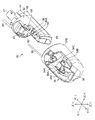
- Front view of wire fixing mechanism Perspective view of the main part with the cap removed from the wire fixing mechanism shown in FIG.
- Perspective view of the main part showing the configuration of the sliding lever
- Sectional drawing of the wire fixing mechanism along the XVI-XVI line of FIG. Explanatory drawing showing a state in which the locked portion protrudes from the locking hole.
- Explanatory drawing showing a state in which a wire protrudes from a locking hole Explanatory drawing showing a state in which the wire is locked in the second hole.
- Front view showing the state where the lever connection operation is started Explanatory drawing showing a state in which the locked portion is engaged with the concave portion in the middle of the lever connecting operation.
- Front view showing the state where the first half of the lever connection operation is completed Sectional drawing of the wire fixing mechanism in the state of FIG. 24
- Front view showing the state where the lever connection operation is completed Explanatory drawing showing a wire fixing range and a driving range
- a perspective view showing the wire fixing mechanism of the second embodiment Front view of the wire fixing mechanism shown in FIG. 29. Sectional drawing of the wire fixing mechanism shown in FIG.
- FIG. 32 Front view of the wire fixing mechanism in which the fixing member is moved in the Y (+) direction.
- Sectional drawing of the wire fixing mechanism shown in FIG. 32 Front view of the wire fixing mechanism when the lever connection operation is started Front view of the wire fixing mechanism in which the second axis is in contact with the regulation surface Sectional drawing which showed the main part of the wire fixing mechanism which concerns on 3rd Embodiment Perspective view of the wire fixing mechanism according to the fourth embodiment Perspective view of the wire fixing mechanism according to the fifth embodiment
- Sectional drawing of the wire fixing mechanism shown in FIG. 38 Perspective view of the wire fixing mechanism according to the sixth embodiment Sectional drawing of the wire fixing mechanism shown in FIG. 40
- FIG. 1 is a block diagram of an endoscope system 12 including an endoscope 10 according to an embodiment of the present invention.
- the endoscope system 12 includes an endoscope 10, an endoscope processor device 14, and a display 18.
- the endoscope 10 includes a hand operation unit 22 provided with a standing operation lever 20 and an insertion unit 24 provided on the tip end side of the hand operation unit 22 and inserted into a subject.
- the hand operation unit 22 functions as the operation unit of the present invention.
- the insertion portion 24 has a long axis direction Ax from the proximal end portion to the distal end portion, and includes a flexible portion 26, a curved portion 28, and a distal end portion 30 in order from the proximal end side to the distal end side.
- the detailed configuration of the tip portion 30 will be described later, but first, a schematic configuration of the tip portion 30 will be described.
- FIG. 2 is an enlarged perspective view of the tip portion 30.
- the endoscope 10 of the embodiment is a side endoscope used as, for example, a duodenal endoscope
- the tip portion 30 of FIG. 2 has a configuration of a side endoscope. ..
- the tip portion 30 is configured by attaching a cap 34 to the tip portion main body 32.
- the cap 34 is provided with a treatment tool standing table 36 (hereinafter, referred to as a standing table 36) having a treatment tool guide surface 36A, and shows a state in which the standing table 36 is positioned in an inverted position.
- FIG. 2 shows various contents arranged inside the insertion portion 24 of the endoscope 10 (see FIG. 1) in addition to the tip portion 30. That is, in FIG. 2, an operation is performed to change the lead-out direction of the treatment tool channel 37 that guides the tip portion of the treatment tool (not shown) to the tip portion main body 32 and the tip portion of the treatment tool derived from the tip portion main body 32.
- An upright operation wire 38 (hereinafter referred to as a wire 38), a wire channel 40 composed of a close contact spring through which the wire 38 is inserted, an air supply / water supply tube 42, and a cable insertion channel 44 are shown. ing.
- an angle wire (not shown) for bending the insertion channel 45 of the light guide that guides the illumination light supplied from the light source device 15 (see FIG. 1) to the tip main body 32 and the curved portion 28 (see FIG. 1). ) And the like are also arranged inside the insertion portion 24.
- a three-dimensional Cartesian coordinate system in the three-axis direction (X-axis direction, Y-axis direction, Z-axis direction) will be described. That is, when the tip portion 30 is viewed from the hand operation unit 22 and the direction in which the treatment tool (not shown) is drawn out by the standing table 36 is the upward direction, the upward direction is the Z (+) direction and the opposite direction. The downward direction is the Z (-) direction. Further, the right direction at that time is the X (+) direction, and the left direction is the X ( ⁇ ) direction.
- the front direction (the direction toward the tip end side in the long axis direction Ax direction of the insertion portion 24) at that time is the Y (+) direction
- the rear direction (the base end side in the direction of the long axis direction Ax of the insertion portion 24).
- Direction is the Y (-) direction.
- the Y-axis direction including the Y (+) direction and the Y ( ⁇ ) direction is parallel to the long axis direction Ax direction of the insertion portion 24 and the wire axis direction of the wire 38.
- the Y (+) direction points to the tip end side in the wire axis direction
- the Y ( ⁇ ) direction points to the base end side in the wire axis direction.
- the Z-axis direction is a direction orthogonal to the long-axis direction Ax
- the X-axis direction is a direction orthogonal to the Y-axis direction and the Z-axis direction, respectively.
- the hand operation unit 22 is configured to have a substantially cylindrical shape as a whole.
- the hand operation unit 22 has an operation unit main body 46 provided with an standing operation lever 20 and a grip portion 48 connected to the operation unit main body 46.
- the grip portion 48 is a portion that is gripped by the operator when the endoscope 10 is operated, and the base end portion of the insertion portion 24 is connected to the tip end side of the grip portion 48 via a breakage tube 50.
- the base end portion of the universal cable 52 is connected to the operation unit main body 46, and the connector device 54 is provided at the tip end portion of the universal cable 52.
- the connector device 54 is connected to the endoscope processor device 14.
- the endoscope processor device 14 includes a light source device 15 and an image processing device 16.
- the light source device 15 is provided with a processor-side connector 15A to which the connector device 54 is connected.
- a display 18 for displaying an image processed by the image processing device 16 is connected to the image processing device 16.
- the endoscope system 12 transmits power, optical signals, and the like between the endoscope 10 and the endoscope processor device 14 via a connector portion composed of a connector device 54 and a processor-side connector 15A. It has a configuration for non-contact transmission.
- the light from the light source device 15 is transmitted via an optical fiber cable (not shown) and is emitted from the illumination window 74 (see FIG. 2) provided on the tip surface of the tip portion 30.
- the optical signal obtained by capturing and converting the light captured from the observation window 76 (see FIG. 2) by the image pickup device is image-processed by the image processing device 16 and displayed as an image on the display 18.
- the air supply / water supply button 57 and the suction button 59 are arranged side by side on the operation unit main body 46.
- the air supply / water supply button 57 is a button that can be operated in two stages, and air can be supplied to the air supply / water supply nozzle 58 (see FIG. 2) via the air supply / water supply tube 42 by the first stage operation. Water can be supplied to the air supply / water supply nozzle 58 via the air supply / water supply tube 42 by the operation of the step. Further, when the suction button 59 is operated, body fluid such as blood can be sucked from the treatment tool outlet 60 (FIG. 2) via the treatment tool channel 37.
- a pair of angle knobs 62, 62 for bending the curved portion 28 are arranged on the operation unit main body 46.
- the pair of angle knobs 62, 62 are provided coaxially and rotatably.
- four angle wires (not shown) are connected to the angle knobs 62 and 62 and the curved portion 28, and these angle wires are pushed and pulled by the rotation operation of the angle knobs 62 and 62.
- the curved portion 28 is curved vertically and horizontally.
- the operation unit main body 46 is provided with a standing operation lever 20 rotatably coaxially with the angle knobs 62 and 62.
- the standing operation lever 20 is rotationally operated by the operator who grips the grip portion 48.
- the standing operation lever 20 functions as an operation member of the present invention.
- a wire fixing mechanism 78 which is the first embodiment of the wire fixing mechanism of the present invention, is provided outside the operation unit main body 46.
- the wire fixing mechanism 78 has a sliding lever 80 and a fixing unit 82, and has a configuration for fixing the base end side of the wire 38 (see FIG. 2) as described later.
- One end of the sliding lever 80 is detachably connected to the standing operation lever 20 side, and moves (slides) in conjunction with the rotation operation of the standing operation lever 20.
- the fixing unit 82 is provided at the other end of the sliding lever 80.
- the fixing unit 82 is attached to the operation unit main body 46, and the base end side of the wire 38 is fixed to the fixing unit 82.
- the wire fixing mechanism 78 will be described later.
- the grip portion 48 of the hand operation unit 22 includes a treatment tool introduction port 64 for introducing the treatment tool.
- the treatment tool (not shown) introduced from the treatment tool introduction port 64 with the tip portion at the head is inserted into the treatment tool channel 37 shown in FIG. 2 and is led out from the treatment tool outlet 60 to the outside.
- the treatment tool include a biopsy forceps having a cup capable of collecting biological tissue at the tip, a knife for EST (Endoscopic Sphincterotomy), or a contrast tube.
- the tip main body 32 is made of, for example, a metal material having corrosion resistance, and has a partition wall 68 projecting in the Y (+) direction.
- the standing table accommodating space (not shown) is defined by the partition wall 68 and the wall portion 34B of the cap 34.
- a through hole 61 is formed in the tip main body 32, and the wire 38 is inserted through the through hole 61.
- An illumination window 74 and an observation window 76 are arranged adjacent to each other in the Y direction on the upper surface 68A on the Z (+) side of the partition wall 68.
- the illumination window 74 can irradiate the visual field region in the Z (+) direction with illumination light, and the observation window 76 can observe the visual field region in the Z (+) direction.
- the tip main body 32 is provided with an air supply / water supply nozzle 58 toward the observation window 76, and the observation window 76 is washed by air and water ejected from the air supply / water supply nozzle 58.
- the cap 34 is made of an elastic material such as a rubber material or a resin material.
- the rubber material include fluorine rubber and silicon rubber
- the resin material include polysulfone and polycarbonate.
- the cap 34 includes a wall portion 34B whose tip side is sealed and formed in a substantially cylindrical shape, and a substantially rectangular opening window 34A is formed in a part of the wall portion 34B.
- the opening window 34A is opened in the Z (+) direction.
- the cap 34 is provided with a bearing 34C that rotatably supports the upright stand 36 inside.
- the bearing 34C has a height in the Z (+) direction and is configured as a plate-like body extending in the Y (+) direction.
- the upright stand 36 has a rotating shaft 36B along the X direction, and the rotating shaft 36B is rotatably supported by a through hole (not shown) of the bearing 34C. As a result, the standing table 36 is rotated around the rotation shaft 36B, and its posture is changed between the lying position (see FIG. 2) and the standing position.
- the tip of the wire 38 is connected to the stand 36.
- the wire 38 is connected to the tip side of the upright stand 36 on the side opposite to the side on which the rotation shaft 36B is formed and at a position adjacent to the treatment tool guide surface 36A.
- the cap 34 configured in this way is of the type to which the upright stand 36 is pre-attached, and the wire 38 is also preliminarily connected to the upright stand 36.
- the cap 34 of this example is removed from the tip body 32 and discarded together with the upright stand 36 and the wire 38, for example, as disposable.
- the standing table 36 may be attached to the tip main body 32 instead of the cap 34.
- the wire fixing mechanism 78 of the first embodiment shown in FIG. 1 has a sliding lever 80 and a fixing unit 82 as described above.
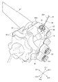
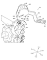
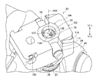
- 3 to 8 are enlarged perspective views showing a portion on the base end side of the operation unit main body 46, respectively.
- the base end surface 46A of the operation unit main body 46 is provided with a cylindrical connection portion 25 in which a take-out port 23 for leading out the base end side of the wire 38 is formed.
- the connecting portion 25 is projected from the proximal end surface 46A in the Y ( ⁇ ) direction, and the proximal end side of the wire 38 is projected from the outlet 23 in the Y ( ⁇ ) direction.
- the wire 38 is projected from a position eccentric with respect to the axial center 25A of the connecting portion 25.
- the wire 38 is provided with a long wire body 38A and a locked portion 39 having an outer shape larger than that of the wire body 38A, which is located on the base end side of the wire body 38A.
- a cylinder is exemplified as the shape of the locked portion 39, but the shape is not limited to this, and any outer shape larger than that of the wire body 38A may be, for example, a sphere.
- wire 38 when used, it mainly refers to the wire body 38A.
- FIG. 4 shows a wire 38 having a longer protrusion length than the wire 38 shown in FIG.
- the wires 38 shown in FIGS. 3 and 4 both have the same length, but the reason why the protruding lengths of the wires 38 having the same length are different is the soft portion 26 (see FIG. 1) or This is due to the state of the curved portion 28.
- the wire fixing mechanism 78 of this example has a configuration in which the wire 38 can be fixed without being affected by the protruding length of the wire 38, and this configuration will be described later.
- the fixing unit 82 is opposed to the locked portion 39 of the wire 38.
- the open end 84A of the cam groove 84 provided in the fixing unit 82 is aligned with the cam pin 86 projecting from the outer peripheral surface of the connecting portion 25.
- the cam groove 84 is formed so as to be inclined from the opening end 84A toward the Y ( ⁇ ) direction.
- the wire 38 is housed inside the fixing unit 82 with the locked portion 39 at the head while advancing the fixing unit 82 toward the connecting portion 25 in the Y (+) direction. To go.
- this operation is referred to as a "wire accommodating operation”.
- the fixing unit is set with the axis 25A (see FIG. 4) eccentric from the wire 38 as the rotation axis.
- the 82 is rotated in the clockwise direction indicated by the arrow B from the state shown in FIG. In this case, it is preferable to rotate the fixing unit 82 by using the sliding lever 80. Then, the fixing unit 82 is pushed in the Y (+) direction by the guide action between the cam groove 84 and the cam pin 86. Then, in the posture of FIG.
- the fixing unit 82 is attached to the operation unit main body 46 via the connection unit 25.
- this operation is referred to as a "rotational mounting operation”. Therefore, the fixed unit 82 is mounted on the operation unit main body 46 through the above-mentioned “wire accommodating operation” and “rotational mounting operation”. The “wire accommodating operation” and the “rotational mounting operation” are executed by one action.
- FIG. 9 is an enlarged perspective view showing a portion of the operation unit main body 46 on the base end side.
- the operation unit main body 46 has a link member 88 connected to the standing operation lever 20.
- the link member 88 is rotatably provided around the rotation axis of the standing operation lever 20 and is rotated in the same direction in conjunction with the rotation operation of the standing operation lever 20.
- An opening 90 is formed in the link member 88, and the sliding lever 80 is operated to stand up via the link member 88 by engaging the claw portion 92 provided on the sliding lever 80 with the opening 90. It is detachably connected to the lever 20.
- the claw portion 92 is provided at the tip (free end) of the cantilever-shaped elastic piece provided on the sliding lever 80, and functions as the lever connecting portion of the present invention.
- the sliding lever 80 is rotatably connected to the fixed unit 82 via a first axis 94 that is selectively switched and a second axis 96 shown by a broken line.
- the sliding lever 80 shown in FIG. 8 when the sliding lever 80 shown in FIG. 8 is pushed down toward the link member 88 in the direction indicated by the arrow C, the sliding lever 80 first rotates with the first axis 94 as the rotation axis. As shown in FIG. 9, it approaches the link member 88. After that, when the above-mentioned pushing-down operation is continued, the sliding lever 80 rotates with the second shaft 96 as the rotation axis, and as shown in FIG. 10, the claw portion 92 engages with the opening 90 (see FIG. 9). It fits.
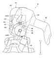
- FIG. 10 is a front view of the operation unit main body 46 as viewed from the X (+) direction side of the operation unit main body 46.
- FIG. 10 shows a state in which the standing operation lever 20 is located at the lodging operation position. That is, the wire fixing mechanism 78 of this example is connected to the standing operation lever 20 located at the lodging operation position via the link member 88. Further, as will be described in detail later, the locked portion 39 (see FIG. 4) of the wire 38 is a fixed unit by undergoing the above-mentioned "wire accommodating operation”, “rotational mounting operation”, and “lever connecting operation”. It is fixed to 82.
- the lever connection operation is performed at the lodging operation position is shown, but the present invention is not limited to this, and the lever connection operation may be performed at a position other than the lodging operation position. For example, the lever connection operation may be performed at the standing operation position, or may be performed between the standing operation position and the lodging operation position.
- FIG. 10 when the posture of the standing table 36 (see FIG. 2) is changed by rotating the standing operation lever 20, the standing operation lever 20 of FIG. 10 located at the lodging operation position is shown in FIG. Rotate in the counterclockwise direction indicated by the arrow U (see FIG. 10) toward the indicated standing operation position. Then, the link member 88 rotates in the counterclockwise direction, the sliding lever 80 connected to the link member 88 moves in the Y ( ⁇ ) direction, and the fixing unit 82 connected to the sliding lever 80 moves in the Y ( ⁇ ) direction. ) Move in the direction. Since the locked portion 39 of the wire 38 (see FIG. 2) is fixed to the fixing unit 82, the wire 38 is pulled in the Y ( ⁇ ) direction by the rotation operation of the standing operation lever 20. As a result, the posture of the standing table 36 connected to the tip of the wire 38 is changed from the lying position in FIG. 2 to the standing position.
- the wire fixing mechanism 78 when the wire fixing mechanism 78 is removed from the operation unit main body 46, the "lever connection operation", the “rotational mounting operation”, and the “wire accommodating operation” may be executed in reverse procedures.
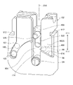
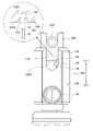
- FIG. 12 is a front view of the fixed unit 82.
- the fixing unit 82 guides the wire catch 100 that detachably locks and fixes the base end side of the wire 38 and the wire catch 100 in the wire axial direction (Y-axis direction) of the wire 38. It has a catch guide 102 and a wire. Further, the wire catch 100 has a catch main body 104 and a fixing member 106.
- the fixing member 106 functions as a fixing portion of the present invention. As will be described in detail later, among the constituent members of the fixed unit 82, the member that moves in the Y-axis direction by the operation of the sliding lever 80 (the lever connecting operation and the driving operation of the standing table 36) is the wire catch 100. Therefore, the catch guide 102 does not move.
- the catch guide 102 is provided with a cylindrical connecting portion 108 having a cam groove 84 at the end on the Y (+) direction side, and this connecting portion 108 is connected to the connecting portion 25 of the operating portion main body 46 (see FIG. 6). Will be done.
- the catch guide 102 has a cap 107 attached to an end portion on the Y ( ⁇ ) direction side.
- the cap 107 has claws 110 and 110 formed on both walls, and the claws 110 and 110 can be detachably attached to and detached from the catch guide 102 by engaging the claws 110 and 110 with the grooves 112 and 112 on both walls of the catch guide 102. It is attached.
- FIG. 13 is a perspective view of a main part when the cap 107 is removed from the catch guide 102 shown in FIG.
- a catch guide groove 114 extending in the wire axial direction is formed in the central portion, and the first shaft 94 is slidably engaged and guided along the catch guide groove 114. ..
- the first shaft 94 is a shaft constituting one of the rotating shafts of the sliding lever 80, and is fixed to the catch body 104.
- the lever bearing hole 80A (see FIG. 14) of the sliding lever 80 is rotatably engaged with the first shaft 94.
- FIG. 14 is a perspective view showing a main part of the sliding lever 80.
- the sliding lever 80 has a pair of plate-shaped portions 120 and 120 that sandwich and hold the fixing unit 82 (see FIG. 5), and a lever body 122 that is integrated with the plate-shaped portions 120 and 120. And have.
- a second shaft 96 which is one of the rotation shafts of the sliding lever 80, is provided on the inner side surfaces of the plate-shaped portions 120 and 120 facing each other, and the second shaft 96 is the catch guide 102 shown in FIG. It is projected toward the surface 102A of. Further, in the plate-shaped portions 120 and 120, cam grooves 124 having a substantially L-shape are formed at positions facing each other, and the pins 126 provided in the fixing member 106 (see FIG. 13) are engaged in the cam grooves 124. It has been combined. The cam groove 124 will be described later.
- a boss 121 is provided on the inner side surfaces of the plate-shaped portions 120 and 120 facing each other, and the boss 121 is projected toward the surface 102A of the catch guide 102 shown in FIG. Further, the surface 102A is formed with a boss hole 103 to which the boss 121 elastically engages. Therefore, when the boss 121 engages with the boss hole 103, the sliding lever 80 is held in the posture shown in FIGS. 5 to 8. Further, by releasing the engagement state of the boss 121 with the boss hole 103, the rotation operation of the sliding lever 80 is permitted.
- a first regulation surface 105 to which the boss 121 shown by the alternate long and short dash line in FIG. 13 can abut is formed.
- the first regulating surface 105 abuts on the boss 121 to regulate the movement of the sliding lever 80 when the pin 126 is present in the first cam groove portion 125A (see FIG. 21) described later in the cam groove 124.
- the first regulation surface 105 enables the sliding lever 80 to rotate about the first shaft 94.
- the first regulation surface 105 is composed of an arcuate surface centered on the first axis 94. As a result, the sliding lever 80 can smoothly rotate around the first shaft 94.
- a second regulation surface 116 is formed on the surface 102A of the catch guide 102.
- the second regulation surface 116 is a surface that can come into contact with the second shaft 96 when the above restriction on the sliding lever 80 by the first regulation surface 105 is released. That is, the first regulation surface 105 is formed only up to a position corresponding to the position where the second axis 96 abuts on the second regulation surface 116, and at the position where the second axis 96 abuts on the second regulation surface 116. The regulation will be lifted.
- the restriction on the sliding lever 80 by the first regulation surface 105 may be released at the same time as the second axis 96 abuts on the second regulation surface 116, or the second axis 96 may be the second regulation surface.
- the second regulating surface 116 abuts on the second shaft 96 to restrict the movement of the sliding lever 80 when the pin 126 is present in the second cam groove portion 125B (see FIG. 21) described later in the cam groove 124. do.
- the second regulation surface 116 allows the sliding lever 80 to rotate about the second axis 96 while moving the second axis 96 along the second regulation surface 116.
- the second regulation surface 116 is formed so as to be inclined in the Y (+) direction from the catch guide groove 114 toward the outside of the catch guide 102.
- the sliding lever 80 rotates with the first axis 94 as the rotation axis.
- the second axis 96 moves from the position on the left side with respect to the second regulated surface 116 toward the second regulated surface 116.
- the regulation of the first axis 94 by the first regulation surface 105 is released, the second axis 96 comes into contact with the second regulation surface 116, and the second regulation surface 116 slides.
- the movement of the moving lever 80 is regulated.
- the sliding lever 80 can rotate about the second axis 96, so that the sliding lever 80 rotates with the second axis 96 as the rotation axis.
- FIG. 15 is a perspective view showing a state immediately before mounting the wire fixing mechanism 78 on the operation unit main body 46.
- FIG. 16 is a cross-sectional view of the fixing unit 82 along the XVI-XVI line of FIG.
- the catch body 104 is orthogonal to the columnar portion 130 and the axis of the columnar portion 130 from the columnar portion 130 (corresponding to the axis center 25A which is the rotation axis of the fixed unit 82). It has a pair of first axes 94, 94 projecting in the direction, and a guide portion 132 projecting from the columnar portion 130 in the Y ( ⁇ ) direction.
- the guide portion 132 is formed with a catch body groove 133 extending in the wire axial direction.
- the catch body groove 133 is provided at a position overlapping the catch guide groove 114, and a pin 126 (see FIG. 13) is inserted.
- the pin 126 is a cam pin that is engaged with the cam groove 124 of the sliding lever 80, and can move freely forward and backward along the catch body groove 133 by being guided by the cam groove 124.
- the cylindrical portion 130 has a locking hole 137 that can be locked through the locked portion 39 (see FIG. 17).
- the locking hole 137 is formed as a through hole penetrating the columnar portion 130 in the Y-axis direction.
- the locking hole 137 is a first hole 134 having a size through which the locked portion 39 can be inserted, and a second hole having a size larger than the outer shape of the wire body 38A and smaller than the outer shape of the locked portion 39. It has holes 136, and the first hole 134 and the second hole 136 have a continuous opening shape.
- the locking hole 137 is provided at a position eccentric from the axis 25A which is the rotation axis of the fixed unit 82, and the first hole 134 and the second hole 136 are provided along the rotation locus centered on the axis 25A. And are formed continuously.
- the amount of eccentricity of the locking hole 137 with respect to the axis 25A is set to be substantially equal to the amount of eccentricity of the wire 38 with respect to the axis 25A shown in FIG.
- the locked portion 39 is accommodated in the first hole 134 during the “wire accommodating operation” (see FIG. 6). Then, the locked portion 39 passes through the first hole 134 and projects outward from the first hole 134 as shown in FIG. Then, at the end of the "wire accommodating operation” (see FIG. 7), the wire 38 protrudes from the first hole 134 in the Y ( ⁇ ) direction as shown in the cross-sectional view of FIG.
- the catch body 104 rotates with the catch guide 102 in the direction of arrow B about the axis 25A, so that the first hole 134 retracts from the wire 38. ..
- the wire 38 is accommodated in the second hole 136 as shown in the cross-sectional view of FIG.
- the locked portion 39 can be locked in the second hole 136.
- FIG. 20 is an explanatory diagram showing an example of the positional relationship between the catch body 104 and the fixing member 106 at the end of the “rotational mounting operation” shown in FIG.
- the fixing member 106 is arranged on the Y ( ⁇ ) direction side with respect to the catch body 104.
- a fixing hole 138 having an opening 135 capable of receiving the locked portion 39 is formed on the end surface 106A on the Y (+) direction side of the fixing member 106.
- the fixing hole 138 is formed at a position facing the second hole 136 shown in FIG. 19 in the Y-axis direction, and has a bottom portion 138A internally engaged with the locked portion 39. Further, the fixing hole 138 has a conical guide surface 139 that tapers from the opening 135 toward the bottom 138A. Although the guide surface 139 is not essential, it is preferable to provide the locked portion 39 in the fixing hole 138 from the viewpoint of smoothly guiding the locked portion 39 to the bottom portion 138A. As shown in FIG. 20, at the end of the "rotational mounting operation" (that is, before the start of the "lever connection operation"), the locked portion 39 is not engaged with the bottom portion 138A and is not engaged with the bottom portion 138A. It is located at a position separated from the Y (+) direction side.
- FIG. 21 is a front view of the wire fixing mechanism 78 at the end of the “rotational mounting operation” shown in FIG. 19, which is a perspective view of the plate-shaped portion 120 of the sliding lever 80.
- the boss 121 is fitted in the boss hole 103, and the second shaft 96 is located on the upper left side in FIG. 21 with respect to the second regulation surface 116.
- the pin 126 is located at the right end 124A of the cam groove 124.
- the cam groove 124 has a shape in which a linear first cam groove portion 125A and a curved second cam groove portion 125B are continuous.
- the first cam groove portion 125A has a function of changing the relative distance between the catch main body 104 and the fixing member 106 by moving the fixing member 106 in the Y-axis direction in cooperation with the pin 126.
- the second cam groove portion 125B has a function of maintaining the relative distance between the catch main body 104 and the fixing member 106 by moving the fixing member 106 in the Y-axis direction integrally with the catch main body 104. ..
- the boss 121 is separated from the boss hole 103 and guided to the first regulation surface 105 as shown in FIG. 22, and the sliding lever 80 Rotates clockwise on FIG. 22 with the first axis 94 as the rotation axis. Then, this rotation causes the pin 126 to move along the first cam groove portion 125A.
- the fixing member 106 moves in the Y (+) direction and approaches the catch body 104. Then, as shown in FIG. 23, the bottom portion 138A of the fixing hole 138 of the fixing member 106 engages with the locked portion 39 in the middle of the “lever connecting operation”.
- the locked state between the locked portion 39 and the second hole 136 is fixed by the fixing member 106, and the locked portion 39 is securely fixed to the fixing unit 82.
- the position of the fixing member 106 shown in FIG. 25 is the fixed position, and the position of the fixing member 106 shown in FIG. 20 is the release position.
- the fixing member 106 can be moved between the fixing position and the releasing position by the rotation operation of the sliding lever 80.
- the inner wall surface of the bottom portion 138A functions as a regulatory surface of the present invention.
- the inner wall surface of the bottom 138A is at least a part of the inner wall surface of the fixing hole 138.
- the second axis 96 is the second regulation.
- the sliding lever 80 rotates clockwise around the second axis 96 while moving along the surface 116.
- the catch body 104 moves in the Y (-) direction via the first shaft 94, and the pin 126 moves along the second cam groove portion 125B, so that the fixing member 106 is the catch body. It moves in the Y (-) direction together with 104.
- the wire 38 pushed in the Y (+) direction is pulled up in the Y ( ⁇ ) direction.
- the "lever connecting operation” ends at the lodging operation position of FIG. 27 in which the sliding lever 80 is connected to the link member 88 (see FIG. 10), and the movement of the catch body 104 and the fixing member 106 stops.
- the base end of the wire 38 is pulled up to the lodging operation position by the standing operation lever 20.
- the pin 126 is located at the left end 124B of the cam groove 124.
- the above is the outline of the operation of the catch body 104 and the fixing member 106.
- the catch body 104 and the fixing member 106 reciprocate along the Y-axis direction in a state of being in contact with each other by the subsequent rotation operation of the standing operation lever 20 (driving operation of the standing table 36) (FIG. 10). And FIG. 11).
- the wire 38 is pushed and pulled to raise and lower the standing table 36.
- the wire fixing mechanism 78 for fixing the proximal end side of the wire 38 is provided, and the wire fixing mechanism 78 is provided on the proximal end side of the wire 38. Since the locking portion 39 is fixed by the fixing member 106 in a state of being locked in the locking hole 137 provided in the wire catch 100, the wire 38 can be reliably fixed to the wire fixing mechanism 78. ..
- the operating range of the wire fixing mechanism 78 is the “wire fixing range” in which the wire catch 100 is operated by the “lever connecting operation” of the sliding lever 80, and the “drive range” in which the wire catch 100 is operated by the rotation operation of the standing operation lever 20. ", And has.
- FIG. 28 is an explanatory diagram showing the above-mentioned “wire fixing range” and “driving range”.
- the wire catch 100 has a long protrusion length of the wire 38 (see XXVIIIA of FIG. 28) and a short protrusion length of the wire 38 (see XXVIIIB of FIG. 28).
- the wire catch 100 executes the locking of the locked portion 39 with respect to the locking hole 137 and the fixing of the locked state between the locked portion 39 and the locking hole 137. Therefore, it is securely fixed to the wire fixing mechanism 78.
- the wire 38 can be reliably fixed regardless of the protruding length of the wire 38.
- the wire catch 100 operates in the "wire fixing range", so that the base end of the wire 38 is tilted by the upright operation lever 20 regardless of the protruding length of the wire 38. Can be pulled up to the position.
- the positional relationship between the position of the standing table 36 and the position of the standing operation lever 20 can be made constant regardless of the protruding length of the wire 38.
- FIG. 29 is a perspective view showing a part of the connection state between the sliding lever 150 constituting the wire fixing mechanism 148 and the fixing unit 152.
- FIG. 30 is a front view of the wire fixing mechanism 148 shown in FIG. 29.
- FIG. 31 is a cross-sectional view of the wire fixing mechanism 148 shown in FIG. 29 to 31 both show the state at the end of the "rotational mounting operation".
- the same components as those in the first embodiment may be designated by the same reference numerals and detailed description thereof may be omitted.
- the fixing member 106 is moved to a fixed position in conjunction with the "lever connecting operation" of the sliding lever 80, and the locked portion 39 is fixed by the fixing member 106.
- the second embodiment has a configuration in which the locked portion 39 is fixed by the fixing member 154 by manually moving the fixing member 154 to the fixing position.
- the fixing member 154 functions as a fixing portion of the present invention.
- the wire fixing mechanism 148 has a fixing member 154, and the fixing member 154 has a substantially cylindrical main body portion 156 and a disk-shaped button portion 158. There is.
- the main body portion 156 is movably mounted on the outer peripheral surface of the catch guide 102 along the Y-axis direction.
- the button portion 158 is a portion pressed by the operator's finger, and as shown in FIG. 31, a cylindrical slide portion 160 is projected from the inner surface of the button portion 158 toward the Y (+) direction. There is.
- the slide portion 160 is movably attached to the end portion of the catch body 162 on the Y ( ⁇ ) direction side along the Y-axis direction. Further, the inner surface of the button portion 158 is provided with a fixing hole 138 that is engaged with the locked portion 39 of the wire 38. Also in the catch body 162 described above, similarly to the catch body 104 shown in FIG. 16, a locking hole 137 having a continuous opening shape between the first hole 134 and the second hole 136 is formed.
- the fixing member 154 is guided by the slide portion 160. Move in the Y (+) direction.
- the locked portion 39 is locked in the second hole 136 (see FIG. 19), and the locked portion 39 is sandwiched between the fixing hole 138 and the catch body 162.
- the fixing member 154 is held at the above-mentioned moved position due to the frictional resistance between the slide portion 160 and the catch body 162.
- the sliding lever 150 rotates clockwise with the first axis 94 as the axis of rotation. Then, as shown in FIG. 35, the second shaft 96 abuts on the second regulating surface 116, and the second regulating surface 116 regulates the movement of the sliding lever 150.
- the rotation axis of the sliding lever 150 moves from the first axis 94 to the outside while the second axis 96 moves toward the outside of the catch body 162 along the second regulation surface 116. It can be switched to 2-axis 96. Then, the sliding lever 150 rotates around the second shaft 96 as a rotation axis, and the fixing member 154 and the catch body 162 integrally move in the Y ( ⁇ ) direction to pull up the wire 38. Then, the sliding lever 150 is connected to the link member 88 (see FIG. 10). Since the operation of raising and lowering the standing table 36 (see FIG. 2) to be performed after that is the same as that of the first embodiment, the description thereof will be omitted.
- the sliding lever 150 when the sliding lever 150 is connected to the link member 88 by executing the "lever connecting operation" before the manual pushing operation of the button portion 158, the wire 38 is connected to the wire fixing mechanism 148. Since it is not fixed, the standing table 36 (see FIG. 2) cannot be raised or lowered.
- the wire fixing mechanism 148 allows a restricted state that regulates the "lever connecting operation” when the fixing member 154 is in the release position, and allows a “lever connecting operation” when the fixing member 154 is in the fixed position. It has an operation control unit 163 that can selectively switch between the allowable state and the allowable state.
- the operation regulating unit 163 has a columnar boss 164, 164 and an arc-shaped groove 166 to which the boss 164, 164 is engaged, as shown in FIG. 29.
- the boss 164 is projected so as to face each other on the inner side surfaces of the plate-shaped portions 120 and 120 of the sliding lever 150 that face each other.
- the groove 166 is formed on the outer peripheral surface of the main body portion 156 of the fixing member 154.
- the boss 164 and the groove 166 are engaged with each other at the release positions shown in FIGS. 29 to 31, and at this time, the wire fixing mechanism 148 is held in a regulated state that regulates the “lever connection operation”. There is. Then, as described above, when the fixing member 154 is moved to the fixed position by manually pushing the button portion 158, the groove 166 moves in the Y (+) direction as shown in FIGS. 32 and 33. By doing so, the engagement with the boss 164 is released. As a result, the wire fixing mechanism 148 is switched to an allowable state that allows the "lever connection operation", and then the "lever connection operation” is executed to connect the sliding lever 150 to the link member 88. ..
- the “lever connecting operation” can be regulated when the fixing member 154 is in the release position, and the fixing member 154 is in the fixed position.
- “lever connection operation” can be allowed.
- the standing table 36 (see FIG. 2) can be reliably laid down by the standing operation lever 20.
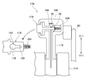
- FIG. 36 is a cross-sectional view showing a main part of the wire fixing mechanism 170 according to the third embodiment.
- the same components as those of the wire fixing mechanism 78 of the first embodiment may be designated by the same reference numerals and detailed description thereof may be omitted.
- the wire fixing mechanism 170 shown in FIG. 36 has a wire catch 172, a catch guide 174, and a sliding lever 80.
- a wire catch 172 is connected to the sliding lever 80.
- the wire catch 172 has a stopper 176.
- the stopper 176 has a locking hole 182 that can be locked by inserting the locked portion 39.
- the locking hole 182 has a semicircular first hole 178 and a long hole-shaped second hole 180 having a continuous opening shape.
- the outer shape of the first hole 178 is formed to be larger than the locked portion 39 which is a sphere.
- the width of the second hole 180 is formed to be larger than the wire diameter but smaller than the locked portion 39.
- the locking hole 182 functions as the locking hole of the present invention.
- the stopper 176 is movably attached to the wire catch 172 via a spring 184 in a direction orthogonal to the wire axial direction (Y-axis direction).
- the stopper 176 functions as a locking member of the present invention.
- the wire catch 172 has a fixed portion 186.
- the fixing portion 186 has a fixing hole 188 with which the locked portion 39 is engaged.
- the fixing hole 188 is formed at a position facing the second hole 180 in the Y-axis direction in FIG. 36.
- the fastener 176 is pushed into the wire catch 172 against the urging force of the spring 184.
- the first hole 178 faces the locked portion 39, so that the locked portion 39 passes through the first hole 178 and engages with the fixing hole 188.
- the position of the stopper 176 at this time corresponds to the insertion position.
- the stopper 176 is returned to the position shown in FIG. 36 by using the urging force of the spring 184.
- the second hole 180 faces the locked portion 39, so that the locked portion 39 and the second hole 180 are locked, and the locked portion 39 and the second hole 180 are locked.
- the state is fixed by the fixing portion 186.
- the position of the stopper 176 at this time corresponds to the locking position.
- the wire fixing mechanism 170 has a wire catch 172, a catch guide 174, and a sliding lever 80, and the wire 38 is engaged.
- the wire catch 172 has a stopper 39
- the wire catch 172 has a stopper 176 in which a locking hole 182 that can be locked by inserting the locked portion 39 is formed, and the locked portion 39 and the locking hole 182. Since it has a fixing portion 186 for fixing the locked state, the wire 38 can be reliably fixed to the wire fixing mechanism 170.
- FIG. 37 is a perspective view of the wire fixing mechanism 190 according to the fourth embodiment.
- the same components as those of the wire fixing mechanism 78 of the first embodiment may be designated by the same reference numerals and detailed description thereof may be omitted.
- the wire fixing mechanism 190 shown in FIG. 37 has a wire catch 192. Although not shown in FIG. 37, the wire fixing mechanism 190 has a catch guide and a sliding lever.
- the wire catch 192 has a stopper 194.
- the stopper 194 has a locking hole 200 that can be locked by inserting the locked portion 39.
- the locking hole 200 has an opening shape in which a rectangular first hole 196 and a long hole-shaped second hole 198 formed narrower than the first hole 196 are continuous.
- the outer shape of the first hole 196 is larger than that of the locked portion 39.
- the width of the second hole 198 is formed to be larger than the wire diameter but smaller than the locked portion 39.
- the locking hole 200 functions as the locking hole of the present invention.
- the stopper 194 has a leaf spring 202 formed by bending into a triangular shape.
- the stopper 194 is attached to the wire catch 192 via a leaf spring 202 in a direction orthogonal to the wire axial direction (Y-axis direction).
- the fastener 194 functions as a locking member of the present invention.
- the wire catch 192 has a fixed portion 204.
- the fixing portion 204 has a fixing hole 206 in which the locked portion 39 is engaged.
- the fixing hole 206 is formed at a position facing the second hole 198 in the Y-axis direction in FIG. 37.
- the fastener 194 is pushed into the wire catch 192 against the urging force of the leaf spring 202. ..
- the first hole 196 faces the locked portion 39, so that the locked portion 39 passes through the first hole 196 and engages with the fixing hole 206.
- the position of the stopper 194 at this time corresponds to the insertion position.
- the stopper 194 is returned to the position shown in FIG. 37 by using the urging force of the leaf spring 202.
- the second hole 198 faces the locked portion 39, so that the locked portion 39 and the second hole 198 are locked, and the locked portion 39 and the second hole 198 are locked.
- the state is fixed by the fixing portion 204.
- the position of the stopper 194 at this time corresponds to the locking position.
- the wire 38 can be reliably fixed to the wire fixing mechanism 190 as in the third embodiment.
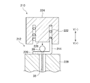
- FIG. 38 is a perspective view of the wire fixing mechanism 210 according to the fifth embodiment
- FIG. 39 is a cross-sectional view of the wire fixing mechanism 210.
- the same components as those of the wire fixing mechanism 78 of the first embodiment may be designated by the same reference numerals and detailed description thereof may be omitted.
- the wire fixing mechanism 210 shown in FIGS. 38 and 39 has a wire catch 212.
- the wire catch 212 has a catch body 228 and a fixing member 224.
- the fixing member 224 functions as a fixing portion of the present invention.
- the wire fixing mechanism 210 has a catch guide and a sliding lever.
- the wire catch 212 has an L-shaped fastener 214.
- a V-shaped groove 216 is formed in the stopper 214.
- the groove 216 has a wide portion 218 on the opening side and a narrow portion 220 on the opposite side to the opening side.
- the wide portion 218 is formed larger than the outer shape of the locked portion 39, while the width of the narrow portion 220 is formed to be larger than the wire diameter but smaller than the locked portion 39.
- the groove 216 functions as a locking hole of the present invention.
- stopper 214 is attached to the fixing member 224 via a spring 222 that urges the stopper 214 in the Y (+) direction.
- the fastener 214 functions as a locking member of the present invention.
- the fixing member 224 has an engaging surface 226 that is engaged with the locked portion 39 of the wire 38.
- the engaging surface 226 is formed at a position facing each other in the Y-axis direction with the narrow portion 220 of the groove 216.
- the engaging surface 226 is a flat surface in FIG. 39, it may have a hole shape similar to that of the fixing hole of the present invention in which an opening capable of accepting the locked portion 39 is formed. In this case, it is preferable that at least a part of the inner wall surface of the hole is configured as a regulating surface.
- This regulation surface is a surface that restricts the movement of the locked portion 39 in a direction orthogonal to the wire axial direction.
- the locked portion 39 comes into contact with the narrow portion 220 of the groove 216 of the fastener 214. Then, when the above-mentioned accommodating operation is continued, the stopper 214 is pushed by the locked portion 39 and swings against the urging force of the spring 222. By this operation, the wide portion 218 of the groove 216 faces the locked portion 39, and the locked portion 39 passes through the groove 216. Immediately after that, the fastener 214 returns to the position shown in FIG. 39 by the urging force of the spring 222. As a result, the locked portion 39 and the narrow portion 220 are locked.
- the fixing member 224 is fixed to the catch body 228 by a fixing means (not shown), and the engaging surface 226 is engaged with the locked portion 39.
- the fixing means include fixing means by screws, fixing means by engagement such as snap fit, and fixing means by press fitting.
- the wire 38 can be reliably fixed to the wire fixing mechanism 210.
- FIG. 40 is a perspective view of the wire fixing mechanism 230 according to the sixth embodiment
- FIG. 41 is a cross-sectional view of the wire fixing mechanism 230.
- the same components as those of the wire fixing mechanism 78 of the first embodiment may be designated by the same reference numerals and detailed description thereof may be omitted.
- the wire fixing mechanism 230 shown in FIGS. 40 and 41 has a wire catch 232. Although not shown in FIGS. 40 and 41, the wire fixing mechanism 230 has a catch guide and a sliding lever.
- a V-shaped groove 234 is formed in the wire catch 232.
- the groove 234 has a wide portion 236 on the opening side and a narrow portion 238 on the side opposite to the opening side.
- the wide portion 236 is formed larger than the outer shape of the locked portion 39, while the width of the narrow portion 238 is formed to be larger than the wire diameter but smaller than the locked portion 39.
- the groove 234 functions as a locking hole of the present invention.
- the wire catch 232 has a fixing portion 240.
- the fixing portion 240 has an engaging surface 242 that is engaged with the locked portion 39.
- the engaging surface 242 is formed at a position facing each other in the Y-axis direction with the narrow portion 238 in FIG. 41.
- the wire catch 232 is inserted into the wire 38 from the direction orthogonal to the wire axial direction (Y-axis direction).
- the locked portion 39 and the narrow portion 238 of the groove 234 are engaged, and the engaging surface 242 engages with the locked portion 39.
- the locked state between the locked portion 39 and the narrowed portion 238 is fixed by the fixed portion 240.
- the wire 38 can be reliably fixed to the wire fixing mechanism 230.
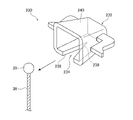
- FIG. 42 is an assembly perspective view of the wire fixing mechanism 250 according to the seventh embodiment.
- the same components as those of the wire fixing mechanism 78 of the first embodiment may be designated by the same reference numerals and detailed description thereof may be omitted.
- the wire fixing mechanism 250 shown in FIG. 42 has a wire catch 252.
- the wire catch 252 has a catch body 258 and a fixing member 262.
- the fixing member 262 functions as a fixing portion of the present invention.
- the wire fixing mechanism 250 has a catch guide and a sliding lever.
- the wire catch 252 has a wedge-shaped fastener 254.
- the stopper 254 is formed with a slit 256 in a direction orthogonal to the wire axial direction (Y-axis direction).
- the width of the slit 256 is formed to be larger than the wire diameter but smaller than the locked portion 39.
- the catch body 258 of the wire catch 252 is formed with a guide groove 260 that guides the stopper 254 in a direction orthogonal to the wire axial direction so as to be movable.
- the fixing member 262 of the wire catch 252 is configured in a cap shape, and the fixing member 262 has an engaging surface 264 engaged with the locked portion 39 of the wire 38 on the inner surface thereof.
- the engaging surface 264 is formed at a position facing the end portion 266 of the slit 256 in the Y-axis direction.
- the fastener 254 is inserted into the wire 38 housed in the catch body 258 from the direction orthogonal to the wire axial direction (Y-axis direction).
- the locked portion 39 and the end portion 266 of the slit 256 are locked.
- the fixing member 262 is fixed to the catch body 258, and the engaging surface 264 comes into contact with the locked portion 39.
- the locked state between the locked portion 39 and the terminal portion 266 is fixed by the fixing member 262.
- the wire 38 can be reliably fixed to the wire fixing mechanism 250.
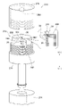
- FIG. 43 is an assembly perspective view of the wire fixing mechanism 270 according to the eighth embodiment.
- the same components as those of the wire fixing mechanism 78 of the first embodiment may be designated by the same reference numerals and detailed description thereof may be omitted.
- the wire fixing mechanism 270 shown in FIG. 43 has a wire catch 272 and a catch guide 274. Further, the wire catch 272 has a catch main body 276 and a fixing member 278. The fixing member 278 functions as a fixing portion of the present invention. Although not shown in FIG. 43, the wire fixing mechanism 270 has a sliding lever.
- the catch body 276 of the wire catch 272 has a stopper 280.
- the stopper 280 is formed with a V-shaped groove 282 in a direction orthogonal to the wire axial direction (Y-axis direction).
- the width of the narrow portion 284 of the groove 282 is formed to be larger than the wire diameter but smaller than the locked portion 39.
- the groove 282 functions as a locking hole of the present invention.
- stopper 280 is formed with a tapered surface 286 that abuts on the locked portion 39 and guides the locked portion 39 toward the narrow portion 284.
- the fixing member 278 of the wire catch 272 is configured in the shape of a cap opened on the catch body 276 side, and the fixing member 278 is engaged with the locked portion 39 of the wire 38 on the inner surface thereof. It has a mating surface 288. In FIG. 43, the engaging surface 288 is formed at a position facing each other in the Y-axis direction with the narrow portion 284 of the groove 282.
- the locked portion 39 of the wire 38 housed in the catch body 276 abuts on the tapered surface 286 of the fastener 280 and is guided by the tapered surface 286. It moves in the Y ( ⁇ ) direction and locks to the narrow portion 284 of the groove 282.
- the fixing member 278 is fixed to the catch body 276 with a screw, and the engaging surface 288 is engaged with the locked portion 39.
- the locked state between the locked portion 39 and the narrowed portion 284 is fixed by the fixing member 278.
- the wire 38 can be reliably fixed to the wire fixing mechanism 270.
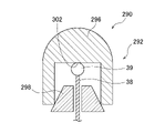
- ⁇ 9th embodiment> 44 is an assembly perspective view of the wire fixing mechanism 290 according to the ninth embodiment, and FIG. 45 is a cross-sectional view of FIG. 44.
- the same components as those of the wire fixing mechanism 78 of the first embodiment may be designated by the same reference numerals and detailed description thereof may be omitted.
- the wire fixing mechanism 290 shown in FIGS. 44 and 45 has a wire catch 292. Further, the wire catch 292 has a catch main body 294 and a fixing member 296. Although not shown in FIGS. 44 and 45, the wire fixing mechanism 290 has a catch guide and a sliding lever.
- the catch body 294 of the wire catch 292 has a collet chuck 298.
- the collet chuck 298 has an opening 300 through which the wire 38 is inserted, and the opening 300 is normally opened larger than the diameter of the locked portion 39.
- the diameter of the opening 300 is reduced by attaching the cap-shaped fixing member 296 to the catch body 294, and the diameter is smaller than the diameter of the locked portion 39.
- the opening 300 functions as a locking hole of the present invention.
- the fixing member 296 has an engaging surface 302 engaged with the locked portion 39 on the inner surface thereof.
- the engaging surface 302 is formed at a position facing the opening 300 in the Y-axis direction in FIG. 45.
- the locked portion 39 of the wire 38 housed in the catch body 294 passes through the opening 300 of the collet chuck 298 and protrudes in the Y ( ⁇ ) direction. do.
- the fixing member 296 is attached to the catch body 294.
- the diameter of the opening 300 is reduced, so that the locked portion 39 and the opening 300 are locked.
- the engaging surface 302 engages with the locked portion 39 the locked state between the locked portion 39 and the opening 300 is fixed by the fixing member 296.
- the wire 38 can be reliably fixed to the wire fixing mechanism 290.
- the catch main body 294 and the fixing member 296 have a tapered mounting surface, so that the above-mentioned locking and fixing can be performed while reducing the diameter of the opening 300. It can be carried out.
- the technique of the present invention is not limited to the duodenal endoscope and can be applied to other endoscopes such as a colonoscope or an enteroscopy. ..
- the present invention may be modified or modified without departing from the gist of the present invention.
- Endoscope 12 Endoscope system 14
- Endoscope processor device 15
- Light source device 15A Processor side connector 16
- Image processing device 18
- Display 20
- Standing operation lever 22
- Hand operation unit 23
- Outlet port 25
- Connection unit 25A
- Axis center 24
- Insertion unit 26
- Flexible part 28
- Curved part 30
- Tip part 32
- Tip part Main body 34
- Cap 34A Opening window 34B
- 34C Bearing 36
- Rotating shaft 37
- Treatment tool channel 38
- Standing operation wire (wire) 39
- Locked part 40
- Wire channel 42
- Air supply water supply tube 44
- Cable insertion channel 45
- Insertion channel 46
- Operation part main body 46A
- Base end surface 48
- Folding prevention pipe 52
- Universal cable 54
- Connector device 57
- Air supply water supply button 58
- Air supply water supply nozzle 59
- Suction button 60
- Treatment tool outlet 61
- Angle knob 64
Landscapes
- Health & Medical Sciences (AREA)
- Life Sciences & Earth Sciences (AREA)
- Surgery (AREA)
- Physics & Mathematics (AREA)
- Engineering & Computer Science (AREA)
- Optics & Photonics (AREA)
- Biomedical Technology (AREA)
- General Health & Medical Sciences (AREA)
- Pathology (AREA)
- Nuclear Medicine, Radiotherapy & Molecular Imaging (AREA)
- Biophysics (AREA)
- Heart & Thoracic Surgery (AREA)
- Medical Informatics (AREA)
- Molecular Biology (AREA)
- Animal Behavior & Ethology (AREA)
- Radiology & Medical Imaging (AREA)
- Public Health (AREA)
- Veterinary Medicine (AREA)
- Mechanical Engineering (AREA)
- Astronomy & Astrophysics (AREA)
- General Physics & Mathematics (AREA)
- Instruments For Viewing The Inside Of Hollow Bodies (AREA)
- Endoscopes (AREA)
Priority Applications (2)
| Application Number | Priority Date | Filing Date | Title |
|---|---|---|---|
| JP2022554134A JPWO2022071564A1 (https=) | 2020-10-02 | 2021-10-01 | |
| US18/191,865 US20230233062A1 (en) | 2020-10-02 | 2023-03-28 | Endoscope |
Applications Claiming Priority (2)
| Application Number | Priority Date | Filing Date | Title |
|---|---|---|---|
| JP2020-167396 | 2020-10-02 | ||
| JP2020167396 | 2020-10-02 |
Related Child Applications (1)
| Application Number | Title | Priority Date | Filing Date |
|---|---|---|---|
| US18/191,865 Continuation US20230233062A1 (en) | 2020-10-02 | 2023-03-28 | Endoscope |
Publications (1)
| Publication Number | Publication Date |
|---|---|
| WO2022071564A1 true WO2022071564A1 (ja) | 2022-04-07 |
Family
ID=80951727
Family Applications (1)
| Application Number | Title | Priority Date | Filing Date |
|---|---|---|---|
| PCT/JP2021/036390 Ceased WO2022071564A1 (ja) | 2020-10-02 | 2021-10-01 | 内視鏡 |
Country Status (3)
| Country | Link |
|---|---|
| US (1) | US20230233062A1 (https=) |
| JP (1) | JPWO2022071564A1 (https=) |
| WO (1) | WO2022071564A1 (https=) |
Families Citing this family (3)
| Publication number | Priority date | Publication date | Assignee | Title |
|---|---|---|---|---|
| US12599289B2 (en) * | 2021-10-25 | 2026-04-14 | Olympus Medical Systems Corp. | Endoscope |
| TWM654199U (zh) * | 2024-01-12 | 2024-04-11 | 晉弘科技股份有限公司 | 轉向關節鋼索固定裝置 |
| CN118873074B (zh) * | 2024-07-31 | 2025-08-12 | 深圳英美达医疗技术有限公司 | 插入部控制装置及内窥镜 |
Citations (2)
| Publication number | Priority date | Publication date | Assignee | Title |
|---|---|---|---|---|
| JPH0478710U (https=) * | 1990-11-21 | 1992-07-09 | ||
| JP2013034547A (ja) * | 2011-08-04 | 2013-02-21 | Olympus Medical Systems Corp | 内視鏡 |
-
2021
- 2021-10-01 WO PCT/JP2021/036390 patent/WO2022071564A1/ja not_active Ceased
- 2021-10-01 JP JP2022554134A patent/JPWO2022071564A1/ja active Pending
-
2023
- 2023-03-28 US US18/191,865 patent/US20230233062A1/en active Pending
Patent Citations (2)
| Publication number | Priority date | Publication date | Assignee | Title |
|---|---|---|---|---|
| JPH0478710U (https=) * | 1990-11-21 | 1992-07-09 | ||
| JP2013034547A (ja) * | 2011-08-04 | 2013-02-21 | Olympus Medical Systems Corp | 内視鏡 |
Also Published As
| Publication number | Publication date |
|---|---|
| US20230233062A1 (en) | 2023-07-27 |
| JPWO2022071564A1 (https=) | 2022-04-07 |
Similar Documents
| Publication | Publication Date | Title |
|---|---|---|
| US6824509B2 (en) | Endoscope | |
| WO2022071564A1 (ja) | 内視鏡 | |
| EP3123963B1 (en) | Endoscope surgical device, surgical tool and guide member | |
| CN111093464A (zh) | 内窥镜 | |
| WO2019163401A1 (ja) | 内視鏡 | |
| WO2022176841A1 (ja) | 内視鏡 | |
| CN115135273B (zh) | 手术器具保持装置以及手术辅助装置 | |
| CN114098595B (zh) | 前端盖拆卸夹具 | |
| WO2019155795A1 (ja) | 内視鏡 | |
| US20200146534A1 (en) | Endoscope | |
| JP7463233B2 (ja) | 内視鏡、及び装着部品 | |
| JP7678817B2 (ja) | 内視鏡 | |
| WO2022071568A1 (ja) | 内視鏡 | |
| CN115175632A (zh) | 手术器具保持装置以及手术辅助装置 | |
| WO2021193693A1 (ja) | 内視鏡 | |
| WO2022071566A1 (ja) | 内視鏡 | |
| WO2022071567A1 (ja) | 内視鏡 | |
| WO2022071565A1 (ja) | 内視鏡 | |
| JP7065093B2 (ja) | 内視鏡 | |
| US11918181B2 (en) | Endoscope | |
| JP7141963B2 (ja) | 内視鏡 | |
| JP2022180048A (ja) | 先端キャップ取外し治具及び内視鏡 | |
| JP2000237118A (ja) | 硬性鏡 | |
| JP7282240B2 (ja) | 内視鏡 | |
| US10398291B2 (en) | Endoscopic surgical device and overtube |
Legal Events
| Date | Code | Title | Description |
|---|---|---|---|
| 121 | Ep: the epo has been informed by wipo that ep was designated in this application |
Ref document number: 21875860 Country of ref document: EP Kind code of ref document: A1 |
|
| ENP | Entry into the national phase |
Ref document number: 2022554134 Country of ref document: JP Kind code of ref document: A |
|
| NENP | Non-entry into the national phase |
Ref country code: DE |
|
| 122 | Ep: pct application non-entry in european phase |
Ref document number: 21875860 Country of ref document: EP Kind code of ref document: A1 |