WO2022071271A1 - 撮像装置、画像処理方法及び画像処理プログラム - Google Patents
撮像装置、画像処理方法及び画像処理プログラム Download PDFInfo
- Publication number
- WO2022071271A1 WO2022071271A1 PCT/JP2021/035523 JP2021035523W WO2022071271A1 WO 2022071271 A1 WO2022071271 A1 WO 2022071271A1 JP 2021035523 W JP2021035523 W JP 2021035523W WO 2022071271 A1 WO2022071271 A1 WO 2022071271A1
- Authority
- WO
- WIPO (PCT)
- Prior art keywords
- subject
- image data
- moving image
- display
- enlarged
- Prior art date
- Legal status (The legal status is an assumption and is not a legal conclusion. Google has not performed a legal analysis and makes no representation as to the accuracy of the status listed.)
- Ceased
Links
Images











Classifications
-
- H—ELECTRICITY
- H04—ELECTRIC COMMUNICATION TECHNIQUE
- H04N—PICTORIAL COMMUNICATION, e.g. TELEVISION
- H04N23/00—Cameras or camera modules comprising electronic image sensors; Control thereof
- H04N23/60—Control of cameras or camera modules
- H04N23/63—Control of cameras or camera modules by using electronic viewfinders
- H04N23/631—Graphical user interfaces [GUI] specially adapted for controlling image capture or setting capture parameters
- H04N23/632—Graphical user interfaces [GUI] specially adapted for controlling image capture or setting capture parameters for displaying or modifying preview images prior to image capturing, e.g. variety of image resolutions or capturing parameters
-
- H—ELECTRICITY
- H04—ELECTRIC COMMUNICATION TECHNIQUE
- H04N—PICTORIAL COMMUNICATION, e.g. TELEVISION
- H04N23/00—Cameras or camera modules comprising electronic image sensors; Control thereof
- H04N23/60—Control of cameras or camera modules
- H04N23/61—Control of cameras or camera modules based on recognised objects
- H04N23/611—Control of cameras or camera modules based on recognised objects where the recognised objects include parts of the human body
-
- G—PHYSICS
- G03—PHOTOGRAPHY; CINEMATOGRAPHY; ANALOGOUS TECHNIQUES USING WAVES OTHER THAN OPTICAL WAVES; ELECTROGRAPHY; HOLOGRAPHY
- G03B—APPARATUS OR ARRANGEMENTS FOR TAKING PHOTOGRAPHS OR FOR PROJECTING OR VIEWING THEM; APPARATUS OR ARRANGEMENTS EMPLOYING ANALOGOUS TECHNIQUES USING WAVES OTHER THAN OPTICAL WAVES; ACCESSORIES THEREFOR
- G03B13/00—Viewfinders; Focusing aids for cameras; Means for focusing for cameras; Autofocus systems for cameras
- G03B13/02—Viewfinders
-
- G—PHYSICS
- G03—PHOTOGRAPHY; CINEMATOGRAPHY; ANALOGOUS TECHNIQUES USING WAVES OTHER THAN OPTICAL WAVES; ELECTROGRAPHY; HOLOGRAPHY
- G03B—APPARATUS OR ARRANGEMENTS FOR TAKING PHOTOGRAPHS OR FOR PROJECTING OR VIEWING THEM; APPARATUS OR ARRANGEMENTS EMPLOYING ANALOGOUS TECHNIQUES USING WAVES OTHER THAN OPTICAL WAVES; ACCESSORIES THEREFOR
- G03B17/00—Details of cameras or camera bodies; Accessories therefor
- G03B17/18—Signals indicating condition of a camera member or suitability of light
-
- H—ELECTRICITY
- H04—ELECTRIC COMMUNICATION TECHNIQUE
- H04N—PICTORIAL COMMUNICATION, e.g. TELEVISION
- H04N23/00—Cameras or camera modules comprising electronic image sensors; Control thereof
- H04N23/60—Control of cameras or camera modules
- H04N23/62—Control of parameters via user interfaces
-
- H—ELECTRICITY
- H04—ELECTRIC COMMUNICATION TECHNIQUE
- H04N—PICTORIAL COMMUNICATION, e.g. TELEVISION
- H04N23/00—Cameras or camera modules comprising electronic image sensors; Control thereof
- H04N23/60—Control of cameras or camera modules
- H04N23/63—Control of cameras or camera modules by using electronic viewfinders
- H04N23/633—Control of cameras or camera modules by using electronic viewfinders for displaying additional information relating to control or operation of the camera
- H04N23/635—Region indicators; Field of view indicators
-
- H—ELECTRICITY
- H04—ELECTRIC COMMUNICATION TECHNIQUE
- H04N—PICTORIAL COMMUNICATION, e.g. TELEVISION
- H04N23/00—Cameras or camera modules comprising electronic image sensors; Control thereof
- H04N23/60—Control of cameras or camera modules
- H04N23/667—Camera operation mode switching, e.g. between still and video, sport and normal or high- and low-resolution modes
-
- H—ELECTRICITY
- H04—ELECTRIC COMMUNICATION TECHNIQUE
- H04N—PICTORIAL COMMUNICATION, e.g. TELEVISION
- H04N23/00—Cameras or camera modules comprising electronic image sensors; Control thereof
- H04N23/60—Control of cameras or camera modules
- H04N23/67—Focus control based on electronic image sensor signals
- H04N23/675—Focus control based on electronic image sensor signals comprising setting of focusing regions
-
- H—ELECTRICITY
- H04—ELECTRIC COMMUNICATION TECHNIQUE
- H04N—PICTORIAL COMMUNICATION, e.g. TELEVISION
- H04N23/00—Cameras or camera modules comprising electronic image sensors; Control thereof
- H04N23/60—Control of cameras or camera modules
- H04N23/69—Control of means for changing angle of the field of view, e.g. optical zoom objectives or electronic zooming
Definitions
- the present invention relates to an image pickup device, an image processing method, and an image processing program, and more particularly to an image pickup device, an image processing method, and an image processing program that outputs moving image data obtained by imaging to a display destination.
- Patent Document 1 describes a technique for automatically switching the display of the live view based on the focus information of the image pickup device when adjusting the focus.
- One embodiment according to the technique of the present disclosure provides an image pickup apparatus, an image processing method, and an image processing program capable of improving operability when manually adjusting the focus.
- An image pickup apparatus equipped with a processor, in which a processor performs a process of extracting a plurality of subjects from moving image data obtained by imaging in a mode of performing focus adjustment, and a specific subject among a plurality of subjects.
- the first moving image data in which the area including the image is enlarged is output to the display destination, and when any of a plurality of subjects changes in the moving image data, the second moving image data in which the areas of the plurality of subjects are enlarged is output.
- the third moving image data in which the area including the selected subject is enlarged is replaced with the second moving image data and displayed to the display destination.
- the processor replaces the second moving image data with the first moving image data and outputs the second moving image data to the display destination, and then if the subject selection is not instructed within the first time, the processor replaces the second moving image data.
- the image pickup device (1) that outputs the first moving image data to the display destination.
- the processor is an image pickup apparatus according to any one of (1) to (3), which further performs a process of accepting the setting of a condition for determining whether or not a change has occurred in the subject.
- the processor further performs a process of modifying the condition for determining whether or not a change has occurred in the subject based on the history of the instruction for selecting the subject, and the image pickup of any one of (1) to (3). Device.
- the condition (6) is the image pickup apparatus of (4) or (5), which includes at least one of an item used for determination and a threshold value used for determination.
- the processor is an image pickup apparatus according to any one of (1) to (6), which determines whether or not a change has occurred in the subject based on a change in at least one item of position, size, and subject distance. ..
- the processor is an image pickup device according to any one of (1) to (7), which outputs an image in which enlarged images of a plurality of subjects are sequentially switched as second moving image data to a display destination.
- the processor performs a process of enclosing the enlarged image in a frame of a different color in the second moving image data and enclosing the corresponding subject in the entire image in a frame of the same color, according to (9).
- Device performs a process of enclosing the enlarged image in a frame of a different color in the second moving image data and enclosing the corresponding subject in the entire image in a frame of the same color, according to (9).
- the processor further performs a process of selecting an object to be enlarged in the second moving image data from a plurality of subjects extracted from the moving image data, and is an image pickup device according to any one of (1) to (10). ..
- the processor further performs a process of accepting the setting of a condition for selecting an object to be enlarged in the second moving image data, the imaging device of (11).
- the processor further performs a process of modifying a condition for selecting an object to be enlarged in the second moving image data based on a history of instructions for selecting a subject (11).
- the processor selects an object to be enlarged in the second moving image data based on the change of at least one item of position, size, and subject distance, and the image pickup of any one of (11) to (13). Device.
- the processor changes when the first moving image data is replaced with the second moving image data when the selection of the subject is not instructed within the first time after outputting the second moving image data to the display destination.
- the image pickup device according to any one of (1) to (13), which excludes the subject determined to have caused the change from the target for detecting the change for the second time after the lapse of the first time.
- the processor In determining whether or not the subject has changed for a plurality of items, the processor has not been instructed to select the subject within the first hour after outputting the second moving image data to the display destination. In this case, the item determined to have changed when the first moving image data is replaced with the second moving image data is excluded from the conditions for detecting the change during the second time after the lapse of the first time.
- the imaging device according to any one of 1) to (15).
- the processor increases the magnification of the subject when magnified and displayed when the depth of field in imaging is set to be narrower than a specific value.
- the processor reduces the enlargement ratio of the subject when the magnified display is performed when the value of the high frequency component in the magnified region is lower than a specific value, whichever is one of (1) to (17).
- Imaging device reduces the enlargement ratio of the subject when the magnified display is performed when the value of the high frequency component in the magnified region is lower than a specific value, whichever is one of (1) to (17).
- the display destination is an external display device connected via a display unit provided in the device main body and / or a connection unit provided in the device main body. Imaging device.
- a plurality of subjects are extracted from the moving image data obtained by imaging, and the first moving image data in which the area including the specific subject in the plurality of subjects is enlarged is output to the display destination, and the plurality of moving image data are present.
- the second moving image data obtained by enlarging the areas of multiple subjects is output to the display destination instead of the first moving image data, and then the selection of the subject is instructed.
- a plurality of subjects are extracted from the moving image data obtained by imaging, and the first moving image data in which the area including the specific subject in the plurality of subjects is enlarged is output to the display destination, and the plurality of moving image data are present.
- the second moving image data obtained by enlarging the areas of multiple subjects is output to the display destination instead of the first moving image data, and then the selection of the subject is instructed.
- An image processing program that causes a computer to perform processing by outputting the third moving image data, which is an enlarged area including the selected subject, to the display destination in place of the second moving image data.
- Block diagram showing an example of the hardware configuration of the image pickup device
- Conceptual diagram of the function to track and magnify a specific subject Diagram showing an example of changes in the subject Figure showing an example of screen display transition Block diagram of the functions realized by the CPU regarding the display control of the live view
- Conceptual diagram showing an example of measuring the amount of change in position
- Conceptual diagram showing an example of measuring the amount of change in size
- Conceptual diagram showing an example of measurement of the amount of change in phase difference
- a diagram showing the relationship between the priority of the subject and the display position on the subject selection screen.
- a flowchart showing an example of the procedure for determining whether or not the subject has changed.
- Flowchart showing the procedure for switching the display of the live view Flowchart showing the procedure for switching the display of the live view Diagram showing an example of live view display transition Diagram showing an example of live view display transition
- the figure which shows an example of the setting screen of the trigger of display switching A block diagram showing an example of a function realized by the CPU when automatically optimizing the conditions for determining whether or not a change has occurred in the subject.
- a flowchart showing a procedure for modifying a condition for determining whether or not a change has occurred in the subject. A table showing an example of the number of switching times and switching rate for each item of change judgment
- the figure which shows an example of the screen which adjusts a threshold setting The figure which shows an example of the subject selection screen displayed by the image pickup apparatus of this embodiment.
- the figure which shows the transformation example of the display of the subject selection screen The figure which shows the further transformation example of the display of a subject selection screen
- a block diagram showing an example of the function realized by the CPU when the display switching based on the change of a specific item is prohibited.
- the figure which shows another example of the screen division in the subject selection screen The figure which shows another example of the screen division in the subject selection screen
- the figure which shows another example of the screen division in the subject selection screen The figure which shows an example of the transition of the screen when the subject of the enlargement candidate is switched and displayed.
- the magnified display function is known as one of the live view functions provided in the image pickup apparatus.
- the live view magnified display function is a function of cutting out a part of the entire image displayed as a normal live view image and enlarging and displaying the entire display area of the live view.
- the live view magnifying feature is used for manual focus adjustment.
- the user manually selects the enlarged position.
- the method of manually selecting the magnifying position by the user has a drawback that the operation becomes complicated.
- an image pickup device that can improve the operability when manually adjusting the focus by using the magnifying display function of the live view will be described.
- FIG. 1 is a block diagram showing an example of a hardware configuration of an image pickup apparatus.
- the image pickup device 10 of the present embodiment is an image pickup device capable of capturing a moving image, and has an image pickup optical system 12, an image pickup unit 14, a display unit 16, a storage unit 18, a connection unit 20, and an operation unit in a device body (not shown). It is equipped with 22, a CPU (Central Processing Unit) 24, a ROM (Read Only Memory) 26, a RAM (Random Access Memory) 28, and the like.
- a CPU Central Processing Unit
- ROM Read Only Memory
- RAM Random Access Memory
- the image pickup optical system 12 includes a plurality of lens groups for forming a subject image on an image pickup element, a diaphragm for adjusting the amount of light, and the like.
- an ND filter (Neutral Density Filter), which is a type of a neutral density filter or a neutral density filter, may be provided in addition to or in place of the diaphragm.
- the focus of the imaging optical system 12 is adjusted by moving a part of the lens group or the whole lens group back and forth along the optical axis.
- the lens group for focus adjustment is an example of a focus lens.
- Actuators such as DC motors, linear motors, stepping motors, and ultrasonic motors are used to drive the lens group for focus adjustment.
- the focus adjustment of the image pickup optical system 12 is possible manually, and the actuator for focus adjustment is driven according to the operation of the operation ring (focus ring) provided on the lens barrel.
- the manual focus adjustment can be performed by using an operation lever or the like in addition to the operation ring.
- the focus adjustment mode When manually adjusting the focus, set the focus adjustment mode (focus mode) to the manual focus mode (Mual Focus Mode).
- the focus adjustment mode includes an autofocus mode (Auto Focus Mode) in addition to the manual focus mode.
- the focus adjustment mode is switched by, for example, a switch (focus mode changeover switch).
- the semi-auto focus mode the focus is adjusted manually, but the focus adjustment status is also monitored by the auto focus adjustment device, and when the object of the manual focus adjustment can be recognized, the focus adjustment is taken over by the auto focus. , And the focus is adjusted by autofocus first, and then fine adjustment is performed by manual adjustment.
- the image pickup unit 14 includes an image pickup element that converts an optical image into an electric signal.
- an image pickup element for example, a CMOS image sensor (CMOS: Complementary Metal Oxide Semiconductor) having a predetermined color filter array (for example, a bayer array or the like), a CCD image sensor (CCD: Charged Coupled Device), or the like is used.
- CMOS Complementary Metal Oxide Semiconductor
- CCD image sensor Charged Coupled Device
- CMOS image sensor including a drive unit, an ADC (Analog to Digital Converter), a signal processing unit, and the like is used as the image pickup element.
- the image sensor is driven by the built-in drive unit to operate.
- the signal of each pixel is converted into a digital signal by the built-in ADC.
- the signal of each pixel is subjected to signal processing such as correlation double sampling processing, gain processing, and correction processing by the built-in signal processing unit.
- the signal processing may be performed on the analog signal of each pixel, or may be performed on the digital signal of each pixel.
- an image pickup device incorporating a phase difference pixel is used as the image pickup element.
- an image sensor with a built-in phase difference pixel it is possible to acquire information on the phase difference of the subject in the screen.
- the direction of the focus of the subject in the screen and the amount of the focus (defocus amount) can be detected from the acquired phase difference information.
- An image sensor incorporating a phase difference pixel and a method for detecting a phase difference using the image sensor are known. Therefore, the description of the details will be omitted.
- Imaging of moving images is performed at a predetermined frame rate.
- the frame rate may be fixed or may be configured to be set by the user to an arbitrary value.
- the display unit 16 is composed of a display such as an LCD (Liquid Crystal Display) and an organic EL display (Organic Light Emitting Display Display, OLED display).
- the image pickup apparatus 10 of the present embodiment is provided with a touch panel on the display surface of the display constituting the display unit 16. That is, the display constituting the display unit 16 is composed of a touch panel display.
- the touch panel may have a so-called in-cell type configuration built in the display unit 16.
- the display unit 16 also includes a display unit 16 in the form of an EVF (Electronic Viewfinder). However, when the display unit 16 is composed of an EVF, the display unit 16 is not provided with a touch panel, but can be provided with, for example, a line-of-sight detection function.
- EVF Electronic Viewfinder
- the display unit 16 displays a live view at the time of imaging.
- the display unit 16 is also used as a user interface when making various settings.
- the storage unit 18 is used for storing captured moving image data (moving image data for recording) and also for storing various data.
- the storage unit 18 is, for example, a semiconductor memory having non-volatile properties such as EEPROM (Electrically Erasable Program Read-only Memory) including a flash memory (Flash Memory), or an SSD (Solid State Drive) containing these semiconductor memories. Consists of.
- the storage unit 18 may have a configuration integrally provided in the main body of the device (a form of a so-called built-in memory) or a detachable configuration (a form of a so-called memory card).
- the connection unit 20 includes a terminal for connecting an external device (for example, an external display device, an external recording device, etc.).
- an external device for example, an external display device, an external recording device, etc.
- HDMI High-Definition Multimedia Interface
- HDMI High-Definition Multimedia Interface
- HDMI High-Definition Multimedia Interface
- the operation unit 22 includes various operation members for operating the image pickup device 10.
- the operation member includes various operation buttons such as a power button, a recording button, a mode dial, and a command dial, as well as a touch panel.
- the operation unit 22 has a focus mode changeover switch for switching the focus mode, a live view button for turning on / off the display of the live view, and a tracking enlarged display during the live view. It is equipped with a tracking magnifying display button that turns the function on and off.
- the focus mode changeover switch is composed of, for example, a slide type switch, and the focus mode (focus adjustment mode) can be selectively switched to an autofocus mode, a manual focus mode, or the like by switching the position of the switch.
- the live view button is composed of, for example, a press-type button, and each time the button is pressed, the display of the live view is switched on and off. The tracking enlarged display function will be described later.
- the CPU 24 is an example of a processor.
- the CPU 24 functions as a control unit, an image processing unit, and the like of the image pickup apparatus 10 by executing a predetermined program.
- the control performed by the CPU 24 includes image control such as automatic exposure and autofocus, display control on the display unit 16, recording control on the storage unit 18, and the like.
- the image processing performed by the CPU 24 includes a processing for generating moving image data for recording and display (for live view), a processing for compressing moving image data for recording, and the like.
- the moving image data for recording and display is generated by subjecting RAW data (raw moving image data output from the imaging unit 14) to predetermined image processing (so-called development processing).
- the image processing here includes offset processing, gamma correction processing, demosaic processing, RGB / YCrCb conversion processing, white balance processing, and the like. Since these are known processes, the details thereof will be omitted.
- the compression process is a process of generating a moving image file in a predetermined compression format.
- a known codec can be adopted as the codec for compression. For example, a codec (MPEG-1, MPEG-2, MPEG-4, etc.) standardized by MPEG (Moving Picture Experts Group) can be adopted.
- the ROM 26 stores a program executed by the CPU 24 and various data necessary for control and the like.
- the memory constituting the ROM 26 includes an EEPROM including a flash memory.
- the RAM 28 is used as a work area when the CPU 24 performs various processes.
- the image pickup apparatus 10 of the present embodiment is provided with a function of tracking and enlarging a specific subject (tracking magnified display function) as one function of the live view.
- the operation unit 22 is provided with a tracking enlargement display button for turning on / off this tracking enlargement display function.
- the tracking enlarged display button is composed of, for example, a press-type button. When the tracking enlarged display button is pressed while the live view is on, the tracking enlarged display function is turned on. If the tracking enlarged display button is pressed while the tracking enlarged display function is on, the tracking enlarged display function is turned off.
- the tracking enlarged display function can be turned on only when the manual focus mode is set. That is, in other focus modes, the tracking enlarged display function is always turned off.
- FIG. 2 is a conceptual diagram of a function of tracking and enlarging a specific subject.
- FIG. 2A shows a normal live view display.
- the entire image is displayed in the entire display area of the live view.
- the whole image means an image displaying the whole image captured by the image pickup unit 14.
- An image in which the entire image is displayed with a predetermined field of view is also included in the overall image here.
- a form in which the entire image is displayed in the entire display area of the live view is referred to as an entire display, if necessary.
- the display area of the live view means an area set as an area for displaying the live view in the entire display area of the display unit 16. Therefore, when the entire display area of the display unit 16 is used as the display area of the live view, the live view image is displayed in the entire display area of the display unit 16.
- the user turns on the tracking enlargement display function and selects the subject A as the object to be enlarged.
- the screen display is switched, and as shown in FIG. 2B, an image obtained by enlarging the subject A by itself at a predetermined enlargement ratio is displayed as a live view image.
- this display form will be referred to as a simple enlargement display, if necessary. That is, a form in which a subject is magnified and displayed by itself is referred to as a single magnified display. After that, a single magnified display is performed following the movement of the subject A. That is, the subject A is always located at the center (almost the center) of the display area of the live view, and the enlarged image is displayed.
- This function is provided as a function that supports manual focus adjustment. Therefore, the subject to be focused is selected as the object to be magnified. By tracking and enlarging the subject to be focused, the user can concentrate on the focusing operation and improve the operability.
- the image pickup apparatus 10 of the present embodiment when a change of a predetermined amount or more is recognized in the subject being imaged, the enlargement is automatically canceled and the screen is switched to the screen for selecting the subject.
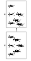
- FIG. 3 is a diagram showing an example of changes in the subject.
- the enlargement is canceled when at least one of the position, the size, and the subject distance changes.
- FIG. 3A shows a captured image at a certain point in time.
- FIG. 3B shows a captured image after a predetermined time has elapsed from the time point of FIG. 3A.
- the positions of the subject A and the subject B are changed. Further, with respect to the subject B, the subject distance is also changing.
- the image captured in this way when at least one of the position, size, and subject distance of the subject being imaged changes by a predetermined amount or more, the enlargement is canceled.
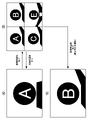
- FIG. 4 is a diagram showing an example of screen display transition.
- FIG. 4A shows an example of the screen display in the case of simple enlargement display.
- the figure shows an example when the subject A is selected as the object to be enlarged.
- FIG. 4B shows an example of a subject selection screen.
- one screen is divided into four equal parts, and an example in which a subject as an enlargement candidate is displayed in each area is shown.
- Candidate subjects are enlarged and displayed in each area.
- the display of each area follows the movement of the subject. That is, in each area, an enlarged image is displayed in which each subject is located at the center (almost the center) of each area.
- the image of the subject enlarged and displayed in each area is an example of the enlarged image.
- the user selects one of the subjects (enlarged images) displayed in each area and selects the target to be enlarged.
- FIG. 4C shows an example of a simple extension display when subject B is selected on the subject selection screen shown in FIG. 4B.
- a subject to be magnified subject B in this example
- the display is switched to a single magnified display, and the selected subject (subject B in this example) is magnified and displayed by itself.
- the simple extension display is performed following the movement of the selected subject (subject B in this example).
- the selection shall be made within the specified time. If the selection is not made within the specified time, the original display is restored. In the example shown in FIG. 4, as shown in FIG. 4A, the screen is switched to a screen in which the subject A is enlarged and displayed by itself.
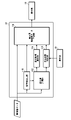
- FIG. 5 is a block diagram of a function realized by the CPU regarding the display control of the live view.
- the CPU 24 functions as a subject extraction unit 110, a change amount measurement unit 112, an enlargement candidate selection unit 114, a display switching determination unit 116, and a display moving image data generation unit 118 with respect to the display of the live view. ..
- Each function is realized by the CPU 24 executing a predetermined program (image processing program).
- the subject extraction unit 110 processes the moving image data obtained by imaging and extracts the subject from the image of each frame.
- the face of a person is extracted as a subject.
- a technique for extracting a person's face from an image a known technique can be adopted.
- FIG. 6 is a diagram showing an example of the extraction result of the subject.
- the extracted subject is surrounded by a bounding box BB, and its position and size are specified.
- the position of the subject is specified, for example, by the coordinate position (x, y) of the center of the bounding box BB or the center of gravity.
- the size of the subject is specified by, for example, the area of the bounding box BB.
- the subject is extracted periodically in a predetermined extraction cycle.
- the change amount measuring unit 112 measures the amount of change in position, size, and phase difference for each subject extracted by the subject extraction unit 110. The measurement is performed periodically at a predetermined measurement cycle. Therefore, the amount of change for each cycle is measured. The measurement cycle is set according to the extraction cycle of the subject.
- FIG. 7 is a block diagram of the functions of the change amount measuring unit.
- the change amount measuring unit 112 has the functions of the position change amount measuring unit 112A, the size change amount measuring unit 112B, and the phase difference change amount measuring unit 112C.
- the position change amount measuring unit 112A measures the amount of change in the position of each subject based on the extraction result of the subject by the subject extraction unit 110.
- FIG. 8 is a conceptual diagram showing an example of measuring the amount of change in position.
- FIG. (B) shows an image taken at a certain measurement time point
- FIG. A (A) shows an image taken at the time of measurement one cycle before.
- the amount of change in the position of the subject is measured as the amount of displacement of the coordinate position. For example, let the coordinate position of the subject at a certain measurement point be (x2, y2). Assuming that the coordinate position at the time of measurement one cycle before the subject is (x1, y1), the amount of change in the position d is calculated by ((x2-x1) 2 + (y2-y1) 2 ) 1/2 . To.
- the size change amount measuring unit 112B measures the amount of change in the size of each subject based on the extraction result of the subject by the subject extraction unit 110.
- FIG. 9 is a conceptual diagram showing an example of measurement of the amount of change in size.
- FIG. (B) shows an image taken at a certain measurement time point
- FIG. A (A) shows an image taken at the time of measurement one cycle before.
- the amount of change in the size of the subject is measured, for example, as the amount of change in the area of the bounding box BB surrounding the subject to be measured.
- S2 be the area of the bounding box BB surrounding the subject to be measured at a certain measurement time point. Assuming that the area of the bounding box BB at the time of measurement one cycle before the subject is S1, the amount of change in size is calculated by S2 / S1.
- the phase difference change amount measuring unit 112C measures the phase difference change amount for each subject extracted by the subject extraction unit 110 at a predetermined measurement cycle. As described above, in the image pickup apparatus 10 of the present embodiment, an image pickup device incorporating a retardation pixel is used. Therefore, by processing the moving image data obtained by imaging, it is possible to acquire the phase difference information for each subject.
- FIG. 10 is a conceptual diagram showing an example of measuring the amount of change in the phase difference.
- FIG. (B) shows an image taken at a certain measurement time point
- FIG. A (A) shows an image taken at the time of measurement one cycle before.
- FIG. 10 shows an example in which the subject to be measured moves in a direction approaching the image pickup apparatus 10.
- the subject distance changes.
- the phase difference also changes.
- the amount of change in the phase difference is calculated by the difference from the phase difference at the time of measurement one cycle before.
- phase difference changes according to the subject distance, so detecting the phase difference is synonymous with detecting the subject distance.
- the enlargement candidate selection unit 114 selects a subject to be displayed on the subject selection screen from a plurality of subjects extracted by the subject extraction unit 110.
- the enlargement candidate selection unit 114 selects a subject (enlargement candidate subject) to be displayed on the subject selection screen based on the information on the amount of change in the position, size, and phase difference of each subject measured by the change amount measurement unit 112. elect.
- four subjects to be enlarged candidates are displayed on the subject selection screen (see FIG. 4B), and four subjects are selected.
- the selection of subjects is performed by calculating the priority of each subject extracted from the image and extracting the top four with high priority.
- the priority degree is calculated by, for example, the following equation.
- Priority w1 x (change in position) + w2 x (change in size) + w3 x (change in phase difference) x w3
- w1, w2, and w3 are preset coefficients. That is, the priority degree of each subject is calculated by multiplying each of the amount of change in position, the amount of change in magnitude, and the amount of change in phase difference by predetermined coefficients w1, w2, and w3 to obtain the sum.
- FIG. 11 is a diagram showing the relationship between the priority of the subject and the display position on the subject selection screen.
- one screen is divided into four equal parts, and the subject as an enlargement candidate is enlarged and displayed in each area.
- the upper left area of the screen is the first display area A1
- the upper right area of the screen is the second display area A2
- the lower left area of the screen is the third display area A3, and the lower right area of the screen is the first.
- 4 Display area A4 The subject with the first priority is displayed in the first display area A1, the subject with the second priority is displayed in the second display area A2, and the subject with the third priority is displayed in the third display area A3.
- the subject having the fourth highest priority is displayed in the fourth display area A4.
- superiority or inferiority is determined according to the following determination rule. That is, the amount of change in position is compared, and the subject having a larger amount of change in position is considered to be superior. If the amount of change in position is also the same, then the amount of change in magnitude is compared, and the subject with the larger amount of change in magnitude is predominant. When the amount of change in magnitude is also the same, the amount of change in phase difference is compared next, and the subject with a larger amount of change in phase difference is considered to be superior. In this way, each item is compared in order to determine superiority or inferiority. In this example, the superiority or inferiority is determined in the order of position, size, and phase difference, but the user may arbitrarily set this order.
- the display switching determination unit 116 displays the live view based on the information on the change amount of the position, size and phase difference of each subject measured by the change amount measurement unit 112 and the operation input information of the operation unit 22. Determine the necessity of switching.
- the information on the amount of change in the position, size, and phase difference of each subject measured by the change amount measuring unit 112 is used to determine whether or not it is necessary to switch to the subject selection screen.
- the operation input information of the operation unit 22 is used to determine whether or not the subject is selected and to specify the selected subject when the screen is switched to the subject selection screen.
- the operation input information of the operation unit 22 is used for determining whether the tracking enlarged display function is on or off.
- Whether or not to switch to the subject selection screen is determined based on the presence or absence of changes in the subject. Whether or not the subject has changed is determined as follows.
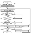
- FIG. 12 is a flowchart showing an example of a procedure for determining whether or not there is a change in the subject.
- the subject extraction unit 110 acquires information on the total number n of subjects extracted from the image (step S11).
- step S12 set the value of k to 1 (step S12).
- step S13 information on the change amount of the position, size, and phase difference of the subject k is acquired (step S13).
- the subject k is a number of the subject numbered in the subject extraction unit 110.
- the amount of change in the position of the subject k is compared with the threshold value (threshold value of the position), and it is determined whether or not it is equal to or greater than the threshold value (step S14).
- the threshold information (position threshold information) is stored in, for example, the ROM 26.
- step S18 When the amount of change in the position of the subject k is equal to or greater than the threshold value (when step S14 is "Yes"), it is determined that the subject has changed (step S18).
- step S15 when the amount of change in the position of the subject k is less than the threshold value (when step S14 is "No"), then the amount of change in the size of the subject k is compared with the threshold value (threshold value of the size), and the threshold value is obtained. It is determined whether or not it is the above (step S15).
- the threshold information size threshold information is stored in, for example, the ROM 26.
- step S18 When the amount of change in the size of the subject k is equal to or greater than the threshold value (when step S15 is "Yes"), it is determined that the subject has changed (step S18).
- step S15 when the amount of change in the size of the subject k is less than the threshold value (when step S15 is "No"), then the amount of change in the phase difference of the subject k is compared with the threshold value (threshold value of the phase difference). It is determined whether or not it is equal to or higher than the threshold value (step S16).
- the threshold information size threshold information is stored in, for example, the ROM 26.
- step S18 When the amount of change in the phase difference of the subject k is equal to or greater than the threshold value (when step S16 is "Yes"), it is determined that the subject has changed (step S18).
- step S17 when the amount of change in the phase difference of the subject k is less than the threshold value (when step S16 is "No"), it is determined that there is no change in the subject (step S17). In this case, it is less than the threshold value in all the items of position, size and phase difference.
- step S20 Since the determination for all the subjects has not been completed, 1 is added to the value of k (step S20), and the determination for the subject with the next number is performed (return to step S13).
- the display switching determination unit 116 determines that switching to the subject selection screen is necessary. On the other hand, if it is determined that there is no change in all the extracted subjects, the display switching determination unit 116 determines that switching to the subject selection screen is unnecessary.
- the screen is switched to the subject selection screen, whether or not the subject to be enlarged is selected is determined based on the operation input of the operation unit 22.
- the subject is selected on the touch panel. That is, by touching the area where the subject to be enlarged is displayed (first display area A1 to fourth display area A4), the subject to be enlarged is selected.
- the display switching determination unit 116 determines that the subject has not been selected. ..
- the specified time for making this selection is an example of the first time.
- the enlargement display function is turned on and off by the tracking enlargement display button provided on the operation unit 22.
- the tracking enlarged display button is composed of, for example, a push-type button, and when the tracking enlarged display function is pressed while the tracking enlarged display function is off, the tracking enlarged display function is turned on. Further, when the tracking enlarged display function is pressed while the tracking enlarged display function is on, the tracking enlarged display function is turned off.
- the tracking enlargement display function When the tracking enlargement display function is turned on, the selection of the target to be enlarged is accepted on the image of the live view, and the selected subject is enlarged and displayed by itself (single enlargement display). In this case, for example, a selectable subject is displayed surrounded by a bounding box (see FIG. 6). Therefore, by selecting the bounding box (touching the subject in the bounding box), the object to be enlarged is selected.
- 13 and 14 are flowcharts showing a procedure for switching the display of the live view.
- Live view can be turned on and off by operating the live view button.
- step S32 the entire display is performed as the live view (step S32). That is, the image captured by the imaging unit 14 is displayed as it is (see FIG. 2A).
- the tracking magnifying display function can be turned on and off by operating the tracking magnifying display button.
- step S37 it is determined whether the live view is on or off (step S37).
- step S37 it is determined whether the live view is on or off (step S37).
- step S37 the display of the live view is turned off (when step S37 is "Yes"), the display of the live view ends.
- step S32 the entire display is continued (step S32).
- step S33 when the tracking enlargement display function is on (in the case of "Yes"), the screen transitions to the enlargement target selection screen (step S34).
- the selection screen here, the subject that can be selected in the live view image of the entire display is displayed by being surrounded by a bounding box (see FIG. 6).
- step S35 it is determined whether or not the enlargement target is selected.
- the target is selected via the touch panel.
- the user touches the subject in the bounding box displayed on the full display screen to select the target to be enlarged.
- step S36 When there is no target selection (when step S35 is “No"), it is determined whether the tracking enlargement display function is on or off (step S36). When the tracking enlarged display function is off (when step S36 is “Yes”), it is determined whether the live view display is on or off (step S37). When the display of the live view is turned off (when step S37 is “Yes”), the display of the live view ends. On the other hand, when the display of the live view is on (when step S37 is "No"), the display can be switched to the normal full display (step S32). That is, it is switched to the whole display in the state where the bounding box is not displayed.
- step S35 when the target is selected (in the case of "Yes"), the selected subject is switched to a single enlarged display (single-enlarged display) (see FIG. 2B) (step S41).
- step S42 when the display is switched to the simple extension display, it is determined whether or not the subject has changed.
- step S42 determines whether the tracking enlargement display function is on or off (step S46).
- step S37 it is determined whether the live view display is on or off (step S37).
- step S37 the display of the live view ends.
- step S32 the display of the live view is on
- step S41 When the tracking enlargement display function is on (when step S46 is "No"), as shown in FIG. 14, single enlargement display is continued for the same subject (step S41).
- step S42 if there is a change in the subject (in the case of "Yes"), the simple extension display is switched to the subject selection screen (step S43).
- the subject selection screen As described above, on the subject selection screen, the subject that is a candidate for enlargement is enlarged and displayed in each display area of the screen divided into four equal parts (see FIG. 4B).
- step S44 it is determined whether or not the target to be enlarged is selected.
- the user touches the display area in which the subject to be enlarged is displayed, and selects the subject to be enlarged. By this selection operation, the change of the target to be expanded is instructed.
- the subject that was displayed in simple extension is included in the candidate image, if the subject that was displayed in simple extension is selected, the subject is not substantially changed, but it is included in the change instruction here. It shall be.
- step S44 When the subject is selected on the subject selection screen (when step S44 is "Yes"), the selected subject can be switched to a single enlarged display (single-enlarged display) (see FIG. 4 (C)). (Step S41).
- step S44 when there is no subject selection (when step S44 is "No"), it is determined whether or not the specified time has elapsed since the screen was switched to the subject selection screen (step S45). If the specified time has not elapsed, the subject selection screen is continued (step S43).
- step S44 determines whether the tracking enlargement display function is on or off.
- step S46 determines whether the tracking enlarged display function is on or off.
- the subject selection screen can be switched to the original single enlarged display (step S41). That is, the subject that was enlarged and displayed before switching to the subject selection screen can be switched to the enlarged display by itself.
- the screen automatically transitions to the subject selection screen. Then, when the subject is selected within the specified time on the subject selection screen, the selected subject is displayed in a simple extension. On the other hand, if the subject is not selected within the specified time, the original single-enlarged display is restored.
- the display is automatically switched in this way, the user can concentrate on the focus adjustment operation even when manually adjusting the focus. This can improve the operability when manually adjusting the focus.
- the display moving image data generation unit 118 generates display moving image data to be output to the display unit 16 based on the display switching determination result by the display switching determination unit 116.
- the moving image data for display includes moving image data for whole display, moving image data for single-enlarged display, and moving image data for a subject selection screen in the case of single-enlarged display. Further, the moving image data for the subject selection screen includes moving image data for initial selection and moving image data for switching the subject.
- the moving image data for initial selection is moving image data to be displayed when the tracking enlarged display function is turned on. That is, it is moving image data for selecting a subject to be displayed in a simple extension first.
- this moving image data is generated as an image in which a selectable subject is surrounded by a bounding box in the image of the entire display (see FIG. 6).
- the moving image data for switching the subject is moving image data to be displayed when the subject being imaged changes by a predetermined amount or more during the simple extension display.
- this moving image data divides one screen into four equal parts, and an image is generated in which a subject selected as an enlargement candidate is enlarged and displayed in each display area (FIGS. 4B and 11). reference).
- the moving image data for switching the subject is an example of the second moving image data, and constitutes the moving image data in which the areas of a plurality of subjects are enlarged respectively.
- the moving image data for simple enlargement display before switching to the moving image data for switching the subject is an example of the first moving image data, and the moving image data in which the area including the specific subject in the plurality of subjects is enlarged. To configure.
- the moving image data for simple enlargement display after the subject is switched is an example of the third moving image data, and constitutes the moving image data in which the area including the subject selected as the enlargement target is enlarged. ..
- FIG. 15 (A) When the live view display is turned on, first, as shown in FIG. 15 (A), the entire display is performed.
- the tracking enlargement display function is turned on during this whole display, the screen transitions to the selection screen of the subject to be displayed in a single enlargement as shown in FIG. 15B.
- the user selects a subject to be displayed in a simple extension on the subject selection screen.
- the subject selected here is an example of a specific subject. The selection is made by touching the target on the screen.
- FIGS. 15 (C) (and 16 (A) That is, it is displayed in a simple enlargement.
- the figure shows an example when the subject A is selected. After that, a single magnified display of the selected subject is performed.
- the moving image data displayed in a simple extension is an example of the first moving image data.
- the screen switches to the subject selection screen as shown in FIG. 16B.
- the subject selection screen four subjects that are candidates for enlargement are enlarged and displayed in each display area divided into four equal parts.
- the display in each display area follows the movement of the subject. That is, in each display area, an enlarged image is displayed in which each subject is located at the center (almost center) of each display area.
- the moving image data for the subject selection screen is an example of the second moving image data.
- the user selects a subject to be displayed in a simple extension on this subject selection screen.
- the selection is made by touching the target on the screen.
- the change of the target is instructed.
- the selected subject is displayed in a simple extension as shown in FIG. 16 (C).
- the figure shows an example in which the subject B (the subject in the upper right display area of the subject selection screen) is selected. After that, a single magnified display of the selected subject is performed.
- the simple enlarged and displayed moving image data after the change is an example of the third moving image data.
- the change of the subject being imaged is measured at a predetermined measurement cycle during the simple extension display, and when there is a change of a predetermined amount or more, the subject is selected as shown in FIG. 16 (B). Switch to the screen.
- the screen when a specific subject is tracked and enlarged and displayed, if there is a change of a predetermined amount or more in the subject being imaged, the screen automatically transitions to the subject selection screen. do. Then, when a subject is selected on the subject selection screen, the selected subject is displayed in a simple extension. On the other hand, if the specified time elapses without selecting the subject on the subject selection screen, the display returns to the original simple extension display. This allows the user to focus on the focus adjustment operation, even when manually adjusting the focus.
- the image pickup apparatus of the present embodiment when switching the display from the simple extension display to the subject selection screen, a change in the position, size, and phase difference of the subject during imaging is used as a trigger.
- the image pickup apparatus of the present embodiment has a configuration in which the user can arbitrarily set a change in the subject as a trigger for switching the display. That is, the configuration is such that the user can arbitrarily set a condition for determining whether or not a change has occurred in the subject. For example, a configuration that switches the display from the single-enlarged display to the subject selection screen using only the change in position as a trigger, or a configuration that switches the display from the single-enlarged display to the subject selection screen using only the change in position and size as a trigger. Or, make it a configuration that can be set arbitrarily by the user.
- the trigger for switching the display is set on a predetermined setting screen.
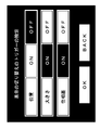
- FIG. 17 is a diagram showing an example of a setting screen for a trigger for switching the display.
- This setting screen is called from the menu screen, for example.
- "ON” and “OFF” buttons are displayed for each item of "position”, "size” and “phase difference”.
- the “ON” and “OFF” buttons are selectively selected.
- the button with a white background is the selected button. Therefore, in the example shown in the figure, the "position” item is set to “ON”, the “size” item is set to “OFF”, and the “phase difference” item is set to "OFF”. In this case, only the change in position is used as a trigger to switch the display from the simple extension display to the subject selection screen.
- the CPU 24 accepts a setting change based on an operation input from the operation unit 22 (touch panel).
- the set information is stored in the storage unit 18.
- the display switching determination unit 116 determines whether or not the subject has changed according to the set information, and determines whether or not the subject needs to be switched to the selection screen. For example, when only the position item is turned on, in the flowchart shown in FIG. 12, the process of step S15 (process of determining whether or not the amount of change in size is equal to or greater than the threshold value) and the process of step S16 (position). The process of determining whether or not the amount of change in the phase difference is equal to or greater than the threshold value) is skipped.
- the change of the subject As the change of the subject, the change of the position, the change of the size, and the change of the phase difference (subject distance) are measured. It may be configured to measure the change of.
- the position, size and phase difference (subject distance) of the subject changes by a predetermined amount or more. It is also possible to combine them to determine whether or not the subject has changed. For example, when the amount of change in position is equal to or greater than the threshold value and the amount of change in magnitude is equal to or greater than the threshold value, it can be determined that there is a change in the subject.
- the image pickup apparatus of the second embodiment is configured such that the user can arbitrarily set conditions for determining whether or not a change has occurred in the subject.
- the determination conditions are automatically optimized based on the user's selection tendency in the past. For example, if the display is switched multiple times based on the change in position and the subject is never selected (switching the subject), the user does not want to switch the display based on the change in position. I can think of it. Therefore, in this case, the setting is set so that the change in the subject is not detected based on the change in the position. This makes it possible to prevent unnecessary display switching and further improve operability.
- a configuration for automatically optimizing the determination conditions based on the user's selection tendency in the past will be described.
- FIG. 18 is a block diagram showing an example of a function realized by the CPU when the conditions for determining whether or not a change has occurred in the subject are automatically optimized.
- the CPU 24 further functions as a selection result recording unit 120 and a determination condition correction unit 122.
- the selection result recording unit 120 records in the storage unit 18 the selection result of the subject when the simple enlargement display is switched to the subject selection screen.
- the selection result is recorded in association with the information of the item of the change of the subject that triggered the switching of the display and the information of the presence / absence of selection.
- the selection result is recorded in the storage unit 18 as selection history data.
- the selection history data is updated every time the subject selection screen is displayed.
- the determination condition correction unit 122 corrects the conditions for determining whether or not a change has occurred in the subject based on the selection history data.
- the modification is made, for example, as follows. That is, the switching rate R of the subject is calculated, and the items for which the switching rate R of the subject is equal to or less than the threshold value are excluded from the conditions for determining whether or not the subject has changed.
- FIG. 19 is a flowchart showing a procedure for modifying conditions for determining whether or not a change has occurred in the subject.
- the condition for determining that a change has occurred in the subject is that at least one change amount of the position, the magnitude, and the phase difference is equal to or more than the threshold value.
- the position item is the first item of the change determination
- the size item is the second item of the change determination
- the phase difference item is the third item of the change determination.
- the variable i is set to 0 (step S51).
- 1 is added to the value of i (step S52).
- the number of switching times is the number of times (total number) switching from the simple extension display to the subject selection screen based on the i-th item of the determination of change. If the number of switchings is less than the threshold (threshold of the number of switchings), it is excluded from the correction target this time. That is, in this case, it is determined that sufficient data has not been obtained to grasp the selection tendency, and the data is excluded from the correction target. If the number of switchings is less than the threshold value (when step S54 is "No"), the process proceeds to step S57. For example, when the threshold value of the number of switching times is set to 15, and the number of switching times of the i-th item of the change determination is less than 15 times, it is excluded from the current correction target.
- step S54 when the number of switchings is equal to or greater than the threshold value (when step S54 is “Yes”), it is then determined whether or not the switching rate R is equal to or less than the threshold value.
- the switching rate R is equal to or less than the threshold value (threshold value of the switching rate R) (when step S55 is “Yes”), the i-th item is excluded from the condition for determining whether or not the subject has changed (step S56). That is, in this case, since the subject is not selected (switched) even though the display is switched, it is excluded from the condition for determining whether or not the subject has changed.
- the change determination is performed.
- the i item is excluded from the conditions for determining whether or not the subject has changed.
- j is the total number of determination items.
- the processing for all items is completed, the processing for modifying the conditions for determining whether or not the subject has changed is completed.
- FIG. 20 is a table showing an example of the number of switching times and the switching rate for each item of determination of change.
- the figure shows an example of switching from a simple extension display to a subject selection screen based on changes in the position, size, and phase difference of the subject.
- the number of times the display is switched is 30 times, and the rate at which the subject is selected (switched) when the display is switched based on the change in position.
- (Switching rate) is 0%.
- the rate at which the subject is selected (switched) when the display is switched 10 times based on the change in phase difference switching number
- the display is switched based on the change in phase difference (switching rate).
- the phase difference is excluded from the correction target because the number of switching times is less than the threshold value for the number of switching times. That is, it is used as it is as a condition for determination.
- the position and size are subject to correction because the number of switchings exceeds the threshold for the number of switchings.
- the size since the switching rate exceeds the threshold value of the switching rate, it is used as it is as a condition for determination. On the other hand, since the switching rate is equal to or less than the threshold value of the switching rate, the position is excluded from the condition for determining whether or not the subject has changed.
- the determination condition correction unit 122 corrects the condition for determining whether or not there is a change in the subject based on the switching rate R calculated from the history of past selection.
- the information of the modified condition is stored in the storage unit 18.
- the display switching determination unit 116 determines whether or not the subject has changed according to the information of the conditions recorded in the storage unit 18, and determines whether or not the subject needs to be switched to the selection screen.
- the conditions for determining the presence or absence of a change in the subject are automatically optimized. This makes it possible to prevent unnecessary display switching. Moreover, since the setting is automatically performed, convenience can be improved.
- the image pickup apparatus of the present embodiment is configured such that the user can adjust the threshold value used when determining whether or not a change has occurred in the subject. That is, the configuration is such that the user can freely raise or lower the threshold setting.
- the image pickup apparatus of the present embodiment is configured to perform this adjustment on a predetermined setting screen.
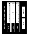
- FIG. 21 is a diagram showing an example of a screen for adjusting the threshold setting.
- the figure shows an example in which the setting of the threshold value of each item of the position, size, and phase difference of the subject is adjusted as the setting of the change characteristic.
- This setting screen is called from, for example, a menu screen.
- levers for adjusting the characteristics of change are individually displayed for each item of "position", "size”, and "phase difference".
- the adjustment lever is configured to be adjustable in five levels on the plus side and the minus side with "0" as the center. Setting the lever to the “0" position sets the threshold to the default value. When the lever is moved from the “0” position to the plus side, the threshold value is gradually increased by a predetermined amount of change. On the other hand, when the lever is moved from the “0” position to the minus side, the threshold value is gradually lowered by a predetermined amount of change.
- the set information is stored in the storage unit 18.
- the display switching determination unit 116 determines whether or not the subject has changed according to the set information, and determines whether or not the subject needs to be switched to the selection screen.
- the display can be appropriately switched according to the imaging scene or the like. This makes it possible to further improve the operability.
- the threshold value may be automatically adjusted as in the image pickup apparatus of the third embodiment. ..
- the switching rate may be calculated individually for each item, and the threshold value may be increased by a predetermined amount for items whose switching rate is equal to or less than the threshold value (threshold value of the switching rate).
- the threshold value can be changed according to the switching rate. For example, the threshold value can be increased as the switching rate decreases.
- the entire image is displayed in one of the display areas divided into four equal parts.
- the whole image is an image displaying the whole image captured by the imaging unit 14, and is an image displayed during a normal live view.
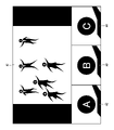
- FIG. 22 is a diagram showing an example of a subject selection screen displayed by the image pickup apparatus of the present embodiment. The figure shows an example when one screen is divided into four equal parts.
- the entire image is displayed in the fourth display area A4 at the lower right on the screen divided into four equal parts.
- the expansion candidate selection unit 114 three subjects are selected as expansion candidate subjects in descending order of priority.
- the subject with the first priority is displayed in the first display area A1
- the subject with the second priority is displayed in the second display area A2
- the subject with the third priority is the third. It is displayed in the display area A3.
- the display moving image data generation unit 118 generates the moving image data having the configuration shown in FIG. 21 as the moving image data for subject switching (moving image data for the subject selection screen).
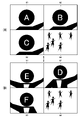
- FIG. 23 is a diagram showing a modified example of the display of the subject selection screen.
- the subjects displayed in the display areas A1 to A3 are surrounded by frames f1 to f3 so that they can be distinguished in the entire image.
- the subject A, the subject B, and the subject C in the entire image are selected as enlargement candidates and are enlarged and displayed in the display areas A1 to A3, respectively.
- the subject A, the subject B, and the subject C are displayed surrounded by frames f1 to f3, respectively.
- Each frame f1 to f3 is displayed in the same range as the range enlarged and displayed in each display area A1 to A3.
- each display area A1 to A3 is further surrounded by frames F1 to F3.
- Each frame F1 to F3 is displayed in a different color.
- the frames f1 to f3 displayed in the entire image are also displayed in different colors.
- the colors of the frames f1 to f3 are the same as the colors of the frames F1 to F3 of the corresponding display areas A1 to A3.
- the color of the frame F1 surrounding the first display area A1 is red
- the color of the frame F2 surrounding the second display area A2 is blue
- the color of the frame F3 surrounding the third display area A3 is yellow.
- the color of the frame f1 surrounding the subject to be displayed in the first display area A1 (subject A in the case of the example of FIG. 23) is red. Further, the color of the frame f2 surrounding the subject to be displayed in the second display area A2 (subject B in the case of the example of FIG. 23) is blue. Further, the color of the frame f3 surrounding the subject to be displayed in the third display area A3 (subject C in the case of the example of FIG. 23) is yellow. In the whole image, the subject surrounded by the frames f1 to f3 (subjects A to C in the case of the example of FIG. 23) is an example of the corresponding subject.
- FIG. 24 is a diagram showing a further modification example of the display of the subject selection screen.
- the color of the frame fx is different from the color of the frames f1 to f3 that surround the subject displayed in the display areas A1 to A3. For example, black.
- the subject A, the subject B, and the subject C are the subjects displayed in the display areas A1 to A3, and the subject D, the subject E, and the subject F are not displayed in the display areas A1 to A3.
- the subject A, the subject B, and the subject C are displayed surrounded by frames f1 to f3 having the same color as the frames F1 to F3 surrounding the corresponding display areas A1 to A3, respectively.
- the subject D, the subject E, and the subject F are displayed surrounded by a frame fx having a color (for example, black) different from the frames f1 to f3.
- the subject can be selected even in the entire image.
- the positions surrounded by the frames f1 to f3 and fx are touched to select a subject to be displayed in a single enlargement.
- the convenience and operability can be further improved by configuring the subject so that the subject can be selected from the entire image.
- the frames f1 to f3 surrounding each subject in the entire image are displayed in the same range as the range enlarged and displayed in each display area A1 to A3. ..
- the display range (size) of the frames f to f3 does not necessarily have to be the same as the range enlarged and displayed in the display areas A1 to A3. Any form may be used as long as it can be visually recognized that the subject is selected as an enlargement candidate.
- the image pickup apparatus of the present embodiment is configured so that the user can manually switch the display from the simple enlargement display to the subject selection screen. That is, in the above embodiment, the display is automatically switched from the simple extension display to the subject selection screen, but in the image pickup apparatus of the present embodiment, the display can be manually switched. Thereby, convenience and operability can be further improved.
- the CPU 24 switches the display from the simple extension display to the subject selection screen in response to the switching instruction from the operation unit 22.
- the operation unit 22 is provided with a dedicated button for the switching instruction, and the operation of the button is used.
- the user may manually switch the display from the subject selection screen to the simple extension display.
- the CPU 24 switches the display from the subject selection screen to the simple extension display in response to the switching instruction from the operation unit 22.
- the single-enlarged display here is performed on the subject that was displayed in a simple-enlarged manner before switching to the subject selection screen. That is, it returns to the original simple enlargement display.
- a predetermined priority is calculated for each subject extracted from the image based on the change amount of the position, size, and phase difference of the subject, and the calculated priority is in descending order.
- the structure is such that the subject to be a candidate for enlargement is selected.
- the image pickup apparatus of the present embodiment is configured so that the user can set the conditions for calculating the priority degree, that is, the selection conditions for the subject to be the enlargement candidate. Specifically, in the formula for calculating the priority degree, the coefficients w1, w2 and w3 can be adjusted by the user within a predetermined range. The image pickup apparatus of the present embodiment is configured to perform this adjustment on a predetermined setting screen.
- FIG. 25 is a diagram showing an example of a screen for adjusting the coefficient of the calculation formula for calculating the priority.
- the figure shows an example in which the coefficients of each item of the position, size, and phase difference of the subject are adjusted as the setting of the selection characteristic of the subject to be the enlargement candidate.
- This setting screen is called from, for example, a menu screen.
- levers for adjusting the selection characteristics are individually displayed for each item of "position”, "size”, and "phase difference".
- the adjusting lever is configured to be adjustable stepwise in the range of "0" to "10".
- the coefficient value is set to 0.
- the coefficient is gradually raised at a predetermined rate of change.
- the lever is set to the maximum value at the "10" position.
- the lever is set to the "10" position, and for the "size” item, the lever is set to the "5" position, and the "phase difference” is set.
- the lever is set to the "0" position.
- enlargement candidates are selected based on the position and size of the subject, and the phase difference is excluded from the judgment target.
- the position is more important than the size.
- the set information (information of coefficients w1 to w3) is stored in the storage unit 18.
- the enlargement candidate selection unit 114 calculates the priority degree according to the set information and selects the subject to be the enlargement candidate.
- the user can set the conditions for calculating the priority degree (conditions for selecting the subject to be the enlargement candidate), so that the subject according to the user's intention can be selected as the enlargement candidate.
- the conditions for calculating the priority degree conditions for selecting the subject to be the enlargement candidate
- the image pickup apparatus of the seventh embodiment is configured such that the user manually sets the conditions for calculating the priority degree.
- the conditions for calculating the priority degree are automatically set based on the user's past selection tendency of the subject. That is, the values of the coefficients w1 to w3 are automatically optimized.
- the values of the coefficients w1 to w3 are set according to the switching rate. Specifically, it is set that the value of the coefficient of each item increases as the switching rate for each item increases.
- a high switching rate means that the subject is often selected due to changes in the item. Therefore, in this case, the coefficient is set to a large value.
- a low switching rate means that the subject is rarely selected due to a change in the item. Therefore, in this case, the coefficient is set to a small value.
- the image pickup apparatus of the present embodiment when the subject is not selected and the original single-enlarged display is restored, switching of the display under the same conditions is prohibited for a predetermined time thereafter. For example, when the screen is switched from the simple extension display to the subject selection screen based on the change in position, if the subject is not selected within the specified time, after returning to the simple extension display, the position is set for a predetermined time. Switching the display based on changes is prohibited.
- a configuration for carrying out this process will be described.
- FIG. 26 is a block diagram showing an example of a function realized by the CPU when switching of the display based on a change of a specific item is prohibited.
- the CPU 24 further functions as a determination item setting unit 130 in order to prohibit switching of the display based on a change in a specific item when the subject is not selected.
- the determination item setting unit 130 individually sets on / off of the item used for determining whether or not the subject has changed in the display switching determination unit 116 based on the determination result of the display switching determination unit 116. For example, for each item, the judgment use flag is set to "1" when it is used for judgment, and the judgment use flag is set to "0" when it is not used for judgment.
- the determination use flag is usually set to "1" and, in certain cases, to "0". The specific case is the case where the subject is not selected. In this case, the determination use flag is set to "0" for the item that triggered the switching of the display, that is, the item for which the change of the threshold value or more is measured.
- the judgment about the position is used.
- the flag is set to "0".
- the judgment use flag is returned to 1 after a predetermined stop time has elapsed.
- the stop time is an example of the second time.
- the display switching determination unit 116 determines whether or not there is a change in the subject based on the determination use flag set by the determination item setting unit 130, and determines whether or not the live view display should be switched. Specifically, based on the change of the item in which the determination use flag is set to "1", the presence or absence of the change of the subject is determined, and the necessity of switching the display of the live view is determined. For example, at a certain judgment timing, it is assumed that the judgment use flag for the position is set to "0", the judgment use flag for the size is set to "1", and the judgment use flag for the phase difference is set to "1". In this case, the determination of the presence or absence of the change of the subject based on the change of the position is excluded, and the presence or absence of the change of the subject is determined only based on the presence or absence of the change of the magnitude and the phase difference.
- the judgment use flag is set to the predetermined stop time after returning to the simple extension display for the item that triggered the display switching when the subject is not selected on the subject selection screen.
- the interval is set to "0". While the determination use flag is "0", the item is excluded from the determination of whether or not the subject has changed. That is, switching of the display based on the change is prohibited.
- the item that triggers the display switching is excluded from the target of the determination of whether or not the subject has changed for a predetermined stop time.
- the subject that triggered the display switching that is, the subject that is determined to have changed, is excluded from the target of determination of the predetermined stop time and presence / absence of change. It can also be.
- the display can be switched according to the user's intention by prohibiting the switching of the display caused by the subject.
- the CPU 24 sets, for example, a judgment use flag for each subject.
- the judgment use flag is a predetermined stop time after returning to the simple extension display for the subject that triggered the display switching, that is, the subject that is judged to have changed when the subject is not selected. Is set to "0" during the period.
- the enlargement ratio of the image at the time of simple enlargement display may be a fixed value or may be a configuration that can be arbitrarily changed by the user. Further, it may be configured to be automatically changed according to the imaging conditions and the like.
- a configuration that automatically changes the enlargement ratio for example, a configuration that changes the enlargement ratio according to the depth of field at the time of imaging can be adopted.
- the enlargement ratio is increased. If the depth of field is shallow, fine focus adjustment is required. Therefore, in this case, the enlargement ratio is increased so that the user can check the in-focus state in more detail.
- the depth of field is deep, it is considered unnecessary to finely adjust the focus, so the magnification is lowered so that the image can be confirmed from a bird's-eye view.
- the CPU 24 acquires, for example, information necessary for calculating the depth of field, and when the depth of field is set to be narrower than a specific value, the CPU 24 performs a process of increasing the enlargement ratio.
- the process of increasing the enlargement ratio is, for example, a process of increasing the enlargement ratio by a predetermined magnification with respect to the enlargement ratio determined by the standard. It is also possible to change the enlargement ratio step by step according to the depth of field.
- a configuration that changes the enlargement ratio according to the value of the high frequency component in the region to be expanded can be adopted.
- the enlargement ratio is lowered.
- the case where the value of the high frequency component in the expanding region is low is the case where the edge component in the region is small.
- the edge component is small, it is difficult to judge whether or not the subject is in focus. Therefore, when the value of the high frequency component in the enlarged region is low, that is, when the edge component is small, the enlargement ratio is lowered so that the image can be confirmed from a bird's-eye view. That is, it captures more information and facilitates focus adjustment.
- the CPU 24 calculates, for example, a high frequency component in an enlarged region, and if the high frequency component is lower than a specific value, performs a process of lowering the enlargement ratio.
- the process of increasing the enlargement ratio is, for example, a process of decreasing the enlargement ratio by a predetermined magnification with respect to the enlargement ratio determined by the standard. It is also possible to change the enlargement ratio step by step according to the value of the high frequency component.
- the image displayed in each display area on the subject selection screen can be configured to change the enlargement ratio according to the depth of field, the value of the high frequency component, and the like.
- the enlargement ratio of each display area may be individually and manually adjusted.
- the enlargement ratio may be changed by pinch-in and pinch-out operations in each display area.
- the live view is displayed on the display unit 16 provided in the device main body, but it can also be displayed on the external display device connected to the device main body via the connection unit 29. .. In addition, it can be configured to be displayed on both sides.
- the user may be able to set the type of the target subject.
- the target subject may be limited to the face of a person or the entire person.
- the user manually sets a subject (an example of a specific subject) to be enlarged when the tracking enlargement display function is turned on.
- This process can be configured to be performed automatically.
- the CPU 24 automatically selects a subject to be enlarged from a plurality of subjects extracted from the image according to a predetermined selection criterion.
- the selection criteria a method of selecting the subject closest to the center of the screen as the enlargement target can be adopted. Further, as another example, a method of selecting a subject having the shortest subject distance as an enlargement target can be adopted.
- a method of selecting a subject having the smallest defocus amount as an enlargement target can be adopted.
- a method of selecting a subject in focus as an enlargement target can be adopted.
- selecting a subject in focus as an enlargement target if there are multiple subjects in focus, other conditions (for example, the subject closest to the center of the screen, the subject with the shortest subject distance, etc.) It is possible to adopt a method of selecting a subject to be enlarged by combining the above. Further, a plurality of selection criteria may be defined, and the user may arbitrarily select the selection criteria to be used.
- the face of each subject extracted from the entire image is surrounded by a bounding box, and the displayed bounding box is selected for enlargement.
- the configuration is such that the target subject is selected.
- the method of selecting the subject to be enlarged is not limited to this. For example, it is possible to adopt a form in which subjects to be enlarged candidates are extracted, displayed in a list, and selected by the user.
- selection of subjects to be enlarged candidates As the subjects to be enlarged, the same number of subjects as the number of subjects to be displayed on the subject selection screen (the number of display areas) are selected.
- the number of subjects displayed on the subject selection screen is 2 or more.
- the selection process of the subjects to be enlargement candidates is not performed.
- a part of the display area is blank (for example, a black screen) on the subject selection screen.
- it may be displayed on the initial subject selection screen, which will be described later.
- the subject to be enlarged does not necessarily have to be all subjects in the image.
- it can be excluded from at least one viewpoint of the position, size, and subject distance (phase difference) of the subject in the image.
- the position of the subject in the image it is possible to exclude the subject located at a distance of a predetermined distance or more from the center of the screen.
- the size of the subject in the image it is possible to exclude a subject having a predetermined size or less.
- the subject distance it is possible to exclude a subject who is at a position separated by a predetermined distance or more.
- the subject to be the enlargement candidate is selected based on the priority degree calculated based on the predetermined calculation formula, but the method of selecting the subject to be the enlargement candidate is limited to this. It is not something that will be done.
- the selection can be made based on at least one of the position, size, and subject distance of the subject in the image.
- the subject close to the center of the screen can be selected in order.
- the subject having a large area in the image can be selected in order.
- the subject close to the image pickup apparatus may be selected in order. It is also possible to select by combining these conditions.
- Display subject selection screen In the above embodiment, one screen is divided into four equal parts as the subject selection screen, and the subject as the enlargement candidate is displayed in each display area.
- the display number and display form of the subject as the enlargement candidate are different. It is not limited to this. For example, a configuration in which the number of displays and the display form are switched according to the number of subjects extracted as enlargement candidates can be adopted. In addition, a configuration in which the user can arbitrarily select the number of displays can be adopted.
- the number of displays can be increased as compared with the display unit provided in the device main body.
- the number of displays for the display unit provided in the main body of the device may be 4 (2 ⁇ 2), whereas the number of displays for the external display device may be 9 (3 ⁇ 3).
- FIGS. 27 to 29 are diagrams showing another example of screen division in the subject selection screen.
- the examples shown in FIGS. 27 to 29 are examples in which the entire image is displayed larger than the subject of the enlargement candidate.
- FIG. 27 is an example in which four display areas A1 to A4 are set on one screen. The entire image is displayed in the large display area A1 set at the position on the left side of the center of the screen, and the subjects of the enlargement candidates are displayed in the small display areas A2 to A4 set vertically along the right side of the screen.
- FIG. 28 is an example in which four display areas A1 to A4 are set on one screen.
- FIG. 29 is an example in which six display areas A1 to A6 are set on one screen.
- the entire image is displayed in the large display area A1 set in the upper left corner of the screen, and the subjects of the enlargement candidates are displayed in the small display areas A2 to A6 set side by side along the right side and the lower side of the screen.
- FIG. 30 is a diagram showing an example of screen transition when the subject of the enlargement candidate is switched and displayed.
- FIG. (A) shows an example of the display of the initial subject selection screen switched to the subject selection screen.
- FIG. (B) shows an example of the display of the subject selection screen after a lapse of a predetermined time.
- FIGS. (A) and (B) the subjects of the enlargement candidates displayed in the display areas A1 to A3 are switched. Switching is done periodically. The user may arbitrarily set the child switching cycle.
- the subject is switched periodically, but the subject to be displayed can be switched according to the instruction from the user.
- the display unit is provided with a touch panel
- the display can be switched by swiping or flicking the screen.
- the screen is divided into a plurality of areas, and the image (enlarged image) of the subject to be displayed for each area is sequentially switched, but it may be configured to be sequentially switched on one screen.
- the image pickup apparatus of the above embodiment is configured to obtain the phase difference of each subject and acquire the subject distance information, but the method of acquiring the subject distance information is not limited to this.
- the subject distance information may be configured to utilize the measurement results of other known distance measuring means.
- the touch panel provided on the display unit 16 is configured to perform operations such as selecting a subject to be enlarged, but it is also possible to perform operations such as key operation, lever operation, and dial operation.
- operations such as selecting a subject to be enlarged by key operation, lever operation or dial operation on the subject selection screen
- a selection frame is displayed on the screen and the frame is moved by key operation, lever operation or dial operation. It can be configured to select the subject to be enlarged.
- the tracking magnifying display function can be used only when the manual focus mode is set, but it may be configured so that it can also be used in other focus modes.
- the autofocus mode it can be used to select the subject to be the focus adjustment.
- the same effect is exhibited in the semi-auto focus mode.
- the image pickup device to which the present invention is applied includes an image pickup device dedicated to video imaging such as a so-called video camera and a cine camera, as well as an image pickup device incorporated in a smartphone, a personal computer, or the like.
- the hardware-like structure of the processing unit that performs each processing is realized by various processors (processors).
- processors processors
- the circuit configuration is changed after manufacturing CPU and / or GPU (Graphic Processing Unit), FPGA (Field Programmable Gate Array), which are general-purpose processors that execute programs and function as various processing units.
- Programmable Logic Devices PLD
- PLD Programmable Logic Devices
- ASIC Application Specific Integrated Circuit
- Program is synonymous with software.
- One processing unit may be composed of one of these various processors, or may be composed of two or more processors of the same type or different types.
- one processing unit may be configured by a plurality of FPGAs or a combination of a CPU and an FPGA.
- a plurality of processing units may be configured by one processor.
- one processor is configured by a combination of one or more CPUs and software, as represented by a computer used for a client or a server. , There is a form in which this processor functions as a plurality of processing units.
- system-on-chip System on Chip, SoC
- SoC System on Chip
- the various processing units are configured by using one or more of the above-mentioned various processors as a hardware-like structure.
- Imaging device 10 Imaging device 12 Imaging optical system 14 Imaging unit 16 Display unit 18 Storage unit 20 Connection unit 22 Operation unit 24 CPU 26 ROM 28 RAM 29 Connection unit 110 Subject extraction unit 112 Change amount measurement unit 112A Position change amount measurement unit 112B Size change amount measurement unit 112C Phase difference change amount measurement unit 114 Expansion candidate selection unit 116 Display switching judgment unit 118 Display video data generation unit 120 Selection result recording unit 122 Judgment condition correction unit 130 Judgment item setting unit A to F Subject A1 to A6 Display area BB Bounding box F1 to F3 Frame f1 to f3 Frame fx Frame S11 to S20 Procedure for determining whether or not the subject has changed S31 -S46 Procedure for switching the display of the live view S51-S57 Procedure for correcting the condition for determining whether or not a change has occurred in the subject.
Landscapes
- Engineering & Computer Science (AREA)
- Multimedia (AREA)
- Signal Processing (AREA)
- Human Computer Interaction (AREA)
- Physics & Mathematics (AREA)
- General Physics & Mathematics (AREA)
- Studio Devices (AREA)
- Indication In Cameras, And Counting Of Exposures (AREA)
Abstract
Description
撮像装置に備えられるライブビューの機能の一つとして、拡大表示機能が知られている。ライブビューの拡大表示機能とは、通常のライブビューの画像として表示される全体画像の一部を切り出し、ライブビューの表示領域の全体に拡大して表示する機能である。一般に、ライブビューの拡大表示機能は、手動で焦点調節する場合に使用される。また、一般に、拡大表示機能を使用する場合は、ユーザが手動で拡大する位置を選択して行われる。しかしながら、手動で焦点調節する場合に、ユーザが手動で拡大する位置を選択する方式は、操作を煩雑にするという欠点がある。以下においては、ライブビューの拡大表示機能を使用して、手動で焦点調節する際の操作性を向上できる撮像装置について説明する。
図1は、撮像装置のハードウェア構成の一例を示すブロック図である。
以下に、ライブビューの表示制御について説明する。
本実施の形態の撮像装置10には、ライブビューの一機能として、特定の被写体を追尾して拡大する機能(追尾拡大表示機能)が備えられる。操作部22には、この追尾拡大表示機能をオン、オフする追尾拡大表示ボタンが備えられる。追尾拡大表示ボタンは、たとえば、押下式のボタンで構成される。ライブビューがオンの状態で、この追尾拡大表示ボタンを押下すると、追尾拡大表示機能がオンされる。また、追尾拡大表示機能がオンの状態で、追尾拡大表示ボタンを押下すると、追尾拡大表示機能がオフされる。本実施の形態の撮像装置10では、マニュアルフォーカスモードに設定されている場合にのみ追尾拡大表示機能をオンすることができる。すなわち、他のフォーカスモードでは、追尾拡大表示機能は常にオフされる。
図5は、ライビューの表示制御に関してCPUが実現する機能のブロック図である。
ここで、w1、w2及びw3は、あらかじめ設定された係数である。すなわち、位置の変化量、大きさの変化量及び位相差の変化量のそれぞれに対し、所定の係数w1、w2及びw3を掛け、その和を求めることで、各被写体の優先度合を算出する。
図15及び図16は、ライブビューの表示の遷移の一例を示す図である。
上記実施の形態の撮像装置では、単拡大表示から被写体の選択画面に表示を切り替える際、撮像中の被写体の位置、大きさ及び位相差の変化をトリガーとしている。本実施の形態の撮像装置では、表示の切り替えのトリガーとする被写体の変化をユーザが任意に設定できる構成とする。すなわち、被写体に変化が生じたか否かを判定する条件をユーザが任意に設定できる構成とする。たとえば、位置の変化のみをトリガーとして、単拡大表示から被写体の選択画面に表示を切り替える構成にしたり、位置及び大きさの変化のみをトリガーとして、単拡大表示から被写体の選択画面に表示を切り替える構成にしたり、をユーザが任意に設定できる構成にする。本実施の形態の撮像装置では、所定の設定画面で表示の切り替えのトリガーの設定を行う。
上記第2の実施の形態の撮像装置では、被写体に変化が生じたか否かを判定するための条件をユーザが任意に設定できる構成としている。本実施の形態の撮像装置では、過去におけるユーザの選択傾向に基づいて、判定の条件を自動で最適化する。たとえば、位置の変化に基づく表示の切り替えが複数回あった場合において、一度も被写体の選択(被写体の切り替え)が行われなかった場合、ユーザは、位置の変化に基づく表示の切り替えを望んでいないと考えらえる。したがって、この場合は、位置の変化に基づく、被写体の変化を検出しない設定にする。これにより、不要な表示の切り替わりを防止でき、より操作性を向上できる。以下、過去におけるユーザの選択傾向に基づいて、判定の条件を自動で最適化する構成について説明する。
本実施の形態の撮像装置では、被写体に変化が生じたか否かを判定する際に使用する閾値をユーザが調節できる構成とされる。すなわち、ユーザが、自由に閾値の設定を上げたり、下げたりできる構成とされる。本実施の形態の撮像装置では、この調節を所定の設定画面で行う構成とされる。
上記第1の実施の形態の撮像装置では、被写体の選択画面として、1画面を4等分割し、各領域に拡大候補とする被写体を拡大して表示する構成としている。
図23は、被写体の選択画面の表示の変形例を示す図である。
本実施の形態の撮像装置では、単拡大表示から被写体の選択画面への表示の切り替えをユーザが手動できる構成とされる。すなわち、上記実施の形態では、自動で単拡大表示から被写体の選択画面に表示が切り替わる構成とされているが、本実施の形態の撮像装置では、手動でも切り替えられる構成とされる。これにより、より利便性及び操作性を向上できる。
上記第1の実施の形態の撮像装置では、画像から抽出した各被写体について、被写体の位置、大きさ及び位相差の変化量に基づいて所定の優先度合を算出し、算出した優先度合が高い順に拡大候補とする被写体を選出する構成としている。
上記第7の実施の形態の撮像装置では、優先度合を算出する際の条件をユーザが手動で設定する構成としている。
上記実施の形態の撮像装置では、単拡大表示から被写体の選択画面に表示が切り替わった場合において、規定時間内に被写体の選択が行われなかった場合、元の単拡大表示に復帰する。
上記実施の形態では、被写体の選択が行われなかった場合に、表示の切り替わりのトリガーとなった項目について、所定の停止時間、被写体の変化の有無の判定の対象から除外する構成としている。これに加えて、又は、これに代えて、表示の切り替わりのトリガーとなった被写体、すなわち、変化が生じたと判定された被写体について、所定の停止時間、変化の有無の判定の対象から除外する構成とすることもできる。この場合、ユーザは、当該被写体を拡大対象としていないと考えられるので、当該被写体を起因とした表示の切り替えを禁止することにより、よりユーザの意図に沿った表示の切り替えを行うことができる。
[単拡大表示する際の画像の拡大率]
単拡大表示する際の画像の拡大率については、固定値としてもよいし、ユーザが任意に変更できる構成としてもよい。また、撮像条件等に応じて、自動で変更する構成としてもよい。
上記実施の形態では、ライブビューを装置本体に備えられた表示部16に表示する構成としているが、接続部29を介して装置本体に接続された外部表示装置に表示させる構成とすることもできる。また、その双方に表示させる構成とすることもできる。
上記実施の形態では、被写体として人物の顔を抽出し、顔の領域を拡大して表示する場合を例に説明したが、拡大の対象とする被写体は、これに限定されるものではない。人物の全体を拡大対象の被写体とすることもできる。また、人物以外にも広く動体を被写体とすることもできる。
上記実施の形態では、追尾拡大表示機能をオンした場合に拡大する被写体(特定被写体の一例)をユーザが手動で設定する構成としている。この処理については、自動で行う構成とすることもできる。この場合、画像から抽出された複数の被写体の中から、CPU24が所定の選定基準に従って、拡大対象とする被写体を自動で選定する。選定基準の一例として、最も画面の中心に近い被写体を拡大対象として選定する手法を採用できる。また、他の一例として、最も被写体距離の短い被写体を拡大対象として選定する手法を採用できる。また、他の一例として、最もデフォーカス量の小さい被写体を拡大対象として選定する方法を採用できる。また、他の一例として、合焦状態にある被写体を拡大対象として選定する方法を採用できる。合焦状態にある被写体を拡大対象として選定する場合において、合焦状態にある被写体が複数存在する場合は、他の条件(たとえば、最も画面の中心に近い被写体、最も被写体距離の短い被写体等)を組み合わせて、拡大対象とする被写体を選定する方法を採用できる。更に、選定基準を複数定め、使用する選定基準をユーザが任意に選択できる構成としてもよい。
拡大候補とする被写体は、被写体の選択画面に表示させる被写体の数(表示領域の数)と同じ数の被写体が選出される。被写体の選択画面に表示させる被写体の数は2以上である。
上記実施の形態では、被写体の選択画面として、1画面を4等分割し、各表示領域に拡大候補とする被写体を表示する構成としているが、拡大候補とする被写体の表示数及び表示形態は、これに限定されるものではない。たとえば、拡大候補として抽出された被写体の数に応じて表示数及び表示形態を切り替える構成なども採用できる。また、ユーザが表示数を任意に選択できる構成なども採用できる。
上記実施の形態の撮像装置では、各被写体の位相差を求めて被写体距離の情報を取得する構成としているが、被写体距離の情報を取得する方法は、これに限定されるものではない。被写体距離の情報については、他の公知の測距手段の測定結果を利用する構成とすることもできる。
上記実施の形態では、表示部16に備えられたタッチパネルで拡大対象とする被写体の選択等の操作を行う構成としているが、キー操作、レバー操作及びダイヤル操作等で行う構成とすることもできる。たとえば、被写体の選択画面において、キー操作、レバー操作又はダイヤル操作で拡大対象とする被写体を選択する場合は、画面内に選択枠を表示し、その枠をキー操作、レバー操作又はダイヤル操作によって移動させ、拡大対象とする被写体を選択する構成とすることができる。
上記実施の形態のでは、マニュアルフォーカスモードに設定されている場合にのみ追尾拡大表示機能を使用できる構成としているが、他のフォーカスモードでも使用できる構成にしてもよい。たとえば、オートフォーカスモードの場合は、焦点調節の対象となる被写体の選択に使用できる。また、セミオートフォーカスモードでも同様の効果を発揮する。
本発明が適用される撮像装置には、いわゆるビデオカメラ、シネカメラ等の動画撮像専用の撮像装置の他、スマートフォン、パーソナルコンピュータ等に組み込まれた撮像装置も含まれる。
本発明において、各処理を行う処理部(processing unit)のハードウェア的な構造は、各種のプロセッサ(processor)で実現される。各種のプロセッサには、プログラムを実行して各種の処理部として機能する汎用的なプロセッサであるCPU及び/又はGPU(Graphic Processing Unit)、FPGA(Field Programmable Gate Array)などの製造後に回路構成を変更可能なプロセッサであるプログラマブルロジックデバイス(Programmable Logic Device,PLD)、ASIC(Application Specific Integrated Circuit)などの特定の処理を実行させるために専用に設計された回路構成を有するプロセッサである専用電気回路などが含まれる。プログラムは、ソフトウェアと同義である。
12 撮像光学系
14 撮像部
16 表示部
18 記憶部
20 接続部
22 操作部
24 CPU
26 ROM
28 RAM
29 接続部
110 被写体抽出部
112 変化量計測部
112A 位置変化量計測部
112B 大きさ変化量計測部
112C 位相差変化量計測部
114 拡大候補選出部
116 表示切替判定部
118 表示用動画像データ生成部
120 選択結果記録部
122 判定条件修正部
130 判定項目設定部
A~F 被写体
A1~A6 表示領域
BB バウンディングボックス
F1~F3 枠
f1~f3 枠
fx 枠
S11~S20 被写体の変化の有無の判定の手順
S31~S46 ライブビューの表示の切り替えの手順
S51~S57 被写体に変化が生じたか否かを判定するための条件の修正手順
Claims (22)
- プロセッサを備えた撮像装置であって、
前記プロセッサは、焦点調節を行うモードにおいて、
撮像により得られた動画像データから複数の被写体を抽出する処理を行い、
前記複数の被写体の中の特定被写体を含む領域を拡大した第1動画像データを表示先に出力し、
前記動画像データにおいて前記複数の被写体のいずれかに変化が生じた場合、複数の前記被写体の領域をそれぞれ拡大した第2動画像データを前記第1動画像データに代えて前記表示先に出力した後、前記被写体の選択が指示された場合、選択された前記被写体を含む領域を拡大した第3動画像データを前記第2動画像データに代えて前記表示先に出力する、
撮像装置。 - 前記プロセッサは、前記第2動画像データを前記第1動画像データに代えて前記表示先に出力した後、第1時間内に前記被写体の選択が指示されなかった場合、前記第2動画像データに代えて前記第1動画像データを前記表示先に出力する、
請求項1に記載の撮像装置。 - 前記第2動画像データにおいて拡大される複数の前記被写体には、少なくとも変化が生じた前記被写体が含まれる、
請求項1又は2に記載の撮像装置。 - 前記プロセッサは、前記被写体に変化が生じたか否かを判定する条件の設定を受け付ける処理を更に行う、
請求項1から3のいずれか1項に記載の撮像装置。 - 前記プロセッサは、前記被写体の選択の指示の履歴に基づいて、前記被写体に変化が生じたか否かを判定する条件を修正する処理を更に行う、
請求項1から3のいずれか1項に記載の撮像装置。 - 前記条件は、判定に使用する項目及び判定に使用する閾値の少なくとも一方を含む、
請求項4又は5に記載の撮像装置。 - 前記プロセッサは、位置、大きさ及び被写体距離の少なくとも一つの項目の変化に基づいて、前記被写体に変化が生じたか否かを判定する、
請求項1から6のいずれか1項に記載の撮像装置。 - 前記プロセッサは、前記第2動画像データとして、複数の前記被写体の拡大画像が順次切り替わる画像を前記表示先に出力する、
請求項1から7のいずれか1項に記載の撮像装置。 - 前記プロセッサは、前記第2動画像データとして、複数の前記被写体の拡大画像に加えて、前記動画像データの全体画像も含めた画像を前記表示先に出力する、
請求項1から8のいずれか1項に記載の撮像装置。 - 前記プロセッサは、前記第2動画像データにおいて、前記拡大画像をそれぞれ異なる色の枠で囲い、かつ、前記全体画像の中の対応被写体をそれぞれ同じ色の枠で囲う処理を行う、
請求項9に記載の撮像装置。 - 前記プロセッサは、前記動画像データから抽出された複数の前記被写体の中から前記第2動画像データにおいて拡大する対象を選出する処理を更に行う、
請求項1から10のいずれか1項に記載の撮像装置。 - 前記プロセッサは、前記第2動画像データにおいて拡大する対象を選出する条件の設定を受け付ける処理を更に行う、
請求項11に記載の撮像装置。 - 前記プロセッサは、前記被写体の選択の指示の履歴に基づいて、前記第2動画像データにおいて拡大する対象を選出する条件を修正する処理を更に行う、
請求項11に記載の撮像装置。 - 前記プロセッサは、位置、大きさ及び被写体距離の少なくとも一つの項目の変化に基づいて、前記第2動画像データにおいて拡大する対象を選出する、
請求項11から13のいずれか1項に記載の撮像装置。 - 前記プロセッサは、前記第2動画像データを前記表示先に出力した後、第1時間内に前記被写体の選択が指示されなかった場合、前記第1動画像データから前記第2動画像データに代える際に変化が生じたと判定された前記被写体について、前記第1時間の経過後、第2時間の間、変化を検出する対象から除外する、
請求項1から13のいずれか1項に記載の撮像装置。 - 複数の項目について前記被写体に変化が生じたか否かを判定する場合において、前記プロセッサは、前記第2動画像データを前記表示先に出力した後、第1時間内に前記被写体の選択が指示されなかった場合、前記第1動画像データから前記第2動画像データに代える際に変化が生じたと判定された項目について、前記第1時間の経過後、第2時間の間、変化を検出する条件から除外する、
請求項1から15のいずれか1項に記載の撮像装置。 - 前記プロセッサは、撮像における被写界深度が、特定の値より狭くなる設定が行われた場合、拡大して表示する際の前記被写体の拡大率を上げる、
請求項1から16のいずれか1項に記載の撮像装置。 - 前記プロセッサは、拡大する領域内の高周波成分の値が、特定の値より低い場合、拡大して表示する際の前記被写体の拡大率を下げる、
請求項1から17のいずれか1項に記載の撮像装置。 - 装置本体に備えられた表示部、及び/又は、前記装置本体に備えられた接続部を介して接続された外部表示装置を前記表示先とする、
請求項1から18のいずれか1項に記載の撮像装置。 - 撮像により得られた動画像データから複数の被写体を抽出し、
前記複数の被写体の中の特定被写体を含む領域を拡大した第1動画像データを表示先に出力し、
前記動画像データにおいて前記複数の被写体のいずれかに変化が生じた場合、複数の前記被写体の領域をそれぞれ拡大した第2動画像データを前記第1動画像データに代えて前記表示先に出力した後、前記被写体の選択が指示された場合、選択された前記被写体を含む領域を拡大した第3動画像データを前記第2動画像データに代えて前記表示先に出力する、
画像処理方法。 - 撮像により得られた動画像データから複数の被写体を抽出し、
前記複数の被写体の中の特定被写体を含む領域を拡大した第1動画像データを表示先に出力し、
前記動画像データにおいて前記複数の被写体のいずれかに変化が生じた場合、複数の前記被写体の領域をそれぞれ拡大した第2動画像データを前記第1動画像データに代えて前記表示先に出力した後、前記被写体の選択が指示された場合、選択された前記被写体を含む領域を拡大した第3動画像データを前記第2動画像データに代えて前記表示先に出力する、
処理をコンピュータに実行させる画像処理プログラム。 - 非一時的かつコンピュータ読取可能な記録媒体であって、請求項21に記載のプログラムが記録された記録媒体。
Priority Applications (6)
| Application Number | Priority Date | Filing Date | Title |
|---|---|---|---|
| JP2022553980A JP7305060B2 (ja) | 2020-09-30 | 2021-09-28 | 撮像装置、画像処理方法及び画像処理プログラム |
| CN202180067099.5A CN116249933B (zh) | 2020-09-30 | 2021-09-28 | 摄像装置、图像处理方法及记录介质 |
| US18/192,240 US12219241B2 (en) | 2020-09-30 | 2023-03-29 | Imaging apparatus, image processing method, and image processing program |
| JP2023103419A JP7516622B2 (ja) | 2020-09-30 | 2023-06-23 | 撮像装置、画像処理方法、画像処理プログラム及び記録媒体 |
| JP2024107328A JP2024127944A (ja) | 2020-09-30 | 2024-07-03 | 撮像装置、画像処理方法、画像処理プログラム及び記録媒体 |
| US18/999,834 US20250126351A1 (en) | 2020-09-30 | 2024-12-23 | Imaging apparatus, image processing method, and image processing program |
Applications Claiming Priority (2)
| Application Number | Priority Date | Filing Date | Title |
|---|---|---|---|
| JP2020164802 | 2020-09-30 | ||
| JP2020-164802 | 2020-09-30 |
Related Child Applications (1)
| Application Number | Title | Priority Date | Filing Date |
|---|---|---|---|
| US18/192,240 Continuation US12219241B2 (en) | 2020-09-30 | 2023-03-29 | Imaging apparatus, image processing method, and image processing program |
Publications (1)
| Publication Number | Publication Date |
|---|---|
| WO2022071271A1 true WO2022071271A1 (ja) | 2022-04-07 |
Family
ID=80950433
Family Applications (1)
| Application Number | Title | Priority Date | Filing Date |
|---|---|---|---|
| PCT/JP2021/035523 Ceased WO2022071271A1 (ja) | 2020-09-30 | 2021-09-28 | 撮像装置、画像処理方法及び画像処理プログラム |
Country Status (4)
| Country | Link |
|---|---|
| US (2) | US12219241B2 (ja) |
| JP (3) | JP7305060B2 (ja) |
| CN (1) | CN116249933B (ja) |
| WO (1) | WO2022071271A1 (ja) |
Cited By (2)
| Publication number | Priority date | Publication date | Assignee | Title |
|---|---|---|---|---|
| JP2024127944A (ja) * | 2020-09-30 | 2024-09-20 | 富士フイルム株式会社 | 撮像装置、画像処理方法、画像処理プログラム及び記録媒体 |
| EP4465646A1 (en) * | 2023-05-15 | 2024-11-20 | Canon Kabushiki Kaisha | Video output apparatus and method, program and storage medium |
Citations (3)
| Publication number | Priority date | Publication date | Assignee | Title |
|---|---|---|---|---|
| JP2007028163A (ja) * | 2005-07-15 | 2007-02-01 | Canon Inc | 電子カメラの表示装置 |
| JP2012186670A (ja) * | 2011-03-07 | 2012-09-27 | Ricoh Co Ltd | 撮像装置と撮像方法並びに撮像プログラム |
| JP2020092315A (ja) * | 2018-12-04 | 2020-06-11 | キヤノン株式会社 | 表示制御装置、撮像装置、表示装置の制御方法、プログラム、および記憶媒体 |
Family Cites Families (25)
| Publication number | Priority date | Publication date | Assignee | Title |
|---|---|---|---|---|
| US7453506B2 (en) * | 2003-08-25 | 2008-11-18 | Fujifilm Corporation | Digital camera having a specified portion preview section |
| KR100627048B1 (ko) * | 2003-12-15 | 2006-09-25 | 삼성테크윈 주식회사 | 디지털 카메라의 제어방법 |
| EP1949670B1 (en) * | 2005-11-02 | 2012-09-12 | Olympus Corporation | Electronic camera |
| JP4431547B2 (ja) * | 2006-04-14 | 2010-03-17 | 富士フイルム株式会社 | 画像表示制御装置ならびにそれらの制御方法およびそれらの制御プログラム |
| JP4904108B2 (ja) * | 2006-07-25 | 2012-03-28 | 富士フイルム株式会社 | 撮影装置及び画像表示制御方法 |
| JP4396720B2 (ja) * | 2007-03-26 | 2010-01-13 | ソニー株式会社 | 画像処理装置、画像処理方法、およびプログラム |
| US8615112B2 (en) * | 2007-03-30 | 2013-12-24 | Casio Computer Co., Ltd. | Image pickup apparatus equipped with face-recognition function |
| JP2008262416A (ja) * | 2007-04-12 | 2008-10-30 | Olympus Imaging Corp | 画像再生装置、画像再生プログラム、記録媒体、画像再生方法 |
| JP2009033254A (ja) * | 2007-07-24 | 2009-02-12 | Canon Inc | 画像処理装置及び画像処理方法 |
| JP2009124644A (ja) * | 2007-11-19 | 2009-06-04 | Sanyo Electric Co Ltd | 画像処理装置、撮像装置及び画像再生装置 |
| JP4959535B2 (ja) * | 2007-12-13 | 2012-06-27 | 株式会社日立製作所 | 撮像装置 |
| JP5043736B2 (ja) * | 2008-03-28 | 2012-10-10 | キヤノン株式会社 | 撮像装置及びその制御方法 |
| US8711265B2 (en) * | 2008-04-24 | 2014-04-29 | Canon Kabushiki Kaisha | Image processing apparatus, control method for the same, and storage medium |
| JP5223644B2 (ja) * | 2008-12-15 | 2013-06-26 | パナソニック株式会社 | 撮像装置 |
| JP5361528B2 (ja) * | 2009-05-15 | 2013-12-04 | キヤノン株式会社 | 撮像装置およびプログラム |
| JP5448900B2 (ja) * | 2010-02-15 | 2014-03-19 | キヤノン株式会社 | 撮像装置 |
| WO2012001947A1 (ja) * | 2010-06-28 | 2012-01-05 | 株式会社ニコン | 撮像装置、画像処理装置、画像処理プログラム記録媒体 |
| US8717477B2 (en) * | 2011-03-30 | 2014-05-06 | Panasonic Corporation | Imaging apparatus switching between display of image and enlarged image of focus area |
| JP5966778B2 (ja) * | 2012-09-05 | 2016-08-10 | カシオ計算機株式会社 | 撮像装置、撮像方法及びプログラム |
| US10516829B2 (en) * | 2014-05-22 | 2019-12-24 | Lg Electronics Inc. | Mobile terminal and method for controlling same |
| JP6651989B2 (ja) * | 2015-08-03 | 2020-02-19 | 株式会社リコー | 映像処理装置、映像処理方法、及び映像処理システム |
| CN105491284B (zh) * | 2015-11-30 | 2018-12-18 | 小米科技有限责任公司 | 预览图像的显示方法和装置 |
| JP6971824B2 (ja) * | 2017-12-13 | 2021-11-24 | キヤノン株式会社 | 表示制御装置及びその制御方法 |
| US11082620B2 (en) * | 2018-09-26 | 2021-08-03 | Qualcomm Incorporated | Zoomed in region of interest |
| WO2022071271A1 (ja) * | 2020-09-30 | 2022-04-07 | 富士フイルム株式会社 | 撮像装置、画像処理方法及び画像処理プログラム |
-
2021
- 2021-09-28 WO PCT/JP2021/035523 patent/WO2022071271A1/ja not_active Ceased
- 2021-09-28 JP JP2022553980A patent/JP7305060B2/ja active Active
- 2021-09-28 CN CN202180067099.5A patent/CN116249933B/zh active Active
-
2023
- 2023-03-29 US US18/192,240 patent/US12219241B2/en active Active
- 2023-06-23 JP JP2023103419A patent/JP7516622B2/ja active Active
-
2024
- 2024-07-03 JP JP2024107328A patent/JP2024127944A/ja not_active Abandoned
- 2024-12-23 US US18/999,834 patent/US20250126351A1/en active Pending
Patent Citations (3)
| Publication number | Priority date | Publication date | Assignee | Title |
|---|---|---|---|---|
| JP2007028163A (ja) * | 2005-07-15 | 2007-02-01 | Canon Inc | 電子カメラの表示装置 |
| JP2012186670A (ja) * | 2011-03-07 | 2012-09-27 | Ricoh Co Ltd | 撮像装置と撮像方法並びに撮像プログラム |
| JP2020092315A (ja) * | 2018-12-04 | 2020-06-11 | キヤノン株式会社 | 表示制御装置、撮像装置、表示装置の制御方法、プログラム、および記憶媒体 |
Cited By (2)
| Publication number | Priority date | Publication date | Assignee | Title |
|---|---|---|---|---|
| JP2024127944A (ja) * | 2020-09-30 | 2024-09-20 | 富士フイルム株式会社 | 撮像装置、画像処理方法、画像処理プログラム及び記録媒体 |
| EP4465646A1 (en) * | 2023-05-15 | 2024-11-20 | Canon Kabushiki Kaisha | Video output apparatus and method, program and storage medium |
Also Published As
| Publication number | Publication date |
|---|---|
| CN116249933A (zh) | 2023-06-09 |
| JPWO2022071271A1 (ja) | 2022-04-07 |
| CN116249933B (zh) | 2025-09-12 |
| US20230247279A1 (en) | 2023-08-03 |
| JP7305060B2 (ja) | 2023-07-07 |
| US12219241B2 (en) | 2025-02-04 |
| JP7516622B2 (ja) | 2024-07-16 |
| US20250126351A1 (en) | 2025-04-17 |
| JP2023118792A (ja) | 2023-08-25 |
| JP2024127944A (ja) | 2024-09-20 |
Similar Documents
| Publication | Publication Date | Title |
|---|---|---|
| US9215378B2 (en) | Device, method, and recording medium for setting a readout method based on a zoom setting and identified threshold value | |
| US9113071B2 (en) | Imaging device, imaging method, and imaging program for displaying a composite image indicating focus deviation | |
| US10078198B2 (en) | Photographing apparatus for automatically determining a focus area and a control method thereof | |
| US20250126351A1 (en) | Imaging apparatus, image processing method, and image processing program | |
| US10237488B2 (en) | Image capturing apparatus and image capturing method | |
| US20100026873A1 (en) | Digital image processing apparatuses, methods of controlling the same, and computer-readable medium encoded with computer executable instructions for executing the method(s) | |
| US11954290B2 (en) | Imaging apparatus, imaging method, and program | |
| KR101812656B1 (ko) | 디지털 촬영 장치 및 이의 제어 방법 | |
| US11019267B2 (en) | Display control apparatus and control method therefor | |
| JP4981955B2 (ja) | 撮像装置、及びその制御方法 | |
| US12542958B2 (en) | Video creation method | |
| WO2014129533A1 (ja) | 撮像装置及び制御プログラム並びに露出量制御方法 | |
| US20200228716A1 (en) | Display apparatus, control method thereof and storage medium | |
| US11871106B2 (en) | Imaging apparatus, imaging method, and program | |
| US20250209579A1 (en) | Image processing apparatus, image capturing apparatus, control method, and storage medium | |
| JP6688086B2 (ja) | 撮像装置およびその制御方法ならびにプログラム | |
| JP2021081589A (ja) | 表示制御装置およびその制御方法およびそのプログラム | |
| JP5225477B2 (ja) | 撮像装置、及びその制御方法 | |
| KR20090089637A (ko) | 울트라뷰 모드를 수행하는 디지털 영상 처리 장치 및 이의제어 방법 |
Legal Events
| Date | Code | Title | Description |
|---|---|---|---|
| 121 | Ep: the epo has been informed by wipo that ep was designated in this application |
Ref document number: 21875572 Country of ref document: EP Kind code of ref document: A1 |
|
| ENP | Entry into the national phase |
Ref document number: 2022553980 Country of ref document: JP Kind code of ref document: A |
|
| NENP | Non-entry into the national phase |
Ref country code: DE |
|
| 122 | Ep: pct application non-entry in european phase |
Ref document number: 21875572 Country of ref document: EP Kind code of ref document: A1 |
|
| WWG | Wipo information: grant in national office |
Ref document number: 202180067099.5 Country of ref document: CN |