WO2022070731A1 - 構造物の診断事例提示装置、方法及びプログラム - Google Patents
構造物の診断事例提示装置、方法及びプログラム Download PDFInfo
- Publication number
- WO2022070731A1 WO2022070731A1 PCT/JP2021/031912 JP2021031912W WO2022070731A1 WO 2022070731 A1 WO2022070731 A1 WO 2022070731A1 JP 2021031912 W JP2021031912 W JP 2021031912W WO 2022070731 A1 WO2022070731 A1 WO 2022070731A1
- Authority
- WO
- WIPO (PCT)
- Prior art keywords
- information
- damage
- diagnosis
- diagnostic
- case
- Prior art date
- Legal status (The legal status is an assumption and is not a legal conclusion. Google has not performed a legal analysis and makes no representation as to the accuracy of the status listed.)
- Ceased
Links
Images


Classifications
-
- G—PHYSICS
- G06—COMPUTING OR CALCULATING; COUNTING
- G06F—ELECTRIC DIGITAL DATA PROCESSING
- G06F16/00—Information retrieval; Database structures therefor; File system structures therefor
- G06F16/50—Information retrieval; Database structures therefor; File system structures therefor of still image data
- G06F16/51—Indexing; Data structures therefor; Storage structures
-
- G—PHYSICS
- G06—COMPUTING OR CALCULATING; COUNTING
- G06F—ELECTRIC DIGITAL DATA PROCESSING
- G06F16/00—Information retrieval; Database structures therefor; File system structures therefor
- G06F16/50—Information retrieval; Database structures therefor; File system structures therefor of still image data
- G06F16/58—Retrieval characterised by using metadata, e.g. metadata not derived from the content or metadata generated manually
- G06F16/5866—Retrieval characterised by using metadata, e.g. metadata not derived from the content or metadata generated manually using information manually generated, e.g. tags, keywords, comments, manually generated location and time information
-
- G—PHYSICS
- G06—COMPUTING OR CALCULATING; COUNTING
- G06T—IMAGE DATA PROCESSING OR GENERATION, IN GENERAL
- G06T3/00—Geometric image transformations in the plane of the image
- G06T3/40—Scaling of whole images or parts thereof, e.g. expanding or contracting
- G06T3/4038—Image mosaicing, e.g. composing plane images from plane sub-images
-
- G—PHYSICS
- G06—COMPUTING OR CALCULATING; COUNTING
- G06T—IMAGE DATA PROCESSING OR GENERATION, IN GENERAL
- G06T7/00—Image analysis
- G06T7/0002—Inspection of images, e.g. flaw detection
- G06T7/0004—Industrial image inspection
-
- G—PHYSICS
- G01—MEASURING; TESTING
- G01N—INVESTIGATING OR ANALYSING MATERIALS BY DETERMINING THEIR CHEMICAL OR PHYSICAL PROPERTIES
- G01N21/00—Investigating or analysing materials by the use of optical means, i.e. using sub-millimetre waves, infrared, visible or ultraviolet light
- G01N21/84—Systems specially adapted for particular applications
- G01N21/88—Investigating the presence of flaws or contamination
- G01N21/8851—Scan or image signal processing specially adapted therefor, e.g. for scan signal adjustment, for detecting different kinds of defects, for compensating for structures, markings, edges
- G01N2021/8887—Scan or image signal processing specially adapted therefor, e.g. for scan signal adjustment, for detecting different kinds of defects, for compensating for structures, markings, edges based on image processing techniques
-
- G—PHYSICS
- G06—COMPUTING OR CALCULATING; COUNTING
- G06T—IMAGE DATA PROCESSING OR GENERATION, IN GENERAL
- G06T2207/00—Indexing scheme for image analysis or image enhancement
- G06T2207/20—Special algorithmic details
- G06T2207/20084—Artificial neural networks [ANN]
-
- G—PHYSICS
- G06—COMPUTING OR CALCULATING; COUNTING
- G06T—IMAGE DATA PROCESSING OR GENERATION, IN GENERAL
- G06T2207/00—Indexing scheme for image analysis or image enhancement
- G06T2207/30—Subject of image; Context of image processing
- G06T2207/30108—Industrial image inspection
- G06T2207/30132—Masonry; Concrete
-
- G—PHYSICS
- G06—COMPUTING OR CALCULATING; COUNTING
- G06T—IMAGE DATA PROCESSING OR GENERATION, IN GENERAL
- G06T2207/00—Indexing scheme for image analysis or image enhancement
- G06T2207/30—Subject of image; Context of image processing
- G06T2207/30108—Industrial image inspection
- G06T2207/30136—Metal
Definitions
- the present invention relates to a device, method and program for presenting a diagnosis case of a structure, and particularly relates to a technique for presenting information related to a specific diagnosis case in which a false diagnosis is likely to occur when diagnosing a structure.
- the diagnostician when diagnosing a structure, the diagnostician makes a close-up visual inspection of the damaged part of the structure, performs tapping sound and other inspections as necessary, and diagnoses the damage of the structure from the damage situation (degree of damage). Judgment, estimation of the cause of damage, judgment of soundness, judgment of necessity of repair, selection of repair method, etc.) are performed.
- Patent Document 1 An information processing device for determining the attribute of the deformed part of the structure shown in the image has been proposed.
- the information processing apparatus described in Patent Document 1 detects a deformed portion such as a crack in a structure in an input image, and extracts and extracts a feature amount related to a partial image of the deformed portion from the input image based on the detection result.
- the attribute of the deformed part is determined by using the feature amount.
- the attributes of the deformed part are the width of the crack, the risk of the crack, the cause of the crack, etc. when the deformed part is cracked.
- Patent Document 1 there is a description that a class called "false positive" can be added to the crack width class as an attribute of the deformed portion.
- the information processing apparatus described in Patent Document 1 detects a deformed portion such as a crack in a structure from an input image, and determines the attribute of the deformed portion by using the feature amount related to the detected image portion of the deformed portion. However, it does not support the diagnosis of the structure by the diagnostician (especially to reduce the false diagnosis).
- the present invention has been made in view of such circumstances, and is a structure that can assist a diagnostician to make a more appropriate diagnosis when diagnosing damage to a target structure to be diagnosed. It is an object of the present invention to provide a diagnostic case presentation device, a method and a program.
- the invention is the information about the structure including at least one of the photographed image of the structure and the damage information of the structure, and the diagnosis result of two or more time points for the damage of the structure.
- a structure diagnostic case presentation device comprising a database associated with and storing, wherein the processor acquires information about the target structure including at least one of a photographed image and damage information of the target structure to be diagnosed.
- the specific diagnosis case is extracted from the database based on the acquired information on the target object, and the information related to the specific diagnosis case is displayed.
- the specific diagnosis case has a similar damage similar to the damage of the target structure, and the diagnosis result of the structure having the similar damage is different at two or more time points.
- the diagnostician can refer to the information related to the presented specific diagnosis case when diagnosing the target structure, and even if he / she is not a skilled diagnostician, he / she can make an appropriate diagnosis.
- the specific diagnosis case is a diagnosis case that is misdiagnosed or a diagnosis case that is easily misdiagnosed. This is because the specific diagnosis cases have different diagnosis results at two or more time points.
- the damage information stored in the database includes at least one of the type of damage, the position of damage, and the degree of damage of the structure. Is preferable.
- the database contains images taken at a plurality of time points in which the same part of the structure is photographed, damage information at a plurality of points in time detected from the images taken at the plurality of points in time, and information on damage at a plurality of points in time. And at least one of the information indicating the change over time of the damage information is stored, the processor acquires the information about the target structure at multiple time points, and changes the damage information over time based on the information about the target structure at multiple time points. It is preferable to use the information that is detected and indicates the change over time as one of the information when extracting similar damage similar to the damage of the target structure from the database.
- the processor acquires the photographed image of the target structure and the information for calculating the actual size related to the photographed image, and damages the target structure from the photographed image. It is preferable to detect and calculate the degree of damage detected based on the information for calculating the actual size.
- the processor acquires a divided photographed image group obtained by dividedly photographed the target structure and panoramicly synthesizes the divided photographed image group.
- the diagnosis result is the damage degree judgment result, the countermeasure classification judgment result, the soundness judgment result, the damage cause estimation result, and the repair necessity judgment. It is preferable to include at least one of the result and the selection result of the repair method.
- the diagnosis results at two or more time points include the diagnosis result at the first time point and the diagnosis result at the second time point which is later than the first time point.
- the diagnosis result at the first time point is the diagnosis result at the initial stage of inspection or the diagnosis result at the time of periodic inspection
- the diagnosis result at the second time point is the diagnosis result confirmed by a diagnostician different from the diagnostician at the first time point. It is preferable that the diagnosis result is a diagnosis result at the time of a more detailed inspection than the inspection at the first time point, or a diagnosis result at the time of repair design of the structure.
- the processor uses the information about the target structure as the first feature vector and the information about the structure stored in the database as the second feature vector.
- the distance between the feature vector and the second feature vector in the feature space is calculated, and based on the information about the structure having the second feature vector whose distance is equal to or less than the threshold value, similar damage similar to the damage of the target structure is obtained from the database. It is preferable to extract.
- the processor is a structure having similar damage, and the diagnostic results at two or more time points are different diagnostic results, and the target structure is a target structure. It is preferable to extract the diagnostic results that match the diagnostic purpose of the above from the database as specific diagnostic cases.
- the processor extracts a specific diagnostic case having the highest degree of similarity, or extracts a plurality of high-ranking specific diagnostic cases having a high degree of similarity.
- the information about the structure stored in the database includes at least one of the photographed image of the structure and the damage information of the structure, and the structural information of the structure.
- the information about the target structure acquired in the information acquisition process including at least one of the environmental information, history information, and inspection information, includes at least one of the photographed image of the target structure and the damage information of the target structure, and the target. It is preferable to include at least one of structural information, environmental information, history information, and inspection information of the structure.
- the processor extracts at least one similar damage, extracts at least one specific diagnostic case, and extracts the number of similar damages extracted. It is preferable to calculate the misdiagnosis rate of the specific diagnosis case based on the number of the specific diagnosis cases and output the misdiagnosis rate of at least one of the extracted specific diagnosis cases to the display.
- the method for presenting a diagnosis example of a structure acquires information on the target structure including at least one of a photographed image and damage information of the target structure to be diagnosed, and obtains information on the target structure and information on the target structure. Based on the information about the structure stored in the database, similar damage similar to the damage of the target structure is extracted, and the diagnosis result of the structure having the similar damage is stored in the database at two or more time points.
- the processor extracts the diagnosis results of the structures having different diagnosis results from the database as specific diagnosis cases and outputs the information related to the specific diagnosis cases to the display.
- the structure diagnosis case presentation program acquires information on the target structure including at least one of a photographed image and damage information of the target structure to be diagnosed, and obtains information on the target structure and information on the target structure. Based on the information about the structure stored in the database, similar damage similar to the damage of the target structure is extracted, and the diagnosis result of the structure having the similar damage is stored in the database at two or more time points. It is realized by a computer that the diagnosis results of structures having different diagnosis results are extracted from the database as specific diagnosis cases and the information related to the specific diagnosis cases is output to the display.
- a diagnostician when a diagnostician makes a diagnosis for damage to a target structure to be diagnosed, information related to a specific diagnosis case is presented, so that it is more appropriate even if the diagnostician is not a skilled diagnostician. Diagnosis becomes possible.
- FIG. 1 is a block diagram showing an embodiment of a hardware configuration of a diagnostic case presentation device for a structure according to an aspect of the present invention.
- FIG. 2 is a block diagram showing a first embodiment of a diagnostic case presentation device for a structure according to an aspect of the present invention.
- FIG. 3 is a block diagram showing a second embodiment of a diagnostic case presentation device for a structure according to an aspect of the present invention.
- FIG. 4 is a diagram showing an example of a method for extracting similar damage by the similar damage extraction unit.
- FIG. 5 is a chart showing the types of diagnostic purposes and the diagnostic results at two time points for each diagnostic purpose.
- FIG. 6 is a flowchart showing an embodiment of a method for presenting a diagnostic case of a structure according to an aspect of the present invention.
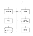
- FIG. 1 is a block diagram showing an embodiment of a hardware configuration of a diagnostic case presentation device for a structure according to an aspect of the present invention.
- the structure diagnosis case presentation device 1 can be configured by a personal computer, a workstation, or the like, and has a processor 10, a memory 11, a database 12, a display unit (display) 14, an input / output interface 16, and the like. And an operation unit 18 and the like are provided.
- the processor 10 is composed of a CPU (Central Processing Unit) and the like, and controls each part of the diagnosis case presentation device 1 of the structure in an integrated manner, and for example, the first information acquisition unit 20 and the similar damage extraction unit 22 shown in FIG. -1, and functions as a specific diagnosis case extraction unit 24-1.
- CPU Central Processing Unit
- the structure includes a building, for example, a civil engineering structure such as a bridge, a tunnel, and a dam, and also includes a building such as a building, a house, a building wall, a pillar, and a beam.
- a building for example, a civil engineering structure such as a bridge, a tunnel, and a dam
- a building such as a building, a house, a building wall, a pillar, and a beam.
- the processor 10 uses the similar damage extraction unit 22-1 and the specific diagnosis case extraction unit 24-1 to obtain information on the structure (past information). ) Etc. are extracted from the database 12 that stores the specific diagnosis cases, and the information related to the extracted specific diagnosis cases is output to the display unit 14.
- the details of the first information acquisition unit 20, the similar damage extraction unit 22-1, and the specific diagnosis case extraction unit 24-1 shown in FIG. 2 will be described later.
- the memory 11 includes a flash memory, a ROM (Read-only Memory), a RAM (Random Access Memory), and the like.
- the flash memory and ROM are non-volatile memories for storing various programs including an operation system and a diagnostic case presentation program for a structure according to an aspect of the present invention.
- the RAM functions as a work area for processing by the processor 10.
- a diagnostic case presentation program or the like of the structure stored in the flash memory or the like is temporarily stored.
- the processor 10 may include a part (RAM) of the memory 11.
- the structure diagnosis case presentation program may be recorded and distributed on an external recording medium (not shown), and may be installed by the processor 10 from the recording medium.
- the structure diagnosis case presentation program is stored in a server or the like connected to the network in a state accessible from the outside, downloaded to the flash memory or ROM by the processor 10 as requested, installed and executed. May be good.
- the processor 10 controls and processes each part of the structure diagnosis case presentation device 1 while using the RAM as a work area according to the structure diagnosis case presentation program.
- Database 12 is a part that stores and manages information about a structure and diagnosis results of two or more time points for damage to the structure in association with each other. Information on the structure managed by the database 12 and details of the diagnosis results at two or more time points for damage to the structure will be described later.
- the display unit 14 displays information related to the specific diagnosis case extracted by the processor 10 based on the information about the target structure to be diagnosed.
- the diagnostician can make a diagnosis by referring to the information related to the specific diagnosis case presented on the display.
- the display can be used as a part of the user interface when receiving the instruction of the diagnostician.
- the input / output interface 16 includes a connection that can be connected to an external device, a communication unit that can be connected to a network, and the like.
- a connection unit that can be connected to an external device USB (Universal Serial Bus), HDMI (High-Definition Multimedia Interface) (HDMI is a registered trademark) and the like can be applied.
- the processor 10 can acquire information and the like regarding a desired target structure via the input / output interface 16. Further, instead of the display unit 14, it is possible to use an external display device connected to the input / output interface 16.
- the operation unit 18 includes a keyboard, a pointing device such as a mouse, and a keyboard, and functions as a user interface that accepts various specifications by a diagnostician.
- FIG. 2 is a block diagram showing a first embodiment of a diagnostic case presentation device for a structure according to an aspect of the present invention.
- the structure diagnosis case presentation device of the first embodiment shown in FIG. 2 is composed of the processor 10, the database 12, and the display unit 14 of the structure diagnosis case presentation device 1 having the hardware configuration shown in FIG.
- the processor 10 functions as a first information acquisition unit 20, a similar damage extraction unit 22-1, and a specific diagnosis case extraction unit 24-1.
- the first information acquisition unit 20 that functions as an input unit performs information acquisition processing for acquiring information about the target structure including at least one of a photographed image and damage information of the target structure to be diagnosed according to an instruction from the diagnostician. ..
- the first information acquisition unit 20 shall acquire damage information of the target structure.
- the damage information of the target structure acquired by the first information acquisition unit 20 is output to the similar damage extraction unit 22-1.
- the database 12 is a part that stores and manages information on a large number of structures diagnosed in the past in association with diagnosis results at two or more time points for damage to the structures.
- the information about the structure includes at least one of the photographed image of the structure and the damage information of the structure.
- Damage information includes at least one of the type of damage to the structure, the location of the damage, and the extent of the damage. Further, an image (damage image) showing the damage detected from the photographed image of the structure may be included.
- the diagnosis result of two or more time points includes the diagnosis result of the first time point and the diagnosis result of the second time point which is later than the first time point.
- the diagnosis result at the first time point may be the diagnosis result at the initial stage of inspection or the diagnosis result at the time of periodic inspection for visual inspection.
- the diagnosis result at the time of the second inspection is a diagnosis result confirmed by a diagnostician different from the diagnostician at the first time (for example, including a council such as a result confirmation meeting for confirming the diagnosis), and a more detailed inspection than the visual inspection.
- the diagnosis result at the time point in addition to the visual inspection, the time point of inspection such as destructive inspection and non-destructive inspection), or the diagnosis result at the time of repair design of the structure can be considered.
- the diagnosis results at two or more time points may differ from the cases where they match, and the diagnosis results at the later time points are more probable than the previous diagnosis results.
- the diagnosis result is at least one of the following damage degree judgment results, countermeasure classification judgment results, soundness judgment results, damage cause estimation results, repair necessity judgment results, and repair method selection results. including. ⁇ Judgment result of degree of damage Judgment result of degree of damage a / b / c / d / e (Reference: Bridge periodic inspection procedure: Ministry of Land, Infrastructure, Transport and Tourism) ⁇ Judgment result of countermeasure category Countermeasure category: Judgment result of A / B / C / E, etc. (Reference: Bridge periodic inspection procedure: Ministry of Land, Infrastructure, Transport and Tourism) A: There is no need to repair. B: It is necessary to repair depending on the situation.
- C1 From the viewpoint of preventive maintenance, it is necessary to promptly repair.
- C2 From the viewpoint of the safety of the bridge structure, it is necessary to promptly repair it.
- E1 From the viewpoint of the safety of the bridge structure, emergency response is required.
- E2 In addition, emergency response is required.
- M It is necessary to deal with maintenance work. S1: Detailed investigation is required. S2: Follow-up is required.
- the similar damage extraction unit 22-1 relates to the target structure among the information regarding the structure stored in the database 12 (information regarding a large number of structures diagnosed in the past) based on the information regarding the target structure. Extract information similar to the information.
- the database 12 contains at least one of the captured images at a plurality of time points obtained by photographing the same portion of the structure, the damage information at the plurality of time points detected from the photographed images at the plurality of time points, and the information indicating the change over time of the damage information.
- the first information acquisition unit 20 needs to acquire information about the target structure at a plurality of time points.
- the similar damage extraction process by the similar damage extraction unit 22-1 detects the change over time of the damage information based on the information about the target structure at a plurality of time points, and the information indicating the change with time is obtained from the database 12 for the damage of the target structure. It can be used as one of the information when extracting similar damage similar to. This makes it possible to extract specific diagnostic cases with similar changes over time in damage information.
- the similar damage extraction unit 22-1 makes a similar determination in consideration of at least one of information other than the damage information, for example, structural information, environmental information, history information, and inspection information of the structure. You may do it. The details of the structural information, environmental information, history information, and inspection information of the structure will be described later.
- the specific diagnosis case extraction unit 24-1 is a specific diagnosis among the diagnosis results (that is, the diagnosis results associated with the information of the similar damage) of the structure having the similar damage extracted by the similar damage extraction unit 22-1.
- the result (specific diagnosis case) is extracted from the database 12.
- the diagnostic result extracted as a specific diagnostic case is a diagnostic result of a structure having different diagnostic results at two or more time points.
- the specific diagnosis case is a past diagnosis result having damage similar to the damage of the target structure, and the diagnosis result at two or more time points is different (misdiagnosis result or diagnosis result easily erroneous).
- the processor 10 outputs information related to the specific diagnosis case extracted by the specific diagnosis case extraction unit 24-1 to the display unit 14.
- the display unit 14 causes the specific diagnosis case presentation unit 14A to display information related to the specific diagnosis case.
- the information related to the specific diagnosis case includes the specific diagnosis case itself, the information that evokes the fact that the case is prone to misdiagnosis, separately from the specific diagnosis case, or in combination with the specific diagnosis case.
- the display unit 14 can display a photographed image, a damaged image, a damage diagram, and the like of the target structure.
- the diagnostician can make a diagnosis by referring to the information related to the specific diagnosis case presented to the specific diagnosis case presentation unit 14A, so that even a non-skilled diagnostician is appropriate. Diagnosis is possible.
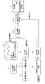
- FIG. 3 is a block diagram showing a second embodiment of a diagnostic case presentation device for a structure according to an aspect of the present invention.
- the structure diagnosis case presentation device of the second embodiment shown in FIG. 3 is composed of the processor 10, the database 12, and the display unit 14 of the structure diagnosis case presentation device 1 having the hardware configuration shown in FIG.
- the processor 10 serves as an image acquisition unit 32, a damage detection unit 34, an actual size information acquisition unit 35, a panorama synthesis unit 36, a second information acquisition unit 38, a similar damage extraction unit 22-2, and a specific diagnosis case extraction unit 24-2. Function.
- the image acquisition unit 32, the damage detection unit 34, the actual size information acquisition unit 35, and the panorama composition unit 36 are parts corresponding to the first information acquisition unit 20 shown in FIG. 2, and are included in the information 30 regarding the target structure. Damage information is generated based on the captured image of the target structure.
- the image acquisition unit 32 acquires a photographed image of the target structure to be diagnosed according to an instruction from the diagnostician, and outputs the acquired photographed image to the damage detection unit 34.
- the damage detection unit 34 performs damage detection processing for detecting damage to the target structure shown in the captured image based on the captured image of the target structure input from the image acquisition unit 32.
- the damage detection unit 34 can apply, for example, a trained model such as CNN (Convolution Neural Network) that has been machine-learned to detect damage, but the damage detection unit 34 is not limited to this and detects damage by a detection algorithm. It may be a thing.
- CNN Convolution Neural Network
- the actual size information is the actual size of the characteristic portion (for example, the length, width, etc. of the steel member) of the target structure in the captured image, or the resolution (mm / pixel) of the subject.
- the damage detection unit 34 detects the damage of the target structure and detects the size of the damage (if the damage is a crack, the crack length and the crack width) or the degree of the damage based on the actual size information. Can be done. This makes it possible to extract specific diagnostic cases with similar degrees (magnitudes) of damage.
- the damage detection unit 34 may include cracks, water leaks / free lime, peeling / reinforcing bar exposure, floating, surface air bubbles, bean board (junker), cold joints, lap lines, sand streaks, slag leaks, etc. as damage to the concrete member. Damage can be detected, and damage such as cracks, corrosion, and deterioration of anticorrosion function can be detected as damage to the steel member. Further, the damage detection result may be appropriately corrected by the diagnostician.
- damage information detected by the damage detection unit 34 the type of damage to the structure, the position of the damage, and the degree of damage (length, width, area, density, depth, mean value, maximum value, etc.). It may contain at least one of them.
- the panoramic compositing unit 36 panoramicly synthesizes the divided image group and also provides damage information (damaged image). Performs a compositing process for panoramic compositing.
- the target structure is divided and captured (overlap between adjacent images). Shooting including the part) and acquire the divided shot image group. Then, by panoramic synthesis of the divided shot image group and panoramic synthesis of the damage information, for example, when one crack is shot over a plurality of shot images, the cracks in each shot image can be connected. can. If a desired resolution can be obtained from a single captured image, the panoramic composition by the panoramic composition unit 36 can be omitted.
- the damage information of the target structure generated in this way is output to the similar damage extraction unit 22-2.
- the second information acquisition unit 38 acquires information (other information) other than the captured image among the information 30 regarding the target structure as the second information.
- Other information includes at least one of the following structural information, environmental information, history information, and inspection information of the structure.
- -Structural information Structural type (in the case of bridges: girder bridge, ramen bridge, truss bridge, arch bridge, diagonal bridge, suspension bridge), member type (in the case of bridge: floor slab, bridge pedestal, abutment, girder ...), Materials (steel, reinforced concrete, PC (Prestressed Concrete) ...), etc.
- -Environmental information Traffic volume (per day, per month, per year, cumulative, etc.), distance from the sea, climate (average temperature, average) Humidity, rainfall, snowfall, etc.)
- History information Construction conditions (temperature at construction, etc.), age (completion date, service start date, age since then), repair history, disaster history (earthquake, typhoon, flood, etc.)
- Inspection information Monitoring information (deflection of structure, vibration amplitude, vibration cycle, etc.), core
- the second information acquisition unit 38 acquires other information (second information) among the information 30 regarding the target structure, outputs the second information to the similar damage extraction unit 22-2, and indicates the diagnostic purpose.
- the information is output to the specific diagnosis case extraction unit 24-2.
- the information indicating the diagnostic purpose is not limited to the case where the second information acquisition unit 38 outputs the information indicating the diagnostic purpose to the specific diagnosis case extraction unit 24-2, and the diagnostician uses the operation unit 18 to perform specific diagnosis of the information indicating the diagnostic purpose. It may be input to the case extraction unit 24-2.
- the similar damage extraction unit 22-2 is based on the damage information of the target structure input from the panorama synthesis unit 36 and the information about the target structure including the second information (other information) input from the second information acquisition unit 38. Then, from the information on a large number of past structures stored in the database 12, information similar to the information on the target structure (information similar to the damage information and other information) is extracted.
- FIG. 4 is a diagram showing an example of a method for extracting similar damage by the similar damage extraction unit.
- the damage information related to the structure stored in the database 12 is indicated by a cross, and the damage information to be diagnosed this time is indicated by a ⁇ mark.
- the feature vector A indicates the maximum crack width (mm)
- the feature vector B indicates the number of years after the start of service of the structure.
- the feature space based on the feature vectors can be a multidimensional space composed of three or more feature vectors, but in FIG. 4, for the sake of simplicity, the two-dimensional space composed of two feature vectors is shown.
- the similar damage extraction unit 22-2 has a feature vector (first feature vector) of the damage information of the current diagnosis target indicated by ⁇ and a feature vector of damage information indicated by ⁇ (x).
- the distance to the second feature vector) is calculated, and the damage information indicated by the cross mark whose distance is equal to or less than the threshold value (inside the circle shown by the dotted line in FIG. 4) is extracted as similar damage.
- This threshold can be optimized by statistical methods.
- the distance may be a distance when the plurality of parameters of the first feature vector and the second feature vector are not weighted (Euclidean distance), or may be a distance when weighted (Mahalanobis distance). What kind of weight is assigned to which parameter may be determined by a statistical method such as principal component analysis.
- additional search conditions can be specified as points or ranges in the feature space. For example, when a bridge whose completion date is January 1, 1990 or later and a girder bridge whose basic structure is specified are specified, damage similar to that of the structure can be extracted within the specified range.
- damage information In addition to the above, damage information, structural information, environmental information, history information, inspection information, etc. included in other information can be set as the axis of the feature space, and similar damage can be extracted.
- the method for extracting similar damage may use a method different from the method for determining by the distance in the feature space.
- it may be extracted by AI (Artificial Intelligence) for determining the similarity from an image, or AI for determining the similarity by combining a plurality of information among images, damage information, and other information.
- AI Artificial Intelligence
- the specific diagnosis case extraction unit 24-2 is a structure having different diagnosis results at two or more time points among the diagnosis results of the structure having similar damage.
- the diagnosis result is extracted from the database 12 as a specific diagnosis case, and the specific diagnosis case is further extracted on condition that the diagnostic purpose and the diagnostic purpose of the target structure match.
- FIG. 5 is a chart showing the types of diagnostic purposes and the diagnostic results at two time points for each diagnostic purpose. Note that FIG. 5 shows the case where the diagnosis results at the two time points (first time point and second time point) are different.
- the specific diagnosis case extraction unit 24-2 extracts specific diagnosis cases in which the soundness judgment results differ at two time points. do.
- the purpose of diagnosis may be two or more. In this case, it is preferable to extract specific diagnosis cases in which the diagnosis results of two or more diagnostic purposes are different at two time points, but the specific diagnosis results in which one or more of the two or more diagnostic purposes are different at two time points. Cases may be extracted.
- the specific diagnosis case extraction unit 24-2 detects a plurality of specific diagnosis cases, the specific diagnosis case with the highest degree of similarity may be extracted, or the top plurality (for example, up to the third place) having the highest degree of similarity. ) May be extracted.
- the display unit 14 displays the information related to the specific diagnosis case extracted by the specific diagnosis case extraction unit 24-2 on the specific diagnosis case presentation unit 14A.
- the plurality of specific diagnosis cases are displayed side by side in descending order of similarity, or according to the scroll operation of the diagnostician.
- a plurality of specific diagnosis cases may be scrolled and displayed in descending order of similarity.
- the display unit 14 can display information 30 (photographed image of the target structure and other information) regarding the target structure, damage information, and the like.
- the diagnostician can make a diagnosis by referring to the information related to the specific diagnosis case presented to the specific diagnosis case presentation unit 14A, so that even a non-skilled diagnostician is appropriate. Diagnosis is possible.
- the processor 10 has the number of similar damages extracted by the similar damage extraction units 22-1 and 22-2 (similar damage extraction processing) and the specific diagnosis case extraction units 24-1 and 24-2 (specific diagnosis case extraction).
- the misdiagnosis rate calculation process for calculating the misdiagnosis rate of the specific diagnosis case based on the number of the specific diagnosis cases extracted by the process) can be performed.
- the processor 10 extracts at least one similar damage in the similar damage extraction units 22-1 and 22-2 (similar damage extraction process). Further, the processor 10 extracts at least one specific diagnosis case in the specific diagnosis case extraction units 24-1 and 24-2 (specific diagnosis case extraction process).
- the misdiagnosis rate can be calculated by the ratio of the total number of similar injuries to the number of specific diagnosis cases in which the diagnosis results at two time points are different among similar injuries.
- the processor 10 can display a specific diagnosis case and a misdiagnosis rate on the display unit 14.
- the processor 10 can display at least one specific diagnosis case and a misdiagnosis rate on the display unit 14. By presenting the misdiagnosis rate together with the specific diagnosis case, the diagnostician can determine whether the diagnosis for damage to the target structure is likely to be misdiagnosed, and if the misdiagnosis rate is high, specify it. It is possible to make a more careful diagnosis by referring to the diagnosis cases.
- FIG. 6 is a flowchart showing an embodiment of a method for presenting a diagnostic case of a structure according to an aspect of the present invention. The processing of each step shown in FIG. 6 is performed by the processor 10 of the diagnosis case presentation device 1 of the structure shown in FIG.
- the processor 10 acquires a photographed image of the target structure to be diagnosed according to an instruction from the diagnostician (step S10).
- the processor 10 detects damage to the target structure shown in the captured image based on the captured image of the target structure, and acquires damage information indicating the damage (step S20, damage detection process, information acquisition process).
- the processor 10 extracts similar damage similar to the damage of the target structure from the database 12 based on the information about the target structure including the damage information and the information about the structure stored in the database 12 (step S30, similar). Damage extraction process).
- the processor 10 extracts from the database 12 a specific diagnostic result (a specific diagnostic result in which the diagnostic results at two or more time points are different) among the diagnostic results of the structure having similar damage extracted in step S30 (step S40). , Specific diagnosis case extraction process).
- the specific diagnosis result is a diagnosis result that is misdiagnosed or is likely to be misdiagnosed because the diagnosis results at two or more time points are different.
- the processor 10 outputs the information related to the specific diagnosis case extracted in step S30 to the display unit 14 and displays it on the specific diagnosis case presentation unit 14A (step S50, output processing).
- information related to the specific diagnosis case it is preferable to include a photographed image, damage information, etc. corresponding to the specific diagnosis case, in addition to the diagnosis result in which the diagnosis results at two or more time points are different.
- the diagnostician when diagnosing the target structure, the diagnostician can make a diagnosis with reference to the information related to the specific diagnosis case presented to the specific diagnosis case presentation unit 14A, even if he / she is not a skilled diagnostician. Appropriate diagnosis is possible.
- specific diagnostic cases in which the diagnostic results at two or more time points are different are extracted from the diagnostic results of the structure having similar damage similar to the damage of the target structure, but the present invention is not limited to this. From the cases where the diagnosis results at two or more time points are different, the diagnosis result of the structure having similar damage similar to the damage of the target structure may be extracted as a specific diagnosis case.
- the hardware-like structure of the processing unit and the database 12 that execute various processes such as a CPU are various processors as shown below.
- the circuit configuration can be changed after manufacturing the CPU (Central Processing Unit), FPGA (Field Programmable Gate Array), etc., which are general-purpose processors that execute software (programs) and function as various processing units.
- Programmable Logic Device PLD
- Programmable Logic Device PLD
- ASIC Application Specific Integrated Circuit
- One processing unit may be composed of one of these various processors, or may be composed of two or more processors of the same type or different types (for example, a plurality of FPGAs or a combination of a CPU and an FPGA). You may. Further, a plurality of processing units may be configured by one processor. As an example of configuring a plurality of processing units with one processor, first, one processor is configured by a combination of one or more CPUs and software, as typified by a computer such as a client or a server. There is a form in which the processor functions as a plurality of processing units.
- SoC System On Chip
- the various processing units are configured by using one or more of the above-mentioned various processors as a hardware-like structure.
- circuitry in which circuit elements such as semiconductor elements are combined.
- the present invention records a structure diagnosis case presentation program that causes the computer to function as a diagnosis case presentation device for the structure according to the present invention by being installed in the computer, and a diagnosis case presentation program for this structure. Includes non-volatile storage media.
- Diagnosis case presentation device 10
- Memory 12
- Database 14
- Display unit 14A
- Specific diagnosis case presentation unit 16
- Input / output interface 18
- Operation unit 20
- Specific diagnosis case extraction unit 32
- Image acquisition unit 34
- Damage detection unit 35
- Actual size information acquisition unit 36
- Panorama synthesis unit 38
Landscapes
- Engineering & Computer Science (AREA)
- Theoretical Computer Science (AREA)
- General Physics & Mathematics (AREA)
- Physics & Mathematics (AREA)
- General Engineering & Computer Science (AREA)
- Data Mining & Analysis (AREA)
- Databases & Information Systems (AREA)
- Computer Vision & Pattern Recognition (AREA)
- Quality & Reliability (AREA)
- Library & Information Science (AREA)
- Software Systems (AREA)
- Investigating Materials By The Use Of Optical Means Adapted For Particular Applications (AREA)
- Testing Of Devices, Machine Parts, Or Other Structures Thereof (AREA)
- Medical Treatment And Welfare Office Work (AREA)
Priority Applications (4)
| Application Number | Priority Date | Filing Date | Title |
|---|---|---|---|
| JP2022553564A JP7795468B2 (ja) | 2020-10-02 | 2021-08-31 | 構造物の診断事例提示装置、方法及びプログラム |
| EP21875034.7A EP4224415A4 (en) | 2020-10-02 | 2021-08-31 | Structure diagnostic-case presentation device, method, and program |
| CN202180064616.3A CN116235206A (zh) | 2020-10-02 | 2021-08-31 | 结构物的诊断事例提示装置、方法及程序 |
| US18/193,390 US12586172B2 (en) | 2020-10-02 | 2023-03-30 | Structure diagnostic case presentation device, method, and program |
Applications Claiming Priority (2)
| Application Number | Priority Date | Filing Date | Title |
|---|---|---|---|
| JP2020167557 | 2020-10-02 | ||
| JP2020-167557 | 2020-10-02 |
Related Child Applications (1)
| Application Number | Title | Priority Date | Filing Date |
|---|---|---|---|
| US18/193,390 Continuation US12586172B2 (en) | 2020-10-02 | 2023-03-30 | Structure diagnostic case presentation device, method, and program |
Publications (1)
| Publication Number | Publication Date |
|---|---|
| WO2022070731A1 true WO2022070731A1 (ja) | 2022-04-07 |
Family
ID=80950046
Family Applications (1)
| Application Number | Title | Priority Date | Filing Date |
|---|---|---|---|
| PCT/JP2021/031912 Ceased WO2022070731A1 (ja) | 2020-10-02 | 2021-08-31 | 構造物の診断事例提示装置、方法及びプログラム |
Country Status (5)
| Country | Link |
|---|---|
| US (1) | US12586172B2 (https=) |
| EP (1) | EP4224415A4 (https=) |
| JP (1) | JP7795468B2 (https=) |
| CN (1) | CN116235206A (https=) |
| WO (1) | WO2022070731A1 (https=) |
Cited By (1)
| Publication number | Priority date | Publication date | Assignee | Title |
|---|---|---|---|---|
| WO2025258396A1 (ja) * | 2024-06-10 | 2025-12-18 | 富士フイルム株式会社 | 損傷情報処理装置、損傷情報処理装置の作動方法、及びプログラム |
Families Citing this family (1)
| Publication number | Priority date | Publication date | Assignee | Title |
|---|---|---|---|---|
| JP7510512B2 (ja) * | 2020-09-29 | 2024-07-03 | 富士フイルム株式会社 | 損傷情報処理装置、損傷情報処理方法、及びプログラム |
Citations (5)
| Publication number | Priority date | Publication date | Assignee | Title |
|---|---|---|---|---|
| JP2016126769A (ja) * | 2014-12-26 | 2016-07-11 | 古河機械金属株式会社 | 検査結果出力装置、検査結果出力方法、及び、プログラム |
| JP2016211955A (ja) * | 2015-05-08 | 2016-12-15 | 古河電気工業株式会社 | 橋梁点検支援装置、橋梁点検支援方法、橋梁点検支援システム、およびプログラム |
| WO2018207173A1 (en) * | 2017-05-07 | 2018-11-15 | Manam Applications Ltd. | System and method for construction 3d modeling and analysis |
| JP2018198053A (ja) | 2017-05-22 | 2018-12-13 | キヤノン株式会社 | 情報処理装置、情報処理方法、及びプログラム |
| WO2019163329A1 (ja) * | 2018-02-21 | 2019-08-29 | 富士フイルム株式会社 | 画像処理装置及び画像処理方法 |
Family Cites Families (8)
| Publication number | Priority date | Publication date | Assignee | Title |
|---|---|---|---|---|
| US8494810B2 (en) * | 2009-06-05 | 2013-07-23 | Jentek Sensors, Inc. | Component adaptive life management |
| JP2011145859A (ja) * | 2010-01-14 | 2011-07-28 | Nippon Telegr & Teleph Corp <Ntt> | ウェブコンテンツ診断支援装置、ウェブコンテンツ診断支援方法及びプログラム |
| CN108431585B (zh) | 2015-12-25 | 2021-09-14 | 富士胶片株式会社 | 信息处理装置及信息处理方法 |
| CN106056223B (zh) * | 2016-05-27 | 2020-04-14 | 大连楼兰科技股份有限公司 | 用于车辆远程诊断与备件检索的平台 |
| CN109655680A (zh) * | 2017-11-15 | 2019-04-19 | 杨凯 | 一种高速公路机电设备故障诊断、解决方法及系统 |
| CN111104306A (zh) | 2018-10-26 | 2020-05-05 | 伊姆西Ip控股有限责任公司 | 用于应用中的错误诊断的方法、装置和计算机存储介质 |
| CN113167037B (zh) | 2018-11-29 | 2023-04-25 | 富士胶片株式会社 | 构造物的修复施工方法选定系统、修复施工方法选定方法及修复施工方法选定服务器 |
| CN111682960A (zh) * | 2020-05-14 | 2020-09-18 | 深圳市有方科技股份有限公司 | 一种物联网网络及设备的故障诊断方法及装置 |
-
2021
- 2021-08-31 EP EP21875034.7A patent/EP4224415A4/en active Pending
- 2021-08-31 CN CN202180064616.3A patent/CN116235206A/zh active Pending
- 2021-08-31 JP JP2022553564A patent/JP7795468B2/ja active Active
- 2021-08-31 WO PCT/JP2021/031912 patent/WO2022070731A1/ja not_active Ceased
-
2023
- 2023-03-30 US US18/193,390 patent/US12586172B2/en active Active
Patent Citations (5)
| Publication number | Priority date | Publication date | Assignee | Title |
|---|---|---|---|---|
| JP2016126769A (ja) * | 2014-12-26 | 2016-07-11 | 古河機械金属株式会社 | 検査結果出力装置、検査結果出力方法、及び、プログラム |
| JP2016211955A (ja) * | 2015-05-08 | 2016-12-15 | 古河電気工業株式会社 | 橋梁点検支援装置、橋梁点検支援方法、橋梁点検支援システム、およびプログラム |
| WO2018207173A1 (en) * | 2017-05-07 | 2018-11-15 | Manam Applications Ltd. | System and method for construction 3d modeling and analysis |
| JP2018198053A (ja) | 2017-05-22 | 2018-12-13 | キヤノン株式会社 | 情報処理装置、情報処理方法、及びプログラム |
| WO2019163329A1 (ja) * | 2018-02-21 | 2019-08-29 | 富士フイルム株式会社 | 画像処理装置及び画像処理方法 |
Non-Patent Citations (1)
| Title |
|---|
| See also references of EP4224415A4 |
Cited By (1)
| Publication number | Priority date | Publication date | Assignee | Title |
|---|---|---|---|---|
| WO2025258396A1 (ja) * | 2024-06-10 | 2025-12-18 | 富士フイルム株式会社 | 損傷情報処理装置、損傷情報処理装置の作動方法、及びプログラム |
Also Published As
| Publication number | Publication date |
|---|---|
| JPWO2022070731A1 (https=) | 2022-04-07 |
| CN116235206A (zh) | 2023-06-06 |
| EP4224415A1 (en) | 2023-08-09 |
| US20230245296A1 (en) | 2023-08-03 |
| JP7795468B2 (ja) | 2026-01-07 |
| US12586172B2 (en) | 2026-03-24 |
| EP4224415A4 (en) | 2024-04-10 |
Similar Documents
| Publication | Publication Date | Title |
|---|---|---|
| US11935143B2 (en) | Structure repair method selection system, structure repair method selection method, and structure repair method selection server | |
| JP7319432B2 (ja) | 学習用データ収集装置、学習用データ収集方法、及びプログラム | |
| JP7351849B2 (ja) | 構造物の損傷原因推定システム、損傷原因推定方法、及び損傷原因推定サーバ | |
| JP7595730B2 (ja) | 補修図生成装置、補修図生成方法及びプログラム | |
| CN108140218B (zh) | 健全度判定装置、健全度判定方法及健全度判定程序 | |
| WO2019163329A1 (ja) | 画像処理装置及び画像処理方法 | |
| JP7219192B2 (ja) | 構造物の劣化状態診断方法 | |
| US12586172B2 (en) | Structure diagnostic case presentation device, method, and program | |
| JP7564878B2 (ja) | 構造物の補修支援装置、方法、プログラム及び記録媒体 | |
| US20230260098A1 (en) | Structure inspection assistance apparatus, structure inspection assistance method, and program | |
| US20240257315A1 (en) | Information processing apparatus, method, and program, and image data structure | |
| JP2021140435A (ja) | 損傷特定装置、損傷特定方法および損傷特定プログラム | |
| CN117121043A (zh) | 结构物的状态预测装置、方法及程序 | |
| US11971331B2 (en) | Three-dimensional display device, three-dimensional display method, and program | |
| CN120677379A (zh) | 剥落预测装置、方法及程序 | |
| CN115176281B (zh) | 三维显示装置、方法及计算机可读取记录介质 | |
| CN120655947B (zh) | 基于人工智能的隐蔽工程质量检验方法及装置 | |
| Gu et al. | Research on concrete structure defect repair based on three-dimensional printing | |
| JP7323694B2 (ja) | 構造物の劣化状態診断方法 | |
| Balakumar et al. | Automating Defect Detection for the Preservation of Historical Structures | |
| WO2023203964A1 (ja) | 情報処理装置、情報処理方法及びプログラム |
Legal Events
| Date | Code | Title | Description |
|---|---|---|---|
| 121 | Ep: the epo has been informed by wipo that ep was designated in this application |
Ref document number: 21875034 Country of ref document: EP Kind code of ref document: A1 |
|
| ENP | Entry into the national phase |
Ref document number: 2022553564 Country of ref document: JP Kind code of ref document: A |
|
| NENP | Non-entry into the national phase |
Ref country code: DE |
|
| ENP | Entry into the national phase |
Ref document number: 2021875034 Country of ref document: EP Effective date: 20230502 |