WO2022070586A1 - 塗布装置及びインクジェット印刷装置 - Google Patents
塗布装置及びインクジェット印刷装置 Download PDFInfo
- Publication number
- WO2022070586A1 WO2022070586A1 PCT/JP2021/028389 JP2021028389W WO2022070586A1 WO 2022070586 A1 WO2022070586 A1 WO 2022070586A1 JP 2021028389 W JP2021028389 W JP 2021028389W WO 2022070586 A1 WO2022070586 A1 WO 2022070586A1
- Authority
- WO
- WIPO (PCT)
- Prior art keywords
- bar
- coating
- base material
- coating liquid
- bar coater
- Prior art date
- Legal status (The legal status is an assumption and is not a legal conclusion. Google has not performed a legal analysis and makes no representation as to the accuracy of the status listed.)
- Ceased
Links
Images







Classifications
-
- B—PERFORMING OPERATIONS; TRANSPORTING
- B05—SPRAYING OR ATOMISING IN GENERAL; APPLYING FLUENT MATERIALS TO SURFACES, IN GENERAL
- B05C—APPARATUS FOR APPLYING FLUENT MATERIALS TO SURFACES, IN GENERAL
- B05C1/00—Apparatus in which liquid or other fluent material is applied to the surface of the work by contact with a member carrying the liquid or other fluent material, e.g. a porous member loaded with a liquid to be applied as a coating
- B05C1/04—Apparatus in which liquid or other fluent material is applied to the surface of the work by contact with a member carrying the liquid or other fluent material, e.g. a porous member loaded with a liquid to be applied as a coating for applying liquid or other fluent material to work of indefinite length
- B05C1/08—Apparatus in which liquid or other fluent material is applied to the surface of the work by contact with a member carrying the liquid or other fluent material, e.g. a porous member loaded with a liquid to be applied as a coating for applying liquid or other fluent material to work of indefinite length using a roller or other rotating member which contacts the work along a generating line
-
- B—PERFORMING OPERATIONS; TRANSPORTING
- B05—SPRAYING OR ATOMISING IN GENERAL; APPLYING FLUENT MATERIALS TO SURFACES, IN GENERAL
- B05C—APPARATUS FOR APPLYING FLUENT MATERIALS TO SURFACES, IN GENERAL
- B05C11/00—Component parts, details or accessories not specifically provided for in groups B05C1/00 - B05C9/00
-
- B—PERFORMING OPERATIONS; TRANSPORTING
- B05—SPRAYING OR ATOMISING IN GENERAL; APPLYING FLUENT MATERIALS TO SURFACES, IN GENERAL
- B05C—APPARATUS FOR APPLYING FLUENT MATERIALS TO SURFACES, IN GENERAL
- B05C11/00—Component parts, details or accessories not specifically provided for in groups B05C1/00 - B05C9/00
- B05C11/10—Storage, supply or control of liquid or other fluent material; Recovery of excess liquid or other fluent material
-
- B—PERFORMING OPERATIONS; TRANSPORTING
- B05—SPRAYING OR ATOMISING IN GENERAL; APPLYING FLUENT MATERIALS TO SURFACES, IN GENERAL
- B05C—APPARATUS FOR APPLYING FLUENT MATERIALS TO SURFACES, IN GENERAL
- B05C5/00—Apparatus in which liquid or other fluent material is projected, poured or allowed to flow on to the surface of the work
-
- B—PERFORMING OPERATIONS; TRANSPORTING
- B41—PRINTING; LINING MACHINES; TYPEWRITERS; STAMPS
- B41J—TYPEWRITERS; SELECTIVE PRINTING MECHANISMS, i.e. MECHANISMS PRINTING OTHERWISE THAN FROM A FORME; CORRECTION OF TYPOGRAPHICAL ERRORS
- B41J2/00—Typewriters or selective printing mechanisms characterised by the printing or marking process for which they are designed
- B41J2/005—Typewriters or selective printing mechanisms characterised by the printing or marking process for which they are designed characterised by bringing liquid or particles selectively into contact with a printing material
- B41J2/01—Ink jet
Definitions
- the present invention relates to a coating device and an inkjet printing device.
- high-speed fixing means fixing for a short period of time.
- the printing speed means the period required for one printed matter
- the high printing speed means that the period required for one printed matter is relatively short.
- velocity as used herein may include the meaning of velocity, which represents a scalar quantity of velocity.
- Examples of base material conditions include the type of base material including the material of the base material and the size of the base material.
- the size of the base material represents the length in the width direction of the base material and the thickness of the base material.
- the width of the base material represents a direction orthogonal to the direction in which the base material is conveyed.
- the coating device is required to maintain a uniform coating amount under various printing conditions.
- the coating apparatus preferably has a configuration in which parameters for controlling the coating amount can be easily changed.
- the volume of the cell and the groove for measuring the coating liquid can be easily changed.
- a gravure type coating device that measures the coating liquid using a gravure roll, such as a gravure coater and a kiss reverse coater, it is not easy to replace the heavy gravure roll, and it takes time to replace the gravure roll.
- the gravure type coating device has a limited number of parameters for controlling the coating amount as compared with other methods. Further, in the gravure type coating device, when the width of the base material is changed, it is necessary to replace the gravure roll or the like that does not correspond to the width of the base material with the gravure roll or the like that corresponds to the width of the base material. be. Then, the gravure type coating device requires more time and effort to replace the gravure roll and the like as compared with other methods, and there is a problem in properly switching the width of the base material.
- the bar coater In the bar coating type coating device equipped with a bar coater, the bar coater is extremely lightweight compared to the gravure roll, and the bar coater can be easily replaced. In addition, there are abundant parameters for controlling the coating amount such as the type of bar coater, which is advantageous in terms of control variable meter as compared with other coating methods. Further, the bar coating type coating device is bladeless, which does not require scraping the coating liquid applied to the bar coater, and there is no concern about fluctuation in the coating amount due to wear of the bar coater.
- the bar coating type coating device can easily switch printing conditions such as printing speed and substrate conditions in one day's printing work, and can meet various printing conditions according to the user's request. Printing work can be carried out with minimal loss of work time.
- Patent Document 1 describes a coating device to which the bar coating method is applied.
- the device described in the same document is provided with a coating bar in which a plurality of spiral grooves are formed on the surface of a cylindrical bar, the web as a member to be coated is continuously run, the coating bar is brought into contact with the web, and the coating liquid is applied. Applied to the web.
- Patent Document 2 describes a coating device provided with a wire bar in which a wire is wound around a core metal. The device described in the same document brings the rotated wire bar into contact with the traveling web, and the coating liquid is applied from the wire bar to the web.
- the coating liquid is interposed between the bar coater and the bar receiving seat, but the bar receiving seat absorbs the coating liquid, and the bar receiving seat may expand. Then, frictional resistance may occur between the bar coater and the bar receiving seat.
- the core shake of the bar coater when rotating the bar member may occur.
- the core deviation of the bar coater when rotating the bar coater can cause frictional resistance between the bar coater and the bar receiving seat.
- the present invention has been made in view of such circumstances, and an object of the present invention is to provide a coating device and an inkjet printing device capable of suppressing wear of a bar member in a bar coating type coating device.
- the coating apparatus is a bar member having a cylindrical shape and rotatably supported about a central axis, and is a bar that rotates about the central axis and applies a coating liquid to the substrate by coming into contact with the substrate.
- a bar receiving member that is a bar receiving member that rotatably supports the bar member and stores a coating liquid supplied to the bar member, and the bar facing portion facing the bar member of the bar receiving member is provided.
- the material applied to the bar facing portion may be applied to the whole.
- a material having a surface free energy of 33 millinewtons per meter or less is applied to the bar facing portion.
- the shear stress on the bar member and the bar receiving member is reduced, and the wear of the bar member and the bar receiving member is suppressed.
- the bar member has a mass of 0.5 kg or more and 3.0 kg or less per meter.
- the bar member has a spiral convex portion formed on the side surface.
- the coating liquid moves along the non-convex portion between the adjacent convex portions, and the clogging of the substance contained in the coating liquid in the non-convex portion is suppressed.
- the bar member in such an embodiment there is a wire bar having a structure in which wires are spirally wound around the side surface of the base material.
- the bar member is the length of the convex portion.
- a and the length B of the non-convex portion satisfy B / A ⁇ 1.
- unevenness in the thickness of the coating liquid when the coating liquid is transferred from the bar member to the base material can be suppressed, and the thickness of the coating liquid applied to the base material can be made uniform.
- the non-convex portion is preferably a flat surface having a certain area.
- a spiral recess is formed on the side surface of the bar member.
- the coating liquid moves along the recesses, and clogging of the substances contained in the coating liquid in the recesses is suppressed.
- An example of the bar member in this embodiment is a wireless bar in which a spiral groove is formed on the side surface of the base material.
- the length of the non-recessed portion is A and the length of the recessed portion is B in the direction parallel to the central axis
- the length of the non-recessed portion A is A and the length of the recessed portion is B in the direction parallel to the central axis
- the length B of the recess satisfy B / A ⁇ 1.
- unevenness in the thickness of the coating liquid when the coating liquid is transferred from the bar member to the base material can be suppressed, and the thickness of the coating liquid applied to the base material can be made uniform.
- the bottom surface of the recess is preferably a flat surface having a certain area.
- the coating device includes a transport device for transporting by supporting the base material, and the transport device includes a moving mechanism for moving the position of the base material in a direction having a component in the vertical direction.
- the backup roller to be replaced when the size of the base material is changed becomes unnecessary, and it becomes easy to switch the coating device according to the size of the base material.
- the coating device includes a liquid storage unit for storing the coating liquid applied to the bar member and a collecting unit for collecting the coating liquid overflowing from the liquid storage unit.
- the coating liquid is circulated and a fresh coating liquid is supplied.
- a fresh coating liquid is supplied.
- Latex having a relatively low glass transition point can be contained in the coating liquid, and both the adhesion of the coating liquid to the substrate and the coating stability of the coating liquid to the substrate can be achieved at the same time.
- the liquid storage unit is provided at at least one of the upstream position and the downstream side position of the bar member in the substrate transport direction, and the recovery unit is a position where the liquid storage unit is provided. It is provided corresponding to.
- the excess coating liquid moves from the liquid storage part to the collection part. This can promote the circulation of the coating liquid.
- one or more processors and one or more memories are provided, and the processor acquires the coating conditions when applying the coating liquid to the substrate, and the memory according to the coating conditions is obtained.
- the stored parameters are read out, and the application of the coating liquid to the substrate is controlled based on the read out parameters.
- parameters can be set according to the coating conditions.
- the coating liquid contains 0.1% by mass or more of the surfactant.
- the lubricity of the coating liquid with respect to the bar member and the bar receiving member can be improved.
- the coating liquid contains latex.
- the surfactant is easily adsorbed around the latex dispersed in the coating liquid, and the lubricity of the coating liquid to the bar member and the bar receiving member can be improved.
- the coating liquid contains latex having an average particle diameter of 30 nanometers or more and 500 nanometers or less.
- the cleaning suitability of the bar member can be improved.
- the inkjet printing apparatus includes a coating device that applies a coating liquid that agglomerates ink to a printing medium, and an inkjet head that ejects ink to a printing medium to which the coating liquid is applied. It is a bar member that has a shape and is rotatably supported with respect to the central axis. A bar receiving member that supports and stores a coating liquid supplied to the bar member, and a bar facing portion facing the bar member of the bar receiving member has a water absorption rate of 0.05% or less. Inkjet printing equipment to which a material having a shore hardness of D60 or more is applied.
- the inkjet printing apparatus According to the inkjet printing apparatus according to the present disclosure, it is possible to obtain the same action and effect as the coating apparatus according to the present disclosure.
- the constituent requirements of the coating apparatus according to the other embodiment may be applied to the constituent requirements of the inkjet printing apparatus according to the other embodiment.
- FIG. 1 is an overall configuration diagram of a coating device according to an embodiment.
- FIG. 2 is a functional block diagram showing an electrical configuration of the coating device shown in FIG.
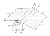
- FIG. 3 is a perspective view of the bar block shown in FIG.
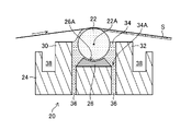
- FIG. 4 is a schematic diagram showing the internal structure of the bar block shown in FIG.
- FIG. 5 is a perspective view of the wire bar coater.
- FIG. 6 is a perspective view of the wireless bar coater.
- FIG. 7 is an enlarged view of the side surface of the wireless bar coater.
- FIG. 8 is a table showing the evaluation results of the wear evaluation of the bar coater with respect to the water absorption rate of the bar receiving portion and the hardness of the bar receiving portion.
- FIG. 8 is a table showing the evaluation results of the wear evaluation of the bar coater with respect to the water absorption rate of the bar receiving portion and the hardness of the bar receiving portion.
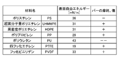
- FIG. 9 is a table showing the evaluation results of the wear evaluation of the bar coater with respect to the surface free energy of the bar receiving portion.
- FIG. 10 is a table showing the evaluation results of the wear evaluation of the bar coater with respect to the addition amount of the surfactant.
- FIG. 11 is a table for explaining the difference in effect between the bar coating method and other coating methods.
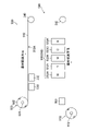
- FIG. 12 is an overall configuration diagram of an inkjet printing apparatus to which the coating apparatus according to the embodiment is applied.
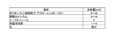
- FIG. 13 is a table showing a composition example of the precoat liquid according to another specific example.
- FIG. 14 is a table showing other composition examples of the precoat liquid according to other specific examples.
- FIG. 1 is an overall configuration diagram of a coating device according to an embodiment.
- the coating device 10 shown in the figure includes a bar coating device 12 for discharging the coating liquid and a transport device 14 for transporting the base material S.
- the coating device 10 supplies the coating liquid from the coating liquid supply device 50 to the bar coater 22 provided in the bar block 20 of the bar coating device 12, brings the base material S into contact with the bar coater 22, and applies the coating liquid to the base material S. Apply.
- the contact between the base material S and the bar coater 22 includes a state in which the coating liquid is discharged from the bar coater 22 and the coating liquid is present between the base material S and the bar coater 22.
- the bar coating device 12 includes a bar block 20, a base 40, and a coating liquid supply device 50.
- the bar block 20 includes a bar coater 22 and a bar support portion 24. The details of the bar block 20 will be described later.
- the bar coater 22 described in the embodiment is an example of a bar member.
- the bar coater 22 is rotatable and detachably supported by using the bar support mechanism provided in the bar support portion 24.
- the bar coater 22 is connected to the bar drive device.
- the bar drive device includes a motor that is a drive source of the bar coater 22, and a mechanical mechanism that connects the rotating shaft of the motor to the bar coater 22. In FIG. 1, the bar drive device is not shown.
- the bar drive device is illustrated with reference numeral 114 in FIG.
- the bar support mechanism that supports the bar coater 22 has, for example, a support structure for the bar coater 22 that corresponds to a plurality of bar coaters 22 having different effective coating lengths in the longitudinal direction corresponding to the width of the base material S.
- the coating device 10 may apply a bar coater 22 corresponding to coating conditions such as the width of the base material S.
- the illustration of the bar support mechanism is omitted.
- the bar block 20 is supported by using the base 40.
- the base 40 includes a mechanism for adjusting the horizontality representing an angle with respect to a horizontal plane in the width direction of the base material S.
- the width direction of the base material S is a direction orthogonal to the transport direction of the base material S and a direction parallel to the coating surface of the coating liquid of the base material S.
- the width direction of the base material S may be described as the base material width direction, and the transport direction of the base material S may be described as the base material transport direction.
- the width direction of the base material is the direction through which the paper surface of FIG. 1 is penetrated.
- the reference numeral y is used to represent the substrate transport direction.
- the reference numeral z is used to indicate the vertical direction.
- the angle of the base 40 with respect to the horizontal plane is adjusted, and the bar coater 22 is brought into contact with the base material S in parallel. Thereby, it is possible to suppress the variation in the lap width and the variation in the pressure generated between the coating liquid and the substrate S due to the uneven contact of the substrate S with respect to the bar coater 22.
- the lap width is the length of the region where the base material S and the bar coater 22 are in contact with each other in the base material width direction.
- the bar block 20 is regularly maintained for cleaning and parts replacement.
- the bar block 20 is removed from the base 40. Further, the bar block 20 that has undergone maintenance is attached to the base 40.
- the base 40 is configured so that the bar block 20 can be attached and detached. Further, the base 40 adopts a structure having high reproducibility of the arrangement position of the bar block 20. This makes it possible to improve the maintenance efficiency of the bar block 20 and maintain the coating performance before and after the maintenance.
- the coating liquid supply device 50 includes a supply flow path 52, a liquid feeding pump 54, and a coating liquid tank 56.
- the coating liquid stored in the coating liquid tank 56 is supplied to the bar block 20 via the liquid feeding pump 54 and the supply flow path 52.
- the coating liquid supply device 50 can control the amount of liquid to be sent to the bar block 20 to precisely control the amount of the coating liquid to be applied to the bar coater 22.
- the liquid feed pump 54 preferably has a method in which pulsation during liquid feed is suppressed.
- the coating liquid supply device 50 includes a circulation flow path 57, a circulation pump 58, and a recovery tank 59.
- the coating liquid discharged from the bar block 20 is collected in the collection tank 59 via the circulation flow path 57 and the circulation pump 58.
- the circulation pump 58 preferably has a method in which pulsation during liquid feeding is suppressed.
- the coating liquid collected in the recovery tank 59 may be returned to the coating liquid tank 56 and supplied to the bar block 20.
- the flow path connecting the recovery tank 59 and the coating liquid tank 56 may be provided with a filter, a densitometer, or the like.
- the transport device 14 transports the base material S along the base material transport direction.
- the transport device 14 includes a transport mechanism 60 and an elevating device 68.
- FIG. 1 illustrates, as an example of the base material S, a continuum to which roll-to-roll transfer is applied. In FIG. 1, the roll on the feeding side of the base material S and the roll on the winding side of the base material S are not shown.
- the transport mechanism 60 includes a first lift roller 62, a second lift roller 64, and a drive roller 66.
- a motor is connected to the drive roller 66.
- the drive roller 66 rotates according to the operation of the motor, supports the base material S, and conveys the base material S.
- the transport mechanism 60 includes one or more support rollers.
- the support roller is arranged at an arbitrary position in the base material transport path in the transport mechanism 60, and supports the base material S in the base material transport path. The illustration of the support roller is omitted.
- the first lift roller 62 and the second lift roller 64 support the base material S in the region where the coating liquid is applied from the bar block 20 to the base material S, and the large lap angle of the base material S with respect to the bar coater 22. The distance between the base material S and the bar coater 22 is adjusted.
- the first lift roller 62 and the second lift roller 64 are configured to be individually movable.
- the arrow line attached to the first lift roller 62 is the moving direction of the first lift roller 62, and represents the direction of the pressing force applied to the base material S by using the first lift roller 62.
- the first lift roller 62 can move in the substrate transport direction and the vertical direction.
- the arrow line attached to the second lift roller 64 is the moving direction of the second lift roller 64, and represents the direction of the pressing force applied to the base material S by using the second lift roller 64.
- the second lift roller 64 can move in the substrate transport direction and the vertical direction in the same manner as the first lift roller 62.
- the size of the lap angle of the base material S with respect to the bar coater 22 can be adjusted individually on the primary side and the secondary side of the bar coater 22. The same applies to the distance between the base material S and the bar coater 22.
- the primary side is the upstream side of the bar coater 22 in the substrate transport direction, and is the left side of the bar coater 22 in FIG. 1.
- the secondary side is the downstream side of the bar coater 22 in the substrate transport direction, and is the right side of the bar coater 22 in the figure.
- the lap angle of the base material S with respect to the bar coater 22 is preferably in the range of 2.0 degrees or more and 30 degrees or less. When the lap angle of the base material S with respect to the bar coater 22 is less than 2.0 degrees, the contact surface between the bar coater 22 and the base material S is not stable, and uneven coating of the coating liquid on the base material S may occur.
- a more preferable range of the lap angle of the base material S with respect to the bar coater 22 is 5.0 degrees or more and 20 degrees or less.
- the tension applied to the base material S when the base material S is conveyed is preferably 10 newtons or more and 200 newtons or less per meter.
- the tension applied to one meter of the base material S is less than 10 Newtons, wrinkles may occur on the base material S, and uneven coating of the coating liquid may occur.
- step unevenness of the coating liquid due to the frictional force between the tip portion of the bar block 20 and the base material S may occur.
- the tension applied to the base material S is distributed in the base material width direction at the position where the base material S and the bar coater 22 come into contact with each other, and the tension is applied to the base material S in the base material width direction. Uneven coating of the coating liquid may occur.
- a heat roller is provided at a position on the upstream side of the bar coater 22 in the base material transport direction to make the state of the base material S uniform in the base material width direction and suppress coating unevenness of the coating liquid in the base material width direction.
- the heat roller has a cylindrical shape and has a length corresponding to the length of the base material S in the width direction of the base material.
- the heat roller has a built-in heat source such as a heater, and supplies the heat released from the heat source to the base material S.
- the heat roller applies a certain tension to the base material S and contacts the base material S to smooth the base material S.
- the elevating device 68 moves the transport mechanism 60 in the vertical direction to adjust the distance between the base material S and the bar block 20 in the vertical direction.
- the elevating device 68 lowers the transport mechanism 60 to bring the base material S into contact with the bar coater 22.
- the elevating device 68 raises the transport mechanism 60 to separate the base material S from the bar coater 22.
- FIG. 2 is a functional block diagram showing an electrical configuration of the coating device shown in FIG.
- the coating device 10 includes one or more processors 100 and one or more memories 102.
- the processor 100 includes a transfer control unit 110, an elevating control unit 112, a bar drive control unit 113, a pump control unit 115, a coating condition acquisition unit 117, and a parameter setting unit 118. Each part provided in the processor 100 corresponds to the function of the coating device 10 realized by using the processor 100.
- the transport control unit 110 transmits a command signal to the transport mechanism 60, controls the operation of the transport mechanism 60, and controls the transport of the base material S.
- the transfer control unit 110 controls the operation of the motor connected to the drive roller 66 provided in the transfer mechanism 60.
- the transport control unit 110 controls the operation of the motor connected to the lift roller moving mechanism that moves the first lift roller 62 and the second lift roller 64. Further, the transport control unit 110 controls the feeding of the base material S and the winding of the base material S.
- the elevating control unit 112 transmits a command signal to the elevating device 68 and controls the operation of the elevating device 68.
- the elevating control unit 112 lowers the transport mechanism 60 from the retracted position and moves the transport mechanism 60 to the coating position at the start timing of the coating period of the coating liquid.
- the elevating control unit 112 raises the transport mechanism 60 from the coating position and moves the transport mechanism 60 to the retracted position at the end timing of the coating period of the coating liquid.
- the bar drive control unit 113 transmits a command signal to the bar drive device 114 and controls the operation of the bar drive device 114.
- the bar drive control unit 113 can set the rotation speed of the bar coater 22 according to the transport speed of the base material S.
- the bar drive control unit 113 sets the speed of the side surface of the bar coater 22 in the base material transport direction at a position in contact with the base material S of the bar coater 22 at 5.0% or more and 150% or less with respect to the transport speed of the base material S. Can be adjusted to range.
- the speed ratio is less than 5.0%, the friction between the bar coater 22 and the base material S becomes relatively large, and the coating liquid applied to the base material S may have stepped unevenness. If the speed ratio exceeds 150%, vibration occurs when the bar coater 22 rotates, which may cause uneven coating of the coating liquid applied to the base material S.
- the speed ratio is more preferably in the range of 10% or more and 100% or less.
- the bar drive control unit 113 controls the rotation direction of the bar coater 22. For example, when improving the surface condition of the coating liquid applied to the base material S, the bar drive control unit 113 reverses the bar coater 22.
- the pump control unit 115 sends a command signal to the pump 116 and controls the operation of the pump 116.
- the pump 116 shown in FIG. 2 represents the coating liquid tank 56 and the circulation pump 58 shown in FIG.
- the pump control unit 115 controls the amount of the coating liquid sent from the liquid feeding pump 54 to the bar block 20.
- the pump control unit 115 controls the amount of the coating liquid sent from the bar block 20 to the circulation pump 58.
- the coating condition acquisition unit 117 acquires the coating conditions applied to the coating device 10 via the input device 130, the input / output interface 140, and the like.
- the coating conditions may include the type of the base material S and the type of the coating liquid.
- the type of the base material S may include the material of the base material S and the size of the base material S.
- the size of the base material S may include the width of the base material S and the thickness of the base material S.
- the parameter setting unit 118 sets various parameters applied to the coating device 10 according to the coating conditions acquired by using the coating condition acquisition unit 117.
- Various control units such as the transport control unit 110 control the operation of each unit based on the parameters set by using the parameter setting unit 118.
- the processor 100 may display various parameters set by using the parameter setting unit 118 on the display device 120.
- the memory 102 includes a parameter storage unit 104.
- the parameter storage unit 104 stores various parameters applied to the coating device 10. Examples of various parameters include the rotation speed of the bar coater 22, the discharge amount per unit time of the liquid feed pump 54, the tension applied to the base material S from the first lift roller 62 and the like, and the like.
- the parameter setting unit 118 reads various parameters according to the coating conditions from the parameter storage unit 104 and sets them.
- the memory 102 stores various programs executed by using the processor 100. Various types of data may be stored in the memory 102. The memory 102 may be applied to an area of computation performed using the processor 100.
- the coating device 10 includes a display device 120 and an input device 130.
- the display device 120 displays various information applied to the coating device 10 based on the display signal transmitted from the display driver 122.
- a keyboard, mouse, or the like is applied to the input device 130.
- the input device 130 transmits an input signal according to the user's operation to the processor 100.
- the processor 100 performs various processes according to the input signal.
- the display device 120 and the input device 130 may be integrally configured by using the touch panel type display device 120.
- the coating device 10 includes an input / output interface 140.
- Various communication standards such as USB (Universal Serial Bus) can be applied to the input / output interface 140.
- An input / output interface 140 may be provided for each of the plurality of communication standards.
- processors can be applied to the hardware of the processing unit that performs various processes.
- the processing unit may be called a processing unit.
- Various processors include a CPU (Central Processing Unit), a PLD (Programmable Logic Device), an ASIC (Application Specific Integrated Circuit), and the like.
- the CPU is a general-purpose processor that executes programs and functions as various processing units.
- the PLD is a processor whose circuit configuration can be changed after manufacturing.
- An example of PLD is FPGA (Field Programmable Gate Array).
- An ASIC is a dedicated electrical circuit having a circuit configuration specifically designed to perform a particular process.
- One processing unit may be composed of one of these various processors, or may be composed of two or more processors of the same type or different types.
- one processing unit may be configured by using a plurality of FPGAs and the like.
- One processing unit may be configured by combining one or more FPGAs and one or more CPUs.
- a plurality of processing units may be configured by using one processor.
- one processor is configured by combining one or more CPUs and software, and one processor functions as a plurality of processing units.
- Such a form is represented by a computer such as a client terminal device and a server device.
- An example is a mode in which a processor that realizes the functions of the entire system including a plurality of processing units by using one IC chip is used.
- a processor that realizes the functions of the entire system including a plurality of processing units by using one IC chip is used.
- Such a form is typified by a system on chip and the like.
- IC is an abbreviation for Integrated Circuit.
- the system on chip may be described as SoC by using the abbreviation of System On Chip.
- the various processing units are configured by using one or more of the above-mentioned various processors as a hardware-like structure.
- the hardware-like structure of various processors is, more specifically, an electric circuit (circuitry) in which circuit elements such as semiconductor elements are combined.
- FIG. 3 is a perspective view of the bar block shown in FIG.
- the bar block 20 shown in the figure includes a bar coater 22 and a bar support portion 24.
- the bar coater 22 has a cylindrical shape, and the length in the width direction of the base material exceeds the length in the width direction of the base material S.
- the reference numeral x shown in the figure represents the width direction of the base material.
- the bar support portion 24 includes a bar receiving member 26 that rotatably supports the bar coater 22 via a bearing attached to the central shaft 22A of the bar coater 22. It should be noted that the illustration of the bearing mounting structure of the bearing and the bar bearing member 26 is omitted.
- the bar receiving member 26 has a length in the base material width direction corresponding to the length in the base material width direction of the bar coater 22.
- the bar receiving member 26 supports the bar coater 22 by suppressing the deflection of the bar coater 22 within a certain range over the entire length in the width direction of the base material.
- the bar receiving member 26 has a support structure of the bar coater 22 in which the bar facing surface 26A facing the side surface of the bar coater 22 and the side surface of the bar coater 22 are not in contact with each other.
- the bar facing surface 26A is a curved surface corresponding to the side surface of the bar coater 22.
- the bar receiving member 26 supports the bar coater 22 at a position where the shortest distance from the bar facing surface 26A to the central axis 22A of the bar coater 22 exceeds the radius of the bar coater 22. Further, the bar receiving member 26 supports the bar coater 22 at a position where a part of the bar coater 22 is exposed.
- the bar facing surface 26A shown in the embodiment is an example of the bar facing portion.
- FIG. 4 is a schematic diagram showing the internal structure of the bar block shown in FIG. FIG. 4 shows a cross section of the bar support portion 24 in the direction parallel to the substrate transport direction.
- the bar support portion 24 is partitioned by using the upstream side weir 30 and the downstream side weir 32, and includes a liquid pool 34 in which the coating liquid is stored.
- the bar receiving member 26 is arranged inside the liquid pool 34.
- One end of the slit 36 is formed on the bottom surface 34A of the liquid pool 34.
- the slit 36 communicates with the supply flow path 52 shown in FIG.
- the liquid pool 34 is supplied with the coating liquid from the supply flow path 52 via the slit 36.
- the liquid pool 34 is supplied with the coating liquid to a position directly below the bar coater 22 supported by the bar receiving member 26.
- the bar coater 22 is supported at a position where a part of the coating liquid is immersed in the coating liquid stored in the liquid pool 34.
- the liquid pool 34 has a length in the base material width direction that is longer than the total length in the base material width direction of the bar coater 22 and the bar receiving member 26.
- the slit 36 has a length in the base material width direction corresponding to the total length in the base material width direction of the liquid pool 34.
- FIG. 4 illustrates an embodiment in which slits 36 are formed at the upstream position and the downstream position of the bar receiving member 26 in the substrate transport direction, and one end of each is formed on the bottom surface 34A of the liquid pool 34.
- the structure of the slit 36 is not limited to the embodiment shown in FIG.
- the slit 36 on the upstream side and the slit 36 on the downstream side are merged, and one end of the merged flow path is positioned on the upstream side or downstream of the bar receiving member 26 on the bottom surface 34A of the liquid pool 34 in the substrate transport direction. It may be formed at a position on the side.
- the liquid pool 34 described in the embodiment is an example of a liquid storage unit.
- the width of the slit 36 is preferably 0.5 mm or more and 5.0 mm or less.
- the width of the slit 36 is the length of the slit 36 in the direction parallel to the substrate transport direction. When the width of the slit 36 is less than 0.5 mm, the coating liquid tends to clog the slit 36.
- the width of the slit 36 exceeds 5.0 mm, it is easily affected by the pulsation of the liquid feed pump 54 shown in FIG.
- the width of the preferred slit 36 is 1.0 mm or more and 4.0 mm or less.
- slit 36 As the slit 36, a structure in which a plurality of slits shorter than the total length of the bar coater 22 in the width direction of the base material are arranged can be applied.
- a plurality of short slits may be arranged in a zigzag manner to correspond to the total length of the bar coater 22 in the width direction of the base material.
- a plurality of through holes may be applied instead of the slit 36.
- the bar support portion 24 includes a recovery groove 38.
- the recovery groove 38 is arranged at the position of the upstream side weir 30 in the base material transport direction and the position on the downstream side of the downstream side weir 32 in the base material transport direction.
- the recovery groove 38 has a structure inclined toward the operation side or the drive side.
- the recovery groove 38 communicates with the circulation flow path 57 shown in FIG.
- the coating liquid flowing into the collection groove 38 is collected in the collection tank 59 via the circulation flow path 57 and the circulation pump 58.
- the coating liquid collected in the collection tank 59 is supplied to the bar block 20 via the supply flow path 52 and the liquid feed pump 54.
- the collection groove 38, the circulation flow path 57, the circulation pump 58, and the collection tank 59 described in the embodiment are examples of the components of the collection unit.
- the shape of the bar block 20 is not limited to the shapes shown in FIGS. 1 and 4.
- the upstream weir 30 and the downstream weir 32 shown in FIG. 4 may have a shape having an inclination at the tip.
- the upstream weir 30 and the downstream weir 32 may have a shape in which a flat surface is formed at the upper end.
- the surface condition of the coating liquid supplied to the side surface of the bar coater 22 may become a problem.
- the shapes of the upstream weir 30 and the downstream weir 32 and the shape of the bar receiving member 26 the flow of the coating liquid can be adjusted and the surface condition of the coating liquid can be optimized.
- the bar coater 22 is rotated so that the coating liquid is filled between the bar coater 22 and the bar receiving member 26.
- the coating liquid functions as a lubricant, and wear of the bar coater 22 and the bar receiving member 26 is suppressed.
- a material having a relatively low frictional resistance is applied to the bar receiving member 26.
- the material applied to the bar receiving member 26 include a resin material and a material obtained by impregnating a metal material with a resin material. The details of the bar coater 22 and the bar receiving member 26 will be described later.
- the diameter of the bar coater 22 is 5.0 mm or more and 15 mm or less.
- the diameter of the bar coater 22 is less than 5.0 mm, the rigidity of the bar coater 22 is insufficient, vibration is generated during rotation, and there is a concern that the surface condition of the coating liquid may be deteriorated due to the vibration.
- the diameter of the bar coater 22 is preferably 8.0 mm or more and 13 mm or less.
- the mass of the bar coater 22 per meter is 0.5 kg or more and 3.0 kg or less. If the mass of the bar coater 22 is less than 0.5 kilograms per meter, vibration is likely to occur during rotation. If the mass of the bar coater 22 exceeds 3.0 kilograms per meter, the bar coater 22 becomes heavy and difficult to replace.
- FIG. 5 is a perspective view of the wire bar coater.
- the wire bar coater 70 shown in the figure is manufactured by winding a wire 74 around a side surface of a cylindrical core material 72 to form a wire row 76.
- the wire bar coater 70 can change the thickness of the wire 74 to change the volume of the coating liquid held in the non-convex portion 75B between the adjacent wires 74 in the width direction of the base material. As a result, the coating liquid having a desired thickness can be applied with high accuracy.
- the wire bar coater 70 shown in FIG. 5 can be applied.
- the wire bar coater 70 has a structure in which the non-convex portion 75B is continuous. As a result, the coating liquid held on the bar coater 22 is continuous, and the uniformity of the coating liquid transferred to the base material S can be obtained.
- Reference numeral 75A shown in FIG. 5 is the upper surface of the convex portion of the wire bar coater 70.
- FIG. 6 is a perspective view of the wireless bar coater.
- a spiral groove 84 is formed on the side surface of the core material 82 of the cylinder.
- the pitch P of the groove 84, the width W of the groove 84, and the depth V of the groove 84 are defined.
- the coating liquid held in the wireless bar coater 80 is continuous, and the uniformity of the coating liquid transferred to the base material S can be obtained.
- the coating liquid is held using an isolated cell such as a gravure roll, the components of the coating liquid may be clogged at the bottom of the cell, and the coating amount may fluctuate.
- the wire bar coater 70 shown in FIG. 5 and the wireless bar coater 80 shown in FIG. 6 have a structure in which the coating liquid held on the side surface is continuous, and the fluctuation of the coating amount applied to the base material S is avoided. obtain.
- FIG. 7 is an enlarged view of the side surface of the wireless bar coater.
- Reference numeral 80A in the figure represents a cross-sectional view of the wireless bar coater 80 in the substrate transport direction.
- Reference numeral 80B represents a partially enlarged view of a part of the side surface of the wireless bar coater 80.
- the groove 84 of the wireless bar coater 80 is formed with a bottom surface 84A which is a flat surface having a certain area.
- the non-grooved portion 86 between the adjacent grooves 84 of the wireless bar coater 80 is formed with an upper surface 86A which is a flat surface having a certain area.
- the length of the upper surface 86A of the non-groove portion 86 is A
- the length of the bottom surface 84A of the groove 84 is B.
- the relationship between the length A of the upper surface 86A of the non-grooved portion 86 and the length B of the bottom surface 84A of the groove 84 satisfies B / A ⁇ 1.
- the thickness of the coating liquid may be uneven when the coating liquid is transferred from the bar coater 22 to the base material S.
- the groove 84 described in the embodiment is an example of a recess.
- the non-grooved portion 86 described in the embodiment is an example of a non-recessed portion.
- both the wire bar coater 70 shown in FIG. 5 and the wireless bar coater 80 shown in FIG. 6 can be applied. Comparing the wire bar coater 70 and the wireless bar coater 80, the wireless bar coater 80 is preferable because it is less likely to accumulate dirt and does not cause a failure due to wire cutting.
- the wire 74 of the wire bar coater 70 and the groove 84 of the wireless bar coater 80 are planes orthogonal to the central axis 22A of the bar coater 22, and when tilted with respect to a plane parallel to the longitudinal direction of the bar coater 22, the surface shape of the coating liquid is formed. An improved effect can be obtained.
- the angle at which the wire 74 and the groove 84 are tilted can be appropriately specified depending on the surface condition of the coating liquid.
- Metal is applied to the material of the bar coater 22.
- stainless steel is preferable as the material of the bar coater 22.
- Examples of stainless steel applied to the bar coater 22 include SUS304 and SUS316.
- SUS is an abbreviation for Steel Use Stainless.
- the side surface of the bar coater 22 is subjected to surface treatment such as hard chrome plating, diamond coating and ceramic coating. This can improve wear resistance. It is preferable that the bar coater 22 is provided with a hydrophobic surface treatment on the side surface. This reduces friction with the coating liquid when the bar coater 22 rotates.
- the longitudinal end of the bar coater 22 may be knurled to prevent slipping, coming off and turning.
- the effective coating length in the longitudinal direction of the bar coater 22 may be in the range of 100 mm or more and 1500 mm or less.
- the coating liquid held on the side surface of the bar coater 22 preferably forms a three-dimensional continuous state.
- the thickness of the coating liquid held on the side surface of the bar coater 22 varies in the cross section along the base material transport direction, and the thickness in the cross section along the base material width direction. Is smaller than the fluctuation of.
- the thin film coating suitability can be imparted to the coating device 10 at high speed and uniformly.
- An inkjet printing device to which a pretreatment liquid is applied using such a coating device can prevent uneven ink density and uneven ink adhesion such as local peeling of ink when dropping ink onto a printing medium.
- a material having a shore hardness of D60 or higher is applied to the bar receiving member 26.
- the bar receiving member 26 having a shore hardness of less than D60 is easily worn, and the gap between the bar coater 22 and the bar receiving member 26 becomes large. Then, the degree of freedom of rotation of the bar coater 22 increases too much, the bar coater 22 tends to have a core shake during rotation, and the rotation of the bar coater 22 may become unstable. When the rotation of the bar coater 22 becomes unstable, the bar coater 22 and the bar receiving member 26 are likely to come into contact with each other, and the side surface of the bar coater 22 is likely to be worn.
- FIG. 8 is a table showing the evaluation results of the wear evaluation of the bar coater with respect to the water absorption rate of the bar receiving portion and the hardness of the bar receiving portion.
- the water absorption standard test method of plastic specified in ASTM D570 was applied.
- the shore hardness was measured by applying the standard test method of Rockwell hardness of plastics and electrically insulating materials specified in ASTM D785, and using a durometer and type D. Note that D100 ⁇ in the shore hardness column indicates that the shore hardness exceeds D100.
- ASTM is an abbreviation for American Society for Testing and Material, which is the English notation of the American Society for Testing and Materials.
- the conditions of the bar coater 22 applied to the evaluation test are as follows.
- the entire portion including the bar facing surface 26A is configured.
- the material shown in FIG. 8 is used to coat the bar facing surface 26A.
- a sheet using the material shown in FIG. 8 is attached to the bar facing surface 26A.
- the surface of the bar coater 22 was visually inspected to confirm the presence or absence of surface wear and scratches.
- the visual inspection referred to here includes a case where the side surface of the bar coater 22 is enlarged by using a microscope or the like.
- the wear and scratches on the bar in FIG. 8 indicate the case where the wear and scratches that may affect the coating amount of the coating liquid are not visible.
- -In the same column is a case where wear and scratches that may affect the coating amount of the coating liquid are visually recognized, and represents a case where relatively large scratches and the like are visually recognized.
- the evaluation result shown in FIG. 8 shows that the material of the bar facing surface 26A of the bar receiving member 26 is a material having a water absorption rate of 0.05% or less and a shore hardness of D60 or more, and wear and wear of the bar coater 22. Indicates that the occurrence of scratches is suppressed.
- 0 can be applied as the lower limit of the water absorption rate.
- the shore hardness of the material having the maximum shore hardness among the materials exceeding D100 shown in FIG. 8 can be applied.
- FIG. 9 is a table showing the evaluation results of the wear evaluation of the bar coater with respect to the surface free energy of the bar receiving portion.
- Various conditions in the surface free energy evaluation test conform to the water absorption rate and shore hardness evaluation test. However, the rotation period of the bar coater 22 was set to 200 hours.
- the meaning of the bar wear and scratch column symbols shown in FIG. 9 is the same as the meaning of the bar wear and scratch column symbols shown in FIG.
- the surface free energy of the surface of the bar receiving member 26 facing the bar coater 22 is 33 millinewtons per meter or less.
- the shear stress generated between the bar coater 22 and the bar receiving member 26 becomes relatively large. Then, the bar coater 22 and the bar receiving member 26 are likely to be worn.
- the surface free energy of the surface of the bar coater 22 facing the bar coater 22 is 33 millinewtons per meter or less, and the shear stress generated between the bar coater 22 and the bar receiver 26 is reduced, so that the bar coater 22 and the bar receiver member 26 have a surface free energy of 33 millinewtons or less.
- the wear of 26 is suppressed.
- the surface of the bar receiving member 26 facing the bar coater 22 is preferably made of a material having a relatively small surface free energy.
- the lower limit of the surface free energy of the surface of the bar receiving member 26 facing the bar coater 22 can be set to 0. In reality, the peculiarity of the known low surface free energy material is the lower limit of the surface free energy of the surface of the bar receiving member 26 facing the bar coater 22.
- the surfactant contained in the coating liquid is adsorbed on the side surface of the bar receiving member 26, and the lubricity between the bar coater 22 and the bar receiving member 26 can be improved. ..
- a material having corrosion resistance to the coating liquid is applied to the surface of the bar receiving member 26 facing the bar coater 22.
- the coating liquid is acidic
- a material having acid resistance to the coating liquid is applied to the surface of the bar receiving member 26 facing the bar coater 22.
- the viscosity of the coating liquid is preferably in the range of 0.5 millipascals or more and 5.0 millipascals or less. If the viscosity of the coating liquid is less than 0.5 millipascals, the fluidity of the coating liquid is too high and the coating liquid may scatter. On the other hand, when the viscosity of the coating liquid exceeds 5.0 millipascal seconds, the fluidity of the coating liquid is too low, leveling becomes difficult, and the surface condition of the coating liquid may deteriorate.
- the surface tension of the coating liquid is preferably in the range of 30 millinewtons or more and 45 millinewtons or less.
- the surface tension of the coating liquid is less than 30 millinewtons, streak-like coating unevenness may occur in the coating liquid coated on the base material S.
- the surface tension of the coating liquid exceeds 45 millinewtons, the wettability to the base material S may be insufficient.
- the coating liquid may contain a component that aggregates the color material component of the water-based ink applied to the inkjet printing apparatus.
- the component that aggregates the color material component of the water-based ink include organic acids, inorganic acids, polyvalent metal ions, cationic polymers, and the like.
- the coating liquid contains a resin component from the viewpoint of ensuring adhesion to the base material S.
- the resin component is preferably contained as latex particles in the coating liquid.
- the average particle size of the latex contained in the coating liquid is preferably in the range of 30 nanometers or more and 500 nanometers or less.
- the average particle size of latex When the average particle size of latex is less than 30 nanometers, it becomes too strong as a continuous film when the coating liquid is formed into a film, and it is difficult to clean it when it is clogged in the groove 84 or the like shown in FIG. On the other hand, when the average particle size of the latex exceeds 500 nanometers, the dispersibility of the latex in the coating liquid is insufficient, and clogging due to soft aggregation of the latex may occur.
- the solid content concentration of latex in the coating liquid is preferably in the range of 5.0% or more and 30% or less.
- the adhesion of the coating liquid to the base material S may be insufficient.
- the solid content concentration exceeds 30% the viscosity of the coating liquid becomes too high, and the coating amount of the coating liquid on the base material S may increase.
- a surfactant is added to the coating liquid.
- the amount of the surfactant added is preferably in the range of 0.1% by mass or more and 0.2% by mass or less. When the amount of the surfactant added is less than 0.1% by mass, it is difficult to obtain the above effect.
- FIG. 10 is a table showing the evaluation results of the wear evaluation of the bar coater with respect to the amount of the surfactant added. The same conditions as those in the evaluation test shown in FIGS. 7 and 8 were applied, and the wear of the bar coater 22 was evaluated for a plurality of coating liquids having different amounts of the surfactant added.
- Orfin E1010 (manufactured by Nissin Chemical Industry Co., Ltd., trade name) was used as the surfactant.
- the rotation period of the bar coater 22 was set to 100 hours.
- the material of the surface of the bar receiving member 26 facing the bar coater 22 was high-density polyethylene.
- the meanings of the symbols in the bar wear column shown in FIG. 10 are the same as those in FIGS. 7 and 8.
- Examples of preferred types of surfactants applied to acidic coatings include nonionic and anionic properties.
- the type of surfactant is not limited to the above example.
- FIG. 11 is a table for explaining the difference in effect between the bar coating method and other coating methods.
- the figure illustrates the gravure method, the flexographic method, and the bar method. Direct gravure, offset gravure and kiss reverse are exemplified as the gravure method.
- the figure shows the suitability of each coating method with respect to the robustness of coating amount adjustment, the suitability for switching the base material width, and the coating amount stability.
- the robustness of the coating amount adjustment was evaluated for the switching suitability of the weighing roller and the variation of the control parameters.
- the sign + indicates that there is aptitude, the sign-indicates that there is conditional aptitude, and the sign-indicates that there is no aptitude.
- the bar coater in the bar coater method, the bar coater can be easily replaced, and there are abundant parameters for controlling the coating amount. Further, the bar coater method does not have a backup roller of the gravure method, and it is easy to switch the base material width. Further, the bar coater method does not have a blade for scraping the coating liquid, and the wear of the bar coater 22 is suppressed as compared with the method of scraping the coating liquid using the blade.
- a material having a water absorption rate of 0.05% or less and a shore hardness of D60 or more is applied to the surface of the bar receiving member 26 facing the bar coater 22. As a result, wear of the bar coater 22 due to contact between the bar coater 22 and the bar receiving member 26 can be suppressed.
- a material having a surface free energy of 33 millinewtons per meter or less is applied to the surface of the bar receiving member 26 facing the bar coater 22. As a result, the shear stress generated between the bar coater 22 and the bar receiving member 26 is reduced, and the wear of the bar coater 22 and the bar receiving member 26 is suppressed.
- the bar coater 22 has a mass of 0.5 kg or more and 3.0 kg or less per meter. This makes it possible to achieve both easy replacement and suppression of vibration during rotation.
- the wire bar coater 70 in which the wire 74 is wound around the core material 72 is applied.
- the coating liquid flows along the non-convex portion 75B between the adjacent wires 74, and clogging of the substance contained in the coating liquid in the non-convex portion 75B is suppressed.
- a flat non-convex portion 75B is formed between the adjacent wires 74, and a flat surface is formed on the upper surface 75A of the wire 74.
- the length of the upper surface 75A is A and the length of the non-convex portion 75B is B in the direction parallel to the central axis of the bar coater 22, the length A of the upper surface 75A and the length B of the non-convex portion 75B.
- the relationship with B / A ⁇ 1 is satisfied. As a result, unevenness of the coating liquid when the coating liquid is transferred from the wire bar coater 70 to the base material S can be suppressed.
- a spiral continuous groove 84 is formed in the core material 82.
- the coating liquid flows along the groove 84, and clogging of the substance contained in the coating liquid in the groove 84 is suppressed.
- the groove 84 is formed with a flat bottom surface 84A, and the non-grooved portion 86 is formed with a flat top surface 86A.
- the relationship between the length A of the upper surface 86A and the length B of the bottom surface 84A is , B / A ⁇ 1.
- the transport mechanism 60 for transporting the base material S includes a first lift roller 62 and a second lift roller 64 that support the base material S and press the base material S against the bar coater 22. Thereby, the tension applied to the base material S and the lap angle of the base material S can be adjusted.
- a slit 36 is formed in the bottom surface 34A of the liquid pool 34 in which the bar support portion 24 is immersed in the bar coater 22 so as to communicate with the supply flow path 52.
- a recovery groove 38 is formed on the outside of the upstream weir 30 and the downstream weir 32 that partition the liquid pool 34.
- the parameter setting unit 118 sets the parameters according to the coating conditions acquired by using the coating condition acquisition unit 117. This makes it possible to set parameters according to the coating conditions.
- the coating liquid contains a surfactant of 0.1% by mass or more and 0.2% by mass or less. As a result, the lubricity between the bar coater 22 and the bar receiving member 26 can be improved.
- the coating liquid contains latex.
- the surfactant is easily adsorbed around the latex dispersed in the coating liquid, and the lubricity between the bar coater 22 and the bar receiving member 26 can be improved.
- FIG. 12 is an overall configuration diagram of an inkjet printing apparatus to which the coating apparatus according to the embodiment is applied.
- the printing apparatus 500 includes a precoat portion 530 that applies a precoat liquid that aggregates the color material components of the water-based ink to the base material 512.
- the coating device 10 according to the embodiment is applied to the precoat portion 530.
- the printing device 500 is a roll-to-roll inkjet printing device that prints an image on a substrate 512, which is a continuous medium, by a single-pass method.
- a non-penetrating medium such as a transparent film base material used for flexible packaging can be applied.
- the base material 512 described in the embodiment is an example of a printing medium.
- the printing apparatus 500 includes a winding unit 520, a precoat unit 530, a precoat drying unit 532, a first suction drum 540, a second suction drum 542, a jetting unit 550, an image sensor 560, and a winding unit 570.
- the transport route of the base material 512 from the unwinding portion 520 to the take-up portion 570 is called a base material transport route.
- the base material transporting direction along the base material transport path is called the base material transport direction.
- the upstream side means the side close to the unwinding portion 520
- the downstream side means the side close to the winding portion 570.
- the precoat section 530 the precoat drying section 532, the first suction drum 540, the second suction drum 542, the jetting section 550, the image sensor 560 and the winding section 570 are Arranged in order.
- the base material transfer device 580 that conveys the base material 512 unwound from the unwinding unit 520 to the take-up unit 570 along the base material transfer path is a roll-to-roll device including a first suction drum 540 and a second suction drum 542. It is a roll transfer mechanism.
- the base material transfer device 580 may be configured to include a winding unit 520 and a winding unit 570.
- the unwinding roll 522 is arranged in the unwinding portion 520.
- the unwinding roll 522 is a roll in which an unprinted base material 512 is wound in a roll shape.
- the unwinding unit 520 includes an unwinding device that rotatably supports the core 524 of the unwinding roll 522.
- a take-up roll 572 is arranged in the take-up unit 570.
- the take-up roll 572 is a roll in which the printed base material 512 printed using the jetting portion 550 is taken up in a roll shape.
- the take-up unit 570 includes a take-up device. The take-up reel held by the take-up device is connected to one end of the base material 512 unwound from the unwinding portion 520.
- the precoating liquid is applied to the printing surface 512A of the base material 512 in the precoating section 530 before printing in the jetting section 550.
- the precoat portion 530 is arranged at a position on the upstream side of the substrate transport path with respect to the jetting portion 550.
- the precoat liquid suppresses the occurrence of uneven density when ink droplets land on the base material 512 and uneven adhesion between the base material 512 and the ink droplets.
- the printing apparatus 500 realizes high-speed inkjet printing by using a water-based ink and a precoat liquid, and can obtain an image having high density and high resolution drawing performance, for example, reproducibility of fine lines and fine portions even in high-speed printing. ..
- the precoat portion 530 is coated with an aqueous primer as a precoat liquid.
- the water-based primer contains a component that aggregates or insolubilizes the color material component in water and water-based ink.
- As the aqueous primer an embodiment containing a component that thickens water and ink may be applied.
- the precoat drying section 532 uses the precoat section 530 to dry the aqueous primer applied to the printed surface 512A of the base material 512.
- the precoat drying section 532 includes a warm air heater.
- the hot air heater there is an embodiment provided with a slit nozzle over the entire width of the base material 512.
- the surface tension of the base material 512 is preferably 30 millinewtons per meter or more and 60 millinewtons per meter or less.
- the surface tension of the base material 512 is ⁇ s and the surface tension of the precoat liquid is ⁇ pc
- the relationship between the surface tension of the base material 512 is ⁇ s and the surface tension of the precoat liquid is ⁇ pc . It is preferable to satisfy s ⁇ pc ⁇ 5 millinewtons per meter. As a result, the leveling of the precoat liquid on the base material 512 is promoted, and the adhesion of the precoat liquid to the base material 512 can be ensured.
- the precoat drying unit 532 blows warm air toward the printed surface 512A of the base material 512 to dry the aqueous primer.
- the precoat drying unit 532 there is an embodiment in which warm air is ejected from a slit nozzle of a hot air heater.
- the base material 512 obtained by drying the precoat liquid is conveyed to the jetting unit 550 via the first suction drum 540 and the second suction drum 542.
- the first suction drum 540 and the second suction drum 542 blow out air to the base material 512 to carry out floating transportation, and the base material 512 travels in the traveling direction without contacting the printed surface 512A of the base material 512. It can be applied as a non-contact transport unit that changes the direction of bending toward the printing surface 512A of 512.
- the jetting unit 550 includes an inkjet head 552K, an inkjet head 552C, an inkjet head 552M, an inkjet head 552Y, and an inkjet head 552W.
- the inkjet head 552K, the inkjet head 552C, the inkjet head 552M, the inkjet head 552Y, and the inkjet head 552W may be collectively referred to as the inkjet head 552.
- the inkjet head 552 is a print head that ejects black, cyan, magenta, yellow, and white water-based inks, respectively.
- the water-based ink refers to an ink in which coloring material components such as dyes and pigments are dissolved or dispersed in water and a solvent soluble in water.
- a water-based pigment ink is applied as a water-based ink.
- Organic pigments are applied to the pigments of the black, cyan, magenta and yellow water-based inks.
- Titanium oxide is applied as the pigment of the water-based white ink.
- the viscosity of each water-based ink is 0.5 millipascals or more and 5.0 millipascals or less.
- the water-based ink thickens by reacting with the water-based primer.
- Water-based ink is supplied to each of the inkjet heads 552 from the ink tanks of the corresponding colors via the piping path.
- the illustration of the ink tank and the piping route is omitted.
- a line type head capable of single-pass printing is applied, in which the substrate 512 transported by the substrate transport device 580 is scanned once and printed.
- a serial type head may be applied to the inkjet head 552.
- a plurality of nozzles for ejecting ink are formed on the nozzle surface of the inkjet head 552. Multiple nozzles may apply a two-dimensional arrangement. Further, a water-repellent film is formed on each nozzle surface of the inkjet head 552.
- the inkjet head 552 can be configured by connecting a plurality of head modules in the width direction of the base material 512.
- the nozzle surface, the nozzle, and the water-repellent film are not shown.
- the width direction of the base material 512 is a direction orthogonal to the base material transport direction, and represents a direction parallel to the printing surface 512A of the base material 512.
- the width direction of the base material 512 may be described as the base material width direction.
- Ink droplets are ejected from the inkjet head 552 toward the printing surface 512A of the base material 512 that is conveyed by using the base material transfer device 580. Droplets of the ejected ink adhere to the base material 512, and an image is printed on the printing surface 512A of the base material 512.
- the ink applied to the printed surface 512A of the base material 512 in the jetting portion 550 undergoes a condensation thickening reaction by the aqueous primer applied to the printed surface 512A of the base material 512 in the precoat portion 530.
- an embodiment using light color inks such as light magenta and light cyan, and an embodiment using special color inks such as green, orange, violet, clear ink and metallic ink may be applied.
- a plurality of inkjet heads 552 that eject ink of the same color may be arranged.
- the arrangement order of the inkjet heads 552 for each color is not particularly limited. However, since the white ink is used when printing a white background image, it is preferable that the inkjet head 552W is arranged at a position downstream of the inkjet head 552Y or the like that ejects non-white ink. In the embodiment to which the non-transparent base material 512 is applied, the inkjet head 552W may not be provided.
- the jetting unit 550 prints a ejection state monitoring pattern for each inkjet head 552 on the printing surface 512A of the base material 512.
- the image sensor 560 reads the discharge condition monitoring pattern printed on the base material 512.
- the printing device 500 analyzes the reading data of the ejection state monitoring pattern and determines the ejection state of the inkjet head 552.
- a CCD line sensor in which a plurality of photoelectric conversion elements are arranged in a row may be applied, or a CCD area sensor in which a plurality of photoelectric conversion elements are arranged two-dimensionally may be applied.
- the image sensor 560 may apply an embodiment having a length corresponding to the entire width of the image printed on the printed surface 512A of the base material 512, or scan along the base material width direction to scan the base material 512. An embodiment in which the full width of the image printed on the print surface 512A is read may be applied.
- each step in inkjet printing is carried out, and the base material 512 on which the image based on the print data is printed is collected in the winding unit 570.
- the transfer of the base material 512 of the roll-to-roll method is exemplified, but the base material 512 such as a method of transporting the single-leaf base material 512 by using a base material transfer device provided with a transfer belt, a transfer drum, or the like.
- Various transport methods can be applied to the transport.
- the printing apparatus 500 executes various programs using a processor to perform various controls and various processes.
- Various controls include transport control of the base material 512, application control of the precoat liquid, drying control of the precoat liquid, ejection control of the inkjet head 552, scan control of the printed image, and the like.
- the various processes include a color conversion process, a color separation process, a correction process, a halftone function, a drive voltage generation process, an image process for a scanned image, and the like.
- the printing device 500 includes a memory for storing various data, various parameters, and various programs.
- the processor executes various programs with reference to various data and various parameters.
- composition of the precoat applied to the printing apparatus 500 shown in FIG. 12 is as follows.
- the precoat liquid contained 8% by mass of the acrylic resin particles A1 as the amount of the resin particles (C).
- the aqueous dispersion of the acrylic resin particles A1 was prepared as follows.
- the following solutions A, B and C were simultaneously added dropwise to the mixed solution in the heated three-necked flask over 3 hours. After completion of the dropping, the reaction was further carried out for 3 hours to obtain 500 grams of an aqueous dispersion of acrylic resin particles A1.
- the aqueous dispersion of the acrylic resin particles A1 has a solid content of 10.1% by mass, which is the amount of the acrylic resin particles A1.
- Solution A is a solution in which 11.0 g of a 50 mass% aqueous solution (manufactured by Aldrich) of sodium 2-acrylamide-2-methylpropansulfonate is dissolved in 20 g of water.
- Solution B contains 12.5 grams of 2-hydroxyethyl methacrylate (manufactured by Fujifilm Wako Pure Chemical Industries, Ltd.), 5.0 grams of 2- (2-ethoxy) ethyl acrylate (manufactured by Tokyo Chemical Industry Co., Ltd.), and benzyl acrylate. It is a mixed solution of 17.0 grams (manufactured by Tokyo Chemical Industry Co., Ltd.) and 10.0 grams of styrene (manufactured by Fujifilm Wako Pure Chemical Industries, Ltd.).
- Solution C is a solution in which 6.0 grams of sodium persulfate (manufactured by Fujifilm Wako Pure Chemical Industries, Ltd.) is dissolved in 40 grams of water.
- the glass transition temperature of the acrylic resin particles A1 was 26 ° C.
- the weight average molecular weight of the acrylic resin particles A1 was 69000.
- composition and adjustment of the precoat liquid described above is an example, and the printing apparatus shown in FIG. 12 can apply a precoat liquid having another composition and produced through other preparations. Examples of precoat liquids having other compositions are shown in FIGS. 13 and 14.
- FIG. 13 is a table showing composition examples of the precoat liquid according to other specific examples.
- Surfinol 465 1%, manufactured by Nisshin Chemical Industry Co., Ltd., trade name
- Surfactants are Emulgen 1108 (manufactured by Kao Corporation, trade name), Emargen 1150S-60 (manufactured by Kao Corporation, trade name) and Emargen 1118S-70 (manufactured by Kao Corporation, trade name).
- Etc. Polyoxyethylene alkyl ethers and the like can be applied.
- FIG. 14 is a table showing other composition examples of the precoat liquid according to other specific examples.
- Viniblanc 2687 manufactured by Nissin Chemical Industry Co., Ltd., trade name
- chlorinated polyolefin emulsion Supercron E-604 (chlorination degree 21%, manufactured by Nippon Paper Industries, Ltd., trade name) and the like can be applied.
- surfactant Orfin E1010 (manufactured by Nissin Chemical Industry Co., Ltd., trade name) or the like can be applied.
- precoat liquid is synonymous with terms such as pretreatment liquid and treatment liquid, and is a general term for liquids applied before printing.
- the precoat liquid is an example of a coating liquid.
- printing device is synonymous with terms such as a printing machine, a printer, a printing device, an image recording device, an image forming device, an image output device, and a drawing device.
- the image shall be interpreted in a broad sense, and includes a color image, a black-and-white image, a single-color image, a gradation image, a uniform density image, and the like.
- printing includes the concepts of terms such as image recording, image formation, printing, drawing and printing.
- device can include the concept of a system.
- the image is not limited to a photographic image, but is used as a comprehensive term including patterns, characters, symbols, line drawings, mosaic patterns, color-coded patterns and various other patterns, and appropriate combinations thereof. Further, the term image may include the meaning of an image signal and image data representing an image.
Landscapes
- Coating Apparatus (AREA)
Abstract
バー塗布方式の塗布装置において、バー部材の摩耗を抑制し得る、塗布装置及びインクジェット印刷装置を提供する。円柱形状を有し、中心軸(22A)について回転可能に支持され、中心軸について回転し、基材(S)と接触することにより基材へ塗布液を塗布するバー部材(22)、バー部材を回転可能に支持し、バー部材へ供給される塗布液が貯留されるバー受け部材(26)を備え、バー受け部材のバー部材と対向するバー対向部は、吸水率が0.05パーセント以下及びショア硬度がD60以上の材料が適用される。
Description
本発明は塗布装置及びインクジェット印刷装置に関する。
高画質のインクジェット印刷を実現するには、基材に対する水性インクのドットの高速固定を目的として、酸性の下塗り液を基材に対して、薄く、かつ、均一に塗布する必要がある。基材へ塗布された下塗り液の不均一は、濃度ムラを誘発し、印刷画像の画質に違和感を与える一因となり得る。なお、高速固定とは、短期間の固定を意味する。
一方、近年、印刷に対して多品種化及び小ロット化の要求が高まり、印刷速度及び基材条件等の印刷条件を一日の印刷業務の中で切り替えることが多くなる。ここで、印刷速度とは印刷物一枚当たりに要する期間を意味し、印刷速度が速いとは印刷物一枚当たりに要する期間が相対的に短いことを表す。また、本明細書における速度という用語は、速度のスカラー量を表す速さの意味を含み得る。
基材条件の例として、基材の材質及び基材のサイズ等が含まれる基材の種類が挙げられる。基材のサイズは、基材の幅方向の長さ及び基材の厚みを表す。基材の幅は基材が搬送される方向と直交する方向を表す。
塗布装置は、種々の印刷条件に対して、均一な塗布量の維持が要求される。均一塗布の要求に対して、塗布装置は塗布量を制御するパラメータを容易に変更できる構成が好ましい。例えば、塗布量に対して直接影響をする計量ローラは、塗布液を計量するセルお及び溝等の容積を容易に変更できる態様が好ましい。
一方、グラビアコータ及びキスリバースコータなど、グラビアロールを用いて塗布液を計量するグラビア方式の塗布装置は、質量が重いグラビアロールの交換が容易でなく、グラビアロールの交換に手間がかかる。
また、グラビア方式の塗布装置は、他の方式と比較して、塗布量を制御するパラメータが限られている。更に、グラビア方式の塗布装置は、基材の幅が変更される場合、基材の幅に対応していないグラビアロール等を、基材の幅に対応しているグラビアロール等へ交換する必要がある。そうすると、グラビア方式の塗布装置は、他の方式と比較して、グラビアロール等の交換に手間を要し、基材の幅の切り替え適正に課題がある。
更にまた、グラビア方式の塗布装置のほとんどは、ブレード等を用いてグラビアロールの余剰分の塗布液をかき取る構成であり、グラビアロール及びブレード等の少なくともいずれかが一定の摩耗をすると、塗布量が変動するという課題が存在している。
バーコータを備えるバー塗布方式の塗布装置は、グラビアロールと比較して、バーコータが極めて軽量であり、バーコータの交換が容易である。また、バーコータの種類など、塗布量を制御するパラメータが豊富であり、他の塗布方式と比較して制御バラメータの点で有利である。また、バー塗布方式の塗布装置は、バーコータへ付与される塗布液をかき取る必要がないブレードレスであり、バーコータの摩耗に起因する塗布量の変動の懸念がない。
すなわち、バー塗布方式の塗布装置は、印刷速度及び基材の条件等の印刷条件を一日の印刷業務の中で容易に切り替えることができ、ユーザの要求に応じた種々の印刷条件に応じた印刷業務を、作業時間のロスを最小限にとどめて遂行し得る。
特許文献1は、バー塗布方式が適用される塗布装置が記載される。同文献に記載の装置は、円柱形状のバーの表面に複数のらせん溝が形成される塗布バーを備え、被塗布部材であるウェブを連続走行させ、塗布バーをウェブへ接触させ、塗布液がウェブへ塗布される。
特許文献2は、芯金へワイヤを巻回させたワイヤバーを備えた塗布装置が記載される。同文献に記載の装置は、回転させたワイヤバーを走行するウェブへ接触させ、ワイヤバーからウェブへ塗布液が塗布される。
しかしながら、バー塗布方式の塗布装置は、バーコータとバー受け座との間に塗布液が介在するが、バー受け座が塗布液を吸収し、バー受け座の膨張が生じ得る。そうすると、バーコータとバー受け座との間に摩擦抵抗が生じ得る。
また、バー受け座の摩耗に起因して、バー部材を回転させる際のバーコータの芯ブレが発生し得る。バーコータを回転させる際のバーコータの芯ブレは、バーコータとバー受け座との間の摩擦抵抗の発生原因となり得る。
すなわち、バーコータとバー受け座との間に生じる摩擦抵抗は、バーコータの摩耗の原因となり得る。特許文献1に記載の装置及び特許文献2に記載の装置は、上記のバー塗布方式の課題が存在する。
本発明はこのような事情に鑑みてなされたもので、バー塗布方式の塗布装置において、バー部材の摩耗を抑制し得る、塗布装置及びインクジェット印刷装置を提供することを目的とする。
上記目的を達成するために、次の発明態様を提供する。
本開示に係る塗布装置は、円柱形状を有し、中心軸について回転可能に支持されるバー部材であり、中心軸について回転し、基材と接触することにより基材へ塗布液を塗布するバー部材と、バー部材を回転可能に支持するバー受け部材であり、バー部材へ供給される塗布液が貯留されるバー受け部材と、を備え、バー受け部材のバー部材と対向するバー対向部は、吸水率が0.05パーセント以下及びショア硬度がD60以上の材料が適用される塗布装置である。
本開示に係る塗布装置によれば、塗布液の吸収に起因するバー受け部材の膨潤及びバー受け部材の摩耗に起因するバー部材の回転の際の芯ブレが抑制される。これにより、バー部材とバー受け部材との間に生じる摩擦抵抗を抑制し得る。
バー受け部材は、バー対向部に適用される材料を全体へ適用してもよい。
他の態様に係る塗布装置において、バー対向部は、表面自由エネルギーが33ミリニュートン毎メートル以下の材料が適用される。
かかる態様によれば、バー部材及びバー受け部材に対するせん断応力が低減され、バー部材及びバー受け部材の摩耗が抑制される。
他の態様に係る塗布装置において、バー部材は、1メートルあたりの質量が0.5キログラム以上3.0キログラム以下である。
かかる態様によれば、バー部材の交換の容易とバー部材が回転する際の振動抑制とを両立し得る。
他の態様に係る塗布装置において、バー部材は、側面にらせん状の凸部が形成される。
かかる態様によれば、塗布液が隣り合う凸部の間の非凸部に沿って移動し、非凸部への塗布液の含有物質の詰まりが抑制される。
かかる態様のバー部材の例として、基材の側面にらせん状にワイヤが巻かれた構造を有するワイヤバーが挙げられる。
他の態様に係る塗布装置において、バー部材は、中心軸に対して平行となる方向について、凸部の長さをAとし、非凸部の長さをBとする場合に、凸部の長さAと非凸部の長さBとは、B/A≦1を満たす。
かかる態様によれば、バー部材から基材へ塗布液が転写される際の、塗布液の厚みのムラが抑止され、基材へ塗布された塗布液の厚みを均一化し得る。
非凸部は、一定の面積を有する平面が好ましい。
他の態様に係る塗布装置において、バー部材の側面は、らせん状の凹部が形成される。
かかる態様によれば、塗布液が凹部に沿って移動し、凹部への塗布液の含有物質の詰まりが抑制される。
かかる態様のバー部材の例として、基材の側面にらせん状に溝が形成されるワイヤレスバーが挙げられる。
他の態様に係る塗布装置において、バー部材は、中心軸に対して平行となる方向について、非凹部の長さをAとし、凹部の長さをBとする場合に、非凹部の長さAと凹部の長さBとは、B/A≦1を満たす。
かかる態様によれば、バー部材から基材へ塗布液が転写される際の、塗布液の厚みのムラが抑止され、基材へ塗布された塗布液の厚みを均一化し得る。
凹部の底面は一定の面積を有する平面が好ましい。
他の態様に係る塗布装置において、基材を支持することにより搬送する搬送装置を備え、搬送装置は、鉛直方向の成分を有する方向について基材の位置を移動させる移動機構を備える。
かかる態様によれば、基材のサイズを変更する際に交換されるバックアップローラが不要となり、基材のサイズに応じた塗布装置の切り替えが容易となる。
他の態様に係る塗布装置において、バー部材へ付与される塗布液が溜められる貯液部と、貯液部からオーバーフローした塗布液を回収する回収部と、を備える。
かかる態様によれば、塗布液が循環され、新鮮な塗布液が供給される。これにより、塗布液の高粘度化等に起因するバー部材とバー受け部材との固着を抑制し得る。
ガラス転移点が相対的に低いラテックスを塗布液に含有させることができ、塗布液の基材に対する密着性及び基材に対する塗布液の塗布安定性を両立し得る。
他の態様に係る塗布装置において、貯液部は基材搬送方向におけるバー部材の上流側の位置及び下流側の位置の少なくともいずれかに具備され、回収部は、貯液部が具備される位置に対応して具備される。
かかる態様によれば、余剰分の塗布液が貯液部から回収部へ移動する。これにより、塗布液の循環が促進され得る。
他の態様に係る塗布装置において、一以上のプロセッサと、一以上のメモリと、を備え、プロセッサは、基材へ塗布液を塗布する際の塗布条件を取得し、塗布条件に応じたメモリへ記憶されるパラメータを読み出し、読み出されたパラメータに基づき、基材への塗布液の塗布を制御する。
かかる態様によれば、塗布条件に応じたパラメータを設定し得る。
他の態様に係る塗布装置において、塗布液は、0.1質量パーセント以上の界面活性剤を含有する。
かかる態様によれば、バー部材及びバー受け部材に対する塗布液の潤滑性が向上し得る。
他の態様に係る塗布装置において、塗布液は、ラテックスを含有する。
かかる態様によれば、塗布液に分散するラテックスの周辺へ界面活性剤が吸着しやすくなり、バー部材及びバー受け部材に対する塗布液の潤滑性が向上し得る。
他の態様に係る塗布装置において、塗布液は、平均粒子径が30ナノメートル以上500ナノメートル以下のラテックスを含有する。
かかる態様によれば、バー部材の清掃適正が向上し得る。
本開示に係るインクジェット印刷装置は、印刷媒体へインクを凝集させる塗布液を塗布する塗布装置と、塗布液が塗布される印刷媒体へインクを吐出させるインクジェットヘッドと、を備え、塗布装置は、円柱形状を有し、中心軸について回転可能に支持されるバー部材であり、中心軸について回転し、基材と接触することにより基材へ塗布液を塗布するバー部材と、バー部材を回転可能に支持するバー受け部材であり、バー部材へ供給される塗布液が貯留されるバー受け部材と、を備え、バー受け部材のバー部材と対向するバー対向部は、吸水率が0.05パーセント以下及びショア硬度がD60以上の材料が適用されるインクジェット印刷装置である。
本開示に係るインクジェット印刷装置によれば、本開示に係る塗布装置と同様の作用効果を得ることが可能である。他の態様に係る塗布装置の構成要件は、他の態様に係るインクジェット印刷装置の構成要件へ適用し得る。
本発明によれば、塗布液の吸収に起因するバー受け部材の膨潤及びバー受け部材の摩耗に起因するバー部材の回転の際の芯ブレが抑制される。これにより、バー部材とバー受け部材との間に生じる摩擦抵抗を抑制し得る。
以下、添付図面に従って本発明の実施形態について詳説する。本明細書では、同一の構成要素には同一の参照符号を付して、重複する説明は適宜省略する。
[実施形態に係る塗布装置]
〔全体構成〕
図1は実施形態に係る塗布装置の全体構成図である。同図に示す塗布装置10は、塗布液を吐出させるバー塗布装置12及び基材Sを搬送する搬送装置14を備える。塗布装置10は、バー塗布装置12のバーブロック20に具備されるバーコータ22へ、塗布液供給装置50から塗布液を供給し、基材Sをバーコータ22へ接触させ、基材Sへ塗布液を塗布する。
〔全体構成〕
図1は実施形態に係る塗布装置の全体構成図である。同図に示す塗布装置10は、塗布液を吐出させるバー塗布装置12及び基材Sを搬送する搬送装置14を備える。塗布装置10は、バー塗布装置12のバーブロック20に具備されるバーコータ22へ、塗布液供給装置50から塗布液を供給し、基材Sをバーコータ22へ接触させ、基材Sへ塗布液を塗布する。
なお、基材Sとバーコータ22との接触は、バーコータ22から塗布液が吐出され、基材Sとバーコータ22との間に塗布液が存在する状態が含まれる。
〔バー塗布装置の構成例〕
バー塗布装置12は、バーブロック20、ベース40及び塗布液供給装置50を備える。バーブロック20は、バーコータ22及びバー支持部24を備える。なお、バーブロック20の詳細は後述する。実施形態に記載のバーコータ22はバー部材の一例である。
バー塗布装置12は、バーブロック20、ベース40及び塗布液供給装置50を備える。バーブロック20は、バーコータ22及びバー支持部24を備える。なお、バーブロック20の詳細は後述する。実施形態に記載のバーコータ22はバー部材の一例である。
バーコータ22は、バー支持部24に具備されるバー支持機構を用いて回転可能であり、かつ、着脱可能に支持される。バーコータ22は、バー駆動装置と連結される。バー駆動装置は、バーコータ22の駆動源となるモータ、モータの回転軸とバーコータ22と連結させるメカ機構を備える。図1ではバー駆動装置の図示を省略する。バー駆動装置は符号114を付して図2に図示する。
バーコータ22を支持するバー支持機構は、例えば、基材Sの幅に対応する長手方向の塗布有効長さが異なる複数のバーコータ22に対応するバーコータ22の支持構造を有する。塗布装置10は、基材Sの幅等の塗布条件に対応するバーコータ22を適用し得る。なお、バー支持機構の図示を省略する。
バーブロック20は、ベース40を用いて支持される。ベース40は、基材Sの幅方向について、水平面に対する角度を表す水平度を調整する機構を備える。なお、基材Sの幅方向は、基材Sの搬送方向と直交する方向であり、基材Sの塗布液の塗布面に平行となる方向である。
以下、基材Sの幅方向を基材幅方向と記載し、基材Sの搬送方向を基材搬送方向と記載することがある。基材幅方向は図1の紙面を貫く方向である。図1では、符号yを用いて基材搬送方向を表す。また、符号zを用いて鉛直方向を表す。
バーブロック20は、水平面に対するベース40の角度が調整され、基材Sに対してバーコータ22を平行に接触させる。これにより、バーコータ22に対する基材Sの接触ムラに起因する、ラップ幅のばらつき及び塗布液と基材Sとの間に生じる圧力のばらつきを抑制し得る。なお、ラップ幅は、基材幅方向における基材Sとバーコータ22とが接触している領域の長さである。
バーブロック20は、清掃及び部品交換等のメンテナンスが定期的に実施される。バーブロック20のメンテナンスを実施する際、バーブロック20はベース40から取り外される。また、メンテナンスが実施されたバーブロック20は、ベース40へ装着される。
すなわち、ベース40は、バーブロック20を着脱可能に構成される。また、ベース40は、バーブロック20の配置位置の再現性が高い構造が採用される。これにより、バーブロック20のメンテナンス効率の向上及びメンテナンスの前後における塗布性能の維持の両立が実現される。
塗布液供給装置50は、供給流路52、送液ポンプ54及び塗布液タンク56を備える。塗布液タンク56へ貯留される塗布液は、送液ポンプ54及び供給流路52を介してバーブロック20へ供給される。
塗布液供給装置50は、バーブロック20への送液量を制御して、バーコータ22へ付与する塗布液の量の精密な制御が可能である。送液ポンプ54は、送液の際の脈動が抑制される方式が好ましい。
また、塗布液供給装置50は、循環流路57、循環ポンプ58及び回収タンク59を備える。バーブロック20から排出された塗布液は、循環流路57及び循環ポンプ58を介して回収タンク59へ回収される。循環ポンプ58は、送液ポンプ54と同様に、送液の際の脈動が抑制される方式が好ましい。
回収タンク59へ回収された塗布液は、塗布液タンク56へ戻され、バーブロック20へ供給されてもよい。回収タンク59と塗布液タンク56とをつなぐ流路は、フィルタ及び濃度計等を備え得る。
〔搬送装置の構成例〕
搬送装置14は、基材搬送方向に沿って基材Sを搬送する。搬送装置14は、搬送機構60及び昇降装置68を備える。図1には、基材Sの一例として、ロールツーロール方式の搬送が適用される、連続体を例示する。なお、図1では基材Sの繰り出し側のロール及び基材Sの巻き取り側のロールの図示を省略する。
搬送装置14は、基材搬送方向に沿って基材Sを搬送する。搬送装置14は、搬送機構60及び昇降装置68を備える。図1には、基材Sの一例として、ロールツーロール方式の搬送が適用される、連続体を例示する。なお、図1では基材Sの繰り出し側のロール及び基材Sの巻き取り側のロールの図示を省略する。
搬送機構60は、第一リフトローラ62、第二リフトローラ64及び駆動ローラ66を備える。駆動ローラ66はモータが連結される。駆動ローラ66はモータの動作に応じて回転し、基材Sを支持し、かつ、基材Sを搬送する。
搬送機構60は、一つ以上の支持ローラを備える。支持ローラは、搬送機構60における基材搬送経路の任意の位置に配置され、基材搬送経路において基材Sを支持する。なお、支持ローラの図示を省略する。
第一リフトローラ62及び第二リフトローラ64は、バーブロック20から基材Sへ塗布液が塗布される領域において、基材Sを支持し、かつ、バーコータ22に対する基材Sのラップ角の大きさ及び基材Sとバーコータ22との距離を調整する。
第一リフトローラ62及び第二リフトローラ64は、それぞれが個別に移動可能に構成される。第一リフトローラ62へ付した矢印線は、第一リフトローラ62の移動方向であり、第一リフトローラ62を用いて基材Sへ付与される押圧力の方向を表す。第一リフトローラ62は、基材搬送方向及び鉛直方向へ移動し得る。
第二リフトローラ64へ付した矢印線は、第二リフトローラ64の移動方向であり、第二リフトローラ64を用いて基材Sへ付与される押圧力の方向を表す。第二リフトローラ64は、第一リフトローラ62と同様に、基材搬送方向及び鉛直方向へ移動し得る。
バーコータ22に対する基材Sのラップ角の大きさは、バーコータ22の一次側と二次側とで個別に調整し得る。基材Sとバーコータ22との距離についても同様である。ここで、一次側は、バーコータ22における基材搬送方向の上流側であり、図1におけるバーコータ22の左側である。二次側は、バーコータ22における基材搬送方向の下流側であり、同図におけるバーコータ22の右側である。
バーコータ22に対する基材Sのラップ角は、2.0度以上30度以下の範囲が好ましい。バーコータ22に対する基材Sのラップ角が2.0度未満の場合は、バーコータ22と基材Sとの接触面が安定せず、基材Sにおける塗布液の塗布ムラが生じ得る。
また、バーコータ22に対する基材Sのラップ角が30度を超える場合は、バーコータ22と基材Sと間に生じる摩擦力に起因する、基材Sにおける塗布液の段状の塗布ムラが生じ得る。バーコータ22に対する基材Sのラップ角のより好ましい範囲は、5.0度以上20度以下である。
基材Sを搬送させる際に基材Sへ付与されるテンションは、1メートルあたり10ニュートン以上200ニュートン以下が好ましい。基材Sの1メートルあたりへ付与されるテンションが10ニュートン未満の場合は、基材Sにツレシワが発生し、塗布液の塗布ムラが生じ得る。
一方、基材Sの1メートルあたりへ付与されるテンションが200ニュートンを超える場合は、バーブロック20の先端部と基材Sとの摩擦力に起因する塗布液の段ムラが生じ得る。
基材幅方向における基材Sの状態が異なると、基材Sとバーコータ22とが接触する位置において、基材幅方向において基材Sへ付与されるテンションの分布が生じ、基材幅方向における塗布液の塗布ムラが生じ得る。
基材搬送方向におけるバーコータ22の上流側の位置にヒートローラを備え、基材幅方向における基材Sの状態を均一化し、基材幅方向における塗布液の塗布ムラを抑制する態様が好ましい。
ヒートローラは、円柱形状を有し、基材幅方向について、基材Sの長さに対応する長さを有する。ヒートローラは、ヒータなどの熱源を内蔵し、熱源から放出される熱を基材Sへ供給する。ヒートローラは、基材Sに対して一定のテンションを付与して基材Sへ接触し、基材Sを平滑化する。
昇降装置68は、鉛直方向について搬送機構60を移動させ、基材Sとバーブロック20との鉛直方向における距離を調整する。基材Sへ塗布液を塗布する際に、昇降装置68は搬送機構60を下降させて基材Sをバーコータ22へ接触させる。一方、基材Sへ塗布液を塗布しない非塗布の際に、昇降装置68は搬送機構60を上昇させて基材Sをバーコータ22から離間させる。
〔塗布装置の電気的構成〕
図2は図1に示す塗布装置の電気的構成を示す機能ブロック図である。塗布装置10は一以上のプロセッサ100及び一以上のメモリ102を備える。
図2は図1に示す塗布装置の電気的構成を示す機能ブロック図である。塗布装置10は一以上のプロセッサ100及び一以上のメモリ102を備える。
プロセッサ100は、搬送制御部110、昇降制御部112、バー駆動制御部113、ポンプ制御部115、塗布条件取得部117、パラメータ設定部118を備える。プロセッサ100に具備される各部は、プロセッサ100を用いて実現される塗布装置10の機能に対応している。
搬送制御部110は、搬送機構60へ指令信号を送信し、搬送機構60の動作を制御し、基材Sの搬送を制御する。搬送制御部110は、搬送機構60に具備される駆動ローラ66と連結されるモータの動作を制御する。搬送制御部110は、第一リフトローラ62及び第二リフトローラ64を移動させるリフトローラ移動機構と連結されるモータの動作を制御する。また、搬送制御部110は、基材Sの繰り出し及び基材Sの巻き取りを制御する。
昇降制御部112は、昇降装置68へ指令信号を送信し、昇降装置68の動作を制御する。昇降制御部112は、塗布液の塗布期間の開始タイミングにおいて、搬送機構60を退避位置から降下させ、搬送機構60を塗布位置へ移動させる。昇降制御部112は、塗布液の塗布期間の終了タイミングにおいて、搬送機構60を塗布位置から上昇させ、搬送機構60を退避位置へ移動させる。
バー駆動制御部113は、バー駆動装置114へ指令信号を送信し、バー駆動装置114の動作を制御する。バー駆動制御部113は、基材Sの搬送速度に応じたバーコータ22の回転速度を設定し得る。
バー駆動制御部113は、バーコータ22の基材Sと接触する位置における、バーコータ22の側面の基材搬送方向における速度を、基材Sの搬送速度に対して5.0パーセント以上150パーセント以下の範囲に調整し得る。
速度比が5.0パーセント未満の場合、バーコータ22は基材Sとの摩擦が相対的に大きくなり、基材Sへ塗布される塗布液に段状のムラが発生し得る。速度比が150パーセントを超える場合、バーコータ22の回転の際に振動が発生し、基材Sへ塗布される塗布液の塗布ムラの原因となり得る。速度比は、10パーセント以上100パーセント以下の範囲がより好ましい。
バー駆動制御部113は、バーコータ22の回転方向を制御する。例えば、基材Sに塗布される塗布液の面状を改良する際に、バー駆動制御部113は、バーコータ22を逆転させる。
ポンプ制御部115は、ポンプ116へ指令信号を送信し、ポンプ116の動作を制御する。図2に示すポンプ116は、図1に示す塗布液タンク56及び循環ポンプ58を表す。
ポンプ制御部115は、送液ポンプ54からバーブロック20へ送られる塗布液の送液量を制御する。ポンプ制御部115は、バーブロック20から循環ポンプ58へ送られる塗布液の送液量を制御する。
塗布条件取得部117は、入力装置130及び入出力インターフェース140等を介して、塗布装置10へ適用される塗布条件を取得する。塗布条件は、基材Sの種類及び塗布液の種類を含み得る。基材Sの種類は、基材Sの材質及び基材Sのサイズが含まれ得る。基材Sのサイズは、基材Sの幅及び基材Sの厚みが含まれ得る。
パラメータ設定部118は、塗布条件取得部117を用いて取得された塗布条件に応じて、塗布装置10へ適用される各種のパラメータを設定する。搬送制御部110等の各種の制御部は、パラメータ設定部118を用いて設定されるパラメータに基づき、各部の動作を制御する。
プロセッサ100は、パラメータ設定部118を用いて設定される各種のパラメータを、ディスプレイ装置120へ表示させてもよい。
メモリ102は、パラメータ記憶部104を備える。パラメータ記憶部104は、塗布装置10へ適用される各種のパラメータが記憶される。各種のパラメータの例として、バーコータ22の回転速度、送液ポンプ54の単位時間あたりの吐出量及び第一リフトローラ62等から基材Sへ付与されるテンション等が挙げられる。
パラメータ設定部118は、塗布条件に応じた各種のパラメータをパラメータ記憶部104から読み出し、設定する。
メモリ102は、プロセッサ100を用いて実行される各種のプログラムが記憶される。メモリ102は、各種のデータが記憶されてもよい。メモリ102は、プロセッサ100を用いて実行される演算の領域に適用されてもよい。
塗布装置10は、ディスプレイ装置120及び入力装置130を備える。ディスプレイ装置120はディスプレイドライバー122から送信される表示信号に基づき、塗布装置10に適用される各種の情報を表示する。
入力装置130は、キーボード及びマウス等が適用される。入力装置130はユーザの操作に応じた入力信号をプロセッサ100へ送信する。プロセッサ100は入力信号に応じた各種の処理を実施する。タッチパネル方式のディスプレイ装置120を用いて、ディスプレイ装置120と入力装置130とを一体に構成してもよい。
塗布装置10は、入出力インターフェース140を備える。入出力インターフェース140は、USB(Universal Serial Bus)などの各種の通信規格を適用し得る。複数の通信規格のそれぞれについて、入出力インターフェース140を備えてもよい。
[各種の処理部及び各種の制御部のハードウェア構成]
各種の処理を実施する処理部のハードウェアは、各種のプロセッサを適用し得る。なお、処理部はprocessing unitと呼ばれる場合があり得る。各種のプロセッサには、CPU(Central Processing Unit)、PLD(Programmable Logic Device)及びASIC(Application Specific Integrated Circuit)等が含まれる。
各種の処理を実施する処理部のハードウェアは、各種のプロセッサを適用し得る。なお、処理部はprocessing unitと呼ばれる場合があり得る。各種のプロセッサには、CPU(Central Processing Unit)、PLD(Programmable Logic Device)及びASIC(Application Specific Integrated Circuit)等が含まれる。
CPUは、プログラムを実行して各種の処理部として機能する汎用的なプロセッサである。PLDは、製造後に回路構成を変更可能なプロセッサである。PLDの例として、FPGA(Field Programmable Gate Array)が挙げられる。ASICは、特定の処理を実施させるために専用に設計された回路構成を有する専用電気回路である。
一つの処理部は、これら各種のプロセッサのうちの一つで構成されていてもよいし、同種又は異種の2つ以上のプロセッサで構成されてもよい。例えば、一つの処理部は、複数のFPGA等を用いて構成されてもよい。一つの処理部は、一つ以上のFPGA及び一つ以上のCPUを組み合わせて構成されてもよい。
また、一つのプロセッサを用いて複数の処理部を構成してもよい。一つのプロセッサを用いて複数の処理部を構成する例として、一つ以上のCPUとソフトウェアとを組み合わせて一つのプロセッサを構成し、一つプロセッサが複数の処理部として機能する形態がある。かかる形態は、クライアント端末装置及びサーバ装置等のコンピュータに代表される。
他の構成例として。複数の処理部を含むシステム全体の機能を一つのICチップを用いて実現するプロセッサを使用する形態が挙げられる。かかる形態は、システムオンチップ
(System On Chip)などに代表される。なお、ICはIntegrated Circuitの省略語である。また、システムオンチップは、System On Chipの省略語を用いてSoCと記載される場合がある。
(System On Chip)などに代表される。なお、ICはIntegrated Circuitの省略語である。また、システムオンチップは、System On Chipの省略語を用いてSoCと記載される場合がある。
このように、各種の処理部は、ハードウェア的な構造として、上記した各種のプロセッサを一つ以上用いて構成される。更に、各種のプロセッサのハードウェア的な構造は、より具体的には、半導体素子などの回路素子を組み合わせた電気回路(circuitry)である。
〔バーブロックの構造例〕
図3は図1に示すバーブロックの斜視図である。同図に示すバーブロック20は、バーコータ22及びバー支持部24を備える。バーコータ22は、円柱形状を有し、基材幅方向の長さが、基材Sの基材幅方向の長さを超えている。なお、同図に示す符号xは基材幅方向を表す。
図3は図1に示すバーブロックの斜視図である。同図に示すバーブロック20は、バーコータ22及びバー支持部24を備える。バーコータ22は、円柱形状を有し、基材幅方向の長さが、基材Sの基材幅方向の長さを超えている。なお、同図に示す符号xは基材幅方向を表す。
バー支持部24は、バーコータ22の中心軸22Aに取り付けられる軸受けを介して、バーコータ22を回転可能に支持するバー受け部材26を備える。なお、軸受け及びバー受け部材26における軸受けの取付構造の図示を省略する。
バー受け部材26は、バーコータ22の基材幅方向における長さに対応する基材幅方向の長さを有する。バー受け部材26は、基材幅方向の全長にわたり、バーコータ22のたわみを一定の範囲に抑えて、バーコータ22を支持する。
バー受け部材26は、バーコータ22の側面と対向するバー対向面26Aと、バーコータ22の側面とが非接触となるバーコータ22の支持構造を有する。バー対向面26Aは、バーコータ22の側面に対応する曲面である。
バー受け部材26は、バー対向面26Aから、バーコータ22の中心軸22Aまでの最短距離が、バーコータ22の半径を超える位置に、バーコータ22を支持する。また、バー受け部材26は、バーコータ22の一部が露出する位置にバーコータ22を支持する。なお、実施形態に示すバー対向面26Aは、バー対向部の一例である。
図4は図3に示すバーブロックの内部構造を示す模式図である。図4には基材搬送方向に平行となる方向のバー支持部24の断面を示す。バー支持部24は、上流側堰30と下流側堰32とを用いて区画され、塗布液が溜められる液プール34を備える。バー受け部材26は液プール34の内部に配置される。
液プール34の底面34Aは、スリット36の一端が形成される。スリット36は、図1に示す供給流路52と連通する。液プール34はスリット36を介して供給流路52から塗布液が供給される。
液プール34は、バー受け部材26を用いて支持されるバーコータ22の直下の位置へ塗布液が供給される。バーコータ22は、液プール34に貯留される塗布液に一部が浸漬する位置に支持される。
液プール34は、バーコータ22及びバー受け部材26の基材幅方向の全長よりも長い、基材幅方向の長さを有する。スリット36は液プール34の基材幅方向の全長に対応する基材幅方向の長さを有する。
図4には、バー受け部材26の基材搬送方向の上流側の位置及び下流側の位置のそれぞれにスリット36が形成され、それぞれの一端が液プール34の底面34Aへ形成される態様を例示したが、スリット36の構造は、図4に図示される態様に限定されない。
例えば、上流側のスリット36と下流側のスリット36とを合流させ、合流させた流路の一端を、液プール34の底面34Aにおけるバー受け部材26の基材搬送方向の上流側の位置又は下流側の位置に形成してもよい。なお、実施形態に記載の液プール34は貯液部の一例である。
スリット36の幅は、0.5ミリメートル以上5.0ミリメートル以下が好ましい。スリット36の幅は、基材搬送方向に平行となる方向におけるスリット36の長さである。スリット36の幅が0.5ミリメートル未満の場合は、塗布液がスリット36へ詰まりやすい。
スリット36の幅が5.0ミリメートルを超える場合は、図1に示す送液ポンプ54の脈動をの影響を受けやすい。好ましいスリット36の幅は、1.0ミリメートル以上4.0ミリメートル以下である。
スリット36は、基材幅方向のバーコータ22の全長よりも短いスリットを複数並べる構造を適用し得る。複数の短いスリットをジグザグに並べて、基材幅方向のバーコータ22の全長に対応してもよい。スリット36に代わり、複数の貫通穴を適用してもよい。
バー支持部24は、回収溝38を備える。回収溝38は、基材搬送方向における上流側堰30の位置及び基材搬送方向における下流側堰32の下流側の位置に配置される。回収溝38は、オペレーション側又はドライブ側に傾斜する構造を有する。
回収溝38は、液プール34からオーバーフローした塗布液が流入する。回収溝38は、図1に示す循環流路57と連通する。回収溝38へ流入する塗布液は、循環流路57及び循環ポンプ58を介して回収タンク59へ回収される。回収タンク59へ回収された塗布液は、供給流路52及び送液ポンプ54を介してバーブロック20へ供給される。なお、実施形態に記載の回収溝38、循環流路57、循環ポンプ58及び回収タンク59は回収部の構成要素の一例である。
バーブロック20の形状は、図1及び図4に図示される形状に限定されない。例えば、図4に示す上流側堰30及び下流側堰32は、先端部に傾斜を有する形状を適用し得る。また、上流側堰30及び下流側堰32は、上端に平面が形成される形状を適用し得る。
回転するバーコータ22に連れまわる空気及び塗布液のメニスカスの不安定等に起因して、バーコータ22の側面へ供給される塗布液の面状が問題になる場合がある。その場合、上流側堰30及び下流側堰32の形状及びバー受け部材26の形状を工夫することにより、塗布液の流れを調整し、塗布液の面状を適正化し得る。
塗布装置10の稼働期間は、バーコータ22とバー受け部材26との間へ塗布液を満たす状態として、バーコータ22を回転させる。塗布液は潤滑剤として機能し、バーコータ22及びバー受け部材26の摩耗が抑制される。
バーコータ22の高速回転を考慮して、バー受け部材26は摩擦抵抗が相対的に小さい材料が適用される。バー受け部材26へ適用される材料の例として、樹脂材料及び金属材料へ樹脂材料を含浸させた材料が挙げられる。なお、バーコータ22及びバー受け部材26の詳細は後述する。
〔バーコータの構造例〕
バーコータ22の直径は5.0ミリメートル以上15ミリメートル以下とされる。バーコータ22は直径が5.0ミリメートル未満の場合、バーコータ22の剛性の不足し、回転の際に振動が発生し、振動に起因する塗布液の面状の悪化が懸念される。
バーコータ22の直径は5.0ミリメートル以上15ミリメートル以下とされる。バーコータ22は直径が5.0ミリメートル未満の場合、バーコータ22の剛性の不足し、回転の際に振動が発生し、振動に起因する塗布液の面状の悪化が懸念される。
バーコータ22は直径が15ミリメートルを超える場合、塗布液の塗布量が過剰となり、基材Sにおける塗布液の薄層化が困難である。バーコータ22の直径は8.0ミリメートル以上13ミリメートル以下が好ましい。
バーコータ22の1メートルあたりの質量は、0.5キログラム以上3.0キログラム以下である。バーコータ22は、1メートルあたりの質量が0.5キログラム未満の場合、回転の際に振動が発生しやすくなる。バーコータ22は、1メートルあたりの質量が3.0キログラムを超える場合、重くなり交換が困難になる。
図5はワイヤバーコータの斜視図である。同図に示すワイヤバーコータ70は、円柱の芯材72の側面にワイヤ74を巻回してワイヤ列76を形成して作製される。ワイヤバーコータ70は、ワイヤ74の太さを変えて、基材幅方向において隣り合うワイヤ74の間の非凸部75Bに保持される塗布液の体積を変えることができる。これにより、所望の厚みの塗布液を精度よく塗布し得る。図1等に示すバーコータ22は、図5に示すワイヤバーコータ70を適用し得る。
また、ワイヤバーコータ70は、非凸部75Bが連続する構造を有する。これにより、バーコータ22に保持される塗布液が連続し、基材Sへ転写される塗布液の均一性が得られる。なお、図5に示す符号75Aは、ワイヤバーコータ70における凸部の上面である。
図6はワイヤレスバーコータの斜視図である。同図に示すワイヤレスバーコータ80は、円柱の芯材82の側面にらせん状の溝84が形成される。ワイヤレスバーコータ80は、溝84のピッチP、溝84の幅W及び溝84の深さVが規定される。
ワイヤレスバーコータ80は、らせん状の溝84が連続するので、ワイヤレスバーコータ80に保持される塗布液が連続し、基材Sへ転写される塗布液の均一性が得られる。グラビアロール等の孤立するセルを用いて塗布液を保持する場合、セルの底に塗布液の成分が詰まり、塗布量が変動し得る。
すなわち、図5に示すワイヤバーコータ70及び図6に示すワイヤレスバーコータ80は、側面に保持される塗布液が連続する構造を有し、基材Sへ塗布される塗布量の変動を回避し得る。
図7はワイヤレスバーコータの側面の拡大図である。同図における符号80Aはワイヤレスバーコータ80の基材搬送方向の断面図を表す。符号80Bはワイヤレスバーコータ80の側面の一部を拡大した一部拡大図を表す。ワイヤレスバーコータ80の溝84は、一定の面積を有する平面である底面84Aが形成される。ワイヤレスバーコータ80の隣り合う溝84の間の非溝部86は一定の面積を有す平面である上面86Aが形成される。
ワイヤレスバーコータ80の長手方向について、非溝部86の上面86Aの長さをAとし、溝84の底面84Aの長さをBとする。非溝部86の上面86Aの長さAと、溝84の底面84Aの長さBとの関係は、B/A≦1を満たす。
溝84の底面84Aの面積が小さくなり形状が線形状に近づくと、バーコータ22から基材Sへ塗布液を転写する際に、塗布液の厚みにムラが生じ得る。なお、実施形態に記載の溝84は凹部の一例である。実施形態に記載の非溝部86は非凹部の一例である。
図1等に示すバーコータ22は、図5に示すワイヤバーコータ70及び図6に示すワイヤレスバーコータ80のいずれも適用可能である。ワイヤバーコータ70とワイヤレスバーコータ80とを比較すると、汚れが蓄積し難く、ワイヤの切断に起因する故障の発生がない、ワイヤレスバーコータ80が好ましい。
ワイヤバーコータ70のワイヤ74及びワイヤレスバーコータ80の溝84は、バーコータ22の中心軸22Aと直交する面であり、バーコータ22の長手方向と平行な面に対して傾けると、塗布液の面状改良効果が得られる。ワイヤ74及び溝84を傾ける角度は、塗布液の面状に応じて、適宜規定し得る。
バーコータ22の材料は金属が適用される。塗布液に対する耐食性の観点から、バーコータ22の材料はステンレス鋼が好ましい。バーコータ22へ適用されるステンレス鋼の例として、SUS304及びSUS316が挙げられる。バーコータ22は、塗布液が酸性の場合、耐酸性を有する材料が適用される。なお、SUSは、Steel Use Stainlessの省略語である。
バーコータ22の側面は、ハードクロムメッキ、ダイヤモンドコート及びセラミックコート等の表面処理が施される態様が好ましい。これにより、耐摩耗性が向上し得る。バーコータ22は、側面に疎水性の表面処理が施される態様が好ましい。これにより、バーコータ22が回転する際の塗布液との摩擦が低減される。
バーコータ22の長手方向の端部は、滑り止め、抜け止め及び回り止めとして、ローレット加工を施してもよい。バーコータ22の長手方向における有効塗布長は、100ミリメートル以上1500ミリメートル以下の範囲とし得る。
バーコータ22から基材Sへ塗布液が転写される直前において、バーコータ22の側面に保持される塗布液は、三次元の連続状態を成すことが好ましい。バーコータ22から基材Sへ塗布液が転写される直前において、バーコータ22の側面に保持される塗布液は、基材搬送方向に沿う断面における厚みの変動が、基材幅方向に沿う断面における厚みの変動よりも小さい。
これにより、塗布装置10に対して、高速、かつ、均一に薄膜塗布適性を付与し得る。かかる塗布装置を用いて前処理液が塗布されるインクジェット印刷装置は、印刷媒体へインクを打滴する際のインクの濃度ムラ及びインクの局所的な剥がれ等のインクの密着ムラを防止し得る。
〔バー受け部材の構成例〕
<吸水率及びショア硬度>
バー受け部材26は、0.05パーセント以下の吸水率を有する材料が適用される。バー受け部材26の吸水率が0.05パーセントを超える場合、バー受け部材26が吸水し、膨潤する。これにより、バーコータ22とバー受け部材26との間の塗布液が満たされる隙間が減少し、バーコータ22とバー受け部材26との接触に起因するバーコータ22の側面の摩耗が生じ得る。
<吸水率及びショア硬度>
バー受け部材26は、0.05パーセント以下の吸水率を有する材料が適用される。バー受け部材26の吸水率が0.05パーセントを超える場合、バー受け部材26が吸水し、膨潤する。これにより、バーコータ22とバー受け部材26との間の塗布液が満たされる隙間が減少し、バーコータ22とバー受け部材26との接触に起因するバーコータ22の側面の摩耗が生じ得る。
バー受け部材26は、D60以上のショア硬度を有する材料が適用される。ショア硬度がD60未満のバー受け部材26は摩耗しやすく、バーコータ22とバー受け部材26との間の隙間が大きくなる。そうすると、バーコータ22の回転自由度が上がり過ぎ、バーコータ22に回転の際の芯ブレが生じやすく、バーコータ22の回転が不安定となり得る。バーコータ22の回転が不安定になると、バーコータ22とバー受け部材26とが接触しやすくなり、バーコータ22の側面が摩耗しやすくなる。
図8はバー受け部の吸水率及びバー受け部の硬度に対するバーコータの摩耗評価の評価結果を表す表である。図8に示す吸水率の測定は、ASTM D570に規定されるプラスチックの吸水標準試験法を適用した。ショア硬度の測定は、ASTM D785に規定されるプラスチックおよび電気絶縁材料のロックウェル硬度の標準試験法を適用し、デュロメータ、タイプDを用いて測定した。なお、ショア硬度欄のD100<は、ショア硬度がD100を超えることを表す。
なお、ASTMは米国試験材料協会の英語表記であるAmerican Society for Testing and Materialの省略語である。評価試験に適用したバーコータ22の条件は以下のとおりである。
材料:SUS304
直径:8ミリメートル
回転速度:50メートル毎分
荷重:200ニュートン
回転期間:100時間
なお、バーコータ22の回転速度は、バーコータ22の側面における接線方向の速度を適用した。
直径:8ミリメートル
回転速度:50メートル毎分
荷重:200ニュートン
回転期間:100時間
なお、バーコータ22の回転速度は、バーコータ22の側面における接線方向の速度を適用した。
評価試験に使用したバー受け部材26は、以下のいずれかを適用して、図8に示す材料を用いてバーコータ22と対向する面を作製した。
図8に示す材料を用いて、バー対向面26Aを含む部分全体を構成する。
図8に示す材料を用いて、バー対向面26Aにコーティングを施す。
バー対向面26Aに、図8に示す材料を用いたシートを貼り付ける。
バーの摩耗及び傷の評価は、バーコータ22の表面を目視して、表面の摩耗の有無及び傷の有無を確認した。ここでいう目視は、顕微鏡等を用いてバーコータ22の側面を拡大する場合が含まれる。
図8のバーの摩耗、傷欄の+は、塗布液の塗布量に影響を及ぼし得る摩耗及び傷が視認されない場合を表す。同欄の-は、塗布液の塗布量に影響を及ぼし得る摩耗及び傷が視認される場合であり、相対的に大きな傷等が視認される場合を表す。同欄の--は、塗布液の塗布量に影響を及ぼし得る摩耗及び傷が視認される場合であり、相対的に大きな傷等が視認される場合を表す。
図8に示す評価結果は、バー受け部材26のバー対向面26Aの材料は、吸水率が0.05パーセント以下であり、かつ、ショア硬度がD60以上の材料が適用され、バーコータ22の摩耗及び傷の発生が抑制されることを示す。
吸水率の下限値は0を適用し得る。ショア硬度の上限値は、図8に示すD100を超える材料のうち、ショア硬度が最大となる材料のショア硬度を適用し得る。
<表面自由エネルギー>
図9はバー受け部の表面自由エネルギーに対するバーコータの摩耗評価の評価結果を表す表である。表面自由エネルギーの評価試験における各種の条件は、吸水率及びショア硬度の評価試験に準拠する。但し、バーコータ22の回転期間は200時間とした。図9に示すバーの摩耗、傷欄の記号の意味は、図8に示すバーの摩耗、傷欄の記号の意味と同じである。
図9はバー受け部の表面自由エネルギーに対するバーコータの摩耗評価の評価結果を表す表である。表面自由エネルギーの評価試験における各種の条件は、吸水率及びショア硬度の評価試験に準拠する。但し、バーコータ22の回転期間は200時間とした。図9に示すバーの摩耗、傷欄の記号の意味は、図8に示すバーの摩耗、傷欄の記号の意味と同じである。
バー受け部材26は、バーコータ22と対向する面の表面自由エネルギーは、33ミリニュートン毎メートル以下の材料が適用される。バー受け部材26におけるバーコータ22と対向する面の表面自由エネルギーが33ミリニュートン毎メートルを超える場合、バーコータ22とバー受け部材26との間に生じるせん断応力が相対的に大きくなる。そうすると、バーコータ22及びバー受け部材26が摩耗しやすくなる。
バー受け部材26は、バーコータ22と対向する面の表面自由エネルギーが33ミリニュートン毎メートル以下とされ、バーコータ22とバー受け部材26との間に生じるせん断応力を低減させ、バーコータ22及びバー受け部材26の摩耗が抑制される。
バー受け部材26におけるバーコータ22と対向する面は、表面自由エネルギーが相対的に小さい材料が好ましい。バー受け部材26におけるバーコータ22と対向する面の表面自由エネルギー下限値は0とし得る。実際は、公知の低表面自由エネルギー材料の固有が、バー受け部材26におけるバーコータ22と対向する面の表面自由エネルギー下限値となる。
バー受け部材26の側面が疎水的であると、塗布液に含有される界面活性剤がバー受け部材26の側面へ吸着し、バーコータ22とバー受け部材26との間の潤滑性が向上し得る。
<耐食性>
バー受け部材26は、バーコータ22と対向する面に、塗布液に対する耐食性を有する材料が適用される。塗布液が酸性の場合、バー受け部材26は、バーコータ22と対向する面に、塗布液に対する耐酸性を有する材料が適用される。
バー受け部材26は、バーコータ22と対向する面に、塗布液に対する耐食性を有する材料が適用される。塗布液が酸性の場合、バー受け部材26は、バーコータ22と対向する面に、塗布液に対する耐酸性を有する材料が適用される。
[塗布液]
〔粘度〕
塗布液の粘度は、0.5ミリパスカル秒以上5.0ミリパスカル秒以下の範囲が好ましい。塗布液の粘度が0.5ミリパスカル未満の場合は、塗布液の流動性が高過ぎて、塗布液の飛散生じ得る。一方、塗布液の粘度が5.0ミリパスカル秒を超える場合は、塗布液の流動性が低過ぎてレベリングが困難となり、塗布液の面状の悪化が生じ得る。
〔粘度〕
塗布液の粘度は、0.5ミリパスカル秒以上5.0ミリパスカル秒以下の範囲が好ましい。塗布液の粘度が0.5ミリパスカル未満の場合は、塗布液の流動性が高過ぎて、塗布液の飛散生じ得る。一方、塗布液の粘度が5.0ミリパスカル秒を超える場合は、塗布液の流動性が低過ぎてレベリングが困難となり、塗布液の面状の悪化が生じ得る。
〔表面張力〕
塗布液の表面張力は、30ミリニュートン以上45ミリニュートン以下の範囲が好ましい。塗布液の表面張力が30ミリニュートン未満の場合は、基材Sに塗布された塗布液にすじ状の塗布ムラが生じ得る。一方、塗布液の表面張力が45ミリニュートンを超える場合は、基材Sに対する濡れ性が不足し得る。
塗布液の表面張力は、30ミリニュートン以上45ミリニュートン以下の範囲が好ましい。塗布液の表面張力が30ミリニュートン未満の場合は、基材Sに塗布された塗布液にすじ状の塗布ムラが生じ得る。一方、塗布液の表面張力が45ミリニュートンを超える場合は、基材Sに対する濡れ性が不足し得る。
〔塗布液の具体例〕
塗布液は、インクジェット方式の印刷装置に適用される水性インクの色材成分を凝集させる成分が含まれ得る。水性インクの色材成分を凝集させる成分の例として、有機酸、無機酸、多価金属イオン及びカチオンポリマー等が挙げられる。
塗布液は、インクジェット方式の印刷装置に適用される水性インクの色材成分を凝集させる成分が含まれ得る。水性インクの色材成分を凝集させる成分の例として、有機酸、無機酸、多価金属イオン及びカチオンポリマー等が挙げられる。
塗布液は、基材Sとの密着性の確保の観点から樹脂成分を含有する。樹脂成分は、塗布液における分散均一性の観点から、ラテックス粒子として塗布液に分散させる含有形態が好ましい。塗布液に含有するラテックスの平均粒子径は、30ナノメートル以上500ナノメートル以下の範囲が好ましい。
ラテックスの平均粒子径が30ナノメートル未満の場合、塗布液を膜化させた際に連続膜として強固になり過ぎ、図6に示す溝84等に詰まった場合の清掃が困難である。一方、ラテックスの平均粒子径が500ナノメートルを超える場合、塗布液におけるラテックスの分散性が不足し、ラテックスの軟凝集に起因する詰まりが生じ得る。
塗布液におけるラテックスの固形分濃度は、5.0パーセント以上30パーセント以下の範囲が好ましい。固形分濃度が5.0パーセント未満の場合、基材Sに対する塗布液の密着性が不足し得る。一方、固形分濃度が30パーセントを超える場合、塗布液の粘度が高くなり過ぎ、基材Sに対する塗布液の塗布量の増加が生じ得る。
塗布液は界面活性剤が添加される。これにより、塗布液の潤滑性が向上し、更に、バーコータ22の回転中のせん断力の低下が見込まれる。界面活性剤の添加量は0.1質量パーセント以上0.2質量パーセント以下の範囲が好ましい。界面活性剤の添加量が0.1質量パーセント未満の場合は、上記の効果を得ることが困難である。
図10は界面活性剤の添加量に対するバーコータの摩耗評価の評価結果を表す表である。図7及び図8に示す評価試験と同様の条件を適用し、界面活性剤の添加量が異なる複数の塗布液について、バーコータ22の摩耗を評価した。
界面活性剤はオルフィンE1010(日信化学工業(株)社製、商品名)を使用した。バーコータ22の回転期間は100時間とした。バー受け部材26のバーコータ22と対向する面の材料は高密度ポリエチレンをとした。図10に示すバー摩耗欄の記号の意味は、図7及び図8と同様である。
酸性の塗布液に適用される好ましい界面活性剤の種類の例として、ノニオン性及びアニオン性が挙げられる。なお、界面活性剤の種類は上記の例に限定されない。
[実施形態に係る塗布装置の作用効果]
図11はバー塗布方式と他の塗布方式との効果の違いを説明する表である。同図には、グラビア方式、フレキソ方式及びバー方式を例示する。グラビア方式として、ダイレクトグラビア、オフセットグラビア及びキスリバースを例示する。
図11はバー塗布方式と他の塗布方式との効果の違いを説明する表である。同図には、グラビア方式、フレキソ方式及びバー方式を例示する。グラビア方式として、ダイレクトグラビア、オフセットグラビア及びキスリバースを例示する。
同図には、塗布量調整のロバスト性、基材幅の切り替え適性及び塗布量安定性について、各塗布方式の適性を示す。塗布量調整のロバスト性は、計量ローラの切替適性及び制御パラメータのバリエーションについて評価をした。符号の+は適性があることを表し、符号-は条件付きで適性があることを表し、符号--は適性がないことを表す。
図11に示すように、バーコータ方式は、バーコータの交換が容易であり、塗布量を制御するパラメータが豊富である。また、バーコータ方式は、グラビア方式のバックアップローラがなく、基材幅の切り替えが容易である。更に、バーコータ方式は塗布液をかき取るブレードがなく、ブレードを用いて塗布液をかき取る方式と比較して、バーコータ22の摩耗が抑制される。
更に、実施形態に係る塗布装置によれば、以下の作用効果を得ることが可能である。
〔1〕
バー受け部材26のバーコータ22と対向する面は、吸水率が0.05パーセント以下、ショア硬度がD60以上の材料が適用される。これにより、バーコータ22とバー受け部材26との接触に起因するバーコータ22の摩耗を抑止し得る。
バー受け部材26のバーコータ22と対向する面は、吸水率が0.05パーセント以下、ショア硬度がD60以上の材料が適用される。これにより、バーコータ22とバー受け部材26との接触に起因するバーコータ22の摩耗を抑止し得る。
〔2〕
バー受け部材26のバーコータ22と対向する面は、表面自由エネルギーが33ミリニュートン毎メートル以下の材料が適用される。これにより、バーコータ22とバー受け部材26との間に生じるせん断応力を低減させ、バーコータ22及びバー受け部材26の摩耗が抑制される。
バー受け部材26のバーコータ22と対向する面は、表面自由エネルギーが33ミリニュートン毎メートル以下の材料が適用される。これにより、バーコータ22とバー受け部材26との間に生じるせん断応力を低減させ、バーコータ22及びバー受け部材26の摩耗が抑制される。
〔3〕
バーコータ22は、1メートルあたりの質量が0.5キログラム以上3.0キログラム以下とされる。これにより、交換の容易と回転の際の振動抑制とを両立し得る。
バーコータ22は、1メートルあたりの質量が0.5キログラム以上3.0キログラム以下とされる。これにより、交換の容易と回転の際の振動抑制とを両立し得る。
〔4〕
バーコータ22は、芯材72にワイヤ74が巻かれたワイヤバーコータ70が適用される。これにより、隣り合うワイヤ74の間の非凸部75Bに沿って塗布液が流れ、非凸部75Bへの塗布液の含有物質の詰まりが抑制される。
バーコータ22は、芯材72にワイヤ74が巻かれたワイヤバーコータ70が適用される。これにより、隣り合うワイヤ74の間の非凸部75Bに沿って塗布液が流れ、非凸部75Bへの塗布液の含有物質の詰まりが抑制される。
〔5〕
隣り合うワイヤ74の間は平面の非凸部75Bが形成され、ワイヤ74の上面75Aは平面が形成される。バーコータ22の中心軸に平行となる方向について、上面75Aの長さをAとし、非凸部75Bの長さをBとする場合に、上面75Aの長さAと非凸部75Bの長さBとの関係は、B/A≦1を満たす。これにより、ワイヤバーコータ70から基材Sへ塗布液を転写する際の塗布液のムラを抑制し得る。
隣り合うワイヤ74の間は平面の非凸部75Bが形成され、ワイヤ74の上面75Aは平面が形成される。バーコータ22の中心軸に平行となる方向について、上面75Aの長さをAとし、非凸部75Bの長さをBとする場合に、上面75Aの長さAと非凸部75Bの長さBとの関係は、B/A≦1を満たす。これにより、ワイヤバーコータ70から基材Sへ塗布液を転写する際の塗布液のムラを抑制し得る。
〔6〕
バーコータ22は、芯材82にらせん状の連続する溝84が形成される。これにより、溝84に沿って塗布液が流れ、溝84への塗布液の含有物質の詰まりが抑制される。
バーコータ22は、芯材82にらせん状の連続する溝84が形成される。これにより、溝84に沿って塗布液が流れ、溝84への塗布液の含有物質の詰まりが抑制される。
〔7〕
溝84は平面の底面84Aが形成され、非溝部86は平面の上面86Aが形成される。バーコータ22の中心軸に平行となる方向について、上面86Aの長さをAとし、底面84Aの長さをBとする場合に、上面86Aの長さAと底面84Aの長さBとの関係は、B/A≦1を満たす。これにより、ワイヤレスバーコータ80から基材Sへ塗布液を転写する際の塗布液のムラを抑制し得る。
溝84は平面の底面84Aが形成され、非溝部86は平面の上面86Aが形成される。バーコータ22の中心軸に平行となる方向について、上面86Aの長さをAとし、底面84Aの長さをBとする場合に、上面86Aの長さAと底面84Aの長さBとの関係は、B/A≦1を満たす。これにより、ワイヤレスバーコータ80から基材Sへ塗布液を転写する際の塗布液のムラを抑制し得る。
〔8〕
基材Sを搬送させる搬送機構60は、基材Sを支持し、基材Sをバーコータ22へ押圧させる第一リフトローラ62及び第二リフトローラ64を備える。これにより、基材Sへ付与されるテンション及び基材Sのラップ角を調整し得る。
基材Sを搬送させる搬送機構60は、基材Sを支持し、基材Sをバーコータ22へ押圧させる第一リフトローラ62及び第二リフトローラ64を備える。これにより、基材Sへ付与されるテンション及び基材Sのラップ角を調整し得る。
〔9〕
バー支持部24は、バーコータ22を浸漬させる液プール34の底面34Aは、供給流路52と連通するスリット36が形成される。液プール34を区画する上流側堰30及び下流側堰32の外側は回収溝38が形成される。これにより、スリット36から液プール34へ供給される塗布液は、余剰分が液プール34から回収溝38へ流出する。これにより、バーコータ22は、液プール34から新鮮な塗布液が供給される。
バー支持部24は、バーコータ22を浸漬させる液プール34の底面34Aは、供給流路52と連通するスリット36が形成される。液プール34を区画する上流側堰30及び下流側堰32の外側は回収溝38が形成される。これにより、スリット36から液プール34へ供給される塗布液は、余剰分が液プール34から回収溝38へ流出する。これにより、バーコータ22は、液プール34から新鮮な塗布液が供給される。
〔10〕
パラメータ設定部118は、塗布条件取得部117を用いて取得した塗布条件に応じたパラメータを設定する。これにより、塗布条件に応じたパラメータを設定し得る。
パラメータ設定部118は、塗布条件取得部117を用いて取得した塗布条件に応じたパラメータを設定する。これにより、塗布条件に応じたパラメータを設定し得る。
〔11〕
塗布液は、0.1質量パーセント以上0.2質量パーセント以下の界面活性剤を含有する。これにより、バーコータ22とバー受け部材26との潤滑性が向上し得る。
塗布液は、0.1質量パーセント以上0.2質量パーセント以下の界面活性剤を含有する。これにより、バーコータ22とバー受け部材26との潤滑性が向上し得る。
〔12〕
塗布液はラテックスを含有する。これにより、塗布液に分散されるラテックスの周辺に界面活性剤が吸着しやすくなり、バーコータ22とバー受け部材26との潤滑性が向上し得る。
塗布液はラテックスを含有する。これにより、塗布液に分散されるラテックスの周辺に界面活性剤が吸着しやすくなり、バーコータ22とバー受け部材26との潤滑性が向上し得る。
[インクジェット印刷装置への適用例]
図12は実施形態に係る塗布装置が適用されるインクジェット印刷装置の全体構成図である。印刷装置500は、水性インクの色材成分を凝集させるプレコート液を基材512へ塗布するプレコート部530を備える。プレコート部530は、実施形態に係る塗布装置10が適用される。
図12は実施形態に係る塗布装置が適用されるインクジェット印刷装置の全体構成図である。印刷装置500は、水性インクの色材成分を凝集させるプレコート液を基材512へ塗布するプレコート部530を備える。プレコート部530は、実施形態に係る塗布装置10が適用される。
印刷装置500は、連続媒体である基材512へシングルパス方式で画像を印刷するロールツーロール方式のインクジェット印刷装置である。基材512は、軟包装に用いられる透明のフィルム基材等の非浸透媒体を適用し得る。なお、実施形態に記載の基材512は印刷媒体の一例である。
印刷装置500は、巻出部520、プレコート部530、プレコート乾燥部532、第一サクションドラム540、第二サクションドラム542、ジェッティング部550、イメージセンサ560及び巻取部570を備える。
巻出部520から巻取部570までの基材512の搬送経路を基材搬送経路という。基材搬送経路に沿った基材搬送方向を基材搬送方向という。基材搬送経路について上流側とは巻出部520に近い側を意味し、下流側とは巻取部570に近い側を意味する。
巻出部520から基材搬送経路に沿って、プレコート部530、プレコート乾燥部532、第一サクションドラム540、第二サクションドラム542、ジェッティング部550、イメージセンサ560及び巻取部570が、この順序で配置される。
巻出部520から巻き出された基材512を基材搬送経路に沿って巻取部570へと搬送する基材搬送装置580は、第一サクションドラム540及び第二サクションドラム542を備えるロールツーロール搬送機構である。基材搬送装置580は、巻出部520及び巻取部570を含んで構成されてもよい。
巻出部520は、巻出ロール522が配置される。巻出ロール522は、未印刷の基材512がロール状に巻かれているロールである。巻出部520は、巻出ロール522のコア524を回転可能に支持する巻出装置を備える。
巻取部570は、巻取ロール572が配置される。巻取ロール572は、ジェッティング部550を用いて印刷が行われた印刷済みの基材512がロール状に巻き取られるロールである。巻取部570は巻取装置を備える。巻取装置に保持された巻取リールは巻出部520から巻き出された基材512の一端が接続される。
印刷装置500は、ジェッティング部550における印刷の前に、プレコート部530において基材512の印刷面512Aにプレコート液が塗布される。プレコート部530は、ジェッティング部550よりも基材搬送経路の上流側の位置に配置される。
プレコート液は、基材512へインク液滴が着弾した際の濃度ムラ及び基材512とインク液滴との密着ムラの発生を抑制する。印刷装置500は、水性インク及びプレコート液を用いて、インクジェット印刷の高速化を実現し、高速印刷においても濃度及び解像度の高い描画性、例えば細線や微細部分の再現性に優れた画像が得られる。
プレコート部530は、プレコート液として水性プライマーを塗布する。水性プライマーは、水及び水性インク中の色材成分を凝集又は不溶化させる成分を含む。水性プライマーは、水及びインクを増粘させる成分を含む態様を適用してもよい。
プレコート乾燥部532は、プレコート部530を用いて基材512の印刷面512Aに塗布された水性プライマーを乾燥させる処理を行う。プレコート乾燥部532は、温風ヒータを備える。温風ヒータの例として、基材512の幅全体に渡るスリットノズルを備える態様が挙げられる。
プレコート液のレベリングの促進及びプレコート液の密着性確保の観点から、基材512の表面張力は、30ミリニュートン毎メートル以上60ミリニュートン毎メートル以下が好ましい。
また、基材512の表面張力をγsとし、プレコート液の表面張力をγpcとする場合に、基材512の表面張力をγsとプレコート液の表面張力をγpcとの関係は、γs-γpc≧5ミリニュートン毎メートルを満たすことが好ましい。これにより、基材512におけるプレコート液のレベリングが促進され、プレコート液の基材512への密着性を確保し得る。
プレコート乾燥部532は、基材512の印刷面512Aに向けて温風を吹き付け、水性プライマーを乾燥させる。プレコート乾燥部532の構成例として、温風ヒータのスリットノズルから温風を噴射させる態様が挙げられる。
プレコート液を乾燥させた基材512は、第一サクションドラム540及び第二サクションドラム542を経由してジェッティング部550に搬送される。第一サクションドラム540及び第二サクションドラム542は、基材512に対してエアを吹き出して浮上搬送を行い、基材512の印刷面512Aに接触することなく、基材512の進行方向を基材512の印刷面512Aの側の方向に曲げる方向変換を行う無接触搬送部として適用し得る。
ジェッティング部550は、インクジェットヘッド552K、インクジェットヘッド552C、インクジェットヘッド552M、インクジェットヘッド552Y及びインクジェットヘッド552Wを備える。
以下、インクジェットヘッド552K、インクジェットヘッド552C、インクジェットヘッド552M、インクジェットヘッド552Y及びインクジェットヘッド552Wを総称してインクジェットヘッド552と記載する場合がある。
インクジェットヘッド552は、それぞれブラック、シアン、マゼンタ、イエロー及びホワイトの水性インクを吐出するプリントヘッドである。水性インクとは、水と水に可溶な溶媒に、染料及び顔料等の色材成分を溶解又は分散させたインクをいう。
本実施形態において、水性インクとして水性顔料インクが適用される態様を例示する。ブラック、シアン、マゼンタ及びイエローの各水性インクの顔料は有機系の顔料が適用される。水性ホワイトインクの顔料は酸化チタンが適用される。各水性インクの粘度は、0.5ミリパスカル秒以上5.0ミリパスカル秒以下である。水性インクは水性プライマーと反応することにより増粘する。
インクジェットヘッド552のそれぞれには、対応する色のインクタンクから配管経路を経由して、水性インクが供給される。なお、インクタンク及び配管経路の図示を省略する。
インクジェットヘッド552は、基材搬送装置580を用いて搬送される基材512に対して、一回の走査を行い、印刷を行うシングルパス印刷が可能なライン型ヘッドが適用される。インクジェットヘッド552は、シリアル型ヘッドを適用してもよい。インクジェットヘッド552のノズル面には、インクを吐出させる複数のノズルが形成される。複数のノズルは二次元配置を適用し得る。また、インクジェットヘッド552の各ノズル面には、撥水膜が形成される。
インクジェットヘッド552は、それぞれ複数のヘッドモジュールを基材512の幅方向に繋ぎ合わせて構成することができる。なお、ノズル面、ノズル及び撥水膜の図示を省略する。なお、基材512の幅方向は、基材搬送方向と直交する方向であり、基材512の印刷面512Aに平行な方向を表す。以下、基材512の幅方向は基材幅方向と記載される場合がある。
基材搬送装置580を用いて搬送される基材512の印刷面512Aに向けて、インクジェットヘッド552からインクの液滴が吐出される。吐出されたインクの液滴が基材512に付着し、基材512の印刷面512Aに画像が印刷される。ジェッティング部550において基材512の印刷面512Aに付与されたインクは、プレコート部530において基材512の印刷面512Aに塗布された水性プライマーによって凝縮増粘反応する。
本実施形態では、ブラック、シアン、マゼンタ及びイエローの四色のカラーインク及びホワイトインクを用いる態様を例示したが、インク色と色数については本実施形態に限定されない。
例えば、ライトマゼンタ及びライトシアン等の淡色インクを用いる態様、グリーン、オレンジ、バイオレット、クリアインク及びメタリックインク等の特色インクを用いる態様を適用してもよい。また、同じ色のインクを吐出する複数のインクジェットヘッド552を配置してもよい。
各色のインクジェットヘッド552の配置順序についても特に限定されない。しかし、ホワイトインクは白色背景画像を印刷する際に使用することから、インクジェットヘッド552Wは、非白色インクを吐出するインクジェットヘッド552Y等よりも下流側の位置に配置されることが好ましい。非透明の基材512が適用される態様では、インクジェットヘッド552Wを非具備としてもよい。
ジェッティング部550は、基材512の印刷面512Aにインクジェットヘッド552ごとの吐出状態監視パターンを印刷する。
イメージセンサ560は、基材512に印刷される吐出状態監視パターンを読み取る。印刷装置500は吐出状態監視パターンの読取データを解析して、インクジェットヘッド552の吐出状態を判定する。
イメージセンサ560は、複数の光電変換素子が一列に配置されるCCDラインセンサを適用してもよいし、複数の光電変換素子が二次元状に配置されるCCDエリアセンサを適用してもよい。
イメージセンサ560は、基材512の印刷面512Aに印刷される画像の全幅に対応する長さを有する態様を適用してもよいし、基材幅方向に沿って走査して、基材512の印刷面512Aに印刷される画像の全幅の読み取りを実施する態様を適用してもよい。
インクジェット方式の印刷における各工程が実施され、印刷データに基づく画像が印刷された基材512は、巻取部570へ回収される。本実施形態では、ロールツーロール方式の基材512の搬送を例示したが、搬送ベルト及び搬送ドラム等を備える基材搬送装置を用いて枚葉の基材512を搬送する方式など、基材512の搬送は種々の搬送方式を適用し得る。
[インクジェット印刷装置の電気的構成の例]
印刷装置500は、プロセッサを用いて各種のプログラムを実施して、各種の制御及び各種の処理を実施する。各種の制御は、基材512の搬送制御、プレコート液の塗布制御、プレコート液の乾燥制御、インクジェットヘッド552の吐出制御及び印刷画像のスキャン制御等が含まれる。各種の処理は、色変換処理、色分解処理、補正処理、ハーフトーン機能、駆動電圧生成処理及びスキャン画像に対する画像処理等が含まれる。
印刷装置500は、プロセッサを用いて各種のプログラムを実施して、各種の制御及び各種の処理を実施する。各種の制御は、基材512の搬送制御、プレコート液の塗布制御、プレコート液の乾燥制御、インクジェットヘッド552の吐出制御及び印刷画像のスキャン制御等が含まれる。各種の処理は、色変換処理、色分解処理、補正処理、ハーフトーン機能、駆動電圧生成処理及びスキャン画像に対する画像処理等が含まれる。
印刷装置500は、各種のデータ、各種のパラメータ及び各種のプログラムが記憶されるメモリを備える。プロセッサは、各種のデータ及び各種のパラメータを参照して、各種のプログラムを実行する。
[プレコート液の具体例]
図12に示す印刷装置500に適用されるプレコートの組成例は以下のとおりである。
図12に示す印刷装置500に適用されるプレコートの組成例は以下のとおりである。
マロン酸(富士フイルム和光純薬社製):4.0質量パーセント
トリイソプロパノールアミン(富士フイルム和光純薬社製):0.5質量パーセント
アクリル樹脂粒子A1:樹脂粒子の量として8.0質量パーセント
1,2-プロパンジオール(富士フイルム和光純薬社製):10質量パーセント
消泡剤TSA-739(品番)(モメンティブ パフォーマンス マテリアルズ ジャパン合同会社製、エマルジョン型シリコーン消泡剤):15.0質量パーセント(消泡剤の固形分量として0.01質量パーセント)
水:全体として100質量パーセントとなる残部
プレコート液の調製は以下とおりである。
トリイソプロパノールアミン(富士フイルム和光純薬社製):0.5質量パーセント
アクリル樹脂粒子A1:樹脂粒子の量として8.0質量パーセント
1,2-プロパンジオール(富士フイルム和光純薬社製):10質量パーセント
消泡剤TSA-739(品番)(モメンティブ パフォーマンス マテリアルズ ジャパン合同会社製、エマルジョン型シリコーン消泡剤):15.0質量パーセント(消泡剤の固形分量として0.01質量パーセント)
水:全体として100質量パーセントとなる残部
プレコート液の調製は以下とおりである。
アクリル樹脂粒子A1の水分散物を用いることにより、プレコート液中に樹脂粒子(C)の量として8質量%のアクリル樹脂粒子A1を含有させた。アクリル樹脂粒子A1の水分散物は、以下のようにして調製した。
攪拌機及び冷却管を備えた1000ミリリットルの三口フラスコに、ドデシルベンゼンスルホン酸ナトリウムの62質量パーセント水溶液(東京化成工業社製)3.0グラム及び水376グラムを加え、窒素雰囲気下で90℃に加熱した。
加熱された三口フラスコ中の混合溶液に、下記の溶液A、溶液B及び溶液Cを、3時間かけて同時に滴下した。滴下終了後、更に3時間反応させ、アクリル樹脂粒子A1の水分散液500グラムを得た。アクリル樹脂粒子A1の水分散液は、アクリル樹脂粒子A1の量である固形分量が10.1質量パーセントである。
溶液Aは、水20グラムに対して、2-アクリルアミド-2-メチルプ ロパンスルホン酸ナトリウムの50質量パーセント水溶液(Aldrich社製)11.0グラムを溶解した溶液である。
溶液Bは、メタクリル酸2-ヒドロキシエチル(富士フイルム和光純薬工業社製)12.5グラム、アクリル酸2-(2-エトキシ)エチル(東京化成工業社製)5.0グラム、アクリル酸ベンジル(東京化成工業社製)17.0グラム及びスチレン(富士フイルム和光純薬工業社製)10.0グラムを混合した溶液である。
溶液Cは、水40グラムに過硫酸ナトリウム(富士フイルム和光純薬工業社製)6.0グラムを溶解した溶液である。アクリル樹脂粒子A1のガラス転移温度は26℃であった。また、アクリル樹脂粒子A1の重量平均分子量は、69000であった。
なお、上記したプレコート液の組成及び調整は一例であり、図12に示す印刷装置は、他の組成を有し、かつ、他の調製を経て生成されたプレコート液を適用し得る。他の組成を有するプレコート液の例を図13及び図14に示す。
図13は他の具体例に係るプレコート液の組成例を示す表である。図13に示す界面活性剤は、サーフィノール465(1パーセント、日信化学工業(株)社製、商品名)を適用し得る。界面活性剤は、エマルゲン1108(花王(株)社製、商品名)、エマルゲン1150S-60(花王(株)社製、商品名)及びエマルゲン1118S-70(花王(株)社製、商品名)等のポリオキシエチレンアルキルエーテル等を適用し得る。
図14は他の具体例に係るプレコート液の他の組成例を示す表である。図14に示すアクリルエマルジョンはビニブラン2687(日信化学工業(株)社製、商品名)等を適用し得る。塩素化ポリオレフィンエマルジョンは、スーパークロンE-604(塩素化度21パーセント、日本製紙(株)社製、商品名)等を適用し得る。界面活性剤はオルフィンE1010(日信化学工業(株)社製、商品名)等を適用し得る。
[用語について]
プレコート液という用語は、前処理液及び処理液などの用語と同義であり、印刷の前に塗布される液体の総称である。プレコート液は塗布液の一例である。
プレコート液という用語は、前処理液及び処理液などの用語と同義であり、印刷の前に塗布される液体の総称である。プレコート液は塗布液の一例である。
印刷装置という用語は、印刷機、プリンタ、印字装置、画像記録装置、画像形成装置、画像出力装置及び描画装置等の用語と同義である。画像は広義に解釈するものとし、カラー画像、白黒画像、単一色画像、グラデーション画像及び均一濃度画像等も含まれる。
印刷という用語は、画像の記録、画像の形成、印字、描画及びプリント等の用語の概念を含む。装置という用語は、システムの概念を含み得る。
画像は、写真画像に限らず、図柄、文字、記号、線画、モザイクパターン、色の塗り分け模様及びその他の各種パターン等、並びにこれらの適宜の組み合わせを含む包括的な用語として用いる。また、画像という用語は、画像を表す画像信号及び画像データの意味を含み得る。
以上説明した本発明の実施形態は、本発明の趣旨を逸脱しない範囲で、適宜構成要件を変更、追加、削除することが可能である。本発明は以上説明した実施形態に限定されるものではなく、本発明の技術的思想内で当該分野の通常の知識を有する者により、多くの変形が可能である。また、実施形態、変形例及び応用例は適宜組み合わせて実施してもよい。
10 塗布装置
12 バー塗布装置
14 搬送装置
20 バーブロック
22 バーコータ
22A 中心軸
24 バー支持部
26 バー受け部材
30 上流側堰
32 下流側堰
34 液プール
34A 底面
36 スリット
38 回収溝
40 ベース
50 塗布液供給装置
52 供給流路
54 送液ポンプ
56 塗布液タンク
57 循環流路
58 循環ポンプ
59 回収タンク
60 搬送機構
62 第一リフトローラ
64 第二リフトローラ
66 駆動ローラ
68 昇降装置
70 ワイヤバーコータ
72 芯材
74 ワイヤ
75A 上面
75B 非凸部
76 ワイヤ列
80 ワイヤレスバーコータ
80A 断面図
80B 一部拡大図
84 溝
84A 底面
86 非溝部
86A 上面
100 プロセッサ
102 メモリ
104 パラメータ記憶部
110 搬送制御部
112 昇降制御部
113 バー駆動制御部
114 バー駆動装置
115 ポンプ制御部
116 ポンプ
117 塗布条件取得部
118 パラメータ設定部
120 ディスプレイ装置
122 ディスプレイドライバー
130 入力装置
140 入出力インターフェース
500 印刷装置
512 基材
512A 印刷面
520 巻出部
522 巻出ロール
524 コア
530 プレコート部
532 プレコート乾燥部
540 第一サクションドラム
542 第二サクションドラム
550 ジェッティング部
552 インクジェットヘッド
552C インクジェットヘッド
552K インクジェットヘッド
552M インクジェットヘッド
552W インクジェットヘッド
552Y インクジェットヘッド
560 イメージセンサ
570 巻取部
572 巻取ロール
580 基材搬送装置
12 バー塗布装置
14 搬送装置
20 バーブロック
22 バーコータ
22A 中心軸
24 バー支持部
26 バー受け部材
30 上流側堰
32 下流側堰
34 液プール
34A 底面
36 スリット
38 回収溝
40 ベース
50 塗布液供給装置
52 供給流路
54 送液ポンプ
56 塗布液タンク
57 循環流路
58 循環ポンプ
59 回収タンク
60 搬送機構
62 第一リフトローラ
64 第二リフトローラ
66 駆動ローラ
68 昇降装置
70 ワイヤバーコータ
72 芯材
74 ワイヤ
75A 上面
75B 非凸部
76 ワイヤ列
80 ワイヤレスバーコータ
80A 断面図
80B 一部拡大図
84 溝
84A 底面
86 非溝部
86A 上面
100 プロセッサ
102 メモリ
104 パラメータ記憶部
110 搬送制御部
112 昇降制御部
113 バー駆動制御部
114 バー駆動装置
115 ポンプ制御部
116 ポンプ
117 塗布条件取得部
118 パラメータ設定部
120 ディスプレイ装置
122 ディスプレイドライバー
130 入力装置
140 入出力インターフェース
500 印刷装置
512 基材
512A 印刷面
520 巻出部
522 巻出ロール
524 コア
530 プレコート部
532 プレコート乾燥部
540 第一サクションドラム
542 第二サクションドラム
550 ジェッティング部
552 インクジェットヘッド
552C インクジェットヘッド
552K インクジェットヘッド
552M インクジェットヘッド
552W インクジェットヘッド
552Y インクジェットヘッド
560 イメージセンサ
570 巻取部
572 巻取ロール
580 基材搬送装置
Claims (15)
- 円柱形状を有し、中心軸について回転可能に支持されるバー部材であり、中心軸について回転し、基材と接触することにより前記基材へ塗布液を塗布するバー部材と、
前記バー部材を回転可能に支持するバー受け部材であり、前記バー部材へ供給される塗布液が貯留されるバー受け部材と、
を備え、
前記バー受け部材の前記バー部材と対向するバー対向部は、吸水率が0.05パーセント以下及びショア硬度がD60以上の材料が適用される塗布装置。 - 前記バー対向部は、表面自由エネルギーが33ミリニュートン毎メートル以下の材料が適用される請求項1に記載の塗布装置。
- 前記バー部材は、1メートルあたりの質量が0.5キログラム以上3.0キログラム以下である請求項1又は2に記載の塗布装置。
- 前記バー部材は、側面にらせん状の凸部が形成される請求項1から3のいずれか一項に記載の塗布装置。
- 前記バー部材は、前記中心軸に対して平行となる方向について、前記凸部の長さをAとし、隣り合う前記凸部の間の非凸部の長さをBとする場合に、前記凸部の長さAと前記非凸部の長さBとは、B/A≦1を満たす請求項4に記載の塗布装置。
- 前記バー部材の側面は、らせん状の凹部が形成される請求項1から3のいずれか一項に記載の塗布装置。
- 前記バー部材は、前記中心軸に対して平行となる方向について、非凹部の長さをAとし、前記凹部の長さをBとする場合に、前記非凹部の長さAと前記凹部の長さBとは、B/A≦1を満たす請求項6に記載の塗布装置。
- 前記基材を支持することにより搬送する搬送装置を備え、
前記搬送装置は、鉛直方向の成分を有する方向について基材の位置を移動させる移動機構を備えた請求項1から7のいずれか一項に記載の塗布装置。 - 前記バー部材へ付与される塗布液が溜められる貯液部と、
前記貯液部からオーバーフローした塗布液を回収する回収部と、
を備えた請求項1から8のいずれか一項に記載の塗布装置。 - 前記貯液部は基材搬送方向における前記バー部材の上流側の位置及び下流側の位置の少なくともいずれかに具備され、
前記回収部は、前記貯液部が具備される位置に対応して具備される請求項9に記載の塗布装置。 - 一以上のプロセッサと、
一以上のメモリと、
を備え、
前記プロセッサは、
前記基材へ前記塗布液を塗布する際の塗布条件を取得し、
前記塗布条件に応じた前記メモリへ記憶されるパラメータを読み出し、
前記読み出された前記パラメータに基づき、前記基材への塗布液の塗布を制御する請求項1から10のいずれか一項に記載の塗布装置。 - 前記塗布液は、0.1質量パーセント以上の界面活性剤を含有する請求項1から11のいずれか一項に記載の塗布装置。
- 前記塗布液は、ラテックスを含有する請求項1から12のいずれか一項に記載の塗布装置。
- 前記塗布液は、平均粒子径が30ナノメートル以上500ナノメートル以下の前記ラテックスを含有する請求項13に記載の塗布装置。
- 印刷媒体へインクを凝集させる塗布液を塗布する塗布装置と、
前記塗布液が塗布される印刷媒体へインクを吐出させるインクジェットヘッドと、
を備え、
前記塗布装置は、
円柱形状を有し、中心軸について回転可能に支持されるバー部材であり、中心軸について回転し、基材と接触することにより前記基材へ塗布液を塗布するバー部材と、
前記バー部材を回転可能に支持するバー受け部材であり、前記バー部材へ供給される塗布液が貯留されるバー受け部材と、
を備え、
前記バー受け部材の前記バー部材と対向するバー対向部は、吸水率が0.05パーセント以下及びショア硬度がD60以上の材料が適用されるインクジェット印刷装置。
Priority Applications (1)
| Application Number | Priority Date | Filing Date | Title |
|---|---|---|---|
| JP2022553502A JP7522846B2 (ja) | 2020-09-29 | 2021-07-30 | 塗布装置及びインクジェット印刷装置 |
Applications Claiming Priority (2)
| Application Number | Priority Date | Filing Date | Title |
|---|---|---|---|
| JP2020163584 | 2020-09-29 | ||
| JP2020-163584 | 2020-09-29 |
Publications (1)
| Publication Number | Publication Date |
|---|---|
| WO2022070586A1 true WO2022070586A1 (ja) | 2022-04-07 |
Family
ID=80951298
Family Applications (1)
| Application Number | Title | Priority Date | Filing Date |
|---|---|---|---|
| PCT/JP2021/028389 Ceased WO2022070586A1 (ja) | 2020-09-29 | 2021-07-30 | 塗布装置及びインクジェット印刷装置 |
Country Status (2)
| Country | Link |
|---|---|
| JP (1) | JP7522846B2 (ja) |
| WO (1) | WO2022070586A1 (ja) |
Citations (3)
| Publication number | Priority date | Publication date | Assignee | Title |
|---|---|---|---|---|
| JP2004230352A (ja) * | 2003-02-03 | 2004-08-19 | Fuji Photo Film Co Ltd | バーコータおよび塗布方法 |
| JP2009226371A (ja) * | 2008-03-25 | 2009-10-08 | Fujifilm Corp | 塗布方法及び装置 |
| JP2010005502A (ja) * | 2008-06-24 | 2010-01-14 | Fujifilm Corp | 液体塗布方法、液体塗布装置、画像形成装置 |
Family Cites Families (2)
| Publication number | Priority date | Publication date | Assignee | Title |
|---|---|---|---|---|
| JP2002192050A (ja) | 2000-12-26 | 2002-07-10 | Fuji Photo Film Co Ltd | 塗布装置および塗布方法 |
| JP2004223456A (ja) | 2003-01-24 | 2004-08-12 | Fuji Photo Film Co Ltd | 塗布装置および塗布方法 |
-
2021
- 2021-07-30 WO PCT/JP2021/028389 patent/WO2022070586A1/ja not_active Ceased
- 2021-07-30 JP JP2022553502A patent/JP7522846B2/ja active Active
Patent Citations (3)
| Publication number | Priority date | Publication date | Assignee | Title |
|---|---|---|---|---|
| JP2004230352A (ja) * | 2003-02-03 | 2004-08-19 | Fuji Photo Film Co Ltd | バーコータおよび塗布方法 |
| JP2009226371A (ja) * | 2008-03-25 | 2009-10-08 | Fujifilm Corp | 塗布方法及び装置 |
| JP2010005502A (ja) * | 2008-06-24 | 2010-01-14 | Fujifilm Corp | 液体塗布方法、液体塗布装置、画像形成装置 |
Also Published As
| Publication number | Publication date |
|---|---|
| JPWO2022070586A1 (ja) | 2022-04-07 |
| JP7522846B2 (ja) | 2024-07-25 |
Similar Documents
| Publication | Publication Date | Title |
|---|---|---|
| JP5020015B2 (ja) | 液体塗布装置及びインクジェット記録装置 | |
| JP4971126B2 (ja) | 液体塗布装置 | |
| US8632147B2 (en) | Method for obtaining reaction solution dot shape information | |
| JP5051887B2 (ja) | 液体塗布装置及び方法並びに画像形成装置 | |
| JP5203065B2 (ja) | 液体塗布方法及び画像形成装置 | |
| JP4960814B2 (ja) | 画像形成装置および画像形成装置の制御方法 | |
| JP2009240925A (ja) | 液体塗布装置、液体塗布方法、インクジェット記録装置、及びインクジェット記録方法 | |
| JP5142321B2 (ja) | 塗布方法及び装置、及びインクジェット記録装置 | |
| JP6265719B2 (ja) | 記録支持体に印刷を行うデジタルプリンタ | |
| JP5202663B2 (ja) | マット剤塗布装置およびインクジェット記録装置 | |
| JP5143779B2 (ja) | ヘッド洗浄装置及び画像記録装置並びにヘッド洗浄方法 | |
| JP2009234219A (ja) | 画像形成方法、画像形成装置 | |
| JP2007083496A (ja) | 液滴吐出ヘッド及び液滴吐出装置並びに液滴吐出ヘッドのクリーニング方法 | |
| JP2012052027A (ja) | 水性インクジェットインク組成物及びインクジェット画像形成装置 | |
| JP2009072927A (ja) | 画像形成装置および画像形成方法 | |
| JP5014936B2 (ja) | 画像形成装置および画像形成装置の制御方法 | |
| US8573732B2 (en) | Treatment liquid application device and image forming apparatus | |
| EP2722188B1 (en) | Method for analyzing positional deviation of head modules, program, and method for adjusting inkjet head | |
| JP7522846B2 (ja) | 塗布装置及びインクジェット印刷装置 | |
| JP7402773B2 (ja) | 塗布装置及びインクジェット印刷装置 | |
| WO2022075217A1 (ja) | 塗布装置、インクジェット印刷装置及び塗布方法 | |
| EP4480707A1 (en) | Printer and method for controlling printer | |
| US6502924B1 (en) | Recording head and image recording apparatus utilizing said recording head | |
| JP2021154716A (ja) | インクジェット印刷装置、印刷方法、処理装置及び処理方法 | |
| JP2020116477A (ja) | 塗布装置、液体を吐出する装置 |
Legal Events
| Date | Code | Title | Description |
|---|---|---|---|
| 121 | Ep: the epo has been informed by wipo that ep was designated in this application |
Ref document number: 21874889 Country of ref document: EP Kind code of ref document: A1 |
|
| ENP | Entry into the national phase |
Ref document number: 2022553502 Country of ref document: JP Kind code of ref document: A |
|
| NENP | Non-entry into the national phase |
Ref country code: DE |
|
| 122 | Ep: pct application non-entry in european phase |
Ref document number: 21874889 Country of ref document: EP Kind code of ref document: A1 |