WO2022070558A1 - ワーク搬送装置 - Google Patents
ワーク搬送装置 Download PDFInfo
- Publication number
- WO2022070558A1 WO2022070558A1 PCT/JP2021/026754 JP2021026754W WO2022070558A1 WO 2022070558 A1 WO2022070558 A1 WO 2022070558A1 JP 2021026754 W JP2021026754 W JP 2021026754W WO 2022070558 A1 WO2022070558 A1 WO 2022070558A1
- Authority
- WO
- WIPO (PCT)
- Prior art keywords
- holding
- magnet
- pump
- work
- unit
- Prior art date
Links
- 238000012546 transfer Methods 0.000 claims description 39
- 238000004519 manufacturing process Methods 0.000 claims description 17
- 239000012080 ambient air Substances 0.000 abstract 1
- 230000032258 transport Effects 0.000 description 71
- 238000010030 laminating Methods 0.000 description 16
- 230000007246 mechanism Effects 0.000 description 11
- 238000000034 method Methods 0.000 description 5
- 230000004048 modification Effects 0.000 description 5
- 238000012986 modification Methods 0.000 description 5
- 238000013461 design Methods 0.000 description 4
- 230000007723 transport mechanism Effects 0.000 description 4
- 238000011144 upstream manufacturing Methods 0.000 description 4
- 239000000853 adhesive Substances 0.000 description 3
- 230000001070 adhesive effect Effects 0.000 description 3
- 238000010586 diagram Methods 0.000 description 3
- 238000001179 sorption measurement Methods 0.000 description 3
- 210000000078 claw Anatomy 0.000 description 2
- 238000007599 discharging Methods 0.000 description 2
- 230000012447 hatching Effects 0.000 description 2
- 230000008569 process Effects 0.000 description 2
- 241000510678 Falcaria vulgaris Species 0.000 description 1
- 230000009471 action Effects 0.000 description 1
- 238000007792 addition Methods 0.000 description 1
- 230000008859 change Effects 0.000 description 1
- 238000006243 chemical reaction Methods 0.000 description 1
- 238000004590 computer program Methods 0.000 description 1
- 239000000470 constituent Substances 0.000 description 1
- 238000012217 deletion Methods 0.000 description 1
- 230000037430 deletion Effects 0.000 description 1
- 230000000694 effects Effects 0.000 description 1
- 239000008151 electrolyte solution Substances 0.000 description 1
- 238000002474 experimental method Methods 0.000 description 1
- 230000004907 flux Effects 0.000 description 1
- 230000006870 function Effects 0.000 description 1
- 230000014509 gene expression Effects 0.000 description 1
- 238000010438 heat treatment Methods 0.000 description 1
- 239000000463 material Substances 0.000 description 1
- 238000010248 power generation Methods 0.000 description 1
- 230000000717 retained effect Effects 0.000 description 1
- 238000004088 simulation Methods 0.000 description 1
Images


Classifications
-
- B—PERFORMING OPERATIONS; TRANSPORTING
- B65—CONVEYING; PACKING; STORING; HANDLING THIN OR FILAMENTARY MATERIAL
- B65G—TRANSPORT OR STORAGE DEVICES, e.g. CONVEYORS FOR LOADING OR TIPPING, SHOP CONVEYOR SYSTEMS OR PNEUMATIC TUBE CONVEYORS
- B65G54/00—Non-mechanical conveyors not otherwise provided for
- B65G54/02—Non-mechanical conveyors not otherwise provided for electrostatic, electric, or magnetic
-
- B—PERFORMING OPERATIONS; TRANSPORTING
- B65—CONVEYING; PACKING; STORING; HANDLING THIN OR FILAMENTARY MATERIAL
- B65G—TRANSPORT OR STORAGE DEVICES, e.g. CONVEYORS FOR LOADING OR TIPPING, SHOP CONVEYOR SYSTEMS OR PNEUMATIC TUBE CONVEYORS
- B65G47/00—Article or material-handling devices associated with conveyors; Methods employing such devices
- B65G47/74—Feeding, transfer, or discharging devices of particular kinds or types
- B65G47/90—Devices for picking-up and depositing articles or materials
- B65G47/91—Devices for picking-up and depositing articles or materials incorporating pneumatic, e.g. suction, grippers
-
- H—ELECTRICITY
- H01—ELECTRIC ELEMENTS
- H01M—PROCESSES OR MEANS, e.g. BATTERIES, FOR THE DIRECT CONVERSION OF CHEMICAL ENERGY INTO ELECTRICAL ENERGY
- H01M10/00—Secondary cells; Manufacture thereof
- H01M10/04—Construction or manufacture in general
- H01M10/0404—Machines for assembling batteries
- H01M10/0409—Machines for assembling batteries for cells with wound electrodes
-
- H—ELECTRICITY
- H01—ELECTRIC ELEMENTS
- H01M—PROCESSES OR MEANS, e.g. BATTERIES, FOR THE DIRECT CONVERSION OF CHEMICAL ENERGY INTO ELECTRICAL ENERGY
- H01M4/00—Electrodes
- H01M4/02—Electrodes composed of, or comprising, active material
- H01M4/04—Processes of manufacture in general
-
- H—ELECTRICITY
- H01—ELECTRIC ELEMENTS
- H01M—PROCESSES OR MEANS, e.g. BATTERIES, FOR THE DIRECT CONVERSION OF CHEMICAL ENERGY INTO ELECTRICAL ENERGY
- H01M10/00—Secondary cells; Manufacture thereof
- H01M10/04—Construction or manufacture in general
-
- Y—GENERAL TAGGING OF NEW TECHNOLOGICAL DEVELOPMENTS; GENERAL TAGGING OF CROSS-SECTIONAL TECHNOLOGIES SPANNING OVER SEVERAL SECTIONS OF THE IPC; TECHNICAL SUBJECTS COVERED BY FORMER USPC CROSS-REFERENCE ART COLLECTIONS [XRACs] AND DIGESTS
- Y02—TECHNOLOGIES OR APPLICATIONS FOR MITIGATION OR ADAPTATION AGAINST CLIMATE CHANGE
- Y02E—REDUCTION OF GREENHOUSE GAS [GHG] EMISSIONS, RELATED TO ENERGY GENERATION, TRANSMISSION OR DISTRIBUTION
- Y02E60/00—Enabling technologies; Technologies with a potential or indirect contribution to GHG emissions mitigation
- Y02E60/10—Energy storage using batteries
-
- Y—GENERAL TAGGING OF NEW TECHNOLOGICAL DEVELOPMENTS; GENERAL TAGGING OF CROSS-SECTIONAL TECHNOLOGIES SPANNING OVER SEVERAL SECTIONS OF THE IPC; TECHNICAL SUBJECTS COVERED BY FORMER USPC CROSS-REFERENCE ART COLLECTIONS [XRACs] AND DIGESTS
- Y02—TECHNOLOGIES OR APPLICATIONS FOR MITIGATION OR ADAPTATION AGAINST CLIMATE CHANGE
- Y02P—CLIMATE CHANGE MITIGATION TECHNOLOGIES IN THE PRODUCTION OR PROCESSING OF GOODS
- Y02P70/00—Climate change mitigation technologies in the production process for final industrial or consumer products
- Y02P70/50—Manufacturing or production processes characterised by the final manufactured product
Definitions
- This disclosure relates to a work transfer device.
- Laminated and laminated type batteries have been developed as batteries for automobiles.
- This battery has a structure in which a laminated electrode body in which a plurality of positive electrode plates and a plurality of negative electrode plates are alternately laminated with a separator interposed therebetween and an electrolytic solution are housed in a container.
- Patent Document 1 discloses that individual pieces of electrodes and separators are vacuum-adsorbed by a suction pad, transported to a stacking stage, and laminated on the stage. .. Such a transport method can be adopted not only for transporting the electrode plate and the separator but also for transporting other workpieces.
- This disclosure has been made in view of such circumstances, and one of the purposes thereof is to provide a technique for increasing the degree of freedom in designing a work transfer device.
- One aspect of the present disclosure is a work transfer device.
- This device includes a holding portion of a work, a plurality of holding heads having a vacuum pump for generating a holding force in the holding portion, and a transport truck for transporting the plurality of holding heads.
- the vacuum pump has a pump portion that is communicated with the holding portion and sucks the atmosphere through the holding portion or discharges the atmosphere to the holding portion, and a shaft portion that operates the pump portion by rotation.
- the shaft portion has a first magnet in which the north pole and the south pole are alternately magnetized around the shaft.
- the transport truck is a second magnet extending in the transport direction of the holding head, and alternately generates the magnetic force of the N pole and the magnetic force of the S pole in the transport direction, and is between the first magnet of the holding head to be transported.
- the magnetic poles of the portion of the second magnet that generates a magnetic force with respect to the first magnet are alternately switched to rotate the shaft portion, and the pump portion sucks or discharges the atmosphere to generate a holding force.
- the degree of freedom in designing the work transfer device can be increased.
- FIG. 5A is a perspective view of the vacuum pump
- FIG. 5B is a sectional perspective view of the vacuum pump. It is a figure explaining the mechanism which rotates a shaft part. It is a perspective view which shows the part including the holding release valve of a holding head in an enlarged manner.
- 8 (a) and 8 (b) are enlarged perspective views showing a portion including a delivery portion of the transport truck. It is a figure explaining the opening and closing operation of a holding release valve. It is a figure explaining the mechanism which rotates the shaft part in the work transfer apparatus which concerns on Embodiment 2.
- FIG. It is a perspective view of a part of the 2nd magnet provided in the work transfer apparatus which concerns on modification 2.
- FIG. 1 is a perspective view of the work transfer device 1 according to the first embodiment.
- FIG. 2 is an enlarged perspective view showing a part of the work transfer device 1. Note that FIG. 2 omits the illustration of the front plate 32 of the holding head 2.
- the work transfer device 1 includes a plurality of holding heads 2 and a transfer track 4. Each holding head 2 of the present embodiment sucks and holds the work W by the suction force generated by the suction of the atmosphere.
- the work W includes at least one of a battery electrode plate and a separator.
- the work W of the present embodiment is a unit laminated body 300 in which an electrode plate and a separator are laminated.
- the unit laminated body 300 is a constituent unit of the laminated electrode body 302. That is, a plurality of unit laminated bodies 300 are laminated to obtain a laminated electrode body 302.
- the work W is not limited to battery components such as an electrode plate, a separator, and a unit laminate 300.
- the transport truck 4 is a mechanism for transporting a plurality of holding heads 2. Each holding head 2 travels on the transport truck 4 with the transport truck 4 as a guide rail.
- the transport truck 4 has a known transport mechanism that transports each holding head 2.
- the transport truck 4 of the present embodiment has a known linear transport mechanism as an example. Specifically, the transport truck 4 has a rail portion 6 (stator) containing a plurality of coils (not shown) arranged in the extending direction. Further, each holding head 2 (movable element) has a transport magnet 8 at a position facing the coil while being suspended from the rail portion 6.
- the transport magnet 8 is, for example, a permanent magnet.
- the holding head 2 By applying the magnetic flux generated by energizing each coil to the transport magnet 8, thrust along the rail portion 6 and attractive force to the rail portion 6 are generated in the holding head 2. As a result, the holding head 2 travels along the rail portion 6.
- the holding head 2 has a roller 10 slidably in contact with the rail portion 6, and the roller 10 maintains a distance to the rail portion 6. Since the linear transfer mechanism is known, further detailed description thereof will be omitted.
- the transport truck 4 may be provided with a transport mechanism other than the linear transport mechanism that pulls the holding head 2 with, for example, a chain or the like.
- the transport truck 4 of the present embodiment is branched into a plurality of parts. Further, the transport truck 4 has a receiving unit 12 and a delivering unit 14.
- the holding head 2 receives the unit laminate 300 from the unit laminate manufacturing apparatus 100 at the receiving unit 12. Further, the holding head 2 discharges the unit laminated body 300 to the laminating device 200 at the delivery unit 14.
- the stacking device 200 is a device for manufacturing a laminated electrode body 302 by laminating a plurality of unit laminated bodies 300. Further, a plurality of delivery units 14 are provided for one receiving unit 12.
- the unit laminated body manufacturing apparatus 100 and the laminated apparatus 200 are schematically illustrated, and the illustration of a part of the structure is omitted. Further, the structure of each device is not limited to that shown in the figure.
- the transport truck 4 has a long annular structure in a predetermined direction, and a part of the ring is divided into two orbits extending in parallel. That is, the transport truck 4 has one first track 4a, and a second track 4b and a third track 4c branching from one end of the first track 4a. The other end of the second orbit 4b and the third orbit 4c branched from the first orbit 4a joins the first orbit 4a. That is, a branch point 4d is provided at one end of the first track 4a, and a confluence point 4e is provided at the other end of the first track 4a.
- a receiving unit 12 is arranged on the first track 4a.
- Two delivery portions 14 are arranged in the second track 4b and the third track 4c, respectively.
- the two delivery portions 14 are arranged in series.
- the shape of the transport truck 4 is not particularly limited, and may not have a branch point 4d or a confluence point 4e, or may have two or more branch points 4d or a confluence point 4e.
- the holding head 2 receives the unit laminate 300 as the work W from the unit laminate manufacturing apparatus 100 at the receiving unit 12, and travels on the first track 4a.
- the holding head 2 that has reached the branch point 4d to the second orbit 4b and the third orbit 4c is advanced by the control device 16 to either the second orbit 4b or the third orbit 4c.
- the control device 16 can switch the destination of the holding head 2 by controlling the energization of the coil built in the rail portion 6.
- the control device 16 is realized by elements and circuits such as a computer CPU and memory as a hardware configuration, and is realized by a computer program or the like as a software configuration, but in FIG. 1, it is realized by their cooperation. It is drawn as a functional block. It is well understood by those skilled in the art that this functional block can be realized in various ways by a combination of hardware and software.
- the holding head 2 traveling on the second orbit 4b or the third orbit 4c delivers the unit laminated body 300 to the laminating device 200 at the delivery unit 14.
- the holding head 2 that has released the unit laminate 300 further advances along the second orbit 4b or the third orbit 4c, returns from the confluence 4e to the first orbit 4a, and reaches the receiving unit 12 again.
- the receiving unit 12 receives the unit laminated body 300 and conveys it toward the delivery unit 14.
- the unit laminated body manufacturing apparatus 100 is, for example, a continuous drum type manufacturing apparatus in which a plurality of drums are combined, and each process such as cutting, heating, bonding, and laminating of an electrode body and a separator is executed by the drums. As a result, the unit laminate 300 can be manufactured at high speed and continuously.
- a plurality of individualized first electrode plates 304 are obtained by the first pole cutting drum 100a.
- the second pole cutting drum 100b provides a plurality of individualized second electrode plates 306.
- the first electrode plate 304 and the second electrode plate 306 are each preheated and supplied to the adhesive drum 100c. Further, the adhesive drum 100c is supplied with a continuum of the first separator 308 and a continuum of the second separator 310. Then, in the adhesive drum 100c, the continuous body of the first separator 308, the plurality of first electrode plates 304, the continuous body of the second separator 310, and the plurality of second electrode plates 306 are laminated and crimped in this order, and a plurality of units are pressed. A continuous laminate in which the laminate 300 is continuous is formed. The continuous laminate is separated into a plurality of unit laminates 300 by the separator cutting drum 100d. The individualized unit laminate 300 is conveyed to the receiving unit 12 and delivered to the holding head 2.
- the unit laminated body 300 is delivered from the holding head 2 to the laminating device 200 at the delivery unit 14.
- the laminating device 200 includes a laminating drum 200a.
- the laminated drum 200a sequentially conveys the plurality of unit laminated bodies 300 received from the holding head 2 to the laminated stage 200b and discharges them to the laminated stage 200b.
- the unit laminated body 300 is stacked on the laminated stage 200b, and the laminated electrode body 302 is obtained.
- the formed laminated electrode body 302 is taken out from the laminated stage 200b toward the apparatus of the next step.
- the unit laminated body 300 may be directly delivered from the holding head 2 to the laminated drum 200a, or a relay drum may be interposed between the holding head 2 and the laminated drum 200a.
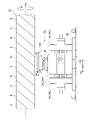
- the transport truck 4 has a second magnet 18 extending in the transport direction D1 of the holding head 2.
- the second magnet 18 extends to a range in which the holding head 2 of the transport truck 4 holds the work W and travels. Further, the second magnet 18 is arranged so as to be close to the holding head 2 traveling on the transport truck 4. The structure and operation of the second magnet 18 will be described in detail later.
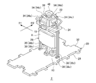
- FIG. 3 is a perspective view of the holding head 2 as viewed from diagonally above.
- FIG. 4 is a perspective view of the holding head 2 as viewed from diagonally below.
- 5 (a) is a perspective view of the vacuum pump 22, and
- FIG. 5 (b) is a sectional perspective view of the vacuum pump 22.
- the holding head 2 has a pad portion 20, a vacuum pump 22, a holding release valve 24, a support portion 26, a transport magnet 8, and a roller 10.
- the support portion 26 extends in a predetermined direction (for example, in the vertical direction), and the pad portion 20 is fixed to one end and the vacuum pump 22 is fixed to the other end. Further, the holding release valve 24, the transport magnet 8 and the roller 10 are fixed to the portion of the support portion 26 between the pad portion 20 and the vacuum pump 22.
- the pad portion 20 has a long flat plate shape in the orthogonal direction D2 orthogonal to the transport direction D1 of the holding head 2, and one main surface of the pad portion 20 faces the unit laminate manufacturing apparatus 100 in the receiving portion 12 and the delivery portion 14
- the posture is determined so as to face the stacking device 200.
- One of the main surfaces constitutes the work holding portion 28.
- the holding portion 28 of the present embodiment is composed of a suction surface that is sucked on the work W.
- the holding portion 28 is provided with a plurality of suction holes 30.
- the plurality of suction holes 30 are dispersedly arranged in the surface direction of the holding portion 28.
- the plurality of suction holes 30 are grouped into four groups: a first suction hole group 30a, a second suction hole group 30b, a third suction hole group 30c, and a fourth suction hole group 30d.
- the suction holes 30 are arranged at predetermined intervals in the orthogonal direction D2. Further, the first suction hole group 30a, the second suction hole group 30b, the third suction hole group 30c, and the fourth suction hole group 30d are arranged in this order from the front (downstream side) of the transport direction D1 of the holding head 2. I'm out.
- the suction holes 30 are connected to each other by a connecting pipe (not shown) extending in the orthogonal direction D2.
- the connecting pipe is connected to the vacuum pump 22 via a vacuum pipe 38 described later.
- a front plate 32 is provided on the main surface of the pad portion 20 opposite to the holding portion 28.
- the vacuum pump 22 is a device that generates a holding force in the holding portion 28.
- the vacuum pump 22 has a pump portion 34, a shaft portion 36, and a vacuum pipe 38.
- the vacuum pump 22 of the present embodiment is configured by a known diaphragm pump as an example.
- the structure of the vacuum pump 22 is not particularly limited as long as the holding force can be generated in the holding portion 28 by the rotation of the shaft portion 36.
- the vacuum pump 22 of the present embodiment has a plurality of pump units 34.
- the vacuum pump 22 has four pump units 34.
- Each pump unit 34 has a pump chamber 40, a diaphragm drive shaft 42, an intake port 44, and an exhaust port 46.
- the intake port 44 and the exhaust port 46 are connected to the pump chamber 40 and communicate with each other inside and outside the pump chamber 40.
- the pump chamber 40 has a diaphragm (not shown), and the diaphragm drive shaft 42 is connected to this diaphragm.
- the diaphragm drive shaft 42 is connected to the shaft portion 36.
- the shaft portion 36 operates the pump portion 34 by reciprocating the diaphragm drive shaft 42 by rotation.
- the shaft portion 36 is a so-called crankshaft.
- the diaphragm is elastically deformed by the reciprocating motion of the diaphragm drive shaft 42, whereby the atmosphere outside the pump chamber 40 is sucked into the pump chamber 40 from the intake port 44, and the atmosphere inside the pump chamber 40 is sucked into the pump chamber 40 from the exhaust port 46. It is discharged to the outside of 40.
- Each pump unit 34 is communicated with the holding unit 28 by a vacuum pipe 38, and sucks the atmosphere from each suction hole 30 of the holding unit 28.
- one end of the vacuum pipe 38 is connected to the intake port 44. Further, the other end of the vacuum pipe 38 is connected to the connecting pipe of the pad portion 20.
- the diaphragm drive shaft 42 of each pump unit 34 is connected to the same shaft unit 36. Therefore, each pump unit 34 generates a holding force by the rotation of the common shaft unit 36.
- the holding head 2 holds one work W by at least two pump units 34. Further, the holding head 2 holds a plurality of works W. As an example, of the four pump units 34, two pump units 34 hold one work W, and the remaining two pump units 34 hold another work W.
- the four pump units 34 and the first suction hole group 30a to the fourth suction hole group 30d are associated with each other on a one-to-one basis, and each suction hole group is separated from each other via the vacuum pipe 38.
- the pump unit 34 and the vacuum pipe 38 connected to the first suction hole group 30a will be referred to as a first pump unit 34a and a first vacuum pipe 38a.
- the pump portion 34 and the vacuum pipe 38 connected to the second suction hole group 30b are referred to as a second pump portion 34b and a second vacuum pipe 38b.
- the pump section 34 and the vacuum pipe 38 connected to the third suction hole group 30c are referred to as a third pump section 34c and a third vacuum pipe 38c.
- the pump unit 34 and the vacuum pipe 38 connected to the fourth suction hole group 30d are referred to as a fourth pump unit 34d and a fourth vacuum pipe 38d.
- the two works W held by each holding head 2 are arranged in the transport direction D1 of the holding head 2.
- the work W located forward in the transport direction D1 is sucked by the first suction hole group 30a and the second suction hole group 30b.
- the work W located rearward in the transport direction D1 is sucked by the third suction hole group 30c and the fourth suction hole group 30d.
- the work W located in the front is referred to as a front work W1
- the work W located in the rear is referred to as a rear work W2.
- the shaft portion 36 is provided with a first magnet 48.
- the first magnet 48 has a disk shape, and N poles and S poles are alternately magnetized around the axis of the shaft portion 36.
- the first magnet 48 is, for example, a permanent magnet.
- the shaft portion 36 can rotate by generating a magnetic force between the second magnet 18 and the first magnet 48 provided on the transport truck 4.
- FIG. 6 is a diagram illustrating a mechanism for rotating the shaft portion 36.
- the second magnet 18 is arranged close to the holding head 2 so that a magnetic force is generated between the second magnet 18 and the first magnet 48 of the held holding head 2 to be conveyed. Further, the second magnet 18 can alternately generate the magnetic force of the N pole and the magnetic force of the S pole in the transport direction D1 of the holding head 2. In the second magnet 18 of the present embodiment, N poles and S poles are alternately magnetized in the transport direction D1 of the holding head 2.
- the second magnet 18 is, for example, a permanent magnet.
- the magnetic poles of the portion of the second magnet 18 that generates a magnetic force with respect to the first magnet 48 alternate. Switch to.
- torque is generated in the shaft portion 36, and the first pump portion 34a to the fourth pump portion 34d suck the atmosphere through the holding portion 28 to generate a holding force in the holding portion 28.
- N poles and S poles are spirally formed around the rotation axis Ax extending in the transport direction D1 of the holding head 2. Further, the second magnet 18 rotates around the rotation axis Ax.
- the rotation of the second magnet 18 can be realized, for example, by the control device 16 controlling a motor (not shown) connected to the second magnet 18.
- the magnetic poles of can be switched alternately. Therefore, even when the holding head 2 is stopped, the rotation of the shaft portion 36 can be maintained and the holding force can be continuously generated in the holding portion 28.
- the rotation speed of the second magnet 18 and the transport speed of the holding head 2 are adjusted so that the magnetic pole of the portion that generates the magnetic force between the second magnet 18 and the first magnet 48 is not fixed. Further, the arrangement of the N pole and the S pole in each magnet, the positional relationship between the two magnets, and the like, which are necessary for rotating the shaft portion 36, can be appropriately set based on an experiment, a simulation, or the like by the designer. Further, the second magnet 18 shown in FIG. 1 is partially discontinuous in the range from the receiving unit 12 to the delivering unit 14. In this case, the length of the region where the second magnet 18 does not extend is the time from when the shaft portion 36 stops rotating until the holding force (adsorption force) of the holding portion 28 disappears, and the transport of the holding head 2. It is set according to the speed.
- the holding release valve 24 is a valve for releasing the holding force of the holding portion 28.
- FIG. 7 is an enlarged perspective view showing a portion of the holding head 2 including the holding release valve 24.
- 8 (a) and 8 (b) are enlarged perspective views showing a portion of the transport truck 4 including the delivery portion 14.
- FIG. 9 is a diagram illustrating an opening / closing operation of the holding release valve 24. Note that FIG. 8A omits the illustration of the laminating device 200.
- the holding release valve 24 is composed of, for example, a leaf spring, and is fixed to a long base plate 50 in the transport direction D1.
- the base plate 50 is fixed to the support portion 26 between the vacuum pump 22 and the pad portion 20.
- the vacuum pipe 38 is provided so as to penetrate the base plate 50.
- a branch pipe 52 connected to the vacuum pipe 38 is provided inside the base plate 50.
- One end of the branch pipe 52 is connected to the vacuum pipe 38, and the other end is opened to the outside of the base plate 50.
- the branch pipe 52 is connected to each of the first vacuum pipe 38a to the fourth vacuum pipe 38d.
- the branch pipe 52 connected to the first vacuum pipe 38a is referred to as a first branch pipe 52a
- the branch pipe 52 connected to the second vacuum pipe 38b is referred to as a second branch pipe 52b
- the third vacuum pipe is referred to as a third vacuum pipe.
- the branch pipe 52 connected to the 38c is referred to as a third branch pipe 52c
- the branch pipe 52 connected to the fourth vacuum pipe 38d is referred to as a fourth branch pipe 52d.
- two open ends of the branch pipes 52 are arranged on both sides of the base plate 50 in the orthogonal direction D2. Further, on each side of the base plate 50, the two open ends are arranged side by side in the transport direction D1. An open end of the first branch pipe 52a is arranged in front of the transport direction D1 on one side of the base plate 50. An open end of the third branch pipe 52c is arranged behind the transport direction D1 on one side of the base plate 50. An open end of the second branch pipe 52b is arranged in front of the transport direction D1 on the other side of the base plate 50. The open end of the fourth branch pipe 52d is arranged behind the transport direction D1 on the other side of the base plate 50.
- each branch pipe 52 is closed by the holding release valve 24.
- one long leaf spring is fixed to each side of the base plate 50 in the orthogonal direction D2 in the transport direction D1. Then, both ends of each leaf spring close the open end of the branch pipe 52, respectively, and function as a holding release valve 24.
- the work is switched between a closed state (a state in which the open end of the branch pipe 52 is closed) and an open state (a state in which the open end of the branch pipe 52 communicates with the atmosphere). W can be retained and released.
- the holding / releasing valve 24 that closes the open end of the first branch pipe 52a is referred to as the first holding / releasing valve 24a
- the holding / releasing valve 24 that closes the open end of the second branch pipe 52b is referred to as the second holding / releasing valve 24b
- the holding / releasing valve 24 that closes the open end of the third branch pipe 52c is referred to as a third holding / releasing valve 24c
- the holding / releasing valve 24 that closes the open end of the fourth branch pipe 52d is referred to as a fourth holding / releasing valve 24d.
- the front work W1 is switched between holding and releasing by the first holding release valve 24a and the second holding release valve 24b.
- the rear work W2 is switched between holding and releasing by the third holding release valve 24c and the fourth holding release valve 24d.
- Each holding release valve 24 has a third magnet 54 on a surface facing outward in the orthogonal direction D2.
- the third magnet 54 is, for example, a permanent magnet.
- the third magnet 54 is provided at both ends of the leaf spring constituting the first holding release valve 24a and the third holding release valve 24c.
- third magnets 54 are provided at both ends of the leaf springs constituting the second holding release valve 24b and the fourth holding release valve 24d.
- the transport truck 4 has a fourth magnet 56 at a position where the holding head 2 discharges the work W, that is, at the delivery portion 14.
- the fourth magnet 56 is, for example, an electromagnet.
- the energization of the fourth magnet 56 and the interruption of the energization are controlled by, for example, the control device 16.
- the fourth magnet 56 is arranged so as to generate a magnetic force with the third magnet 54 provided on the holding head 2 that has reached the delivery portion 14.
- the holding release valve 24 switches between the open / closed state due to the generation of a magnetic force between the third magnet 54 and the fourth magnet 56.
- a magnetic force that attracts each other is generated between the third magnet 54 and the fourth magnet 56.
- the leaf spring constituting the holding release valve 24 is elastically deformed in a direction away from the base plate 50. That is, the holding release valve 24 is in an open state.
- a gap G is formed between the base plate 50 and the leaf spring, and the open end of the branch pipe 52 communicates with the atmosphere.
- the atmosphere is sucked into the vacuum pipe 38 via the branch pipe 52, and the holding force (adsorption force) of the holding portion 28 is released.
- the holding force absorption force
- the leaf spring returns to the original state and closes the open end of the branch pipe 52. That is, the holding release valve 24 is in a closed state. As a result, the holding force of the holding portion 28 is restored.
- the fourth magnet 56 is arranged one by one at each delivery portion 14 so as to sandwich the holding head 2 in the orthogonal direction D2. Further, the two fourth magnets 56 arranged in each delivery portion 14 are arranged so as to be offset in the transport direction D1. Specifically, the fourth magnet 56 facing each open end of the first branch pipe 52a and the third branch pipe 52c is a fourth magnet facing each open end of the second branch pipe 52b and the fourth branch pipe 52d. It is displaced backward (upstream side) in the transport direction D1 from 56. Therefore, the release of the suction of the front work W1 by the first suction hole group 30a occurs before the release of the suction of the front work W1 by the second suction hole group 30b. Further, the release of the suction of the rear work W2 by the third suction hole group 30c occurs before the release of the suction of the rear work W2 by the fourth suction hole group 30d.
- the first holding release valve 24a first opens.
- vacuum fracture occurs in the front portion of the front work W1, and the front portion is handed over to the laminating device 200.
- the second holding release valve 24b opens.
- vacuum fracture occurs in the rear portion of the front work W1, and the rear portion is handed over to the laminating device 200.
- the control device 16 releases the energization to the fourth magnet 56 until the holding head 2 finishes passing through the delivery portion 14 on the upstream side.
- the holding head 2 advances to the delivery section 14 on the downstream side while sucking and holding the rear work W2. Then, the third holding release valve 24c is opened at the delivery portion 14 on the downstream side, the front portion of the rear work W2 is delivered to the laminating device 200, and then the fourth holding release valve 24d is opened.
- the rear portion of the side work W2 is delivered to the laminating device 200.
- the rear work W2 may be delivered to the laminating device 200 at the upstream delivery section 14, and the front work W1 may be delivered to the laminating device 200 at the downstream delivery section 14.
- the work transfer device 1 has a holding portion 28 of the work W, a plurality of holding heads 2 having a vacuum pump 22 for generating a holding force in the holding portion 28, and a plurality of holding portions.
- a transport truck 4 for transporting the head 2 is provided.
- the vacuum pump 22 has a pump unit 34 that communicates with the holding unit 28 and sucks the atmosphere through the holding unit 28, and a shaft portion 36 that operates the pump unit 34 by rotation.
- the shaft portion 36 has a first magnet 48 in which the north pole and the south pole are alternately magnetized around the shaft.
- the transport truck 4 is a second magnet 18 extending in the transport direction D1 of the holding head 2, and alternately generates the magnetic force of the N pole and the magnetic force of the S pole in the transport direction D1 of the holding head 2. It has a second magnet 18 arranged so as to generate a magnetic force with the first magnet 48. Then, the magnetic poles of the portion of the second magnet 18 that generates a magnetic force with respect to the first magnet 48 are alternately switched to rotate the shaft portion 36, whereby the pump portion 34 attracts the atmosphere to generate a holding force. Let me.
- the vacuum pump 22 is mounted on the holding head 2, and the holding force is generated in the holding portion 28 by rotating the shaft portion 36 by the action of the first magnet 48 and the second magnet 18. I'm letting you. For this reason, the vacuum piping and wiring required when the vacuum pump and the drive power supply are left outside to move the holding head, or when the drive power supply is left outside to move the holding head equipped with the vacuum pump. The laying can be omitted. Therefore, the degree of freedom in designing the work transfer device 1 can be increased.
- the second magnet 18 of the present embodiment rotates around the rotation axis Ax extending in the transport direction D1, and the N pole and the S pole are spirally formed around the rotation axis Ax. Then, as the second magnet 18 rotates, the magnetic poles of the portion of the second magnet 18 that generates a magnetic force with respect to the first magnet 48 are alternately switched. As a result, even if the holding head 2 is stopped, the holding force of the holding portion 28 can be maintained by continuing to rotate the shaft portion 36. For example, when the delivery surface of the work W and the holding portion 28 are both flat, it is desirable to stop the holding head 2 to transfer the work W in order to reduce the load applied to the work W at the time of delivery. ..
- the holding head 2 of the present embodiment capable of receiving the work W in the stopped state, the work W can be exchanged between the planes while reducing the load on the work W. If the work W is transferred between curved surfaces or between a curved surface and a flat surface, the work W can be transferred with a light load even while the holding head 2 is moved.
- the vacuum pump 22 of the present embodiment has a plurality of pump units 34.
- the holding portion 28 can be divided into a plurality of regions, and the holding force can be independently generated in each region. Further, the area of the holding portion 28 can be increased and the holding force can be increased. Further, each pump unit 34 operates by the rotation of the common shaft unit 36 to generate an suction force. As a result, it is possible to prevent the structure of the holding head 2 from becoming complicated due to the increase in the pump portion 34.
- the number of pump units 34 may be only one or a plurality of pump units other than four.
- the holding head 2 of the present embodiment holds one work W by at least two pump units 34. Further, the holding head 2 holds a plurality of works W. Specifically, the front work W1 is held by the first pump unit 34a and the second pump unit 34b. Further, the rear work W2 is held by the third pump unit 34c and the fourth pump unit 34d. By holding one work W by two or more pump units 34, the work W can be discharged in a plurality of stages. As a result, when the work W is delivered to the laminating device 200, the work W can be delivered more accurately. Further, the holding head 2 holds a plurality of work Ws, so that the throughput of the work transfer device 1 can be improved. One work W may be held by one pump unit 34 or three or more pump units 34. Further, the holding head 2 may hold one work W or three or more work Ws.
- the holding head 2 of the present embodiment has a holding release valve 24 that releases the holding force of the holding portion 28.
- the holding release valve 24 has a third magnet 54.
- the transport truck 4 has a fourth magnet 56 arranged so that a magnetic force is generated between the holding head 2 and the third magnet 54 at a position where the holding head 2 discharges the work W.
- the holding release valve 24 releases the holding force by switching the open / closed state by generating a magnetic force between the third magnet 54 and the fourth magnet 56.
- the holding force of the holding portion 28 can be released by a simple mechanism. Therefore, it is possible to suppress the increase in size of the vacuum pump 22 and thus the holding head 2.
- the transport truck 4 of the present embodiment is branched into a plurality of parts. As a result, the degree of freedom in arranging the transfer destination of the work W can be increased. Further, by arranging a device having a fast tact time at the branch source of the transport truck 4 and arranging a device having a slow tact time at each of the branch destinations, it is possible to avoid sacrificing the production speed of the device having a fast tact time. ..
- the work W of the present embodiment is a unit laminated body 300 in which an electrode plate and a separator are laminated.
- the transport truck 4 has a receiving unit 12 in which the holding head 2 receives the unit laminated body 300 from the unit laminated body manufacturing apparatus 100, and a delivery unit 14 in which the holding head 2 discharges the unit laminated body 300 to the laminating device 200. ..
- a plurality of delivery units 14 are provided for one receiving unit 12.
- the tact time of the unit laminated body manufacturing apparatus 100 (time required for manufacturing the unit laminated body 300 and handing it over to the holding head 2) is the tact time of the laminated body 200 (manufacturing of the laminated electrode body 302 and taking out from the laminated stage 200b). It tends to be shorter than the time required). Therefore, by providing a plurality of delivery units 14 for one receiving unit 12, the production speed of the laminated electrode body 302 can be improved. Further, a delivery section 14 is arranged at each branch destination of the transport truck 4. As a result, it is possible to suppress the lengthening of the transport truck 4 as compared with the case where a plurality of delivery portions 14 are arranged in series.
- the work transfer device 1 of the present embodiment it is possible to generate power by using the rotation of the shaft portion 36.
- the electric power obtained from this power generation can be used, for example, as a drive source for various sensors mounted on the holding head 2.
- the second embodiment has substantially the same configuration as the first embodiment except for the structure of the second magnet 18.
- the present embodiment will be mainly described with a configuration different from that of the first embodiment, and the common configuration will be briefly described or omitted.
- FIG. 10 is a diagram illustrating a mechanism for rotating the shaft portion 36 in the work transfer device 1 according to the second embodiment.
- the second magnet 18 of the present embodiment alternately generates the magnetic force of the N pole and the magnetic force of the S pole in the transport direction D1 of the holding head 2.
- N poles and S poles are alternately magnetized in the transport direction D1 of the holding head 2.
- the second magnet 18 of the present embodiment does not rotate around the rotation axis Ax. Even in such a configuration, the magnetic poles of the portion of the second magnet 18 that generates a magnetic force with respect to the first magnet 48 are alternately switched by the transport (movement) of the holding head 2.
- the shaft portion 36 can be rotated to operate the first pump portion 34a to the fourth pump portion 34d.
- the work transfer device 1 of the present embodiment can also increase the degree of freedom in designing the work transfer device 1. Further, in the work transfer device 1 of the present embodiment, it is necessary to keep moving the holding head 2 in order to maintain the holding force of the holding portion 28, but since the mechanism for rotating the second magnet 18 can be omitted, the work.
- the structure of the transport device 1 can be simplified.
- the pump unit 34 sucks the atmosphere through the holding unit 28 to generate an adsorption force as the holding force, but the present invention is not limited to this, and the pump unit 34 is applied to the holding unit 28.
- the holding force may be generated by discharging the atmosphere.
- the holding portion 28 is composed of a driving mechanism such as a cylinder driven by pressurization, and a gripping claw or the like that switches between gripping and releasing of the work W by this driving mechanism. Then, the exhaust port 46 and the holding portion 28 of the pump portion 34 are communicated with each other by the vacuum pipe 38.
- the pump unit 34 is driven, the atmosphere is discharged to the holding unit 28 and the drive mechanism is pressurized.
- the gripping claw grips the work W. That is, the pump unit 34 can generate a holding force in the holding unit 28 by discharging the atmosphere to the holding unit 28.
- the second magnet 18 of the first and second embodiments is a permanent magnet in which N pole and S pole are alternately magnetized in the transport direction D1 of the holding head 2, but the second magnet 18 is not limited to this. It may be composed of an electromagnet.
- FIG. 11 is a perspective view of a part of the second magnet 18 included in the work transfer device 1 according to the modified example 2.
- the second magnet 18 of the second modification has a structure in which a plurality of substantially U-shaped magnetic members 60 around which the coil 58 is wound are arranged in the transport direction D1.
- a magnetic force is generated in the first end portion 60a and the second end portion 60b by energizing the coil 58 wound around the intermediate portion.
- the first end portion 60a of each magnetic member 60 is arranged so as to be continuous in the transport direction D1 and to generate a magnetic force between the first magnet 48 of the holding head 2 to be transported.
- the coils 58 are energized so that the magnetic forces of different magnetic poles are generated at the adjacent first end portions 60a.
- the second magnet 18 can alternately generate the magnetic force of the N pole and the magnetic force of the S pole in the transport direction D1 of the holding head 2.
- the energization of each coil 58 is controlled by, for example, a control device 16.
- This disclosure can be used for work transfer equipment.
- 1 work transfer device 2 holding head, 4 transfer track, 12 receiving part, 14 delivery part, 18 second magnet, 22 vacuum pump, 24 holding release valve, 28 holding part, 34 pump part, 36 shaft part, 48 first Magnet, 54 3rd magnet, 56 4th magnet, W work.
Landscapes
- Engineering & Computer Science (AREA)
- Manufacturing & Machinery (AREA)
- Chemical & Material Sciences (AREA)
- Chemical Kinetics & Catalysis (AREA)
- Electrochemistry (AREA)
- General Chemical & Material Sciences (AREA)
- Mechanical Engineering (AREA)
- Feeding Of Articles By Means Other Than Belts Or Rollers (AREA)
- Specific Conveyance Elements (AREA)
- Manipulator (AREA)
Abstract
ワーク搬送装置(1)は、ワーク(W)の保持部および保持力を発生させる真空ポンプ(22)を有する複数の保持ヘッド(2)と、複数の保持ヘッド(2)を搬送する搬送トラック(4)を備える。真空ポンプ(22)は、保持部に連通されて雰囲気を吸引または吐出するポンプ部(34)と、回転によりポンプ部(34)を稼働させる軸部(36)と有する。軸部(36)は、N極とS極とが軸周りに交互に着磁された第1磁石(48)を有する。搬送トラックは、保持ヘッドの搬送方向(D1)に延びる第2磁石(18)であって、搬送方向(D1)にN極の磁力とS極の磁力とを交互に発生させるとともに、保持ヘッドの第1磁石(48)との間に磁力が発生するように配置される第2磁石(18)を有する。第2磁石(18)における第1磁石(48)に対して磁力を発生させる部分の磁極が交互に切り替わることで軸部(36)が回転し、ポンプ部(34)が保持力を発生させる。
Description
本開示は、ワーク搬送装置に関する。
車載用等の電池として、積層ラミネートタイプの電池が開発されている。この電池は、複数の正極板および複数の負極板がセパレータを挟んで交互に積層された積層電極体と、電解液とが容器に収容された構造を有する。このような積層型電池の製造について、例えば特許文献1には、電極やセパレータの個片を吸着パッドで真空吸着して積層ステージまで搬送し、ステージ上に積層していくことが開示されている。このような搬送方法は、電極板やセパレータに限らず他のワークを搬送する場合にも採用され得る。
真空吸着では吸着パッドと真空ポンプとを真空配管で接続する必要がある。また、真空ポンプと駆動電源とを配線で接続する必要がある。したがって、真空ポンプや駆動電源を外部に据え置いて吸着パッドを移動させる場合、電極板等の搬送距離が長かったり、搬送経路が複雑(例えば分岐や合流等が含まれる場合)であったりすると、真空配管や配線が絡み合ってしまうおそれがある。このため、真空配管や配線の敷設が制約となって、ワーク搬送装置の設計自由度が制限されていた。
本開示はこうした状況に鑑みてなされたものであり、その目的の1つは、ワーク搬送装置の設計自由度を高める技術を提供することにある。
本開示のある態様は、ワーク搬送装置である。この装置は、ワークの保持部、および保持部に保持力を発生させる真空ポンプを有する複数の保持ヘッドと、複数の保持ヘッドを搬送する搬送トラックと、を備える。真空ポンプは、保持部に連通されて保持部を介して雰囲気を吸引、または保持部に雰囲気を吐出するポンプ部と、回転によりポンプ部を稼働させる軸部と、有する。軸部は、N極とS極とが軸周りに交互に着磁された第1磁石を有する。搬送トラックは、保持ヘッドの搬送方向に延びる第2磁石であって、搬送方向にN極の磁力とS極の磁力とを交互に発生させるとともに、搬送される保持ヘッドの第1磁石との間に磁力が発生するように配置される第2磁石を有する。第2磁石における第1磁石に対して磁力を発生させる部分の磁極が交互に切り替わることで軸部が回転し、ポンプ部が雰囲気を吸引または吐出することで保持力を発生させる。
以上の構成要素の任意の組合せ、本開示の表現を方法、装置、システムなどの間で変換したものもまた、本開示の態様として有効である。
本開示によれば、ワーク搬送装置の設計自由度を高めることができる。
以下、本開示を好適な実施の形態をもとに図面を参照しながら説明する。実施の形態は、本開示を限定するものではなく例示であって、実施の形態に記述されるすべての特徴やその組み合わせは、必ずしも本開示の本質的なものであるとは限らない。各図面に示される同一または同等の構成要素、部材、処理には、同一の符号を付するものとし、適宜重複した説明は省略する。また、各図に示す各部の縮尺や形状は、説明を容易にするために便宜的に設定されており、特に言及がない限り限定的に解釈されるものではない。また、本明細書または請求項中に「第1」、「第2」等の用語が用いられる場合には、特に言及がない限りこの用語はいかなる順序や重要度を表すものでもなく、ある構成と他の構成とを区別するためのものである。また、各図面において実施の形態を説明する上で重要ではない部材の一部は省略して表示する。
(実施の形態1)
図1は、実施の形態1に係るワーク搬送装置1の斜視図である。図2は、ワーク搬送装置1の一部分を拡大して示す斜視図である。なお、図2では、保持ヘッド2の表板32の図示を省略している。
図1は、実施の形態1に係るワーク搬送装置1の斜視図である。図2は、ワーク搬送装置1の一部分を拡大して示す斜視図である。なお、図2では、保持ヘッド2の表板32の図示を省略している。
ワーク搬送装置1は、複数の保持ヘッド2と、搬送トラック4とを備える。本実施の形態の各保持ヘッド2は、雰囲気の吸引により発生する吸着力によってワークWを吸着保持する。一例としてのワークWは、電池の電極板およびセパレータの少なくとも一方を含む。本実施の形態のワークWは、電極板およびセパレータが積層された単位積層体300である。単位積層体300は、積層電極体302の構成単位である。つまり、複数の単位積層体300が積層されて積層電極体302が得られる。なお、ワークWは、電極板、セパレータ、単位積層体300といった電池の構成部品に限定されない。
搬送トラック4は、複数の保持ヘッド2を搬送する機構である。各保持ヘッド2は、搬送トラック4をガイドレールとして、搬送トラック4上を走行する。搬送トラック4は、各保持ヘッド2を搬送する公知の搬送機構を有する。本実施の形態の搬送トラック4は、一例として公知のリニア搬送機構を有する。具体的には、搬送トラック4は、延在方向に配列される複数のコイル(図示せず)を内蔵するレール部6(固定子)を有する。また、各保持ヘッド2(可動子)は、レール部6に懸下された状態でコイルと対向する位置に、搬送用磁石8を有する。搬送用磁石8は、例えば永久磁石である。
各コイルへの通電により生じる磁束を搬送用磁石8に作用させることで、保持ヘッド2にはレール部6に沿う推力と、レール部6に対する吸引力とが発生する。これにより、保持ヘッド2はレール部6に沿って走行する。保持ヘッド2は、レール部6に摺動可能に接するローラ10を有し、ローラ10によってレール部6に対する距離が維持される。リニア搬送機構は公知であるため、これ以上の詳細な説明は省略する。なお、搬送トラック4は、例えばチェーン等で保持ヘッド2を牽引する、リニア搬送機構以外の搬送機構を備えてもよい。
本実施の形態の搬送トラック4は、複数に分岐している。また、搬送トラック4は、受取部12と、受渡部14とを有する。保持ヘッド2は、受取部12において、単位積層体製造装置100から単位積層体300を受け取る。また、保持ヘッド2は、受渡部14において、積層装置200に対して単位積層体300を放出する。積層装置200は、複数の単位積層体300を積層して積層電極体302を製造する装置である。また、受渡部14は、1つの受取部12に対して複数設けられる。なお、図1では、単位積層体製造装置100および積層装置200を模式的に図示しており、一部の構造の図示を省略している。また、各装置の構造は図示したものに限定されない。
一例として搬送トラック4は、所定方向に長い環状構造を有し、環の一部は並列に延びる2つの軌道に分かれている。つまり、搬送トラック4は、1本の第1軌道4aと、第1軌道4aの一端から分岐する第2軌道4bおよび第3軌道4cとを有する。第1軌道4aから分岐した第2軌道4bおよび第3軌道4cは、他端側が第1軌道4aに合流する。つまり、第1軌道4aの一端に分岐点4dが設けられ、第1軌道4aの他端に合流点4eが設けられる。第1軌道4aには、受取部12が配置される。第2軌道4bおよび第3軌道4cには、それぞれ2つの受渡部14が配置される。第2軌道4bおよび第3軌道4cのそれぞれにおいて、2つの受渡部14は直列に並ぶ。なお、搬送トラック4の形状は特に限定されず、分岐点4dや合流点4eを有しなくてもよいし、2つ以上の分岐点4dや合流点4eを有してもよい。
保持ヘッド2は、受取部12において単位積層体製造装置100からワークWとしての単位積層体300を受け取り、第1軌道4aを走行する。第2軌道4bと第3軌道4cへの分岐点4dに到達した保持ヘッド2は、制御装置16によって第2軌道4bまたは第3軌道4cのいずれかに進行させられる。制御装置16は、レール部6に内蔵されるコイルへの通電を制御することで、保持ヘッド2の進行先を切り替えることができる。制御装置16は、ハードウェア構成としてはコンピュータのCPUやメモリをはじめとする素子や回路で実現され、ソフトウェア構成としてはコンピュータプログラム等によって実現されるが、図1では、それらの連携によって実現される機能ブロックとして描いている。この機能ブロックがハードウェアおよびソフトウェアの組合せによっていろいろなかたちで実現できることは、当業者には当然に理解されるところである。
第2軌道4bあるいは第3軌道4cを進行する保持ヘッド2は、受渡部14において積層装置200に単位積層体300を受け渡す。単位積層体300を放出した保持ヘッド2は、第2軌道4bあるいは第3軌道4cをさらに進行して合流点4eから第1軌道4aに戻り、再び受取部12に到達する。そして、受取部12で単位積層体300を受け取って、受渡部14に向けて搬送される。
単位積層体製造装置100は、一例として複数のドラムを組み合わせた連続ドラム式の製造装置であり、電極体やセパレータの切断、加熱、接着、積層等の各工程をドラムで実行する。これにより、高速且つ連続的に単位積層体300を製造することができる。単位積層体製造装置100では、第1極切断ドラム100aによって、個片化された複数の第1電極板304が得られる。また、第2極切断ドラム100bによって、個片化された複数の第2電極板306が得られる。
第1電極板304および第2電極板306は、それぞれ予備加熱されて接着ドラム100cに供給される。また、接着ドラム100cには、第1セパレータ308の連続体および第2セパレータ310の連続体が供給される。そして、接着ドラム100cにおいて、第1セパレータ308の連続体、複数の第1電極板304、第2セパレータ310の連続体および複数の第2電極板306がこの順に積層されて圧着され、複数の単位積層体300が連続する連続積層体が形成される。連続積層体は、セパレータ切断ドラム100dによって複数の単位積層体300に個片化される。個片化された単位積層体300は、受取部12に搬送されて保持ヘッド2に受け渡される。
単位積層体300は、受渡部14において保持ヘッド2から積層装置200に受け渡される。積層装置200は、積層ドラム200aを備える。積層ドラム200aは、保持ヘッド2から受け取った複数の単位積層体300を積層ステージ200bに順次搬送し、積層ステージ200bに放出する。これにより、積層ステージ200b上で単位積層体300が積み重ねられて、積層電極体302が得られる。形成された積層電極体302は、次工程の装置に向けて積層ステージ200bから取り出される。なお、単位積層体300は、保持ヘッド2から積層ドラム200aに直に受け渡されてもよいし、保持ヘッド2と積層ドラム200aとの間に中継ドラムが介在してもよい。
また、搬送トラック4は、保持ヘッド2の搬送方向D1に延びる第2磁石18を有する。第2磁石18は、搬送トラック4のうち保持ヘッド2がワークWを保持して走行する範囲に延在している。また、第2磁石18は、搬送トラック4を走行する保持ヘッド2に近接するように配置される。第2磁石18の構造や作用については、後に詳細に説明する。
図3は、斜め上から見た保持ヘッド2の斜視図である。図4は、斜め下から見た保持ヘッド2の斜視図である。図5(a)は真空ポンプ22の斜視図であり、図5(b)は真空ポンプ22の断面斜視図である。保持ヘッド2は、パッド部20と、真空ポンプ22と、保持解除バルブ24と、支持部26と、搬送用磁石8と、ローラ10とを有する。支持部26は、所定方向(例えば鉛直方向)に延びており、一端にパッド部20が固定され、他端に真空ポンプ22が固定される。また、支持部26におけるパッド部20と真空ポンプ22との間の部分に、保持解除バルブ24、搬送用磁石8およびローラ10が固定される。
パッド部20は、保持ヘッド2の搬送方向D1と直交する直交方向D2に長尺の平板状であり、一方の主表面が受取部12において単位積層体製造装置100と対向し、また受渡部14において積層装置200と対向するように姿勢が定められる。この一方の主表面は、ワークの保持部28を構成する。本実施の形態の保持部28は、ワークWに吸着する吸着面で構成される。保持部28には、複数の吸着穴30が設けられる。複数の吸着穴30は、保持部28の面方向に分散して配置される。
複数の吸着穴30は、第1吸着穴群30a、第2吸着穴群30b、第3吸着穴群30cおよび第4吸着穴群30dの4つにグループ化されている。各吸着穴群において、吸着穴30は直交方向D2に所定の間隔をあけて配置される。また、第1吸着穴群30a、第2吸着穴群30b、第3吸着穴群30cおよび第4吸着穴群30dは、この順序で保持ヘッド2の搬送方向D1の前方(下流側)から順に並んでいる。各吸着穴群において、吸着穴30は直交方向D2に延びる連結配管(図示せず)によって互いに接続される。連結配管は、後述する真空配管38を介して真空ポンプ22に接続される。パッド部20の保持部28とは反対側の主表面には、表板32が設けられる。
真空ポンプ22は、保持部28に保持力を発生させる装置である。真空ポンプ22は、ポンプ部34と、軸部36と、真空配管38とを有する。本実施の形態の真空ポンプ22は、一例として公知のダイヤフラムポンプで構成される。なお、真空ポンプ22は、軸部36の回転によって保持部28に保持力を発生させられるものであれば、その構造は特に限定されない。
本実施の形態の真空ポンプ22は、複数のポンプ部34を有する。一例として、真空ポンプ22は、4つのポンプ部34を有する。各ポンプ部34は、ポンプ室40と、ダイヤフラム駆動軸42と、吸気口44と、排気口46とを有する。吸気口44および排気口46は、ポンプ室40に接続されてポンプ室40の内外を連通する。また、ポンプ室40はダイヤフラム(図示せず)を有し、このダイヤフラムにダイヤフラム駆動軸42が接続される。ダイヤフラム駆動軸42は、軸部36に接続される。
軸部36は、回転によりダイヤフラム駆動軸42を往復運動させることで、ポンプ部34を稼働させる。軸部36は、いわゆるクランクシャフトである。ダイヤフラム駆動軸42が往復運動することでダイヤフラムが弾性変形し、これによりポンプ室40外の雰囲気が吸気口44からポンプ室40内に吸い込まれ、ポンプ室40内の雰囲気が排気口46からポンプ室40外に排出される。
各ポンプ部34は、真空配管38によって保持部28に連通されて、保持部28の各吸着穴30から雰囲気を吸引する。具体的には、真空配管38の一端が吸気口44に接続される。また、真空配管38の他端がパッド部20の連結配管に接続される。これにより、軸部36の回転によって各ポンプ部34が稼働すると、吸着穴30から雰囲気が吸い込まれて保持部28に吸着力、つまり保持力が発生する。各ポンプ部34のダイヤフラム駆動軸42は、同じ軸部36に連結される。したがって、各ポンプ部34は、共通の軸部36の回転によって保持力を発生させる。
保持ヘッド2は、少なくとも2つのポンプ部34によって1つのワークWを保持する。また、保持ヘッド2は、複数のワークWを保持する。一例として、4つのポンプ部34のうち、2つのポンプ部34によって1つのワークWを保持し、残り2つのポンプ部34によって別の1つのワークWを保持する。
具体的には、4つのポンプ部34と第1吸着穴群30a~第4吸着穴群30dとが1対1で対応付けられ、各吸着穴群が真空配管38を介して別々のポンプ部34に接続される。以下では適宜、第1吸着穴群30aに接続されるポンプ部34および真空配管38を第1ポンプ部34aおよび第1真空配管38aという。また、第2吸着穴群30bに接続されるポンプ部34および真空配管38を第2ポンプ部34bおよび第2真空配管38bという。また、第3吸着穴群30cに接続されるポンプ部34および真空配管38を第3ポンプ部34cおよび第3真空配管38cという。また、第4吸着穴群30dに接続されるポンプ部34および真空配管38を第4ポンプ部34dおよび第4真空配管38dという。
各保持ヘッド2が保持する2つのワークWは、保持ヘッド2の搬送方向D1に配列される。搬送方向D1で前方に位置するワークWは、第1吸着穴群30aおよび第2吸着穴群30bで吸着される。搬送方向D1で後方に位置するワークWは、第3吸着穴群30cおよび第4吸着穴群30dで吸着される。以下では適宜、前方に位置するワークWを前側ワークW1といい、後方に位置するワークWを後側ワークW2という。
軸部36には、第1磁石48が設けられる。第1磁石48は円盤状であり、N極とS極とが軸部36の軸周りに交互に着磁されている。第1磁石48は、例えば永久磁石である。軸部36は、搬送トラック4に設けられる第2磁石18と第1磁石48との間に磁力が発生することで回転することができる。
図6は、軸部36を回転させる機構を説明する図である。図6に示すように、第2磁石18は、搬送される保持ヘッド2の第1磁石48との間に磁力が発生するように、保持ヘッド2に対して近接配置される。また、第2磁石18は、保持ヘッド2の搬送方向D1にN極の磁力とS極の磁力とを交互に発生させることができる。本実施の形態の第2磁石18は、保持ヘッド2の搬送方向D1にN極とS極とが交互に着磁されている。第2磁石18は、例えば永久磁石である。これにより、保持ヘッド2が搬送されると、第2磁石18における第1磁石48に対して磁力を発生させる部分(例えば、第2磁石18において最も第1磁石48に近い部分)の磁極が交互に切り替わる。この結果、軸部36にトルクが生じて、第1ポンプ部34a~第4ポンプ部34dが保持部28を介して雰囲気を吸引し、保持部28に保持力を発生させる。
また、本実施の形態の第2磁石18は、保持ヘッド2の搬送方向D1に延びる回転軸Ax周りにN極およびS極が螺旋状に形成されている。また、第2磁石18は、回転軸Ax周りに回転する。第2磁石18の回転は、例えば第2磁石18に接続されるモータ(図示せず)を制御装置16が制御することで実現できる。N極とS極とが螺旋状に形成された第2磁石18を回転させることで、保持ヘッド2が停止している状態においても、第2磁石18における第1磁石48に磁力を発生させる部分の磁極を交互に切り替えることができる。したがって、保持ヘッド2が停止している状態でも、軸部36の回転を維持して保持部28に保持力を発生させ続けることができる。
なお、第2磁石18の回転速度と保持ヘッド2の搬送速度とは、第2磁石18と第1磁石48との間で磁力を発生させる部分の磁極が固定されないように調整される。また、軸部36を回転させるために必要な、各磁石におけるN極およびS極の配置や両磁石の位置関係等は、設計者による実験やシミュレーション等に基づき適宜設定することができる。また、図1に示す第2磁石18は、受取部12から受渡部14までの範囲で一部が不連続になっている。この場合、第2磁石18が延在しない領域の長さは、軸部36が回転を停止してから保持部28の保持力(吸着力)が消失するまでの時間と、保持ヘッド2の搬送速度とに応じて設定される。
保持解除バルブ24は、保持部28の保持力を解除するための弁である。図7は、保持ヘッド2の保持解除バルブ24を含む部分を拡大して示す斜視図である。図8(a)および図8(b)は、搬送トラック4の受渡部14を含む部分を拡大して示す斜視図である。図9は、保持解除バルブ24の開閉動作を説明する図である。なお、図8(a)では、積層装置200の図示を省略している。
図7に示すように、保持解除バルブ24は例えば板ばねで構成され、搬送方向D1に長いベース板50に固定される。ベース板50は、真空ポンプ22とパッド部20との間で支持部26に固定される。真空配管38は、ベース板50を貫通するように設けられる。ベース板50の内部には、真空配管38に接続される枝配管52が設けられる。枝配管52は、一端が真空配管38に接続され、他端がベース板50の外部に開放される。本実施の形態では、第1真空配管38a~第4真空配管38dのそれぞれに対して枝配管52が接続される。以下では適宜、第1真空配管38aに接続される枝配管52を第1枝配管52aといい、第2真空配管38bに接続される枝配管52を第2枝配管52bといい、第3真空配管38cに接続される枝配管52を第3枝配管52cといい、第4真空配管38dに接続される枝配管52を第4枝配管52dという。
また本実施の形態では、直交方向D2におけるベース板50の両側に2つずつ枝配管52の開放端が配置される。また、ベース板50の各側において、2つの開放端は搬送方向D1に並んで配置される。ベース板50の一方側における搬送方向D1の前方には、第1枝配管52aの開放端が配置される。ベース板50の一方側における搬送方向D1の後方には、第3枝配管52cの開放端が配置される。ベース板50の他方側における搬送方向D1の前方には、第2枝配管52bの開放端が配置される。ベース板50の他方側における搬送方向D1の後方には、第4枝配管52dの開放端が配置される。
各枝配管52の開放端は、保持解除バルブ24で塞がれる。本実施の形態では、直交方向D2におけるベース板50の両側に、搬送方向D1に長い板ばねがそれぞれ1枚ずつ固定される。そして、各板ばねの両端部がそれぞれ枝配管52の開放端を塞いで、保持解除バルブ24として機能する。各保持解除バルブ24が閉じた状態(枝配管52の開放端が塞がれた状態)と開いた状態(枝配管52の開放端が大気に連通する状態)との間で切り替わることで、ワークWを保持したり放出したりすることができる。以下では適宜、第1枝配管52aの開放端を塞ぐ保持解除バルブ24を第1保持解除バルブ24aといい、第2枝配管52bの開放端を塞ぐ保持解除バルブ24を第2保持解除バルブ24bといい、第3枝配管52cの開放端を塞ぐ保持解除バルブ24を第3保持解除バルブ24cといい、第4枝配管52dの開放端を塞ぐ保持解除バルブ24を第4保持解除バルブ24dという。
前側ワークW1は、第1保持解除バルブ24aおよび第2保持解除バルブ24bによって保持と放出とが切り替えられる。後側ワークW2は、第3保持解除バルブ24cおよび第4保持解除バルブ24dによって、保持と放出とが切り替えられる。
各保持解除バルブ24は、直交方向D2で外側を向く面に第3磁石54を有する。第3磁石54は、例えば永久磁石である。本実施の形態では、第1保持解除バルブ24aおよび第3保持解除バルブ24cを構成する板ばねの両端部に第3磁石54が設けられる。同様に、第2保持解除バルブ24bおよび第4保持解除バルブ24dを構成する板ばねの両端部に第3磁石54が設けられる。
図8(a)および図8(b)に示すように、搬送トラック4は、保持ヘッド2がワークWを放出する位置、つまり受渡部14に第4磁石56を有する。第4磁石56は、例えば電磁石である。第4磁石56への通電と通電の遮断とは、例えば制御装置16によって制御される。第4磁石56は、受渡部14に到達した保持ヘッド2に設けられる第3磁石54との間で磁力が発生するように配置される。
図9に示すように、保持解除バルブ24は、第3磁石54と第4磁石56との間に磁力が発生することで開閉状態が切り替わる。本実施の形態では、第3磁石54と第4磁石56との間に互いに引き付け合う磁力が発生する。両磁石間に磁力が発生すると、保持解除バルブ24を構成する板ばねは、ベース板50から離間する方向に弾性変形する。つまり、保持解除バルブ24が開いた状態となる。これにより、ベース板50と板ばねとの間に隙間Gが形成され、枝配管52の開放端が大気と連通する。この結果、枝配管52を介して真空配管38に大気が吸引されて、保持部28の保持力(吸着力)が解除される。第3磁石54と第4磁石56との間の磁力が消失すると、板ばねは元の状態に戻って枝配管52の開放端を塞ぐ。つまり、保持解除バルブ24が閉じた状態となる。この結果、保持部28の保持力が回復する。
第4磁石56は、各受渡部14において直交方向D2で保持ヘッド2を挟むように1つずつ配置される。また、各受渡部14に配置される2つの第4磁石56は、搬送方向D1にずれて配置される。具体的には、第1枝配管52aおよび第3枝配管52cの各開放端と対向する第4磁石56は、第2枝配管52bおよび第4枝配管52dの各開放端と対向する第4磁石56よりも、搬送方向D1で後方(上流側)にずれている。したがって、第1吸着穴群30aによる前側ワークW1の吸着の解除は、第2吸着穴群30bによる前側ワークW1の吸着の解除よりも先に起こる。また、第3吸着穴群30cによる後側ワークW2の吸着の解除は、第4吸着穴群30dによる後側ワークW2の吸着の解除よりも先に起こる。
一例として、第2軌道4bあるいは第3軌道4cにおける上流側の受渡部14を保持ヘッド2が通過する際、まず第1保持解除バルブ24aが開弁する。これにより、前側ワークW1の前方部分に真空破壊が起こり、当該前方部分が積層装置200に受け渡される。続いて保持ヘッド2が先に進むと、第2保持解除バルブ24bが開弁する。これにより、前側ワークW1の後方部分に真空破壊が起こり、当該後方部分が積層装置200に受け渡される。また、前側ワークW1が積層装置200に受け渡されると、制御装置16は、保持ヘッド2が上流側の受渡部14を通過し終わるまで第4磁石56への通電を解除する。
これにより、保持ヘッド2は後側ワークW2を吸着保持したまま、下流側の受渡部14に進む。そして、下流側の受渡部14において第3保持解除バルブ24cが開弁して後側ワークW2の前方部分が積層装置200に受け渡され、続いて第4保持解除バルブ24dが開弁して後側ワークW2の後方部分が積層装置200に受け渡される。なお、上流側の受渡部14において後側ワークW2が積層装置200に受け渡され、下流側の受渡部14において前側ワークW1が積層装置200に受け渡されてもよい。
以上説明したように、本実施の形態に係るワーク搬送装置1は、ワークWの保持部28、および保持部28に保持力を発生させる真空ポンプ22を有する複数の保持ヘッド2と、複数の保持ヘッド2を搬送する搬送トラック4とを備える。真空ポンプ22は、保持部28に連通されて保持部28を介して雰囲気を吸引するポンプ部34と、回転によりポンプ部34を稼働させる軸部36と有する。軸部36は、N極とS極とが軸周りに交互に着磁された第1磁石48を有する。搬送トラック4は、保持ヘッド2の搬送方向D1に延びる第2磁石18であって、搬送方向D1にN極の磁力とS極の磁力とを交互に発生させるとともに、搬送される保持ヘッド2の第1磁石48との間に磁力が発生するように配置される第2磁石18を有する。そして、第2磁石18における第1磁石48に対して磁力を発生させる部分の磁極が交互に切り替わることで軸部36が回転し、これによりポンプ部34が雰囲気を吸引することで保持力を発生させる。
本実施の形態のワーク搬送装置1は、保持ヘッド2に真空ポンプ22を搭載し、第1磁石48および第2磁石18の作用により軸部36を回転させることで保持部28に保持力を発生させている。このため、真空ポンプと駆動電源とを外部に据え置いて保持ヘッドを移動させたり、駆動電源を外部に据え置いて真空ポンプを搭載した保持ヘッドを移動させたりする場合に必要となる真空配管や配線の敷設を省略することができる。したがって、ワーク搬送装置1の設計自由度を高めることができる。
また、本実施の形態の第2磁石18は、搬送方向D1に延びる回転軸Ax周りに回転し、N極およびS極が回転軸Ax周りに螺旋状に形成されている。そして、第2磁石18の回転にって、第2磁石18における第1磁石48に対して磁力を発生させる部分の磁極が交互に切り替わる。これにより、保持ヘッド2が停止しても、軸部36を回転させ続けて保持部28の保持力を維持することができる。例えば、ワークWの受け渡し面と保持部28とがいずれも平面である場合、受け渡し時にワークWにかかる負荷を軽減するためには、保持ヘッド2を停止させてワークWの授受を行うことが望ましい。これに対し、停止状態でワークWを受け取り可能な本実施の形態の保持ヘッド2によれば、ワークWへの負荷を軽減しながら平面どうしでのワークWの授受を行うことができる。なお、曲面どうしあるいは曲面と平面での受け渡しであれば、保持ヘッド2を移動させたままでも軽負荷でのワークWの授受を行うことができる。
また、本実施の形態の真空ポンプ22は、複数のポンプ部34を有する。これにより、保持部28を複数の領域に分けて、各領域で独立に保持力を発生させることが可能になる。また、保持部28の面積を広げたり、保持力を増加させたりすることができる。また、各ポンプ部34は、共通の軸部36の回転によって稼働して吸着力を発生させる。これにより、ポンプ部34の増加によって保持ヘッド2の構造が複雑になることを抑制することができる。なお、ポンプ部34は、1つのみでもよいし4つ以外の複数であってもよい。
本実施の形態の保持ヘッド2は、少なくとも2つのポンプ部34によって1つのワークWを保持する。また、保持ヘッド2は、複数のワークWを保持する。具体的には、第1ポンプ部34aおよび第2ポンプ部34bによって前側ワークW1を保持する。また、第3ポンプ部34cおよび第4ポンプ部34dによって後側ワークW2を保持する。2つ以上のポンプ部34で1つのワークWを保持することで、ワークWを複数段階に分けて放出することが可能になる。これにより、ワークWを積層装置200に受け渡す際に、より正確なワークWの受け渡しが可能となる。また、保持ヘッド2が複数のワークWを保持することで、ワーク搬送装置1のスループットを向上させることができる。なお、1つのワークWを1つのポンプ部34あるいは3つ以上のポンプ部34で保持してもよい。また、保持ヘッド2は、1つのワークWあるいは3つ以上のワークWを保持してもよい。
また、本実施の形態の保持ヘッド2は、保持部28の保持力を解除する保持解除バルブ24を有する。保持解除バルブ24は、第3磁石54を有する。搬送トラック4は、保持ヘッド2がワークWを放出する位置に、第3磁石54との間で磁力が発生するように配置される第4磁石56を有する。保持解除バルブ24は、第3磁石54と第4磁石56との間に磁力が発生することで開閉状態が切り替わって保持力を解除する。これにより、保持部28の保持力を簡単な機構で解除することができる。よって、真空ポンプ22ひいては保持ヘッド2の大型化を抑制することができる。
また、本実施の形態の搬送トラック4は、複数に分岐している。これにより、ワークWの搬送先の配置自由度を高めることができる。また、搬送トラック4の分岐元にタクトタイムの早い装置を配置し、分岐先のそれぞれにタクトタイムの遅い装置を配置することで、タクトタイムの早い装置の生産速度が犠牲になることを回避できる。
本実施の形態のワークWは、電極板およびセパレータが積層された単位積層体300である。搬送トラック4は、単位積層体製造装置100から保持ヘッド2が単位積層体300を受け取る受取部12と、積層装置200に対して保持ヘッド2が単位積層体300を放出する受渡部14とを有する。そして、1つの受取部12に対して複数の受渡部14が設けられている。
単位積層体製造装置100のタクトタイム(単位積層体300の製造と保持ヘッド2への受け渡しに要する時間)は、積層装置200のタクトタイム(積層電極体302の製造と積層ステージ200bからの取り出しに要する時間)に比べて短い傾向にある。したがって、1つの受取部12に対して複数の受渡部14を設けることで、積層電極体302の生産速度を向上させることができる。また、搬送トラック4の分岐先にそれぞれ受渡部14が配置される。これにより、複数の受渡部14を直列に配置する場合に比べて、搬送トラック4の長尺化を抑制できる。
また、本実施の形態のワーク搬送装置1によれば、軸部36の回転を利用して発電も可能である。この発電で得られる電力は、例えば保持ヘッド2に搭載される各種センサの駆動源として利用することができる。
(実施の形態2)
実施の形態2は、第2磁石18の構造を除き、実施の形態1と概ね共通の構成を有する。以下、本実施の形態について実施の形態1と異なる構成を中心に説明し、共通する構成については簡単に説明するか、あるいは説明を省略する。
実施の形態2は、第2磁石18の構造を除き、実施の形態1と概ね共通の構成を有する。以下、本実施の形態について実施の形態1と異なる構成を中心に説明し、共通する構成については簡単に説明するか、あるいは説明を省略する。
図10は、実施の形態2に係るワーク搬送装置1における軸部36を回転させる機構を説明する図である。本実施の形態の第2磁石18は、実施の形態1と同様に、保持ヘッド2の搬送方向D1にN極の磁力とS極の磁力とを交互に発生させる。一例として、第2磁石18は、保持ヘッド2の搬送方向D1にN極とS極とが交互に着磁されている。一方、本実施の形態の第2磁石18は、実施の形態1と異なり回転軸Ax周りに回転しない。このような構成においても、保持ヘッド2の搬送(移動)によって、第2磁石18における第1磁石48に対して磁力を発生させる部分の磁極が交互に切り替わる。これにより、軸部36を回転させて第1ポンプ部34a~第4ポンプ部34dを稼働させることができる。
よって、本実施の形態のワーク搬送装置1によっても、ワーク搬送装置1の設計自由度を高めることができる。また、本実施の形態のワーク搬送装置1では、保持部28の保持力を維持するために保持ヘッド2を移動させ続ける必要があるが、第2磁石18を回転させる機構を省略できるため、ワーク搬送装置1の構造を簡略化することができる。
以上、本開示の実施の形態について詳細に説明した。前述した実施の形態は、本開示を実施するにあたっての具体例を示したものにすぎない。実施の形態の内容は、本開示の技術的範囲を限定するものではなく、請求の範囲に規定された本開示の思想を逸脱しない範囲において、構成要素の変更、追加、削除等の多くの設計変更が可能である。設計変更が加えられた新たな実施の形態は、組み合わされる実施の形態および変形それぞれの効果をあわせもつ。前述の実施の形態では、このような設計変更が可能な内容に関して、「本実施の形態の」、「本実施の形態では」等の表記を付して強調しているが、そのような表記のない内容でも設計変更が許容される。以上の構成要素の任意の組み合わせも、本開示の態様として有効である。図面の断面に付したハッチングは、ハッチングを付した対象の材質を限定するものではない。
(変形例1)
実施の形態1,2では、ポンプ部34が保持部28を介して雰囲気を吸引することで保持力としての吸着力を発生させているが、これに限らず、ポンプ部34が保持部28に雰囲気を吐出することで保持力を発生させてもよい。例えば、保持部28は、加圧により駆動するシリンダー等の駆動機構と、この駆動機構によりワークWの把持と放出とを切り替える把持爪等とで構成される。そして、ポンプ部34の排気口46と保持部28とが真空配管38で連通される。ポンプ部34が駆動すると、保持部28に雰囲気が吐出されて駆動機構が加圧される。これにより、把持爪がワークWをグリップする。つまり、ポンプ部34が保持部28に雰囲気を吐出することで、保持部28に保持力を発生させることができる。
実施の形態1,2では、ポンプ部34が保持部28を介して雰囲気を吸引することで保持力としての吸着力を発生させているが、これに限らず、ポンプ部34が保持部28に雰囲気を吐出することで保持力を発生させてもよい。例えば、保持部28は、加圧により駆動するシリンダー等の駆動機構と、この駆動機構によりワークWの把持と放出とを切り替える把持爪等とで構成される。そして、ポンプ部34の排気口46と保持部28とが真空配管38で連通される。ポンプ部34が駆動すると、保持部28に雰囲気が吐出されて駆動機構が加圧される。これにより、把持爪がワークWをグリップする。つまり、ポンプ部34が保持部28に雰囲気を吐出することで、保持部28に保持力を発生させることができる。
(変形例2)
実施の形態1,2の第2磁石18は、保持ヘッド2の搬送方向D1にN極とS極とが交互に着磁された永久磁石であるが、これに限らず、第2磁石18は電磁石で構成されてもよい。図11は、変形例2に係るワーク搬送装置1が備える第2磁石18の一部分の斜視図である。
実施の形態1,2の第2磁石18は、保持ヘッド2の搬送方向D1にN極とS極とが交互に着磁された永久磁石であるが、これに限らず、第2磁石18は電磁石で構成されてもよい。図11は、変形例2に係るワーク搬送装置1が備える第2磁石18の一部分の斜視図である。
変形例2の第2磁石18は、一例として、コイル58が巻き付けられた略U字状の磁性部材60が、搬送方向D1に複数配列された構造を有する。各磁性部材60は、中間部に巻き付けられたコイル58への通電によって、第1端部60aおよび第2端部60bに磁力が発生する。各磁性部材60の第1端部60aは、搬送方向D1に連続し、且つ搬送される保持ヘッド2の第1磁石48との間に磁力が発生するように配置される。そして、隣り合う第1端部60aに異なる磁極の磁力が発生するように、各コイル58への通電が行われる。これにより、第2磁石18は、保持ヘッド2の搬送方向D1にN極の磁力とS極の磁力とを交互に発生させることができる。各コイル58への通電は、例えば制御装置16によって制御される。
本開示は、ワーク搬送装置に利用することができる。
1 ワーク搬送装置、 2 保持ヘッド、 4 搬送トラック、 12 受取部、 14 受渡部、 18 第2磁石、 22 真空ポンプ、 24 保持解除バルブ、 28 保持部、 34 ポンプ部、 36 軸部、 48 第1磁石、 54 第3磁石、 56 第4磁石、 W ワーク。
Claims (10)
- ワークの保持部、および前記保持部に保持力を発生させる真空ポンプを有する複数の保持ヘッドと、
複数の前記保持ヘッドを搬送する搬送トラックと、を備え、
前記真空ポンプは、前記保持部に連通されて前記保持部を介して雰囲気を吸引、または前記保持部に雰囲気を吐出するポンプ部と、回転によりポンプ部を稼働させる軸部と、有し、
前記軸部は、N極とS極とが軸周りに交互に着磁された第1磁石を有し、
前記搬送トラックは、前記保持ヘッドの搬送方向に延びる第2磁石であって、前記搬送方向にN極の磁力とS極の磁力とを交互に発生させるとともに、搬送される前記保持ヘッドの前記第1磁石との間に磁力が発生するように配置される第2磁石を有し、
前記第2磁石における前記第1磁石に対して磁力を発生させる部分の磁極が交互に切り替わることで前記軸部が回転し、前記ポンプ部が雰囲気を吸引または吐出することで前記保持力を発生させる、
ワーク搬送装置。 - 前記第2磁石は、前記搬送方向に延びる回転軸周りに回転し、N極およびS極が前記回転軸周りに螺旋状に形成され、
前記第2磁石の回転によって、前記第2磁石における前記第1磁石に対して磁力を発生させる部分の磁極が交互に切り替わる、
請求項1に記載のワーク搬送装置。 - 前記保持ヘッドの搬送によって、前記第2磁石における前記第1磁石に対して磁力を発生させる部分の磁極が交互に切り替わる、
請求項1または2に記載のワーク搬送装置。 - 前記真空ポンプは、複数の前記ポンプ部を有し、
各ポンプ部は、共通の前記軸部の回転によって前記保持力を発生させる、
請求項1乃至3のいずれか1項に記載のワーク搬送装置。 - 前記保持ヘッドは、少なくとも2つの前記ポンプ部によって1つのワークを保持する、
請求項4に記載のワーク搬送装置。 - 前記保持ヘッドは、複数のワークを保持する、
請求項4に記載のワーク搬送装置。 - 前記保持ヘッドは、前記保持力を解除する保持解除バルブを有し、
前記保持解除バルブは、第3磁石を有し、
前記搬送トラックは、前記保持ヘッドが前記ワークを放出する位置に、前記第3磁石との間で磁力が発生するように配置される第4磁石を有し、
前記保持解除バルブは、前記第3磁石と前記第4磁石との間に磁力が発生することで開閉状態が切り替わって保持力を解除する、
請求項1乃至6のいずれか1項に記載のワーク搬送装置。 - 前記搬送トラックは、複数に分岐している、
請求項1乃至7のいずれか1項に記載のワーク搬送装置。 - 前記ワークは、電池の電極板およびセパレータの少なくとも一方を含む、
請求項1乃至8のいずれか1項に記載のワーク搬送装置。 - 前記ワークは、前記電極板およびセパレータが積層された単位積層体であり、
前記搬送トラックは、単位積層体製造装置から前記保持ヘッドが前記単位積層体を受け取る受取部と、複数の前記単位積層体を積層して積層電極体を製造する積層装置に対して前記保持ヘッドが前記単位積層体を放出する受渡部と、を有し、
前記受渡部は、1つの前記受取部に対して複数設けられる、
請求項9に記載のワーク搬送装置。
Priority Applications (4)
| Application Number | Priority Date | Filing Date | Title |
|---|---|---|---|
| JP2022553488A JPWO2022070558A1 (ja) | 2020-09-30 | 2021-07-16 | |
| EP21874862.2A EP4223675A4 (en) | 2020-09-30 | 2021-07-16 | PART TRANSPORT DEVICE |
| US18/247,053 US20230406649A1 (en) | 2020-09-30 | 2021-07-16 | Workpiece conveyance device |
| CN202180066105.5A CN116323442A (zh) | 2020-09-30 | 2021-07-16 | 工件输送装置 |
Applications Claiming Priority (2)
| Application Number | Priority Date | Filing Date | Title |
|---|---|---|---|
| JP2020-164620 | 2020-09-30 | ||
| JP2020164620 | 2020-09-30 |
Publications (1)
| Publication Number | Publication Date |
|---|---|
| WO2022070558A1 true WO2022070558A1 (ja) | 2022-04-07 |
Family
ID=80949827
Family Applications (1)
| Application Number | Title | Priority Date | Filing Date |
|---|---|---|---|
| PCT/JP2021/026754 WO2022070558A1 (ja) | 2020-09-30 | 2021-07-16 | ワーク搬送装置 |
Country Status (5)
| Country | Link |
|---|---|
| US (1) | US20230406649A1 (ja) |
| EP (1) | EP4223675A4 (ja) |
| JP (1) | JPWO2022070558A1 (ja) |
| CN (1) | CN116323442A (ja) |
| WO (1) | WO2022070558A1 (ja) |
Citations (3)
| Publication number | Priority date | Publication date | Assignee | Title |
|---|---|---|---|---|
| JP2008282756A (ja) | 2007-05-14 | 2008-11-20 | Nec Tokin Corp | 積層構造電池の製造方法およびその製造装置 |
| JP2016220505A (ja) * | 2015-05-26 | 2016-12-22 | 日本電産サンキョー株式会社 | 磁気カップリング機構およびこれを備えたポンプ装置 |
| JP2019215977A (ja) * | 2018-06-12 | 2019-12-19 | 株式会社京都製作所 | 電池材料積層装置 |
Family Cites Families (2)
| Publication number | Priority date | Publication date | Assignee | Title |
|---|---|---|---|---|
| CN103826998B (zh) * | 2011-09-30 | 2017-01-18 | Ats自动化加工系统公司 | 为移动元件提供真空的系统和方法 |
| IT201900003895A1 (it) * | 2019-03-18 | 2020-09-18 | Cft Spa | Apparato di trasporto |
-
2021
- 2021-07-16 JP JP2022553488A patent/JPWO2022070558A1/ja active Pending
- 2021-07-16 WO PCT/JP2021/026754 patent/WO2022070558A1/ja unknown
- 2021-07-16 EP EP21874862.2A patent/EP4223675A4/en active Pending
- 2021-07-16 CN CN202180066105.5A patent/CN116323442A/zh active Pending
- 2021-07-16 US US18/247,053 patent/US20230406649A1/en active Pending
Patent Citations (3)
| Publication number | Priority date | Publication date | Assignee | Title |
|---|---|---|---|---|
| JP2008282756A (ja) | 2007-05-14 | 2008-11-20 | Nec Tokin Corp | 積層構造電池の製造方法およびその製造装置 |
| JP2016220505A (ja) * | 2015-05-26 | 2016-12-22 | 日本電産サンキョー株式会社 | 磁気カップリング機構およびこれを備えたポンプ装置 |
| JP2019215977A (ja) * | 2018-06-12 | 2019-12-19 | 株式会社京都製作所 | 電池材料積層装置 |
Non-Patent Citations (1)
| Title |
|---|
| See also references of EP4223675A4 |
Also Published As
| Publication number | Publication date |
|---|---|
| EP4223675A4 (en) | 2024-03-20 |
| EP4223675A1 (en) | 2023-08-09 |
| US20230406649A1 (en) | 2023-12-21 |
| CN116323442A (zh) | 2023-06-23 |
| JPWO2022070558A1 (ja) | 2022-04-07 |
Similar Documents
| Publication | Publication Date | Title |
|---|---|---|
| JP6819652B2 (ja) | 電池材料積層装置 | |
| TWI620364B (zh) | 片積層治具、積層製品的製造方法以及片狀二次電池的製造方法 | |
| WO2019220875A1 (ja) | 電池材料積層装置 | |
| WO2018223762A1 (zh) | 分拣装置 | |
| WO2022070558A1 (ja) | ワーク搬送装置 | |
| US10618750B2 (en) | Transport device in the form of a long-stator linear motor having a turnaround portion | |
| KR102591527B1 (ko) | 적층장치 및 적층방법 | |
| CN110562748A (zh) | 用于在转移位置处转移运输单元的方法和运输装置 | |
| CN114267863A (zh) | 片材输送装置 | |
| WO2020079991A1 (ja) | 電池材料積層装置 | |
| TWI796793B (zh) | 真空積層裝置及積層體的製造方法 | |
| JP2019151442A (ja) | 搬送装置、および搬送システム | |
| WO2021261456A1 (ja) | 積層装置 | |
| CN113895865B (zh) | 输送构件的方法以及输送装置 | |
| WO2022070559A1 (ja) | 積層装置 | |
| WO2022009594A1 (ja) | セパレータ切断装置およびセパレータ切断方法 | |
| US20240083474A1 (en) | Arrangement, switch, method, computer system, computer program product | |
| JP2023035181A (ja) | 搬送装置、加工システム、制御方法及び物品の製造方法 | |
| KR20200053760A (ko) | 기판 반송 장치 | |
| JPS63209405A (ja) | リニアモ−タ駆動搬送体の制御装置 | |
| JPH08301432A (ja) | ワーク分離装置 | |
| JPH0638311A (ja) | 浮上式搬送装置 |
Legal Events
| Date | Code | Title | Description |
|---|---|---|---|
| 121 | Ep: the epo has been informed by wipo that ep was designated in this application |
Ref document number: 21874862 Country of ref document: EP Kind code of ref document: A1 |
|
| ENP | Entry into the national phase |
Ref document number: 2022553488 Country of ref document: JP Kind code of ref document: A |
|
| NENP | Non-entry into the national phase |
Ref country code: DE |
|
| ENP | Entry into the national phase |
Ref document number: 2021874862 Country of ref document: EP Effective date: 20230502 |