WO2022065302A1 - 撮像条件調整装置、及び撮像条件調整方法 - Google Patents
撮像条件調整装置、及び撮像条件調整方法 Download PDFInfo
- Publication number
- WO2022065302A1 WO2022065302A1 PCT/JP2021/034570 JP2021034570W WO2022065302A1 WO 2022065302 A1 WO2022065302 A1 WO 2022065302A1 JP 2021034570 W JP2021034570 W JP 2021034570W WO 2022065302 A1 WO2022065302 A1 WO 2022065302A1
- Authority
- WO
- WIPO (PCT)
- Prior art keywords
- imaging condition
- imaging
- distance image
- cad model
- image
- Prior art date
- Legal status (The legal status is an assumption and is not a legal conclusion. Google has not performed a legal analysis and makes no representation as to the accuracy of the status listed.)
- Ceased
Links
Images




Classifications
-
- G—PHYSICS
- G06—COMPUTING OR CALCULATING; COUNTING
- G06F—ELECTRIC DIGITAL DATA PROCESSING
- G06F30/00—Computer-aided design [CAD]
-
- H—ELECTRICITY
- H04—ELECTRIC COMMUNICATION TECHNIQUE
- H04N—PICTORIAL COMMUNICATION, e.g. TELEVISION
- H04N23/00—Cameras or camera modules comprising electronic image sensors; Control thereof
- H04N23/95—Computational photography systems, e.g. light-field imaging systems
- H04N23/958—Computational photography systems, e.g. light-field imaging systems for extended depth of field imaging
- H04N23/959—Computational photography systems, e.g. light-field imaging systems for extended depth of field imaging by adjusting depth of field during image capture, e.g. maximising or setting range based on scene characteristics
-
- G—PHYSICS
- G06—COMPUTING OR CALCULATING; COUNTING
- G06V—IMAGE OR VIDEO RECOGNITION OR UNDERSTANDING
- G06V10/00—Arrangements for image or video recognition or understanding
- G06V10/70—Arrangements for image or video recognition or understanding using pattern recognition or machine learning
- G06V10/74—Image or video pattern matching; Proximity measures in feature spaces
- G06V10/761—Proximity, similarity or dissimilarity measures
-
- H—ELECTRICITY
- H04—ELECTRIC COMMUNICATION TECHNIQUE
- H04N—PICTORIAL COMMUNICATION, e.g. TELEVISION
- H04N23/00—Cameras or camera modules comprising electronic image sensors; Control thereof
- H04N23/70—Circuitry for compensating brightness variation in the scene
- H04N23/72—Combination of two or more compensation controls
-
- H—ELECTRICITY
- H04—ELECTRIC COMMUNICATION TECHNIQUE
- H04N—PICTORIAL COMMUNICATION, e.g. TELEVISION
- H04N23/00—Cameras or camera modules comprising electronic image sensors; Control thereof
- H04N23/60—Control of cameras or camera modules
- H04N23/61—Control of cameras or camera modules based on recognised objects
Definitions
- the present invention relates to an imaging condition adjusting device and an imaging condition adjusting method.
- Patent Document 1 There is known a technique of detecting the 3D position of an object such as a work using a 3D camera and performing work such as taking out with a robot. See, for example, Patent Document 1.
- the imaging conditions for imaging the object with the three-dimensional camera are set in advance by the operator so that the most suitable image for detecting the three-dimensional position of the object can be captured.
- the imaging conditions include the exposure time, the amount of light from the light source, the size of the block matching, the threshold value of the block matching score, and the like, and a high skill is required for the operator to make the optimum settings. Therefore, setting the imaging conditions is a heavy burden on the operator.
- One aspect of the imaging condition adjusting device of the present disclosure is an imaging condition adjusting device that adjusts imaging conditions for capturing a distance image of an object, and is a distance image including the object arranged in the field of view of a three-dimensional camera.
- the acquisition unit that acquires the image from the 3D camera, the reading unit that reads the CAD model of the object, the distance image captured by the 3D camera based on a plurality of generated imaging conditions, and the CAD model, respectively.
- the calculation processing unit that performs matching and calculates the degree of matching between the captured distance image and the CAD model, and the imaging condition that the degree of matching calculated by the calculation processing unit is equal to or higher than a preset predetermined value. It is provided with an imaging condition optimization unit set in the three-dimensional camera.
- One aspect of the imaging condition adjusting method of the present disclosure is an imaging condition adjusting method for adjusting imaging conditions for capturing a distance image of an object, which is realized by a computer and is arranged in the field of view of a three-dimensional camera.
- the three-dimensional camera is provided with an imaging condition optimization step.
- the optimum imaging conditions can be automatically determined regardless of the skill of the operator.
- FIG. 1 is a diagram showing an example of the configuration of the robot system 1 according to the embodiment.
- the robot system 1 includes an information processing device 10, a robot control device 20, a robot 30, a three-dimensional camera 40, a work 50, and a workbench 60 as an image pickup condition adjusting device.
- the information processing device 10, the robot control device 20, the robot 30, and the three-dimensional camera 40 may be directly connected to each other via a connection interface (not shown).
- the information processing device 10, the robot control device 20, the robot 30, and the three-dimensional camera 40 may be connected to each other via a network (not shown) such as a LAN (Local Area Network) or the Internet.
- a network not shown
- LAN Local Area Network
- the information processing device 10, the robot control device 20, the robot 30, and the three-dimensional camera 40 include a communication unit (not shown) for communicating with each other by such a connection.
- FIG. 1 depicts the information processing device 10 and the robot control device 20 independently, and the information processing device 10 in this case is composed of, for example, a computer operating as an image pickup condition adjusting device. May be good.
- the information processing device 10 is not limited to such a configuration, and may be mounted inside the robot control device 20 and integrated with the robot control device 20, for example.
- the robot control device 20 is a device known to those skilled in the art for controlling the operation of the robot 30.
- the robot control device 20 receives, for example, a distance image of the work 50 captured by the three-dimensional camera 40 described later under the imaging conditions set by the information processing device 10 described later from the information processing device 10.
- the robot control device 20 specifies the position and shape of the work 50, which is an object, based on the distance image received from the information processing device 10 and a known method.
- the robot control device 20 generates a control signal for controlling the operation of the robot 30 so as to grip or process the work 50 from the position and shape of the specified work 50. Then, the robot control device 20 outputs the generated control signal to the robot 30.
- the robot control device 20 may include an information processing device 10 as described later.
- the robot 30 is a robot that operates based on the control of the robot control device 20.
- the robot 30 includes a base portion for rotating around a vertical axis, a moving and rotating arm, and an end effector 31 such as a welding gun, a gripping hand, and a laser irradiation device attached to the arm. ..
- the robot 30 drives the arm and the end effector 31 in response to the control signal output by the robot control device 20, to grip and process the work 50. Since the specific configuration of the robot 30 is well known to those skilled in the art, detailed description thereof will be omitted. Further, the information processing device 10 and the robot control device 20 associate a machine coordinate system for controlling the robot 30 with a camera coordinate system indicating a three-dimensional position of the work 50 by calibration performed in advance. It shall be.
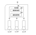
- FIG. 2 is a diagram showing an example of the three-dimensional camera 40.
- the three-dimensional camera 40 has two internal cameras 41 and 42, a projector 43, and a control unit 44.
- the control unit 44 includes an image pickup control unit 441 and an image processing unit 442.
- the internal cameras 41 and 42 and the projector 43 each have a lens.
- the internal cameras 41 and 42 project a pattern projected by the projector 43 on the work 50, which is an object, based on a control instruction from the image pickup control unit 441 described later, and are perpendicular to the optical axes of the internal cameras 41 and 42, respectively.
- a two-dimensional image projected on a flat surface is captured.
- the internal cameras 41 and 42 output the captured two-dimensional image to the image pickup control unit 441.
- the projector 43 irradiates the work 50, which is an object, with a predetermined pattern light with a preset amount of light based on a control instruction from the image pickup control unit 441 described later.
- the three-dimensional camera 40 may be a stereo camera or the like, as will be described later. Further, the three-dimensional camera 40 may be fixedly installed on a pedestal or the like, or may be mounted on the arm of the robot 30.
- the control unit 44 has a CPU (Central Processing Unit), a ROM (Read Only Memory), a RAM (Random Access Memory), a CMOS (Complementary Metal-Oxide-Semiconductor) memory, and the like, and these communicate with each other via a bus. Possiblely configured and known to those of skill in the art.
- the CPU is a processor that controls the three-dimensional camera 40 as a whole.
- the CPU reads out the system program and the application program stored in the ROM via the bus, and controls the entire three-dimensional camera 40 according to the system program and the application program.
- the control unit 44 controls the system program and the application program. It is configured to realize the functions of the image pickup control unit 441 and the image processing unit 442.
- the RAM stores temporary calculation data, two-dimensional images captured by the internal cameras 41 and 42, and various data such as imaging conditions set by the information processing apparatus 10 described later.
- the CMOS memory is backed up by a battery (not shown), and is configured as a non-volatile memory whose storage state is maintained even when the power of the three-dimensional camera 40 is turned off.
- the image pickup control unit 441 controls the image pickup operation of the internal cameras 41 and 42, for example, based on the image pickup conditions set by the information processing apparatus 10 described later. Further, the image pickup control unit 441 controls the amount of light of the projector 43 based on the image pickup conditions set by the information processing apparatus 10.
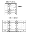
- the image processing unit 442 measures the distance to the work 50, which is an object, and generates a distance image by performing stereo measurement using, for example, two two-dimensional images obtained from the internal cameras 41 and 42, respectively. do. Specifically, the image processing unit 442 uses a distance measurement algorithm known to those skilled in the art (for example, block matching, etc.) to obtain a distance image from two two-dimensional images captured by the internal cameras 41 and 42, respectively. To generate. 3 and 4 are diagrams showing an example of explaining the distance image generation process of the image processing unit 442. As shown in FIG.
- the image processing unit 442 centers on, for example, a pixel of interest whose distance is to be measured, among the two-dimensional images of the work 50 (hereinafter, also referred to as “image IM1”) captured by the internal camera 41.
- image IM1 An image range of 5 pixels ⁇ 5 pixels (hereinafter, also referred to as “small area A”) is extracted.
- the image processing unit 442 searches the image IM2 for a region in which the same pattern as the small region A of the image IM1 is reflected from the two-dimensional image of the work 50 (hereinafter, also referred to as “image IM2”) captured by the internal camera 42. Search from the area.
- the search area is, for example, a region having a width of 5 pixels centered on the same X coordinate as the pixel of interest of the image IM1. Further, the size of the small area A of the image IM1 (5 pixels ⁇ 5 pixels) is the size of the block matching.
- the image processing unit 442 sets the shading value (pixel value) of each pixel in the small area A of the image IM1 and the shading of each pixel every 5 pixels ⁇ 5 pixels while shifting one pixel in the Y-axis direction in the search area of the image IM2.
- the absolute value of the difference from the value (pixel value) is calculated as a block matching score (SAD (Sum of Absolute Image) method).
- SAD Sud of Absolute Image
- the image processing unit 442 When having a value (pixel value), the image processing unit 442 receives
- "16" block matching score is calculated. Further, the image processing unit 442 has
- Calculate the block matching score of "34".
- the shading value (pixel value) is, for example, a value in the range of 0 to 255.
- the image processing unit 442 uses the small area B of FIG. 3, for example, the area shown by a thick solid line, which is the smallest of the block matching scores (matching degree) calculated in the search area of the image IM2, as the small area A of the image IM1. The region having the highest degree of coincidence may be determined.
- the position of A and the position of the small area B of the image IM2 are different.
- the position (X, Y) of the pixel of interest in the small area A of the image IM1 is (200,150)
- the position (X, Y) of the central pixel of the small area B of the image IM2 is (200,300).
- the work 50 is placed on a workbench 60, for example.
- the work 50 may be any as long as it can be gripped or processed by the end effector 31 mounted on the arm of the robot 30, and its shape and the like are not particularly limited.
- FIG. 5 is a functional block diagram showing a functional configuration example of the information processing device 10 as the image pickup condition adjusting device according to the embodiment.
- the information processing device 10 is a computer known to those skilled in the art and operates as an image pickup condition adjusting device.
- the information processing apparatus 10 includes a control unit 11, an input unit 12, a display unit 13, and a storage unit 14. Further, the control unit 11 includes an acquisition unit 110, a reading unit 111, an image pickup condition generation unit 112, a calculation processing unit 113, and an image pickup condition optimization unit 114.
- the input unit 12 is, for example, a keyboard, a touch panel arranged on the display unit 13 described later, or the like, and receives input from an operator. Specifically, the operator inputs, for example, an instruction for adjusting the imaging conditions of the three-dimensional camera 40 via the input unit 12.
- the display unit 13 is, for example, a liquid crystal display or the like, and displays a distance image of the three-dimensional camera 40 acquired by the acquisition unit 110, a CAD model showing the shape of the work 50 read by the reading unit 111 described later, and the like.
- the storage unit 14 is a ROM, an HDD (Hard Disk Drive), or the like, and may store image pickup condition data 141 together with various control programs.
- the image pickup condition data 141 is an image pickup condition applicable to the internal cameras 41 and 42 of the three-dimensional camera 40, and may store a plurality of image pickup conditions generated in advance by the image pickup condition generation unit 112 described later.
- Each of the plurality of imaging conditions stored in the imaging condition data 141 includes at least one such as an exposure time, a light amount of the projector 43 as a light source, a block matching size, and a threshold value of a block matching score.
- the amount of light of the projector 43 is less affected by the ambient light as the amount of light increases, but the portion exposed to the strong light beam tends to cause halation that becomes white and blurred.
- the block matching score is set to a small value, a distance image consisting of three-dimensional points in a small area having a high degree of matching can be obtained. However, if the block matching score is made too small, the number of small regions satisfying the degree of matching decreases, so that there is a possibility that three-dimensional points will be insufficient. If the size of the small area is set as small as, for example, 5 pixels ⁇ 5 pixels, it becomes easier to capture a small change in the shape of the work 50, which is an object, but three-dimensional points such as noise are generated in the distance image.
- the control unit 11 includes a CPU, ROM, RAM, CMOS memory, and the like, which are known to those skilled in the art, which are configured to be communicable with each other via a bus.
- the CPU is a processor that controls the information processing device 10 as a whole.
- the CPU reads out the system program and the application program stored in the ROM via the bus, and controls the entire information processing apparatus 10 according to the system program and the application program.
- the control unit 11 is configured to realize the functions of the acquisition unit 110, the reading unit 111, the image pickup condition generation unit 112, the calculation processing unit 113, and the image pickup condition optimization unit 114. To.
- the acquisition unit 110 acquires a distance image including the work 50 as an object arranged in the field of view of the 3D camera 40 from the 3D camera 40.
- the reading unit 111 reads data of a CAD model showing the shape of the work 50 from an external device (not shown) such as a CAD / CAM device.
- the imaging condition generation unit 112 generates a plurality of imaging conditions, and stores the generated plurality of imaging conditions in the imaging condition data 141.
- the image pickup condition generation unit 112 for example, based on standard image pickup conditions, such as the exposure time included in the image pickup conditions, the light intensity of the projector 43, the block matching size, the threshold value of the block matching score, and the like.
- a plurality of imaging conditions may be generated by changing at least one parameter within a range of preset numerical values.
- the imaging condition generation unit 112 may store the generated plurality of imaging conditions in the imaging condition data 141.
- the calculation processing unit 113 matches the distance image captured by the three-dimensional camera 40 with the CAD model based on a plurality of imaging conditions stored in the imaging condition data 141, and the captured distance image and CAD are matched. Calculate the degree of agreement with the model. Specifically, for example, the calculation processing unit 113 selects a standard imaging condition from a plurality of imaging conditions, and first obtains a distance image imaged (generated) by the three-dimensional camera 40 based on the selected imaging conditions. Acquired via the acquisition unit 110. The calculation processing unit 113 matches the acquired distance image with the CAD model read by the reading unit 111, and a predetermined distance between each three-dimensional point of the distance image and the position of the corresponding CAD model is preset.
- the calculation processing unit 113 It is determined whether or not the distance is equal to or greater than a value (for example, 1 mm or the like).
- the calculation processing unit 113 accumulates three-dimensional points separated by a predetermined value or more as error points, or accumulates the separated lengths, so that the degree of matching between the distance image and the CAD model is used as the CAD model matching score. calculate.
- the calculation processing unit 113 selects an image pickup condition in which parameters such as reducing the size of the block matching are changed, and is imaged (generated) by the three-dimensional camera 40 based on the selected image pickup condition.
- a distance image may be acquired.
- the calculation processing unit 113 matches the acquired distance image with the CAD model, and calculates the degree of matching (CAD model matching score).
- the calculation processing unit 113 selects the next imaging condition based on the determination by the imaging condition optimization unit 114, which will be described later, whether or not the matching degree under the current imaging condition is higher than the matching degree under the previous imaging condition. You may do so.
- the calculation processing unit 113 when the degree of matching under the current imaging condition is higher than the degree of matching under the previous imaging condition, the calculation processing unit 113 further reduces the size of the block matching because the imaging condition is improved. You may select an imaging condition in which the parameters are changed in the same direction of the above, and acquire a distance image imaged (generated) by the three-dimensional camera 40 based on the selected imaging condition. Then, the calculation processing unit 113 may perform matching between the acquired distance image and the CAD model and calculate the degree of matching (the score of CAD model matching). On the other hand, when the degree of matching under the current imaging conditions is lower than the degree of matching under the previous imaging conditions, the calculation processing unit 113 means that the imaging conditions are worse, for example, increasing the size of the block matching.
- FIG. 6 is a diagram showing an example of the shape of the work 50.
- FIG. 7 is a diagram showing an example of a distance image, a CAD model, and matching in a triangular portion of the shape of the work 50 of FIG.
- the ridgeline portion such as the triangular portion of the region C of the ZX plane shown by the broken line, that is, the portion where the shape change is large, is different from the CAD model shown by the solid line as shown in FIG.
- the degree of matching of CAD model matching becomes low.
- an imaging condition in which the size of the block matching is set small is selected, and the imaging condition is based on the selected imaging condition.
- the work 50 may be imaged by the three-dimensional camera 40.
- the three-dimensional camera 40 can capture (generate) a distance image that sensitively captures the delicate features such as the triangular portion in the work 50 of FIG. 6, and the calculation processing unit 113 has a higher match.
- the degree can be calculated.
- the 3D camera 40 when the work 50 has a shape such as a curved surface portion, it is difficult for the 3D camera 40 to accurately image the curved surface portion in a distance, so the block matching score is strictly set.
- the imaging conditions may be selected. By doing so, in the distance image captured (generated) by the 3D camera 40, the information on the curved surface portion is intentionally reduced, the other plane portion becomes dominant, and the degree of agreement with the CAD model is increased. Can be done.
- the imaging conditions may be selected, for example, from among a plurality of imaging conditions stored in the imaging condition data 141, according to the input via the input unit 12 by the operator.
- the image pickup condition optimization unit 114 sets the image pickup condition in the three-dimensional camera 40 such that the degree of matching calculated by the calculation processing unit 113 is equal to or higher than a preset predetermined value. Specifically, in the imaging condition optimizing unit 114, for example, when the matching degree under each imaging condition is sequentially calculated by the calculation processing unit 113, the calculated matching degree is equal to or higher than the set predetermined value.
- the image pickup condition at the present time may be set in the three-dimensional camera 40 as the optimum image pickup condition. It is preferable that the predetermined value is appropriately determined according to the required accuracy of the distance image and the like.
- FIG. 9 is a flowchart illustrating an example of the image pickup condition adjusting process of the information processing apparatus 10.
- step S11 the information processing device 10 causes the robot 30 to operate with respect to the robot control device 20, so that the work 50, which is an object, is arranged on the workbench 60 within the field of view of the three-dimensional camera 40.
- step S12 the reading unit 111 reads a CAD model showing the shape of the work 50 from an external device (not shown) such as a CAD / CAM device.
- step S13 the imaging condition generation unit 112 generates a plurality of imaging conditions and stores the generated plurality of imaging conditions in the imaging condition data 141.
- step S14 the calculation processing unit 113 reads the distance image captured (generated) by the three-dimensional camera 40 based on the imaging conditions selected from the plurality of imaging conditions stored in the imaging condition data 141, and the distance image in step S12. Matching with the CAD model is performed, and the degree of matching between the distance image and the CAD model (CAD model matching score) is calculated.
- step S15 the imaging condition optimization unit 114 determines whether or not the degree of matching calculated in step S14 is equal to or greater than a predetermined value. If the degree of coincidence is equal to or greater than a predetermined value, the process proceeds to step S16. On the other hand, when the degree of matching is smaller than a predetermined value, the process returns to step S14 in order to calculate the degree of matching under the next imaging condition (CAD model matching score).
- step S16 the imaging condition optimizing unit 114 sets the imaging conditions for the three-dimensional camera 40 to have a degree of coincidence of a predetermined value or more.
- the information processing apparatus 10 of one embodiment matches the distance image generated by the three-dimensional camera 40 based on the imaging conditions selected from the generated imaging conditions with the read CAD model. , The degree of matching between the distance image and the CAD model (CAD model matching score) is calculated. When the calculated degree of matching becomes equal to or higher than a predetermined value, the information processing apparatus 10 sets the imaging conditions at that time in the three-dimensional camera 40. As a result, the information processing apparatus 10 can automatically determine the optimum imaging conditions regardless of the skill of the operator, and can reduce the burden of the operator setting the imaging conditions.
- the information processing apparatus 10 is not limited to the above-described embodiment, and includes deformation, improvement, and the like within a range in which the object can be achieved.
- the information processing device 10 is a device different from the robot control device 20, but is not limited thereto.
- the information processing device 10 may be included in the robot control device 20.
- the image pickup condition optimization unit 114 sets the image pickup condition at the time when the degree of coincidence becomes a predetermined value or more in the three-dimensional camera 40, but the present invention is not limited to this.
- the calculation processing unit 113 may calculate the degree of coincidence between the distance image and the CAD model under all the plurality of imaging conditions generated by the imaging condition generation unit 112 and stored in the imaging condition data 141. Then, the imaging condition optimization unit 114 may determine the imaging condition having the highest degree of matching among all the calculated matching degrees. By doing so, the information processing apparatus 10 can set more optimum imaging conditions in the three-dimensional camera 40.
- ⁇ Modification 3> a configuration in which a plurality of imaging conditions are created and imaging is performed based on an imaging condition selected at any time from among them is exemplified, but the present invention is not limited thereto.
- the next imaging condition may be generated based on the comparison between the matching degree under the current imaging condition and the matching degree under the previous imaging condition. Specifically, if the degree of agreement is good, the imaging conditions are corrected in the same direction as the previous time, and if the degree of agreement is poor, the imaging conditions are corrected in the opposite direction to the previous time. You may.
- the distance image may be processed and compared before the comparison of the degree of coincidence between the distance image and the CAD model.
- the calculation of the degree of matching may be speeded up by cutting out or reducing a part of the distance image.
- the distance image may be filtered and subjected to processing such as blurring.
- each function included in the information processing apparatus 10 in one embodiment can be realized by hardware, software, or a combination thereof.
- what is realized by software means that it is realized by a computer reading and executing a program.
- Non-transitory computer-readable media include various types of tangible recording media (Tangible studio media). Examples of non-temporary computer-readable media include magnetic recording media (eg, flexible disks, magnetic tapes, hard disk drives), magneto-optical recording media (eg, magneto-optical disks), CD-ROMs (Read Only Memory), CD-. R, CD-R / W, semiconductor memory (for example, mask ROM, PROM (Programmable ROM), EPROM (Erasable PROM), flash ROM, RAM) are included.
- the program may also be supplied to the computer by various types of temporary computer-readable media (Transition computer readable medium).
- temporary computer readable media include electrical, optical, and electromagnetic waves.
- the temporary computer-readable medium can supply the program to the computer via a wired communication path such as an electric wire and an optical fiber, or a wireless communication path.
- the step of describing the program to be recorded on the recording medium is not only the processing performed in chronological order but also the processing executed in parallel or individually even if it is not necessarily processed in chronological order. Also includes.
- the imaging condition adjusting device and the imaging condition adjusting method of the present disclosure can take various embodiments having the following configurations.
- the imaging condition adjusting device (information processing apparatus 10) of the present disclosure is an imaging condition adjusting device that adjusts the imaging conditions for capturing a distance image of the work 50, and is arranged in the field of view of the three-dimensional camera 40.
- the acquisition unit 110 that acquires a distance image including the work 50 from the 3D camera 40, the reading unit 111 that reads the CAD model of the work 50, and the 3D camera 40 each imaged based on a plurality of generated imaging conditions.
- the calculation processing unit 113 that matches the distance image and the CAD model and calculates the degree of matching between the captured distance image and the CAD model, and the matching degree calculated by the calculation processing unit 113 are equal to or higher than a preset predetermined value.
- It is provided with an imaging condition optimizing unit 114 that sets the imaging conditions to be in the three-dimensional camera 40. According to this image pickup condition adjusting device, the optimum image pickup condition can be automatically determined regardless of the skill of the operator.
- the imaging condition optimization unit 114 determines the imaging condition having the highest matching degree among the matching degrees of each of the plurality of imaging conditions calculated by the calculation processing unit 113. You may. By doing so, the image pickup condition adjusting device can set more optimum image pickup conditions in the three-dimensional camera 40.
- the image pickup condition may include at least one of an exposure time, a light amount of the projector 43, a block matching size, and a threshold value of a block matching score. .. By doing so, the imaging condition adjusting device can acquire a more optimum distance image.
- the imaging condition adjusting method of the present disclosure is an imaging condition adjusting method for adjusting the imaging conditions for capturing a distance image of the work 50, which is realized by a computer and is arranged in the field of view of the three-dimensional camera 40.
- a distance image captured by the 3D camera 40 based on an acquisition process of acquiring a distance image including the work 50 from the 3D camera 40, a reading process of reading a CAD model of the work 50, and a plurality of generated imaging conditions.
- the 3D camera has a calculation process that matches the CAD model with the CAD model and calculates the degree of matching between the captured distance image and the CAD model, and the imaging conditions that make the calculated degree of matching equal to or greater than a preset predetermined value.
- the image pickup condition optimization step set to 40 is provided. According to this imaging condition adjusting method, the same effect as in (1) can be obtained.
- Robot system 10 Information processing device 11 Control unit 110 Acquisition unit 111 Reading unit 112 Imaging condition generation unit 113 Calculation processing unit 114 Imaging condition optimization unit 12 Input unit 13 Display unit 14 Storage unit 141 Imaging condition data 20 Robot control device 30 Robot 40 3D camera
Landscapes
- Engineering & Computer Science (AREA)
- Theoretical Computer Science (AREA)
- Physics & Mathematics (AREA)
- Multimedia (AREA)
- Evolutionary Computation (AREA)
- General Physics & Mathematics (AREA)
- Computer Vision & Pattern Recognition (AREA)
- Computing Systems (AREA)
- Signal Processing (AREA)
- Artificial Intelligence (AREA)
- Health & Medical Sciences (AREA)
- General Engineering & Computer Science (AREA)
- Databases & Information Systems (AREA)
- General Health & Medical Sciences (AREA)
- Medical Informatics (AREA)
- Software Systems (AREA)
- Geometry (AREA)
- Computer Hardware Design (AREA)
- Length Measuring Devices By Optical Means (AREA)
- Studio Devices (AREA)
- Image Analysis (AREA)
- Image Processing (AREA)
Abstract
Description
撮像条件としては、露光時間、光源の光量、ブロックマッチングのサイズ、ブロックマッチングのスコアの閾値等があり、最適な設定を行うには作業者に高いスキルが求められる。このため、作業者にとって撮像条件の設定は大きな負担となっている。
<一実施形態>
図1は、一実施形態に係るロボットシステム1の構成の一例を示す図である。
図1に示すように、ロボットシステム1は、撮像条件調整装置としての情報処理装置10、ロボット制御装置20、ロボット30、3次元カメラ40、ワーク50、及び作業台60を有する。
情報処理装置10、ロボット制御装置20、ロボット30、及び3次元カメラ40は、図示しない接続インタフェースを介して互いに直接接続されてもよい。なお、情報処理装置10、ロボット制御装置20、ロボット30、及び3次元カメラ40は、LAN(Local Area Network)やインターネット等の図示しないネットワークを介して相互に接続されていてもよい。この場合、情報処理装置10、ロボット制御装置20、ロボット30、及び3次元カメラ40は、かかる接続によって相互に通信を行うための図示しない通信部を備えている。また、説明しやすくするために、図1は情報処理装置10とロボット制御装置20をそれぞれ独立に描いていて、この場合の情報処理装置10は例えば撮像条件調整装置として動作するコンピュータより構成されてもよい。このような構成に限定されず、例えば、情報処理装置10はロボット制御装置20の内部に実装され、ロボット制御装置20と一体化されてもよい。
ロボット制御装置20は、ロボット30の動作を制御するための当業者にとって公知の装置である。ロボット制御装置20は、例えば、後述する情報処理装置10によって設定された撮像条件で後述する3次元カメラ40により撮像されたワーク50の距離画像を、情報処理装置10から受信する。ロボット制御装置20は、情報処理装置10から受信した距離画像と公知の手法とに基づいて、対象物であるワーク50の位置及び形状を特定する。ロボット制御装置20は、特定したワーク50の位置及び形状からワーク50を把持したり加工したりするようにロボット30の動作を制御するための制御信号を生成する。そして、ロボット制御装置20は、生成した制御信号をロボット30に対して出力する。
なお、ロボット制御装置20は、後述するように、情報処理装置10を含んでもよい。
ロボット30は、ロボット制御装置20の制御に基づいて動作するロボットである。ロボット30は、鉛直方向の軸を中心に回転するためのベース部、移動及び回転するアーム、及びアームに装着される、例えば溶接ガン、握持ハンド、レーザ照射装置等のエンドエフェクタ31等を備える。
ロボット30は、ロボット制御装置20が出力する制御信号に応じて、アームやエンドエフェクタ31を駆動して、ワーク50を把持したり加工したりする。
なお、ロボット30の具体的な構成については、当業者によく知られているので、詳細な説明は省略する。
また、情報処理装置10やロボット制御装置20は、予め行われたキャリブレーションにより、ロボット30を制御するための機械座標系と、ワーク50の3次元位置を示すカメラ座標系とを対応付けているものとする。
図2は、3次元カメラ40の一例を示す図である。
図2に示すように、3次元カメラ40は、2つの内部カメラ41、42と、プロジェクタ43と、制御部44と、を有する。また、制御部44は、撮像制御部441、及び画像処理部442を有する。また、内部カメラ41、42とプロジェクタ43とはそれぞれレンズを有する。
内部カメラ41、42は、後述する撮像制御部441からの制御指示に基づいて、対象物であるワーク50にプロジェクタ43により投影されたパターンを、内部カメラ41、42それぞれの光軸に対して垂直な平面に投影した2次元画像を撮像する。内部カメラ41、42は、撮像した2次元画像を撮像制御部441に出力する。
プロジェクタ43は、後述する撮像制御部441からの制御指示に基づいて、予め設定された光量で所定のパターン光を対象物であるワーク50に照射する。
なお、3次元カメラ40は、後述するように、ステレオカメラ等でもよい。
また、3次元カメラ40は、架台等に固定設置されてもよく、ロボット30のアームに搭載されてもよい。
制御部44は、CPU(Central Processing Unit)、ROM(Read Only Memory)、RAM(Random Access Memory)、CMOS(Complementary Metal-Oxide-Semiconductor)メモリ等を有し、これらはバスを介して相互に通信可能に構成される、当業者にとって公知のものである。
CPUは3次元カメラ40を全体的に制御するプロセッサである。CPUは、ROMに格納されたシステムプログラム及びアプリケーションプログラムを、バスを介して読み出し、システムプログラム及びアプリケーションプログラムに従って3次元カメラ40全体を制御することで、図2に示すように、制御部44が、撮像制御部441、及び画像処理部442の機能を実現するように構成される。RAMには一時的な計算データや、内部カメラ41、42により撮像された2次元画像、後述する情報処理装置10により設定された撮像条件等の各種データが格納される。CMOSメモリは図示しないバッテリでバックアップされ、3次元カメラ40の電源がオフされても記憶状態が保持される不揮発性メモリとして構成される。
具体的には、画像処理部442は、当業者にとって公知の距離の計測アルゴリズム(例えば、ブロックマッチング等)を用いて、内部カメラ41、42それぞれで撮像された2枚の2次元画像から距離画像を生成する。
図3及び図4は、画像処理部442の距離画像生成処理を説明する一例を示す図である。
図3に示すように、画像処理部442は、内部カメラ41により撮像されたワーク50の2次元画像(以下、「画像IM1」ともいう)のうち、例えば、距離の測定対象の注目画素を中心とする5画素×5画素の画像範囲(以下、「小領域A」ともいう)を抽出する。画像処理部442は、内部カメラ42により撮像されたワーク50の2次元画像(以下、「画像IM2」ともいう)から、画像IM1の小領域Aと同じパターンが映っている領域を画像IM2の探索領域から探索する。
なお、探索領域は、画像IM1の注目画素と同じX座標を中心とする、例えば5画素幅の領域である。また、画像IM1の小領域Aのサイズ(5画素×5画素)は、ブロックマッチングのサイズである。
例えば、画像IM1の小領域Aの5画素×5画素それぞれが図4の上段に示す濃淡値(画素値)を有し、対応する画像IM2の探索領域の各画素が図4の下段に示す濃淡値(画素値)を有する場合、画像処理部442は、画像IM2の探索領域のうち太い実線で示す領域と画像IM1の小領域Aとの、|5-4|+|3-3|+|4-4|+|7-8|+|2-2|+・・・+|4-3|=「16」のブロックマッチングのスコアを算出する。また、画像処理部442は、太い破線で示す領域と画像IM1の小領域Aとの、|5-3|+|3-4|+|4-8|+|7-2|+|2-8|+・・・+|4-1|=「34」のブロックマッチングのスコアを算出する。なお、濃淡値(画素値)は、例えば、0から255の範囲の値である。
画像処理部442は、画像IM2の探索領域で算出したブロックマッチングのスコア(一致度)のうち最小となる、例えば太い実線で示す領域、すなわち図3の小領域Bを、画像IM1の小領域Aと最も一致度が高い領域を判定するようにしてもよい。
そこで、画像処理部442は、算出した視差に基づいて、画像IM1の小領域Aの注目画素の位置に対応するワーク50上の位置と、3次元カメラ40との間の距離を算出することができる。このことから、画像処理部442は、画像IM1における注目画素の位置を変更しつつ、画像IM1全体に対してブロックマッチングを行うことにより、3次元カメラ40の視野内の3次元点群を距離画像として生成することができる。画像処理部442は、生成した距離画像を、後述する情報処理装置10に出力する。
なお、画像処理部442は、距離画像とともに、内部カメラ41、42により撮像された2次元画像も情報処理装置10に出力してもよい。
図5は、一実施形態に係る撮像条件調整装置としての情報処理装置10の機能的構成例を示す機能ブロック図である。
情報処理装置10は、当業者にとって公知のコンピュータであり、撮像条件調整装置として動作する。情報処理装置10は、図5に示すように、制御部11、入力部12、表示部13、及び記憶部14を有する。また、制御部11は、取得部110、読込部111、撮像条件生成部112、算出処理部113、及び撮像条件最適化部114を有する。
入力部12は、例えば、キーボードや、後述する表示部13に配置されたタッチパネル等であり、作業者からの入力を受け付ける。具体的には、作業者は、例えば、入力部12を介して、3次元カメラ40の撮像条件を調整する指示等を入力する。
表示部13は、例えば、液晶ディスプレイ等であり、取得部110が取得した3次元カメラ40の距離画像、及び後述する読込部111により読み込まれたワーク50の形状を示すCADモデル等を表示する。
記憶部14は、ROMやHDD(Hard Disk Drive)等であり、各種の制御用プログラムとともに、撮像条件データ141を記憶してもよい。
撮像条件データ141は、3次元カメラ40の内部カメラ41、42に適用可能な撮像条件で、後述する撮像条件生成部112により予め生成された複数の撮像条件を格納してもよい。撮像条件データ141に格納される複数の撮像条件それぞれには、露光時間、光源であるプロジェクタ43の光量、ブロックマッチングのサイズ、ブロックマッチングのスコアの閾値等の少なくとも1つを含む。
露光時間は、内部カメラ41、42の露光時間が短い程、明色系の対象物を認識しやすくなり、露光時間が長い程、暗色系の対象物を認識しやすくなる。
プロジェクタ43の光量は、光量が大きくなる程外乱光の影響を受けにくくなるが、強い光線が当たる部分が白くぼやけるハレーションを起こしやすくなる。
ブロックマッチングのスコアは、小さな値に設定すると、一致度が高い小領域の3次元点からなる距離画像が得られる。ただし、ブロックマッチングのスコアは、小さくしすぎると、一致度を満たす小領域の数が減少するため、3次元点が不足する可能性がある。
小領域のサイズは、例えば、5画素×5画素等の小さく設定すると対象物であるワーク50の細かな形状変化をとらえやすくなるが、ノイズのような3次元点が距離画像に発生する。
制御部11は、CPU、ROM、RAM、CMOSメモリ等を有し、これらはバスを介して相互に通信可能に構成される、当業者にとって公知のものである。
CPUは情報処理装置10を全体的に制御するプロセッサである。CPUは、ROMに格納されたシステムプログラム及びアプリケーションプログラムを、バスを介して読み出し、前記システムプログラム及びアプリケーションプログラムに従って情報処理装置10全体を制御する。これにより、図5に示すように、制御部11が、取得部110、読込部111、撮像条件生成部112、算出処理部113、及び撮像条件最適化部114の機能を実現するように構成される。
具体的には、撮像条件生成部112は、例えば、標準的な撮像条件を基準にして、撮像条件に含まれる露光時間、プロジェクタ43の光量、ブロックマッチングのサイズ、ブロックマッチングのスコアの閾値等の少なくとも1つのパラメータを予め設定された数値の幅で変化させることにより、複数の撮像条件を生成するようにしてもよい。撮像条件生成部112は、生成した複数の撮像条件を撮像条件データ141に格納するようにしてもよい。
具体的には、算出処理部113は、例えば、複数の撮像条件から標準的な撮像条件を選択し、選択された撮像条件に基づいて3次元カメラ40により撮像(生成)された距離画像を最初に取得部110を介して取得する。算出処理部113は、取得した距離画像と、読込部111により読み込まれたCADモデルとのマッチングを行い、距離画像の各3次元点と対応するCADモデルの位置との距離が予め設定された所定値(例えば、1mm等)以上離間しているか否かを判定する。算出処理部113は、所定値以上離間した3次元点をエラー点として累積したり、離間した長さを累積したりすることにより、距離画像とCADモデルとの一致度をCADモデルマッチングのスコアとして算出する。
一方、今回の撮像条件での一致度が前回の撮像条件での一致度より低くなった場合、算出処理部113は、撮像条件が悪くなっていることから、例えばブロックマッチングのサイズを大きくする等の異なる方向でパラメータが変更された撮像条件を選択し、選択された撮像条件に基づいて3次元カメラ40により撮像(生成)された距離画像を取得してもよい。そして、算出処理部113は、取得した距離画像とCADモデルとのマッチングを行い、一致度(CADモデルマッチングのスコア)を算出してもよい。
そうすることで、情報処理装置10は、最適な撮像条件を見つけ出すことができる。
図6は、ワーク50の形状の一例を示す図である。図7は、図6のワーク50の形状のうち三角形部分における距離画像とCADモデルとマッチングの一例を示す図である。
図6に示すように、ワーク50の形状のうち破線で示すZX平面の領域Cの三角形部分等の稜線部分、すなわち形状変化が大きい部分では、図7に示すように、実線で示すCADモデルと黒丸で示す3次元点との距離が所定値以上離間することから、CADモデルマッチングの一致度が低くなる。
この場合、図6のワーク50における三角形部分等の細やかな特徴を敏感に捉えるようにするには、例えば、ブロックマッチングのサイズが小さく設定された撮像条件を選択し、選択された撮像条件に基づいて3次元カメラ40にワーク50を撮像させてもよい。そうすることで、3次元カメラ40は、図6のワーク50における三角形部分等の細やかな特徴を敏感に捉えた距離画像を撮像(生成)することができ、算出処理部113は、より高い一致度を算出することができる。
具体的には、撮像条件最適化部114は、例えば、算出処理部113により各撮像条件における一致度が順次に算出される場合に、算出された一致度が設定された所定値以上となった時点の撮像条件を最適な撮像条件として3次元カメラ40に設定するようにしてもよい。
なお、所定値は、要求される距離画像の精度等に応じて適宜決定されることが好ましい。
次に、情報処理装置10の撮像条件調整処理に係る動作の一例について説明する。
図9は、情報処理装置10の撮像条件調整処理の一例について説明するフローチャートである。
これにより、情報処理装置10は、作業者のスキルによらず、最適な撮像条件を自動で決定することができ、作業者による撮像条件の設定作業の負担を軽減することができる。
上述の実施形態では、情報処理装置10は、ロボット制御装置20と異なる装置としたが、これに限定されない。例えば、情報処理装置10は、ロボット制御装置20に含まれてもよい。
また例えば、上述の実施形態では、撮像条件最適化部114は、一致度が所定値以上となった時点の撮像条件を3次元カメラ40に設定したが、これに限定されない。例えば、算出処理部113は、撮像条件生成部112により生成され撮像条件データ141に格納された全ての複数の撮像条件における距離画像とCADモデルとの一致度を算出してもよい。そして、撮像条件最適化部114は、算出された全ての一致度のうち、最も高い一致度の撮像条件を決定するようにしてもよい。
そうすることで、情報処理装置10は、より最適な撮像条件を3次元カメラ40に設定することができる。
また例えば、上述の実施形態では、複数の撮像条件を作成して、その中から随時選択された撮像条件に基づいて撮像する構成を例示したが、これに限定されない。例えば、今回の撮像条件での一致度と前回の撮像条件での一致度との比較に基づいて、次回の撮像条件を生成するようにしてもよい。具体的には、一致度が良くなっている場合は、前回と同じ方向で撮像条件を修正し、一致度が悪くなっている場合は、前回とは逆の方向で撮像条件を修正するようにしてもよい。
また例えば、距離画像とCADモデルとの一致度の比較前に、距離画像を加工して比較を実施してもよい。例えば、距離画像の一部を切り出したり、縮小することで、一致度の計算を高速化してもよい。また、CADモデルとの比較が効果的になるのであれば距離画像にフィルタをかけてぼかす等の加工を施してもよい。
この撮像条件調整装置によれば、作業者のスキルによらず、最適な撮像条件を自動で決定することができる。
そうすることで、撮像条件調整装置は、より最適な撮像条件を3次元カメラ40に設定することができる。
そうすることで、撮像条件調整装置は、より最適な距離画像を取得することができる。
この撮像条件調整方法によれば、(1)と同様の効果を奏することができる。
10 情報処理装置
11 制御部
110 取得部
111 読込部
112 撮像条件生成部
113 算出処理部
114 撮像条件最適化部
12 入力部
13 表示部
14 記憶部
141 撮像条件データ
20 ロボット制御装置
30 ロボット
40 3次元カメラ
Claims (4)
- 対象物の距離画像を撮像する撮像条件を調整する撮像条件調整装置であって、
3次元カメラの視野内に配置された前記対象物を含む距離画像を前記3次元カメラから取得する取得部と、
前記対象物のCADモデルを読み込む読込部と、
生成された複数の撮像条件に基づいてそれぞれ前記3次元カメラにより撮像された距離画像と前記CADモデルとのマッチングを行い、撮像された前記距離画像と前記CADモデルとの一致度を算出する算出処理部と、
前記算出処理部により算出された一致度が予め設定された所定値以上となる撮像条件を前記3次元カメラに設定する撮像条件最適化部と、
を備える撮像条件調整装置。 - 前記撮像条件最適化部は、前記算出処理部により算出された前記複数の撮像条件それぞれの一致度のうち最も高い一致度の撮像条件を決定する、請求項1に記載の撮像条件調整装置。
- 前記撮像条件は、露光時間、光源の光量、ブロックマッチングのサイズ、ブロックマッチングのスコアの閾値の少なくとも1つを含む、請求項1又は請求項2に記載の撮像条件調整装置。
- コンピュータにより実現される、対象物の距離画像を撮像する撮像条件を調整する撮像条件調整方法であって、
3次元カメラの視野内に配置された前記対象物を含む距離画像を前記3次元カメラから取得する取得工程と、
前記対象物のCADモデルを読み込む読込工程と、
生成された複数の撮像条件に基づいてそれぞれ前記3次元カメラにより撮像された距離画像と前記CADモデルとのマッチングを行い、撮像された前記距離画像と前記CADモデルとの一致度を算出する算出処理工程と、
算出された一致度が予め設定された所定値以上となる撮像条件を前記3次元カメラに設定する撮像条件最適化工程と、
を備える撮像条件調整方法。
Priority Applications (4)
| Application Number | Priority Date | Filing Date | Title |
|---|---|---|---|
| DE112021005072.9T DE112021005072T5 (de) | 2020-09-28 | 2021-09-21 | Vorrichtung und Verfahren zur Justierung von Bildgebungsbedingung |
| CN202180064515.6A CN116210026A (zh) | 2020-09-28 | 2021-09-21 | 拍摄条件调整装置以及拍摄条件调整方法 |
| US18/025,042 US20240028781A1 (en) | 2020-09-28 | 2021-09-21 | Imaging condition adjusting device and imaging condition adjusting method |
| JP2022551995A JP7415028B2 (ja) | 2020-09-28 | 2021-09-21 | 撮像条件調整装置、及び撮像条件調整方法 |
Applications Claiming Priority (2)
| Application Number | Priority Date | Filing Date | Title |
|---|---|---|---|
| JP2020162038 | 2020-09-28 | ||
| JP2020-162038 | 2020-09-28 |
Publications (1)
| Publication Number | Publication Date |
|---|---|
| WO2022065302A1 true WO2022065302A1 (ja) | 2022-03-31 |
Family
ID=80845468
Family Applications (1)
| Application Number | Title | Priority Date | Filing Date |
|---|---|---|---|
| PCT/JP2021/034570 Ceased WO2022065302A1 (ja) | 2020-09-28 | 2021-09-21 | 撮像条件調整装置、及び撮像条件調整方法 |
Country Status (5)
| Country | Link |
|---|---|
| US (1) | US20240028781A1 (ja) |
| JP (1) | JP7415028B2 (ja) |
| CN (1) | CN116210026A (ja) |
| DE (1) | DE112021005072T5 (ja) |
| WO (1) | WO2022065302A1 (ja) |
Cited By (1)
| Publication number | Priority date | Publication date | Assignee | Title |
|---|---|---|---|---|
| JP2023162508A (ja) * | 2022-04-27 | 2023-11-09 | キヤノン株式会社 | 情報処理装置、情報処理方法、画像処理装置、画像処理方法、ロボットシステム、物品の製造方法、プログラム、及び記録媒体 |
Families Citing this family (1)
| Publication number | Priority date | Publication date | Assignee | Title |
|---|---|---|---|---|
| US20250104275A1 (en) * | 2023-09-22 | 2025-03-27 | The Boeing Company | System and method for establishing the position of a tool relative to a structure |
Citations (3)
| Publication number | Priority date | Publication date | Assignee | Title |
|---|---|---|---|---|
| JP2019138817A (ja) * | 2018-02-14 | 2019-08-22 | オムロン株式会社 | 3次元測定装置、3次元測定方法及び3次元測定プログラム |
| JP2019138822A (ja) * | 2018-02-14 | 2019-08-22 | オムロン株式会社 | 3次元計測システム及び3次元計測方法 |
| JP2019161553A (ja) * | 2018-03-15 | 2019-09-19 | キヤノン株式会社 | 撮像システム、撮像装置、及びそれらの制御方法、プログラム、記憶媒体 |
Family Cites Families (5)
| Publication number | Priority date | Publication date | Assignee | Title |
|---|---|---|---|---|
| JP6798370B2 (ja) * | 2017-03-13 | 2020-12-09 | 株式会社リコー | 撮影装置 |
| JP6822929B2 (ja) * | 2017-09-19 | 2021-01-27 | 株式会社東芝 | 情報処理装置、画像認識方法および画像認識プログラム |
| JP6959277B2 (ja) * | 2019-02-27 | 2021-11-02 | ファナック株式会社 | 3次元撮影装置および3次元撮影条件調整方法 |
| CN110868543A (zh) * | 2019-11-25 | 2020-03-06 | 三星电子(中国)研发中心 | 一种智能拍照方法、装置和计算机可读存储介质 |
| CN111355889B (zh) * | 2020-03-12 | 2022-02-01 | 维沃移动通信有限公司 | 拍摄方法、装置、电子设备和存储介质 |
-
2021
- 2021-09-21 DE DE112021005072.9T patent/DE112021005072T5/de active Pending
- 2021-09-21 JP JP2022551995A patent/JP7415028B2/ja active Active
- 2021-09-21 CN CN202180064515.6A patent/CN116210026A/zh active Pending
- 2021-09-21 US US18/025,042 patent/US20240028781A1/en active Pending
- 2021-09-21 WO PCT/JP2021/034570 patent/WO2022065302A1/ja not_active Ceased
Patent Citations (3)
| Publication number | Priority date | Publication date | Assignee | Title |
|---|---|---|---|---|
| JP2019138817A (ja) * | 2018-02-14 | 2019-08-22 | オムロン株式会社 | 3次元測定装置、3次元測定方法及び3次元測定プログラム |
| JP2019138822A (ja) * | 2018-02-14 | 2019-08-22 | オムロン株式会社 | 3次元計測システム及び3次元計測方法 |
| JP2019161553A (ja) * | 2018-03-15 | 2019-09-19 | キヤノン株式会社 | 撮像システム、撮像装置、及びそれらの制御方法、プログラム、記憶媒体 |
Cited By (1)
| Publication number | Priority date | Publication date | Assignee | Title |
|---|---|---|---|---|
| JP2023162508A (ja) * | 2022-04-27 | 2023-11-09 | キヤノン株式会社 | 情報処理装置、情報処理方法、画像処理装置、画像処理方法、ロボットシステム、物品の製造方法、プログラム、及び記録媒体 |
Also Published As
| Publication number | Publication date |
|---|---|
| CN116210026A (zh) | 2023-06-02 |
| JP7415028B2 (ja) | 2024-01-16 |
| DE112021005072T5 (de) | 2023-07-20 |
| JPWO2022065302A1 (ja) | 2022-03-31 |
| US20240028781A1 (en) | 2024-01-25 |
Similar Documents
| Publication | Publication Date | Title |
|---|---|---|
| EP3974779A1 (en) | Robot hand-eye calibration method and apparatus, computing device, medium and product | |
| JP5911934B2 (ja) | 輪郭線計測装置およびロボットシステム | |
| US9060117B2 (en) | Points from focus operations using multiple light settings in a machine vision system | |
| JP7337495B2 (ja) | 画像処理装置およびその制御方法、プログラム | |
| WO2012053521A1 (ja) | 光学情報処理装置、光学情報処理方法、光学情報処理システム、光学情報処理プログラム | |
| US11024049B2 (en) | Image measurement apparatus | |
| WO2018230098A1 (ja) | 内視鏡システム、内視鏡システムの作動方法 | |
| WO2022065302A1 (ja) | 撮像条件調整装置、及び撮像条件調整方法 | |
| US20200164520A1 (en) | Image processing device, control method thereof, and program storage medium | |
| JP6095486B2 (ja) | 画像測定装置 | |
| JP6420530B2 (ja) | 情報処理装置、計測システム、制御システム、光量決定方法、プログラム及び記憶媒体 | |
| CN115003452A (zh) | 图像处理装置、机床及图像处理方法 | |
| JP6253847B1 (ja) | レーザ加工装置、レーザ加工方法、及びレーザ加工プログラム | |
| CN116921853A (zh) | 一种基于激光切割的视觉测量标定方法、系统及标定终端 | |
| JP2020034484A (ja) | 画像検査装置 | |
| JP2013063487A (ja) | ロボットシステム | |
| JP2022080992A (ja) | 測定装置、制御装置、制御方法及びプログラム | |
| JP4680558B2 (ja) | 撮影及び3次元形状復元方法、並びに撮影及び3次元形状復元システム | |
| JP6025400B2 (ja) | ワーク位置検出装置、及びワーク位置検出方法 | |
| JP2022152480A (ja) | 3次元計測装置、3次元計測方法、プログラム、システム、及び物品の製造方法 | |
| JP2019124609A (ja) | 3d形状のオートトレース方法及び測定機 | |
| CN112809215B (zh) | 激光加工精度校正方法和激光设备 | |
| TW202209261A (zh) | 用於光學檢測的路徑建立方法及其裝置 | |
| TW202439234A (zh) | 教示資料生成裝置、教示資料生成程式、及教示資料生成方法 | |
| JP3931130B2 (ja) | 測定システム、演算方法および演算プログラム |
Legal Events
| Date | Code | Title | Description |
|---|---|---|---|
| 121 | Ep: the epo has been informed by wipo that ep was designated in this application |
Ref document number: 21872431 Country of ref document: EP Kind code of ref document: A1 |
|
| ENP | Entry into the national phase |
Ref document number: 2022551995 Country of ref document: JP Kind code of ref document: A |
|
| WWE | Wipo information: entry into national phase |
Ref document number: 18025042 Country of ref document: US |
|
| 122 | Ep: pct application non-entry in european phase |
Ref document number: 21872431 Country of ref document: EP Kind code of ref document: A1 |