WO2022065031A1 - アーク検出システム、アーク検出方法、及びプログラム - Google Patents
アーク検出システム、アーク検出方法、及びプログラム Download PDFInfo
- Publication number
- WO2022065031A1 WO2022065031A1 PCT/JP2021/032957 JP2021032957W WO2022065031A1 WO 2022065031 A1 WO2022065031 A1 WO 2022065031A1 JP 2021032957 W JP2021032957 W JP 2021032957W WO 2022065031 A1 WO2022065031 A1 WO 2022065031A1
- Authority
- WO
- WIPO (PCT)
- Prior art keywords
- power supply
- arc
- switch
- supply path
- detection system
- Prior art date
- Legal status (The legal status is an assumption and is not a legal conclusion. Google has not performed a legal analysis and makes no representation as to the accuracy of the status listed.)
- Ceased
Links
Images


Classifications
-
- H—ELECTRICITY
- H01—ELECTRIC ELEMENTS
- H01H—ELECTRIC SWITCHES; RELAYS; SELECTORS; EMERGENCY PROTECTIVE DEVICES
- H01H1/00—Contacts
- H01H1/0015—Means for testing or for inspecting contacts, e.g. wear indicator
-
- G—PHYSICS
- G01—MEASURING; TESTING
- G01R—MEASURING ELECTRIC VARIABLES; MEASURING MAGNETIC VARIABLES
- G01R31/00—Arrangements for testing electric properties; Arrangements for locating electric faults; Arrangements for electrical testing characterised by what is being tested not provided for elsewhere
- G01R31/12—Testing dielectric strength or breakdown voltage ; Testing or monitoring effectiveness or level of insulation, e.g. of a cable or of an apparatus, for example using partial discharge measurements; Electrostatic testing
-
- H—ELECTRICITY
- H02—GENERATION; CONVERSION OR DISTRIBUTION OF ELECTRIC POWER
- H02H—EMERGENCY PROTECTIVE CIRCUIT ARRANGEMENTS
- H02H1/00—Details of emergency protective circuit arrangements
- H02H1/0007—Details of emergency protective circuit arrangements concerning the detecting means
- H02H1/0015—Using arc detectors
-
- H—ELECTRICITY
- H02—GENERATION; CONVERSION OR DISTRIBUTION OF ELECTRIC POWER
- H02H—EMERGENCY PROTECTIVE CIRCUIT ARRANGEMENTS
- H02H3/00—Emergency protective circuit arrangements for automatic disconnection directly responsive to an undesired change from normal electric working condition with or without subsequent reconnection ; integrated protection
- H02H3/08—Emergency protective circuit arrangements for automatic disconnection directly responsive to an undesired change from normal electric working condition with or without subsequent reconnection ; integrated protection responsive to excess current
- H02H3/093—Emergency protective circuit arrangements for automatic disconnection directly responsive to an undesired change from normal electric working condition with or without subsequent reconnection ; integrated protection responsive to excess current with timing means
-
- H—ELECTRICITY
- H02—GENERATION; CONVERSION OR DISTRIBUTION OF ELECTRIC POWER
- H02H—EMERGENCY PROTECTIVE CIRCUIT ARRANGEMENTS
- H02H9/00—Emergency protective circuit arrangements for limiting excess current or voltage without disconnection
- H02H9/005—Emergency protective circuit arrangements for limiting excess current or voltage without disconnection avoiding undesired transient conditions
-
- G—PHYSICS
- G01—MEASURING; TESTING
- G01R—MEASURING ELECTRIC VARIABLES; MEASURING MAGNETIC VARIABLES
- G01R31/00—Arrangements for testing electric properties; Arrangements for locating electric faults; Arrangements for electrical testing characterised by what is being tested not provided for elsewhere
- G01R31/50—Testing of electric apparatus, lines, cables or components for short-circuits, continuity, leakage current or incorrect line connections
- G01R31/58—Testing of lines, cables or conductors
-
- H—ELECTRICITY
- H02—GENERATION; CONVERSION OR DISTRIBUTION OF ELECTRIC POWER
- H02H—EMERGENCY PROTECTIVE CIRCUIT ARRANGEMENTS
- H02H1/00—Details of emergency protective circuit arrangements
- H02H1/04—Arrangements for preventing response to transient abnormal conditions, e.g. to lightning or to short duration over voltage or oscillations; Damping the influence of DC component by short circuits in AC networks
Definitions
- the present invention relates to an arc detection system, an arc detection method, and a program for determining whether or not an arc failure may occur in a power supply path.
- Patent Document 1 discloses an arc detecting means for detecting an arc.
- This arc detecting means includes a voltage detecting means for measuring the voltage value between the input side wiring to the terminal block and the output side wiring from the terminal block, and a current detecting means for measuring the current value of the output side wiring from the terminal block. Means and.
- the arc detection means simultaneously detects fluctuations in the voltage value of the voltage detection means and fluctuations in the current value of the current detection means to distinguish between electrical noise and the like and the arc in the terminal block.
- the present invention provides an arc detection system, an arc detection method, and a program that can easily prevent erroneous detection of the occurrence of an arc failure.
- the arc detection system includes an acquisition unit and a determination unit.
- the acquisition unit acquires the measurement result of the current flowing through the power supply path to which power is supplied from the DC power supply.
- the determination unit determines whether or not an arc failure has occurred based on the component of a specific frequency band in the measurement result of the current acquired by the acquisition unit.
- the determination unit determines that the arc failure has occurred when the specific time at which the component of the specific frequency band is equal to or higher than the threshold value is longer than the arc generation time that can occur when the device is attached to or detached from the feeding path. judge.
- the arc detection method includes an acquisition step and a determination step.
- the acquisition step the measurement result of the current flowing through the power supply path to which power is supplied from the DC power supply is acquired.
- the determination step it is determined whether or not an arc failure has occurred based on the component of a specific frequency band in the measurement result of the current acquired in the acquisition step.
- the arc failure occurs when the specific time at which the component of the specific frequency band becomes equal to or higher than the threshold value is longer than the arc generation time that can occur when the device is attached to or detached from the feeding path. judge.
- the program according to one aspect of the present invention causes one or more processors to execute the above arc detection method.
- FIG. 1 is a schematic diagram showing an overall configuration including an arc detection system according to the first embodiment.
- FIG. 2A is a schematic diagram showing the operation of the suppression circuit at the time of attachment / detachment to / from the feeding path of the device in the arc detection system according to the first embodiment.
- FIG. 2B is a schematic diagram showing the operation of the suppression circuit at the time of attachment / detachment to / from the feeding path of the device in the arc detection system according to the first embodiment.
- FIG. 3A is a schematic diagram showing the operation of the suppression circuit at the time of attachment / detachment to / from the feeding path of the device in the arc detection system according to the first embodiment.
- FIG. 1 is a schematic diagram showing an overall configuration including an arc detection system according to the first embodiment.
- FIG. 2A is a schematic diagram showing the operation of the suppression circuit at the time of attachment / detachment to / from the feeding path of the device in the arc detection system according to the first embodiment.
- FIG. 3B is a schematic diagram showing the operation of the suppression circuit at the time of attachment / detachment to / from the feeding path of the device in the arc detection system according to the first embodiment.
- FIG. 4 is a flowchart showing an operation example of the arc detection system according to the first embodiment.
- FIG. 5 is a schematic diagram showing an overall configuration including the arc detection system according to the second embodiment.
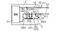
- FIG. 1 is a schematic diagram showing an overall configuration including an arc detection system 100 according to the first embodiment.
- the arc detection system 100 is a system for determining whether or not an arc failure has occurred in the power supply path L1 to which power is mainly supplied from the DC power supply 2. That is, the power supply path L1 may be damaged or broken due to, for example, an external factor or aged deterioration, and an arc (arc discharge) is generated due to such damage, resulting in an arc failure. there's a possibility that. Therefore, the arc detection system 100 is mainly used for detecting an arc failure that may occur in the feeding path L1.
- the arc detection system 100 is used for a so-called DC (Direct Current) distribution network 200.
- the DC distribution network 200 is configured to include one or more power supply paths L1. In FIG. 1, only one power supply path L1 is shown. DC power is supplied to the DC distribution network 200 from the DC power source 2.
- Each power supply path L1 is composed of a pair of electric circuits, that is, a positive power supply path connected to the positive electrode on the output side of the DC power supply 2 and a negative power supply path connected to the negative electrode on the output side of the DC power supply 2. There is.
- DC power is supplied from the DC power supply 2 to this power supply path L1.
- the DC distribution network 200 has a plurality of power supply paths L1, one end of each of the plurality of power supply paths L1 is connected to one or more branch points. Therefore, when DC power is supplied from the DC power source 2 to any of the power supply paths L1, DC power is also supplied to the other power supply paths L1 via one or more branch points.
- the DC power supply 2 is a power converter including an AC / DC converter 21.
- the DC power supply 2 converts the AC power output from the power system 300 into DC power, and outputs the converted DC power to the power supply path L1 to which the DC power supply 2 is connected.
- the DC distribution network 200 has a plurality of power supply paths L1
- the DC power output to the power supply path L1 is also output to the other power supply paths L1.
- the DC power supply 2 may be a mode that outputs DC power, and may be a distributed power source such as a solar cell or a power source such as a storage battery, or these power sources and a power converter (for example, DC / It may be a combination with a power converter provided with a DC converter circuit).
- Each power supply path L1 is composed of, for example, a duct rail, and one or more devices 3 can be attached to it. That is, in each power supply path L1, one or more devices 3 can be arranged at free positions. Of course, each power supply path L1 may have a mode in which a place where one or more devices 3 can be attached is predetermined. In the first embodiment, each power supply path L1 is arranged on the ceiling of the facility, but may be arranged on the floor, wall, furniture, or the like of the facility.
- the device 3 has a load 31 and a pair of connection terminals 32.
- the device 3 can be attached to or removed from the power supply path L1 via the pair of connection terminals 32.
- the device 3 is rotated clockwise when viewed from the insertion direction of the device 3 with the pair of connection terminals 32 of the device 3 inserted into the duct rail (power supply path L1).
- a predetermined angle for example, 90 degrees.
- the pair of connection terminals 32 are fixed in contact with the pair of connection conductors L11 provided in the power supply path L1, and the device 3 is electrically and mechanically connected to the power supply path L1.
- the device 3 When the device 3 is removed from the power supply path L1, the device 3 is rotated by a predetermined angle in the opposite direction to the above when viewed from the insertion direction of the device 3. As a result, the contact state between the pair of connection terminals 32 and the pair of connection conductors L11 is released, so that the device 3 can be subsequently removed from the power supply path L1.
- the load 31 is driven by receiving DC power supplied from the DC power supply 2 via the power supply path L1 in a state where the device 3 is attached to the power supply path L1.
- the device 3 is a lighting fixture, but may be, for example, a speaker, a camera, a sensor, a USB PD (Power Delivery), or the like. That is, the device 3 may be a device other than the lighting fixture as long as the load 31 is driven by receiving electric power. Further, in the first embodiment, all the devices 3 connected to each power supply path L1 are lighting fixtures and have one type, but even if there are a plurality of types of devices 3 connected to each power supply path L1. good. For example, a lighting fixture, a speaker, a camera, a sensor, and a USB PD may be connected to each power supply path L1. All of these devices 3 may be connected to one power supply path L1, or may be divided and connected to a plurality of power supply paths L1.
- the arc detection system 100 includes an acquisition unit 11, a determination unit 12, a notification unit 13, a stop unit 14, a suppression circuit 4, and functional components for determining whether or not an arc failure has occurred. It is equipped with.
- the acquisition unit 11, the determination unit 12, the notification unit 13, and the stop unit 14 are provided in the DC power supply 2, and the suppression circuit 4 is provided in each device 3.
- the arc detection system 100 is, for example, a microcomputer or a device including a microcomputer.
- the microcomputer is a semiconductor integrated circuit having a ROM and RAM in which a program is stored, a processor (CPU: Central Processing Unit) for executing the program, a timer, an A / D converter, a D / A converter, and the like.
- the acquisition unit 11, the determination unit 12, the notification unit 13, and the stop unit 14 are all realized by the processor executing the above program.
- the acquisition unit 11 acquires the measurement result of the current I1 flowing in the power supply path L1 to which the power is supplied from the DC power supply 2.
- the acquisition unit 11 acquires the measurement result of the current I1 measured by sampling at a predetermined cycle (sampling cycle) with the ammeter 22. That is, the acquisition unit 11 acquires the measurement result of the current I1 from the ammeter 22 at a predetermined cycle.
- the ammeter 22 is provided between the DC power supply 2 and the power supply path L1 and measures the current flowing in the negative power supply path of the power supply path L1 (that is, the current I1 flowing in the power supply path L1).
- the ammeter 22 may be built in the DC power supply 2.
- the determination unit 12 determines whether or not an arc failure has occurred based on the component of a specific frequency band in the measurement result of the current I1 acquired by the acquisition unit 11. Specifically, the determination unit 12 frequency-analyzes the measurement result of the current I1 acquired by the acquisition unit 11. The frequency analysis is to calculate the frequency spectrum of the measurement result of the current I1 by, for example, Fourier transforming (here, FFT (FastFourier Transform)) the time waveform of the measurement result of the current I1. Then, the determination unit 12 determines whether or not an arc failure has occurred by referring to the calculated frequency spectrum.
- the specific frequency band is, for example, a band including the frequency of noise generated when an arc failure occurs.
- the specific frequency band is, for example, a tens of kHz band, which is a relatively high frequency band. The frequency of noise generated in the above cases can be obtained experimentally.
- the determination unit 12 compares the specific time at which the component of the specific frequency band is equal to or greater than the threshold value with the preset threshold time (for example, 1 second), and when the specific time is longer than the threshold time, It is determined that an arc failure has occurred.
- the threshold time is preset based on the arc generation time that can occur when the device 3 is attached to or detached from the power supply path L1. That is, the determination unit 12 has encountered an arc failure when the specific time in which the component of the specific frequency band is equal to or greater than the threshold value is longer than the arc generation time that can occur when the device 3 is attached to or detached from the power supply path L1. Is determined.
- the process leading to the determination of the occurrence of the arc failure will be described.
- the arcs that can be generated in the DC distribution network 200 include an arc caused by a disconnection or a half disconnection of the power supply path L1 and an arc that can be instantaneously generated when the device 3 is attached to and detached from the power supply path L1. That is, when the device 3 is attached to the power supply path L1, if the device 3 is not smoothly attached, the load 31 of the device 3 is connected to the power supply path L1 and is disconnected from the power supply path L1. Is repeated in a short period of time, so-called chattering may occur. Then, during the chattering generation period, an arc may occur when the load 31 is momentarily disconnected from the feeding path L1 while the current is flowing.
- chattering may occur in the same manner as described above. Then, during the chattering generation period, an arc may occur when the load 31 is momentarily disconnected from the feeding path L1 while the current is flowing.
- the generation of arcs due to such chattering can occur not only in the DC distribution network 200 but also in the AC distribution network.
- the current flowing in the feeding path is an alternating current, there is a moment when the current becomes zero, so that the duration of the arc caused by chattering tends to be short. Specifically, the duration of the arc is less than half the period of the alternating current.
- the current flowing through the feeding path L1 is a direct current
- the current does not become zero and the duration of the arc due to chattering tends to be long.
- the device 3 is attached to the feeding path L1 while the distance between the electrode of the device 3 and the electrode of the feeding path L1 is halfway, the arc is less likely to disappear.
- the arc caused by the disconnection or half disconnection of the power supply path L1 tends to cause an arc failure, but the arc caused by chattering basically disappears in a short period of time, so that it is unlikely to cause an arc failure. Therefore, in the arc detection system 100, it is desired to determine that the occurrence of an arc mainly due to a disconnection or a half disconnection of the power supply path L1 is the occurrence of an arc failure without detecting a short-time arc due to chattering. ..
- the suppression circuit 4 is provided in each device 3 in order to satisfy the above-mentioned request.
- the suppression circuit 4 is configured so that when the device 3 is attached to the power supply path L1, the load 31 is connected to the power supply path L1 with a delay time.
- the load 31 will be connected to the power supply path L1 after the device 3 will be securely attached to the power supply path L1, and the load 31 will be connected to the power supply path L1 with the above-mentioned current flowing.
- the situation of momentary disconnection is unlikely to occur, and as a result, the arc caused by chattering is less likely to occur.
- the suppression circuit 4 is disconnected from the power supply path L1 of the device 3 before the device 3 is removed from the power supply path L1. It is configured as follows. As a result, the device 3 is removed from the power supply path L1 after the device 3 is disconnected from the power supply path L1, and the load 31 is instantaneously disconnected from the power supply path L1 with the above-mentioned current flowing. Situations are less likely to occur, and as a result, arcs due to chattering are less likely to occur.
- the determination unit 12 is not an arc caused by chattering, but a disconnection or disconnection in the feeding path L1. It is determined that an arc is generated due to a half disconnection, that is, an arc failure has occurred. That is, in the first embodiment, the specific time is longer than the delay time.
- the suppression circuit 4 does not exist, it is considered that an arc due to chattering may occur in a period corresponding to the delay time. Therefore, the fact that the specific time is longer than the delay time corresponds to the specific time being longer than the arc generation time that can occur when the device 3 is attached to or detached from the power supply path L1.
- an arc due to chattering may occur when the device 3 is attached to or detached from the power supply path L1.
- the determination unit 12 does not determine that an arc failure has occurred even if an arc caused by chattering occurs.
- an arc failure may occur due to an arc caused by chattering.
- the determination unit 12 can determine that the arc failure has occurred even in such a case.
- the notification unit 13 notifies the surroundings that an arc failure has occurred, for example, by turning on a lamp or sounding a buzzer. Further, the notification unit 13 notifies that an arc failure has occurred by transmitting information indicating that an arc failure has occurred to an information terminal owned by the owner or administrator of the arc detection system 100. You may.
- the information terminal may include a personal computer or the like as well as a mobile terminal such as a smartphone or a tablet.
- the stop unit 14 stops the current flowing in the power supply path L1 when the determination unit 12 determines that an arc failure has occurred. As a result, if an arc discharge is generated due to an arc failure, the arc discharge disappears.
- the stop unit 14 stops the current flowing in the power supply path L1 by controlling the switch connected to the power supply path L1.
- the switch is, for example, a mechanical switch or a semiconductor switch.
- the mechanical switch is, for example, a switch such as a relay or a breaker
- the semiconductor switch is a switch such as a transistor or a diode.
- the switch connected to the power supply path L1 may be a switch directly connected to the power supply path L1 or a switch indirectly connected to the power supply path L1.
- the switch is a switch for realizing the AC / DC conversion function in the AC / DC converter 21. Even if the switch is not directly connected to the power supply path L1, it is indirectly connected to the power supply path L1, so that the switch is connected to the power supply path L1.
- the stop unit 14 controls the switch to stop the switching operation of the switch, thereby stopping the current flowing in the power supply path L1.
- the switch may be configured to switch the DC power supply 2 on and off.
- the stop unit 14 controls the switch to turn off the DC power supply 2 to stop the current flowing in the power supply path L1.
- the switch may be provided on the power supply path L1, and the switch may be configured to switch the opening and closing of the power supply path L1.
- the stop unit 14 may stop the current flowing in the power supply path L1 by controlling the switch to open the power supply path L1.
- the suppression circuit 4 is a circuit for suppressing an arc that may occur when the device 3 is attached to or detached from the power supply path L1.
- the suppression circuit 4 has a first switch SW1, a second switch SW2, and a drive circuit 41.
- the suppression circuit 4 is provided between the load 31 of the device 3 and the pair of connection terminals 32 in each device 3.
- the first switch SW1 opens and closes the electric circuit L2 between the load 31 of the device 3 and the power supply path L1.
- the electric circuit L2 has an electric circuit connecting the connection terminal 32 on the positive electrode side of the pair of connection terminals 32 and the positive electrode of the load 31, and the connection terminal 32 on the negative electrode side of the pair of connection terminals 32 and the negative electrode of the load 31. It consists of an electric circuit to connect.
- the electric circuit L2 is closed to electrically connect the pair of connection terminals 32 and the load 31. In this state, when the device 3 is attached to the power supply path L1, electric power is supplied from the power supply path L1 to the load 31 (that is, a current flows).
- the electric path L2 is opened to electrically disconnect the pair of connection terminals 32 and the load 31. In this state, even if the device 3 is attached to the power supply path L1, power is not supplied from the power supply path L1 to the load 31 (that is, no current flows).
- the first switch SW1 is an n-channel enhancement type MOSFET (Metal-Oxide-Semiconductor Field-Effect Transistor). That is, the first switch SW1 is a field effect transistor.
- FIG. 1 the symbol of the diode between the drain and the source represents the parasitic diode of the first switch SW1. The same applies to FIG. 5, which will be described later.
- the drain of the first switch SW1 is connected to the negative electrode of the load 31, and the source of the first switch SW1 is connected to the negative connection terminal 32 of the pair of connection terminals 32.
- the gate of the first switch SW1 is connected to the drive circuit 41.
- the drive circuit 41 drives the first switch SW1 so as to close the electric circuit L2 after the lapse of the delay time after the device 3 is connected to the electric circuit L2.
- the drive circuit 41 is connected to the gate of the first switch SW1 and includes a CR filter 42 that applies the charging voltage of the capacitor C1 to the gate of the first switch SW1.
- the delay time is determined by the time constant of the CR filter 42.
- the drive circuit 41 has a first resistance element R1, a second resistance element R2, a capacitor C1, and a Zener diode ZD1.
- the CR filter 42 is composed of the first resistance element R1, the second resistance element R2, and the capacitor C1.
- One end of the first resistance element R1 is connected to the positive connection terminal 32 of the pair of connection terminals 32 and the positive electrode of the load 31, and the other end of the first resistance element R1 is the gate of the first switch SW1. It is connected to the.
- One end of the second resistance element R2 is connected to the gate of the first switch SW1, and the other end of the second resistance element R2 is connected to the negative side of the pair of connection terminals 32 via the second switch SW2. It is connected to the terminal 32.
- One end of the capacitor C1 is connected to the gate of the first switch SW1, and the other end of the capacitor C1 is connected to the source of the first switch SW1.
- the Zener diode ZD1 is connected between the gate and the source of the first switch SW1 and suppresses an excessive voltage from being applied between the gate and the source of the first switch SW1.
- the Zener diode ZD1 is replaced with a resistor whose voltage division ratio with the first resistance element R1 is set so that the gate-source voltage of the first switch SW1 becomes a voltage sufficient to switch to the ON state. May be good. Further, a resistor may be further connected in parallel with the Zener diode ZD1. The same applies to the second embodiment described later.
- the delay time is set so that power is not supplied to the device 3 during the chattering generation period that may occur when the device 3 is attached to and detached from the power supply path L1.
- the second switch SW2 is configured to switch between the gate of the first switch SW1 and the electric circuit L2 from one of the short-circuited state and the open state to the other.
- the second switch SW2 is a normally-off type push button switch and is exposed to the outside of the device 3.
- the second switch SW2 switches to the on state (that is, a short-circuit state) only while the user is performing the push operation, and maintains the off state (that is, the open state) while the user is not performing the push operation.
- One end of the second switch SW2 is connected to the gate of the first switch SW1 via the second resistance element R2, and the other end of the second switch SW2 is the negative connection terminal of the pair of connection terminals 32. It is connected to 32.
- FIGS. 2A to 3B are schematic views showing the operation of the suppression circuit 4 at the time of attachment / detachment to / from the power supply path L1 of the device 3.
- the expression of the first switch SW1 is different from that of FIG. 1 in order to make it easier to visually understand the on / off of the first switch SW1.
- the operation of the suppression circuit 4 when the device 3 is attached to the power supply path L1 will be described.
- the user attaches the device 3 to the power supply path L1 while operating the second switch SW2.
- the first switch SW1 is turned off. It is in a state, and the electric circuit L2 is open.
- the device 3 is electrically connected to the power supply path L1, but since the second switch SW2 is in the ON state, the charging current I11 does not flow through the capacitor C1 and the first switch SW1 does not turn on. ..
- the user inserts the device 3 into the power supply path L1 while operating the second switch SW2, and rotates the device 3 by a predetermined angle to electrically and mechanically connect the device 3 to the power supply path L1. This completes the attachment of the device 3 to the power supply path L1. After that, the user releases the second switch SW2 to turn off the second switch SW2. That is, as long as the user is operating the second switch SW2, in other words, the first switch SW1 is basically not turned on until the user completes the attachment of the device 3 to the power supply path L1.
- the charging current I11 flows through the capacitor C1 via the first resistance element R1 in the CR filter 42 of the drive circuit 41, so that charging of the capacitor C1 is started.
- the capacitor C1 is charged according to a time constant based on the resistance value of the first resistance element R1 and the capacitance value of the capacitor C1.
- the suppression circuit 4 turns on the first switch SW1 after the lapse of the delay time from the time when the device 3 is connected to the electric circuit L2 (here, the time when the second switch SW2 is turned off). Power is supplied from the power supply path L1 to the load 31 after the delay time has elapsed from the time point. Therefore, even if chattering occurs when the device 3 is attached to the power supply path L1, power is not supplied from the power supply path L1 to the load 31 during the chattering generation period, so that it is possible to suppress the generation of an arc due to chattering. can.
- the user may forget to operate the second switch SW2.
- the charging current I11 starts to flow in the capacitor C1 from the time of contact.
- the suppression circuit 4 turns on the first switch SW1 after the delay time has elapsed from the time when the device 3 is connected to the electric circuit L2 (here, the contact time)
- the delay time elapses from the above time.
- power is supplied from the power supply path L1 to the load 31. Therefore, even if chattering occurs in such a case, it becomes difficult to supply electric power from the power supply path L1 to the load 31 during the chattering generation period, so that the effect of suppressing the generation of an arc due to chattering can be expected.
- the operation of the suppression circuit 4 when the device 3 is removed from the power supply path L1 will be described.
- the user removes the device 3 from the power supply path L1 while operating the second switch SW2.
- the second switch SW2 is turned on before the device 3 is removed from the power supply path L1.
- the discharge current I12 flows from the capacitor C1 to the feeding path L1 via the second resistance element R2, so that the discharge of the capacitor C1 is started.
- the capacitor C1 is discharged according to a time constant based on the resistance value of the second resistance element R2 and the capacitance value of the capacitor C1.
- the suppression circuit 4 turns off the first switch SW1 after the lapse of the delay time from the time when the second switch SW2 is turned on, so that the power supply path of the device 3 is before the device 3 is removed from the power supply path L1.
- the electrical connection to L1 is disconnected. Therefore, even if chattering occurs when the device 3 is removed from the power supply path L1, power is not supplied from the power supply path L1 to the load 31 during the chattering generation period, so that it is possible to suppress the generation of an arc due to chattering. can.
- the device 3 may be removed from the power supply path L1 before the delay time elapses.
- an arc may be generated when the device 3 is removed from the feeding path L1, but the arc generation time can be shortened as compared with the case where the suppression circuit 4 does not exist, resulting in chattering. It can be said that the generation of arc is suppressed.
- the resistance value of the second resistance element R2 is preferably smaller than the resistance value of the first resistance element R1. If the resistance value of the second resistance element R2 is small, the delay time until the first switch is turned off becomes short. If this delay time is short, it is less likely that the device 3 is attached to and detached from the power supply path L1 at a time earlier than the delay time, and an arc due to chattering is less likely to occur. However, the shorter the delay time is, the more preferable it is, and if it is made extremely short, conversely, an arc due to the first switch SW1 being turned off in an instant may occur. Therefore, for example, this delay time is preferably about several tens of milliseconds.
- the load 31 may be connected to the feeding path L1 after the device 3 is surely attached to the feeding path L1, so that the first switch SW1 is turned on.
- the delay time may be long. However, if this delay time is made extremely long, the time from when the device 3 is attached to the power supply path L1 until the load 31 is actually driven becomes long, and the user may feel a sense of discomfort. Therefore, for example, this delay time is preferably about several hundred milliseconds.
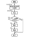
- FIG. 4 is a flowchart showing an operation example of the arc detection system 100 according to the first embodiment.
- the acquisition unit 11 acquires the measurement result of the current I1 from the ammeter 22 at a predetermined cycle (S1).
- the process S1 corresponds to the acquisition step ST1 of the arc detection method.
- the determination unit 12 determines whether or not an arc failure has occurred based on the component of a specific frequency band in the measurement result of the current I1 acquired by the acquisition unit 11 (S2).
- the determination unit 12 determines by frequency analysis of the measurement result of the current I1 acquired by the acquisition unit 11.
- the determination unit 12 compares the component of the specific frequency band with the threshold value, and the specific time when the component of the specific frequency band is equal to or higher than the threshold value and the state continues is the threshold time. If it is longer than, it is determined that an arc failure has occurred (S3: Yes). On the other hand, the determination unit 12 determines that no arc failure has occurred when the specific time has not reached the threshold time or when the component of the specific frequency band is below the threshold value (S3: No).
- the processes S2 and S3 correspond to the determination step ST2 of the arc detection method.
- the stop unit 14 stops the current flowing through the power supply path L1 to supply power from the DC power supply 2 to the power supply path L1. Is stopped (S4). Then, the notification unit 13 notifies the occurrence of an arc failure (S5). On the other hand, when the determination unit 12 determines that no arc failure has occurred (S3: No), the processing of the arc detection system 100 ends. Hereinafter, the above series of processes S1 to S5 are repeated.
- the arc detection system of the comparative example is implemented in that when the component of a specific frequency band in the measurement result of the current I1 acquired by the acquisition unit 11 exceeds the threshold value, it is immediately determined that an arc failure has occurred. It is different from the arc detection system 100 according to the first embodiment.
- the conditions required for the arc detection system will be explained. If an arc is generated due to a break or half break in the feeder line L1, if this state is left unattended, the broken or half broken part will generate excessive heat, and in some cases, it may ignite and lead to a fire. be. Therefore, it is important for the arc detection system to detect the occurrence of an arc (that is, the occurrence of an arc failure) as soon as possible, and to stop the power supply to the power supply path L1 before a situation such as a fire occurs. For example, the UL (Underwriters Laboratories) standard requires that the occurrence of an arc failure be detected within 2 seconds after the occurrence of an arc.
- an event such as notifying the user that an arc failure has occurred may occur, which is troublesome for the user.
- the power supply from the DC power supply 2 to the power supply path L1 is automatically stopped when it is determined that an arc failure has occurred.
- an event may occur in which the power supply to the power supply path L1 is stopped each time the device 3 is attached to or detached from the power supply path L1, which is also troublesome for the user.
- the arc detection system 100 it is determined that an arc failure has occurred when an arc due to a disconnection or a half disconnection of the feeding path L1 has occurred, and when an arc due to chattering has occurred. Basically does not determine that an arc failure has occurred. That is, in the arc detection system 100 according to the first embodiment, it is unlikely that the arc failure is determined to have occurred due to the generation of an arc that is unlikely to cause the arc failure. In other words, the arc detection system 100 according to the first embodiment does not detect an event that does not lead to an arc failure even if it occurs temporarily, such as an arc that may occur when the device 3 is attached to or detached from the power supply path L1.
- FIG. 5 is a schematic diagram showing an overall configuration including the arc detection system 100 according to the second embodiment.
- the DC power supply 2 is not shown. Therefore, in FIG. 5, the acquisition unit 11, the determination unit 12, the notification unit 13, and the stop unit 14, which are the components of the arc detection system 100, are not shown.
- the configuration of the suppression circuit 4A is different from the configuration of the suppression circuit 4 in the arc detection system 100 according to the first embodiment.
- the differences from the first embodiment will be mainly described, and the common points with the first embodiment will be omitted as appropriate.
- the suppression circuit 4A has a first switch SW1, a second switch SW2, and a drive circuit 41, similarly to the suppression circuit 4 of the first embodiment.
- the arrangement of the components of the first switch SW1, the second switch SW2, and the drive circuit 41 is different from that of the suppression circuit 4 of the first embodiment.
- the drive circuit 41 of the second embodiment further has a power supply circuit 43, unlike the suppression circuit 4 of the first embodiment.
- the first switch SW1 is an n-channel enhancement type MOSFET as in the first embodiment.
- the drain of the first switch SW1 is connected to the positive connection terminal 32 of the pair of connection terminals 32, and the source of the first switch SW1 is connected to the positive electrode of the load 31.
- the gate of the first switch SW1 is connected to the drive circuit 41.
- the second switch SW2 is a normally-off type push button switch as in the first embodiment. One end of the second switch SW2 is connected to the gate of the first switch SW1 via the second resistance element R2, and the other end of the second switch SW2 is the positive connection terminal of the pair of connection terminals 32. It is connected to 32.
- the drive circuit 41 includes a first resistance element R1, a second resistance element R2, a capacitor C1, a Zener diode ZD1, and a power supply circuit 43.
- the CR filter 42 is composed of the first resistance element R1, the second resistance element R2, and the capacitor C1.
- One end of the first resistance element R1 is connected to the gate of the first switch SW1, and the other end of the first resistance element R1 is connected to the high voltage side output terminal 432 of the pair of output terminals 432 of the power supply circuit 43. It is connected.
- One end of the second resistance element R2 is connected to the gate of the first switch SW1, and the other end of the second resistance element R2 is connected to the positive side of the pair of connection terminals 32 via the second switch SW2. It is connected to the terminal 32.
- One end of the capacitor C1 is connected to the gate of the first switch SW1, and the other end of the capacitor C1 is connected to the source of the first switch SW1.
- the Zener diode ZD1 is connected between the gate and the source of the first switch SW1 and suppresses an excessive voltage from being applied between the gate and the source of the first switch SW1.
- the power supply circuit 43 has a pair of input terminals 431 and a pair of output terminals 432, and the pair of input terminals 431 and the pair of output terminals 432 are electrically isolated from each other. Further, the power supply circuit 43 generates a drive voltage for driving the gate of the first switch SW1 based on the voltage applied to the pair of input terminals 431, and outputs the generated drive voltage from the pair of output terminals 432. do.
- the pair of input terminals 431 are each connected to the pair of connection terminals 32.
- the high-voltage side output terminal 432 of the pair of output terminals 432 is connected to the gate of the first switch SW1 via the first resistance element R1, and the low-voltage side output terminal 432 is connected to the positive electrode of the load 31. Has been done.
- the time constant and the delay time are determined based on the resistance value of the first resistance element R1 and the capacitance value of the capacitor C1.
- the time constant and the delay time are determined based on the resistance value of the second resistance element R2 and the capacitance value of the capacitor C1.
- the operation of the suppression circuit 4A will be described.
- the operation of the suppression circuit 4A when the device 3 is attached to the power supply path L1 will be described.
- the user attaches the device 3 to the power supply path L1 while operating the second switch SW2.
- the first switch SW1 is in the off state and the electric circuit L2 is in the off state. It is open.
- the device 3 is electrically connected to the power supply path L1, but since the second switch SW2 is in the ON state, the charging current does not flow through the capacitor C1 and the first switch SW1 does not turn on.
- the user inserts the device 3 into the power supply path L1 while operating the second switch SW2, and rotates the device 3 by a predetermined angle to electrically and mechanically connect the device 3 to the power supply path L1. This completes the attachment of the device 3 to the power supply path L1. After that, the user releases the second switch SW2 to turn off the second switch SW2. That is, as long as the user is operating the second switch SW2, in other words, the first switch SW1 is basically not turned on until the user completes the attachment of the device 3 to the power supply path L1.
- the capacitor C1 is sufficiently charged and the charging voltage of the capacitor C1 (that is, the gate-source voltage of the first switch SW1) reaches a predetermined voltage, the first switch SW1 is turned on and the electric circuit L2 is turned on. Closed. As a result, electric power is supplied from the power supply path L1 to the load 31.
- the operation of the suppression circuit 4A when the device 3 is removed from the power supply path L1 will be described.
- the user removes the device 3 from the power supply path L1 while operating the second switch SW2.
- the second switch SW2 is turned on before the device 3 is removed from the power supply path L1.
- the discharge current flows from the capacitor C1 to the feeding path L1 via the second resistance element R2, so that the discharge of the capacitor C1 is started.
- the capacitor C1 is discharged according to a time constant based on the resistance value of the second resistance element R2 and the capacitance value of the capacitor C1.
- the charging voltage of the capacitor C1 that is, the gate-source voltage of the first switch SW1
- the first switch SW1 is turned off and the electric circuit L2 is turned off. Be released.
- electric power is not supplied from the power supply path L1 to the load 31.
- the pair of connection terminals 32 of the device 3 and the pair of connection conductors L11 of the power supply path L1 are separated from each other, so that the device 3 is electrically connected to the power supply path L1. The connection is disconnected.
- the suppression circuit 4A operates in the same manner as the suppression circuit 4 of the first embodiment. Further, the arc detection system 100 according to the second embodiment has the same configuration as the arc detection system 100 according to the first embodiment, except for the suppression circuit 4A. Therefore, the arc detection system 100 according to the second embodiment can have the same effect as the arc detection system 100 according to the first embodiment.
- the ammeter 22 is a device different from the arc detection system 100, but may be built in the arc detection system 100.
- the arc detection system 100 is provided in the DC power supply 2, but the present invention is not limited to this.
- the arc detection system 100 may be connected to the power supply path L1 as a device separate from the DC power supply 2.
- the arc detection system 100 if the arc detection system 100 is configured to be able to communicate with the DC power supply 2 by wire communication or wireless communication, the arc detection system 100 gives an instruction to the DC power supply 2 according to the determination result of the determination unit 12. Is possible.
- the determination unit 12 extracts the component of a specific frequency band by performing frequency analysis on the measurement result of the current I1 acquired by the acquisition unit 11.
- the determination unit 12 extracts the frequency component of a specific frequency band by passing the measurement result of the current I1 acquired by the acquisition unit 11 through a filter (for example, a bandpass filter) instead of executing the frequency analysis. You may.
- the second switch SW2 is configured to be turned on / off by being operated by the user's hand, but the present invention is not limited to this.
- the second switch SW2 may be configured to automatically switch on / off according to the attachment / detachment of the device 3 to / from the power supply path L1.
- the second switch SW2 may be configured to temporarily switch to a short-circuited state at least when the device 3 is removed from the power supply path L1.
- the second switch SW2 is a normally-on type push button switch, and is configured to switch to an off state (open state) when a predetermined force is applied. That is, the second switch SW2 maintains an on state (short-circuited state) when the device 3 is not attached to the power supply path L1, and a predetermined force is applied when the device 3 is attached to the power supply path L1. Switch to the off state.
- the operation of the second switch SW2 in the above specific example will be described.
- the device 3 is first inserted into the power supply path L1.
- the second switch SW2 is still in the on state.
- the device 3 is connected to the power supply path L1 by rotating the device 3 by a predetermined angle.
- a predetermined force is applied to the second switch SW2 from the device 3 and the power supply path L1 as the device 3 rotates.
- the second switch SW2 is switched to the off state.
- the second switch SW2 maintains the off state.
- the second switch SW2 automatically switches on / off according to the attachment / detachment of the device 3 to / from the power supply path L1 without the user having to directly operate it. Then, the second switch SW2 switches to the ON state before the device 3 is removed from the power supply path L1 (that is, at least temporarily switches to the short-circuit state when the device 3 is removed from the power supply path L1). In this configuration, similar to the case where the user operates the second switch SW2 when removing the device 3 from the power supply path L1, the electrical connection of the device 3 to the power supply path L1 before the device 3 is removed from the power supply path L1. Is to be released.
- the suppression circuits 4 and 4A do not have to have the second switch SW2.
- the arc detection system 100 may not include the notification unit 13 and the stop unit 14. That is, the arc detection system 100 only needs to have a function of detecting the occurrence of an arc failure, and the notification unit 13 and the stop unit 14 may be realized by another system.
- the suppression circuits 4 and 4A are provided in each device 3, but the present invention is not limited to this.
- the suppression circuits 4 and 4A may be provided only in a part of the devices 3 among the plurality of devices 3. Further, for example, none of the devices 3 may be provided with the suppression circuits 4 and 4A. That is, the arc detection system 100 does not have to include the suppression circuits 4 and 4A. Further, for example, the suppression circuits 4 and 4A may be provided separately from the device 3 in a connector for connecting the device 3 and the power supply path L1 to each other.
- the present invention can be realized not only as an arc detection system 100 but also as an arc detection method including steps (processes) performed by each component constituting the arc detection system 100.
- the arc detection method includes acquisition step ST1 and determination step ST2.
- the acquisition step ST1 the measurement result of the current I1 flowing in the power supply path L1 to which the power is supplied from the DC power supply 2 is acquired.
- the determination step ST2 it is determined whether or not an arc failure has occurred based on the component of a specific frequency band in the measurement result of the current I1 acquired in the acquisition step ST1.
- the determination step ST2 it is determined that an arc failure has occurred when the specific time in which the component of the specific frequency band is equal to or higher than the threshold value is longer than the arc generation time that can occur when the device 3 is attached to or detached from the power supply path L1. do.
- those steps may be performed by a computer (computer system) having one or more processors.
- the present invention can be realized as a program for causing a computer to execute the steps included in those methods.
- the present invention can be realized as a non-temporary computer-readable recording medium such as a CD-ROM in which the program is recorded.
- the program causes one or more processors to execute the above arc detection method.
- the arc detection system 100 is realized by software by a microcomputer, it may be realized by software in a general-purpose computer such as a personal computer. Further, at least a part of the arc detection system 100 may be realized by hardware by a dedicated electronic circuit composed of an A / D converter, a logic circuit, a gate array, a D / A converter and the like.
- the suppression circuits 4 and 4A in the first and second embodiments can be distributed on the market independently of the arc detection system 100. That is, the suppression circuits 4 and 4A include a first switch SW1 and a drive circuit 41.
- the first switch SW1 opens and closes the electric line L2 between the power supply path L1 to which electric power is supplied from the DC power source 2 and the load 31 of the device 3 that can be attached to and detached from the power supply path L1.
- the drive circuit 41 drives the first switch SW1 so as to close the electric circuit L2 after a delay time elapses after the device 3 is connected to the electric circuit L2.
- the suppression circuits 4 and 4A may be configured as follows, for example. That is, the first switch SW1 is a field effect transistor.
- the drive circuit 41 is further provided with a CR filter 42 which is connected to the gate of the first switch SW1 and applies the charging voltage of the capacitor C1 to the gate of the first switch SW1.
- the delay time is determined by the time constant of the CR filter 42.
- the suppression circuits 4 and 4A may be configured as follows, for example. That is, the suppression circuits 4 and 4A further include a second switch SW2 that switches between the gate of the first switch SW1 and the electric circuit L2 from one of the short-circuited state and the open state to the other.
- suppression circuits 4 and 4A may be configured as follows, for example. That is, the second switch SW2 is configured to temporarily switch to the short-circuited state when at least the device 3 is removed from the power supply path L1.
- the suppression circuits 4 and 4A may be configured as follows, for example. That is, the delay time is set so that power is not supplied to the device 3 during the chattering generation period that may occur when the device 3 is attached to or detached from the power supply path L1.
- the first switch SW1 is not limited to the field effect transistor, and may be, for example, a relay or the like.
- the arc detection system 100 includes an acquisition unit 11 and a determination unit 12.
- the acquisition unit 11 acquires the measurement result of the current I1 flowing in the power supply path L1 to which the power is supplied from the DC power supply 2.
- the determination unit 12 determines whether or not an arc failure has occurred based on the component of a specific frequency band in the measurement result of the current I1 acquired by the acquisition unit 11.
- the determination unit 12 determines that an arc failure has occurred when the specific time in which the component of the specific frequency band is equal to or higher than the threshold value is longer than the arc generation time that can occur when the device 3 is attached to or detached from the power supply path L1. do.
- an arc detection system 100 it is not necessary to detect an event that does not lead to an arc failure even if it occurs temporarily, such as an arc that may occur when the device 3 is attached to or detached from the power supply path L1. There is an advantage that it becomes easy to prevent false detection of the occurrence of an arc failure.
- the arc detection system 100 further includes suppression circuits 4 and 4A that suppress an arc that may occur when the device 3 is attached to and detached from the power supply path L1.
- the suppression circuits 4 and 4A include a first switch SW1 and a drive circuit 41.
- the first switch SW1 opens and closes the electric circuit L2 between the load 31 of the device 3 and the power supply path L1.
- the drive circuit 41 drives the first switch SW1 so as to close the electric circuit L2 after a delay time elapses after the device 3 is connected to the electric circuit L2.
- the load 31 of the device 3 will be connected to the power supply path L1 after the device 3 will be attached to the power supply path L1, so that the current flows.
- the situation in which the load 31 is momentarily disconnected from the power supply path L1 is less likely to occur.
- there is an advantage that an arc due to chattering that may occur when the device 3 is attached to and detached from the power supply path L1 is less likely to occur.
- the first switch SW1 is a field effect transistor.
- the drive circuit 41 is further provided with a CR filter 42 which is connected to the gate of the first switch SW1 and applies the charging voltage of the capacitor C1 to the gate of the first switch SW1.
- the delay time is determined by the time constant of the CR filter 42.
- the load 31 of the device 3 will be connected to the power supply path L1 after the device 3 will be attached to the power supply path L1, so that the current flows.
- the situation in which the load 31 is momentarily disconnected from the power supply path L1 is less likely to occur.
- there is an advantage that an arc due to chattering that may occur when the device 3 is attached to and detached from the power supply path L1 is less likely to occur.
- the suppression circuits 4 and 4A further include a second switch SW2 that switches between the gate of the first switch SW1 and the electric circuit L2 from one of the short-circuited state and the open state to the other.
- the second switch SW2 is configured to temporarily switch to a short-circuit state when at least the device 3 is removed from the power supply path L1.
- the delay time is set so that power is not supplied to the device 3 during the chattering generation period that may occur when the device 3 is attached to or detached from the power supply path L1.
- the specific time is longer than the delay time.
- the arc detection method includes acquisition step ST1 and determination step ST2.
- acquisition step ST1 the measurement result of the current I1 flowing in the power supply path L1 to which the power is supplied from the DC power supply 2 is acquired.
- determination step ST2 it is determined whether or not an arc failure has occurred based on the component of a specific frequency band in the measurement result of the current I1 acquired in the acquisition step ST1.
- determination step ST2 it is determined that an arc failure has occurred when the specific time in which the component of the specific frequency band is equal to or higher than the threshold value is longer than the arc generation time that can occur when the device 3 is attached to or detached from the power supply path L1. do.
- the program causes one or more processors to execute the above arc detection method.
Landscapes
- Physics & Mathematics (AREA)
- General Physics & Mathematics (AREA)
- Testing Of Short-Circuits, Discontinuities, Leakage, Or Incorrect Line Connections (AREA)
- Emergency Protection Circuit Devices (AREA)
- Testing Relating To Insulation (AREA)
- Driving Mechanisms And Operating Circuits Of Arc-Extinguishing High-Tension Switches (AREA)
Priority Applications (4)
| Application Number | Priority Date | Filing Date | Title |
|---|---|---|---|
| EP21872162.9A EP4220880A4 (en) | 2020-09-25 | 2021-09-08 | ARC DETECTION SYSTEM, ARC DETECTION METHOD AND PROGRAM |
| JP2022551853A JP7345150B2 (ja) | 2020-09-25 | 2021-09-08 | アーク検出システム、アーク検出方法、及びプログラム |
| CN202180046310.5A CN115803978B (zh) | 2020-09-25 | 2021-09-08 | 电弧检测系统、电弧检测方法、以及程序记录介质 |
| US18/015,134 US12100563B2 (en) | 2020-09-25 | 2021-09-08 | Arc detection system, arc detection method, and recording medium |
Applications Claiming Priority (2)
| Application Number | Priority Date | Filing Date | Title |
|---|---|---|---|
| JP2020-161115 | 2020-09-25 | ||
| JP2020161115 | 2020-09-25 |
Publications (1)
| Publication Number | Publication Date |
|---|---|
| WO2022065031A1 true WO2022065031A1 (ja) | 2022-03-31 |
Family
ID=80845173
Family Applications (1)
| Application Number | Title | Priority Date | Filing Date |
|---|---|---|---|
| PCT/JP2021/032957 Ceased WO2022065031A1 (ja) | 2020-09-25 | 2021-09-08 | アーク検出システム、アーク検出方法、及びプログラム |
Country Status (5)
| Country | Link |
|---|---|
| US (1) | US12100563B2 (https=) |
| EP (1) | EP4220880A4 (https=) |
| JP (1) | JP7345150B2 (https=) |
| CN (1) | CN115803978B (https=) |
| WO (1) | WO2022065031A1 (https=) |
Cited By (2)
| Publication number | Priority date | Publication date | Assignee | Title |
|---|---|---|---|---|
| WO2025229769A1 (ja) * | 2024-05-02 | 2025-11-06 | 河村電器産業株式会社 | アーク検出装置、アーク検出システム及びアーク検出方法 |
| JP7785308B1 (ja) * | 2025-05-13 | 2025-12-15 | 岩崎電気株式会社 | 直流給電システムとの接続に適した電源装置 |
Citations (8)
| Publication number | Priority date | Publication date | Assignee | Title |
|---|---|---|---|---|
| US5047724A (en) * | 1989-12-19 | 1991-09-10 | Bell Communications Research, Inc. | Power cable arcing fault detection system |
| WO2006019164A1 (ja) * | 2004-08-20 | 2006-02-23 | Kabushiki Kaisha Toshiba | 回転電機の部分放電検出装置および検出方法 |
| JP2011007765A (ja) | 2009-05-28 | 2011-01-13 | Kyocera Corp | アーク検出手段とそれを用いた制御手段及び連絡手段 |
| US20140218044A1 (en) * | 2011-07-29 | 2014-08-07 | Leviton Manufacturing Company | Arc fault circuit interrupter |
| JP2015002606A (ja) * | 2013-06-14 | 2015-01-05 | 三菱電機株式会社 | Dcアーク検知装置 |
| JP2015517792A (ja) * | 2012-06-15 | 2015-06-22 | ヤン チャン、タエ | 多様なアーク及び過負荷を感知して電力供給を遮断できる電源遮断装置 |
| JP2015525054A (ja) * | 2012-07-09 | 2015-08-27 | ダウ グローバル テクノロジーズ エルエルシー | 太陽電池回路の断線を検知する及びその回路を流れる電流を止めるシステム及び方法 |
| WO2019082564A1 (ja) * | 2017-10-27 | 2019-05-02 | パナソニックIpマネジメント株式会社 | アーク検出回路、ブレーカシステム、接続箱システム、パワーコンディショナ、マイクロインバータ、dcオプティマイザ及びアーク検出方法 |
Family Cites Families (19)
| Publication number | Priority date | Publication date | Assignee | Title |
|---|---|---|---|---|
| US6088205A (en) * | 1997-12-19 | 2000-07-11 | Leviton Manufacturing Co., Inc. | Arc fault detector with circuit interrupter |
| JP4473029B2 (ja) | 2004-03-31 | 2010-06-02 | 新電元工業株式会社 | 直流スイッチ |
| JP4308064B2 (ja) | 2004-03-31 | 2009-08-05 | 新電元工業株式会社 | 直流プラグ |
| US7307820B2 (en) * | 2004-06-21 | 2007-12-11 | Siemens Energy & Automation, Inc. | Systems, methods, and device for arc fault detection |
| US7492163B2 (en) | 2006-04-27 | 2009-02-17 | Siemens Energy & Automation, Inc. | Systems, devices, and methods for arc fault detection |
| US8213138B2 (en) * | 2008-08-08 | 2012-07-03 | General Electric Company | Circuit breaker with arc fault detection and method of operation |
| JP5281512B2 (ja) | 2009-07-29 | 2013-09-04 | パナソニック株式会社 | 配線装置、スイッチ、プラグおよびコンセント |
| US8218274B2 (en) * | 2009-12-15 | 2012-07-10 | Eaton Corporation | Direct current arc fault circuit interrupter, direct current arc fault detector, noise blanking circuit for a direct current arc fault circuit interrupter, and method of detecting arc faults |
| US8929036B2 (en) * | 2010-04-08 | 2015-01-06 | Siemens Industry, Inc. | Arc fault circuit detection methods, systems, and apparatus including delay |
| CN103548226B (zh) * | 2011-02-28 | 2015-12-02 | Sma太阳能技术股份公司 | 用于检测电路中电弧故障的方法和系统 |
| KR101270879B1 (ko) * | 2011-08-23 | 2013-06-05 | 김대상 | 부하의 이상 상황을 감지하여 전력 공급을 차단할 수 있는 전원 접속 장치 |
| JP5943484B2 (ja) | 2013-05-07 | 2016-07-05 | シオン電機株式会社 | 直流電源使用時に生ずるアーク放電防止システム |
| CN104577976B (zh) * | 2013-10-24 | 2017-08-08 | 珠海格力电器股份有限公司 | 电弧故障保护装置及其控制方法 |
| JP6464836B2 (ja) | 2015-03-09 | 2019-02-06 | オムロン株式会社 | アーク検出装置およびアーク検出方法 |
| GB201617809D0 (en) * | 2016-10-21 | 2016-12-07 | Analog Devices Global | A method of detecting arc events in a power system, and a power system including an arc detector |
| EP4239894A4 (en) * | 2020-10-29 | 2024-04-17 | Panasonic Intellectual Property Management Co., Ltd. | ARC DETECTION SYSTEM, ARC DETECTION METHOD AND PROGRAM |
| WO2022091715A1 (ja) * | 2020-10-29 | 2022-05-05 | パナソニックIpマネジメント株式会社 | アーク検出システム、アーク検出方法、及びプログラム |
| US12366611B2 (en) * | 2020-10-29 | 2025-07-22 | Panasonic Intellectual Property Management Co., Ltd. | Arc detection system, arc detection method, and recording medium |
| KR102409588B1 (ko) * | 2022-03-08 | 2022-06-23 | 주식회사 케이에너지시스템 | 다중 주파수 대역 판별 기능을 구비한 아크 감지장치 |
-
2021
- 2021-09-08 WO PCT/JP2021/032957 patent/WO2022065031A1/ja not_active Ceased
- 2021-09-08 JP JP2022551853A patent/JP7345150B2/ja active Active
- 2021-09-08 CN CN202180046310.5A patent/CN115803978B/zh active Active
- 2021-09-08 US US18/015,134 patent/US12100563B2/en active Active
- 2021-09-08 EP EP21872162.9A patent/EP4220880A4/en active Pending
Patent Citations (8)
| Publication number | Priority date | Publication date | Assignee | Title |
|---|---|---|---|---|
| US5047724A (en) * | 1989-12-19 | 1991-09-10 | Bell Communications Research, Inc. | Power cable arcing fault detection system |
| WO2006019164A1 (ja) * | 2004-08-20 | 2006-02-23 | Kabushiki Kaisha Toshiba | 回転電機の部分放電検出装置および検出方法 |
| JP2011007765A (ja) | 2009-05-28 | 2011-01-13 | Kyocera Corp | アーク検出手段とそれを用いた制御手段及び連絡手段 |
| US20140218044A1 (en) * | 2011-07-29 | 2014-08-07 | Leviton Manufacturing Company | Arc fault circuit interrupter |
| JP2015517792A (ja) * | 2012-06-15 | 2015-06-22 | ヤン チャン、タエ | 多様なアーク及び過負荷を感知して電力供給を遮断できる電源遮断装置 |
| JP2015525054A (ja) * | 2012-07-09 | 2015-08-27 | ダウ グローバル テクノロジーズ エルエルシー | 太陽電池回路の断線を検知する及びその回路を流れる電流を止めるシステム及び方法 |
| JP2015002606A (ja) * | 2013-06-14 | 2015-01-05 | 三菱電機株式会社 | Dcアーク検知装置 |
| WO2019082564A1 (ja) * | 2017-10-27 | 2019-05-02 | パナソニックIpマネジメント株式会社 | アーク検出回路、ブレーカシステム、接続箱システム、パワーコンディショナ、マイクロインバータ、dcオプティマイザ及びアーク検出方法 |
Non-Patent Citations (1)
| Title |
|---|
| See also references of EP4220880A4 |
Cited By (2)
| Publication number | Priority date | Publication date | Assignee | Title |
|---|---|---|---|---|
| WO2025229769A1 (ja) * | 2024-05-02 | 2025-11-06 | 河村電器産業株式会社 | アーク検出装置、アーク検出システム及びアーク検出方法 |
| JP7785308B1 (ja) * | 2025-05-13 | 2025-12-15 | 岩崎電気株式会社 | 直流給電システムとの接続に適した電源装置 |
Also Published As
| Publication number | Publication date |
|---|---|
| JP7345150B2 (ja) | 2023-09-15 |
| EP4220880A1 (en) | 2023-08-02 |
| US12100563B2 (en) | 2024-09-24 |
| US20230253167A1 (en) | 2023-08-10 |
| EP4220880A4 (en) | 2024-04-17 |
| CN115803978B (zh) | 2025-10-28 |
| CN115803978A (zh) | 2023-03-14 |
| JPWO2022065031A1 (https=) | 2022-03-31 |
Similar Documents
| Publication | Publication Date | Title |
|---|---|---|
| JP3441672B2 (ja) | 自動車用電源監視装置 | |
| EP3300237B1 (en) | Power supply control device and power supply control method | |
| CN103166172B (zh) | 漏电保护电路、具有漏电保护电路的插座及电子装置 | |
| BRPI0618416A2 (pt) | disjuntor de circuito para falha de arco de um circuito elétrico, método para habilitar ou desabilitar uma proteção a arco em série de um circuito elétrico | |
| JP7345150B2 (ja) | アーク検出システム、アーク検出方法、及びプログラム | |
| JP2014207766A (ja) | 過電流検出装置、及び当該過電流検出装置を用いた充放電システム、分電盤、充電制御装置、車両用充放電装置、車両用電気機器 | |
| JP7457990B2 (ja) | アーク検出システム、アーク検出方法、及びプログラム | |
| JP2018028498A (ja) | アーク故障検出システム | |
| US10554058B2 (en) | Systems and methods for monitoring an operating status of a connector | |
| CN107069850B (zh) | 一种汽车启动电源接线夹脱落保护与反接保护系统及方法 | |
| CN101195346A (zh) | 车载电源的监控方法 | |
| JP7458014B2 (ja) | アーク検出システム、アーク検出方法、及びプログラム | |
| CN105305528B (zh) | 在用于电动车的充电装置中的功能及磨损监控 | |
| JP7417965B2 (ja) | アーク検出システム、アーク検出方法、及びプログラム | |
| CN103219790B (zh) | 双电源供应系统及双电源控制器 | |
| CN215894753U (zh) | 一种绝缘阻抗检测电路、设备及车辆 | |
| TW202004200A (zh) | 漏電檢知裝置及電池包 | |
| CN116458029B (zh) | 电弧检测系统、电弧检测方法、以及程序记录介质 | |
| CN116224160A (zh) | 电芯断线检测电路、afe芯片及电池管理系统 | |
| JP2004282812A (ja) | 無停電電源装置用バイパス開閉器の異常診断方法 | |
| CN115051461A (zh) | 供电线路控制装置及ups系统 | |
| CN207215944U (zh) | 电动自行车电弧检测装置 | |
| JP2022158577A (ja) | 電源制御装置、電源制御方法、及び電源制御プログラム | |
| CN222339038U (zh) | 稳压直流电源屏 | |
| EP3711129A1 (en) | Ground fault current interrupter circuit |
Legal Events
| Date | Code | Title | Description |
|---|---|---|---|
| 121 | Ep: the epo has been informed by wipo that ep was designated in this application |
Ref document number: 21872162 Country of ref document: EP Kind code of ref document: A1 |
|
| ENP | Entry into the national phase |
Ref document number: 2022551853 Country of ref document: JP Kind code of ref document: A |
|
| NENP | Non-entry into the national phase |
Ref country code: DE |
|
| ENP | Entry into the national phase |
Ref document number: 2021872162 Country of ref document: EP Effective date: 20230425 |
|
| WWG | Wipo information: grant in national office |
Ref document number: 202180046310.5 Country of ref document: CN |