WO2022064657A1 - 復旧支援装置、復旧支援方法およびプログラム - Google Patents
復旧支援装置、復旧支援方法およびプログラム Download PDFInfo
- Publication number
- WO2022064657A1 WO2022064657A1 PCT/JP2020/036409 JP2020036409W WO2022064657A1 WO 2022064657 A1 WO2022064657 A1 WO 2022064657A1 JP 2020036409 W JP2020036409 W JP 2020036409W WO 2022064657 A1 WO2022064657 A1 WO 2022064657A1
- Authority
- WO
- WIPO (PCT)
- Prior art keywords
- information
- failure
- learning
- recovery
- work
- Prior art date
- Legal status (The legal status is an assumption and is not a legal conclusion. Google has not performed a legal analysis and makes no representation as to the accuracy of the status listed.)
- Ceased
Links
Images


Classifications
-
- G—PHYSICS
- G06—COMPUTING OR CALCULATING; COUNTING
- G06Q—INFORMATION AND COMMUNICATION TECHNOLOGY [ICT] SPECIALLY ADAPTED FOR ADMINISTRATIVE, COMMERCIAL, FINANCIAL, MANAGERIAL OR SUPERVISORY PURPOSES; SYSTEMS OR METHODS SPECIALLY ADAPTED FOR ADMINISTRATIVE, COMMERCIAL, FINANCIAL, MANAGERIAL OR SUPERVISORY PURPOSES, NOT OTHERWISE PROVIDED FOR
- G06Q10/00—Administration; Management
- G06Q10/04—Forecasting or optimisation specially adapted for administrative or management purposes, e.g. linear programming or "cutting stock problem"
- G06Q10/047—Optimisation of routes or paths, e.g. travelling salesman problem
-
- G—PHYSICS
- G01—MEASURING; TESTING
- G01C—MEASURING DISTANCES, LEVELS OR BEARINGS; SURVEYING; NAVIGATION; GYROSCOPIC INSTRUMENTS; PHOTOGRAMMETRY OR VIDEOGRAMMETRY
- G01C21/00—Navigation; Navigational instruments not provided for in groups G01C1/00 - G01C19/00
- G01C21/26—Navigation; Navigational instruments not provided for in groups G01C1/00 - G01C19/00 specially adapted for navigation in a road network
- G01C21/34—Route searching; Route guidance
- G01C21/3446—Details of route searching algorithms, e.g. Dijkstra, A*, arc-flags or using precalculated routes
-
- G—PHYSICS
- G01—MEASURING; TESTING
- G01C—MEASURING DISTANCES, LEVELS OR BEARINGS; SURVEYING; NAVIGATION; GYROSCOPIC INSTRUMENTS; PHOTOGRAMMETRY OR VIDEOGRAMMETRY
- G01C21/00—Navigation; Navigational instruments not provided for in groups G01C1/00 - G01C19/00
- G01C21/26—Navigation; Navigational instruments not provided for in groups G01C1/00 - G01C19/00 specially adapted for navigation in a road network
- G01C21/34—Route searching; Route guidance
- G01C21/3453—Special cost functions, i.e. other than distance or default speed limit of road segments
- G01C21/3484—Personalized, e.g. from learned user behaviour or user-defined profiles
-
- G—PHYSICS
- G06—COMPUTING OR CALCULATING; COUNTING
- G06Q—INFORMATION AND COMMUNICATION TECHNOLOGY [ICT] SPECIALLY ADAPTED FOR ADMINISTRATIVE, COMMERCIAL, FINANCIAL, MANAGERIAL OR SUPERVISORY PURPOSES; SYSTEMS OR METHODS SPECIALLY ADAPTED FOR ADMINISTRATIVE, COMMERCIAL, FINANCIAL, MANAGERIAL OR SUPERVISORY PURPOSES, NOT OTHERWISE PROVIDED FOR
- G06Q10/00—Administration; Management
- G06Q10/04—Forecasting or optimisation specially adapted for administrative or management purposes, e.g. linear programming or "cutting stock problem"
Definitions
- An embodiment of the present invention relates to a recovery support device, a recovery support method, and a program.
- Targets of such analysis include, for example, priorities and deployment order.
- the result of the analysis is presented to the manager of the restoration work.
- the administrator of the restoration work determines the restoration order and the like based on the presented analysis result, and carries out the restoration work.
- disaster recovery recovery
- know-how will be saved through reflection meetings, etc., and feedback will be given to analysis procedures and viewpoints, which will be utilized in the next disaster.
- Patent Document 1 a technology for identifying the site of a failure occurring in a network based on an alarm from a network failure monitoring system has been proposed (see Patent Document 1). Further, a technique for generating a rule capable of determining a fault factor location is also known (see Patent Document 2).
- the reflection of feedback in the analysis procedure is also manual, and many issues remain. First, it takes time to consider how to reflect the feedback in the analysis procedure. Reflection in the analysis procedure also depends on human skills and know-how. In addition, the operation of the new analysis procedure after the feedback is reflected also depends on the skill of the person, and it takes time to establish it.
- the present invention has been made by paying attention to the above circumstances, and an object thereof is to provide a restoration support technique capable of generating a work procedure plan for restoration work in a shorter time and with more stable quality. It is in.
- the first aspect of the present invention is in the recovery support device, in which the first failure is solved by solving the optimization problem based on the first information related to the first failure.
- the analysis unit that generates the first procedure plan related to the recovery work and the feedback information related to the work procedure adopted for the recovery work of the first failure are acquired, and the above feedback is given to the first procedure plan.
- It is equipped with a learning unit that generates learning results that reflect information, and when a second failure occurs, the analysis unit uses the learning results to create a second procedure for recovery work of the second failure. Is to be generated.
- the recovery support device includes an analysis unit and a learning unit.
- the analysis unit generates a first procedure plan for the recovery work of the first failure by solving the optimization problem based on the information related to the first failure, and the learning department generates the first procedure plan. Generates learning results that reflect feedback information. Further, when the second failure occurs, the analysis unit uses the learning result to generate a second procedure plan for the recovery work of the second failure.
- the work procedure plan is automatically generated based on the information related to the failure, and the feedback is automatically reflected, so that the required time can be shortened.
- the feedback is automatically reflected, so that the required time can be shortened.
- FIG. 1 is a diagram showing an outline of an embodiment of the present invention.
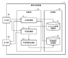
- FIG. 2 is a diagram showing an example of the functional configuration of the recovery support device according to the embodiment of the present invention.
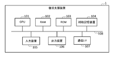
- FIG. 3 is a block diagram showing an example of the hardware configuration of the recovery support device according to the embodiment of the present invention.
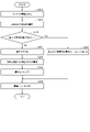
- FIG. 4 is a flowchart showing an example of analysis processing by the recovery support device shown in FIG.
- FIG. 5 is a flowchart showing an example of learning processing by the recovery support device shown in FIG.
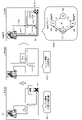
- FIG. 6 is a diagram showing an embodiment of the analysis process.
- FIG. 7 is a diagram showing an embodiment of the learning process.
- FIG. 1 shows an outline of a recovery assisting technique according to an embodiment of the present invention.
- the recovery support technique according to the embodiment includes the analysis algorithm A1 and the learning algorithm A2, and autonomously evolves by the cooperation of the analysis algorithm A1 and the learning algorithm A2.
- the analysis algorithm A1 acquires information related to the disaster or failure as input information IP11 to IP13 when a disaster or failure occurs.
- the input information IP11 to IP13 are input by, for example, a recovery work manager, a person in charge, a decision maker, or the like (hereinafter, simply referred to as “user”), and in this example, the equipment information IP11, the social information IP12, and the like. And disaster information IP13.
- Equipment information IP11 is information about equipment that requires restoration work, for example, equipment position information (for example, latitude and longitude), equipment floor information (for example, how many floors of a building, stairs or elevators). (Availability), and disaster prevention information of equipment (for example, presence / absence of fireproof wall or fireproof wall, earthquake resistance), etc. may be included.
- the social information IP12 includes information on the social environment related to the point where restoration work is required, for example, traffic-related information related to the movement route to the obstacle (traffic jam information, traffic regulation information such as construction, road closure, lane change, etc.). obtain.
- the disaster information IP13 is information representing the content or type of a failure or disaster, and includes, for example, power outage information of an equipment building that requires restoration work.
- the analysis algorithm A1 solves an optimization problem based on the acquired input information IP11 to IP13, and automatically extracts an optimum solution or an approximate solution, thereby also referred to as a procedure plan for recovery work (hereinafter, also referred to as "recommendation information"). ) Is generated.
- the recommendation information generated by the analysis algorithm A1 is output as the output information OP1 and is presented to the user via, for example, a display device (not shown).
- Examples of the recommended information presented include the order of buildings in which power vehicles are deployed, the order of cable restoration, and the like.
- the user determines the actual work procedure (recovery order) based on the presented output information OP1 and acts (AC1).
- the work procedure (AC1) actually adopted for the restoration work may be the same as or different from the output information OP1. For example, if a part of the movement route presented by the output information OP1 is impassable due to a sudden accident, a different movement route will be adopted in the actual restoration work.
- the output information OP1 and the actual work procedure AC1 are different in this way, for example, information on the impassable route is input to the learning algorithm A2 as the feedback FB1.
- the feedback FB1 can be manually input by the user, for example, as information that "this route was impassable".
- the feedback FB1 may be automatically input by a tool (application program) or the like that detects the difference between the output information OP and the actual work procedure AC1.
- the learning algorithm A2 acquires the feedback FB1, determines the difference between the output information OP1 and the actual work procedure AC1, and automatically learns. In other words, the learning algorithm A2 generates a learning result that reflects the feedback FB1 for the output information OP1. The generated learning result is further fed back to the analysis algorithm A1 as feedback FB2.
- the analysis algorithm A1 can utilize the learning result by the learning algorithm A2 when generating a new procedure plan.
- a series of recovery operations such as (i) analysis of coping method, (ii) execution, (iii) reflection of execution result, (iv) next analysis, and so on are algorithmized.
- diaster refers to all situations in which damage occurs due to natural phenomena, accidents, etc. Further, in the present specification, “failure” refers to all events that require recovery work, and damages or failures of individual devices or equipment from events that cover a wide range of damage targets such as power outages, communication failures, network failures, and system failures. , And other abnormalities may be included. However, the terms disaster and disability are not used as a strict distinction herein and may be used interchangeably. Therefore, “disaster recovery” can be replaced with “disaster recovery”, which means returning to the normal state before the disaster or failure or a state equivalent thereto.
- FIG. 2 is a diagram showing an example of the functional configuration of the recovery support device 1 according to the embodiment of the present invention.
- the recovery support device 1 is a computer capable of executing the above-mentioned analysis algorithm and learning algorithm, and may be, for example, a personal computer or a server computer.
- the recovery support device 1 includes a control unit 10, a storage unit 20, an input unit 30, and an output unit 40.
- the input unit 30 receives information related to a disaster or failure that requires recovery work as input information, and performs a process of passing it to the control unit 10.
- the input information may include equipment information, social information, and disaster information.
- the present invention is not limited to this, and other information may be included or may be replaced with other information.
- the input unit 30 receives these input information as information input by a user or the like via an input device such as a keyboard. Alternatively, the input unit 30 can also acquire such information from another device connected via a network or from an external memory such as a USB memory.
- the output unit 40 performs a process of outputting the output data generated by the control unit 10 of the recovery support device 1.
- the output unit 40 causes the user to present the output data by an output device such as a display.
- the output unit 40 can output, for example, the procedure plan generated by the recovery support device 1 as a data file to an external memory or to another device connected via a communication network.
- the storage unit 20 has a function of storing information used or generated in the process of processing by the recovery support device 1, and in this example, the storage unit 20 includes a recommendation result storage unit 21 and a learning history storage unit 22.
- the recommendation result storage unit 21 stores the recommendation information as a procedure plan for the restoration work calculated by the analysis processing unit 11.
- the recommendation information includes a procedure plan calculated by solving an optimization problem by the analysis processing unit 11, for example, information indicating a movement route to a failure point, an order of buildings in which a power supply vehicle is deployed, a cable restoration order, and the like. Can include.
- the learning history storage unit 22 is managed by the learning history management unit 13 and stores the learning results by the learning processing unit 12.
- the learning result reflects the actual work procedure for the corresponding recommendation information, and is stored in association with the input information used when calculating the recommendation information.
- the recommendation result storage unit 21 and the learning history storage unit 22 do not necessarily have to be provided in the recovery support device 1, and may be replaced with an external database or the like.
- the control unit 10 has a function of controlling the entire operation of the recovery support device 1, and includes an analysis processing unit 11, a learning processing unit 12, and a learning history management unit 13.
- the analysis processing unit 11 functions as an analysis unit and generates a procedure plan related to the failure recovery work by solving the optimization problem based on the acquired input information.
- the analysis processing unit 11 also searches the learning history storage unit 22 for the presence or absence of the corresponding learning result based on the input information related to the new failure, and if there is a corresponding learning result, the analysis processing unit 11 searches for the presence or absence of the corresponding learning result. It is read out and the past learning results are used as a procedure plan for new failure recovery work.
- the analysis processing unit 11 outputs the procedure plan to the output unit 40, or stores it in the recommendation result storage unit 21 as the recommendation information. The processing of the analysis processing unit 11 will be further described later.
- the learning processing unit 12 functions as a learning unit, acquires feedback information related to the work procedure actually adopted for the failure recovery work, and generates a learning result that reflects the feedback information for the recommendation information.
- the feedback information includes, for example, information about impassable roads and the like.
- Feedback information also provides information that can identify the corresponding failure or corresponding recommendation information (eg, the date and time of the disaster or failure, the identification name of the disaster or failure, the location of the point where recovery work is required (where the failure occurred)). , Or the date and time when the recommendation information was output, etc.).
- the learning processing unit 12 reads the recommendation information corresponding to the feedback information from the recommendation result storage unit 21 based on the acquired feedback information, and generates a learning result reflecting the feedback information.
- the learning processing unit 12 outputs the learning result to the output unit 40.
- the learning processing unit 12 also outputs the learning result to the learning history management unit 13. The processing of the learning processing unit 12 will be further described later.
- the learning history management unit 13 stores the learning result received from the learning processing unit 12 in the learning history storage unit 22 in association with the corresponding input information.
- FIG. 3 is a block diagram showing an example of the hardware configuration of the recovery support device 1.
- the recovery support device 1 includes a CPU (Central Processing Unit) 101, a RAM (Random Access Memory) 102, a ROM (Read Only Memory) 103, an auxiliary storage device 104, an input device 105, an output device 106, and a communication interface (communication I / O).
- F 107 are provided, which are connected to each other via a bus 108.
- the CPU 101 is an example of a processor and controls the overall operation of the recovery support device 1.
- the CPU 101 expands the program stored in the ROM 103 or the auxiliary storage device 104 into the RAM 102, and by executing this program, operates as the analysis processing unit 11, the learning processing unit 12, and the learning history management unit 13 described above. obtain.
- the CPU 101 may be realized in various other formats including integrated circuits such as ASIC (Application Specific Integrated Circuit) and FPGA (field-programmable gate array). Further, the CPU 101 may include a plurality of processors.
- the auxiliary storage device 104 may be, for example, an HDD (Hard Disk Drive) or an SDD (Solid State Drive).
- the auxiliary storage device 104 non-temporarily stores a program executed by the CPU 101, setting data necessary for executing the program, and the like.
- the auxiliary storage device 104 can also function as a storage unit including the recommendation result storage unit 21 and the learning history storage unit 22 described above.
- the input device 105 includes, for example, a keyboard for a user to input an instruction to the recovery support device 1. Further, the input device 105 may include a reader for reading data to be stored in the storage unit 20 from a memory medium such as a USB memory, and a disk device for reading from the disk medium. Further, the input device 105 may include an image scanner having or not having an OCR (Optical Character Recognition) function.
- OCR Optical Character Recognition
- the output device 106 includes a display that displays output data to be presented to the user and the like from the recovery support device 1, a printer that prints the display, and the like. Further, the output device 106 is a writer for writing data to be input to another information processing device such as a personal computer or a smartphone to a memory medium such as a USB memory, or a disk for writing such data to a disk medium. Can include equipment.
- the communication interface 107 is, for example, an interface for wireless or wired LAN (Local Area Network) communication.
- the recovery support device 1 can, for example, read information from an external database or transmit a generated procedure plan to an external device via a network such as the Internet by means of the communication interface 107.
- the above description is only an example, and the specific hardware configuration of the recovery support device 1 may be appropriately omitted, replaced, or added depending on the embodiment.
- the operation by the recovery support device 1 includes an analysis processing operation by the analysis processing unit 11 and a learning processing operation by the learning processing unit 12.
- FIG. 4 is a flowchart showing the procedure and contents of the analysis processing operation by the analysis processing unit 11. For example, when the control unit 10 receives the input of the input information via the input unit 30, the analysis processing unit 11 causes the analysis processing unit 11 to start the following analysis processing operation.
- step S101 the analysis processing unit 11 acquires the input input information.
- Input information may include equipment information, social information and disaster information.
- step S102 the analysis processing unit 11 performs a process of selecting a start point and an end point.
- the starting point may be defined in advance or may be arbitrarily specified by the user for each analysis.
- the starting point can be a base building for restoration work.
- the end point is selected based on the input information.
- the end point may be a point (failure location) where a failure has occurred, which is determined from the equipment information in the input information.
- step S103 the analysis processing unit 11 determines whether or not there is a usable past learning history. Judgment conditions may be arbitrarily set by the user or the like. For example, the analysis processing unit 11 searches the learning history storage unit 22 for past data having the same conditions such as input information to be used, a start point, an end point, and the content of a failure. If there is no past learning history (NO), the process proceeds to step S104, and the optimum route is searched for in steps S104 to S106. On the other hand, if there is a past learning history (YES), it is read out and the process proceeds to step S107.
- YES past learning history
- step S104 the analysis processing unit 11 generates a directed graph including a start point, an end point, a branch point between them, and the like as vertices (nodes) based on the input information.
- Each branch between the vertices corresponds to a possible procedure, and the weight of each branch is automatically set according to the moving distance, the required time, the required charge, and the like. Alternatively, the user may arbitrarily set the weight.
- step S105 the analysis processing unit 11 constructs an objective function and constraints for setting an optimization problem.
- Objective functions and constraints can be automatically set or set by the user according to the type of disaster, the purpose of recovery, and the like.
- step S106 the analysis processing unit 11 calculates the optimum route by solving the optimization problem based on the above-mentioned directed graph, objective function, and constraint conditions. An example of calculating the optimum route will be described later.
- the analysis processing unit 11 uses the read past learning history as the optimum route in step S107. As a result, the time required for the analysis process can be shortened and the calculation process can be made more efficient.
- step S108 the analysis processing unit 11 outputs the read-out optimum route as the past learning history or the calculated optimum route to the output unit 40 or the recommendation result storage unit 21.
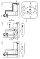
- FIG. 6 is a diagram showing an embodiment of the optimum solution calculation process by the analysis processing unit 11.
- “movement to a failure location” will be described as an example of “recovery work”.
- the control unit 10 can use map data including position information such as latitude and longitude and road information in advance.
- the map IP21M on the left side shows the input information (equipment information and disaster information) IP21 drawn on the map.
- the equipment information includes, as an example, the position information of the failure point TP which is the end point.
- the disaster information includes power outage information as an example. It is assumed that the position of the base building SP, which is the starting point, has been entered in advance.
- Route R1 shows an example of a possible route for moving from the base building SP to the failure point TP.
- the map IP22M in the center shows the input information (social information) IP22 drawn on the map.
- Social information includes traffic jam information as an example.
- the information TJ of the road where the traffic jam is occurring is selected.
- Social information may include other traffic regulation information such as construction information, road closure information, lane change information and the like.
- the map OP2M on the right side shows the output information based on the recommendation information calculated based on the input information IP21 and the input information IP22 by drawing it on the map. More specifically, the analysis processing unit 11 generates the directed graph DG1 based on the input information IP21 and IP2, and calculates the recommendation information by solving the optimization problem.
- the recommendation information is calculated as, for example, the optimum solution of the shortest path problem.
- the directed graph DG1 includes a vertex 1 (N1) as a start point SP, a vertex 4 (N4) as an end point TP, and an intermediate vertex 2 (N2) and a vertex 3 (N3).
- the paths P12, P13, P32, P24, P34 between the vertices drawn on the map OP2M correspond to the branches between the vertices of the directed graph.
- the optimal solution is obtained as a solution that minimizes the objective function, for example, as follows.
- Main problem Find the fastest route to the obstacle.
- Objective function 10x 12 + 15x 13 + 10x 32 + 3x 24 + 25x 34
- x 34 + x 24 1
- the coefficients (weights) of each term of the above objective function are merely examples, and are automatically set according to the distance between points related to the branches (i, j), the required time, the charge, etc., or arbitrarily set by the user or the like. good.
- the optimum solution 13 that minimizes the objective function is obtained.
- the route R2 that reflects the optimum solution is a route of vertex 1 (start point) ⁇ vertex 2 ⁇ vertex 4 (end point).
- the analysis processing unit 11 generates recommendation information using the obtained information of the optimum route R2, and outputs it to the output unit 40 and the recommendation result storage unit 21.
- the recommendation information is presented to the user as output information OP2M, for example, by a display or the like.
- FIG. 5 is a flowchart showing a procedure and contents of a learning process operation by the learning process unit 12. For example, when the control unit 10 receives the input of the feedback information via the input unit 30, the learning processing unit 12 causes the learning processing unit 12 to start the following learning processing operation.
- the learning processing unit 12 acquires the input feedback (FB) information.
- the feedback information may include, for example, information that a particular road is impassable.
- the feedback information further includes information for identifying which recommendation information or which failure the feedback information corresponds to (eg, date and time information).
- step S202 the learning processing unit 12 grasps the route from the feedback information.
- step S203 the learning processing unit 12 reads the recommendation information corresponding to the feedback information from the recommendation result storage unit 21, and generates the directed graph again based on the read recommendation information or the feedback information.
- step S204 the learning processing unit 12 recalculates the optimum route using the objective function and the constraint conditions that reflect the feedback information. For example, when the feedback information indicates an impassable road, the learning processing unit 12 can reflect the feedback information in the constraint condition.
- step S205 the learning processing unit 12 outputs the recalculated route as a learning result to the output unit 40 or the learning history management unit 13.
- FIG. 7 is a diagram showing an embodiment of processing by the learning processing unit 12. Similar to FIG. 6, "movement to a failure point" will be described as an example of “recovery work”. Again, it is assumed that the control unit 10 can use map data including position information such as latitude and longitude and road information in advance.
- the map OP2M on the left side shows the read recommendation result OP2 drawn on the map.
- the map OP2M on the left side of FIG. 7 is the same as the map OP2M on the right side of FIG. 6, and the optimum route R2 obtained by the analysis process of FIG. 6 is drawn.
- the map FB3M in the center shows the feedback information FB3 drawn on the map.
- the feedback information FB3 includes, for example, the information FB31 "earth and sand collapse in the route P12" and the information FB32 "the flooding of the river in the route P32".
- the feedback information FB3 may be input by the user as described above, or may be, for example, read by accessing an external database that manages road traffic information.
- the map OP3M on the right side shows the learning result reflecting the feedback information FB3 for the recommendation result OP2 by drawing it on the map.
- the learning processing unit 12 generates a directed graph DG2 based on the recommendation information OP2 and the feedback information FB3, resets the objective function and the constraint conditions, and obtains the optimum solution again.
- the directed graph DG2 Similar to the directed graph DG1 shown in FIG. 6, the directed graph DG2 has a vertex 1 (N1) as a start point SP, a vertex 4 (N4) as an end point TP, and an intermediate vertex 2 (N2) and a vertex 3 (N3). including.
- the weight of each branch is the same as that of the directed graph DG1 shown in FIG. 6, but the unusable route based on the feedback information FB3 is reflected by a cross.
- the optimum solution is obtained as a solution that minimizes the objective function, for example, as follows.
- Main problem Find the fastest route to the obstacle.
- Objective function 10x 12 + 15x 13 + 10x 32 + 3x 24 + 25x 34
- the main problem and the objective function are the same as those used in the analysis process, but the constraint condition (C5) is added based on the feedback information FB3.
- the learning processing unit 12 outputs the obtained information of the route R3 as a learning result to the output unit 40, or passes it to the learning history management unit 13 and stores it in the learning history storage unit 22. This learning result becomes a learning route for the next disaster.
- the optimization problem used by the analysis processing unit 11 and the learning processing unit 12 is not limited to the shortest path problem exemplified above, and may be appropriately selected according to the type of disaster or failure, the purpose of recovery work, and the like.
- the recovery support device 1 includes an analysis processing unit 11 as an analysis unit and a learning processing unit 12 as a learning unit.
- the analysis processing unit 11 solves the optimization problem based on the input information as the first information related to the first failure, and thereby obtains the first procedure plan for the recovery work of the first failure.
- the learning processing unit 12 acquires feedback information related to the work procedure adopted for the recovery work of the first failure, and generates a learning result reflecting the feedback information for the first procedure plan. Further, when the second failure occurs, the analysis processing unit 11 can generate a second procedure plan related to the recovery work of the second failure by using the learning result.
- the analysis processing unit 11 By the operation of the analysis processing unit 11, a stable procedure plan that does not depend on the skill and know-how of the analyst can be obtained, and the time required for analysis can be shortened by utilizing the past learning results. Further, by the operation of the learning processing unit 12, the feedback information is automatically reflected on the procedure plan, and a stable learning result that does not depend on the skill or know-how of the analyst can be generated.
- the learning result is stored in the learning history storage unit 22 in association with the input information, and the analysis processing unit 11 can read the usable learning result from the learning history storage unit 22 based on the input information.
- the analysis processing unit 11 can generate a first procedure plan by generating a directed graph and obtaining an optimum solution.
- the analysis processing unit 11 can also set constraint conditions based on traffic-related information related to the movement route to the obstacle location and obtain an optimum solution.
- the learning processing unit 12 can obtain a learning result in which the feedback information is reflected in the first procedure plan by setting additional constraints based on the feedback information and recalculating the optimum solution. This makes it possible to generate a more reliable procedure plan in a shorter time.
- the recovery support device 1 analyzes the coping method for the occurrence of a disaster, outputs the recommendation information, and learns based on the judgment of the person.
- the next disaster it is determined whether or not there is a learning result under the same conditions, and if there is a corresponding learning result, it can be utilized.
- the analysis of coping methods and the learning results are accumulated, the number of cases where the learning results that reflect human judgment can be utilized increases. This makes it possible to further simplify the process and speed up the disaster recovery work.
- know-how related to restoration work is systematized, and restoration work can be standardized.
- the recovery support device 1 is not limited to the use of supporting recovery work in the event of a disaster, but generates a work procedure plan necessary for an event that requires some work, and performs the work actually performed. It can also be applied to other uses that generate reflected learning results and make use of past learning results when new events occur. For example, it may be applied to generate a draft inspection procedure when a network failure occurs.
- the targets of optimization in analysis algorithms and learning algorithms are not limited to travel routes, but may be optimization of work procedures that do not involve geographical movement, and may be human, physical, or financial. It may be the optimization of the resource allocation procedure.
- each vertex of the directed graph is not limited to the geographical position, but may represent a process or various resources.
- the functional units 11 to 13 included in the recovery support device 1 described above may be distributed and arranged in a plurality of devices, and the devices may cooperate with each other to perform processing.
- Each functional unit may be realized by using a circuit.
- the circuit may be a dedicated circuit that realizes a specific function, or may be a general-purpose circuit such as a processor.
- the apparatus according to the embodiment of the present invention can also be realized by a computer and a program, and the program can be recorded on a recording medium or provided through a network.
- the method described in the embodiment is a program (software) that can be executed by a computer (computer), for example, a magnetic disk (hard disk, etc.), an optical disk (CD-ROM, DVD, etc.), a semiconductor memory (ROM, RAM). , Flash memory, etc.), and can also be transmitted and distributed via a communication medium.
- the program stored on the medium side also includes a setting program for configuring the software (including not only the execution program but also the table and the data structure) to be executed by the computer in the computer.
- the computer that realizes this device reads the program recorded on the recording medium, builds software by the setting program in some cases, and executes the above-mentioned processing by controlling the operation by this software.
- the recording medium referred to in the present specification is not limited to distribution, and includes storage media such as magnetic disks and semiconductor memories provided in devices connected inside a computer or via a network.
- each storage unit the input / output data format, etc. can be variously modified and implemented without departing from the gist of the present invention.
- the present invention is not limited to the above embodiment, and can be variously modified at the implementation stage without departing from the gist thereof.
- each embodiment may be carried out in combination as appropriate, in which case the combined effect can be obtained.
- the above-described embodiment includes various inventions, and various inventions can be extracted by a combination selected from a plurality of disclosed constituent requirements. For example, even if some constituent elements are deleted from all the constituent elements shown in the embodiment, if the problem can be solved and the effect is obtained, the configuration in which the constituent elements are deleted can be extracted as an invention.
Landscapes
- Engineering & Computer Science (AREA)
- Business, Economics & Management (AREA)
- Human Resources & Organizations (AREA)
- Strategic Management (AREA)
- Economics (AREA)
- Radar, Positioning & Navigation (AREA)
- Remote Sensing (AREA)
- General Physics & Mathematics (AREA)
- Physics & Mathematics (AREA)
- Operations Research (AREA)
- Marketing (AREA)
- Development Economics (AREA)
- Theoretical Computer Science (AREA)
- Game Theory and Decision Science (AREA)
- General Business, Economics & Management (AREA)
- Entrepreneurship & Innovation (AREA)
- Tourism & Hospitality (AREA)
- Quality & Reliability (AREA)
- Automation & Control Theory (AREA)
- Social Psychology (AREA)
- Health & Medical Sciences (AREA)
- General Health & Medical Sciences (AREA)
- Management, Administration, Business Operations System, And Electronic Commerce (AREA)
Abstract
一実施形態に係る復旧支援装置は、分析部と学習部とを備える。分析部は、第1の障害に関連する第1の情報をもとに、最適化問題を解くことによって、第1の障害の復旧作業に係る第1の手順案を生成する。学習部は、上記第1の障害の復旧作業に採用された作業手順に関連するフィードバック情報を取得し、上記第1の手順案に対して上記フィードバック情報を反映した学習結果を生成する。上記分析部はさらに、第2の障害が発生した場合に、上記学習結果を用いて上記第2の障害の復旧作業に係る第2の手順案を生成する。
Description
本発明の実施形態は、復旧支援装置、復旧支援方法およびプログラムに関する。
災害が発生すると、しばしば、被害を受けた設備等の復旧作業が必要となる。例えば、停電が発生したときには、電源車の配備やケーブルの復旧等の作業が必要となる。
従来、災害の発生時には、復旧対象の設備に関する情報、災害に関する情報等に基づいて、復旧作業に必要な分析が手動で行われる。そのような分析の対象には、例えば、優先度や配備順序などが含まれる。
分析の結果は、復旧作業の管理者等に提示される。復旧作業の管理者等は、例えば、提示された分析結果を踏まえて復旧順序等を判断し、復旧作業を実施する。そして、災害復旧(回復)後、反省会などを通してノウハウを保存し、分析手順や分析観点に対するフィードバックを行い、次回の災害発生時に活かす。
関連する技術の一例として、ネットワーク障害の監視システムからの警報をもとに、ネットワークに発生した障害の部位を特定する技術が提案されている(特許文献1参照)。また、障害要因箇所を判定可能なルールを生成する技術も知られている(特許文献2参照)。
しかし、復旧作業の分析には多くの課題が残る。
従来の復旧作業の分析は、一般に手動で行われ、時間を要し、場合によっては困難でさえある。また、分析が手動であるので、分析結果は分析者である人のスキルやノウハウに依存する。さらに、分析者によって分析観点が異なるため、アウトプットの基準が明確でないなど、定量的な効果を示すことができない。そのため、最終的な意思決定者への説明が困難であり、また意思決定者も基準が不明瞭なため判断が困難である。
従来の復旧作業の分析は、一般に手動で行われ、時間を要し、場合によっては困難でさえある。また、分析が手動であるので、分析結果は分析者である人のスキルやノウハウに依存する。さらに、分析者によって分析観点が異なるため、アウトプットの基準が明確でないなど、定量的な効果を示すことができない。そのため、最終的な意思決定者への説明が困難であり、また意思決定者も基準が不明瞭なため判断が困難である。
同様に、分析手順へのフィードバックの反映も手動であり、多くの課題が残る。まずフィードバックを分析手順にどう反映させるかを検討するのに時間を要する。分析手順への反映もまた、人のスキルやノウハウに依存する。また、フィードバック反映後の新しい分析手順での運用も、人のスキルに依存し、定着までに時間を要する。
この発明は、上記事情に着目してなされたもので、その目的とするところは、復旧作業のための作業手順案をより短時間かつより安定した品質で生成できる、復旧支援技術を提供することにある。
上記課題を解決するためにこの発明の第1の態様は、復旧支援装置にあって、第1の障害に関連する第1の情報をもとに最適化問題を解くことによって第1の障害の復旧作業に係る第1の手順案を生成する分析部と、上記第1の障害の復旧作業に採用された作業手順に関連するフィードバック情報を取得し、上記第1の手順案に対して上記フィードバック情報を反映した学習結果を生成する学習部とを備え、上記分析部が、第2の障害が発生した場合に上記学習結果を用いて上記第2の障害の復旧作業に係る第2の手順案を生成するようにしたものである。
この発明の一態様によれば、復旧支援装置は、分析部と学習部とを備える。分析部は、第1の障害に関連する情報をもとに最適化問題を解くことによって第1の障害の復旧作業に係る第1の手順案を生成し、学習部は、第1の手順案に対してフィードバック情報を反映した学習結果を生成する。分析部はさらに、第2の障害が発生した場合に、上記学習結果を用いて第2の障害の復旧作業に係る第2の手順案を生成する。
このように、発明の一態様によれば、障害に関連する情報をもとに自動的に作業手順案が生成され、またフィードバックの反映も自動的に行われるので、必要な時間を短縮しつつ、分析者のスキルやノウハウに依存しない安定した品質の分析結果を提供することができる。さらに、新たな障害が発生した場合には、過去の学習結果を活用して復旧作業の手順案が生成されるので、作業手順案の生成に要する時間をいっそう短縮することができる。
すなわちこの発明の一態様によれば、復旧作業のための作業手順案をより短時間かつより安定した品質で生成できる、復旧支援技術を提供することができる。
以下、図面を参照してこの発明に係わる実施形態を説明する。なお、以降、説明済みの要素と同一または類似の要素には同一または類似の符号を付し、重複する説明については基本的に省略する。例えば、複数の同一または類似の要素が存在する場合に、各要素を区別せずに説明するために共通の符号を用いることがあるし、各要素を区別して説明するために当該共通の符号に加えて枝番号を用いることもある。
[一実施形態]
(1)概要
図1は、この発明の一実施形態に係る復旧支援技術の概要を示す。
図1に示されるように、一実施形態に係る復旧支援技術は、分析アルゴリズムA1と、学習アルゴリズムA2とを含み、分析アルゴリズムA1および学習アルゴリズムA2の協働により、自律的に進化する。
(1)概要
図1は、この発明の一実施形態に係る復旧支援技術の概要を示す。
図1に示されるように、一実施形態に係る復旧支援技術は、分析アルゴリズムA1と、学習アルゴリズムA2とを含み、分析アルゴリズムA1および学習アルゴリズムA2の協働により、自律的に進化する。
まず分析アルゴリズムA1は、災害または障害が発生した場合に、災害または障害に関連する情報をインプット情報IP11~IP13として取得する。インプット情報IP11~IP13は、例えば、復旧作業の管理者、責任者、または意思決定者等(以下、単に「ユーザ」と言う。)によって入力され、この例では、設備情報IP11、社会情報IP12、および災害情報IP13を含む。
設備情報IP11は、復旧作業を要する設備に関する情報であり、例えば、設備の位置情報(例えば緯度経度)、設備のフロア情報(例えば何階建てのビルの何階部分か、階段または昇降機の位置関係や利用可否)、および設備の防災情報(例えば、防火壁や耐火壁の有無、耐震性)等を含み得る。社会情報IP12は、復旧作業を要する地点に関連する社会環境の情報、例えば、障害箇所までの移動経路に係る交通関連情報(渋滞情報、工事や通行止め、車線変更などの交通規制情報)等を含み得る。災害情報IP13は、障害または災害の内容もしくは種別を表す情報であり、例えば、復旧作業を要する設備ビルの停電情報等を含む。
分析アルゴリズムA1は、取得したインプット情報IP11~IP13をもとに、最適化問題を解き、最適解または近似解を自動抽出することによって、復旧作業の手順案(以下、「レコメンド情報」とも言う。)を生成する。
分析アルゴリズムA1によって生成されるレコメンド情報は、アウトプット情報OP1として出力され、例えば、図示しない表示装置等を介してユーザに提示される。提示されるレコメンド情報の一例として、電源車を配備するビルの順序、ケーブルの復旧順序等が含まれる。
ユーザは、提示されたアウトプット情報OP1を踏まえて、実際の作業手順(復旧順序)を判断し、行動する(AC1)。実際に復旧作業に採用される作業手順(AC1)は、アウトプット情報OP1と同一の場合もあるし、異なる場合もある。例えば、アウトプット情報OP1によって提示された移動経路の一部が突発的な事故によって通行不可である場合、実際の復旧作業では異なる移動経路が採用されることになる。このようにアウトプット情報OP1と実際の作業手順AC1とが異なる場合、例えば通行不可経路に関する情報がフィードバックFB1として学習アルゴリズムA2に入力される。フィードバックFB1は、ユーザの手作業によって、例えば「この経路が通行不可であった」という情報として入力され得る。あるいはフィードバックFB1は、アウトプット情報OPと実際の作業手順AC1との差分を検出するツール(アプリケーションプログラム)等によって自動入力されてもよい。
学習アルゴリズムA2は、フィードバックFB1を取得し、アウトプット情報OP1と実際の作業手順AC1との差異を判断し、自動学習する。言い換えれば、学習アルゴリズムA2は、アウトプット情報OP1に対してフィードバックFB1を反映した学習結果を生成する。生成された学習結果は、フィードバックFB2としてさらに分析アルゴリズムA1にフィードバックされる。分析アルゴリズムA1は、新たな手順案を生成する際に、学習アルゴリズムA2による学習結果を活用することができる。
このように、一実施形態によれば、(i)対処方法の分析、(ii)実行、(iii)実行結果の反省、(iv)次の分析・・・という一連の復旧作業をアルゴリズム化して、自律的に、(I)分析、(II)学習、(III)次の分析・・・を行えるようにすることによって、災害復旧までの時間を短縮することができる。加えて、人のノウハウに依存しない、復旧作業の体系化および平準化を可能とする。
なお、本明細書では、「災害」は、自然現象や事故等により被害が発生する事態全般を言う。また本明細書では、「障害」は、復旧作業を要する事象全般を言い、停電、通信障害、ネットワーク障害、システム障害といった、被害対象が広範囲に及ぶ事象から、個々の機器または設備の損傷、故障、その他の異常までも含み得る。ただし、本明細書では、災害と障害という用語が厳密に区別して使用されているわけではなく、交換可能に使用されることもある。したがって、「災害復旧」は、「障害復旧」に置き換えることもでき、災害または障害が発生する前の正常な状態またはそれに準ずる状態に戻すことを言う。
(2)構成
(2-1)機能構成
図2は、この発明の一実施形態に係る復旧支援装置1の機能構成の一例を示す図である。復旧支援装置1は、上記のような分析アルゴリズムおよび学習アルゴリズムを実行可能なコンピュータであり、例えば、パーソナルコンピュータまたはサーバコンピュータであり得る。
(2-1)機能構成
図2は、この発明の一実施形態に係る復旧支援装置1の機能構成の一例を示す図である。復旧支援装置1は、上記のような分析アルゴリズムおよび学習アルゴリズムを実行可能なコンピュータであり、例えば、パーソナルコンピュータまたはサーバコンピュータであり得る。
一実施形態に係る復旧支援装置1は、制御部10と、記憶部20と、入力部30と、出力部40とを備える。
入力部30は、復旧作業を要する災害または障害に関連する情報をインプット情報として受け付け、制御部10に渡す処理を行う。上述したようにインプット情報は、設備情報、社会情報、および災害情報を含み得る。ただしこれに限定されるものではなく、他の情報を含んでもよいし、他の情報に置き換えられてもよい。入力部30は、これらのインプット情報を、キーボード等の入力装置を介してユーザ等により入力される情報として受け付ける。または入力部30は、ネットワークを介して接続された他の装置から、またはUSBメモリなどの外部メモリからこれらの情報を取得することもできる。
出力部40は、復旧支援装置1の制御部10によって生成された出力データを出力する処理を行う。出力部40は、出力データをディスプレイ等の出力装置によりユーザに提示させる。または出力部40は、例えば、復旧支援装置1によって生成された手順案をデータファイルとして、外部メモリに、または通信ネットワークを介して接続された他の装置に出力することもできる。
記憶部20は、復旧支援装置1による処理の過程で使用または生成される情報を記憶する機能を有し、この例では、レコメンド結果記憶部21と、学習履歴記憶部22とを備える。
レコメンド結果記憶部21は、分析処理部11によって算出される復旧作業の手順案としてのレコメンド情報を記憶する。レコメンド情報は、分析処理部11によって最適化問題を解くことによって算出される手順案、例えば、障害箇所までの移動経路、電源車を配備するビルの順序、ケーブルの復旧順序等を示す情報等を含み得る。
学習履歴記憶部22は、学習履歴管理部13によって管理され、学習処理部12による学習結果を記憶する。学習結果は、対応するレコメンド情報に対して実際の作業手順を反映するもので、当該レコメンド情報を算出する際に用いられたインプット情報に関連付けて記憶される。
レコメンド結果記憶部21および学習履歴記憶部22は、必ずしも復旧支援装置1内に設けられる必要はなく、外部のデータベース等に置き換えられてもよい。
制御部10は、復旧支援装置1の全体の動作を制御する機能を有し、分析処理部11と、学習処理部12と、学習履歴管理部13とを備える。
分析処理部11は、分析部として機能し、取得したインプット情報に基づいて最適化問題を解くことによって、障害の復旧作業に係る手順案を生成する。分析処理部11はまた、新たな障害の発生時に、新たな障害に関連するインプット情報に基づき、対応する学習結果の有無を学習履歴記憶部22から検索し、対応する学習結果がある場合にはそれを読み出して、過去の学習結果を新たな障害の復旧作業のための手順案として用いる。分析処理部11は、手順案を出力部40に出力し、またはレコメンド情報としてレコメンド結果記憶部21に記憶させる。分析処理部11の処理についてはさらに後述する。
学習処理部12は、学習部として機能し、障害の復旧作業に実際に採用された作業手順に関連するフィードバック情報を取得し、レコメンド情報に対してフィードバック情報を反映した学習結果を生成する。フィードバック情報は、例えば通行不可道路に関する情報等を含む。フィードバック情報はまた、対応する障害または対応するレコメンド情報を特定可能な情報(例えば、災害または障害の発生日時、災害または障害の識別名、復旧作業を要する地点(障害が発生した箇所)の位置情報、またはレコメンド情報が出力された日時等)を含み得る。学習処理部12は、取得したフィードバック情報に基づき、レコメンド結果記憶部21から当該フィードバック情報に対応するレコメンド情報を読み出し、フィードバック情報を反映した学習結果を生成する。学習処理部12は、学習結果を出力部40に出力する。学習処理部12はまた、学習結果を学習履歴管理部13に出力する。学習処理部12の処理についてはさらに後述する。
学習履歴管理部13は、学習処理部12から受け取った学習結果を、対応するインプット情報に関連付けて学習履歴記憶部22に記憶させる。
(2-2)ハードウェア構成
図3は、復旧支援装置1のハードウェア構成の一例を示すブロック図である。復旧支援装置1は、CPU(Central Processing Unit)101、RAM(Random Access Memory)102、ROM(Read Only Memory)103、補助記憶装置104、入力装置105、出力装置106、および通信インタフェース(通信I/F)107を備え、これらがバス108を介して互いに接続される。
図3は、復旧支援装置1のハードウェア構成の一例を示すブロック図である。復旧支援装置1は、CPU(Central Processing Unit)101、RAM(Random Access Memory)102、ROM(Read Only Memory)103、補助記憶装置104、入力装置105、出力装置106、および通信インタフェース(通信I/F)107を備え、これらがバス108を介して互いに接続される。
CPU101は、プロセッサの一例であり、復旧支援装置1の全体的な動作を制御する。CPU101は、ROM103または補助記憶装置104に記憶されたプログラムをRAM102に展開し、このプログラムを実行することによって、上述した、分析処理部11、学習処理部12、および学習履歴管理部13として動作し得る。CPU101は、ASIC(Application Specific Integrated Circuit)やFPGA(field-programmable gate array)などの集積回路を含む、他の多様な形式で実現されてもよい。またCPU101は、複数のプロセッサを含んでもよい。
補助記憶装置104は、例えば、HDD(Hard Disk Drive)またはSDD(Solid State Drive)であり得る。補助記憶装置104は、CPU101により実行されるプログラムや、プログラムを実行するために必要な設定データなどを非一時的に記憶する。補助記憶装置104は、上述したレコメンド結果記憶部21および学習履歴記憶部22を含む記憶部としても機能し得る。
入力装置105は、例えば、ユーザが復旧支援装置1に対して指示を入力するためのキーボード等を含む。また入力装置105は、記憶部20に格納するべきデータを、USBメモリ等のメモリ媒体から読み出すためのリーダや、ディスク媒体から読み出すためのディスク装置を含み得る。さらに入力装置105は、OCR(Optical Character Recognition)機能を備えたまたは備えないイメージスキャナを含んでもよい。
出力装置106は、復旧支援装置1からユーザ等に提示すべき出力データを表示するディスプレイや、それを印刷するプリンタ等を含む。また、出力装置106は、パーソナルコンピュータやスマートフォン等の他の情報処理装置に入力するべきデータを、USBメモリ等のメモリ媒体に書き込むためのライタや、そのようなデータをディスク媒体に書き込むためのディスク装置を含み得る。
通信インタフェース107は、例えば無線または有線LAN(Local Area Network)通信のためのインタフェースである。復旧支援装置1は、通信インタフェース107により、インターネットなどのネットワークを介して、例えば、外部のデータベースから情報を読み出したり、または生成された手順案を外部の装置に送信したりすることができる。
ただし、上記説明は一例にすぎず、復旧支援装置1の具体的なハードウェア構成は、実施形態に応じて、適宜、構成要素を省略され、置換され、追加されてよい。
(3)動作
次に、以上のように構成された復旧支援装置1による情報処理動作について説明する。
復旧支援装置1による動作は、分析処理部11による分析処理動作と、学習処理部12による学習処理動作とを含む。
次に、以上のように構成された復旧支援装置1による情報処理動作について説明する。
復旧支援装置1による動作は、分析処理部11による分析処理動作と、学習処理部12による学習処理動作とを含む。
(3-1)分析処理
図4は、分析処理部11による分析処理動作の手順および内容を示すフローチャートである。例えば、制御部10は、入力部30を介してインプット情報の入力を受け付けると、分析処理部11に以下の分析処理動作を開始させる。
図4は、分析処理部11による分析処理動作の手順および内容を示すフローチャートである。例えば、制御部10は、入力部30を介してインプット情報の入力を受け付けると、分析処理部11に以下の分析処理動作を開始させる。
まずステップS101において、分析処理部11は、入力されたインプット情報を取得する。インプット情報は、設備情報、社会情報および災害情報を含み得る。
ステップS102において、分析処理部11は、始点および終点を選択する処理を行う。始点は、あらかじめ定義されてもよいし、分析の都度ユーザにより任意に指定されてもよい。例えば、始点は、復旧作業の拠点ビルであり得る。終点は、インプット情報に基づいて選択される。例えば、終点は、インプット情報のうち設備情報から判定される、障害が発生した地点(障害箇所)であり得る。
ステップS103において、分析処理部11は、使用可能な過去の学習履歴の有無を判定する。判定条件は、ユーザ等により任意に設定されてよい。例えば、分析処理部11は、使用するインプット情報や、始点、終点、および障害の内容等の条件が同一の過去データを学習履歴記憶部22から検索する。過去の学習履歴がない場合(NO)、ステップS104に進み、ステップS104~S106において最適ルートの探索を行う。一方、過去の学習履歴がある場合(YES)、それを読み出してステップS107に進む。
ステップS104において、分析処理部11は、インプット情報をもとに、始点と、終点と、それらの間の分岐点等を頂点(ノード)として含む有向グラフを生成する。頂点間の各枝は、とりうる手順に対応し、各枝の重みは、移動距離、所要時間、所要料金等に応じて自動設定される。あるいはユーザが任意に重みを設定可能としてもよい。
ステップS105において、分析処理部11は、最適化問題を設定するための目的関数および制約条件を構築する。目的関数および制約条件は、災害の種別や復旧の目的等に応じて自動設定され、あるいはユーザにより設定され得る。
ステップS106において、分析処理部11は、上記の有向グラフ、目的関数および制約条件をもとに、最適化問題を解くことによって最適ルートを計算する。最適ルートの計算例については後述する。
一方、過去の学習履歴がある場合、分析処理部11は、ステップS107において、読み出した過去の学習履歴を最適ルートとして用いる。これによって、分析処理に要する時間を短縮し、計算処理を効率化することができる。
次いでステップS108において、分析処理部11は、読み出された過去の学習履歴としての最適ルート、または計算された最適ルートを、出力部40またはレコメンド結果記憶部21に出力する。
図6は、分析処理部11による最適解算出処理の一実施例を示す図である。
ここでは、「復旧作業」として「障害箇所までの移動」を例に挙げて説明する。なお、以下の処理において、制御部10は、あらかじめ緯度経度等の位置情報および道路情報を含むマップデータを利用可能であるものとする。
ここでは、「復旧作業」として「障害箇所までの移動」を例に挙げて説明する。なお、以下の処理において、制御部10は、あらかじめ緯度経度等の位置情報および道路情報を含むマップデータを利用可能であるものとする。
左側のマップIP21Mは、インプット情報(設備情報および災害情報)IP21をマップに描画して示すものである。設備情報は、一例として、終点となる障害箇所TPの位置情報を含む。災害情報は、一例として停電情報を含む。始点となる拠点ビルSPの位置は、あらかじめ入力されているものとする。ルートR1は、拠点ビルSPから障害箇所TPに移動するために可能なルートの一例を示す。
中央のマップIP22Mは、インプット情報(社会情報)IP22をマップに描画して示すものである。社会情報は、一例として渋滞情報を含む。ここでは、渋滞が発生している道路の情報TJが選択されている。社会情報は、工事情報、通行止め情報、車線変更情報などの他の交通規制情報を含み得る。
右側のマップOP2Mは、インプット情報IP21およびインプット情報IP22をもとに算出されるレコメンド情報に基づくアウトプット情報をマップに描画して示すものである。より具体的には、分析処理部11は、インプット情報IP21およびIP2に基づく有向グラフDG1を生成し、最適化問題を解くことによってレコメンド情報を算出する。レコメンド情報は、例えば、最短経路問題の最適解として算出される。有向グラフDG1は、始点SPとしての頂点1(N1)と、終点TPとしての頂点4(N4)と、中間の頂点2(N2)および頂点3(N3)を含む。マップOP2M上に描かれた各頂点間の経路P12,P13,P32,P24,P34は、有向グラフの各頂点間の枝に対応する。
最適解は、例えば以下のように、目的関数を最小化する解として求められる。
主問題:最速で障害箇所までに行けるルートを求める。
目的関数:10x12+15x13+10x32+3x24+25x34
制約条件:
(C1)x12+x13=1
(C2)x13=x32+x34
(C3)x12+x32=x24
(C4)x34+x24=1
ここで、x12,x13,x32,x24,x34≧0
xij∈{0,1};枝(i,j)を通る場合xij=1,通らない場合xij=0
主問題:最速で障害箇所までに行けるルートを求める。
目的関数:10x12+15x13+10x32+3x24+25x34
制約条件:
(C1)x12+x13=1
(C2)x13=x32+x34
(C3)x12+x32=x24
(C4)x34+x24=1
ここで、x12,x13,x32,x24,x34≧0
xij∈{0,1};枝(i,j)を通る場合xij=1,通らない場合xij=0
渋滞情報TJは、制約条件に反映され得る。例えば、頂点3から頂点2への経路P32が渋滞である場合、制約条件にX32=0を追加する。上記目的関数の各項の係数(重み)は、単なる一例であり、枝(i,j)に係る地点間の距離、所要時間、料金等に応じて自動設定またはユーザ等により任意に設定されてよい。
上記の例では、目的関数を最小化する最適解=13と得られる。このとき、
x12 =1,x13 =0,x32 =0,x24 =1,x34 =0
であり、x12 =1およびx24 =1であるので、最適解を反映するルートR2は、頂点1(始点)→頂点2→頂点4(終点)というルートとなる。
x12 =1,x13 =0,x32 =0,x24 =1,x34 =0
であり、x12 =1およびx24 =1であるので、最適解を反映するルートR2は、頂点1(始点)→頂点2→頂点4(終点)というルートとなる。
分析処理部11は、得られた最適ルートR2の情報を用いてレコメンド情報を生成し、出力部40およびレコメンド結果記憶部21に出力する。レコメンド情報は、例えば、アウトプット情報OP2Mとしてディスプレイ等によりユーザに提示される。
(3-2)学習処理
図5は、学習処理部12による学習処理動作の手順および内容を示すフローチャートである。例えば、制御部10は、入力部30を介してフィードバック情報の入力を受け付けると、学習処理部12に以下の学習処理動作を開始させる。
図5は、学習処理部12による学習処理動作の手順および内容を示すフローチャートである。例えば、制御部10は、入力部30を介してフィードバック情報の入力を受け付けると、学習処理部12に以下の学習処理動作を開始させる。
ステップS201において、学習処理部12は、入力されたフィードバック(FB)情報を取得する。フィードバック情報は、例えば、特定の道路が通行不可という情報を含み得る。フィードバック情報はさらに、当該フィードバック情報がどのレコメンド情報またはどの障害に対応するかを特定するための情報(例えば、日時情報)を含む。
ステップS202において、学習処理部12は、フィードバック情報からルートを把握する。
ステップS203において、学習処理部12は、フィードバック情報に対応するレコメンド情報をレコメンド結果記憶部21から読み出し、読み出したレコメンド情報またはフィードバック情報に基づいて再び有向グラフを生成する。
ステップS204において、学習処理部12は、フィードバック情報を反映した目的関数および制約条件を用いて最適ルートを再計算する。例えばフィードバック情報が通行不可の道路を示す場合、学習処理部12は、当該フィードバック情報を制約条件に反映することができる。
ステップS205において、学習処理部12は、再計算したルートを学習結果として出力部40または学習履歴管理部13に出力する。
図7は、学習処理部12による処理の一実施例を示す図である。
図6と同様、「復旧作業」として「障害箇所までの移動」を例に挙げて説明する。やはり、制御部10は、あらかじめ緯度経度等の位置情報および道路情報を含むマップデータを利用可能であるものとする。
図6と同様、「復旧作業」として「障害箇所までの移動」を例に挙げて説明する。やはり、制御部10は、あらかじめ緯度経度等の位置情報および道路情報を含むマップデータを利用可能であるものとする。
左側のマップOP2Mは、読み出したレコメンド結果OP2をマップに描画して示すものである。この例では、図7の左側のマップOP2Mは、図6の右側のマップOP2Mと同じものであり、図6の分析処理で得られた最適ルートR2が描かれている。
中央のマップFB3Mは、フィードバック情報FB3をマップに描画して示すものである。フィードバック情報FB3は、一例として、「経路P12内で土砂くずれ」という情報FB31と、「経路P32内で川の氾濫」という情報FB32を含む。フィードバック情報FB3は、上述のようにユーザによって入力されてもよいし、例えば、道路交通情報を管理する外部データベースにアクセスして読み出されたものであってもよい。
右側のマップOP3Mは、レコメンド結果OP2に対してフィードバック情報FB3を反映した学習結果をマップに描画して示すものである。学習処理部12は、レコメンド情報OP2とフィードバック情報FB3に基づいて、有向グラフDG2を生成し、目的関数および制約条件を再設定して、再び最適解を求める。有向グラフDG2は、図6に示した有向グラフDG1と同様に、始点SPとしての頂点1(N1)と、終点TPとしての頂点4(N4)と、中間の頂点2(N2)および頂点3(N3)を含む。この例では、有向グラフDG2において、各枝の重みは図6に示した有向グラフDG1と同じであるが、フィードバック情報FB3に基づく使用不可経路が×印で反映されている。
最適解は、例えば以下のように目的関数を最小化する解として求められる。
主問題:最速で障害箇所までに行けるルートを求める。
目的関数:10x12+15x13+10x32+3x24+25x34
制約条件:
(C1)x12+x13=1
(C2)x13=x32+x34
(C3)x12+x32=x24
(C4)x34+x24=1
(C5)x12=0,x32=0
ここで、x12,x13,x32,x24,x34≧0
xij∈{0,1};枝(i,j)を通る場合xij=1,通らない場合xij=0
主問題:最速で障害箇所までに行けるルートを求める。
目的関数:10x12+15x13+10x32+3x24+25x34
制約条件:
(C1)x12+x13=1
(C2)x13=x32+x34
(C3)x12+x32=x24
(C4)x34+x24=1
(C5)x12=0,x32=0
ここで、x12,x13,x32,x24,x34≧0
xij∈{0,1};枝(i,j)を通る場合xij=1,通らない場合xij=0
この例では、主問題および目的関数は、分析処理で使用したものと同じであるが、フィードバック情報FB3に基づいて制約条件(C5)が追加されている。
この例では、目的関数を最小化する最適解=40と得られる。このとき、
x12 =0,x13 =1,x32 =0,x24 =0,x34 =1
であり、x13 =1およびx34 =1であるので、最適解を反映する学習後のルートR3は、頂点1(始点)→頂点3→頂点4(終点)というルートとなる。
x12 =0,x13 =1,x32 =0,x24 =0,x34 =1
であり、x13 =1およびx34 =1であるので、最適解を反映する学習後のルートR3は、頂点1(始点)→頂点3→頂点4(終点)というルートとなる。
学習処理部12は、得られたルートR3の情報を学習結果として出力部40に出力し、または学習履歴管理部13に渡して学習履歴記憶部22に記憶させる。この学習結果は、次の災害に向けた学習ルートとなる。
分析処理部11および学習処理部12によって用いられる最適化問題は、以上で例示した最短経路問題に限定されず、災害または障害の種別や復旧作業の目的等に応じて適切に選択されてよい。
(4)効果
以上詳述したように、この発明の一実施形態に係る復旧支援装置1は、分析部としての分析処理部11と、学習部としての学習処理部12とを備える。分析処理部11は、第1の障害に関連する第1の情報としてのインプット情報をもとに、最適化問題を解くことによって、前記第1の障害の復旧作業に係る第1の手順案を生成する。学習処理部12は、第1の障害の復旧作業に採用された作業手順に関連するフィードバック情報を取得し、第1の手順案に対してフィードバック情報を反映した学習結果を生成する。分析処理部11はさらに、第2の障害が発生した場合に、上記学習結果を用いて第2の障害の復旧作業に係る第2の手順案を生成することができる。
以上詳述したように、この発明の一実施形態に係る復旧支援装置1は、分析部としての分析処理部11と、学習部としての学習処理部12とを備える。分析処理部11は、第1の障害に関連する第1の情報としてのインプット情報をもとに、最適化問題を解くことによって、前記第1の障害の復旧作業に係る第1の手順案を生成する。学習処理部12は、第1の障害の復旧作業に採用された作業手順に関連するフィードバック情報を取得し、第1の手順案に対してフィードバック情報を反映した学習結果を生成する。分析処理部11はさらに、第2の障害が発生した場合に、上記学習結果を用いて第2の障害の復旧作業に係る第2の手順案を生成することができる。
分析処理部11の動作により、分析者のスキルやノウハウに依存しない安定した手順案が得られるとともに、過去の学習結果を活用することによって分析に要する時間を短縮することもできる。また、学習処理部12の動作により、フィードバック情報が手順案に対して自動的に反映され、分析者のスキルやノウハウに依存しない安定した学習結果を生成することができる。
学習結果は、インプット情報に関連付けて学習履歴記憶部22に記憶され、分析処理部11は、インプット情報に基づいて、使用し得る学習結果を学習履歴記憶部22から読み出すことができる。分析処理部11は、有向グラフを生成し、最適解を得ることによって第1の手順案を生成することができる。分析処理部11はまた、障害箇所までの移動経路に係る交通関連情報をもとに制約条件を設定して最適解を得ることもできる。学習処理部12は、フィードバック情報に基づく追加の制約条件を設定して最適解を再計算することによって、第1の手順案にフィードバック情報を反映した学習結果を得ることができる。これにより、より信頼性の高い手順案をより短時間で生成することができるようになる。
このように、一実施形態に係る復旧支援装置1は、災害の発生に対する対処方法の分析およびレコメンド情報の出力と、それに対する人の判断を踏まえた学習を行う。次の災害の発生時には、同じ条件の学習結果の有無が判定され、該当する学習結果があれば活用することができる。対処方法の分析および学習結果が蓄積されていくにつれ、人の判断を反映した学習結果を活用できるケースが増加する。これにより、処理をさらに簡略化できるようになり、災害復旧作業の迅速化を図ることができる。また、復旧作業に係るノウハウが体系化され、復旧作業の平準化を図ることもできる。
[他の実施形態]
なお、この発明は上記実施形態に限定されるものではない。
例えば、復旧支援装置1は、災害発生時の復旧作業の支援用途のみに限定されるものではなく、何らかの作業を要する事象に対して必要な作業手順案を生成し、実際に行われた作業を反映した学習結果を生成し、新たな事象の発生時に過去の学習結果を利用可能な他の用途にも適用可能である。例えば、ネットワーク障害発生時の検査手順案の生成に適用されてもよい。また同様に、分析アルゴリズムおよび学習アルゴリズムにおける最適化の対象は、移動経路のみに限られず、地理的移動を伴わない作業手順の最適化であってもよいし、人的、物的、または金銭的な資源の配置手順の最適化であってもよい。同様に、有向グラフの各頂点は、地理的な位置に限られるものではなく、工程や各種資源を表すものであってもよい。
なお、この発明は上記実施形態に限定されるものではない。
例えば、復旧支援装置1は、災害発生時の復旧作業の支援用途のみに限定されるものではなく、何らかの作業を要する事象に対して必要な作業手順案を生成し、実際に行われた作業を反映した学習結果を生成し、新たな事象の発生時に過去の学習結果を利用可能な他の用途にも適用可能である。例えば、ネットワーク障害発生時の検査手順案の生成に適用されてもよい。また同様に、分析アルゴリズムおよび学習アルゴリズムにおける最適化の対象は、移動経路のみに限られず、地理的移動を伴わない作業手順の最適化であってもよいし、人的、物的、または金銭的な資源の配置手順の最適化であってもよい。同様に、有向グラフの各頂点は、地理的な位置に限られるものではなく、工程や各種資源を表すものであってもよい。
また、上述した復旧支援装置1が備える各機能部11~13を複数の装置に分散配置し、これらの装置が互いに連携することにより処理を行うようにしてもよい。各機能部は、回路を用いることで実現されてもよい。回路は、特定の機能を実現する専用回路であってもよいし、プロセッサのような汎用回路であってもよい。
さらに、以上で説明した各処理の流れは、説明した手順に限定されるものではなく、いくつかのステップの順序が入れ替えられてもよいし、いくつかのステップが同時並行で実施されてもよい。また、以上で説明した一連の処理は、時間的に連続して実行される必要はなく、各ステップは任意のタイミングで実行されてもよい。
本発明の実施形態に係る装置は、コンピュータとプログラムによっても実現でき、プログラムを記録媒体に記録することも、ネットワークを通して提供することも可能である。例えば、実施形態に記載した手法は、計算機(コンピュータ)に実行させることができるプログラム(ソフトウェア)として、例えば磁気ディスク(ハードディスク等)、光ディスク(CD-ROM、DVD等)、半導体メモリ(ROM、RAM、フラッシュメモリ等)等の記録媒体に格納し、また通信媒体により伝送して頒布することもできる。なお、媒体側に格納されるプログラムには、計算機に実行させるソフトウェア(実行プログラムのみならずテーブルやデータ構造も含む)を計算機内に構成させる設定プログラムをも含む。本装置を実現する計算機は、記録媒体に記録されたプログラムを読み込み、また場合により設定プログラムによりソフトウェアを構築し、このソフトウェアによって動作が制御されることにより上述した処理を実行する。なお、本明細書でいう記録媒体は、頒布用に限らず、計算機内部あるいはネットワークを介して接続される機器に設けられた磁気ディスクや半導体メモリ等の記憶媒体を含むものである。
その他、各記憶部の構成、入出力されるデータ形式等についても、この発明の要旨を逸脱しない範囲で種々変形して実施可能である。
要するにこの発明は、上記実施形態に限定されるものではなく、実施段階ではその要旨を逸脱しない範囲で種々に変形することが可能である。また、各実施形態は適宜組み合わせて実施してもよく、その場合組み合わせた効果が得られる。更に、上記実施形態には種々の発明が含まれており、開示される複数の構成要件から選択された組み合わせにより種々の発明が抽出され得る。例えば、実施形態に示される全構成要件からいくつかの構成要件が削除されても、課題が解決でき、効果が得られる場合には、この構成要件が削除された構成が発明として抽出され得る。
1 復旧支援装置
10 制御部
11 分析処理部
12 学習処理部
13 学習履歴管理部
20 記憶部
21 レコメンド結果記憶部
22 学習履歴記憶部
30 入力部
40 出力部
101 CPU
102 RAM
103 ROM
104 補助記憶装置
105 入力装置
106 出力装置
107 通信インタフェース
108 バス
10 制御部
11 分析処理部
12 学習処理部
13 学習履歴管理部
20 記憶部
21 レコメンド結果記憶部
22 学習履歴記憶部
30 入力部
40 出力部
101 CPU
102 RAM
103 ROM
104 補助記憶装置
105 入力装置
106 出力装置
107 通信インタフェース
108 バス
Claims (8)
- 第1の障害に関連する第1の情報をもとに、最適化問題を解くことによって、前記第1の障害の復旧作業に係る第1の手順案を生成する、分析部と、
前記第1の障害の復旧作業に採用された作業手順に関連するフィードバック情報を取得し、前記第1の手順案に対して前記フィードバック情報を反映した学習結果を生成する、学習部と、
を備え、
前記分析部は、第2の障害が発生した場合に、前記学習結果を用いて前記第2の障害の復旧作業に係る第2の手順案を生成する、
復旧支援装置。 - 前記分析部は、前記第1の障害に関連する前記第1の情報と、前記第2の障害に関連する第2の情報との対比に基づき、前記学習結果を前記第1の情報に関連付けて記憶する記憶部から前記第2の障害の復旧作業に使用すべき学習結果を読み出し、読み出した学習結果を前記第2の手順案として用いる、
請求項1に記載の復旧支援装置。 - 前記分析部は、前記第1の情報に基づいて有向グラフを生成し、前記有向グラフに関する第1の最適解を算出することによって前記第1の手順案を生成する、
請求項1に記載の復旧支援装置。 - 前記第1の情報は、前記第1の障害の復旧作業に係る第1の地点に関する位置情報および前記第1の地点までの移動経路に関する情報を含み、
前記分析部は、前記有向グラフをもとに前記第1の地点に移動するための最短経路問題を解くことによって前記第1の手順案を生成する、
請求項3に記載の復旧支援装置。 - 前記第1の情報はさらに、前記第1の地点までの移動経路に係る交通関連情報を含み、
前記分析部は、前記有向グラフに対して前記交通関連情報に基づく第1の制約条件を設定し、当該第1の制約条件のもとで前記最短経路問題を解くことによって前記第1の手順案を生成する、
請求項4に記載の復旧支援装置。 - 前記学習部は、前記フィードバック情報に基づいて前記有向グラフに適用すべき第2の制約条件を設定し、さらに前記第2の制約条件のもとで前記有向グラフから算出される第2の最適解を前記学習結果として用いる、
請求項5に記載の復旧支援装置。 - 第1の障害に関連する第1の情報をもとに、最適化問題を解くことによって、前記第1の障害の復旧作業に係る第1の手順案を生成することと、
前記第1の障害の復旧作業に採用された作業手順に関連するフィードバック情報を取得し、前記第1の手順案に対して前記フィードバック情報を反映した学習結果を生成することと、
第2の障害が発生した場合に、前記学習結果を用いて前記第2の障害の復旧作業に係る第2の手順案を生成することと、
を備える、復旧支援方法。 - 請求項1乃至6のいずれか一項に記載の装置の各部による処理をコンピュータに実行させるプログラム。
Priority Applications (3)
| Application Number | Priority Date | Filing Date | Title |
|---|---|---|---|
| PCT/JP2020/036409 WO2022064657A1 (ja) | 2020-09-25 | 2020-09-25 | 復旧支援装置、復旧支援方法およびプログラム |
| US18/027,258 US20230359949A1 (en) | 2020-09-25 | 2020-09-25 | Recovery support apparatus, recovery support method, and program |
| JP2022551065A JP7452680B2 (ja) | 2020-09-25 | 2020-09-25 | 復旧支援装置、復旧支援方法およびプログラム |
Applications Claiming Priority (1)
| Application Number | Priority Date | Filing Date | Title |
|---|---|---|---|
| PCT/JP2020/036409 WO2022064657A1 (ja) | 2020-09-25 | 2020-09-25 | 復旧支援装置、復旧支援方法およびプログラム |
Publications (1)
| Publication Number | Publication Date |
|---|---|
| WO2022064657A1 true WO2022064657A1 (ja) | 2022-03-31 |
Family
ID=80846422
Family Applications (1)
| Application Number | Title | Priority Date | Filing Date |
|---|---|---|---|
| PCT/JP2020/036409 Ceased WO2022064657A1 (ja) | 2020-09-25 | 2020-09-25 | 復旧支援装置、復旧支援方法およびプログラム |
Country Status (3)
| Country | Link |
|---|---|
| US (1) | US20230359949A1 (ja) |
| JP (1) | JP7452680B2 (ja) |
| WO (1) | WO2022064657A1 (ja) |
Cited By (5)
| Publication number | Priority date | Publication date | Assignee | Title |
|---|---|---|---|---|
| JP7222441B1 (ja) | 2022-08-05 | 2023-02-15 | 富士電機株式会社 | 分析装置、分析方法及びプログラム |
| JPWO2023238225A1 (ja) * | 2022-06-07 | 2023-12-14 | ||
| WO2024121896A1 (ja) * | 2022-12-05 | 2024-06-13 | 日本電信電話株式会社 | 学習装置、選択装置、学習方法、選択方法、及びプログラム |
| WO2024127508A1 (ja) * | 2022-12-13 | 2024-06-20 | 日本電信電話株式会社 | 配置最適化装置、配置最適化方法、および配置最適化プログラム |
| WO2025191741A1 (ja) * | 2024-03-13 | 2025-09-18 | Ntt株式会社 | ネットワーク管理装置、方法およびプログラム |
Citations (4)
| Publication number | Priority date | Publication date | Assignee | Title |
|---|---|---|---|---|
| US20170059331A1 (en) * | 2015-08-31 | 2017-03-02 | Sap Se | Route planner for transportation systems |
| JP2018137724A (ja) * | 2017-02-23 | 2018-08-30 | 日本電信電話株式会社 | 経路探索装置、経路探索方法、及びプログラム |
| JP2019057139A (ja) * | 2017-09-21 | 2019-04-11 | 日本電気株式会社 | 運用管理システム、監視サーバ、方法およびプログラム |
| JP2019125940A (ja) * | 2018-01-17 | 2019-07-25 | 日本電信電話株式会社 | 作業手順提示装置及び作業手順提示方法、並びに、自動制御装置及び自動制御方法 |
Family Cites Families (5)
| Publication number | Priority date | Publication date | Assignee | Title |
|---|---|---|---|---|
| JP4170128B2 (ja) * | 2003-04-03 | 2008-10-22 | 三菱電機株式会社 | 経路案内学習装置 |
| JP4859558B2 (ja) | 2006-06-30 | 2012-01-25 | 株式会社日立製作所 | コンピュータシステムの制御方法及びコンピュータシステム |
| JP6024396B2 (ja) * | 2012-11-05 | 2016-11-16 | 株式会社デンソー | 経路案内システム、経路案内装置、及び走行経路送信装置 |
| US20170279957A1 (en) * | 2013-08-23 | 2017-09-28 | Cellepathy Inc. | Transportation-related mobile device context inferences |
| US12112283B1 (en) * | 2019-02-15 | 2024-10-08 | State Farm Mutual Automobile Insurance Company | Systems and methods for dynamically generating optimal routes and routed vehicle analytics |
-
2020
- 2020-09-25 WO PCT/JP2020/036409 patent/WO2022064657A1/ja not_active Ceased
- 2020-09-25 JP JP2022551065A patent/JP7452680B2/ja active Active
- 2020-09-25 US US18/027,258 patent/US20230359949A1/en not_active Abandoned
Patent Citations (4)
| Publication number | Priority date | Publication date | Assignee | Title |
|---|---|---|---|---|
| US20170059331A1 (en) * | 2015-08-31 | 2017-03-02 | Sap Se | Route planner for transportation systems |
| JP2018137724A (ja) * | 2017-02-23 | 2018-08-30 | 日本電信電話株式会社 | 経路探索装置、経路探索方法、及びプログラム |
| JP2019057139A (ja) * | 2017-09-21 | 2019-04-11 | 日本電気株式会社 | 運用管理システム、監視サーバ、方法およびプログラム |
| JP2019125940A (ja) * | 2018-01-17 | 2019-07-25 | 日本電信電話株式会社 | 作業手順提示装置及び作業手順提示方法、並びに、自動制御装置及び自動制御方法 |
Cited By (7)
| Publication number | Priority date | Publication date | Assignee | Title |
|---|---|---|---|---|
| JPWO2023238225A1 (ja) * | 2022-06-07 | 2023-12-14 | ||
| JP7683824B2 (ja) | 2022-06-07 | 2025-05-27 | 日本電信電話株式会社 | ルート探索装置、ルート探索方法、およびプログラム |
| JP7222441B1 (ja) | 2022-08-05 | 2023-02-15 | 富士電機株式会社 | 分析装置、分析方法及びプログラム |
| JP2024022159A (ja) * | 2022-08-05 | 2024-02-16 | 富士電機株式会社 | 分析装置、分析方法及びプログラム |
| WO2024121896A1 (ja) * | 2022-12-05 | 2024-06-13 | 日本電信電話株式会社 | 学習装置、選択装置、学習方法、選択方法、及びプログラム |
| WO2024127508A1 (ja) * | 2022-12-13 | 2024-06-20 | 日本電信電話株式会社 | 配置最適化装置、配置最適化方法、および配置最適化プログラム |
| WO2025191741A1 (ja) * | 2024-03-13 | 2025-09-18 | Ntt株式会社 | ネットワーク管理装置、方法およびプログラム |
Also Published As
| Publication number | Publication date |
|---|---|
| US20230359949A1 (en) | 2023-11-09 |
| JP7452680B2 (ja) | 2024-03-19 |
| JPWO2022064657A1 (ja) | 2022-03-31 |
Similar Documents
| Publication | Publication Date | Title |
|---|---|---|
| JP7452680B2 (ja) | 復旧支援装置、復旧支援方法およびプログラム | |
| JP5700068B2 (ja) | 障害管理方法、障害管理装置及びコンピュータプログラム | |
| Ukkusuri et al. | A methodology to assess the criticality of highway transportation networks | |
| US7647286B2 (en) | System and method for managing a chaotic event by providing optimal and adaptive sequencing of decision sets with supporting data | |
| US7653609B2 (en) | System and method for managing a chaotic event by optimizing decision subdivisions subject to multidimensional constraints | |
| US7647288B2 (en) | System and method for optimally customizable and adaptive personalized information display for information associated with managing a chaotic event | |
| Sakuraba et al. | Road network emergency accessibility planning after a major earthquake | |
| Somy et al. | Resilience-based mathematical model to restore disrupted road-bridge transportation networks | |
| JP7510311B2 (ja) | 災害対応支援方法および災害対応支援システム | |
| US20080177687A1 (en) | System and method for optimal and adaptive process unification of decision support functions associated with managing a chaotic event | |
| CN110752944B (zh) | 告警派单方法及装置 | |
| US20220138871A1 (en) | Outage restoration time prediction during weather events and optimized solutions for recovery | |
| Bell et al. | Modelling the marine transport resilience of Vancouver Island in a Cascadia subduction zone earthquake scenario | |
| Esposito Amideo et al. | An integrated user‐system approach for shelter location and evacuation routing | |
| Huang et al. | Network reliability analysis on casualty rescue for natural disaster evaluation | |
| WO2016075931A1 (ja) | 避難予測システム、避難予測方法及びコンピュータ読み取り可能記録媒体 | |
| WO2016075933A1 (ja) | 避難予測システム、モデル生成装置、予測装置、避難予測方法及びコンピュータ読み取り可能記録媒体 | |
| Issac et al. | Shortest path problem with arc failure scenarios | |
| US20170177755A1 (en) | System and method for dynamically adjusting an emergency coordination simulation system | |
| JP7568088B2 (ja) | ネットワーク管理装置、方法およびプログラム | |
| A Konstantinidou et al. | A multi-objective network design model for post-disaster transportation network management | |
| Chen et al. | Toward community-centered planning of infrastructure restorations by integrating community demographics and public facilities | |
| JP7736163B2 (ja) | 緊急車両通行支援装置、緊急車両通行支援方法、及び、緊急車両通行支援プログラム | |
| Mehrabani et al. | Impact of connected and autonomous vehicles on road network resilience in Belgium | |
| Yu | On-demand mobility services for infrastructure and community resilience: a review toward synergistic disaster response systems |
Legal Events
| Date | Code | Title | Description |
|---|---|---|---|
| 121 | Ep: the epo has been informed by wipo that ep was designated in this application |
Ref document number: 20955251 Country of ref document: EP Kind code of ref document: A1 |
|
| ENP | Entry into the national phase |
Ref document number: 2022551065 Country of ref document: JP Kind code of ref document: A |
|
| NENP | Non-entry into the national phase |
Ref country code: DE |
|
| 122 | Ep: pct application non-entry in european phase |
Ref document number: 20955251 Country of ref document: EP Kind code of ref document: A1 |