WO2022064615A1 - 空気調和機および空気調和システム - Google Patents
空気調和機および空気調和システム Download PDFInfo
- Publication number
- WO2022064615A1 WO2022064615A1 PCT/JP2020/036109 JP2020036109W WO2022064615A1 WO 2022064615 A1 WO2022064615 A1 WO 2022064615A1 JP 2020036109 W JP2020036109 W JP 2020036109W WO 2022064615 A1 WO2022064615 A1 WO 2022064615A1
- Authority
- WO
- WIPO (PCT)
- Prior art keywords
- information
- heat distribution
- user
- setting
- air conditioner
- Prior art date
Links
- 238000004378 air conditioning Methods 0.000 title claims abstract description 7
- 230000005540 biological transmission Effects 0.000 claims description 22
- 238000010586 diagram Methods 0.000 description 13
- 238000000034 method Methods 0.000 description 10
- 238000001514 detection method Methods 0.000 description 7
- 238000013459 approach Methods 0.000 description 6
- 238000004891 communication Methods 0.000 description 6
- 230000000694 effects Effects 0.000 description 6
- 230000006870 function Effects 0.000 description 3
- 230000007704 transition Effects 0.000 description 3
- 238000009423 ventilation Methods 0.000 description 3
- 238000005192 partition Methods 0.000 description 2
- 238000005070 sampling Methods 0.000 description 2
- 238000005422 blasting Methods 0.000 description 1
- 238000007664 blowing Methods 0.000 description 1
- 238000010411 cooking Methods 0.000 description 1
- 238000005516 engineering process Methods 0.000 description 1
- 230000010365 information processing Effects 0.000 description 1
- 238000009434 installation Methods 0.000 description 1
- 230000002123 temporal effect Effects 0.000 description 1
- 238000001931 thermography Methods 0.000 description 1
Images


Classifications
-
- F—MECHANICAL ENGINEERING; LIGHTING; HEATING; WEAPONS; BLASTING
- F24—HEATING; RANGES; VENTILATING
- F24F—AIR-CONDITIONING; AIR-HUMIDIFICATION; VENTILATION; USE OF AIR CURRENTS FOR SCREENING
- F24F11/00—Control or safety arrangements
- F24F11/62—Control or safety arrangements characterised by the type of control or by internal processing, e.g. using fuzzy logic, adaptive control or estimation of values
- F24F11/63—Electronic processing
- F24F11/64—Electronic processing using pre-stored data
-
- F—MECHANICAL ENGINEERING; LIGHTING; HEATING; WEAPONS; BLASTING
- F24—HEATING; RANGES; VENTILATING
- F24F—AIR-CONDITIONING; AIR-HUMIDIFICATION; VENTILATION; USE OF AIR CURRENTS FOR SCREENING
- F24F11/00—Control or safety arrangements
- F24F11/62—Control or safety arrangements characterised by the type of control or by internal processing, e.g. using fuzzy logic, adaptive control or estimation of values
-
- F—MECHANICAL ENGINEERING; LIGHTING; HEATING; WEAPONS; BLASTING
- F24—HEATING; RANGES; VENTILATING
- F24F—AIR-CONDITIONING; AIR-HUMIDIFICATION; VENTILATION; USE OF AIR CURRENTS FOR SCREENING
- F24F11/00—Control or safety arrangements
- F24F11/70—Control systems characterised by their outputs; Constructional details thereof
- F24F11/72—Control systems characterised by their outputs; Constructional details thereof for controlling the supply of treated air, e.g. its pressure
- F24F11/74—Control systems characterised by their outputs; Constructional details thereof for controlling the supply of treated air, e.g. its pressure for controlling air flow rate or air velocity
-
- F—MECHANICAL ENGINEERING; LIGHTING; HEATING; WEAPONS; BLASTING
- F24—HEATING; RANGES; VENTILATING
- F24F—AIR-CONDITIONING; AIR-HUMIDIFICATION; VENTILATION; USE OF AIR CURRENTS FOR SCREENING
- F24F2120/00—Control inputs relating to users or occupants
- F24F2120/10—Occupancy
-
- F—MECHANICAL ENGINEERING; LIGHTING; HEATING; WEAPONS; BLASTING
- F24—HEATING; RANGES; VENTILATING
- F24F—AIR-CONDITIONING; AIR-HUMIDIFICATION; VENTILATION; USE OF AIR CURRENTS FOR SCREENING
- F24F2120/00—Control inputs relating to users or occupants
- F24F2120/10—Occupancy
- F24F2120/12—Position of occupants
Definitions
- This disclosure relates to an air conditioner and an air conditioner equipped with this air conditioner.
- Air conditioning technology is provided that controls the operating state of the air conditioner based on this.
- Patent Document 1 discloses a technique for controlling an operating state of an air conditioner by dividing the area into a plurality of areas.
- Patent Document 1 it is mentioned that when a setting for giving a set temperature difference locally is made in a region, for example, the operating state is continuously controlled in consideration of the set position and the temperature condition around the set position. Not.
- the present disclosure provides an air conditioner capable of continuously controlling an operating state in consideration of the set position and the temperature conditions around the set position, for example, when a setting is made to locally give a set temperature difference in the region.
- the purpose is to provide.
- the information processing apparatus includes a temperature information acquisition unit that acquires the result of detecting temperature information in the region, a heat distribution generation unit that generates heat distribution information in the region from the temperature information, and a reference heat in the region. It is characterized by including a reference heat distribution generation unit that generates distribution information and a ventilation control unit that controls the ventilation setting so that the difference between the heat distribution information and the reference heat distribution information becomes small.
- the heat distribution information in the region is generated from the result of detecting the temperature information in the region, and the operating state is controlled so that the difference from the reference heat distribution information in the region becomes small.
- the operating state can be continuously controlled in consideration of the set position and the temperature situation around the set position.
- FIG. 3 is a block diagram schematically showing an air conditioning system according to a fourth embodiment. It is a figure which showed the centralized control apparatus 70 which concerns on Embodiment 4 using a processor.
- FIG. 1 is a block diagram schematically showing the configuration of the air conditioner according to the present embodiment.
- the air conditioner 20 includes a temperature information acquisition unit 210, a heat distribution generation unit 220, a setting information acquisition unit 230, a reference heat distribution generation unit 240, and a blower control unit 250. Further, the air conditioner 20 is communicably connected to the temperature sensor 10 and the remote terminal 30. In FIG. 1, the temperature sensor 10 is configured outside the air conditioner 20, but the air conditioner 20 may be built in or may be connected to a plurality of temperature sensors 10. Further, whether the temperature sensor 10 and the air conditioner 20 or the remote terminal 30 and the air conditioner 20 are connected by wireless communication such as infrared rays or 5G communication or via a LAN network or the like. I do not care.
- the temperature sensor 10 detects the temperature information in the region and supplies the temperature information in the detected region to the temperature information acquisition unit 210.
- the region refers to a region of a space in which an air conditioner 20 is installed and the temperature and humidity in the space are expected to be controlled by the air conditioner 20.
- the air conditioner 20 when the air conditioner 20 is provided in the living room, the living room becomes the area.
- the temperature sensor 10 is provided so as to be able to detect the temperature information of the kitchen room, the kitchen room may be included in the area.
- the temperature information acquisition unit 210 acquires temperature information in the region from the temperature sensor 10.
- the heat distribution generation unit 220 generates heat distribution information in the region from the temperature information in the region acquired by the temperature information acquisition unit 210. For example, based on the position information indicating the detection target position in the region from the temperature sensor 10 and the temperature information detected at the detection target position, the temperature sensor 10 converts the temperature sensor 10 into the detection target position in the virtual region indicating the space in the region, and within the virtual region. The plot of the detected temperature information at the position of is generated as heat distribution information. Further, the heat distribution information may be obtained by interpolating the plotted position in another virtual area using the temperature information detected in the surrounding area.
- the setting information acquisition unit 230 acquires the setting information in the region during operation of the air conditioner 20 from the remote terminal 30 or the like.
- the setting information includes the set temperature of the position in the area. Further, the setting information may include a set humidity of a position in the area, a set air volume, a setting for avoiding direct wind, an eco-mode setting for suppressing power consumption, and the like.
- the reference heat distribution generation unit 240 generates reference heat distribution information in the region from the set temperature information in the region acquired by the setting information acquisition unit 230.
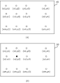
- FIG. 2 is a diagram showing an example of heat distribution information and reference heat distribution information.
- FIG. 2A shows an example of heat distribution information 40.
- the heat distribution information and the reference heat distribution information indicate temperature information for each point in the region indicated by two-dimensional coordinates. For example, when the temperature sensor 10 detects (sampling) n temperatures in the region at equal intervals on the horizontal axis and m temperatures at equal intervals on the vertical axis, the temperature information at the position of m ⁇ n acquired from the temperature sensor 10 By converting the positional relationship of the virtual region using the above, it is possible to generate heat distribution information having temperature information at the position of the white circle as shown in FIG. 2 (a). In FIG.
- thermography image For example, it is possible to generate heat distribution information that is visually easy to imagine when presented to a user by making an image in which a low temperature is strong in blue and a high temperature is strong in red, that is, a so-called thermography image.
- the heat distribution generation unit 220 performs interpolation processing using the temperature detection result around the region. Therefore, the heat distribution information 40 can be generated. Similarly, even at a position where the temperature sensor 10 has not detected (sampled) the temperature, the heat distribution generation unit 220 can generate the heat distribution information 40 by performing interpolation processing using the temperature detection result around the position.
- the heat distribution generation unit 220 may interpolate using the temperature information from the temperature sensor 10 around the position. By doing so, even if the temperature sensor 10 detects the temperature information at regular intervals, the heat distribution generation unit 220 can interpolate the temperature information during that period using the detection results of the surroundings. can.
- FIG. 2B shows an example of the reference heat distribution information 50.
- the temperature information is indicated by white circles for the points in the region indicated by the two-dimensional coordinates.
- it is shown as a black circle instead of a white circle as if the local temperature is set at the position of the coordinates (x2, y2).
- reference heat distribution information is generated so that the temperature in the region becomes the same with the set temperature when the user starts the operation of the air conditioner 20 as the initial value.
- the set temperature is set at the position of the coordinates (x2, y2).
- the reference heat distribution information is generated by interpolating around the set position, it can be generated so that the closer the user is to the set position, the closer the temperature distribution is to the set temperature.
- the reference heat distribution information may be generated by acquiring information such as the floor plan of the area and then changing the interpolation method.
- the reference heat distribution information is adjusted to be feasible.
- the blast control unit 250 inputs the heat distribution information from the heat distribution generation unit 220 and the reference heat distribution information from the reference heat distribution generation unit 240 so that the difference between the heat distribution information and the reference heat distribution information becomes small. Control the ventilation settings.
- the blast setting includes the direction of the blasted air, but may also include the temperature setting and the humidity setting of the air for blasting.
- the air conditioner 20 controls the air to be blown based on the air conditioner setting, and controls the louver (not shown) provided at the air outlet of the air conditioner 20 so that the wind direction can be changed up, down, left and right.
- the sum of the errors between the heat distribution information and the reference heat distribution information at a plurality of positions in the region is calculated, and control is performed until the error becomes smaller than a predetermined threshold value. Further, the position having the maximum error among the errors for each position is controlled in the direction of suppressing the error. If the calculation result of the error between the heat distribution information and the reference heat distribution information does not differ much from the previous calculation result, the control of the blower setting is stable, or the setting that the air conditioner 20 can control. It can be judged that the control is close to the limit.
- the entire region has the same temperature (for example, 28 ° C.) as shown in FIG. 2 (a), and the reference heat distribution is local only at the coordinate position (x2, y2) as shown in FIG. 2 (b). If there is reference heat distribution information at a set temperature (for example, 26 ° C), the wind direction of the air conditioner is adjusted so that the coordinate position (x2, y2) locally approaches 26 ° C.
- a set temperature for example, 26 ° C
- FIG. 3 is a diagram showing a transition of heat distribution information under the control of the blast control unit 250, in which order is FIG. 3 (a), FIG. 3 (b), and FIG. 3 (c) after the blast control unit 250 starts to control. ), And the transition of heat distribution information with FIG. 3 (d) is shown as an example.
- the heat distribution information before the blast control unit 250 operates has the same temperature in the entire region as shown in FIG. 2A (for example, 28 ° C.), and the user sets the local temperature at the coordinate position (x2, y2). (For example, 26 ° C.) is instructed, and it is assumed that the reference heat distribution information 50 as shown in FIG. 2 (b) is generated.
- the blower control unit 250 is 28 ° C. as a whole and the coordinate positions (x2, y2) are 26 ° C., which is a local temperature setting, so that the heat distribution information approaches the reference heat distribution information 50.
- the air conditioner controls the direction of the air blown for which the temperature is set so as to hit the coordinate position (x2, y2).
- the coordinate position (x2, y2) gradually approaches 26 ° C. as shown in FIG. 3A
- the coordinate position (x2, y2) gradually approaches 26 ° C. as shown in FIG. 3B, for example.
- the coordinate positions (x2, y1) gradually approach 26 ° C.
- the setting is updated so that the direction of the blast is closer to the coordinate position (x2, y3) than the initial setting.
- the difference between the heat distribution information 41d and the reference heat distribution information 50 can be reduced.
- the heat distribution information and the reference heat distribution information can be dealt with if the positional relationship and the temperature information at that position are known, so that it is not easy to visually grasp like a so-called thermographic image. It doesn't matter. Therefore, if there is no function to display to the user, the same effect can be obtained by using a table list of position information that shows the positional relationship with the surroundings and temperature information at that position as heat distribution information and reference heat distribution information. It is possible to respond to the above.
- the direction of the blast is adjusted so that the difference between the heat distribution information generated from the result of actually detecting the temperature information in the region and the reference heat distribution information set by the user becomes small. Therefore, it is possible to respond while detecting the influence in the fluctuating area.
- the air blower control unit 250 utilizes the second air outlet to be local. It becomes possible to expand the range that can correspond to the temperature setting. Furthermore, if the air conditioner can blow air with multiple types of temperature settings, the range that can be applied to local temperature settings can be further expanded by blowing air with different temperature settings to each air outlet. Will be possible.
- FIG. 4 is a block diagram schematically showing the configuration of the air conditioner 21 according to the second embodiment.
- the part different from the first embodiment is a part provided with a remote terminal 31 capable of communicating with the air conditioner 21 and displaying the heat distribution information acquired from the air conditioner 21, and the heat distribution information generated by communicating with the remote terminal 31.
- the transmission / reception unit 261 acquires the heat distribution information generated by the heat distribution generation unit 220 and transmits it to the remote terminal 31. Further, a signal including information on the set temperature in the region during operation of the air conditioner 21 from the remote terminal 31 is received.
- the remote terminal 31 acquires the heat distribution information transmitted from the transmission / reception unit 261 and displays it to the user. Further, the remote terminal 31 acquires the setting information in the area during operation of the air conditioner 21 from the user and transmits it to the transmission / reception unit 261.
- the remote terminal 31 is provided with a touch panel display unit to display the acquired heat distribution information, acquires the area to be set by the user by touch input, and obtains the temperature, humidity, wind strength, etc. of the touched area. By inquiring and asking the user to input, the setting information in the area specified by the user is acquired.
- the temperature setting in addition to the setting in absolute temperature, the relative temperature setting information indicating the information of the temperature setting relative to the current temperature may be used. The same applies to humidity and wind strength.
- the user activates the air conditioner 21 from the remote terminal 31.
- the air conditioner 21 acquires temperature information from the temperature sensor 10 after starting.
- the heat distribution generation unit 220 generates heat distribution information in the current region based on the acquired temperature information.
- the transmission / reception unit 261 transmits a signal including the generated heat distribution information to the remote terminal 31.
- the remote terminal 31 displays the heat distribution information acquired from the received signal on the display unit (not shown) of the remote terminal 31.
- the user selects the area to be set from the displayed heat distribution information.
- the remote terminal 31 displays a display indicating that the temperature, humidity, wind direction, air volume, etc. to be set are inquired for the area selected by the user.
- the user sets the temperature, humidity, wind direction, air volume, etc. to be set according to the display of the remote terminal 31.
- the remote terminal 31 transmits a signal including setting information such as the temperature, humidity, wind direction, and air volume to be set to the air conditioner 21 in association with the information in the selected area.
- the transmission / reception unit 261 receives a signal sent from the remote terminal 31 including the setting information associated with the selected area information, and the reference heat distribution generation unit 240 uses the setting information to reference heat. Generate distribution information.
- the blast control unit 250 performs blast control so that the difference between the heat distribution information and the reference heat distribution information from the heat distribution information and the reference heat distribution information becomes small.
- the heat distribution unit 261 may transmit the target heat distribution information.
- the user can grasp the current heat distribution. If the past heat distribution information for a plurality of times is transmitted and the heat distribution information is continuously displayed together with the generated time information, the user can confirm the temporal change of the heat distribution information.
- the reference heat distribution information generated by the reference heat distribution generation unit 240 based on the setting information may also be transmitted to the remote terminal 31 via the transmission / reception unit 261.
- the remote terminal 31 can also display the reference heat distribution information transmitted from the transmission / reception unit 261 to the user, and the user can grasp the current setting status. Furthermore, by converting the heat distribution information and the reference heat distribution information into an superimposed image and displaying it, it becomes possible for the user to easily grasp the target reference heat distribution by the current heat distribution and setting.
- the remote terminal 31 is not limited to the remote controller dedicated to the air conditioner, and the same effect can be obtained even with a smartphone, tablet, or PC on which an application corresponding to the above display and setting is installed. Needless to say.
- each setting information from a plurality of remote terminals 31 may be acquired.
- the reference heat distribution generation unit 240 integrates the respective setting information to generate the reference heat distribution.
- FIG. 5 is a block diagram schematically showing the configuration of the air conditioner 22 according to the third embodiment.
- the main difference from the above-described embodiment is the portion including the storage unit 270.
- the storage unit 270 stores the user position information in which the user information and the stay position of the user in the area are linked in advance.
- FIG. 6 is an example diagram showing a user's stay position in the area.
- FIG. 6A is a seat layout diagram 42 showing a certain coordinate position of a seat in the area
- FIG. 6B shows a table 60 in which the user and the stay position (seat) are associated with each other.
- the coordinate position indicating the seat position of the person with the user ID 50a is (x1, y1)
- the coordinate position indicating the seat position of the person with the user ID 50b is (x1, y2)
- the user ID is 50c.
- the coordinate position indicating the seat position of the person is (x1, y3)
- the coordinate position indicating the seat position of the person with the user ID of 50z is (xm, ym).
- the data associated with the user ID which is the information associated with each user, and the coordinate position information indicating the seat position of the user is stored in the storage unit 270.
- FIG. 5 shows that each user has a remote terminal 32.
- Each remote terminal 32 transmits including a user ID that identifies the user in use. Further, here, it is sufficient to specify the setting information such as the set temperature at the position where the user is located without selecting the position to be set in the area.
- the receiving unit 262 receives a signal including setting information and user ID information from each remote terminal 32, and outputs the signal to the setting information acquisition unit 232.
- the setting information acquisition unit 232 is based on the data obtained by associating the user ID information acquired together with the setting information acquired from the reception unit 262 with the coordinate position information indicating the seat position of the user ID stored in the storage unit 270.
- the coordinate position associated with the user ID of the user who transmitted the setting information acquired from the receiving unit 262 is set as the position where the setting information is to be set, and the position to be set and the setting information are supplied to the reference heat distribution generation unit 240.
- the remote terminal 32 even if the remote terminal 32 does not have a user interface for designating the setting position after specifying the setting position, it only transmits the setting information such as the temperature and humidity of the seated position. The same effect can be achieved with a simple application.
- the receiving unit 262 may transmit the heat distribution information and the generated reference heat distribution information to the respective remote terminals as the transmitting / receiving unit.
- the storage unit 270 stores the data associated with the user ID and the stay position (seat), and further stores the transmission history of what kind of settings each user has transmitted in the past. .. Then, the user can acquire the information toward the room provided with the air conditioner 23, and generate and reflect the reference heat distribution based on the transmission history in advance before the user enters the area. can. For example, the setting set in the past by the user who is trying to enter the area is compared with the current heat distribution information at the user's seat position, and if the difference is larger than a predetermined threshold value, the user enters the room.
- control is performed by reflecting it in the reference heat distribution before transmitting the setting, and if it is below a predetermined threshold value, it is not reflected in the reference heat distribution from the time the user enters the room until the setting is transmitted.
- the storage unit 270 has the same effect even if it is a setting history instead of a transmission history.
- FIG. 7 shows an example of data stored in the storage unit 270 according to the present embodiment as Table 61.
- information indicating the seat position of the user, the premises entry / exit information of the user, and the transmission history of what kind of setting the user last transmitted is stored in association with the user ID.
- the entry / exit information on the premises for example, if there is an entry / exit management system that opens and closes by user authentication at the entrance / exit of the building or floor where the air conditioner 23 is installed, that information is used. Alternatively, if there is a premises entry / exit management system that opens and closes by user authentication at the entrance / exit of the building premises where the room provided with the air conditioner 23 is provided, that information is utilized.
- FIG. 8 is a block diagram schematically showing the configuration of the air conditioning system according to the present embodiment.
- an air conditioning system including a plurality of air conditioners 23 and a centralized control device 70 communicably connected to the plurality of air conditioners 23 is shown.
- control unit is independent as the centralized control device 70, and the respective air conditioners are harmonized. This is realized by transmitting control information to each machine 23.
- the centralized control device 70 shown in FIG. 8 corresponds to the air conditioner 20 shown in FIG. In FIG. 8, three air conditioners 23a, an air conditioner 23b, and an air conditioner 23c are communicably connected to each other. This connection is not limited to a wired connection, and may be in a state where communication is possible wirelessly.
- the control information generation unit 710 reduces the difference between the heat distribution information and the reference heat distribution information from the heat distribution information from the heat distribution generation unit 220 and the reference heat distribution information from the reference heat distribution generation unit 240. It generates control information to be controlled for each air conditioner 23. Here, it is assumed that the control information generation unit 710 grasps the position information provided for each air conditioner 23.
- the communication unit 720 transmits the control information generated by the control information generation unit 710 to each air conditioner 23.
- control information may be transmitted for each air conditioner 23.
- a device ID may be assigned to each air conditioner 23 in advance, and control information may be transmitted together with the device ID.
- Each air conditioner 23 receives a transmission signal including control information from the centralized control device 70, and if the transmitted control information includes control information related to the own unit, the air conditioner 23 responds to the control information. Adjust the temperature and humidity, wind direction, and air volume of the air to be transmitted.
- the centralized control device 70 communicably connected to the air conditioners 23 provided with them can be used for heat distribution information and reference in the region.
- the entire region where the plurality of air conditioners 23 are provided is used. Even if there is, it can be effective.
- the communication unit 720 may be configured to receive information from the temperature sensor 10 communicably connected to each air conditioner 23 and send it to the temperature information acquisition unit 210. With such a method, the temperature information in the region can be acquired without the temperature sensor 10 to which the centralized control device 70 is directly connected so as to be able to communicate directly.
- the communication unit 720 may be configured to receive information from the remote terminal 30 communicably connected to each air conditioner 23 and send it to the setting information acquisition unit 230.
- the centralized control device 70 can acquire the setting information from the user in the area even if there is no remote terminal 30 directly connected to the centralized control device 70 so as to be able to communicate directly.
- the centralized control device 70 does not need to be provided in the corresponding area, and is not limited to the edge server in the premises but the Internet.
- the function can be executed by a cloud server or the like outside the premises that is communicably connected to each air conditioner 23 via the air conditioner 23.
- the centralized control device 70 is shown corresponding to the air conditioner 20 shown in FIG. 1, but is configured to correspond to the air conditioner 21 of FIG. 4 and the air conditioner 22 of FIG.
- the effects of each embodiment are achieved.
- the centralized control device 70 can execute its function on a computer server or the like.
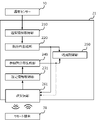
- FIG. 9 is a diagram showing the centralized control device 70 using a processor.
- the processor 711 is connected to a memory 712, a key input / output interface (hereinafter, I / F) 713, a data input / output I / F715, and a display output I / F714.
- I / F key input / output interface
- the processor 711 is hardware that operates when a program for executing the process of the present disclosure is executed using the memory 712.
- the key input / output I / F 713 is used when connected to a touch key device such as a keyboard or a remote terminal 30 to set a threshold value from the user.
- the data input / output I / F 715 is used when connected to the temperature sensor 10 to acquire temperature information. It is also used when acquiring information on entering and exiting the premises.
- the data input / output I / F 715 is connected to an external storage device and records user position information, previous setting information for each user, installation position information of the air conditioner 23, etc. by accessing the external storage device (not shown). It doesn't matter.
- the display output I / F 714 is used for displaying heat distribution information and the like.
Landscapes
- Engineering & Computer Science (AREA)
- Signal Processing (AREA)
- Physics & Mathematics (AREA)
- Chemical & Material Sciences (AREA)
- Combustion & Propulsion (AREA)
- Mechanical Engineering (AREA)
- General Engineering & Computer Science (AREA)
- Fuzzy Systems (AREA)
- Mathematical Physics (AREA)
- Fluid Mechanics (AREA)
- Air Conditioning Control Device (AREA)
Abstract
空気調和機、および複数の空気調和機を制御する空気調和システムにおいて領域内において例えば局所的に設定温度差を与える設定をした場合に、設定した位置とその周辺の温度状況を考慮して継続的に運転状態を制御することができる空気調和機を提供することを目的とするものであって、領域内の温度情報を検知した結果を取得する温度情報取得部(210)と温度情報から領域内の熱分布情報を生成する熱分布生成部(220)と領域内の参照熱分布情報を生成する参照熱分布生成部(240)と熱分布情報と参照熱分布情報との差が小さくなるように送風設定を制御する送風制御部(250)とを備える。
Description
本開示は、空気調和機およびこの空気調和機を備えた空気調和システムに関する。
近年、空気調和機、および複数の空気調和機を制御する空気調和システムにおいて、その空気調和機が設置された領域内における人の有無、および人数情報を人感センサーから得て、それらの情報に基づいて空気調和機の運転状態を制御する空気調和技術が提供されている。
例えば、特許文献1では、領域内を複数のエリアに分割して空気調和機の運転状態を制御する技術が開示されている。
上述した特許文献1では、領域内において例えば局所的に設定温度差を与える設定をした場合に、設定した位置とその周辺の温度状況を考慮して継続的に運転状態を制御することについて言及されていない。
本開示は、領域内において例えば局所的に設定温度差を与える設定をした場合に、設定した位置とその周辺の温度状況を考慮して継続的に運転状態を制御することができる空気調和機を提供することを目的とする。
本開示に係る情報処理装置は、領域内の温度情報を検知した結果を取得する温度情報取得部と、温度情報から領域内の熱分布情報を生成する熱分布生成部と、領域内の参照熱分布情報を生成する参照熱分布生成部と、熱分布情報と参照熱分布情報との差が小さくなるように送風設定を制御する送風制御部とを備えることを特徴とする。
本開示によれば、領域内の温度情報を検知した結果から領域内の熱分布情報を生成し、領域内の参照熱分布情報との差が小さくなるように運転状態を制御することで、領域内において例えば局所的に設定温度差を与える設定をした場合に、設定した位置とその周辺の温度状況を考慮して継続的に運転状態を制御することができる。
実施の形態1.
以下、図面を参照しながら実施の形態を説明する。以下の図面の記載において、同一又は類似の部分には、同一又は類似の符号を付している。但し、図面は模式的なものであり、各寸法の比率などは現実のものとは異なることに留意すべきである。したがって、具体的な寸法等は以下の説明を参酌して判断すべきものである。また、図面相互間においても互いの寸法の関係や比率が異なる部分が含まれていることは勿論である。
以下、図面を参照しながら実施の形態を説明する。以下の図面の記載において、同一又は類似の部分には、同一又は類似の符号を付している。但し、図面は模式的なものであり、各寸法の比率などは現実のものとは異なることに留意すべきである。したがって、具体的な寸法等は以下の説明を参酌して判断すべきものである。また、図面相互間においても互いの寸法の関係や比率が異なる部分が含まれていることは勿論である。
図1は、本実施の形態に係る空気調和機の構成を概略的に示すブロック図である。
本実施の形態に係る空気調和機20は、温度情報取得部210と熱分布生成部220と設定情報取得部230と参照熱分布生成部240と送風制御部250とを備える。また、空気調和機20は、温度センサー10とリモート端末30と通信可能に接続されている。図1では、温度センサー10を空気調和機20の外部に構成しているが空気調和機20が内蔵していても構わないし、複数の温度センサー10と接続する構成であっても構わない。また、温度センサー10と空気調和機20との間もリモート端末30と空気調和機20との間も、赤外線や5G通信など無線通信で接続されてもLANネットワークなどを介して接続されていても構わない。
温度センサー10は、領域内の温度情報を検知して、温度情報取得部210へ検知した領域内の温度情報を供給する。ここで領域とは、空気調和機20が設置され、空気調和機20によってその空間内の温度や湿度の制御が期待されている空間の領域を示す。例えばリビングルームに空気調和機20が設けられた場合は、リビングルームが領域となる。リビングルームとキッチンルームがオープンに繋がっていて、温度センサー10がキッチンルームの温度情報を検知可能に設けられている場合は、領域にキッチンルームを含んでも構わない。
温度情報取得部210は、温度センサー10から領域内の温度情報を取得する。
熱分布生成部220は、温度情報取得部210が取得した領域内の温度情報から領域内の熱分布情報を生成する。例えば、温度センサー10から領域内の検知対象位置を示す位置情報とその検知対象位置での検知した温度情報を元に、領域内空間を示す仮想領域における検知対象位置に変換し、その仮想領域内の位置に検知した温度情報でプロットしたものを熱分布情報として生成する。さらに、そのプロットしたものから他の仮想領域内の位置について周辺の検知した温度情報を用いて補間したものを熱分布情報としても構わない。
設定情報取得部230は、リモート端末30などから空気調和機20の運転中における領域内の設定情報を取得する。設定情報は、領域内における位置の設定温度を含む。また、設定情報は、領域内における位置の設定湿度、設定風量、直接風を避ける設定、及び消費電力量を抑えるエコモード設定などを含んでもよい。
参照熱分布生成部240は、設定情報取得部230が取得した領域内の設定温度情報から領域内の参照熱分布情報を生成する。
図2は、熱分布情報及び参照熱分布情報の例を示す図である。図2(a)は、熱分布情報40の例を示す。熱分布情報及び参照熱分布情報は、領域内を2次元座標で示した点に対してそれぞれ温度情報を示す。例えば温度センサー10が領域内を横軸に等間隔でn個、縦軸に等間隔でm個の温度検知(サンプリング)をするとした場合、温度センサー10から取得したm×nの位置の温度情報を用いて領域を仮想領域としたものの位置関係を変換することで、図2(a)のような白抜き丸の位置に温度情報を持つ熱分布情報を生成することができる。図2(a)では全ての位置において白抜き丸で示しているが、この白抜き丸の色を温度に基づいて変化させることで温度情報を表現する。例えば、低い温度は青色を強く高い温度は赤色を強くした画像、いわゆるサーモグラフィー画像のようにすることでユーザーへ提示した場合に視覚的に想像しやすい熱分布情報を生成することができる。
また、温度センサー10が領域内をm×nの位置全てで温度検知(サンプリング)した結果を取得できていない場合は、熱分布生成部220は、その周辺の温度検知結果を用いて補間処理することで熱分布情報40は生成できる。同様に、温度センサー10が温度検知(サンプリング)していない位置についても、熱分布生成部220は、その周辺の温度検知結果を用いて補間処理することで熱分布情報40は生成できる。
同様に、温度センサー10が直接検知できていない位置においても、熱分布生成部220は、その位置周辺における温度センサー10からの温度情報を用いて補間するものとしても構わない。このようにすることで、温度センサー10が一定間隔で温度情報を検知するようなものであっても、熱分布生成部220は、その間の温度情報は周辺の検知結果を用いて補間することができる。
図2(b)は、参照熱分布情報50の例を示す。ここでは、領域内を2次元座標で示した点に対してそれぞれ白抜き丸で温度情報を示している。図2(b)では座標(x2,y2)の位置に局所的な温度設定がされたものとして白抜き丸ではなく黒塗りの丸として図示している。例えばユーザーから特に局所的な設定がない場合は、ユーザーが空気調和機20の運転を起動したときの設定温度を初期値として領域内が同じ温度になるような参照熱分布情報を生成する。また、例えば、図2(b)のように座標(x2,y2)の位置でユーザーがある設定温度を設定した場合は、その座標(x2,y2)の位置で設定された設定温度とするような参照熱分布情報に更新して生成する。設定した位置の周辺について補間して参照熱分布情報を生成すれば、そのユーザーが設定した位置に近づけば近づくほど設定温度に近い温度分布を持つように生成できる。参照熱分布情報の生成については、領域の間取りなどの情報を取得した上で補間の仕方を変えるなどして生成してもよい。また、空気調和機の性能による局所的な温度設定の限度をふまえて、ユーザーから空気調和機の性能を超えた設定の要求があった場合は、実現可能な参照熱分布情報に調整する。
送風制御部250は、熱分布生成部220からの熱分布情報と参照熱分布生成部240からの参照熱分布情報とを入力し、熱分布情報と参照熱分布情報との差が小さくなるように送風設定を制御する。送風設定とは、送風する風の向きを含むものであるが、送風するための空気の温度設定及び湿度設定を含んでもよい。空気調和機20は、その送風設定に基づいて送風する空気の制御と、風向きを上下左右へ可変できるように空気調和機20の送風口に設けられたルーバー(図示せず)の制御を行う。
例えば、領域のうち複数の位置における熱分布情報と参照熱分布情報との誤差の総和を算出し、その誤差が所定の閾値よりも小さくなるまで制御を行う。また、位置毎の誤差のうち最大誤差となっている位置について、その誤差を抑える方向に制御を行う。熱分布情報と参照熱分布情報との誤差の算出結果が、前回の算出結果とあまり差がなくなってくれば、送風設定の制御が安定している、もしくは空気調和機20が制御できうる設定の限界に近い制御ができていると判断することができる。
例えば、熱分布情報について図2(a)のように領域全体が同じ温度(例えば摂氏28℃)であり、参照熱分布が図2(b)のように座標位置(x2,y2)のみ局所的な設定温度(例えば摂氏26℃)になった参照熱分布情報があれば、座標位置(x2,y2)が局所的に摂氏26℃に近づくように空気調和機の風向きなどを調整する。
図3は、送風制御部250の制御によって熱分布情報の遷移を示す図であって、送風制御部250が制御し始めてから順に、図3(a)、図3(b)、図3(c)、そして図3(d)と熱分布情報が遷移していることを例として図示している。
送風制御部250が動作する前の熱分布情報が図2(a)のような領域全体が同じ温度(例えば摂氏28℃)であり、ユーザーから座標位置(x2,y2)に局所的な温度設定(例えば摂氏26℃)が指示され、図2(b)のような参照熱分布情報50が生成されたとする。このとき、送風制御部250は、熱分布情報が参照熱分布情報50に近づくように、全体は摂氏28℃で、座標位置(x2、y2)は局所的な温度設定である摂氏26℃になるように、空気調和機が温度設定を行った空気の送風の向きが座標位置(x2,y2)に当たるように制御する。これにより、図3(a)のように徐々に座標位置(x2,y2)が摂氏26℃に近づき、例えば図3(b)のように座標位置(x2,y2)が摂氏26℃に近づくのに併せて、座標位置(x2,y1)も徐々に摂氏26℃に近づいたものとする。この場合、送風の向きを最初の設定よりも座標位置(x2,y3)寄りに設定を更新する。
その後、図3(c)のように座標位置(x1,y2)が摂氏26℃に近づくような熱分布情報41Cが生成された場合は、さらに送風の向きを座標位置(x3,y2)寄りに設定を更新する。
このようにして熱分布情報41dと参照熱分布情報50との差を小さくすることができる。なお、送風制御部250にとっては、熱分布情報及び参照熱分布情報は、位置関係とその位置での温度情報が分かれば対応できるため、いわゆるサーモグラフィー画像のような視覚的に把握しやすいものでなくても構わない。従って、ユーザーに表示する機能を持たない場合は、周囲との位置関係が分かる位置情報とその位置での温度情報のテーブルリストのようなものを熱分布情報及び参照熱分布情報としても同様の効果を奏する対応が可能である。
実際には領域内には背の高い家具、壁、またはパーティションなど様々なものが配置されていたりすることがあるので、空気調和機20が座標位置(x2,y2)に向けて狙い通りに送風の向きを変えても、背の高い家具やパーティションなどが送風の反射や遮断の要因となって、必ずしもユーザーが希望するような参照熱分布にならない場合がある。また、家であれば調理機、オフィスであればコンピューターなど熱源となるものもあり、さらに人やペットなど領域内で動くもので熱源となり得るものもある。窓から差し込む太陽光による影響も変動する。そのため、領域内の構造のみではなく、熱源温度の変動または熱源位置の変動によって、参照熱分布情報50に対応する空気調和機20による風向きの最適設定は、調整が継続的に必要な場合が生じる。このような場合、本発明では、実際に領域内の温度情報を検知した結果から生成する熱分布情報と、ユーザーが設定する参照熱分布情報との差が小さくなるように送風の向きを調整することで、変動する領域内の影響を検知しながら対応することができる。
また、空気調和機20が通常の送風口とは別に局所的な送風を実現する第2の送風口を備えることで、送風制御部250は、その第2の送風口を活用して局所的な温度設定に対応できる幅を広げることが可能になる。さらに、複数種類の温度設定をした空気を送風できる空気調和機であれば、それぞれの送風口に異なる温度設定された空気を送風することで、局所的な温度設定に対応できる幅をさらに広げることが可能になる。
実施の形態2.
図4は、実施の形態2に係る空気調和機21の構成を概略的に示すブロック図である。実施の形態1と異なる部分は、空気調和機21と通信を行い空気調和機21から取得した熱分布情報を表示可能なリモート端末31を備える部分、リモート端末31と通信を行い生成した熱分布情報を送信する送受信部261を備える部分、そして送受信部261を介して空気調和機21の運転中における領域内の設定情報を取得する設定情報取得部231を備える部分である。
図4は、実施の形態2に係る空気調和機21の構成を概略的に示すブロック図である。実施の形態1と異なる部分は、空気調和機21と通信を行い空気調和機21から取得した熱分布情報を表示可能なリモート端末31を備える部分、リモート端末31と通信を行い生成した熱分布情報を送信する送受信部261を備える部分、そして送受信部261を介して空気調和機21の運転中における領域内の設定情報を取得する設定情報取得部231を備える部分である。
送受信部261は、熱分布生成部220が生成する熱分布情報を取得してリモート端末31へ送信する。また、リモート端末31からの空気調和機21の運転中における領域内の設定温度の情報を含む信号を受信する。
リモート端末31は、送受信部261から送信された熱分布情報を取得し、ユーザーに表示する。また、リモート端末31は、ユーザーからの空気調和機21の運転中における領域内の設定情報を取得して、送受信部261へ送信する。例えばリモート端末31は、タッチパネル表示部を備えて取得した熱分布情報を表示し、ユーザーから設定したい領域をタッチ入力により取得してそのタッチされた領域の温度、湿度、または風の強さなどを問合せてユーザーに入力してもらうことで、ユーザーが指定する領域内の設定情報を取得する。温度設定については、絶対温度での設定のほか、現在の温度に対して相対的な温度設定の情報を示す相対温度設定情報でも構わない。湿度及び風の強さについても同様である。
ここで、本実施の形態における空気調和機21について、動作の流れの例を説明する。ユーザーがリモート端末31から空気調和機21を起動させる。
次に、空気調和機21は、起動後に温度センサー10から温度情報を取得する。
次に、熱分布生成部220は、取得した温度情報に基づいて現状の領域における熱分布情報を生成する。
次に、送受信部261は、生成した熱分布情報を含む信号をリモート端末31へ送信する。
次に、リモート端末31は、受信した信号から取得した熱分布情報をリモート端末31の表示部(図示せず)に表示する。
次に、ユーザーは、表示された熱分布情報から、設定したい領域を選択する。
次に、リモート端末31は、ユーザーが選択した領域に対して、設定する温度、湿度、風向き、そして風量などを問合せることを示す表示を行なう。
次に、ユーザーは、リモート端末31の表示に応じて設定する温度、湿度、風向き、そして風量などを設定する。
次に、リモート端末31は、選択された領域の情報に対応付けて、設定する温度、湿度、風向き、そして風量などの設定情報を含む信号を空気調和機21へ送信する。
次に、送受信部261は、リモート端末31から送られた、選択された領域情報に対応付けた設定情報を含む信号を受信し、参照熱分布生成部240は、その設定情報を用いて参照熱分布情報を生成する。
そして、送風制御部250は、熱分布情報と参照熱分布情報とから熱分布情報が参照熱分布情報との差が小さくなるように送風制御を行う。
また、上では空気調和機21の動作起動時に自動的に熱分布情報を送信する手順で説明しているが、ユーザーが現状の熱分布情報を要求することを示す送信信号をリモート端末31から送信し、空気調和機21の送受信部261が受信してから、対象の熱分布情報を送受信部261から送信しても構わない。
このように、ユーザーに現状の熱分布情報を表示することで、ユーザーは現状の熱分布を把握することが可能となる。なお、複数回分の過去の熱分布情報を送信し、熱分布情報を生成した時間情報と共に連続して表示すれば、熱分布情報の時間的変化をユーザーが確認することができる。
また、設定情報に基づいて参照熱分布生成部240が生成した参照熱分布情報についても、送受信部261を介してリモート端末31へ送信しても構わない。この場合、リモート端末31は、送受信部261から送信された参照熱分布情報についてもユーザーに表示することが可能となり、現状の設定状況をユーザーが把握することが可能になる。さらに、熱分布情報と参照熱分布情報とを重畳した画像に変換して表示することで、現状の熱分布と設定によって目標となる参照熱分布をユーザーが把握しやすくすることが可能になる。
なお、リモート端末31は、空気調和機専用のリモートコントローラに限らず、上記の表示および設定に対応するアプリケーションをインストールされたスマートホン、タブレット、またはPCなどであっても同様の効果を奏することは言うまでもない。
また、複数のリモート端末31からのそれぞれの設定情報を取得しても構わない。その場合は、参照熱分布生成部240は、それぞれの設定情報を統合して参照熱分布を生成する。同じ位置で異なる設定を受信した場合は、先に設定情報を取得した側の設定を優先する方法、異なる設定を受け付けたことをリモート端末31へ送信した後、改めて同じ位置で異なる設定を受信した場合は後で受信した設定を優先する方法、同じ位置で異なる設定の中間設定をした上での参照熱分布情報を表示する方法などで対応する。
実施の形態3.
図5は、実施の形態3に係る空気調和機22の構成を概略的に示すブロック図である。上述の実施の形態と主に異なる部分は、記憶部270を備える部分である。
図5は、実施の形態3に係る空気調和機22の構成を概略的に示すブロック図である。上述の実施の形態と主に異なる部分は、記憶部270を備える部分である。
記憶部270は、予めユーザー情報と領域内における当該ユーザーの滞在位置とを紐づけたユーザー位置情報を記憶する。
図6は、領域内におけるユーザーの滞在位置を示す例図である。図6(a)は、領域内の座席のある座標位置を示す座席レイアウト図42であり、図6(b)は、ユーザーと滞在位置(座席)とを紐づけた表60を示す。図6(b)ではユーザーIDが50aの人の座席位置を示す座標位置は(x1,y1)、ユーザーIDが50bの人の座席位置を示す座標位置は(x1,y2)、ユーザーIDが50cの人の座席位置を示す座標位置は(x1,y3)、そしてユーザーIDが50zの人の座席位置を示す座標位置は(xm,ym)であることを示している。
例えば職場のオフィスにおいて決められた座席で仕事をする状況であれば、誰がどこの座席を使うかはあらかじめ決められている場合がある。その場合はそれぞれのユーザーに紐づけられた情報であるユーザーIDとそのユーザーの座席位置を示す座標位置情報とを紐づけたデータを記憶部270に記憶しておく。
図5では、ユーザーがそれぞれリモート端末32を所持しているものとして図示している。それぞれのリモート端末32は、使用しているユーザーを特定するユーザーIDを含めて送信する。また、ここでは領域内の設定したい位置を選択せずに自分の所在位置での設定温度などの設定情報を指定するだけで構わない。
受信部262は、それぞれのリモート端末32から設定情報とユーザーIDの情報とを含む信号を受信し、設定情報取得部232へ出力する。
設定情報取得部232は、受信部262から取得した設定情報と共に取得したユーザーIDの情報と、記憶部270が記憶しているユーザーIDの座席位置を示す座標位置情報を紐づけたデータとから、受信部262から取得した設定情報を送信したユーザーのユーザーIDに紐づけられた座標位置をその設定情報を設定したい位置として、参照熱分布生成部240へ設定したい位置とその設定情報について供給する。
このように、本実施の形態では、リモート端末32が設定位置を指定してから設定情報を指定するユーザーインターフェイスがなくとも、自分の在席位置の温度や湿度などの設定情報を送信するだけの簡易なアプリケーションでも同様の効果を奏することができる。
また実施の形態2のように受信部262は、送受信部として熱分布情報や生成した参照熱分布情報をそれぞれのリモート端末へ送信しても構わない。
また記憶部270は、ユーザーIDと滞在位置(座席)とを紐づけたデータを記憶していたが、さらにそれぞれのユーザーが過去にどのような設定を送信したかの送信履歴を記憶しておく。そして、そのユーザーが空気調和機23の設けられた部屋に向かっている情報を取得して、そのユーザーが当該領域に入る前に前もって送信履歴に基づいて参照熱分布を生成して反映させることができる。例えば当該領域に入ろうとしているユーザーが過去に設定している設定と、そのユーザーの座席位置における現状の熱分布情報とを比較して、その差が所定の閾値より大きい場合はそのユーザーが入室してから設定を送信する前から参照熱分布に反映させて制御を行ない、所定の閾値以下であればそのユーザーが入室してから設定を送信するまで参照熱分布に反映させない。ここで、記憶部270は、送信履歴ではなく設定履歴であっても同様の効果を奏する。
図7は、本実施の形態にかかる記憶部270が記憶するデータの例を表61として示す。図7では、ユーザーIDに紐づけて当該ユーザーの座席位置、当該ユーザーの構内入退出情報、そして当該ユーザーが前回どのような設定を送信したかの送信履歴を示す情報を記憶する。
構内入退出情報は、例えば、空気調和機23の設けられた部屋のある建物またはフロアの出入り口にユーザー認証で開閉するような入退室管理システムがあれば、その情報を活用する。または、空気調和機23の設けられた部屋のある建物構内の出入り口にユーザー認証で開閉する構内入退出管理システムがあればその情報を活用する。
これにより、当該ユーザーの嗜好に合わせた設定を当該ユーザーが空気調和機23の設けられた部屋に入る前から設定することが可能になる。
実施の形態4.
図8は、本実施の形態に係る空気調和システムの構成を概略的に示すブロック図である。本実施の形態では、複数の空気調和機23と、その複数の空気調和機23と通信可能に接続された集中制御装置70とを備える空気調和システムを示す。
図8は、本実施の形態に係る空気調和システムの構成を概略的に示すブロック図である。本実施の形態では、複数の空気調和機23と、その複数の空気調和機23と通信可能に接続された集中制御装置70とを備える空気調和システムを示す。
上述の実施の形態では、空気調和機内に制御部を備えた構成を例として説明していたが、本実施の形態では制御部に相当するものが集中制御装置70として独立し、それぞれの空気調和機23ごとへ制御情報を送信することで実現する。
図8に示す集中制御装置70は、図1に示す空気調和機20に対応して示す。図8では3台の空気調和機23a、空気調和機23b、そして空気調和機23cと通信可能に接続されている。この接続は有線接続に限らず、無線で通信可能に接続されている状態であっても構わない。
制御情報生成部710は、熱分布生成部220からの熱分布情報と参照熱分布生成部240からの参照熱分布情報とから、熱分布情報と参照熱分布情報との差が小さくなるように、それぞれの空気調和機23に対して制御する制御情報を生成する。ここで制御情報生成部710は、それぞれの空気調和機23が設けられた位置情報を把握しているものとする。
通信部720は、制御情報生成部710が生成した制御情報をそれぞれの空気調和機23へ送信する。この場合、それぞれの空気調和機23ごとに制御情報を送信するとしても構わない。また、それぞれの空気調和機23ごとに予め機器IDを割り当てて、機器IDと共に制御情報を送信するとしても構わない。
それぞれの空気調和機23は、集中制御装置70からの制御情報を含む送信信号を受信し、送られてきた制御情報に自機が関連する制御情報を含んでいる場合は、その制御情報に応じて送信する空気の温度及び湿度、風向き、そして風量を調整して送風する。
このように、複数の空気調和機23を設けた領域内であっても、それらが設けられた空気調和機23と通信可能に接続された集中制御装置70が、領域内の熱分布情報および参照熱分布情報を生成し、熱分布情報と参照熱分布情報との差が小さくなるように、それぞれの空気調和機23に対して制御することで、複数の空気調和機23を設けた領域全体であっても効果を奏することができる。
また、通信部720は、それぞれの空気調和機23と通信可能に接続された温度センサー10からの情報を受信して、温度情報取得部210へ送る構成としても構わない。このような方法であれば集中制御装置70が直接的に通信可能に接続された温度センサー10がなくても領域内の温度情報を取得することができる。
さらに、通信部720は、それぞれの空気調和機23と通信可能に接続されたリモート端末30からの情報を受信して、設定情報取得部230へ送る構成としても構わない。このような方法であれば集中制御装置70が直接的に通信可能に接続されたリモート端末30がなくても領域内のユーザーからの設定情報を取得することができる。
このように集中制御装置70に直接的に温度センサー10及びリモート端末30と接続しない状況であれば、集中制御装置70は該当する領域内に設ける必要もなく、構内のエッジサーバに限らず、インターネット経由でそれぞれの空気調和機23と通信可能に接続された構外のクラウドサーバなどでその機能を実行することができる。
図8では、集中制御装置70は、図1に示す空気調和機20に対応して示していたが、図4の空気調和機21および図5の空気調和機22に対応したものに構成しても、それぞれの実施の形態の効果を奏することは言うまでもない。
集中制御装置70は、コンピューターサーバなどでその機能を実行することができる。
図9は、集中制御装置70についてプロセッサを用いて示した図である。プロセッサ711は、メモリ712、キー入出力インターフェース(以下、I/F)713、データ入出力I/F715、及び表示出力I/F714と接続されている。
プロセッサ711は、メモリ712を用いて、本開示の処理を実行するためのプログラムを実行するときに動作するハードウェアである。キー入出力I/F713は、キーボードやリモート端末30などタッチキーデバイスなどと接続されて、ユーザーからの閾値を設定するときに用いられる。データ入出力I/F715は、温度センサー10と接続されて温度情報を取得するときに用いられる。また、構内入退出情報を取得するときにも用いられる。
データ入出力I/F715は、外部記憶装置と接続されてユーザー位置情報、ユーザーごとの前回設定情報、空気調和機23の設置位置情報などを外部記憶装置(図示せず)にアクセスして記録しても構わない。表示出力I/F714は、熱分布情報を表示するなどに用いられる。
このようなプロセッサを用いた集中制御装置70であっても、上述の方法を実行するプログラムがあれば、それを実行することで効果を奏する。
10 温度センサー、20 空気調和機、30 リモート端末、210 温度情報取得部、220 熱分布生成部、230 設定情報取得部、240 参照熱分布生成部、250 送風制御部
Claims (9)
- 領域内の温度情報を検知した結果を取得する温度情報取得部と、
前記温度情報から前記領域内の熱分布情報を生成する熱分布生成部と、
前記領域内の参照熱分布情報を生成する参照熱分布生成部と、
前記熱分布情報と前記参照熱分布情報との差が小さくなるように送風設定を制御する送風制御部と、
を備える空気調和機。 - 前記送風制御部は、前記送風設定の制御に伴う前記熱分布情報と前記参照熱分布情報との差の時間変化を用いて前記送風設定を調整する
ことを特徴とする請求項1に記載の空気調和機。 - 前記領域内における位置の設定情報を取得する設定情報取得部を備え、
前記設定情報は、温度設定情報または相対温度設定情報を含み、
前記参照熱分布生成部は、前記設定情報取得部が取得した位置ごとの前記温度設定情報または前記相対温度設定情報に基づき前記参照熱分布情報を生成する
ことを特徴とする請求項1または請求項2に記載の空気調和機。 - 前記設定情報は、風量設定情報を含み、
前記送風制御部は、前記設定情報取得部が取得した位置ごとの前記風量設定情報に対応して前記送風設定を制御する
ことを特徴とする請求項3に記載の空気調和機。 - 前記熱分布生成部が生成した前記領域内の前記熱分布情報を送信し、前記領域内のうち何れかの位置を指定する位置情報及び指定した位置での前記設定情報を含むユーザー設定情報を受信する送受信部をさらに備え、
前記設定情報取得部は、前記送受信部が受信した前記位置情報に対応する前記設定情報を取得する
ことを特徴とする請求項3または請求項4に記載の空気調和機。 - 前記送受信部は、複数の前記ユーザー設定情報を受信し、
前記設定情報取得部は、前記送受信部が受信したそれぞれの前記位置情報に対応する前記設定情報を取得する
ことを特徴とする請求項5に記載の空気調和機。 - 予めユーザーに割り当てたユーザー情報と前記領域内における当該ユーザーの滞在位置とを紐づけたユーザー位置情報を記憶する記憶部と、
前記ユーザー情報及び当該ユーザーが指定する前記設定情報を含む第2のユーザー設定情報を受信する受信部とを備え、
前記設定情報取得部は、前記受信部が受信した前記第2のユーザー設定情報に含まれる前記ユーザー情報と前記ユーザー位置情報とから前記領域内の設定位置を推定し、当該当該第2のユーザー設定情報に含まれる前記設定情報を前記設定位置と対応付けて取得する
ことを特徴とする請求項3または請求項4に記載の空気調和機。 - 前記領域を含む敷地における前記ユーザー情報ごとの入退出情報を示す敷地入退出情報を取得する入退出情報取得部を備え、
前記記憶部は、前記ユーザー情報と当該ユーザーごとの前記設定情報の送信履歴を記憶し、
前記参照熱分布生成部は、前記敷地入退出情報から前記領域内にこれから侵入するまたは退出した前記ユーザーを特定し、特定した当該ユーザーごとの前記送信履歴を用いて前記参照熱分布情報を生成する
ことを特徴とする請求項7に記載の空気調和機。 - 制御情報を取得し、取得した前記制御情報に基づき送風設定を制御する複数の空気調和機と、
前記複数の空気調和機が設置された領域内の温度情報を検知した結果を取得する温度情報取得部と、
前記温度情報から前記領域内の熱分布情報を生成する熱分布生成部と、
前記領域内の参照熱分布情報を生成する参照熱分布生成部と、
前記熱分布情報と前記参照熱分布情報との差が小さくなるようにそれぞれの前記空気調和機を制御する前記制御情報を生成する制御情報生成部と、
前記制御情報をそれぞれの前記空気調和機へ送信する送信部と
を備える空気調和システム。
Priority Applications (4)
| Application Number | Priority Date | Filing Date | Title |
|---|---|---|---|
| US18/024,279 US20230324068A1 (en) | 2020-09-24 | 2020-09-24 | Air conditioner and air conditioning system |
| EP20955209.0A EP4220029A4 (en) | 2020-09-24 | 2020-09-24 | AIR CONDITIONING AND CLIMATE CONTROL SYSTEM |
| PCT/JP2020/036109 WO2022064615A1 (ja) | 2020-09-24 | 2020-09-24 | 空気調和機および空気調和システム |
| JP2022551507A JPWO2022064615A5 (ja) | 2020-09-24 | 空気調和機、空気調和システム、および制御方法 |
Applications Claiming Priority (1)
| Application Number | Priority Date | Filing Date | Title |
|---|---|---|---|
| PCT/JP2020/036109 WO2022064615A1 (ja) | 2020-09-24 | 2020-09-24 | 空気調和機および空気調和システム |
Publications (1)
| Publication Number | Publication Date |
|---|---|
| WO2022064615A1 true WO2022064615A1 (ja) | 2022-03-31 |
Family
ID=80844781
Family Applications (1)
| Application Number | Title | Priority Date | Filing Date |
|---|---|---|---|
| PCT/JP2020/036109 WO2022064615A1 (ja) | 2020-09-24 | 2020-09-24 | 空気調和機および空気調和システム |
Country Status (3)
| Country | Link |
|---|---|
| US (1) | US20230324068A1 (ja) |
| EP (1) | EP4220029A4 (ja) |
| WO (1) | WO2022064615A1 (ja) |
Citations (4)
| Publication number | Priority date | Publication date | Assignee | Title |
|---|---|---|---|---|
| JP2011094965A (ja) | 2007-06-13 | 2011-05-12 | Mitsubishi Electric Corp | 空気調和機およびこの空気調和機を備えた空気調和システム |
| WO2019026098A1 (ja) * | 2017-07-31 | 2019-02-07 | 三菱電機株式会社 | 空気調和システム及びゾーン空調制御方法 |
| WO2019224916A1 (ja) * | 2018-05-22 | 2019-11-28 | 三菱電機株式会社 | 空気調和装置およびこれを有する倉庫 |
| JP2020148385A (ja) * | 2019-03-13 | 2020-09-17 | ダイキン工業株式会社 | 空調制御システム、及び、空調制御方法 |
Family Cites Families (2)
| Publication number | Priority date | Publication date | Assignee | Title |
|---|---|---|---|---|
| JP2019027603A (ja) * | 2017-07-25 | 2019-02-21 | 三菱重工サーマルシステムズ株式会社 | 空調制御装置、空調システム、空調制御方法、及びプログラム |
| EP3708917B1 (en) * | 2017-11-06 | 2024-04-17 | Mitsubishi Electric Corporation | Operation terminal, program, and air-conditioning system |
-
2020
- 2020-09-24 EP EP20955209.0A patent/EP4220029A4/en active Pending
- 2020-09-24 US US18/024,279 patent/US20230324068A1/en active Pending
- 2020-09-24 WO PCT/JP2020/036109 patent/WO2022064615A1/ja unknown
Patent Citations (4)
| Publication number | Priority date | Publication date | Assignee | Title |
|---|---|---|---|---|
| JP2011094965A (ja) | 2007-06-13 | 2011-05-12 | Mitsubishi Electric Corp | 空気調和機およびこの空気調和機を備えた空気調和システム |
| WO2019026098A1 (ja) * | 2017-07-31 | 2019-02-07 | 三菱電機株式会社 | 空気調和システム及びゾーン空調制御方法 |
| WO2019224916A1 (ja) * | 2018-05-22 | 2019-11-28 | 三菱電機株式会社 | 空気調和装置およびこれを有する倉庫 |
| JP2020148385A (ja) * | 2019-03-13 | 2020-09-17 | ダイキン工業株式会社 | 空調制御システム、及び、空調制御方法 |
Non-Patent Citations (1)
| Title |
|---|
| See also references of EP4220029A4 |
Also Published As
| Publication number | Publication date |
|---|---|
| JPWO2022064615A1 (ja) | 2022-03-31 |
| EP4220029A1 (en) | 2023-08-02 |
| EP4220029A4 (en) | 2024-04-03 |
| US20230324068A1 (en) | 2023-10-12 |
Similar Documents
| Publication | Publication Date | Title |
|---|---|---|
| CN110300874B (zh) | 环境控制系统和环境控制方法 | |
| US10359747B2 (en) | Controlling device, controlling system and controlling method for indoor apparatus | |
| US10951750B2 (en) | Networked thermostat control for ductless HVAC | |
| JP6046579B2 (ja) | 空気調和機 | |
| CN105446162A (zh) | 一种智能家居系统以及机器人的智能家居控制方法 | |
| US20200232671A1 (en) | Device control system | |
| KR102121785B1 (ko) | 인공지능을 이용하여 지시된 위치로 풍향을 제어하는 에어컨 및 이를 제어하는 방법 | |
| JP6282926B2 (ja) | 制御方法及び通信装置 | |
| US11913663B2 (en) | Air-conditioning control device and air-conditioning control system | |
| WO2016157675A1 (ja) | 制御システム、制御方法及び制御プログラム | |
| KR20120039359A (ko) | 스마트폰과 센서를 이용한 인공지능 디지털기기 제어시스템 | |
| WO2017183083A1 (ja) | 空気調和システム | |
| JP2012172910A (ja) | 室内環境調整用機器の操作システム | |
| US11249449B2 (en) | Operation terminal, non-transitory computer-readable medium and air-conditioning system | |
| JP6790249B2 (ja) | 空調装置、空調システム、空調方法及びプログラム | |
| EP2696146B1 (en) | Air conditioning system | |
| KR102206461B1 (ko) | 공기조화기 시스템 및 그 동작방법 | |
| WO2022064615A1 (ja) | 空気調和機および空気調和システム | |
| CN112696785A (zh) | 空调器控制方法、控制系统和空调器 | |
| KR20140136768A (ko) | 공기조화기 시스템 및 그 동작방법 | |
| KR20170090668A (ko) | 공기조화기 및 그 제어방법 | |
| WO2018211592A1 (ja) | 空気調和システム | |
| JPWO2020235100A1 (ja) | 端末装置および温度制御システム | |
| JPH02133740A (ja) | 空気調和機の制御装置 | |
| WO2021234770A1 (ja) | 制御システム、設備機器システム及び設備機器の制御方法 |
Legal Events
| Date | Code | Title | Description |
|---|---|---|---|
| 121 | Ep: the epo has been informed by wipo that ep was designated in this application |
Ref document number: 20955209 Country of ref document: EP Kind code of ref document: A1 |
|
| ENP | Entry into the national phase |
Ref document number: 2022551507 Country of ref document: JP Kind code of ref document: A |
|
| NENP | Non-entry into the national phase |
Ref country code: DE |
|
| ENP | Entry into the national phase |
Ref document number: 2020955209 Country of ref document: EP Effective date: 20230424 |