WO2022064570A1 - モデル生成プログラム、モデル生成方法及びモデル生成装置 - Google Patents
モデル生成プログラム、モデル生成方法及びモデル生成装置 Download PDFInfo
- Publication number
- WO2022064570A1 WO2022064570A1 PCT/JP2020/035841 JP2020035841W WO2022064570A1 WO 2022064570 A1 WO2022064570 A1 WO 2022064570A1 JP 2020035841 W JP2020035841 W JP 2020035841W WO 2022064570 A1 WO2022064570 A1 WO 2022064570A1
- Authority
- WO
- WIPO (PCT)
- Prior art keywords
- machine learning
- data
- model
- learning model
- training data
- Prior art date
- Legal status (The legal status is an assumption and is not a legal conclusion. Google has not performed a legal analysis and makes no representation as to the accuracy of the status listed.)
- Ceased
Links
Images


Classifications
-
- G—PHYSICS
- G06—COMPUTING OR CALCULATING; COUNTING
- G06N—COMPUTING ARRANGEMENTS BASED ON SPECIFIC COMPUTATIONAL MODELS
- G06N20/00—Machine learning
-
- G—PHYSICS
- G06—COMPUTING OR CALCULATING; COUNTING
- G06N—COMPUTING ARRANGEMENTS BASED ON SPECIFIC COMPUTATIONAL MODELS
- G06N3/00—Computing arrangements based on biological models
- G06N3/02—Neural networks
- G06N3/08—Learning methods
- G06N3/082—Learning methods modifying the architecture, e.g. adding, deleting or silencing nodes or connections
Definitions
- the present invention relates to a model generation technique using training data.
- system Since the machine learning model determines and classifies according to the training data trained at the time of system development, the accuracy of the machine learning model deteriorates if the tendency of the input data changes during the system operation.
- FIG. 21 is a diagram for explaining the deterioration of the machine learning model due to the change in the tendency of the input data.
- the machine learning model described here is a model that classifies the input data into one of the first class, the second class, and the third class, and is pre-trained based on the training data before the system operation. do.
- distribution 1A shows the distribution of input data at the initial stage of system operation.
- Distribution 1B shows the distribution of the input data at the time when T1 time has elapsed from the initial stage of system operation.
- Distribution 1C shows the distribution of the input data at the time when T2 hours have elapsed from the initial stage of system operation. It is assumed that the tendency (feature amount, etc.) of the input data changes with the passage of time. For example, if the input data is an image, the tendency of the input data changes depending on the season and the time zone even if the image is taken of the same subject.
- the determination boundary 3 indicates the boundary between the model application areas 3a to 3c.
- the model application area 3a is an area in which training data belonging to the first class is distributed.
- the model application area 3b is an area in which training data belonging to the second class is distributed.
- the model application area 3c is an area in which training data belonging to the third class is distributed.
- the asterisk is input data that belongs to the first class, and it is correct that it is classified into the model application area 3a when it is input to the machine learning model.
- the triangle marks are input data belonging to the second class, and it is correct that they are classified into the model application area 3b when they are input to the machine learning model.
- the circles are input data belonging to the third class, and it is correct that they are classified into the model application area 3c when they are input to the machine learning model.
- distribution 1A all input data is distributed in the normal model application area. That is, the input data of the star mark is located in the model application area 3a, the input data of the triangle mark is located in the model application area 3b, and the input data of the circle mark is located in the model application area 3c.
- T 2 statistic Hotelling's T-square
- the data group of the input data and the normal data ( training data) is analyzed by the principal component, and the T2 statistic of the input data is calculated.
- the T 2 statistic is the sum of the squares of the distances from the origin of each standardized principal component to the data.
- the accuracy deterioration of the machine learning model is detected based on the change in the distribution of the T 2 statistic of the input data group.
- the T 2 statistic of the input data group corresponds to the percentage of outlier data.
- the above-mentioned conventional technique has a problem that it cannot detect a change in the distribution of data that may cause a deterioration in the accuracy of the machine learning model.
- the model generator causes the computer to perform a process of acquiring the result output from the first machine learning model in response to the input of the first plurality of data to the first machine learning model. ..
- the model generation program causes a computer to execute a process of selecting a second plurality of data from the first plurality of data based on the result.
- the model generation program takes a second plurality of data as inputs, and executes machine learning with some of the parameters included in the first machine learning model fixed, so that the second machine can be executed. Let the computer perform the process of generating the learning model.
- FIG. 1 is a diagram for explaining a reference technique.
- FIG. 2 is a diagram for explaining a mechanism for detecting a deterioration in accuracy of a machine learning model to be monitored.
- FIG. 3 is a diagram (1) for explaining the processing of the reference technique.
- FIG. 4 is a diagram (2) for explaining the processing of the reference technique.
- FIG. 5 is a diagram for explaining a problem of the reference technique.
- FIG. 6 is a diagram for explaining the processing of the model generator according to the present embodiment.
- FIG. 7 is a functional block diagram showing the configuration of the model generator according to the present embodiment.
- FIG. 8 is a diagram showing an example of the data structure of the training data set.
- FIG. 9 is a diagram showing an example of training data.
- FIG. 1 is a diagram for explaining a reference technique.
- FIG. 2 is a diagram for explaining a mechanism for detecting a deterioration in accuracy of a machine learning model to be monitored.
- FIG. 3 is a diagram (1) for explaining
- FIG. 10 is a diagram for explaining an example of a machine learning model.
- FIG. 11 is a diagram showing an example of the data structure of the inspector table.
- FIG. 12 is a diagram showing an example of the data structure of the training data table.
- FIG. 13 is a diagram showing an example of the data structure of the operation data table.
- FIG. 14 is a diagram showing an example of the classification result of each inspector.
- FIG. 15 is a diagram for explaining the processing of the detection unit.
- FIG. 16 is a flowchart (1) showing a processing procedure of the model generator according to the present embodiment.
- FIG. 17 is a flowchart showing a processing procedure of machine learning processing.
- FIG. 18 is a flowchart (2) showing a processing procedure of the model generator according to the present embodiment.
- FIG. 19 is a diagram for explaining the effect of the model generator according to the present embodiment.
- FIG. 20 is a diagram showing an example of a hardware configuration of a computer that realizes the same functions as the model generator according to the present embodiment.
- FIG. 21 is a diagram for explaining the deterioration of the machine learning model due to the change in the tendency of the input data.
- the reference technique for detecting the deterioration of the accuracy of the machine learning model will be described.
- the accuracy deterioration of the machine learning model is detected by using a plurality of monitors that narrow the model application area under different conditions.
- the monitor will be referred to as an "inspector”.
- FIG. 1 is a diagram for explaining a reference technique.
- the machine learning model 10 is a machine learning model in which machine learning is executed using training data.
- the training data is used when performing machine learning for the parameters of the machine learning model 10, and the correct answer label is associated with the training data.
- the machine learning model 10 is verified using the verification data.
- the inspectors 11A, 11B, and 11C have different model application areas under different conditions and have different decision boundaries. Since the inspectors 11A to 11C have different determination boundaries, the output results may differ even if the same input data is input. In the reference technique, the accuracy deterioration of the machine learning model 10 is detected based on the difference in the output results of the inspectors 11A to 11C.
- inspectors 11A to 11C are shown, but accuracy deterioration may be detected by using another inspector.
- DNN Deep Neural Network
- the inspector 11A be a machine learning model in which machine learning is executed using the same training data as the machine learning model 10.
- FIG. 2 is a diagram for explaining a mechanism for detecting a deterioration in accuracy of a machine learning model to be monitored.
- the inspectors 11A and 11B will be used for explanation.
- the decision boundary of the inspector 11A is the decision boundary 12A
- the decision boundary of the inspector 11B is the decision boundary 12B.
- the positions of the decision boundary 12A and the decision boundary 12B are different from each other, and the model application area is different.
- the input data is classified into the first class by the inspector 11A.
- the input data is classified into the second class by the inspector 11A.
- the input data is classified into the first class by the inspector 11B.
- the input data is classified into the second class by the inspector 11B.
- the input data DT1 is located in the model application area 4A and is therefore classified into the “first class”.
- the input data DT1 is located in the model application area 4B and is therefore classified as a “first class”. Since the classification result when the input data DT1 is input is the same for the inspector 11A and the inspector 11B, it is determined that there is no deterioration.
- the tendency of the input data changes to become the input data DT2.
- the input data DT2 is located in the model application area 4A and is therefore classified as a “first class”.
- the input data DT2 is located in the model application area 4B and is therefore classified into the “second class”. Since the classification result when the input data DT2 is input differs between the inspector 11A and the inspector 11B, it is determined that there is "deterioration”.
- a data set of training data excluding training data having a low score from the same training data data set as the machine learning model to be monitored is used. And perform machine learning in the inspector.
- the data set of training data is referred to as "training data set”.
- the training data set contains multiple training data. For example, the value calculated in the middle of the classification (inference) of the training data by the machine learning model is the score.
- FIG. 3 is a diagram (1) for explaining the processing of the reference technique.
- the correct answer label (classification class) of the training data is the first class or the second class will be described.
- the circles indicate the training data whose correct label is the first class.
- the triangle mark is the training data whose correct label is the second class.
- Distribution 30A shows the distribution of the training data set that creates the inspector 11A.
- the training data set when training the inspector 11A is the same training data set as the training data set when training the machine learning model 10 to be monitored.
- the determination boundary between the model application area 31A of the first class and the model application area 32A of the second class is defined as the determination boundary 33A.
- the score value for each training data becomes smaller as it is closer to the decision boundary of the machine learning model. Therefore, by training using a new training data set that excludes training data with a small score from multiple training data from the training data set, it is possible to generate an inspector that narrows the application area of the machine learning model. can.
- DNN machine learning model
- each training data included in the region 34 is far from the decision boundary 33A, so that the score is high.
- Each training data contained in region 35 has a low score because it is close to the decision boundary 33A.
- the device that executes the reference technique creates a new training data set in which each training data included in the region 35 is deleted from the training data set included in the distribution 30A.
- a device that executes a reference technique is referred to as a "reference device".
- the reference device generates the inspector 11B by executing machine learning of the machine learning model with the new training data set.
- Distribution 30B shows the distribution of the new training data set that produces the inspector 11B.
- the determination boundary between the model application area 31B of the first class and the model application area 32B of the second class is defined as the determination boundary 33B.
- each training data of the region 35 near the decision boundary 33A is excluded, so that the position of the decision boundary 33B is moved and the model application area 31B of the first class is applied to the model of the first class. It is narrower than the region 31A.
- FIG. 4 is a diagram (2) for explaining the processing of the reference technique.
- the reference device narrows the model application area of a specific classification class by designating the classification class from the training data and excluding the data having a low score.
- each training data is associated with a correct answer label indicating a classification class.
- the process of generating the inspector 11B in which the model application area corresponding to the first class is narrowed by the reference device will be described.
- the reference device executes machine learning of the inspector 11B using the first training data set in which the training data whose correct answer label is "first class" is excluded from the training data set and the training data having a low score is excluded. ..
- the distribution 30A indicates the distribution of the training data set that generates the inspector 11A.
- the training data set that generates the inspector 11A is the same as the training data set used when machine learning the machine learning model 10 to be monitored.
- the determination boundary between the model application area 31A of the first class and the model application area 32A of the second class is defined as the determination boundary 33A.
- the reference device calculates the score of the training data by inputting each training data whose correct label of the training data set included in the distribution 30A is "first class" into the inspector 11A, and the score becomes less than the threshold value. Identify training data.
- the reference device creates a new first training data set in which the identified training data is excluded from the training data set included in the distribution 30A.
- the training data whose correct label is "second class" remains in the first training data set.
- the reference device executes machine learning of the inspector 11C using the second training data set in which the training data whose correct answer label is "second class" is excluded from the training data set and the training data having a low score is excluded. ..
- the reference device executes machine learning of the inspector 11C using the second training data set.
- Distribution 30C shows the distribution of the second training data set.
- the determination boundary between the model application area 31C of the first class and the model application area 32C of the second class is defined as the determination boundary 33C.
- the second training data set since each training data near the decision boundary 33A is excluded, the position of the decision boundary 33C is moved, and the model application area 32C of the second class is larger than the model application area 32A of the second class. Is also getting narrower.
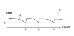
- FIG. 5 is a diagram for explaining a problem of the reference technique.
- the horizontal axis of the graph G1 in FIG. 5 is the axis corresponding to the elapsed time
- the vertical axis is the axis corresponding to the correct answer rate of the machine learning model.
- the line segment l1 shows the relationship between the elapsed time and the correct answer rate of the machine learning model.
- the accuracy of the machine learning model falls below the permissible performance, and the machine learning model and the machine learning of each inspector are executed again.
- the model generator creates a training data set 22B from the training data set 22A, excluding the training data having the correct answer label "first class” and the score is less than the threshold value.
- the training data of the correct label "second class” remains in the training data set 22B.
- the model generator performs machine learning by the error back propagation method so that the output result when each training data of the training data set 22B is input to the inspector 21B approaches the correct answer label of each training data. Train the parameters of layer 21B-2 of.
- the model generator executes machine learning of the inspector 21C by inputting the training data set 22C.
- the model generator executes machine learning with some parameters fixed among the plurality of parameters set in the plurality of layers.
- the parameters of the plurality of layers 21C-1 of the inspector 21C are fixed, and the parameters of the plurality of layers 21C-2 are fine-tuned.
- the model application area is narrowed under different conditions, and the inspectors 21A to 21C have different decision boundaries. Since the inspectors 11A to 11C have different determination boundaries, the output results may differ even if the same input data is input. That is, based on the difference in the output results of the inspectors 11A to 11C trained by the model generator, it is possible to detect a change in the distribution of data that may cause a deterioration in the accuracy of the machine learning model.
- FIG. 7 is a functional block diagram showing the configuration of the model generator according to the present embodiment.
- the model generation device according to the present embodiment includes a communication unit 110, an input unit 120, an output unit 130, a storage unit 140, and a control unit 150.
- the first generation unit 151 and the second generation unit 152 are examples of generation units.
- the output unit 130 outputs data from the control unit 150.
- FIG. 9 is a diagram showing an example of training data.
- the training data will be described as image data, but the training data may be mail spam data, electricity demand forecast, stock price forecast, and poker hand data.
- the training data TD1 and TD1 and 2 are image data of the T-shirt, and are associated with the correct answer label "first class”.
- the training data TDs 3 and 4 are image data of trousers and are associated with the correct label "second class”.
- the training data TDs 5 and 6 are image data of the pullover and are associated with the correct label "third class”.
- the machine learning model data 142 is the data of the machine learning model.
- FIG. 10 is a diagram for explaining an example of a machine learning model.
- the machine learning model 50 has a neural network structure, and has an input layer 50a, a hidden layer 50b, and an output layer 50c.
- the input layer 50a, the hidden layer 50b, and the output layer 50c have a structure in which a plurality of nodes are connected by edges.
- the hidden layer 50b and the output layer 50c have a function called an activation function and a bias value, and the edge has a weight. Parameters such as bias value and weight are set in the plurality of layers.
- it is a value output from the node 51a when the training data corresponding to the correct answer label "first class" is input to each node included in the input layer 50a, and is a value before being input to the softmax function. Is the score of the input training data.
- the training data corresponding to the correct answer label "second class” is input to each node included in the input layer 50a
- the value output from the node 51b and before inputting to the softmax function is used. It is the score of the input training data.
- the training data corresponding to the correct answer label "third class” is input to each node included in the input layer 50a
- the value output from the node 51c and before inputting to the softmax function is used. It is the score of the input training data.
- the machine learning model 50 it is assumed that the machine learning has been executed by inputting the training data set 141.
- each training data of the training data set 141 is input to the input layer 50a so that the output result of each node of the output layer 50c approaches the correct answer label of the input training data.
- the parameters of the machine learning model 50 are trained.
- the machine learning model 50 is trained in parameters by the error backpropagation method.
- the inspector of the identification information "M0” is referred to as “inspector M0".
- the inspector of the identification information "M1” is referred to as “inspector M1”.
- the inspector of the identification information "M2” is referred to as “inspector M2”.
- the inspector of the identification information "M3” is referred to as “inspector M3”.
- the training data table 144 has a plurality of training data sets for learning each inspector.
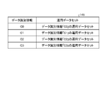
- FIG. 12 is a diagram showing an example of the data structure of the training data table. As shown in FIG. 12, the training data table 144 has data identification information and a training data set. The data identification information is information that identifies the training data set. The training data set is a training data set used when performing machine learning of each inspector.
- the training data set of the data identification information "D1" is the training data set of the training data set 141, which is the training data of the correct answer label "first class” and excludes the training data having a low score.
- the training data set of the data identification information "D1" is referred to as "training data set D1".
- the training data set of the data identification information "D2" is the training data set of the training data set 141, which is the training data of the correct answer label "second class” and excludes the training data having a low score.
- the training data set of the data identification information "D2" is referred to as "training data set D2".
- the training data set of the data identification information "D3" is the training data set of the training data set 141, which is the training data of the correct answer label "third class” and excludes the training data having a low score.
- the training data set of the data identification information "D3" is referred to as "training data set D3".
- the operational data table 145 has an operational data set that is added over time.
- FIG. 13 is a diagram showing an example of the data structure of the operation data table. As shown in FIG. 13, the operation data table 145 has data identification information and an operation data set.
- the data identification information is information that identifies an operational data set.
- the operational data set contains a plurality of operational data. Operational data corresponds to email spam data, electricity demand forecasts, stock price forecasts, poker hand data, image data, and the like.
- the operation data set of the data identification information "C1" is an operation data set collected after T1 hours have elapsed from the start of operation.
- the operational data set of the data identification information “C1” is referred to as “operational data set C1”.
- the operation data set of the data identification information "C2" is an operation data set collected after T2 (T2> T1) time has elapsed from the start of operation.
- the operational data set of the data identification information “C2” is referred to as “operational data set C2”.
- the operation data set of the data identification information "C3" is an operation data set collected after T3 (T3> T2) time has elapsed from the start of operation.
- the operational data set of the data identification information "C3” is referred to as "operational data set C3".
- operation data identification information that uniquely identifies the operation data is given to each operation data included in the operation data sets C0 to C3.
- the operation data sets C0 to C3 are data streamed from the external device to the model generation device 100, and the model generation device 100 registers the data streamed operation data sets C0 to C3 in the operation data table 145.
- the output result table 146 is a table for registering the output results of the inspectors M0 to M3 when the operation data sets C0 to C3 are input to the inspectors M0 to M3.
- the control unit 150 is a processing unit that controls the entire model generation device 100, and has a first generation unit 151, a selection unit 152, a second generation unit 153, and a detection unit 154.
- the control unit 150 is, for example, a processor or the like.
- the first generation unit 151 acquires the training data set 141, inputs the training data set 141 to the inspector M0 before training, and executes machine learning of the inspector M0.
- the training data set 141 is a training data set used when performing machine learning of the machine learning model 50.
- the first generation unit 151 inputs each training data of the training data set 141 to the input layer of the inspector M0, and the inspector M0 so that the output result of each node of the output layer approaches the correct answer label of the input training data. Train multiple parameters in multiple layers of.
- the first generation unit 151 registers the data of the trained inspector M0 in the inspector table 143.
- the data of the inspector M0 includes a plurality of parameters set in the plurality of layers of the inspector M0.
- the inspector M0A includes n layers, and the parameters of each trained layer are set to ⁇ 1 to ⁇ n .
- the selection unit 152 calculates the score of each training data included in the training data set 141, selects training data other than the training data whose score is less than the threshold from the training data set 141, and selects the training data sets D1 to D3. Generate.
- the process of generating the "training data set D1" by the selection unit 152 will be described.
- the selection unit 152 inputs the training data of the correct answer label “first class” from the training data of the training data set 141 into the inspector M0, and calculates the score. When the score becomes equal to or higher than the threshold value, the selection unit 152 selects the training data of the correct answer label “first class” as the training data of the training data set D1. The selection unit 152 repeatedly executes the above processing for other training data of the correct answer label “first class”.
- the selection unit 152 selects the training data of the correct answer labels "second class” and "third class” as it is as the training data of the training data set D1 among the training data of the training data set 141.
- the process of generating the "training data set D2" by the selection unit 152 will be described.
- the selection unit 152 inputs the training data of the correct answer label “second class” from the training data of the training data set 141 into the inspector M0, and calculates the score. When the score is equal to or higher than the threshold value, the selection unit 152 selects the training data of the correct answer label “second class” as the training data of the training data set D2.
- the selection unit 152 repeatedly executes the above processing for other training data of the correct answer label “second class”.
- the process of generating the "training data set D3" by the selection unit 152 will be described.
- the selection unit 152 inputs the training data of the correct answer label “third class” from the training data of the training data set 141 into the inspector M0, and calculates the score. When the score is equal to or higher than the threshold value, the selection unit 152 selects the training data of the correct answer label “third class” as the training data of the training data set D3. The selection unit 152 repeatedly executes the above processing for other training data of the correct answer label “third class”.
- the selection unit 152 selects the training data of the correct answer labels "first class” and "second class” as it is as the training data of the training data set D3 among the training data of the training data set 141.
- the second generation unit 153 explains the process of generating the "inspector M3".
- the second generation unit 153 takes the training data set D3 as an input, diverts a plurality of parameters of the inspector M0 as a plurality of parameters of the inspector M3, and executes machine learning with some parameters fixed. , Generates an inspector M3.
- ⁇ 1 to ⁇ n be a plurality of parameters diverted from the inspector M0.
- the second generation unit 153 sets the initial values of the parameters of the plurality of layers of the inspector M3 to the parameters ⁇ 1 to ⁇ n .
- the second generation unit 153 fixes ⁇ 1 to ⁇ n-2 among the parameters ⁇ 1 to ⁇ n of the inspector M3, and ⁇ n-1 .
- ⁇ n is trained.
- the second generation unit 153 registers the data of the trained inspector M3 in the inspector table 143.
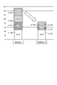
- FIG. 14 is a diagram showing an example of the classification result of each inspector.
- Graph G2-0 shows the classification result of Inspector M0.
- Graph G2-1 shows the classification result of the inspector M1.
- Graph G2-2 shows the classification result of the inspector M2.
- Graph G2-3 shows the classification result of the inspector M3.
- the horizontal axis of each graph is the axis corresponding to the first feature amount of the data, and the vertical axis is the axis corresponding to the second feature amount of the data.
- the detection unit 154 may cause the accuracy deterioration of the machine learning model 50 (or a sign of causing the accuracy deterioration). Detects changes in the distribution of certain data. The detection unit 154 notifies the external device that the change in the distribution of the data has been detected.
- FIG. 15 is a diagram for explaining the processing of the detection unit.
- the inspectors M0 and M1 will be used for explanation.
- the decision boundary of the inspector M0 is set to the decision boundary 70A
- the decision boundary of the inspector M1 is set to the decision boundary 70B.
- the positions of the decision boundary 70A and the decision boundary 70B are different from each other, and the model application area is different.
- one operational data included in the operational data set is appropriately referred to as an “instance”.
- the instance When the instance is located in the model application area 71A, the instance is classified into the first class by the inspector M0. When the instance is located in the model application area 72A, the instance is classified into the second class by the inspector M0.
- the instance When the instance is located in the model application area 71B, the instance is classified into the first class by the inspector M1. When the instance is located in the model application area 72B, the instance is classified into the second class by the inspector M1.
- the instance I1 T1 , I2 T1 , I3 T1 becomes the instance I1 T2 , I2 T2 , I3 T2 .
- the instance I1 T2 is input to the inspector M0
- the instance I1 T2 is located in the model application area 71A and is therefore classified as a “first class”.
- the instance I2 T1 is located in the model application area 71A and is therefore classified as a “first class”.
- the instance I3 T2 is input to the inspector M0, the instance I3 T2 is located in the model application area 72A and is therefore classified as a “second class”.
- the detection unit 154 may cause the accuracy of the machine learning model 50 to deteriorate. Detects changes in the distribution of certain data. Further, the detection unit 154 can detect the instance I1 T2 that has caused the deterioration of accuracy.
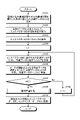
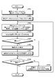
- FIG. 16 is a flowchart (1) showing a processing procedure of the model generator according to the present embodiment.
- the model generator 100 acquires the training data set 141 used when the machine learning of the machine learning model 50 to be monitored is executed (step S101).
- the first generation unit 151 of the model generation device 100 inputs the training data set 141 and executes machine learning of the inspector M0 (step S102).
- the first generation unit 151 stores the parameters of the inspector M0 in the inspector table 143 (step S103).
- the second generation unit 153 executes machine learning processing (step S109).
- the second generation unit 153 registers the data of the trained plurality of inspectors in the inspector table 143 (step S110).
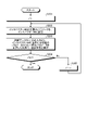
- FIG. 17 is a flowchart showing a processing procedure of machine learning processing.
- the second generation unit 153 sets a plurality of parameters of the inspector M0 in the inspector Mi (step S202).
- the second generation unit 153 takes the training data set Di as an input, and executes machine learning in a state where some of the parameters included in the inspector Mi are fixed (step S203).
- FIG. 18 is a flowchart (2) showing a processing procedure of the model generator according to the present embodiment.
- the detection unit 154 of the model generation device 100 acquires an operation data set from the operation data table 145 (step S301).
- the detection unit 154 selects one instance from the operation data set (step S302).
- the detection unit 155 inputs the selected instance to each inspector M0 to M3, acquires the output result, and registers it in the output result table 146 (step S303).
- the detection unit 155 refers to the output result table 146 and determines whether or not each output result is different (step S304).
- step S305 If the output results are not different (steps S305, No), the detection unit 154 shifts to step S308. If the output results are different (steps S305, Yes), the detection unit 154 shifts to step S306.
- the detection unit 154 detects the deterioration of accuracy (step S306).
- the detection unit 154 notifies the external device that the accuracy deterioration has been detected (step S307).
- the model generator 100 determines whether or not all the instances have been selected (step S308).
- step S308 When all the instances are selected (step S308, Yes), the model generation device 100 ends the process. On the other hand, if all the instances are not selected (step S308, No), the model generation device 100 proceeds to step S309.
- the detection unit 154 selects one unselected instance from the operation data set (step S309), and proceeds to step S303.
- the model generation device 100 diverts a plurality of trained parameters of the inspector M0 and executes the machine learning with some parameters fixed. Therefore, the calculation cost of the inspectors M1 to M3 can be realized at a calculation cost smaller than the calculation cost of the inspector M0. Since the calculation cost of the inspectors M1 to M3 can be realized with a small calculation cost, the calculation cost required for continuous operation monitoring of the machine learning model can be reduced.
- FIG. 19 is a diagram for explaining the effect of the model generator according to the present embodiment.
- t1-M0 is the time required for the reference device to train the inspector M0.
- t1-M1 is the time required for the reference device to train the inspector M1.
- t1-M2 is the time required for the reference device to train the inspector M2.
- t1-M3 is the time required for the reference device to train the inspector M3.
- t1-M0 is "49.9 seconds”
- t1-M1 is “33.92 seconds”
- t1-M2 is “31.87 seconds”
- t1-M3 is "34.3 seconds”. Therefore, the time for the reference device to train the inspectors M0 to M3 is "150.03 seconds”.
- T2-M0 is the time required for the model generator 100 to train the inspector M0.
- t2-M1 is the time required for the model generator 100 to train the inspector M1.
- t2-M2 is the time required for the model generator 100 to train the inspector M2.
- t2-M3 is the time required for the model generator 100 to train the inspector M3.
- t2-M0 is "49.9 seconds”
- t2-M1 is “10.57 seconds”
- t2-M2 is “10.59 seconds”
- t2-M3 is "11.18 seconds”. Therefore, the time for the model generator 100 to train the inspectors M0 to M3 is "82.28 seconds”.
- the time for the model generator 100 to train the inspectors M0 to M3 is shorter than the time for the reference device to train the inspectors M0 to M3, and the calculation cost can be reduced.
- the model application area is narrowed under different conditions, and the inspectors have different decision boundaries. Since the inspectors M1 to M3 have different determination boundaries, the output results may differ even if the same input data is input. That is, the model generator 100 detects changes in the distribution of data in the operational data set, which may cause deterioration in the accuracy of the machine learning model, based on the difference in the output results of the inspectors M1 to M3. Can be done.
- the model generation device 100 generates the inspector M0 by executing machine learning with the training data set 141 as an input. This makes it possible to train a plurality of parameters to be initialized in the inspectors M1 to M3.
- each program 207a to 207d does not necessarily have to be stored in the hard disk device 507 from the beginning.
- each program is stored in a "portable physical medium" such as a flexible disk (FD), a CD-ROM, a DVD disk, a magneto-optical disk, or an IC card inserted in the computer 200. Then, the computer 200 may read and execute each of the programs 207a to 207d.
Landscapes
- Engineering & Computer Science (AREA)
- Theoretical Computer Science (AREA)
- Software Systems (AREA)
- Data Mining & Analysis (AREA)
- Evolutionary Computation (AREA)
- Medical Informatics (AREA)
- Computer Vision & Pattern Recognition (AREA)
- Physics & Mathematics (AREA)
- Computing Systems (AREA)
- General Engineering & Computer Science (AREA)
- General Physics & Mathematics (AREA)
- Mathematical Physics (AREA)
- Artificial Intelligence (AREA)
- Testing And Monitoring For Control Systems (AREA)
Priority Applications (3)
| Application Number | Priority Date | Filing Date | Title |
|---|---|---|---|
| PCT/JP2020/035841 WO2022064570A1 (ja) | 2020-09-23 | 2020-09-23 | モデル生成プログラム、モデル生成方法及びモデル生成装置 |
| JP2022551471A JP7448026B2 (ja) | 2020-09-23 | 2020-09-23 | 検知プログラム、モデル生成プログラム、検知方法、モデル生成方法、検知装置及びモデル生成装置 |
| US18/164,088 US20230186165A1 (en) | 2020-09-23 | 2023-02-03 | Computer-readable recording medium storing model generation program, model generation method, and model generation device |
Applications Claiming Priority (1)
| Application Number | Priority Date | Filing Date | Title |
|---|---|---|---|
| PCT/JP2020/035841 WO2022064570A1 (ja) | 2020-09-23 | 2020-09-23 | モデル生成プログラム、モデル生成方法及びモデル生成装置 |
Related Child Applications (1)
| Application Number | Title | Priority Date | Filing Date |
|---|---|---|---|
| US18/164,088 Continuation US20230186165A1 (en) | 2020-09-23 | 2023-02-03 | Computer-readable recording medium storing model generation program, model generation method, and model generation device |
Publications (1)
| Publication Number | Publication Date |
|---|---|
| WO2022064570A1 true WO2022064570A1 (ja) | 2022-03-31 |
Family
ID=80845575
Family Applications (1)
| Application Number | Title | Priority Date | Filing Date |
|---|---|---|---|
| PCT/JP2020/035841 Ceased WO2022064570A1 (ja) | 2020-09-23 | 2020-09-23 | モデル生成プログラム、モデル生成方法及びモデル生成装置 |
Country Status (3)
| Country | Link |
|---|---|
| US (1) | US20230186165A1 (https=) |
| JP (1) | JP7448026B2 (https=) |
| WO (1) | WO2022064570A1 (https=) |
Citations (2)
| Publication number | Priority date | Publication date | Assignee | Title |
|---|---|---|---|---|
| JP2018063504A (ja) * | 2016-10-12 | 2018-04-19 | 株式会社リコー | 生成モデル学習方法、装置及びプログラム |
| JP2020052935A (ja) * | 2018-09-28 | 2020-04-02 | 三菱電機インフォメーションシステムズ株式会社 | 学習済みモデルを生成する方法、データを分類する方法、コンピュータおよびプログラム |
Family Cites Families (15)
| Publication number | Priority date | Publication date | Assignee | Title |
|---|---|---|---|---|
| US9165051B2 (en) * | 2010-08-24 | 2015-10-20 | Board Of Trustees Of The University Of Illinois | Systems and methods for detecting a novel data class |
| US9336484B1 (en) * | 2011-09-26 | 2016-05-10 | The United States Of America As Represented By The Administrator Of The National Aeronautics And Space Administration (Nasa) | System and method for outlier detection via estimating clusters |
| US9031897B2 (en) * | 2012-03-23 | 2015-05-12 | Nuance Communications, Inc. | Techniques for evaluation, building and/or retraining of a classification model |
| JP6650468B2 (ja) * | 2015-04-16 | 2020-02-19 | シーメンス アクチエンゲゼルシヤフトSiemens Aktiengesellschaft | 自動化システムを動作させる方法及び装置 |
| EP3459022A4 (en) * | 2016-05-16 | 2020-02-19 | Purepredictive, Inc. | Predictive drift detection and correction |
| US20180307741A1 (en) * | 2017-04-25 | 2018-10-25 | Intel Corporation | Filtering training data for simpler rbf models |
| US10209974B1 (en) * | 2017-12-04 | 2019-02-19 | Banjo, Inc | Automated model management methods |
| US10599984B1 (en) * | 2018-03-20 | 2020-03-24 | Verily Life Sciences Llc | Validating a machine learning model after deployment |
| US10810512B1 (en) * | 2018-03-21 | 2020-10-20 | Verily Life Sciences Llc | Validating a machine learning model prior to deployment |
| US20200285994A1 (en) * | 2018-07-30 | 2020-09-10 | Rakuten, Inc. | Determination system, determination method and program |
| US11574144B2 (en) * | 2019-01-07 | 2023-02-07 | Microsoft Technology Licensing, Llc | Performance of a computer-implemented model that acts as a multi-class classifier |
| WO2020219685A1 (en) * | 2019-04-23 | 2020-10-29 | Sciencelogic, Inc. | Distributed learning anomaly detector |
| US11481682B2 (en) * | 2020-05-07 | 2022-10-25 | International Business Machines Corporation | Dataset management in machine learning |
| US11475235B2 (en) * | 2020-05-15 | 2022-10-18 | Equifax Inc. | Clustering techniques for machine learning models |
| US10970650B1 (en) * | 2020-05-18 | 2021-04-06 | King Abdulaziz University | AUC-maximized high-accuracy classifier for imbalanced datasets |
-
2020
- 2020-09-23 WO PCT/JP2020/035841 patent/WO2022064570A1/ja not_active Ceased
- 2020-09-23 JP JP2022551471A patent/JP7448026B2/ja active Active
-
2023
- 2023-02-03 US US18/164,088 patent/US20230186165A1/en active Pending
Patent Citations (2)
| Publication number | Priority date | Publication date | Assignee | Title |
|---|---|---|---|---|
| JP2018063504A (ja) * | 2016-10-12 | 2018-04-19 | 株式会社リコー | 生成モデル学習方法、装置及びプログラム |
| JP2020052935A (ja) * | 2018-09-28 | 2020-04-02 | 三菱電機インフォメーションシステムズ株式会社 | 学習済みモデルを生成する方法、データを分類する方法、コンピュータおよびプログラム |
Also Published As
| Publication number | Publication date |
|---|---|
| US20230186165A1 (en) | 2023-06-15 |
| JPWO2022064570A1 (https=) | 2022-03-31 |
| JP7448026B2 (ja) | 2024-03-12 |
Similar Documents
| Publication | Publication Date | Title |
|---|---|---|
| US11347972B2 (en) | Training data generation method and information processing apparatus | |
| AU2016200021B2 (en) | End-to-end project management | |
| EP4053757A1 (en) | Degradation suppression program, degradation suppression method, and information processing device | |
| JP2019185422A (ja) | 故障予知方法、故障予知装置および故障予知プログラム | |
| US11132584B2 (en) | Model reselection for accommodating unsatisfactory training data | |
| JP7306469B2 (ja) | 検出方法、検出プログラムおよび情報処理装置 | |
| JP7400827B2 (ja) | 検出方法、検出プログラムおよび情報処理装置 | |
| US11599884B2 (en) | Identification of behavioral pattern of simulated transaction data | |
| Laiou et al. | Autonomous Fault Detection and Diagnosis in Wireless Sensor Networks Using Decision Trees. | |
| JPWO2014199920A1 (ja) | 予測関数作成装置、予測関数作成方法、及びプログラム | |
| US11416302B2 (en) | Computer system and method for determining of resource allocation | |
| JP7276487B2 (ja) | 作成方法、作成プログラム及び情報処理装置 | |
| JP2019028671A (ja) | 情報処理装置、情報処理方法、コンピュータプログラム、及び記憶媒体 | |
| JP7272455B2 (ja) | 検出方法、検出プログラム及び情報処理装置 | |
| JP7424507B2 (ja) | 検知プログラム、検知方法および検知装置 | |
| US20220222545A1 (en) | Generation method, non-transitory computer-readable storage medium, and information processing device | |
| JP7675562B2 (ja) | 学習装置、方法およびプログラム | |
| JP7448026B2 (ja) | 検知プログラム、モデル生成プログラム、検知方法、モデル生成方法、検知装置及びモデル生成装置 | |
| JP7371695B2 (ja) | 劣化検出方法、劣化検出プログラムおよび情報処理装置 | |
| JP4308113B2 (ja) | データ分析装置及びその方法、プログラム | |
| US20220237459A1 (en) | Generation method, computer-readable recording medium storing generation program, and information processing apparatus | |
| US20220215272A1 (en) | Deterioration detection method, computer-readable recording medium storing deterioration detection program, and information processing apparatus | |
| JP7589819B2 (ja) | 評価プログラム、評価方法及び精度評価装置 | |
| US20060074830A1 (en) | System, method for deploying computing infrastructure, and method for constructing linearized classifiers with partially observable hidden states | |
| JPWO2023223448A5 (https=) |
Legal Events
| Date | Code | Title | Description |
|---|---|---|---|
| 121 | Ep: the epo has been informed by wipo that ep was designated in this application |
Ref document number: 20955164 Country of ref document: EP Kind code of ref document: A1 |
|
| ENP | Entry into the national phase |
Ref document number: 2022551471 Country of ref document: JP Kind code of ref document: A |
|
| NENP | Non-entry into the national phase |
Ref country code: DE |
|
| 122 | Ep: pct application non-entry in european phase |
Ref document number: 20955164 Country of ref document: EP Kind code of ref document: A1 |