WO2022059790A1 - Film décoratif, corps moulé décoratif, panneau décoratif et dispositif électronique - Google Patents
Film décoratif, corps moulé décoratif, panneau décoratif et dispositif électronique Download PDFInfo
- Publication number
- WO2022059790A1 WO2022059790A1 PCT/JP2021/034417 JP2021034417W WO2022059790A1 WO 2022059790 A1 WO2022059790 A1 WO 2022059790A1 JP 2021034417 W JP2021034417 W JP 2021034417W WO 2022059790 A1 WO2022059790 A1 WO 2022059790A1
- Authority
- WO
- WIPO (PCT)
- Prior art keywords
- layer
- liquid crystal
- decorative
- group
- mass
- Prior art date
Links
Images


Classifications
-
- C—CHEMISTRY; METALLURGY
- C09—DYES; PAINTS; POLISHES; NATURAL RESINS; ADHESIVES; COMPOSITIONS NOT OTHERWISE PROVIDED FOR; APPLICATIONS OF MATERIALS NOT OTHERWISE PROVIDED FOR
- C09K—MATERIALS FOR MISCELLANEOUS APPLICATIONS, NOT PROVIDED FOR ELSEWHERE
- C09K19/00—Liquid crystal materials
- C09K19/52—Liquid crystal materials characterised by components which are not liquid crystals, e.g. additives with special physical aspect: solvents, solid particles
- C09K19/58—Dopants or charge transfer agents
- C09K19/586—Optically active dopants; chiral dopants
-
- C—CHEMISTRY; METALLURGY
- C09—DYES; PAINTS; POLISHES; NATURAL RESINS; ADHESIVES; COMPOSITIONS NOT OTHERWISE PROVIDED FOR; APPLICATIONS OF MATERIALS NOT OTHERWISE PROVIDED FOR
- C09K—MATERIALS FOR MISCELLANEOUS APPLICATIONS, NOT PROVIDED FOR ELSEWHERE
- C09K19/00—Liquid crystal materials
- C09K19/04—Liquid crystal materials characterised by the chemical structure of the liquid crystal components, e.g. by a specific unit
- C09K19/38—Polymers
- C09K19/3833—Polymers with mesogenic groups in the side chain
- C09K19/3838—Polyesters; Polyester derivatives
-
- B—PERFORMING OPERATIONS; TRANSPORTING
- B32—LAYERED PRODUCTS
- B32B—LAYERED PRODUCTS, i.e. PRODUCTS BUILT-UP OF STRATA OF FLAT OR NON-FLAT, e.g. CELLULAR OR HONEYCOMB, FORM
- B32B27/00—Layered products comprising a layer of synthetic resin
-
- B—PERFORMING OPERATIONS; TRANSPORTING
- B32—LAYERED PRODUCTS
- B32B—LAYERED PRODUCTS, i.e. PRODUCTS BUILT-UP OF STRATA OF FLAT OR NON-FLAT, e.g. CELLULAR OR HONEYCOMB, FORM
- B32B7/00—Layered products characterised by the relation between layers; Layered products characterised by the relative orientation of features between layers, or by the relative values of a measurable parameter between layers, i.e. products comprising layers having different physical, chemical or physicochemical properties; Layered products characterised by the interconnection of layers
- B32B7/02—Physical, chemical or physicochemical properties
- B32B7/023—Optical properties
-
- C—CHEMISTRY; METALLURGY
- C09—DYES; PAINTS; POLISHES; NATURAL RESINS; ADHESIVES; COMPOSITIONS NOT OTHERWISE PROVIDED FOR; APPLICATIONS OF MATERIALS NOT OTHERWISE PROVIDED FOR
- C09K—MATERIALS FOR MISCELLANEOUS APPLICATIONS, NOT PROVIDED FOR ELSEWHERE
- C09K19/00—Liquid crystal materials
- C09K19/04—Liquid crystal materials characterised by the chemical structure of the liquid crystal components, e.g. by a specific unit
- C09K2019/0444—Liquid crystal materials characterised by the chemical structure of the liquid crystal components, e.g. by a specific unit characterized by a linking chain between rings or ring systems, a bridging chain between extensive mesogenic moieties or an end chain group
- C09K2019/0448—Liquid crystal materials characterised by the chemical structure of the liquid crystal components, e.g. by a specific unit characterized by a linking chain between rings or ring systems, a bridging chain between extensive mesogenic moieties or an end chain group the end chain group being a polymerizable end group, e.g. -Sp-P or acrylate
-
- C—CHEMISTRY; METALLURGY
- C09—DYES; PAINTS; POLISHES; NATURAL RESINS; ADHESIVES; COMPOSITIONS NOT OTHERWISE PROVIDED FOR; APPLICATIONS OF MATERIALS NOT OTHERWISE PROVIDED FOR
- C09K—MATERIALS FOR MISCELLANEOUS APPLICATIONS, NOT PROVIDED FOR ELSEWHERE
- C09K19/00—Liquid crystal materials
- C09K19/52—Liquid crystal materials characterised by components which are not liquid crystals, e.g. additives with special physical aspect: solvents, solid particles
- C09K2019/528—Surfactants
-
- C—CHEMISTRY; METALLURGY
- C09—DYES; PAINTS; POLISHES; NATURAL RESINS; ADHESIVES; COMPOSITIONS NOT OTHERWISE PROVIDED FOR; APPLICATIONS OF MATERIALS NOT OTHERWISE PROVIDED FOR
- C09K—MATERIALS FOR MISCELLANEOUS APPLICATIONS, NOT PROVIDED FOR ELSEWHERE
- C09K2219/00—Aspects relating to the form of the liquid crystal [LC] material, or by the technical area in which LC material are used
- C09K2219/03—Aspects relating to the form of the liquid crystal [LC] material, or by the technical area in which LC material are used in the form of films, e.g. films after polymerisation of LC precursor
Definitions
- This disclosure relates to decorative films, decorative molded bodies, decorative panels, and electronic devices.
- a decorative molded body in which a decorative film is placed on the surface of the resin molded body to color the surface of the resin molded body to a desired hue, or a desired pattern is provided on the surface of the resin molded body.
- the decorative molded body is obtained, for example, by arranging a decorative film in a mold in advance and injecting a base resin into the mold, and the decorative film is integrated on the surface of the resin molded body. Has a structure that has been formed.
- injection molding of the base resin is generally referred to as film insert molding or simply insert molding.
- the decorative molded body may be manufactured by attaching a decorative film to the molded body after molding.
- Japanese Patent Application Laid-Open No. 2001-105795 describes a hot stamp foil characterized in that a cholesteric liquid crystal polymer layer having a selective reflection wavelength range in visible light is laminated as a transfer layer. Has been done. Further, Japanese Patent Application Laid-Open No. 2017-97114 describes that the retroreflective property is improved by subjecting the cholesteric liquid crystal layer to uneven processing.
- An object to be solved by one embodiment of the present disclosure is to provide a decorative film having high brilliance, high saturation, and abundant color change depending on the viewing direction.
- An object to be solved by another embodiment of the present disclosure is to provide a decorative molded body using the above-mentioned decorative film.
- An object to be solved by another embodiment of the present disclosure is to provide a decorative panel using the above-mentioned decorative film.
- An object to be solved by another embodiment of the present disclosure is to provide an electronic device using the decorative panel.
- the disclosure includes the following aspects: ⁇ 1> It has a base material and an optical reflection layer that develops color due to optical interference or structural color, and at least two or more optical reflection layers are laminated. A decorative film in which the diffuse reflectance of each optical reflective layer is different from each other, or a print layer is laminated between the optical reflective layers. ⁇ 2> The decorative film according to ⁇ 1>, wherein at least one of the optical reflection layers is a layer containing a cholesteric liquid crystal compound. ⁇ 3> A decorative molded body containing the decorative film according to ⁇ 1> or ⁇ 2>. ⁇ 4> A decorative panel comprising the decorative film according to ⁇ 1> or ⁇ 2>. ⁇ 5> An electronic device including the decorative panel according to ⁇ 4>.
- a decorative film having high brilliance, high saturation, and abundant color change depending on the viewing direction it is possible to provide a decorative film having high brilliance, high saturation, and abundant color change depending on the viewing direction.
- a decorative molded body using the above-mentioned decorative film is provided.
- a decorative panel using the above-mentioned decorative film is provided.
- an electronic device using the decorative panel is provided.
- FIG. 1 is a schematic cross-sectional view showing an example of a decorative film according to the present disclosure.
- FIG. 2 is a schematic cross-sectional view showing an example of the decorative film according to the present disclosure.
- FIG. 3 is a schematic cross-sectional view showing an example of the decorative molded body according to the present disclosure.
- FIG. 4 is a schematic cross-sectional view showing an example of the decorative molded body according to the present disclosure.
- FIG. 5 is a schematic cross-sectional view showing an example of the decorative molded body according to the present disclosure.
- FIG. 6 is a schematic cross-sectional view showing an example of the decorative panel according to the present disclosure.
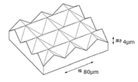
- FIG. 7 is a schematic plan view showing an example of a transparent body having a concavo-convex structure according to the present disclosure.
- FIG. 8 is a schematic perspective view of a transparent body having a concavo-convex structure according to the present disclosure.
- FIG. 9 is a schematic view showing a black image pattern which is
- the notation that does not describe substitution or non-substitution includes those having no substituent as well as those having a substituent.
- the "alkyl group” includes not only an alkyl group having no substituent (unsubstituted alkyl group) but also an alkyl group having a substituent (substituted alkyl group).
- Light in the present disclosure means active light or radiation.
- the “active light” or “radiation” in the present disclosure means, for example, the emission line spectrum of a mercury lamp, far ultraviolet rays typified by an excimer laser, extreme ultraviolet rays (EUV light: Extreme Ultraviolet light), X-rays, and electron beams (EB:). It means Electron Beam) and the like.
- exposure in the present disclosure means not only exposure with emission line spectrum of mercury lamp, far ultraviolet rays represented by excimer laser, extreme ultraviolet rays, X-rays, EUV light, etc., but also electron beam and ion beam. Also includes exposure with particle beams such as.
- "-" is used to mean that the numerical values described before and after it are included as the lower limit value and the upper limit value.
- (meth) acrylate represents acrylate and methacrylate
- (meth) acrylic represents acrylic and methacrylic
- the weight average molecular weight (Mw) of the resin component, the number average molecular weight (Mn) of the resin component, and the dispersion degree (also referred to as molecular weight distribution) (Mw / Mn) of the resin component are referred to as GPC (Gel Permeation Chromatography) apparatus.
- the amount of each component in the composition means the total amount of the plurality of applicable substances present in the composition when a plurality of the substances corresponding to each component are present in the composition, unless otherwise specified. do.
- the term "process” is included in this term not only as an independent process but also as long as the intended purpose of the process is achieved even if it cannot be clearly distinguished from other processes.
- the "total solid content” means the total mass of the components excluding the solvent from the total composition of the composition.
- the “solid content” is a component obtained by removing the solvent from the entire composition of the composition, and may be, for example, a solid or a liquid at 25 ° C. Further, in the present disclosure, a combination of two or more preferred embodiments is a more preferred embodiment.
- the decorative film according to the embodiment of the present disclosure has a base material and an optical reflection layer that develops color due to optical interference or structural color, and at least two or more optical reflection layers are laminated. Further, in the decorative film according to the embodiment of the present disclosure, the diffuse reflection properties of the optical reflection layers are different from each other, or the print layer is laminated between the optical reflection layers.
- the use of the decorative film according to the embodiment of the present disclosure is not particularly limited, and is, for example, electronic devices (for example, wearable devices and smartphones), home appliances, audio products, computers, displays, in-vehicle products, watches, and the like. It can be used to decorate accessories, optics, doors, windowpanes, and building materials.
- the decorative film according to the embodiment of the present disclosure can be suitably used for decorating electronic devices (for example, wearable devices and smartphones).
- the decorative film according to the embodiment of the present disclosure is also excellent in three-dimensional moldability, it is suitable as a decorative film for molding used for molding such as three-dimensional molding and insert molding, and is three-dimensional. It is more suitable as a decorative film for molding.
- the decorative film has high brilliance, high saturation, and abundant color change depending on the viewing direction (for example, useful as a material for a decorative molded body).
- decorative films are provided.
- a plurality of optical reflection layers are laminated. By laminating a plurality of optical reflection layers, it is possible to provide a decorative film having high brilliance.
- each optical reflective layer has different diffuse reflectance. Due to the different diffuse reflectivity, the reflected color of each optical reflection layer is visually recognized independently, the color is rich (that is, high saturation), and the color changes greatly depending on the viewing angle (that is, the color is different depending on the viewing direction). We can provide high-impact designs (rich in variety).
- the decorative film according to the embodiment of the present disclosure has a print layer between the optical reflection layers of the plurality of optical reflection layers.
- the print layer By having the print layer, the complementary color light transmitted from the optical reflection layer of the upper layer is absorbed by the print layer, and the color of each optical reflection layer can be visually recognized without being mixed with the optical reflection layer of the lower layer.
- the hue changes greatly depending on the viewing angle (that is, the hue changes abundantly depending on the viewing direction), and the hue is rich (that is, high saturation). )
- the design can be provided.
- “rich in color change depending on the viewing direction” means, for example, when the object is visually recognized from an angle perpendicular to the surface direction of the object and 45 ° with respect to the surface direction of the object. It means that the color change is large when the object is visually recognized from an angle.
- the above effects are preferable in that the impact of the design can be improved.
- the decorative film according to one embodiment of the present disclosure has a base material.
- the base material may be a support.
- a conventionally known base material can be used without particular limitation as a base material used for molding such as three-dimensional molding and insert molding, and may be appropriately selected depending on the suitability for molding. Further, the shape and material of the base material are not particularly limited and may be appropriately selected as desired.
- the base material is preferably a resin base material, and more preferably a resin film, from the viewpoint of ease of molding and chipping resistance.
- Specific base materials include, for example, polyethylene terephthalate (PET), polyethylene naphthalate (PEN), acrylic resin, urethane resin, urethane-acrylic resin, polycarbonate (PC), acrylic-polycarbonate resin, and triacetyl cellulose (TAC). , Cycloolefin polymer (COP), and resin films containing resins such as acryliconitrile / butadiene / styrene copolymer resin (ABS resin).
- the base material is preferably polyethylene terephthalate (PET), acrylic resin, polycarbonate, or polypropylene, preferably polyethylene terephthalate (PET), acrylic resin, or polycarbonate from the viewpoint of moldability and strength. It is more preferable to have.
- the base material may be a laminated resin base material having two or more layers. For example, a laminated film including an acrylic resin layer and a polycarbonate layer is preferable.
- the base material may contain additives, if necessary.
- additives include, for example, lubricants (eg, mineral oils, hydrocarbons, fatty acids, alcohols, fatty acid esters, fatty acid amides, metal soaps, natural waxes, and silicones), inorganic flame retardants (eg, magnesium hydroxide, etc.). And aluminum hydroxide), halogen-based organic flame retardants, phosphorus-based organic flame retardants, organic or inorganic fillers (eg, metal powder, talc, calcium carbonate, potassium titanate, glass fiber, carbon fiber, and wood flour). ), Antioxidants, UV inhibitors, lubricants, dispersants, coupling agents, foaming agents, colorants, and engineering plastics other than the resins mentioned above.
- Engineering plastics include, for example, polyolefins, polyesters, polyacetals, polyamides, and polyphenylene ethers.
- a commercially available product may be used as the base material.
- Commercially available products include, for example, Technoroy (registered trademark) series (acrylic resin film or acrylic resin / polycarbonate resin laminated film, manufactured by Sumitomo Chemical Co., Ltd.), ABS film (manufactured by Okamoto Co., Ltd.), ABS sheet (Sekisui Molding Industry Co., Ltd.). (Manufactured by Co., Ltd.), Teflex (registered trademark) series (PET film, manufactured by Teijin Film Solution Co., Ltd.), Lumirer (registered trademark) easy-molding type (PET film, manufactured by Toray Co., Ltd.), and Pure Thermo (polypropylene). Film, manufactured by Idemitsu Unitech Co., Ltd.) can be mentioned.
- the thickness of the base material is determined according to, for example, the intended use of the molded product to be produced and the handleability, and is not particularly limited.
- the lower limit of the thickness of the base material is preferably 1 ⁇ m or more, more preferably 10 ⁇ m or more, further preferably 20 ⁇ m or more, and particularly preferably 30 ⁇ m or more.
- the upper limit of the thickness of the base material is preferably 500 ⁇ m or less, more preferably 200 ⁇ m or less, and particularly preferably 100 ⁇ m or less.
- the decorative film according to the embodiment of the present disclosure has an optical reflection layer that develops color due to optical interference or structural color, and at least two or more optical reflection layers are laminated.
- the optical reflective layer examples include a layer containing a cholesteric liquid crystal compound (hereinafter, also referred to as “cholesteric liquid crystal layer”), a layer containing flat metal particles, an optical multilayer film, a metal thin film, and a layer containing a chromic material. Be done.
- a cholesteric liquid crystal layer, a metal thin film (hereinafter, may be referred to as a “mirror layer”), or a layer including an optical multilayer film is preferable from the viewpoint of easily obtaining brilliance.
- a metal thin film is more preferable, and a cholesteric liquid crystal layer is particularly preferable.
- it is preferable that at least one of the optical reflection layers is a cholesteric liquid crystal layer.
- the material of the metal thin film is preferably a metal that is not easily oxidized such as In, Ag, and Zn, and it is preferable to form a thin film layer by using a vapor phase method such as thin film deposition or sputtering process. In is more preferable from the viewpoint of high brightness.
- the cholesteric liquid crystal layer is a layer containing a cholesteric liquid crystal compound, and is formed by curing a liquid crystal composition.
- the liquid crystal composition is a composition containing a cholesteric liquid crystal compound.
- the cholesteric liquid crystal compound used in the present disclosure at least a cholesteric liquid crystal compound having one ethylenically unsaturated group or one cyclic ether group is used from the viewpoint of moldability and temporary support peeling property. Is preferable.
- the liquid crystal composition for forming the cholesteric liquid crystal layer is, for example, a cholesteric liquid crystal compound having one ethylenically unsaturated group or one cyclic ether group, 25 mass by mass with respect to the total solid content of the liquid crystal composition. % Or more, and may further contain other components (for example, a chiral agent, an orientation control agent, a polymerization initiator, and an orientation aid).
- the liquid crystal composition contains 25% by mass or more of the cholesteric liquid crystal compound having one ethylenically unsaturated group or one cyclic ether group (hereinafter, also referred to as “specific liquid crystal compound”) as the cholesteric liquid crystal compound. Is preferable.
- the ethylenically unsaturated group in the specific liquid crystal compound is not particularly limited, and examples thereof include a (meth) acryloxy group, a (meth) acrylamide group, a vinyl group, a vinyl ester group, and a vinyl ether group.
- the ethylenically unsaturated group is preferably a (meth) acryloxy group, a (meth) acrylamide group, or an aromatic vinyl group, and is preferably a (meth) acryloxy group or a (meth) acrylamide group. Is more preferable, and it is particularly preferable that it is a (meth) acrylamide group.
- the cyclic ether group in the specific liquid crystal compound is not particularly limited, but from the viewpoint of reactivity, it is preferably an epoxy group or an oxetanyl group, and particularly preferably an oxetanyl group.
- the specific liquid crystal compound is preferably a cholesteric liquid crystal compound having one ethylenically unsaturated group from the viewpoint of reactivity, suppression of reflectance change and suppression of color change after molding. It is more preferable that the liquid crystal composition contains 25% by mass or more of the cholesteric liquid crystal compound having one ethylenically unsaturated group with respect to the total solid content of the liquid crystal composition.
- the specific liquid crystal compound may have both an ethylenically unsaturated group and a cyclic ether group in one molecule, but the number of ethylenically unsaturated groups is one or a cyclic ether group. It is assumed that the number of is one. Further, if the number of ethylenically unsaturated groups in the specific liquid crystal compound is one, for example, the specific liquid crystal compound is a compound having one ethylenically unsaturated group and one or more cyclic ether groups. May be good.
- the liquid crystal composition may contain a radical polymerization initiator from the viewpoint of suppressing the change in reflectance and suppressing the change in color after molding. It is more preferable to include a photoradical polymerization initiator.
- the liquid crystal composition may contain a cationic polymerization initiator from the viewpoint of suppressing the change in reflectance after molding and suppressing the change in color. It is more preferable to include a photocationic polymerization initiator.
- the specific liquid crystal compound is preferably a cholesteric liquid crystal compound having both an ethylenically unsaturated group and a cyclic ether group from the viewpoint of suppressing changes in reflectance and color after molding, and is preferably one ethylenically non-polyplastic compound. More preferably, it is a cholesteric liquid crystal compound having a saturated group and one cyclic ether group.
- the specific liquid crystal compound may be a rod-shaped liquid crystal compound or a disk-shaped liquid crystal compound as long as it is a compound having a liquid crystal structure.
- the specific liquid crystal compound is preferably a rod-shaped liquid crystal compound from the viewpoint of easy adjustment of the pitch of the spiral structure in the cholesteric liquid crystal layer, and suppression of reflectance change and color tint change after molding.
- rod-shaped liquid crystal compound examples include azomethines, azoxys, cyanobiphenyls, cyanophenyl esters, benzoic acid esters, cyclohexanecarboxylic acid phenyl esters, cyanophenylcyclohexanes, cyano-substituted phenylpyrimidins, and alkoxy-substituted phenylpyrimidins. Phenyldioxans, trans, or alkenylcyclohexylbenzonitriles are preferably used. Not only the small molecule liquid crystal compound as described above, but also a liquid crystal polymer compound can be used. Examples of the rod-shaped liquid crystal compound include "Makromol.
- Compounds having one saturated group or one cyclic ether group can be used.
- the rod-shaped liquid crystal compound for example, among the compounds described in JP-A No. 11-513019 and JP-A-2007-279688, one ethylenically unsaturated group or one cyclic ether group is used.
- the compound to be possessed can be preferably used.
- the cholesteric liquid crystal layer is more preferably a layer whose orientation is fixed by polymerization of a rod-shaped liquid crystal compound.
- the disk-shaped liquid crystal compound for example, among the compounds described in JP-A-2007-108732 or JP-A-2010-244038, a compound having one ethylenically unsaturated group or one cyclic ether group. Can be preferably used.
- Specific examples of the specific liquid crystal compound include the compounds shown below, but it goes without saying that the specific liquid crystal compounds are not limited thereto.
- the liquid crystal composition may contain one type of the specific liquid crystal compound alone or may contain two or more types.
- the content of the specific liquid crystal compound is preferably 25% by mass or more with respect to the total solid content of the liquid crystal composition. When the content of the specific liquid crystal compound is 25% by mass or more, a decorative film having a small change in reflectance after molding can be obtained. Further, the content of the specific liquid crystal compound is preferably 30% by mass or more, preferably 40% by mass or more, based on the total solid content of the liquid crystal composition, from the viewpoint of suppressing the change in reflectance and suppressing the change in color after molding. It is more preferably 60% by mass or more and 99% by mass or less, and particularly preferably 80% by mass or more and 98% by mass or less.
- the liquid crystal composition may contain other cholesteric liquid crystal compounds (hereinafter, also simply referred to as “other liquid crystal compounds”) other than the specific liquid crystal compound.
- other liquid crystal compounds include a cholesteric liquid crystal compound having no ethylenically unsaturated group and a cyclic ether group, and a cholesteric liquid crystal compound having two or more ethylenically unsaturated groups and having no cyclic ether group.
- a cholesteric liquid crystal compound having two or more cyclic ether groups and no ethylenically unsaturated group and a cholesteric liquid crystal compound having two or more ethylenically unsaturated groups and two or more cyclic ether groups.
- the other liquid crystal compound has a cholesteric liquid crystal compound having no ethylenically unsaturated group and no cyclic ether group and having two or more ethylenically unsaturated groups from the viewpoint of suppressing the change in reflectance and suppressing the change in color after molding.
- the compound is at least one selected from the group consisting of cholesteric liquid crystal compounds having a cyclic ether group and not an ethylenically unsaturated group, and has an ethylenically unsaturated group and a cyclic ether group. It is particularly preferable that the compound is at least one selected from the group consisting of a cholesteric liquid crystal compound which does not have a cholesteric liquid crystal compound and a cholesteric liquid crystal compound which has two ethylenically unsaturated groups and does not have a cyclic ether group.
- a known cholesteric liquid crystal compound can be used as the other liquid crystal compound.
- rod-shaped liquid crystal compounds in other liquid crystal compounds include "Makromol. Chem., Vol. 190, p. 2255 (1989), Advanced Materials, Vol. 5, p. 107 (1993)", US Pat. No. 4,683,327, p. US Pat. No. 5,622,648, US Pat. No. 5,770,107, International Publication No. 1995/022586, International Publication No. 1995/0244555, International Publication No. 1997/000600, International Publication No. 1998/023580, International Publication No. 1998/052905, Japanese Patent Application Laid-Open No. 1-272551, Japanese Patent Application Laid-Open No.
- the liquid crystal composition may contain other liquid crystal compounds alone or may contain two or more.
- the content of the other liquid crystal compound is preferably 70% by mass or less, preferably 60% by mass or less, based on the total solid content of the liquid crystal composition, from the viewpoint of suppressing the change in reflectance and suppressing the change in color after molding. It is more preferably 40% by mass or less, and particularly preferably 5% by mass or less.
- the lower limit of the content of other liquid crystal compounds is 0% by mass.
- the liquid crystal composition preferably contains a chiral agent (that is, an optically active compound) from the viewpoint of easy formation of a cholesteric liquid crystal layer and easy adjustment of the pitch of the spiral structure.
- the chiral agent has a function of inducing a helical structure in the cholesteric liquid crystal layer. Since the chiral agent has a different spiral twisting direction or spiral pitch induced by the liquid crystal compound, it may be selected according to the purpose.
- the chiral agent is not particularly limited, and is a known compound (for example, "Liquid Crystal Device Handbook", Chapter 3, Section 4-3, TN (twisted nematic), STN (Super-twisted nematic) chiral agent, page 199, Compounds described in 1989, edited by the 142nd Committee of the Japan Society for the Promotion of Science), isosorbide, and isomannide derivatives can be used.
- the chiral agent generally contains an asymmetric carbon atom, but an axial asymmetric compound or a plane asymmetric compound containing no asymmetric carbon atom can also be used as the chiral agent.
- Examples of the axial asymmetric compound or the planar asymmetric compound preferably include a binaphthyl compound, a helicene compound, or a paracyclophane compound.
- the liquid crystal composition preferably contains a chiral agent having a polymerizable group as a chiral agent, a chiral agent containing a polymerizable group, and a chiral agent having no polymerizable group. It is more preferable to include an agent.
- the polymerizable group is not particularly limited as long as it is a polymerizable group, but it may be an ethylenically unsaturated group or a cyclic ether group from the viewpoint of reactivity and suppression of change in reflectance after molding. It is preferably an ethylenically unsaturated group, more preferably.
- the preferred embodiments of the ethylenically unsaturated group and the cyclic ether group in the chiral agent are the same as the preferred embodiments of the ethylenically unsaturated group and the cyclic ether group in the above-mentioned specific liquid crystal compound, respectively.
- the ethylenically unsaturated group or the cyclic ether group possessed by the specific liquid crystal compound is considered from the viewpoint of reactivity and suppression of change in reflectance after molding.
- the ethylenically unsaturated group or the cyclic ether group of the chiral agent is preferably a group of the same type (for example, an ethylenically unsaturated group, preferably a (meth) acryloxy group), and is the same group. Is more preferable.
- the chiral agent having a polymerizable group is preferably a chiral agent having two or more polymerizable groups from the viewpoint of reactivity and suppression of change in reflectance after molding, and is preferably two or more ethylenically unsaturated agents.
- a chiral agent having a group or a chiral agent having two or more cyclic ether groups is more preferable, and a chiral agent having two or more ethylenically unsaturated groups is particularly preferable.
- the chiral agent may be a cholesteric liquid crystal compound.
- the liquid crystal composition changes the spiral pitch of the cholesteric liquid crystal layer in response to light.
- a chiral agent hereinafter, also referred to as “photosensitive chiral agent” which can be used.
- the photosensitive chiral agent is a compound that can change the structure by absorbing light and change the spiral pitch of the cholesteric liquid crystal layer.
- a compound that causes at least one of a photoisomerization reaction, a photodimerization reaction, and a photodecomposition reaction is preferable.
- the compound that causes a photoisomerization reaction means a compound that causes stereoisomerization or structural isomerization by the action of light.
- Examples of the compound that causes a photoisomerization reaction include an azobenzene compound and a spiropyran compound.
- the compound that causes a photodimerization reaction means a compound that causes an addition reaction between two groups and cyclizes by irradiation with light.
- Examples of the compound that causes the photodimerization reaction include a cinnamic acid derivative, a coumarin derivative, a chalcone derivative, and a benzophenone derivative.
- the light is not particularly limited, and examples thereof include ultraviolet light, visible light, and infrared light.
- a chiral agent represented by the following formula (CH1) is preferably mentioned.
- the chiral agent represented by the following formula (CH1) can change the orientation structure such as the spiral pitch (for example, the spiral period and the twist period) of the cholesteric liquid crystal phase according to the amount of light at the time of light irradiation.
- Ar CH1 and Ar CH2 independently represent an aryl group or a heteroaromatic ring group, and R CH1 and R CH2 independently represent a hydrogen atom or a cyano group, respectively.
- Ar CH1 and Ar CH2 in the formula (CH1) are independently aryl groups.
- the total carbon number of the aryl group in Ar CH1 and Ar CH2 of the formula (CH1) is preferably 6 to 40, more preferably 6 to 30.
- the aryl group may have a substituent. Examples of the substituent include a halogen atom, an alkyl group, an alkenyl group, an alkynyl group, an alkoxy group, a hydroxy group, an acyl group, an alkoxycarbonyl group, an aryloxycarbonyl group, an acyloxy group, a carboxy group, a cyano group, or a heterocycle.
- the group is preferable, and a halogen atom, an alkyl group, an alkenyl group, an alkoxy group, a hydroxy group, an acyloxy group, an alkoxycarbonyl group, or an aryloxycarbonyl group is more preferable.
- an aryl group represented by the following formula (CH2) or formula (CH3) is preferable.
- R CH3 and R CH 4 are independently hydrogen atom, halogen atom, alkyl group, alkenyl group, alkynyl group, aryl group, heterocyclic group, alkoxy group, hydroxy group and acyl.
- a group, an alkoxycarbonyl group, an aryloxycarbonyl group, an acyloxy group, a carboxy group, or a cyano group, and L CH1 and L CH2 independently represent a halogen atom, an alkyl group, an alkoxy group, or a hydroxy group.
- nCH1 represents an integer of 0 to 4
- nCH2 represents an integer of 0 to 6
- * represents a bonding position with C forming an ethylene unsaturated bond in the formula (CH1).
- R CH3 and R CH4 in the formula (CH2) and the formula (CH3) are independently hydrogen atom, halogen atom, alkyl group, alkoxy group, aryl group, alkoxy group, hydroxy group, alkoxycarbonyl group, aryloxycarbonyl group, respectively.
- it is preferably an acyloxy group, more preferably an alkoxy group, a hydroxy group, or an acyloxy group, and particularly preferably an alkoxy group.
- L CH1 and L CH2 in the formula (CH2) and the formula (CH3) are independently alkoxy groups having 1 to 10 carbon atoms or hydroxy groups, respectively.
- NCH1 in the formula (CH2) is preferably 0 or 1.
- NCH2 in the formula (CH3) is preferably 0 or 1.
- the total carbon number of the complex aromatic ring group in Ar CH1 and Ar CH2 of the formula (CH1) is preferably 4 to 40, more preferably 4 to 30.
- the heteroaromatic ring group may have a substituent.
- a substituent for example, a halogen atom, an alkyl group, an alkenyl group, an alkynyl group, an aryl group, an alkoxy group, a hydroxy group, an acyl group, an alkoxycarbonyl group, an aryloxycarbonyl group, an acyloxy group, or a cyano group is preferable.
- a halogen atom, an alkyl group, an alkenyl group, an aryl group, an alkoxy group, or an acyloxy group is more preferable.
- a heteroaromatic ring group a pyridyl group, a pyrimidinyl group, a frill group or a benzofuranyl group is preferable, and a pyridyl group or a pyrimidinyl group is more preferable.
- R CH1 and R CH 2 are independently hydrogen atoms.
- the liquid crystal composition may contain one kind of chiral agent alone or two or more kinds.
- the content of the chiral agent can be appropriately selected according to the desired pitch of the structure of the specific liquid crystal compound to be used and the spiral structure.
- the content of the chiral agent is 1% by mass with respect to the total solid content of the liquid crystal composition from the viewpoint of easy formation of the cholesteric liquid crystal layer, easy adjustment of the pitch of the spiral structure, and suppression of the change in reflectance after molding. It is preferably 20% by mass or less, more preferably 2% by mass or more and 15% by mass or less, and particularly preferably 3% by mass or more and 10% by mass or less.
- the content of the chiral agent having a polymerizable group is adjusted to the total solid content of the liquid crystal composition from the viewpoint of suppressing the change in reflectance after molding.
- it is preferably 0.2% by mass or more and 15% by mass or less, more preferably 0.5% by mass or more and 10% by mass or less, and further preferably 1% by mass or more and 8% by mass or less. It is particularly preferable that the content is 1.5% by mass or more and 5% by mass or less.
- the content of the chiral agent having no polymerizable group is the total solid of the liquid crystal composition from the viewpoint of suppressing the change in the reflectance after molding. It is preferably 0.2% by mass or more and 20% by mass or less, more preferably 0.5% by mass or more and 15% by mass or less, and 1.5% by mass or more and 10% by mass or less. Is particularly preferable.
- the pitch of the spiral structure of the cholesteric liquid crystal in the cholesteric liquid crystal layer, and the selective reflection wavelength and its range described later can be easily determined not only by the type of the liquid crystal compound used but also by adjusting the content of the chiral agent. Can be changed. Although it cannot be said unconditionally, when the content of the chiral agent in the liquid crystal composition is doubled, the pitch may be halved and the center value of the selective reflection wavelength may be halved.
- the liquid crystal composition preferably contains a polymerization initiator, and more preferably contains a photopolymerization initiator.
- the liquid crystal composition may contain a radical polymerization initiator from the viewpoint of suppressing the change in reflectance and suppressing the change in color after molding. It is more preferable to include a photoradical polymerization initiator.
- the liquid crystal composition may contain a cationic polymerization initiator from the viewpoint of suppressing the change in reflectance after molding and suppressing the change in color. It is more preferable to include a photocationic polymerization initiator.
- the liquid crystal composition preferably contains only one of the radical polymerization initiator and the cationic polymerization initiator as the polymerization initiator.
- the polymerization initiator a known polymerization initiator can be used. Further, the polymerization initiator is preferably a photopolymerization initiator capable of initiating a polymerization reaction by irradiation with ultraviolet rays.
- photopolymerization initiators include ⁇ -carbonyl compounds (described in US Pat. No. 2,376,661 and US Pat. No. 2,376,670), acidoin ether compounds (described in US Pat. No. 2,448,828), ⁇ -. Hydrogen-substituted aromatic acidoine compounds (described in US Pat. No. 2,225,512), polynuclear quinone compounds (described in US Pat. No. 3,46127, and US Pat. No.
- the photoradical polymerization initiator a known photoradical polymerization initiator can be used.
- Preferred examples of the photoradical polymerization initiator include an ⁇ -hydroxyalkylphenone compound, an ⁇ -aminoalkylphenone compound, an acylphosphine oxide compound and the like.
- photocationic polymerization initiator a known photocationic polymerization initiator can be used.
- Preferred examples of the photocationic polymerization initiator include iodonium salt compounds and sulfonium salt compounds.
- the liquid crystal composition may contain one kind of polymerization initiator alone or two or more kinds.
- the content of the polymerization initiator can be appropriately selected according to the desired pitch of the structure and the spiral structure of the specific liquid crystal compound to be used.
- the content of the polymerization initiator is 0 with respect to the total solid content of the liquid crystal composition from the viewpoints of ease of forming a cholesteric liquid crystal layer, ease of adjusting the pitch of the spiral structure, polymerization rate, and strength of the cholesteric liquid crystal layer. It is preferably 0.05% by mass or more and 10% by mass or less, more preferably 0.05% by mass or more and 5% by mass or less, further preferably 0.1% by mass or more and 2% by mass or less, and 0. It is particularly preferable that the content is 2% by mass or more and 1% by mass or less.
- the liquid crystal composition may contain a cross-linking agent in order to improve the strength and durability of the cholesteric liquid crystal layer after curing.
- a cross-linking agent for example, a cross-linking agent that cures with ultraviolet rays, heat, or humidity can be preferably used.
- the cross-linking agent is not particularly limited and may be appropriately selected depending on the intended purpose. For example, a polyfunctional acrylate compound such as trimethylolpropane tri (meth) acrylate and pentaerythritol tri (meth) acrylate; glycidyl (meth).
- Epoxy compounds such as acrylates and ethylene glycol diglycidyl ethers; aziridine compounds such as 2,2-bishydroxymethylbutanol-tris [3- (1-aziridinyl) propionate] and 4,4-bis (ethyleneiminocarbonylamino) diphenylmethane; Isocyanate compounds such as hexamethylene diisocyanate and biuret type isocyanate; polyoxazoline compounds having an oxazoline group in the side chain; and alkoxysilane compounds such as vinyltrimethoxysilane and N- (2-aminoethyl) 3-aminopropyltrimethoxysilane.
- a known catalyst can be used depending on the reactivity of the cross-linking agent, and the productivity can be improved in addition to the strength and durability of the cholesteric liquid crystal layer.
- the liquid crystal composition may contain one type of cross-linking agent alone or two or more types.
- the content of the cross-linking agent is preferably 1% by mass or more and 20% by mass or less, preferably 3% by mass or more and 15% by mass or less, based on the total solid content of the liquid crystal composition, from the viewpoint of the strength and durability of the cholesteric liquid crystal layer. The following is more preferable.
- the liquid crystal composition preferably contains a polyfunctional polymerizable compound from the viewpoint of suppressing a change in reflectance after molding, and more preferably contains a polyfunctional polymerizable compound having the same type of polymerizable group.
- the polyfunctional polymerizable compound includes a cholesteric liquid crystal compound having two or more ethylenically unsaturated groups and no cyclic ether group in the other cholesteric liquid crystal compounds described above, and two or more cyclic ether groups.
- a cholesteric liquid crystal compound having and not having an ethylenically unsaturated group a cholesteric liquid crystal compound having two or more ethylenically unsaturated groups and two or more cyclic ether groups, and two or more of the above-mentioned chiral agents.
- examples thereof include a chiral agent having a polymerizable group of the above, and the above-mentioned cross-linking agent.
- the liquid crystal composition is a cholesteric liquid crystal compound having two or more ethylenically unsaturated groups and no cyclic ether group as a polyfunctional polymerizable compound, and has two or more cyclic ether groups and ethylene. It is preferable to contain at least one compound selected from the group consisting of a cholesteric liquid crystal compound having no sex unsaturated group and a chiral agent having two or more polymerizable groups, and preferably containing two or more polymerizable groups. It is more preferable to include a chiral agent having.
- the liquid crystal composition may contain one kind of polyfunctional polymerizable compound alone or two or more kinds.
- the content of the polyfunctional polymerizable compound is preferably 0.5% by mass or more and 70% by mass or less with respect to the total solid content of the liquid crystal composition from the viewpoint of suppressing the change in reflectance after molding, and is preferably 1% by mass. It is more preferably 50% by mass or less, further preferably 1.5% by mass or more and 20% by mass or less, and particularly preferably 2% by mass or more and 10% by mass or less.
- the liquid crystal composition may contain other additives other than the above-mentioned components, if necessary.
- additives known additives can be used, for example, surfactants, polymerization inhibitors, antioxidants, horizontal alignment agents, ultraviolet absorbers, light stabilizers, colorants, and metal oxidation.
- the particles can be mentioned.
- the liquid crystal composition may contain a solvent.
- the solvent is not particularly limited and may be appropriately selected depending on the intended purpose, but an organic solvent is preferably used.
- the organic solvent is not particularly limited and may be appropriately selected depending on the intended purpose.
- ketones for example, methyl ethyl ketone and methyl isobutyl ketone
- alkyl halides for example, methyl ethyl ketone and methyl isobutyl ketone
- alkyl halides for example, methyl ethyl ketone and methyl isobutyl ketone
- amides for example, methyl ethyl ketone and methyl isobutyl ketone
- alkyl halides for example, methyl ethyl ketone and methyl isobutyl ketone
- amides for example, methyl ethyl ketone and methyl isobutyl ketone
- amides for example, methyl ethy
- the content of the solvent in the liquid crystal composition is not particularly limited, and may be adjusted to the content of the solvent that can obtain the desired coatability.
- the content of the solid content with respect to the total mass of the liquid crystal composition is not particularly limited, but is preferably 1% by mass to 90% by mass, more preferably 5% by mass to 80% by mass, and 10% by mass. It is particularly preferably about 80% by mass.
- the solvent content of the liquid crystal composition at the time of curing when forming the cholesteric liquid crystal layer is preferably 5% by mass or less, and more preferably 3% by mass or less, based on the total solid content of the liquid crystal composition. It is preferably 2% by mass or less, more preferably 1% by mass or less, and particularly preferably 1% by mass or less.
- the content of the solvent in the cholesteric liquid crystal layer obtained by curing the liquid crystal composition is preferably 5% by mass or less, more preferably 3% by mass or less, based on the total mass of the cholesteric liquid crystal layer. It is more preferably 2% by mass or less, and particularly preferably 1% by mass or less.
- the liquid crystal composition is used by being applied, for example, on an object (for example, the above-mentioned base material and the orientation layer described later).
- the liquid crystal composition is applied, for example, by making the liquid crystal composition into a solution state with a solvent, or making it into a liquid material such as a molten liquid by heating, and then using an appropriate method such as a roll coating method, a gravure printing method, or a spin coating method. It can be carried out.
- the liquid crystal composition can also be applied by various methods such as a wire bar coating method, an extrusion coating method, a direct gravure coating method, a reverse gravure coating method, and a die coating method. It is also possible to use an inkjet device to eject the liquid crystal composition from the nozzle to form a coating film (referring to a film-like liquid crystal composition formed by coating).
- the cholesteric liquid crystal layer is formed by curing the liquid crystal composition.
- the molecular orientation of the cholesteric liquid crystal compound (for example, the above-mentioned specific liquid crystal compound) is maintained and fixed.
- the curing of the liquid crystal composition is preferably carried out by a polymerization reaction of a polymerizable group (for example, an ethylenically unsaturated group or a cyclic ether group) contained in the cholesteric liquid crystal compound.
- a solvent is used as a component of the liquid crystal composition, it is preferable to dry the coating film by a known method after the coating of the liquid crystal composition and before the polymerization reaction for curing.
- the coating film may be dried by leaving it to stand, or the coating film may be dried by heating.
- the cholesteric liquid crystal compound in the liquid crystal composition may be oriented.
- the decorative film according to the embodiment of the present disclosure preferably has two or more cholesteric liquid crystal layers from the viewpoint of suppressing a change in reflectance after molding. Further, the composition of the two or more cholesteric liquid crystal layers may be the same or different.
- the decorative film according to the embodiment of the present disclosure has two or more cholesteric liquid crystal layers
- the decorative film according to the embodiment of the present disclosure has one ethylenically unsaturated group or has a cyclic ether group.
- the liquid crystal composition containing 25% by mass or more of the cholesteric liquid crystal compound that is, the specific liquid crystal compound
- all of the cholesteric liquid crystal compounds having two or more cholesteric liquid crystal layers having one ethylenically unsaturated group or one cyclic ether group are used in the liquid crystal composition. It is preferably a layer obtained by curing a liquid crystal composition containing 25% by mass or more with respect to the solid content.
- the cholesteric liquid crystal layer is provided on each surface of the base material from the viewpoint of suppressing the change in reflectance after molding. It is preferable to have.
- the optical reflection layer preferably has the center wavelength of the selective reflection wavelength in the range of 300 nm or more and 1,500 nm or less.
- the "center wavelength of the selective reflection wavelength” is as follows when the minimum value and the minimum value of the light transmittance of the target object (for example, the optical reflection layer) are T min (unit:%). It means the average value of two wavelengths showing the half-value transmittance T 1/2 (unit:%) expressed by the formula of.
- the first wavelength of the two wavelengths is the maximum wavelength in the wavelength range including a wavelength shorter than the wavelength indicating T min
- the second wavelength of the two wavelengths is T min . It is the minimum wavelength in the wavelength range including the wavelength longer than the wavelength indicating.
- the transmittance is measured using a spectrophotometer (for example, a spectrophotometer UV-2100 manufactured by Shimadzu Corporation).
- the center wavelength of the selective reflection wavelength may be included in the range of 380 nm or more and 780 nm or less, or more than 780 nm and 1,500 nm or less.
- Formula for calculating half-value transmittance: T 1/2 100- (100-T min ) ⁇ 2
- the optical reflection layer preferably has a maximum reflection wavelength in the wavelength range of 380 nm to 1,500 nm.
- the wavelength range including the maximum reflection wavelength is preferably 380 nm to 1,200 nm, more preferably 400 nm to 1,000 nm, and more preferably 420 nm to 900 nm from the viewpoint of use in a decorative film. Especially preferable.
- Diffuse reflectance is the diffuse reflectance defined by the following relational expression using the absolute reflectance (Rs) measured from the direction (0 °) perpendicular to the film plane and the integrated reflectance (Rd). Equation for obtaining diffuse reflectance: (Rd-Rs) / Rd For example, it can be measured using a spectrophotometer V-670 manufactured by JASCO Corporation.
- the optical reflection layer As a means for controlling the diffuse reflection property of the optical reflection layer, it is conceivable to have an uneven structure of the optical reflection layer, and when the optical reflection layer is a cholesteric liquid crystal, the anisotropy of the alignment film is controlled. Then, a method of controlling the degree of orientation of the liquid crystal can be considered.
- the optical reflection layer preferably has a maximum reflection wavelength in the wavelength range of 420 nm to 780 nm.
- the saturation of the reflected tint (C * ab) of each layer can be uniquely calculated from the reflection spectrum. For example, using the integrated reflection spectrum measured by the spectrophotometer V-670 manufactured by JASCO Corporation, it can be calculated by the color diagnosis software (color evaluation (color diagnosis) program) attached to the same apparatus. In this case, it is displayed in the CIE1976L * a * b * color space based on the XYZ color system calculated according to JIS Z 8701: 1999 with a light source D65 and a field of view of 2 °.
- the thickness of the optical reflection layer per layer is not particularly limited, and may be, for example, 0.5 ⁇ m to 10.0 ⁇ m, or 1.0 ⁇ m to 8.0 ⁇ m. At 0.5 ⁇ m or more, good visibility of decoration can be easily obtained, and at 10.0 ⁇ m or less, defects and distortion of the reflective film can be suppressed, and a uniform reflected color can be easily obtained.
- the decorative film according to the embodiment of the present disclosure may have an alignment layer in contact with the cholesteric liquid crystal layer.
- the alignment layer is used to orient the molecules of the liquid crystal compound in the liquid crystal composition when forming a layer containing the liquid crystal compound (hereinafter, also referred to as “liquid crystal layer”). Since the alignment layer is used, for example, when forming the liquid crystal layer, the decorative film that does not include the liquid crystal layer may or may not include the alignment layer.
- the oriented layer can be provided, for example, by a rubbing treatment of an organic compound (preferably a polymer), an oblique vapor deposition of an inorganic compound (eg, SiO 2 ), or the formation of a layer having microgrooves.
- an alignment layer in which an orientation function is generated by applying an electric field, applying a magnetic field, or irradiating light is also known.
- the lower layer can be made to function as an alignment layer by directly aligning (for example, rubbing) the lower layer without providing the alignment layer.
- An example of such an underlying support is polyethylene terephthalate (PET).
- the lower liquid crystal layer behaves as an alignment layer and the liquid crystal compound for producing the upper layer can be oriented.
- the liquid crystal compound in the upper layer can be oriented without providing the alignment layer and without performing a special alignment treatment (for example, rubbing treatment).
- the rubbing-treated alignment layer and the photo-alignment layer will be described as preferable examples of the alignment layer.
- the rubbing treatment alignment layer is an orientation layer to which orientation is imparted by the rubbing treatment.
- Examples of polymers that can be used for the rubbing treatment alignment layer include methacrylate-based copolymers, styrene-based copolymers, polyolefins, polyvinyl alcohols, and modified polyvinyl alcohols described in paragraph 0022 of JP-A-8-338913. Also included are poly (N-methylolacrylamide), polyester, polyimide, vinyl acetate copolymer, carboxymethyl cellulose, and polycarbonate.
- a silane coupling agent can be used as a polymer.
- a water-soluble polymer for example, poly (N-methylolacrylamide), carboxymethyl cellulose, gelatin, polyvinyl alcohol, and modified polyvinyl alcohol
- gelatin, polyvinyl alcohol or modified polyvinyl alcohol is preferable.
- Alcohol is more preferred, and polyvinyl alcohol or modified polyvinyl alcohol is particularly preferred.
- a composition for forming a cholesteric liquid crystal layer (a form of a liquid crystal composition) is applied to the rubbing-treated surface of the rubbing-treated alignment layer. Orient the molecules of the liquid crystal compound. Then, if necessary, the polymer contained in the alignment layer is reacted with the polyfunctional monomer contained in the cholesteric liquid crystal layer, or the polymer contained in the alignment layer is crosslinked with a cross-linking agent to form a cholesteric liquid crystal. Layers can be formed.
- the film thickness of the alignment layer is preferably in the range of 0.1 ⁇ m to 10 ⁇ m.
- the surface of the alignment layer, the support, or the other layer to which the composition for forming the cholesteric liquid crystal layer is applied may be subjected to a rubbing treatment, if necessary.
- the rubbing treatment can be carried out by rubbing the surface of a film containing a polymer as a main component in a certain direction with paper or cloth.
- a general method of rubbing processing is described in, for example, "LCD Handbook" (published by Maruzensha, October 30, 2000).
- N is the number of rubbing
- l is the contact length of the rubbing roller
- ⁇ is the pi
- r is the radius of the roller
- n is the rotation speed of the roller (rpm)
- v is the stage moving speed (speed per second).
- the photo-alignment layer is an alignment layer to which orientation is imparted by light irradiation.
- the photo-alignment material used for the photo-alignment layer is described in many documents and the like. Examples of the photo-alignment material include JP-A-2006-285197, JP-A-2007-76839, JP-A-2007-138138, JP-A-2007-94071, JP-A-2007-121721, JP-A-2007- Azo compounds described in JP-A-140465, JP-A-2007-156439, JP-A-2007-133184, JP-A-2009-109831, Patent No.
- a layer formed from the above material is irradiated with linear polarization or non-polarization to produce a photoalignment layer.
- linearly polarized irradiation is an operation for causing a photoreaction in a photo-aligned material.
- the wavelength of the light used varies depending on the photoalignment material used, and is not particularly limited as long as it is a wavelength required for the photoreaction.
- the peak wavelength of the light used for light irradiation is 200 nm to 700 nm, and more preferably, ultraviolet light having a peak wavelength of 400 nm or less.
- the light source used for light irradiation is a commonly used light source such as a lamp (for example, a tungsten lamp, a halogen lamp, a xenon lamp, a xenon flash lamp, a mercury lamp, a mercury xenon lamp, and a carbon arc lamp), and various lasers (for example, a semiconductor).
- a lamp for example, a tungsten lamp, a halogen lamp, a xenon lamp, a xenon flash lamp, a mercury lamp, a mercury xenon lamp, and a carbon arc lamp
- various lasers for example, a semiconductor
- Examples include lasers, helium neon lasers, argon ion lasers, helium cadmium lasers, and YAG (Ytrium Aluminum Garden) lasers, light emitting diodes, and cathode wire tubes.
- a method using a polarizing plate for example, an iodine polarizing plate, a two-color dye polarizing plate, and a wire grid polarizing plate
- a prism-based element for example, a Gran Thomson prism
- a Brewster angle was used.
- a method using a reflective polarizing element or a method using light emitted from a laser light source having polarization can be adopted. Further, only light having a required wavelength may be selectively irradiated by using a filter and a wavelength conversion element.
- the incident angle of light varies depending on the photoalignment material, but is preferably 0 ° to 90 ° (vertical), and more preferably 40 ° to 90 °.
- the incident angle of non-polarization is preferably 10 ° to 80 °, more preferably 20 ° to 60 °, and particularly preferably 30 ° to 50 °.
- the irradiation time is preferably 1 minute to 60 minutes, more preferably 1 minute to 10 minutes.
- the decorative film according to the embodiment of the present disclosure preferably has a resin layer between the base material and the optical reflection layer.
- the resin layer is deformed, so that the optical reflection layer can easily follow the unevenness used as a mold.
- the thickness of the resin layer is preferably 0.2 ⁇ m to 100 ⁇ m, more preferably 0.5 ⁇ m to 70 ⁇ m, and even more preferably 1.0 ⁇ m to 50 ⁇ m.
- the elastic modulus of the resin layer at 25 ° C. is preferably 0.000001 GPa to 3 GPa, more preferably 0.00001 to 1 GPa, and even more preferably 0.0001 to 0.5 GPa.
- the elastic modulus is measured by a nanoindenter device (for example, Nanoindenter G200, manufactured by KLA).
- the resin layer preferably contains a binder resin as a main component.
- a binder resin a known resin can be applied without limitation.
- the binder resin is preferably a transparent resin from the viewpoint of obtaining a desired color, and specifically, a resin having a total light transmittance of 80% or more is preferable.
- the total light transmittance can be measured by a spectrophotometer (for example, a spectrophotometer UV-2100 manufactured by Shimadzu Corporation).
- the binder resin is not limited, and a known resin can be applied.
- the binder resin include acrylic resin, silicone resin, polyester, urethane resin, and polyolefin.
- the binder resin may be a homopolymer of a specific monomer, or may be a copolymer of a specific monomer and another monomer.
- the binder resin may be used alone or in combination of two or more.
- the content of the binder resin in the resin layer is preferably 5% by mass to 70% by mass, preferably 10% by mass to 60% by mass, based on the total mass of the resin layer from the viewpoint of molding processability. Is more preferable, and 20% by mass to 60% by mass is particularly preferable.
- a known pressure-sensitive adhesive or adhesive can also be used as the resin layer.
- the pressure-sensitive adhesive examples include acrylic-based pressure-sensitive adhesives, rubber-based pressure-sensitive adhesives, and silicone-based pressure-sensitive adhesives. Further, as an example of the adhesive, the acrylic adhesive described in "Characteristic evaluation of release paper / release film and adhesive tape and its control technology", Information Mechanism, 2004, Chapter 2, UV (UV; ultraviolet). ) Curable pressure-sensitive adhesives and silicone pressure-sensitive adhesives.
- the acrylic pressure-sensitive adhesive refers to a pressure-sensitive adhesive containing a polymer of a (meth) acrylic monomer (that is, a (meth) acrylic polymer). When the resin layer contains a pressure-sensitive adhesive, the resin layer may further contain a pressure-sensitive adhesive.
- Adhesive examples include urethane resin adhesives, polyester adhesives, acrylic resin adhesives, ethylene vinyl acetate resin adhesives, polyvinyl alcohol adhesives, polyamide adhesives, and silicone adhesives. Urethane resin adhesives or silicone adhesives are preferable from the viewpoint of higher adhesive strength.
- the method of forming the resin layer is not limited.
- the resin layer can be formed, for example, by using a composition for forming a resin layer.
- the composition for forming a resin layer can be prepared, for example, by mixing the raw materials of the resin layer.
- As a method for applying the composition for forming the resin layer for example, the same method as the method for applying the liquid crystal composition can be used.
- the resin layer may contain additives in addition to the above components, if necessary.
- a known additive can be applied without limitation.
- the additive include the surfactant described in paragraph 0017 of Japanese Patent No. 4502784 and paragraphs 0060 to 0071 of Japanese Patent Application Laid-Open No. 2009-237362, and the thermal polymerization described in paragraph 0018 of Japanese Patent No. 4502784.
- examples thereof include an inhibitor (also referred to as a polymerization inhibitor, preferably a phenothiazine), and the additives described in paragraphs 0058 to 0071 of JP-A-2000-310706.
- ⁇ Print layer> In the decorative film according to the embodiment of the present disclosure, two or more optical reflection layers are laminated, and a print layer is laminated between the optical reflection layers.
- the print layer is a layer on which an image pattern is printed, and can be printed using a UV inkjet printer, for example, an Activity (registered trademark) 1600 manufactured by FUJIFILM Corporation.
- the decorative film according to one embodiment of the present disclosure preferably has a colored layer. Further, in a certain embodiment, the decorative film is preferably a decorative film for visually recognizing the colored layer through the cholesteric liquid crystal layer.
- the colored layer may be a colored (that is, not colorless and transparent) layer.
- the colored layer is preferably an opaque colored layer (preferably a colored layer having a total light transmittance of 10% or less).
- the color of the colored layer may be black, gray, white, red, orange, yellow, green, blue, or purple. A black colored layer is preferable because the intensity of the reflected light is small and the color change is more emphasized.
- the colored layer may be a layer obtained by curing the polymerizable compound, or may be a layer containing the polymerizable compound and the polymerization initiator.
- the colored layer is preferably a layer obtained by curing a polymerizable compound from the viewpoint of storage stability and adhesion between the colored layer and other layers, and has a urethane bond and a carbon number of 2 or 3. It is more preferable that the layer is formed by at least curing a bifunctional or trifunctional polymerizable compound having at least one partial structure selected from the group consisting of alkyleneoxy groups.
- the colored layer preferably contains a colorant from the viewpoint of visibility, and more preferably contains a pigment as the colorant from the viewpoint of durability.
- the colorant is not particularly limited, and a colorant having a desired hue can be appropriately selected and used.
- the colorant include pigments and dyes, and pigments are preferable.
- the pigment is preferably a pigment in the shape of particles.
- various conventionally known inorganic pigments and organic pigments can be used.
- the inorganic pigment examples include the inorganic pigments described in paragraphs 0015 and 0114 of JP-A-2005-7765.
- Specific inorganic pigments include, for example, white pigments (eg, titanium dioxide, zinc oxide, lithopone, light calcium carbonate, white carbon, aluminum oxide, aluminum hydroxide, and barium sulfate), and black pigments (eg, carbon black).
- white pigments eg, titanium dioxide, zinc oxide, lithopone, light calcium carbonate, white carbon, aluminum oxide, aluminum hydroxide, and barium sulfate
- black pigments eg, carbon black
- Titanium black, titanium carbon, iron oxide, and graphite titanium carbon, iron oxide, and graphite
- known chromatic pigments such as iron oxide, barium yellow, cadmium red, and chrome yellow can also be used.
- organic pigment examples include the organic pigment described in paragraph 0093 of JP-A-2009-256572.
- Specific organic pigments include, for example, C.I. I. Pigment Red 177, 179, 224, 242, 254, 255, 264 and other red pigments, C.I. I. Pigment Yellow 138, 139, 150, 180, 185 and other yellow pigments, C.I. I. Pigment Orange 36, 38, 71 and other orange pigments, C.I. I. Pigment Green pigments such as 7, 36, 58, C.I. I. Blue pigments such as Pigment Blue 15: 6 and C.I. I. Examples thereof include purple pigments such as Pigment Violet 23.
- the colored layer may contain particles of a pigment having light transmittance and light reflectivity (so-called brilliant pigment) as a pigment.
- the bright pigment is preferably used within a range that does not hinder the curing by the exposure.
- the colorants may be used alone or in combination of two or more. Further, the particles of the inorganic pigment and the particles of the organic pigment may be used in combination.
- the content of the colorant in the colored layer is based on the total mass of the colored layer from the viewpoint of expressing the desired hue (for example, suppressing whitening) and maintaining the shape-following property of the colored layer with respect to the mold. It is preferably 1% by mass to 50% by mass, more preferably 5% by mass to 50% by mass, and even more preferably 10% by mass to 40% by mass.
- whitening in the present disclosure means that the colored layer changes to exhibit a whitish color as if a matte feeling was imparted.
- the colored layer used in the present disclosure may contain a polymerizable compound.
- the polymerizable compound is a compound having a polymerizable group.
- Examples of the polymerizable group include an ethylenically unsaturated group and an epoxy group. From the viewpoint of curability and the like, an ethylenically unsaturated group is preferable, and a (meth) acryloxy group is more preferable. Further, as the polymerizable group, a radically polymerizable group is preferable.
- the polymerizable compound has at least one partial structure selected from the group consisting of urethane bonds, urea bonds, alkyleneoxy groups having 2 or 3 carbon atoms, and hydrocarbon groups having 6 to 12 carbon atoms.
- a bifunctional or trifunctional polymerizable compound (hereinafter, also referred to as “specific polymerizable compound”) is preferable, and a compound containing a urethane bond in a partial structure is more preferable.
- a urethane oligomer is preferable.
- the nitrogen atom in the urethane bond may be di-substituted (one of the groups on the nitrogen atom is a hydrogen atom) or tri-substituted.
- the specific polymerizable compound 1 preferably has a urethane resin chain.
- urethane (meth) acrylate oligomer As the urethane oligomer, urethane (meth) acrylate oligomer is preferable.
- the urethane (meth) acrylate oligomer include an aliphatic urethane (meth) acrylate and an aromatic urethane (meth) acrylate.
- the oligomer handbook (supervised by Junji Furukawa, The Chemical Daily Co., Ltd.) can be referred to, and the urethane oligomer described here can be appropriately selected according to the purpose and used for forming a colored layer. ..
- the molecular weight of the urethane oligomer which is one of the specific polymerizable compounds 1, is preferably 800 to 2,000, more preferably 1,000 to 2,000.
- urethane (meth) acrylate oligomer which is a kind of the specific polymerizable compound 1
- a commercially available product may be used.
- Commercially available urethane (meth) acrylate oligomers include, for example, U-2PPA and UA-122P manufactured by Shin Nakamura Chemical Industry Co., Ltd .; CN964A85, CN964, CN959, CN962, CN963J85 manufactured by Sartmer Japan Co., Ltd.
- the colored layer may contain a dispersant.
- the dispersibility of the pigment in the formed colored layer is improved, and the hue can be made uniform in the obtained decorative film.
- the dispersant can be appropriately selected and used according to the type and shape of the pigment, but a polymer dispersant is preferable.
- the polymer dispersant include silicone polymers, acrylic polymers, and polyester polymers.
- a silicone polymer such as a graft type silicone polymer as a dispersant.
- the weight average molecular weight of the dispersant is preferably 1,000 to 5,000,000, more preferably 2,000 to 3,000,000, and 2,500 to 3,000,000. Is particularly preferred. When the weight average molecular weight is 1,000 or more, the dispersibility of the pigment is further improved.
- a commercially available product may be used as the dispersant.
- examples of commercially available products include EFKA 4300 (acrylic polymer dispersant) manufactured by BASF Japan, Homogenol L-18, Homogenol L-95, and Homogenol L-100 manufactured by Kao Corporation, and Japan Lubrizol Co., Ltd. Perth 20000 and Solsperth 24000, and DISPERBYK-110, DISPERBYK-164, DISPERBYK-180, and DISPERBYK-182 manufactured by Big Chemy Japan Ltd.
- “homogenol”, “sol sparse”, and "DISPERBYK” are all registered trademarks.
- the dispersant may contain only one dispersant or two or more dispersants.
- the content of the dispersant is preferably 1 part by mass to 30 parts by mass with respect to 100 parts by mass of the colorant.
- the colored layer may contain a polymerization initiator.
- a photopolymerization initiator is preferable from the viewpoint of increasing the sensitivity to exposure.
- the photopolymerization initiator include the polymerization initiator described in paragraphs 0031 to 0042 of JP-A-2011-95716, and the oxime-based polymerization initiator described in paragraphs 0064 to paragraph 1981 of JP-A-2015-014783. Agents can be used.
- Specific photopolymerization initiators include, for example, 1- [4- (phenylthio) phenyl] -1,2-octanedione-2- (O-benzoyloxime) (eg, IRGACURE® OXE-01, BASF), [9-ethyl-6- (2-methylbenzoyl) -9H-carbazole-3-yl] ethane-1-on-1- (O-acetyloxime) (eg, IRGACURE® OXE) -02, manufactured by BASF), 2- (dimethylamino) -2-[(4-methylphenyl) methyl] -1- [4- (4-morpholinyl) phenyl] -1-butanone (eg, IRGACURE®) ) 379EG, manufactured by BASF), 2-Methyl-1- (4-methylthiophenyl) -2-morpholinopropane-1-one (eg, IRGACURE® 907, manufactured by BASF), 2-
- IRGACURE® registered trademark 1173, BASF
- 1-hydroxycyclohexylphenylketone eg, IRGACURE® 184, BASF
- 2,2-dimethoxy-1,2-diphenylethan-1-one eg, IRGACURE (registered trademark) 651, manufactured by BASF
- trade name of an oxime ester-based polymerization initiator Lunar 6 (manufactured by DKSH Japan Co., Ltd.), 2,4-diethylthioxanthone (for example, Kayacure DETX-S). , Nippon Kayaku Co., Ltd.), and DFI-091 and DFI-020 (both manufactured by Daito Chemix), which are fluorene oxime-based polymerization initiators.
- an initiator other than the halogen-containing polymerization initiator such as a trichloromethyltriazine compound from the viewpoint of increasing the curing sensitivity, and it is preferable to use an ⁇ -aminoalkylphenone compound, an ⁇ -hydroxyalkylphenone compound, or an oxime ester.
- Oxime-based polymerization initiators such as system compounds are more preferable.
- the content of the polymerization initiator is preferably 0.1 part by mass to 15 parts by mass, and more preferably 0.5 part by mass to 10 parts by mass with respect to 100 parts by mass of the polymerizable compound.
- the colored layer preferably contains a binder resin from the viewpoint of reducing the curing shrinkage of the colored layer.
- the binder resin is not particularly limited, and a known resin can be appropriately selected.
- the binder resin is preferably a transparent resin from the viewpoint of obtaining a desired hue, and specifically, a resin having a total light transmittance of 80% or more is preferable.
- the total light transmittance can be measured by a spectrophotometer (for example, a spectrophotometer UV-2100 manufactured by Shimadzu Corporation).
- binder resin examples include acrylic resin, silicone resin, polyester resin, urethane resin, and olefin resin.
- acrylic resin, silicone resin, or polyester resin is preferable, and acrylic resin or silicone resin is more preferable, from the viewpoint of transparency. Further, from the viewpoint of heat resistance, a silicone resin is preferable.
- the "acrylic resin” refers to a resin containing a structural unit derived from an acrylic monomer having a (meth) acryloyl group.
- the (meth) acryloyl group is a concept including a methacryloyl group and an acryloyl group.
- Acrylic resins include, for example, acrylic acid homopolymers, methacrylic acid homopolymers, acrylic acid ester homopolymers, methacrylic acid ester homopolymers, copolymers of acrylic acid with other monomers, and methacrylics.
- Polymers of acids with other monomers copolymers of acrylic acid esters with other monomers, copolymers of methacrylic acid esters with other monomers, and urethane-modified copolymers with a urethane skeleton on the side chain. Included in coalescence.
- the acrylic resin include glycidyl methacrylate additions of cyclohexyl methacrylate / methyl methacrylate / methacrylic acid copolymer, random copolymers of benzyl methacrylate / methacrylic acid, copolymers of allyl methacrylate / methacrylic acid, and benzyl methacrylate / methacrylic acid. Examples thereof include a copolymer of acid / hydroxyethyl methacrylate.
- a known silicone resin can be used.
- a methyl-based straight silicone resin, a methylphenyl-based straight silicone resin, an acrylic resin-modified silicone resin, an ester resin-modified silicone resin, an epoxy resin-modified silicone resin, and an alkyd resin can be used.
- examples thereof include a modified silicone resin and a rubber-based silicone resin.
- methyl-based straight silicone resin, methylphenyl-based straight silicone resin, acrylic resin-modified silicone resin, or rubber-based silicone resin is preferable, and methyl-based straight silicone resin, methylphenyl-based straight silicone resin, or rubber-based silicone is preferable. Resin is more preferred.
- silicone resin examples include KR-300, KR-311, KR-251, X-40-2406M, and KR-282 manufactured by Shin-Etsu Chemical Co., Ltd. Be done.
- polyester resin examples include linear saturated polyester synthesized from an aromatic dibasic acid or an ester-forming derivative thereof and a diol or an ester-forming derivative thereof.
- linear saturated polyester examples include polyethylene terephthalate, polyethylene isophthalate, polybutylene terephthalate, poly (1,4-cyclohexylene methylene terephthalate), and polyethylene-2,6-naphthalate.
- the content of the binder resin is preferably 5% by mass to 70% by mass, more preferably 10% by mass to 60% by mass, and 20% by mass, based on the total mass of the colored layer, from the viewpoint of reducing the curing shrinkage of the colored layer. % Or more and 60% by mass are more preferable.
- the ratio of the total amount of the binder resin to the total amount of the polymerizable compound including the specific polymerizable compound, that is, the total amount of the polymerizable compound / the total amount of the binder resin is preferably 0.3 to 1.5. It is more preferably 5 to 1.0.
- the colored layer may contain additives in addition to the above-mentioned components, if necessary.
- a known additive can be used, and for example, the surfactant described in paragraphs 0017 of Japanese Patent No. 4502784 and paragraphs 0060 to 0071 of Japanese Patent Application Laid-Open No. 2009-237362, Patent No. 4502788.
- examples thereof include the thermal polymerization inhibitor (also referred to as a polymerization inhibitor, preferably a phenothiazine) described in paragraph 0018 of Japanese Patent Application Laid-Open No. 2000-310706, and other additives described in paragraphs 0058 to 0071 of Japanese Patent Application Laid-Open No. 2000-310706.
- the method for forming the colored layer is not particularly limited, but it is preferably formed using a composition for forming a colored layer.
- the composition for forming a colored layer preferably contains a colorant, and more preferably contains a colorant and an organic solvent. Further, the composition for forming a colored layer may further contain the above-mentioned other components.
- the composition for forming a colored layer can be prepared, for example, by mixing an organic solvent and a component contained in the colored layer such as a colorant.
- the content of the components contained in the colored layer is described as the content (% by mass) with respect to the total mass of the colored layer, but when these components are contained in the composition for forming the colored layer, the content thereof is used. ,
- the content (% by mass) of the composition for forming a colored layer with respect to the total solid content shall be read as.
- the composition for forming a colored layer contains a pigment as a colorant
- a pigment dispersion liquid containing the pigment and its dispersant is prepared in advance, and the pigment dispersion liquid is used to form a composition for forming a colored layer. Is preferable from the viewpoint of further enhancing the uniform dispersibility and dispersion stability of the pigment.
- composition for forming a colored layer a composition prepared in advance by the above method may be used, a commercially available product or the like may be used, or a composition for forming a colored layer may be prepared immediately before coating. ..
- organic solvent a commonly used organic solvent can be used without particular limitation. Specific examples thereof include organic solvents such as esters, ethers, ketones and aromatic hydrocarbons. In addition, methyl ethyl ketone, propylene glycol monomethyl ether, propylene glycol monomethyl ether acetate, cyclohexanone, cyclohexanone, methyl isobutyl ketone, lactic acid similar to Solvent described in paragraph 0054 and paragraph 0055 of US Patent Application Publication No. 2005/282073. Ethyl, methyl lactate and the like can also be suitably used as an organic solvent in the composition for forming a colored layer.
- organic solvents such as esters, ethers, ketones and aromatic hydrocarbons.
- 1-methoxy-2-propyl acetate, methyl 3-ethoxypropionate, ethyl 3-ethoxypropionate, ethyl cellosolve acetate, ethyl lactate, butyl acetate, methyl 3-methoxypropionate, 2-heptanone, cyclohexanone, diethylene glycol mono Ethyl ether acetate (ethyl carbitol acetate), diethylene glycol monobutyl ether acetate (butyl carbitol acetate), propylene glycol methyl ether acetate, methyl ethyl ketone and the like are preferably used as organic solvents in the composition for forming a colored layer.
- organic solvents may be used alone or in combination of two or more.
- the content of the organic solvent is not particularly limited, but is preferably 5% by mass to 90% by mass, preferably 30% by mass, based on the total mass of the composition for forming the colored layer (for example, the coating liquid). It is more preferably to 70% by mass.
- the decorative film according to the embodiment of the present disclosure preferably has an adhesive layer from the viewpoint of adhesion to the housing to which the decorative film is attached or adhesion between layers.
- the material of the adhesive layer is not particularly limited and may be appropriately selected depending on the intended purpose. Examples of the adhesive layer include known pressure-sensitive adhesives or layers containing an adhesive.
- Adhesive examples include acrylic-based pressure-sensitive adhesives, rubber-based pressure-sensitive adhesives, and silicone-based pressure-sensitive adhesives.
- the adhesive "Characteristic evaluation of release paper / release film and adhesive tape and its control technology", Information Mechanism, 2004, Acrylic adhesive described in Chapter 2, UV (UV) curable adhesive. Examples include agents and silicone adhesives.
- the adhesive layer may further contain a pressure-sensitive adhesive.
- Adhesive examples include urethane resin adhesives, polyester adhesives, acrylic resin adhesives, ethylene vinyl acetate resin adhesives, polyvinyl alcohol adhesives, polyamide adhesives, silicone adhesives and the like. Urethane resin adhesives or silicone adhesives are preferable from the viewpoint of higher adhesive strength.
- the relationship between the thickness of the colored layer (T2), the thickness of the optical reflection layer (preferably the cholesteric liquid crystal layer) (T3), and the thickness of the adhesive layer (T4) is T4 ⁇ 10. It is preferable to satisfy (T2 + T3). By satisfying the above relationship, a thin-film decorative film having excellent brilliance and visibility can be obtained. More preferably, T4 ⁇ 8 (T2 + T3), still more preferably T4 ⁇ 5 (T2 + T3), and particularly preferably T4 ⁇ 3 (T2 + T3).
- the method for forming the adhesive layer is not particularly limited, and a method of laminating the protective film on which the adhesive layer is formed so that the adhesive layer and an object (for example, an optical reflection layer, an alignment layer, or a colored layer) are in contact with each other.
- a method of laminating the adhesive layer alone in contact with an object eg, an optical reflective layer, an alignment layer, or a colored layer
- a composition comprising an adhesive or adhesive eg, an optical reflective layer, etc.
- a method of applying on an oriented layer or a colored layer can be mentioned.
- a laminating method a known method can be used.
- As the coating method a method similar to the coating method of the liquid crystal composition is preferably mentioned.
- the thickness of the adhesive layer in the decorative film is preferably 2 ⁇ m to 40 ⁇ m, more preferably 3 ⁇ m to 25 ⁇ m, further preferably 4 ⁇ m to 20 ⁇ m, and particularly preferably 4 ⁇ m to 15 ⁇ m in terms of both adhesive strength and handleability.
- the decorative film according to the embodiment of the present disclosure may have other layers other than those described above.
- the other layer include a self-repairing layer, an antistatic layer, an antifouling layer, an electromagnetic waveproof layer, and a conductive layer, which are known layers in decorative films.
- the other layers in the decorative film according to one embodiment of the present disclosure can be formed by a known method. For example, a method of applying a composition (composition for forming a layer) containing the components contained in these layers in a layered manner and drying the composition can be mentioned.
- the decorative film according to the embodiment of the present disclosure may have a cover film as the outermost layer on the optical reflection layer side with the base material as a reference for the purpose of preventing stains and the like.
- the cover film any material having flexibility and good peelability can be used without particular limitation, and examples thereof include a resin film.
- the resin film include a polyethylene film.
- the cover film is introduced into the decorative film, for example, by affixing it to an object (eg, an optical reflective layer).
- the method of attaching the cover film is not particularly limited, and examples thereof include a known attachment method, and examples thereof include a method of laminating a cover film on an object (for example, an optical reflection layer).
- FIG. 1 is a schematic cross-sectional view showing an example of the layer structure of the decorative film according to the present disclosure.
- the decorative film 20 shown in FIG. 1 has a base material 22, a mirror layer (optical reflection layer) 24 on the base material 22, an alignment layer 26 on the mirror layer 24, and a cholesteric liquid crystal layer (cholesteric liquid crystal layer) on the alignment layer 26. It has an optical reflection layer (28) 28 and an adhesive layer 30 on the cholesteric liquid crystal layer 28.
- FIG. 2 is a schematic cross-sectional view showing an example of the layer structure of the decorative film according to the present disclosure.
- the decorative film 50 shown in FIG. 2 includes a mirror layer (optical reflection layer) 32, a base material 34 on the mirror layer 32, a resin layer 36 on the base material 34, and an alignment layer 38 on the resin layer 36.
- a cholesteric liquid crystal layer (optical reflection layer) 40 is provided on the alignment layer 38.
- the method for producing a decorative film according to an embodiment of the present disclosure is not limited. For example, by providing a layer other than the optical reflection layer and, if necessary, the optical reflection layer on the base material, a decorative film having at least the base material and two or more optical reflection layers can be manufactured. As a method for forming each layer, the above-mentioned method can be used. It is also possible to prepare a plurality of laminates including two or more layers in advance and superimpose the plurality of laminates.
- the decoration method according to the embodiment of the present disclosure is not particularly limited as long as it is a decoration method using the decoration film according to the embodiment of the present disclosure.
- the decoration method according to the embodiment of the present disclosure preferably includes, for example, a step of laminating or molding a surface of the decorative film on the optical reflective layer side and a convex surface of the transparent body by a laminating or molding process.
- the decoration according to the embodiment of the present disclosure is a decoration using the decoration film according to the embodiment of the present disclosure, and is a decoration obtained by the decoration method according to the embodiment of the present disclosure. Is preferable.
- the decorative molded body according to the embodiment of the present disclosure includes the decorative film according to the embodiment of the present disclosure. That is, the decorative molded body according to the embodiment of the present disclosure has a base material and an optical reflection layer that develops color due to optical interference or structural color, and at least two or more optical reflection layers are laminated. The diffusion reflectivity of each optical reflection layer is different, or the print layer is laminated between the optical reflection layers.
- the decorative molded body according to the embodiment of the present disclosure includes a base material.
- the base material for example, the base material described in the above-mentioned "decorative film” section can be used.
- the preferred embodiment of the base material is the same as the preferred embodiment of the base material described in the above section "Decorative film”.
- the base material may have an uneven structure.
- the decorative molded body according to the embodiment of the present disclosure includes at least two optical reflection layers.
- the optical reflection layer the optical reflection layer described in the above-mentioned "decorative film” section can be used.
- the preferred embodiment of the optical reflective layer is the same as the preferred embodiment of the optical reflective layer described in the above section “Decorative film”.
- the optical reflection layer is preferably a layer containing a cholesteric liquid crystal.
- the decorative molded body according to the embodiment of the present disclosure preferably contains a resin layer between the base material and the optical reflection layer.
- the resin layer contributes to the formation of a linear convex structure particularly in the optical reflection layer.
- the followability of the optical reflection layer to a surface having a linear convex structure that is, a linear convex surface
- a linear convex structure that is, a linear convex surface
- the resin layer described in the above-mentioned "decorative film” section can be used.
- the preferred embodiment of the resin layer is the same as the preferred embodiment of the resin layer described in the above-mentioned "decorative film” section.
- the resin layer may have a linear convex structure.
- the resin layer preferably has the same convex structure as the convex structure of the optical reflection layer.
- the thickness of the resin layer is preferably 0.5 to 10 times, more preferably 0.8 to 8 times, and 1 times the depth of the linear convex structure of the optical reflection layer. It is particularly preferable that it is up to 5 times.
- the decorative molded body according to the embodiment of the present disclosure preferably contains a colored layer.
- the colored layer the colored layer described in the above-mentioned "decorative film” section can be used.
- the preferred embodiment of the colored layer is the same as the preferred embodiment of the colored layer described in the above-mentioned "decorative film” section.
- the colored layer may have a linear convex structure.
- the position of the colored layer is not limited.
- the colored layer is preferably disposed between the substrate and the optical reflective layer. That is, it is preferable that the decorative molded body according to a certain embodiment includes a base material, a colored layer, and an optical reflection layer in this order.
- the colored layer is preferably disposed on the opposite side of the optical reflective layer of the substrate. That is, it is preferable that the decorative molded body according to a certain embodiment includes a colored layer, a base material, and an optical reflection layer in this order.
- the decorative molded body according to the embodiment of the present disclosure may include an alignment layer.
- the alignment layer is preferably in contact with an optical reflection layer (preferably a cholesteric liquid crystal layer).
- an optical reflection layer preferably a cholesteric liquid crystal layer.
- the alignment layer described in the above-mentioned "decorative film” section can be used.
- the preferred embodiment of the oriented layer is the same as the preferred embodiment of the oriented layer described in the above section "Decorative film”.
- the oriented layer may have a linear convex structure.
- the decorative molded body according to the embodiment of the present disclosure may include an adhesive layer.
- the adhesive layer may be placed on the surface of the decorative molded body.
- the adhesive layer may be arranged between any two layers contained in the decorative molded body.
- the adhesive layer the adhesive layer described in the above-mentioned "decorative film” section can be used.
- the preferred embodiment of the adhesive layer is the same as the preferred embodiment of the adhesive layer described in the above section "Decorative film”.
- the adhesive layer may have a linear convex structure.
- the decorative molded body according to the embodiment of the present disclosure may include other layers other than the above-mentioned layers.
- the other layer for example, the other layer described in the above-mentioned "decorative film” section can be used.
- the decorative molded body according to the embodiment of the present disclosure preferably contains a base material, an optical reflective layer, and a transparent body having a surface having an uneven structure in this order.
- the transparent body is preferably in contact with the optical reflection layer (preferably the cholesteric liquid crystal layer).
- the transparent body may be in contact with the optical reflection layer via another layer (for example, an alignment layer).
- the convex surface of the transparent body preferably faces the optical reflection layer.
- the transparent body include a transparent resin, glass, a prism and the like, and examples thereof include the transparent body shown in FIGS. 7 and 8.
- FIG. 3 is a schematic cross-sectional view showing an example of a decorative molded body according to the present disclosure.
- the decorative molded body 70 shown in FIG. 3 has a base material 22, a mirror layer (optical reflection layer) 24, an alignment layer 26, a cholesteric liquid crystal layer (optical reflection layer) 28, an adhesive layer 30, and an uneven structure.
- the transparent body 60 having the above, and the transparent body 60 having the above are in this order.
- the transparent body 60 is a form of the transparent body.
- FIG. 4 is a schematic cross-sectional view showing an example of the decorative molded body according to the present disclosure.
- the decorative molded body 80 shown in FIG. 4 has a mirror layer (optical reflection layer) 32, a base material 34, a resin layer 36, an alignment layer 38, a cholesteric liquid crystal layer (optical reflection layer) 40, and an uneven structure.
- the transparent body 60 having the above, and the transparent body 60 having the above are in this order.
- FIG. 5 is a schematic cross-sectional view showing an example of the decorative molded body according to the present disclosure.
- the decorative molded body 90 shown in FIG. 5 has a mirror layer (optical reflection layer) 32, a base material 34, a resin layer 36, a cholesteric liquid crystal layer (optical reflection layer) 40, an alignment layer 38, and an uneven structure.
- the transparent body 60 having the above, and the transparent body 60 having the above are in this order.
- the method for producing the decorative molded body according to the embodiment of the present disclosure is preferably a method using the decorative film according to the embodiment of the present disclosure.
- the method for producing a decorative molded body according to an embodiment of the present disclosure preferably includes a step of attaching to a transparent body having a concavo-convex structure on the optical reflection layer side of the decorative film. Since the decorative film according to the embodiment of the present disclosure is also excellent in three-dimensional moldability, it can be suitably used for manufacturing a decorative molded body, for example, a group consisting of thermal laminating, three-dimensional molding, and insert molding. It is particularly suitable for producing a decorative molded body by molding at least one selected from the above.
- the decorative film according to the embodiment of the present disclosure it is also possible to obtain a decorative molded body by attaching it to the molded body after molding.
- the decorative film according to the embodiment of the present disclosure in the production of the decorative molded body, it becomes possible to apply it to a mold having a more complicated shape, a smaller shape, etc., and the range of applications of the decorative molded body is wide. Can be expanded.
- the layer structure of the decorative molded body obtained by using the decorative film reflects the layer structure of the decorative film.
- the decorative molded body obtained by using the decorative film includes each layer contained in the decorative film.
- three-dimensional molding is also preferably mentioned.
- the three-dimensional molding include thermoforming, vacuum forming, compressed air forming, and vacuum forming.
- the method of vacuum forming is not particularly limited, but a method of performing three-dimensional molding in a heated state under vacuum is preferable.
- the vacuum refers to a state in which the pressure inside the room is reduced to a vacuum degree of 100 Pa or less.
- the temperature at the time of three-dimensional molding may be appropriately set according to the base material for molding to be used, but is preferably in a temperature range of 60 ° C. or higher, more preferably in a temperature range of 80 ° C. or higher, and more preferably 100 ° C. or higher. It is more preferable to be in the temperature range of.
- the upper limit of the temperature at the time of three-dimensional molding is preferably 200 ° C.
- the temperature at the time of three-dimensional molding refers to the temperature of the molding base material used for three-dimensional molding, and is measured by attaching a thermocouple to the surface of the molding base material.
- Vacuum forming can be performed by using a vacuum forming technique widely known in the molding field.
- vacuum forming may be performed using Formech 508FS manufactured by Nippon Sekki Kogyo Co., Ltd.
- the method for manufacturing a decorative molded body includes a step of preparing a decorative film having at least a base material and two or more optical reflection layers, and the above-mentioned optical on a surface having an uneven structure. It is preferable to include a step of bringing the reflective layer into contact, applying a pressure of 0.01 Mpa or more to the optical reflective layer, and imparting an uneven structure to the optical reflective layer.
- the surface having the uneven structure functions as a mold for imparting the uneven structure to the optical reflection layer.
- the layer structure of the decorative film may be determined according to the layer structure of the target decorative molded body. For example, a substrate, an optical reflective layer, a resin layer between the substrate and the optical reflective layer, and another optical reflective layer on the surface of the substrate opposite to the side having the resin layer.
- a decorative molded body containing the base material, the resin layer, and the optical reflection layer in this order can be obtained.
- the surface with the linear convex structure is defined by the outer surface of various articles.
- the surface having the uneven structure may be, for example, the surface of a mold or the surface of an article other than the mold.
- the optical reflection layer In the process of bringing the optical reflection layer into contact with the surface having the linear convex structure, the optical reflection layer may be brought close to the surface having the uneven structure, or the surface having the linear convex structure may be brought close to the optical reflection layer. ..
- the optical reflection layer may be brought into contact with a surface having a linear convex structure via another layer (for example, an alignment layer).
- the pressure applied to the optical reflection layer is preferably 0.1 Mpa or more, more preferably 0.3 Mpa or more, and particularly preferably 0.5 Mpa or more.
- the upper limit of the pressure applied to the optical reflective layer is not limited. The upper limit of the pressure applied to the optical reflective layer may be determined, for example, according to the workability of the optical reflective layer and the thickness of the decorative film.
- the pressure applied to the optical reflection layer is preferably 10 Mpa or less, more preferably 3 Mpa or less, and particularly preferably 1 Mpa or less.
- the method of applying pressure to the optical reflection layer is not limited, and a known method can be used.
- Examples of the pressure application method include a method using compressed air and a method using a press machine.
- a transparent body having a surface having the above-mentioned uneven structure may be used.
- a transparent body having a surface having the above-mentioned uneven structure that is, an uneven surface
- a decorative film having at least a base material and an optical reflection layer having a central wavelength of selective reflection wavelength in the range of 300 nm or more and 1,500 nm or less is prepared.
- the optical reflective layer is brought into contact with the surface having the concave-convex structure by superimposing the transparent body having the surface having the uneven structure and the decorative film, and 0.01 Mpa with respect to the optical reflective layer.
- the transparent body may or may not be removed. If the transparent body is not removed, the transparent body is arranged, for example, as an outer layer of the decorative molded body.
- the use of the decorative molded body obtained as described above is not particularly limited, and the decorative molded body can be used for various articles.
- an electronic device For example, the interior / exterior of wearable devices and smartphones), the interior / exterior of automobiles, the interior / exterior of electric appliances, and packaging containers are particularly preferable.
- the decorative panel according to an embodiment of the present disclosure includes a decorative film according to an embodiment of the present disclosure.
- the decorative film in the decorative panel is synonymous with the decorative film described in the above-mentioned "decorative film” section.
- the decorative panel can be manufactured, for example, by adhering the surface of the decorative molded body on the optical reflection layer side and the surface of the member to be the surface layer portion of the decorative panel.
- the member serving as the surface layer portion of the decorative panel include a glass panel.
- the above-mentioned adhesive layer can be used for adhering the decorative molded body to the member to be the surface layer portion of the decorative panel.
- the decorative molded body may be used alone as a decorative panel without combining the decorative molded body with other members.
- FIG. 6 is a schematic cross-sectional view showing an example of the decorative panel according to the present disclosure.
- the decorative panel 100 shown in FIG. 6 has a mirror layer (optical reflection layer) 32, a base material 34, a resin layer 36, a cholesteric liquid crystal layer (optical reflection layer) 40, an alignment layer 38, and an uneven structure.
- the transparent body 60, the adhesive layer 42, and the glass panel 44 are provided in this order.
- the shape of the decorative panel is not limited.
- the shape of the decorative panel may be determined, for example, according to the intended use.
- the decorative panel may be, for example, a flat plate. Further, the decorative panel may have a curved surface.
- the decorative panel can be used, for example, for the interior and exterior of various articles (for example, electronic devices, automobiles, and electric appliances).
- various articles for example, electronic devices, automobiles, and electric appliances.
- the decorative panel 100 shown in FIG. 6 is used as a housing for an electronic device
- the mirror layer 32, the base material 34, the resin layer 36, the cholesteric liquid crystal layer 40, and the alignment layer are used from the inside to the outside of the housing.
- An electronic device includes a decorative panel according to an embodiment of the present disclosure.
- Examples of electronic devices include wearable devices and smartphones.
- the decorative panel in an electronic device is synonymous with the decorative panel described in the section "Decorated Panel" above.
- the decorative panel is preferably used as a housing for an electronic device.
- the manufacturing method of the electronic device is not limited, and a known method can be used.
- the electronic device including the decorative panel can be manufactured by accommodating various electronic components of the electronic device inside the housing including the decorative panel.
- Example 1 ⁇ Preparation of support>
- a support two Cosmo Shine (registered trademark) A4100 (PET, thickness: 50 ⁇ m, film having an easy-adhesive layer on one side, manufactured by Toyobo Co., Ltd., A4 size) were prepared.
- the two supports are referred to as a support 1A and a support 1B, respectively.
- composition of coating liquid 1 for forming an alignment layer -Modified polyvinyl alcohol shown below: 28 parts by mass-Citric acid ester (AS3, manufactured by Sankyo Chemical Co., Ltd.): 1.2 parts by mass-Photopolymerization initiator (Irgacure 2959, manufactured by BASF): 0.84 parts by mass -Glutaraldehyde: 2.8 parts by mass-Water: 699 parts by mass-Methanol: 226 parts by mass
- the coating liquid 1 for forming an alignment layer was applied to the surface of the support 1A on which the easy-adhesion layer was not formed with a wire bar coater. Then, the coated coating liquid 1 for forming an alignment layer was dried at 100 ° C. for 120 seconds to prepare an alignment layer 1 having a layer thickness of 0.5 ⁇ m.
- ⁇ Formation of cholesteric liquid crystal layer 1> A rubbing treatment (rayon cloth, pressure: 0.1 kgf (0.98N)) was performed on the prepared alignment layer 1 in a direction rotated by 31.5 ° counterclockwise with respect to the short side direction of the alignment layer 1. The rotation speed: 1,000 rpm (revolutions per minute), the transport speed: 10 m / min, the number of times: 1 round trip) was applied. The components contained in the cholesteric liquid crystal layer forming coating liquid 1 shown below were stirred and dissolved in a container kept at 25 ° C. to prepare a cholesteric liquid crystal layer forming coating liquid 1 (liquid crystal composition 1). ..
- composition of coating liquid 1 for forming a cholesteric liquid crystal layer ⁇ Methyl ethyl ketone: 150.6 parts by mass ⁇ Liquid crystal compound 1 (rod-shaped liquid crystal compound): 92 parts by mass ⁇ Photopolymerization initiator A (IRGACURE 907, manufactured by BASF): 0.50 parts by mass ⁇ Chiral agent A: 4.00 mass Part ⁇ Chiral agent B: 4.00 parts by mass ⁇ The following surfactant F1: 0.027 parts by mass
- Liquid crystal compound 1 (monofunctional): The following rod-shaped liquid crystal compound.
- a radical polymerization system even if an oxetanyl group (cationically polymerizable functional group) is attached, it is defined as monofunctional because it has only one acryloxy group (radical polymerizable group). The same applies to the cationic polymerization system.
- Chiral agent B (0 functional): The following compound.
- Bu represents an n-butyl group.
- Surfactant F1 The following compounds
- the prepared coating liquid 1 for forming a cholesteric liquid crystal layer was applied to the surface of the rubbing-treated alignment layer 1 with a wire bar coater, and dried at 85 ° C. for 120 seconds.
- the surface of the cholesteric liquid crystal layer of the formed laminate was exposed to the entire surface with an exposure amount of 70 mJ / cm 2 (i-line) to prepare a cholesteric liquid crystal layer 1 having a layer thickness of 3.0 ⁇ m.
- the prepared coating liquid 1 for forming a cholesteric liquid crystal layer was applied to the surface of the rubbing-treated alignment layer 1 using a wire bar coater, and dried at 85 ° C. for 120 seconds.
- the surface of the cholesteric liquid crystal layer of the formed laminate is exposed to the entire surface with an exposure amount of 70 mJ / cm 2 (i-line) to form the cholesteric liquid crystal layer 1 having a layer thickness of 3.0 ⁇ m.
- the laminated body 1-1 has a support 1A, an alignment layer 1, and a cholesteric liquid crystal layer 1 in this order.
- the laminate 1-2 was formed by applying using a coater and drying at 120 ° C. for 2 minutes to form a resin layer 1 (adhesive layer) having a layer thickness of 20 ⁇ m.
- the laminated body 1-2 has a support 1B and a resin layer 1.
- ⁇ Manufacturing of laminated body 1-4 The surface of the alignment layer 1 of the laminated body 1-3 was subjected to corona treatment using a tabletop corona treatment device (TEC-8XA, manufactured by Kasuga Seiki Co., Ltd., set output 70 W, operation speed 1 m / min, number of times: 5 round trips). Later, using a transparent body (thickness 50 ⁇ m, width 140 mm, length 70 mm) having an uneven pattern shown in FIG. 7, the surface of the alignment layer 1 of the laminated body 1-3 is brought into contact with the convex surface of the transparent body, and the air is compressed. By performing a molding process (TOM molding), the laminated body 1-4 was formed.
- TOM molding a molding process
- a TOM molding machine NGF-0510-R (manufactured by Fuse Vacuum Co., Ltd.) was used for the compressed air molding process, the molding temperature was 120 ° C., and the draw ratio was 30% at the highest portion. The pressure in the compressed air molding process was 0.3 MPa.
- the diffuse reflectance of the cholesteric liquid crystal layer 1 laminated on the uneven pattern was measured through the alignment layer 1 and found to be 75%. The diffuse reflectance measured through the alignment layer 1 is the same as the diffuse reflectance measured without the alignment layer 1.
- molded body 1 By forming an indium layer (50 nm) on the support 1B of the laminated body 1-4 using a vacuum sputtering device (VEP-1000, manufactured by ULVAC, Inc.), the mirror layer 1 is laminated. Molded body 1 (that is, decorative molded body) was formed. The molded body 1 has a mirror layer 1, a support 1B, a resin layer 1, a cholesteric liquid crystal layer 1, and an alignment layer 1 in this order.
- VEP-1000 vacuum sputtering device
- an indium sputter layer is formed on Cosmo Shine (registered trademark) A4100 (PET, thickness: 50 ⁇ m, film having an easy-adhesion layer on one side, manufactured by Toyobo Co., Ltd., A4 size) under the same conditions as above.
- A4100 PET, thickness: 50 ⁇ m, film having an easy-adhesion layer on one side, manufactured by Toyobo Co., Ltd., A4 size
- Example 2 ⁇ Formation of cholesteric liquid crystal layer 2>
- a coating liquid for forming the alignment layer 1 was applied with a wire bar coater. Then, the coated coating liquid 1 for forming an alignment layer was dried at 100 ° C. for 120 seconds to prepare an alignment layer 2 having a layer thickness of 0.5 ⁇ m.
- a rubbing treatment (rayon cloth, pressure: 0.1 kgf (0.98N)) was performed on the prepared alignment layer 2 in a direction rotated by 31.5 ° counterclockwise with respect to the short side direction of the alignment layer 2.
- the rotation speed 1,000 rpm (revolutions per minute), the transport speed: 10 m / min, the number of times: 1 round trip) was applied.
- the components contained in the cholesteric liquid crystal layer forming coating liquid 2 shown below were stirred and dissolved in a container kept at 25 ° C. to prepare a cholesteric liquid crystal layer forming coating liquid 2 (liquid crystal composition 2). ..
- composition of coating liquid 2 for forming a cholesteric liquid crystal layer ⁇ Methyl ethyl ketone: 150.6 parts by mass ⁇ Liquid crystal compound 1 (rod-shaped liquid crystal compound): 92 parts by mass ⁇ Photopolymerization initiator A (IRGACURE 907, manufactured by BASF): 0.50 parts by mass ⁇ Chiral agent A: 2.50 mass Part ⁇ Chiral agent B: 2.50 parts by mass ⁇ Surfactant F1: 0.027 parts by mass
- the prepared coating liquid 2 for forming a cholesteric liquid crystal layer was applied to the surface of the rubbing-treated alignment layer 2 using a wire bar coater, and dried at 85 ° C. for 120 seconds.
- the surface of the cholesteric liquid crystal layer of the formed laminate was exposed to the entire surface with an exposure amount of 70 mJ / cm 2 (i-line) to form the cholesteric liquid crystal layer 2 having a layer thickness of 8.0 ⁇ m.
- the diffuse reflectance of the formed cholesteric liquid crystal layer 2 was measured.
- nax Real 642 (Mirror Black, manufactured by Nippon Paint Co., Ltd.) is applied onto the cholesteric liquid crystal layer 2 using a wire bar coater and dried at 100 ° C. for 120 seconds to obtain a colored layer having a layer thickness of 8.0 ⁇ m. 2 was formed to produce a decorative panel 2.
- the diffuse reflectance of the cholesteric liquid crystal layer 1 was measured via the alignment layer 1.
- the diffuse reflectance measured through the alignment layer 1 is the same as the diffuse reflectance measured without the alignment layer 1.
- Example 3 After the alignment layer 1 of Example 1 is formed, the coating liquid 1 for forming a cholesteric liquid crystal layer is applied and dried on the alignment layer 1 without rubbing treatment to form the cholesteric liquid crystal layer 3, except that the cholesteric liquid crystal layer 3 is formed.
- the laminated body 3-1 was formed in the same manner as the laminated body 1-1.
- the laminated body 3-1 has a support 1A, an alignment layer 1, and a cholesteric liquid crystal layer 3 in this order. The diffuse reflectance of the formed cholesteric liquid crystal layer 3 was measured.
- the molded body 3 By forming an indium layer (50 nm) on the surface of the support 1A of the laminate 3-1 opposite to the cholesteric liquid crystal layer 3 using a vacuum sputtering device (VEP-1000, manufactured by ULVAC, Inc.). By laminating the mirror layer 3, the molded body 3 (that is, the decorative molded body) was formed.
- the molded body 3 has a mirror layer 3, a support 1A, an alignment layer 1, and a cholesteric liquid crystal layer 1 in this order.
- the diffuse reflectance of the mirror layer 1 was 4%, similar to the mirror layer 1 evaluated in Example 1.
- Example 4 The laminated body 4-4 was formed in the same manner as in the laminated body 1-4 of Example 1 except that the coating liquid 1 for forming the cholesteric liquid crystal layer was used as the coating liquid 2 for forming the cholesteric liquid crystal layer.
- Acrylic adhesive (SK Dyne SG-50Y, manufactured by Soken Chemical Co., Ltd.) was used on the surface of the laminate 4-4 on the side opposite to the surface on which the easy-adhesive layer was formed, using a comma coater. And dried at 120 ° C. for 2 minutes to form an adhesive layer 4 having a layer thickness of 20 ⁇ m.
- the surface of the molded body 1 of the first embodiment opposite to the mirror layer 1 (that is, the surface of the oriented layer 1 of the molded body 1 of the first embodiment) and the adhesive layer 4 are bonded to each other with a laminator to form the molding.
- a body 4 (that is, a decorative molded body) was produced.
- the diffuse reflectance of the mirror layer 1 was 4%, similar to the mirror layer 1 evaluated in Example 1.
- the measurement of the diffuse reflectance of the cholesteric liquid crystal layer 1 and the cholesteric liquid crystal layer 2 was performed before the molded body 1 and the laminated body 4-4 were bonded together.
- the diffuse reflectance of the cholesteric liquid crystal layer 1 was measured via the alignment layer 1 of the molded body 1, and the diffuse reflectance of the cholesteric liquid crystal layer 2 was measured via the alignment layer 1 of the laminated body 4-4.
- the diffuse reflectance measured through the alignment layer 1 is the same as the diffuse reflectance measured without the alignment layer 1.
- Example 5 The laminated body 5-1 was formed in the same manner as in the laminated body 1-1 of Example 1. Further, the laminated body 5-2 was formed in the same manner as in the laminated body 1-1 of Example 1 except that the coating liquid 2 for forming the cholesteric liquid crystal layer was used.
- the black image pattern (printing layer) shown in FIG. 9 is printed on the surface of the laminated body 5-1 on which the easy-adhesive layer is formed with an Appliance 1600 (UV inkjet printer manufactured by Fujifilm, resolution 320 dpi), and the laminated body 5 is printed. -3 was prepared.
- an acrylic adhesive (SK Dyne SG-50Y, manufactured by Soken Chemical Co., Ltd.) was applied onto the printed surface of the laminated body 5-3 using a comma coater, dried at 120 ° C. for 2 minutes, and layered. An adhesive layer 5 having a thickness of 20 ⁇ m was formed. Further, the surface of the laminated body 5-2 on which the cholesteric liquid crystal layer 2 was formed and the adhesive layer 5 were bonded together with a laminator to form the laminated body 5-4.
- nax Real 642 (Mirror Black, manufactured by Nippon Paint Co., Ltd.) is used on the surface of the laminate 5-2 portion of the laminate 5-4 on the surface opposite to the side having the alignment layer 1A of the support 1A. And dried at 100 ° C. for 120 seconds to form a colored layer 5 having a layer thickness of 8.0 ⁇ m, and a decorative panel 5 was produced.
- the measurement of the diffuse reflectance of the cholesteric liquid crystal layer 1 and the cholesteric liquid crystal layer 2 was performed before the laminated body 5-2 and the laminated body 5-3 were bonded together.
- Example 6 The mirror layer 5 is formed by forming an indium layer (50 nm) on the printed surface (printed layer) of the laminated body 5-3 of Example 5 using a vacuum sputtering device (VEP-1000, manufactured by ULVAC, Inc.). The decorative panel 6 was formed by laminating the above. The diffuse reflectance of the mirror layer 5 was 4%, similar to the mirror layer 1 evaluated in Example 1.
- Example 1 A vacuum sputter device (VEP- A molded body 1-B was formed by laminating the mirror layer 1-B by forming an indium layer (50 nm) using 1000 (manufactured by ULVAC, Inc.). The diffuse reflectance of the mirror layer 1-B was 4%, similar to the mirror layer 1 evaluated in Example 1.
- Example 2 An indium layer (50 nm) is formed on the surface of the support 1A of the laminate 5-1 of Example 5 on which the easy-adhesive layer is formed, using a vacuum sputtering device (VEP-1000, manufactured by ULVAC, Inc.). By laminating the mirror layers 2-B, the molded body 2-B was formed. The diffuse reflectance of the mirror layer 2-B was 4%, similar to the mirror layer 1 evaluated in Example 1.
- molded body 1, the decorative panels 2, 5 and 6, the molded bodies 3 and 4, and the laminated bodies 1-B and 2-B (hereinafter, may be referred to as "molded body, etc.") is measured by JASCO Corporation. Using a spectrophotometer V-670 manufactured by JASCO Corporation, measurements were taken in the wavelength range of 380 nm to 1,100 nm from the direction perpendicular to the upper handle of the panel. The reflectance indicates the highest value of the maximum value of the reflection spectrum.
- the "upper handle of the panel” is the alignment layer 1 for the molded body 1 and the decorative panel 2, the cholesteric liquid crystal layer 3 for the molded body 3, and the oriented layer 1 (on the cholesteric liquid crystal layer 2) for the molded body 4.
- the decorative panels 5 and 6 are the cholesteric liquid crystal layer 1, the laminated body 1-B is the film, and the laminated body 2-B is the cholesteric liquid crystal layer 1.
- a plane (140 mm ⁇ 70 mm) of the upper handle of the panel was divided into regions (98 points) having a size of 10 mm, and the reflectance of the central portion of each region was measured.
- the evaluation criteria are as follows. Practical levels were A, B and C, and it was determined that the brilliance was high. As an evaluation result, C is preferable, B is more preferable, and A is particularly preferable.
- ⁇ Evaluation Criteria >> A: There is a region in the plane where the reflectance differs by 40% or more. B: There are regions in the plane where the reflectances differ by 30% or more and less than 40%, and there are no regions where the reflectances differ by 40% or more.
- C There are regions in the plane where the reflectances differ by 15% or more and less than 30%, and there are no regions where the reflectances differ by 30% or more. D: There is no region in the plane where the reflectance differs by 15% or more.
- the reflection spectrum was measured in the wavelength range of 380 nm to 780 nm from the direction perpendicular to the upper handle of the panel using a spectrophotometer V-670 manufactured by JASCO Corporation.
- Saturation C * ab was calculated using the color diagnosis software (color evaluation (color diagnosis) program) attached to the device.
- Table 1 shows the evaluation results of Examples 1 to 6, Comparative Example 1 and Comparative Example 2.
- "reflection layer” means "optical reflection layer”.
Landscapes
- Chemical & Material Sciences (AREA)
- Crystallography & Structural Chemistry (AREA)
- Engineering & Computer Science (AREA)
- Materials Engineering (AREA)
- Organic Chemistry (AREA)
- Polarising Elements (AREA)
- Laminated Bodies (AREA)
Abstract
La présente invention concerne un film décoratif, un corps moulé décoratif, un panneau décoratif, et un dispositif électronique qui comprend un matériau de base et une couche de réflexion optique qui développe une couleur en raison de l'interférence optique ou une couleur de structure, la couche de réflexion optique comprenant un empilement d'au moins deux couches, les couches de réflexion optique respectives ayant des propriétés de réflexion diffuse mutuellement différentes ou ayant une couche d'impression empilée entre celles-ci.
Priority Applications (3)
| Application Number | Priority Date | Filing Date | Title |
|---|---|---|---|
| JP2022550638A JPWO2022059790A1 (fr) | 2020-09-17 | 2021-09-17 | |
| CN202180062122.1A CN116075419A (zh) | 2020-09-17 | 2021-09-17 | 装饰薄膜、装饰成型体、装饰面板及电子设备 |
| US18/177,773 US20230203377A1 (en) | 2020-09-17 | 2023-03-03 | Decorative film, decorative molded article, decorative panel, and electronic device |
Applications Claiming Priority (2)
| Application Number | Priority Date | Filing Date | Title |
|---|---|---|---|
| JP2020-156576 | 2020-09-17 | ||
| JP2020156576 | 2020-09-17 |
Related Child Applications (1)
| Application Number | Title | Priority Date | Filing Date |
|---|---|---|---|
| US18/177,773 Continuation US20230203377A1 (en) | 2020-09-17 | 2023-03-03 | Decorative film, decorative molded article, decorative panel, and electronic device |
Publications (1)
| Publication Number | Publication Date |
|---|---|
| WO2022059790A1 true WO2022059790A1 (fr) | 2022-03-24 |
Family
ID=80776192
Family Applications (1)
| Application Number | Title | Priority Date | Filing Date |
|---|---|---|---|
| PCT/JP2021/034417 WO2022059790A1 (fr) | 2020-09-17 | 2021-09-17 | Film décoratif, corps moulé décoratif, panneau décoratif et dispositif électronique |
Country Status (4)
| Country | Link |
|---|---|
| US (1) | US20230203377A1 (fr) |
| JP (1) | JPWO2022059790A1 (fr) |
| CN (1) | CN116075419A (fr) |
| WO (1) | WO2022059790A1 (fr) |
Citations (7)
| Publication number | Priority date | Publication date | Assignee | Title |
|---|---|---|---|---|
| JP2006153990A (ja) * | 2004-11-25 | 2006-06-15 | Dainippon Printing Co Ltd | 真正性識別体および真正性識別可能な基材 |
| JP2010120230A (ja) * | 2008-11-19 | 2010-06-03 | Dainippon Printing Co Ltd | パッチ転写媒体 |
| JP2012201016A (ja) * | 2011-03-25 | 2012-10-22 | Toyo Ink Sc Holdings Co Ltd | ハードコート層を兼ね備えたエンボス層を有するインモールド用転写箔、該転写箔の製造方法および射出成形品 |
| JP2015072410A (ja) * | 2013-10-04 | 2015-04-16 | 富士フイルム株式会社 | コレステリック液晶層を含む熱圧着貼合用フィルムおよびその応用 |
| WO2018186184A1 (fr) * | 2017-04-06 | 2018-10-11 | 富士フイルム株式会社 | Corps stratifié, feuille décorative et corps moulé |
| WO2019021755A1 (fr) * | 2017-07-28 | 2019-01-31 | デクセリアルズ株式会社 | Corps optique |
| WO2020122235A1 (fr) * | 2018-12-14 | 2020-06-18 | 富士フイルム株式会社 | Film décoratif pour moulage, son procédé de production, article moulé et procédé de moulage |
-
2021
- 2021-09-17 WO PCT/JP2021/034417 patent/WO2022059790A1/fr active Application Filing
- 2021-09-17 CN CN202180062122.1A patent/CN116075419A/zh active Pending
- 2021-09-17 JP JP2022550638A patent/JPWO2022059790A1/ja active Pending
-
2023
- 2023-03-03 US US18/177,773 patent/US20230203377A1/en active Pending
Patent Citations (7)
| Publication number | Priority date | Publication date | Assignee | Title |
|---|---|---|---|---|
| JP2006153990A (ja) * | 2004-11-25 | 2006-06-15 | Dainippon Printing Co Ltd | 真正性識別体および真正性識別可能な基材 |
| JP2010120230A (ja) * | 2008-11-19 | 2010-06-03 | Dainippon Printing Co Ltd | パッチ転写媒体 |
| JP2012201016A (ja) * | 2011-03-25 | 2012-10-22 | Toyo Ink Sc Holdings Co Ltd | ハードコート層を兼ね備えたエンボス層を有するインモールド用転写箔、該転写箔の製造方法および射出成形品 |
| JP2015072410A (ja) * | 2013-10-04 | 2015-04-16 | 富士フイルム株式会社 | コレステリック液晶層を含む熱圧着貼合用フィルムおよびその応用 |
| WO2018186184A1 (fr) * | 2017-04-06 | 2018-10-11 | 富士フイルム株式会社 | Corps stratifié, feuille décorative et corps moulé |
| WO2019021755A1 (fr) * | 2017-07-28 | 2019-01-31 | デクセリアルズ株式会社 | Corps optique |
| WO2020122235A1 (fr) * | 2018-12-14 | 2020-06-18 | 富士フイルム株式会社 | Film décoratif pour moulage, son procédé de production, article moulé et procédé de moulage |
Also Published As
| Publication number | Publication date |
|---|---|
| CN116075419A (zh) | 2023-05-05 |
| JPWO2022059790A1 (fr) | 2022-03-24 |
| US20230203377A1 (en) | 2023-06-29 |
Similar Documents
| Publication | Publication Date | Title |
|---|---|---|
| WO2021010445A1 (fr) | Corps moulé décoratif, procédé de fabrication d'un corps moulé décoratif, panneau décoratif et dispositif électronique | |
| WO2021010470A1 (fr) | Film décoratif, panneau décoratif, procédé de fabrication de panneau décoratif, dispositif électronique, dispositif portatif et téléphone intelligent | |
| JP7191120B2 (ja) | 成型用加飾フィルムの製造方法、成型方法、成型用加飾フィルム、成型物、自動車外装板、及び電子デバイス | |
| US11650470B2 (en) | Decorative film, molded product, and electronic device | |
| US20220091310A1 (en) | Decorative film for molding, molded product, and display | |
| US20230158771A1 (en) | Decorative film, decorative molded article, decorative panel, and electronic device | |
| WO2022059790A1 (fr) | Film décoratif, corps moulé décoratif, panneau décoratif et dispositif électronique | |
| JP2022100818A (ja) | 加飾フィルム、加飾成型体、加飾パネル、及び、電子デバイス | |
| WO2022009508A1 (fr) | Film de cristaux liquides, procédé de production de film de cristaux liquides, film décoratif et panneau de boîtier pour dispositifs électroniques | |
| WO2023286777A1 (fr) | Feuille décorative, corps décoratif, dispositif électronique et élément décoratif | |
| JP2023020959A (ja) | 加飾シート、成型体、加飾パネル、電子デバイス及び加飾シートの製造方法 | |
| WO2022064776A1 (fr) | Film décoratif, son procédé de production, corps moulé à base de celui-ci et produit obtenu à partir de celui-ci | |
| WO2023017863A1 (fr) | Film décoratif, panneau décoratif et dispositif d'affichage | |
| JP7309919B2 (ja) | 積層体及びその製造方法、成型物及びその製造方法、電子デバイスの筐体パネル、並びに電子デバイス | |
| US20230340300A1 (en) | Decorative material, decorative panel, electronic device, and manufacturing method of decorative material | |
| WO2023176857A1 (fr) | Stratifié, film décoratif, article, panneau décoratif et dispositif d'affichage | |
| WO2023032644A1 (fr) | Film décoratif, corps moulé et article | |
| JP2023048791A (ja) | 加飾フィルム、成型体、加飾パネル、及び、表示装置 | |
| JP2023133210A (ja) | 加飾フィルム、物品、加飾パネル、及び、表示装置 | |
| US20230416437A1 (en) | Polymerizable composition and decorative film | |
| JP2022054887A (ja) | 成型体の製造方法、加飾用フィルム、装飾体、電子機器及び自動車用部品 | |
| WO2023163072A1 (fr) | Stratifié, son procédé de production, film décoratif, article, panneau décoratif et dispositif d'affichage | |
| WO2023026671A1 (fr) | Matériau décoratif ainsi que procédé de fabrication de celui-ci, produit moulé, panneau décoratif, et dispositif électronique | |
| CN117794737A (zh) | 装饰薄膜、装饰面板及显示装置 |
Legal Events
| Date | Code | Title | Description |
|---|---|---|---|
| 121 | Ep: the epo has been informed by wipo that ep was designated in this application |
Ref document number: 21869472 Country of ref document: EP Kind code of ref document: A1 |
|
| ENP | Entry into the national phase |
Ref document number: 2022550638 Country of ref document: JP Kind code of ref document: A |
|
| NENP | Non-entry into the national phase |
Ref country code: DE |
|
| 122 | Ep: pct application non-entry in european phase |
Ref document number: 21869472 Country of ref document: EP Kind code of ref document: A1 |