WO2022054946A1 - Robot device and control method for same - Google Patents
Robot device and control method for same Download PDFInfo
- Publication number
- WO2022054946A1 WO2022054946A1 PCT/JP2021/033570 JP2021033570W WO2022054946A1 WO 2022054946 A1 WO2022054946 A1 WO 2022054946A1 JP 2021033570 W JP2021033570 W JP 2021033570W WO 2022054946 A1 WO2022054946 A1 WO 2022054946A1
- Authority
- WO
- WIPO (PCT)
- Prior art keywords
- target
- robot device
- pressure
- rigidity
- setting unit
- Prior art date
Links
Images


Classifications
-
- B—PERFORMING OPERATIONS; TRANSPORTING
- B25—HAND TOOLS; PORTABLE POWER-DRIVEN TOOLS; MANIPULATORS
- B25J—MANIPULATORS; CHAMBERS PROVIDED WITH MANIPULATION DEVICES
- B25J13/00—Controls for manipulators
Definitions
- the present disclosure relates to a robot device including an artificial muscle that operates by receiving a liquid supply and a control method thereof.
- a link that is rotatably connected to a substrate via a joint and a driving force that pulls the link in opposite directions to the substrate are generated to apply torque to the joint due to the difference in the driving force, and the driving force is applied.
- a robot device including a pair of pneumatic artificial muscle actuators that impart rigidity to a joint by summing is known (see, for example, Patent Document 1).
- the control device of this robot device calculates the driving force command value of each actuator required to make the joint rigidity the target rigidity and to make the joint angle of the joint follow the target trajectory. Then, the control device controls each actuator so that the driving force (contraction force) generated in each actuator becomes the corresponding driving force command value.
- the present disclosure is responsive to a robotic device including two links connected via joints and a pair of artificial muscles that operate upon supply of liquid and rotate the two links relative to each other.
- the main purpose is to operate it well and stably.
- the robot device of the present disclosure includes two links connected via joints, a pair of artificial muscles that receive a liquid supply and rotate the two links relatively, and the artificial muscles that are supplied to the artificial muscles. It includes a hydraulic pressure adjusting device that adjusts the pressure of the liquid and a target rigidity setting unit that sets the target rigidity of the joint, and sets the target pressure of the liquid supplied to the artificial muscle based on the target rigidity, and also sets the target pressure of the liquid. It includes a control device that controls the hydraulic pressure adjusting device so that the pressure of the liquid supplied to the artificial muscle becomes the target pressure.
- the robotic apparatus of the present disclosure operates by receiving a liquid supply, and has a pair of artificial muscles that relatively rotate two links connected via joints, and the pressure of the liquid supplied to the artificial muscles.
- a hydraulic pressure adjusting device for adjusting the hydraulic pressure and a control device for controlling the hydraulic pressure adjusting device are included.
- the control device includes a target rigidity setting unit for setting the target rigidity of the joint. That is, the force to be output from the artificial muscle to rotate the two links relatively can be determined from the target rigidity of the joint connecting the two links. Then, if the target pressure of the hydraulic pressure to the artificial muscle is set based on the target rigidity and the hydraulic pressure adjusting device is controlled based on the target pressure, the artificial muscle is responsive so as to output the required force.
- the rigidity of the joint can be changed with high accuracy in a responsive manner, so that the rigidity of the joint can be reduced to allow the required torque output, or the joint can be stabilized in the operation of the robot device. It is possible to increase the rigidity of the.
- the robot device including two links connected via joints and a pair of artificial muscles that operate by receiving a liquid supply and rotate the two links relatively is responsive and stable. Can be activated.
- the control method of the robot apparatus of the present disclosure is to supply two links connected via joints, a pair of artificial muscles that receive a liquid supply and rotate the two links relatively, and the artificial muscles.
- a method of controlling a robot device including a hydraulic pressure adjusting device for adjusting the pressure of the liquid, wherein the target rigidity of the joint is set and the liquid supplied to the artificial muscle based on the target rigidity.
- a target pressure is set, and the hydraulic pressure adjusting device is controlled so that the pressure of the liquid supplied to the artificial muscle becomes the target pressure.
- a robot device including two links connected via joints and a pair of artificial muscles that operate by receiving a liquid supply and rotate the two links relatively is responsive. It can be operated well and stably.
- FIG. 1 is a schematic configuration diagram showing the robot device 1 of the present disclosure
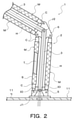
- FIG. 2 is an enlarged view showing the robot device 1.
- the robot device 1 shown in these drawings includes a robot arm (robot body) 2, a liquid supply device (fluid supply device) 10, and a control device 100 that controls the entire device.
- the robot arm 2 includes a plurality of (three in this embodiment) joints (pin joints) J1, J2, J3, a plurality of (three in this embodiment) arms (links) 3, and joints J1,
- a plurality of hydraulic actuators (fluid actuators) M as artificial muscles provided for each of J2 and J3, for example, an even number (four in this embodiment), and a hand portion as a gripping portion attached to the arm 3 on the tip side.
- the hand unit 4 is controlled by the control device 100 so as to grip the target object (hereinafter, referred to as “grasping target”). Further, the liquid supply device 10 is controlled by the control device 100 to supply and discharge hydraulic oil (working fluid) as a liquid to each hydraulic actuator M. As a result, the robot arm 2 can be driven hydraulically (hydraulic pressure) to move the hand portion 4 to a desired position.
- each hydraulic actuator M of the robot arm 2 is a so-called Macchiben type artificial muscle including a tube T that expands and contracts by the pressure of hydraulic oil and a braided sleeve S that covers the tube T. be.
- the tube T is formed in a cylindrical shape by an elastic material such as a rubber material having high oil resistance, and both ends of the tube T are sealed by a sealing member C.
- a hydraulic oil inlet / outlet IO is formed on the sealing member C on the base end side (liquid supply device 10 side, lower end side in FIG. 2) of the tube T.
- the braided sleeve S is formed in a cylindrical shape by knitting a plurality of cords oriented in a predetermined direction so as to intersect each other, and is retractable in the axial direction and the radial direction.
- a fiber cord, a high-strength fiber, a metal cord composed of ultrafine filaments, or the like can be adopted.
- the arm 3 on the most proximal end side (most liquid supply device 10 side) is rotatable by the support member 5 as a link via the joint J1. Be supported. Further, the two arms 3 are rotatably connected to each other via the joint J2 or J3. Further, the connecting member 6 is fixed to the tip ends (ends on the hand side) of the two arms 3 on the liquid supply device 10 side. As shown in the figure, the support member 5 rotatably supports the sealing member C on the proximal end side of the plurality (four) hydraulic actuators M corresponding to the joint J1 on the distal end side.
- each connecting member 6 rotatably supports the sealing member C on the tip end side (hand side) of the plurality (four) hydraulic actuators M corresponding to the joints J1 or J2 located on the proximal end side. .. Further, each connecting member 6 rotatably supports the sealing member C on the proximal end side of the plurality (four) hydraulic actuators M corresponding to the joints J2 or J3 located on the distal end side.
- the support member 5 rotatably supports the sealing member C on the proximal end side of the two hydraulic actuators M corresponding to the joint J1 via the first connecting shaft.
- the connecting member 6 of the arm 3 on the most proximal end side rotatably supports the sealing member C on the tip end side of the two hydraulic actuators M corresponding to the joint J1 via the second connecting shaft. ..
- the support member 5 can rotate the sealing member C on the proximal end side of the remaining two hydraulic actuators M corresponding to the joint J1 via the third connecting shaft extending in parallel with the first connecting shaft. Support.
- the connecting member 6 of the arm 3 on the most proximal end side extends the sealing member C on the tip end side of the remaining two hydraulic actuators M corresponding to the joint J1 in parallel with the second connecting shaft. It is rotatably supported via a connecting shaft.
- the connecting member 6 of the two arms 3 connected to each other via the joint J2 or J3 also has a plurality (four) corresponding to the joint J2 or J3 via the plurality of connecting shafts as described above.
- the corresponding sealing member C of the hydraulic actuator M is rotatably supported.
- two hydraulic actuators M are arranged in parallel with the corresponding arms 3 in the present embodiment on both sides of each arm 3 extending from the joint axis of the joints J1-J3 to the hand side (hand portion 4 side).
- the two hydraulic actuators M arranged on one side of each arm 3 constitute a first artificial muscle (one antagonist muscle) AM1 (see FIG. 3) corresponding to one joint J1, J2 or J3.
- the two hydraulic actuators M arranged on the other side of each arm 3 are the second artificial muscles (the other) corresponding to one joint J1, J2 or J3 paired with the first artificial muscle AM1.
- Antagonist muscle constitutes AM2 (see FIG. 3).
- the first and second artificial muscles AM1 and AM2 may each be composed of a single hydraulic actuator M, and the number of hydraulic actuators M constituting the first artificial muscle AM1 and the second The number of hydraulic actuators M constituting the artificial muscle AM2 may be different.
- the plurality (four) hydraulic actuators M provided for one joint J1, J2 or J3 have the same specifications.
- the specifications of the plurality of hydraulic actuators M corresponding to one joint J1, J2 or J3 do not necessarily have to be the same.
- the specifications of the hydraulic actuator M constituting the second artificial muscle AM2 may be different.
- each arm 3 is formed to be hollow, and a plurality of hoses H (see the broken line in FIG. 2) as a liquid supply pipe are arranged inside each arm 3.
- Each hose H is connected to an inlet / outlet IO formed in a sealing member C on the base end side of the corresponding hydraulic actuator M, and a liquid supply device is provided in the tube T of each hydraulic actuator M via the hose H.
- the hydraulic oil (hydraulic pressure) from 10 is supplied.
- the hydraulic pressure in the tube T of the two hydraulic actuators M constituting the first artificial muscle AM1 is paired with the first artificial muscle AM1.
- the hydraulic pressure in the tube T of the two hydraulic actuators M constituting the artificial muscle AM2 of 2 can be made different from each other.
- a force (rotational torque) is transmitted from the four hydraulic actuators M, that is, the paired (pair) of the first and second artificial muscles AM1 and AM2 to each arm 3 via the connecting member 6, and supported. It is possible to change the joint angle of the joints J1-J3 by rotating each arm 3 with respect to the member 5 or the arm 3 on the proximal end side.
- the two hydraulic actuators M constituting the first artificial muscle AM1 and the two hydraulic actuators M constituting the second artificial muscle AM2 paired with the first artificial muscle AM1 are
- the tube T is antagonistically driven by hydraulic pressure from the liquid supply device 10 with a state in which the tube T contracts in the axial direction by a predetermined amount (for example, about 10% of the natural length) as an initial state.
- the liquid supply device 10 of the robot device 1 has a tank 11 that defines a hydraulic oil storage section (liquid storage section) and a rotating shaft that extends the tank 11 in the vertical direction (one point in FIG. 1). Includes a base portion 12 that rotatably supports around the chain wire).
- the tank 11 is, for example, a cylinder whose upper end and lower end are closed, and can store hydraulic oil inside.
- the support member 5 of the robot arm 2 is fixed to the upper wall portion 11u of the tank 11 via a bolt or the like (not shown). That is, the robot arm 2 is supported by the tank 11 (upper wall portion 11u) of the liquid supply device 10.
- the base portion 12 is fixed to the installation location of the robot device 1 so as to be located below the robot arm 2 and the tank 11, or is mounted (fixed) on an automatic guided vehicle (AGV or AMR) (not shown). Further, the base portion 12 supports a rotation unit (not shown) that rotates the tank 11 around the rotation shaft. As a result, by operating the rotation unit, the robot arm 2 and the tank 11 can be integrally rotated around the rotation shaft.
- the rotating unit may be a swing motor driven by hydraulic pressure supplied from the liquid supply device 10, or may include an electric motor or the like.
- the liquid supply device 10 includes a pump 13 as a liquid supply source, a valve body (not shown) arranged in the tank 11, and a main pressure generation, in addition to the tank 11 and the base portion 12.
- the pump 13, the first and second linear solenoid valves 151, 152 and the first and second supply isolation valves 161, 162 are all controlled by the control device 100.
- the first and second linear solenoid valves 151 and 152 and the first and second supply cutoff valves 161, 162 are provided one by one for each of the joints J1, J2 and J3.
- the pump 13 is, for example, an electric pump, which sucks the hydraulic oil stored in the tank 11 and discharges it from the discharge port.
- the pump 13 includes a pump unit arranged in the tank 11 and a drive unit having an electric motor and a reduction gear mechanism and arranged in the tank 11 or outside the tank 11.
- the main pressure generation valve 14 drains (adjusts) a part of the hydraulic oil discharged from the pump 13 according to the signal pressure from the signal pressure generation valve (not shown) to generate the main pressure, and the main pressure is generated in the valve body. It is supplied to the oil passage (liquid passage) L0 formed in.
- the signal pressure generation valve of the main pressure generation valve 14 for example, a linear solenoid valve whose energization is controlled by the control device 100 is used.
- the first and second linear solenoid valves 151 and 152 include a solenoid portion 15e and a spool 15s whose energization is controlled by the control device 100, a spring SP for urging the spool 15s to the solenoid portion 15e side (upper side in FIG. 3), and the like. , Placed inside the valve body. Further, the first and second linear solenoid valves 151 and 152 have an input port 15i communicating with the oil passage L0 of the valve body, an output port 15o communicating with the input port 15i, and a feedback port 15f communicating with the output port 15o. And a drain port 15d that can communicate with the output port 15o.
- the first and second linear solenoid valves 151 and 152 are normally closed valves that open when a current is supplied to the solenoid portion 15e, and each solenoid portion 15e responds to the applied current.
- the spool 15s is moved in the axial direction.
- the thrust applied to the spool 15s from the solenoid portion 15e by supplying power to the solenoid portion 15e (coil), the urging force of the spring SP, and the hydraulic pressure supplied from the output port 15o to the feedback port 15f to the spool 5s.
- the hydraulic oil supplied from the main pressure generation valve 14 (pump 13) side to the input port 15i and flowing out from the output port 15o is regulated to a desired pressure. Can be done. Further, as shown in FIG. 3, the drain ports 15d of the first and second linear solenoid valves 151 and 152 communicate with the hydraulic oil storage portion in the tank 11 via the oil passage L3, respectively.
- the first and second supply cutoff valves 161, 162 are solenoid spool valves (solenoid valves) having the same structure as each other, and as shown in FIG. 3, the input port 16i, the first and second output ports 16oa, A sleeve having 16 obs, a spool (not shown) slidably (movably) arranged in the sleeve in the axial direction, an electromagnetic unit 16e controlled by the control device 100 to move the spool, and a spool electromagnetically. Each includes a spring (not shown) for urging the portion 16e side.
- the input port 16i of the first supply cutoff valve 161 is connected to the output port 15o of the first linear solenoid valve 151 via an oil passage formed in the valve body, and the input port 16i of the second supply cutoff valve 162 is a valve. It is connected to the output port 15o of the second linear solenoid valve 152 via an oil passage formed in the body.
- the first output port 16oa of the first supply isolation valve 161 is an inlet / outlet IO for hydraulic oil of one hydraulic actuator M (tube T) constituting the corresponding first artificial muscle AM1 via the oil passage L11.
- the second output port 16ob of the first supply isolation valve 161 is connected to the inlet / outlet IO of the hydraulic oil of the other hydraulic actuator M (tube T) constituting the first artificial muscle AM1 via the oil passage L12.
- the first output port 16oa of the second supply cutoff valve 162 is an inlet / outlet IO for hydraulic oil of one hydraulic actuator M (tube T) constituting the corresponding second artificial muscle AM2 via the oil passage L21.
- the second output port 16ob of the second supply cutoff valve 162 is connected to the inlet / outlet IO of the hydraulic oil of the other hydraulic actuator M (tube T) constituting the second artificial muscle AM2 via the oil passage L22. Will be done.
- the first and second supply cutoff valves 161, 162 are in a complete communication state, a first partial communication state, a second partial communication state, and a complete cutoff state according to the current supplied to the electromagnetic unit 16e. Form selectively.
- the first and second supply cutoff valves 161, 162 form a perfect communication state, both the input port 16i and the first and second output ports 16oa and 16ob communicate with each other.
- the first and second supply cutoff valves 161, 162 form the first partial communication state, the input port 16i and the second output port 16ob communicate with each other, and the input port 16i and the first output port 16oa communicate with each other. Is blocked.
- the input port 16i and the first output port 16oa communicate with each other, and the input port 16i and the second output port 16ob communicate with each other. Is blocked.
- the first and second supply cutoff valves 161, 162 form a complete cutoff state, the communication between the input port 16i and the first and second output ports 16oa and 16ob is cut off.
- the control device 100 of the robot device 1 includes a microcomputer including a CPU, ROM, RAM, an input / output interface, and various logic ICs (all of which are not shown).
- the control device 100 includes a main pressure sensor (not shown) that detects the pressure of the hydraulic oil in the oil passage L0 on the upstream side of the first and second linear solenoid valves 151 and 152, the first and second linear solenoid valves 151 and 152, and the first. 1.
- Input the detection value of a voltage sensor (not shown) that detects the voltage of the power supply of the second supply cutoff valves 161, 162.
- the control device 100 controls the duty of the pump 13 so that the hydraulic pressure in the oil passage L0 detected by the main pressure sensor becomes a target value, and is supplied to the electromagnetic part of the signal pressure generation valve of the main pressure generation valve 14. Control the current.
- control device 100 has a current from the first and second linear solenoid valves 151 and 152 to the first and second linear solenoid valves 151 and 152 so that the hydraulic pressure corresponding to the request is supplied to each hydraulic actuator M.
- a command value is set, and the current supplied to each solenoid unit 15e is controlled based on the current command value.
- the control device 100 basically supplies a current to each solenoid unit 16e so that the first and second supply isolation valves 161, 162 form the above-mentioned complete communication state while the robot device 1 is operated. To control.
- control device 100 includes a current detecting unit that detects a current flowing through the solenoid portion 15e of the first linear solenoid valve 151 and a current detecting unit that detects a current flowing through the solenoid portion 15e of the second linear solenoid valve 152. (Neither is shown), the current detected by each current detector is monitored.
- control device 100 first and second so as to form the first partial communication state or the second partial communication state according to the detection value from the pressure sensor (not shown) that detects the hydraulic pressure in each hydraulic actuator M. Controls the applicable supply shutoff valves 161, 162. As a result, when hydraulic oil flows out from one of the two hydraulic actuators M corresponding to any of the first and second linear solenoid valves 151 and 152 due to damage or the like, the other of the two hydraulic actuators M is affected. It is possible to continuously supply the hydraulic oil to suppress the disturbance of the behavior of the robot arm 2 and to satisfactorily suppress the further outflow of the hydraulic oil from the damaged hydraulic actuator M.
- the first or second linear solenoid valves 151, 152 correspond to the corresponding ones. It is possible to cut off the supply of hydraulic oil to the two hydraulic actuators M, or to regulate the outflow of hydraulic oil from the two hydraulic actuators M to suppress the occurrence of unintended operation of the robot arm 2. can.
- FIG. 4 is a block diagram showing a control unit of the first and second linear solenoid valves 151 and 152 in the above-mentioned control device 100.
- the control device 100 is a target position setting unit constructed by at least one of hardware such as a CPU, ROM, and RAM of a computer and software such as a control program installed in the computer.
- 101 current position derivation unit 102, target torque setting unit 105 including torque calculation unit 103 and gravity compensation unit 104, target rigidity setting unit 106, contraction rate setting unit 107, contraction force calculation unit 108, and target pressure derivation.
- a target pressure setting unit 110 including a unit 109, a current command value setting unit 111, and a valve drive unit 112 are included.
- the target position setting unit 101 is a target that is the final target position of the hand unit 4 based on the position of the gripping target of the hand unit 4 and the target speed and target acceleration of the hand unit 4 during movement given by the user.
- the arrival position (three-dimensional coordinates) and the trajectory from the initial position of the hand unit 4 to the target arrival position and including a plurality of target positions, that is, transit positions (three-dimensional coordinates) are set.
- the current position derivation unit 102 is a hand unit 4 based on the joint angles ⁇ 1, ⁇ 2, ⁇ 3 of the joints J1-J3 of the robot arm 2 and the specifications (dimensions, etc. of the arm 3) of the robot arm 2 (robot device 1).
- the current position (three-dimensional coordinates) of (predetermined reference point) is derived.
- the joint angles ⁇ 1- ⁇ 3 of the joints J1-J3 are detected by any of the corresponding joint angle sensors 7 provided on the robot arm 2.
- the torque calculation unit 103 of the target torque setting unit 105 has two arms 3 (arm 3 and a support) connected via the joint Ji so that the hand unit 4 moves from the current position to the target position for each joint J1-J3.
- the joint torque Tj (i) that relatively rotates the member 5) is calculated.
- the gravity compensating unit 104 of the target torque setting unit 105 determines the robot arm 2 for each joint J1-J3 based on the joint angle ⁇ 1- ⁇ 3 and the specifications of the robot arm 2 (robot device 1) (dimensions of the arm 3, etc.).
- the gravity compensation torque Tc (i) required to maintain the posture of is calculated.
- the target torque setting unit 105 is for relatively rotating the sum of the joint torque Tj (i) and the gravity compensation torque Tc (i) so that the two arms 3 and the like connected via the joint Ji are relatively rotated.
- the target torque Ttag (i) which is the target value (target driving force) of the joint torque Tj (i) is set.
- the target rigidity setting unit 106 has the rigidity that the joint Ji should have for each joint J1-J3, that is, two arms 3 connected via the joint Ji, etc., at least based on the target position of the robot device 1, that is, the hand unit 4.
- the contraction rate setting unit 107 of the target pressure setting unit 110 is the first artificial artificial muscle corresponding to the joint Ji based on the joint angle ⁇ i of the joint Ji according to the current position of the hand unit 4 for each joint J1-J3.
- the contraction rate Cr1 (i) of the two hydraulic actuators M constituting the muscle AM1 and the contraction rate Cr2 (i) of the two hydraulic actuators M constituting the second artificial muscle AM2 corresponding to the joint Ji are obtained.
- the contraction force calculation unit 108 of the target pressure setting unit 110 has a target torque Ttag (i) set by the target torque setting unit 105 and a target rigidity R (target rigidity R) set by the target rigidity setting unit 106 for each joint J1-J3. Based on i), a plurality of (pair) hydraulic actuators corresponding to the joint Ji when the two arms 3 and the like connected via the joint Ji are relatively rotated by the target torque Ttag (i). The contraction forces Fc1 (i) and Fc2 (i) required for M are calculated.
- the contraction force Fc1 (i) is a force to be generated by the contraction of the tubes T of the two hydraulic actuators M constituting the first artificial muscle AM1 corresponding to each joint Ji
- the contraction force Fc2 (i) is It is a force to be generated by the contraction of the tube T of the two hydraulic actuators M constituting the second artificial muscle AM2 corresponding to each joint Ji.
- the target pressure derivation unit 109 of the target pressure setting unit 110 has the contraction rate Cr1 (i) and the contraction force set by the contraction rate setting unit 107 from the static characteristics of the hydraulic actuator M as an artificial muscle for each joint J1-J3.
- the pressure corresponding to the contraction force Fc1 (i) calculated by the calculation unit 108 is derived and set to the target pressure Ptag1 (i) of the two hydraulic actuators M constituting the first artificial muscle AM1.
- the target pressure derivation unit 109 has a contraction rate Cr2 (i) set by the contraction rate setting unit 107 and a contraction force Fc2 (i) calculated by the contraction force calculation unit 108 from the static characteristics for each joint J1-J3.
- the target pressure Ptag2 (i) of the two hydraulic actuators M constituting the second artificial muscle AM2 by deriving the pressure corresponding to the above.
- the current command value setting unit 111 sets the target pressures Ptag1 (i) and Ptag2 (i) set by the target pressure setting unit 110 to the solenoid units 15e of the first and second linear solenoid valves 151 and 152 (current command value setting unit 111). Convert directly to the target current).
- the valve drive unit 112 sets a target voltage by feed-forward control (or feed-forward control and feedback control) so that the current detected by the above-mentioned current detection unit (not shown) matches the current command value, and sets the target voltage. Convert to PWM signal.
- valve drive unit 112 controls switching of a switching element (transistor) (not shown) based on the PWM signal to apply a current to the solenoid units 15e of the first and second linear solenoid valves 151 and 152.
- a switching element transistor
- the first and second linear solenoid valves 151 and 152 are controlled to generate hydraulic pressure according to the target pressure Ptag1 (i) or Ptag2 (i).
- control procedure of the above-mentioned robot device 1 will be described with reference to FIGS. 5 to 10.
- control procedure of the robot device 1 will be described by taking as an example a case where the hand portion 4 of the robot device 1 is moved to the gripping target and the hand portion 4 grips and transfers the gripping target.
- the hand of the robot arm 2 that is, the hand portion 4, and the gripping target are connected via a virtual spring and a damper, and the virtual spring and the damper are generated.
- the tensile force Ft (f x , f y , f z ) due to the virtual spring and damper is the target position (xd (t), of the hand portion 4 (predetermined reference point).
- the gripping target is pulled by the virtual spring and damper according to the above equation (1).
- the position (contact position) of the gripping object (x o , yo , z o ) and the gains K px , K py , K pz can be expressed as the following equation (2).
- the routine of FIG. 5 is executed by the target position setting unit 101 of the control device 100, and the final of the hand unit 4 is executed.
- a target arrival position (x r , y r , z r ) and a target trajectory of the hand unit 4 from the initial position to the target arrival position (x r , y r , z r ) are set.
- the target position setting unit 101 of the control device 100 determines the position (x o , yo , z o ) of the gripping target and the target speed of the hand unit 4 given by the user during movement.
- the position (x o , yo , z o ) of the gripping object may be input to the control device 100 by the user of the robot device 1 if it is known in advance, and the camera may be input to the control device 100 before the operation of the robot arm 2 is started. It may be derived from the data acquired by the above.
- the target position setting unit 101 reaches the target of the hand unit 4 in which a predetermined pressing force Fp is applied from the hand unit 4 to the gripping object after the contact between the hand unit 4 and the gripping object according to the above equation (2).
- the position (x r , y r , z r ) is set (step S2).
- the pressing force Fp (f px , f py , f pz ) in the equation (2) is based on the specifications such as the material, strength, and size of the gripping object, without destroying the gripping object.
- the target position setting unit 101 is based on the target speed and target acceleration of the hand unit 4 acquired in step S1 and the target arrival position (x r , y r , z r ) set in step S2.
- a target trajectory of the hand unit 4 including a predetermined number (plural) target positions, that is, transit positions (three-dimensional coordinates) is set (step S3), and the routine of FIG. 5 is terminated.
- the target arrival position and the target trajectory are set according to the transfer destination (the mounting surface of the grip target) of the grip target.
- the routine of FIG. 5 is executed again by the target position setting unit 101.
- the target position setting unit 101 is placed on the mounting surface (target) from the hand unit 4 via the gripping target after the contact between the gripping target (hand) gripped by the hand unit 4 and the mounting surface (target).
- the target arrival position (x r , y r , z r ) of the hand unit 4 to which the predetermined pressing force Fp is applied is set.
- FIG. 6 is a flowchart illustrating a robot arm control routine executed by the control device 100 after the target arrival position and the target trajectory are set. After the routine of FIG. 5 is completed, the routine of FIG. 6 is repeatedly executed by the control device 100 at predetermined time (for example, about 10 ms) in response to an execution instruction by the user.
- predetermined time for example, about 10 ms
- the torque calculation unit 103 (target torque setting unit 105) and the target rigidity setting unit 106 of the control device 100 each acquire the target position set by the target position setting unit 101 (step S10). ..
- the target position acquired in step S10 is the first target position in the target trajectory or the target position acquired at the time of the previous execution of the routine of FIG.
- the current position derivation unit 102 and the gravity compensation unit 104 of the control device 100 acquire the joint angles ⁇ 1- ⁇ 3 of the joints J1-J3 acquired by the plurality of joint angle sensors 7 (step S20).
- the current position deriving unit 102 derives the current position (three-dimensional coordinates) of the hand unit 4 based on the acquired joint angle ⁇ 1- ⁇ 3 and the specifications of the robot arm 2 (robot device 1) (step S30). The derived current position is given to the torque calculation unit 103.
- the torque calculation unit 103 (target torque setting unit 105) of the control device 100 determines whether or not the current position of the hand unit 4 has changed from the previous position (whether or not the hand unit 4 has moved) (step). S40). When the torque calculation unit 103 determines that the current position of the hand unit 4 has changed from the previous position (step S40: YES), it further determines whether or not the current position substantially matches the target position. Determination (step S50). When it is determined that the current position substantially matches the target position (step S50: YES), the torque calculation unit 103 acquires the target position next to the target position acquired in step S10 (step S60). ..
- the next target position is also given to the target rigidity setting unit 106, and the target rigidity setting unit 106 sets the target rigidity R (i) of each joint Ji based on the acquired target position and the like. Further, if the current position of the hand unit 4 does not substantially match the target position, the process of step S60 is skipped.
- FIG. 7 is a flowchart illustrating a procedure for setting the target torque Ttag (i) by the target torque setting unit 105 in step S70.
- the torque calculation unit 103 of the target torque setting unit 105 first sets the above-mentioned gains K px , K py and K pz based on the target position of the hand unit 4 acquired in step S10. (Step S700).
- step S700 the torque calculation unit 103 has gains K px , K py and K pz until the target position acquired in step S10 reaches a predetermined target position (for example, a position where the hand unit 4 starts decelerating). After each is set to a predetermined normal value and the target position acquired in step S10 becomes the predetermined target position, each of the gains K px , K py and K pz is smaller than the above normal value. Set to a value.
- the torque calculation unit 103 describes the above-mentioned virtual from the above equation (1) based on the target position of the hand unit 4 acquired in step S10 and the current position of the hand unit 4 acquired in step S30.
- the movement of the robot arm 2 (each joint Ji) can be made smoother.
- the torque calculation unit 103 acquires a separately set human feeling flag (step S720), and determines whether or not the human feeling flag is turned off (step S730).
- the human sensor is turned on or off by the control device 100 based on a signal from at least one motion sensor 8 (see FIG. 1) arranged at the installation location of the robot device 1 or an automatic guided vehicle. .. That is, when the presence of a person is not detected by the at least one motion sensor 8, the control device 100 turns off the human sensor, and when the presence of a person is detected by at least one motion sensor 8, the control device 100 turns off the human sensor. Turn on the motion flag.
- step S730: YES When the torque calculation unit 103 determines that the human feeling flag is turned off (step S730: YES), the torque calculation unit 103 sets the first force (vector) Fu1 to the upper limit value Fu of the tensile force Ft (step S740). Further, when the torque calculation unit 103 determines that the human feeling flag is turned on (step S730: NO), the torque calculation unit 103 sets the second force (vector) Fu2, which is smaller than the first force Fu1, to the upper limit of the tensile force Ft. Set to the value Fu (step S745). After the process of step S740 or S745, the torque calculation unit 103 sets (resets) the smaller of the tensile force Ft and the upper limit value Fu set in step S710 to the tensile force Ft (step S750).
- the torque calculation unit 103 has a hand unit 4 for each joint J1-J3 from the tensile force Ft set in step S750 and the Jacobian determinant shown in the following equation (5).
- the target torque setting unit 105 sums the joint torque Tj (i) calculated by the torque calculation unit 103 as described above and the gravity compensation torque Tc (i) separately calculated by the gravity compensation unit 104.
- the target torque Ttag (1) -Ttag (3) for relatively rotating the two arms 3 and the like is set (step S770).
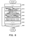
- FIG. 8 is a flowchart illustrating the setting procedure of the target pressures Ptag1 (i) and Ptag2 (i) by the target pressure setting unit 110 in step S80.
- the target pressure setting unit 110 first sets the variable i, that is, the joint number to the value 1 (step S800).
- the contraction force calculation unit 108 of the target pressure setting unit 110 has a target torque Ttag (i) for the joint Ji set by the target torque setting unit 105 and a target rigidity of the joint Ji set by the target rigidity setting unit 106.
- Acquire R (i) step S810).
- the contraction rate setting unit 107 of the target pressure setting unit 110 acquires the current joint angle ⁇ i of the joint Ji detected by the corresponding joint angle sensor 7.
- the contraction rate setting unit 107 of the target pressure setting unit 110 that has acquired the joint angle ⁇ i has the contraction rate Cr1 (i) of the two hydraulic actuators M constituting the first artificial muscle AM1 corresponding to the joint Ji, and the joint.
- the contraction rate Cr2 (i) of the two hydraulic actuators M constituting the second artificial muscle AM2 corresponding to Ji is set (step S820).
- the contraction rate setting unit 107 configures the first artificial muscle AM1 based on the joint angle ⁇ i of the joint Ji, the specifications of the robot arm 2 (robot device 1) (dimensions of the arm 3 and the like), and the like.
- the contraction rate Cr1 (i) of the two hydraulic actuators M and the contraction rate Cr2 (i) of the two hydraulic actuators M constituting the second artificial muscle AM2 are derived and set.
- the contraction force calculation unit 108 of the target pressure setting unit 110 is the first artificial muscle corresponding to the joint Ji based on the target torque Ttag (i) acquired in step S810 and the target rigidity R (i) of the joint Ji.
- the contraction force (tensile force) Fc1 (i) required for the two hydraulic actuators M constituting the muscle AM1 and the two hydraulic actuators M constituting the second artificial muscle AM2 corresponding to the joint Ji are required.
- the contraction force (tensile force) Fc2 (i) to be generated is calculated (step S830).
- step S830 the contraction force calculation unit 108 solves the simultaneous equations obtained from these two relational expressions, and thereby, the contraction force Fc1 corresponding to the target torque Ttag (i) and the target rigidity R (i) of the joint Ji. (I), Fc2 (i) is calculated.
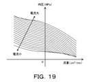
- the target pressure derivation unit 109 of the target pressure setting unit 110 has a pressure corresponding to the contraction rate Cr1 (i) and the contraction force Fc1 (i) from the target pressure setting map illustrated in FIG. Is appropriately linearly interpolated and set to the target pressure Ptag1 (i) of the two hydraulic actuators M constituting the first artificial muscle AM1 (step S840). Further, in step S840, the target pressure derivation unit 109 derives the pressure corresponding to the contraction rate Cr2 (i) and the contraction force Fc2 (i) from the target pressure setting map to form the second artificial muscle AM2. The target pressure Ptag2 (i) of the two hydraulic actuators M is set.
- the target pressure setting map of FIG. 9 shows the static characteristics of the hydraulic actuator M as an artificial muscle, and the contraction rate of the tube T and the tube T are generated for each hydraulic pressure supplied to the hydraulic actuator M. It was created through experiments and analysis in advance so as to define the relationship with the contractile force. In this way, the pressure corresponding to the contraction rates Cr1 (i) and Cr2 (i) and the contraction forces Fc1 (i) and Fc2 (i) of the tube T is set to the target pressures Ptag1 (i) and Ptag2 (i). Therefore, the target pressures Ptag1 (i) and Ptag2 (i) can be set accurately according to the request to the robot arm 2.
- the target pressure setting unit 110 increments the variable i (step S850) and determines whether or not the variable i is a value N + 1 or more. Determination (step S860).
- the target pressure setting unit 110 determines that the variable i is less than the value N + 1 (step S860: NO)
- the target pressure setting unit 110 re-executes the process of the above steps S810-S860.
- the target pressure setting unit 110 determines that the variable i is the value N + 1 or more (step S860: YES), as shown in FIG.
- the current command value setting unit 111 of the control device 100 displays a map or the like (not shown). Using, each of the target pressures Ptag1 (i) and Ptag2 (i) of each joint Ji is directly converted into a current command value (step S90).
- the current command value derived by the current command value setting unit 111 is given to the valve drive unit 112 of the control device 100, and the valve drive unit 112 has a plurality of first and second linear solenoids, respectively, based on the current command.
- the valves 151 and 152 are controlled (PWM control) (step S100).
- the current command value to the liquid supply device 10 according to the target torque Ttag (i) is easily and quickly set, and the first and second linears of the liquid supply device 10 are controlled based on the current command value.
- Each of the solenoid valves 151 and 152 produces a hydraulic pressure corresponding to the corresponding target pressure Ptag1 (i) or Ptag2 (i). Further, the hydraulic oil regulated by the first and second linear solenoid valves 151 and 152 is supplied to the tube T of the corresponding hydraulic actuator M via the first and second supply cutoff valves 161, 162.
- the flow rate control valve adjusts the flow rate of the hydraulic oil and supplies it into the tube T, or the hydraulic pressure supplied to the tube T is detected by the pressure sensor so that the actual hydraulic pressure matches the target pressure.
- the hydraulic pressure supplied to each tube T within a short time from the setting of the target pressures Ptag1 (i) and Ptag2 (i) is applied to the target pressures Ptag1 (i) and Ptag2 (i), as compared with the case of feedback control. It is possible to substantially match i) so that the actual shrinkage rate of each tube T can be made to follow the required value with good responsiveness and high accuracy.
- the control device 100 temporarily terminates the routine of FIG. 6, and executes the process of step S10 and subsequent steps again according to the arrival of the next execution timing.
- step S40 of FIG. 6 determines that the current position is from the previous position. It is determined whether or not a predetermined relatively short time (predetermined time) has elapsed since the change substantially stopped (step S55). When it is determined that the predetermined time has not elapsed since the current position does not substantially change (step S55: NO), the torque calculation unit 103 determines, for example, the difference between the target arrival position and the current position and the said. The target position of the hand unit 4 is set based on the predetermined time (step S65).
- predetermined time a predetermined relatively short time
- step S65 for example, the torque calculation unit 103 sets the target position so that the target position coincides with the target arrival position shortly before the predetermined time elapses after the current position does not substantially change. And change at a constant rate.
- the processes after step S70 are executed. Further, the target position set in step S65 is also given to the target rigidity setting unit 106, and the target rigidity setting unit 106 sets the target rigidity R (i) of each joint Ji based on the acquired target position and the like. Set.
- step S55 the control device 100 ends the routine of FIG. 6 and causes the hand unit 4 to grip the gripping object. Executes the hand control routine of. Further, the target position setting unit 101 of the control device 100 executes the routine of FIG. 5 until the gripping target is gripped by the hand unit 4, and sets the target arrival position and the target trajectory according to the mounting position of the gripping target. Set. Further, when the gripping target is gripped by the hand unit 4 and the hand control routine is completed, the control device 100 re-executes the routine of FIG. 6 in order to convey the gripping target to the mounting position by the robot arm 2.
- the target position of the hand unit 4 may be set to change at a predetermined rate from the current position to the target arrival position, and the target position is one to the target arrival position.
- the routine of FIG. 6 may be terminated when a predetermined time has elapsed.
- the target position setting unit 101 of the control device 100 of the robot device 1 mounts the gripping target (hand) gripped by the hand portion 4 of the robot device 1 or the hand portion 4 on the gripping target or the gripping target.
- the gripping object or mounting from the hand unit 4 A target reaching position of the hand portion 4 to which a predetermined pressing force Fp is applied to the surface is set (step S2 in FIG. 5). That is, as shown in FIG. 10, the target position setting unit 101 sets a position slightly ahead of the position of the pinching target or the like to the target arrival position of the hand unit 4.
- the control device 100 has a target torque Ttag (i) for each joint Ji of the robot arm 2 based on the target position included in the target trajectory set based on the target arrival position and the current position of the hand unit 4. (Step S70 in FIG. 6), and the target pressures Ptag1 (i) and Ptag2 (i) of the plurality of hydraulic actuators M corresponding to each joint Ji are set based on the target torque Ttag (i) (FIG. 6). Step S80 of 6. Further, the control device 100 controls the first and second linear solenoid valves 151 and 152 of the liquid supply device 10 based on the target pressures Ptag1 (i) and Ptag2 (i) (steps S90-S100 in FIG. 6).
- the above-mentioned pushing is performed in consideration of variations in the position of the gripping object or the like so that the hand portion 4 or the gripping object (hand) is brought into contact with the gripping object or the mounting surface (object) without destroying the gripping object.
- the pressure Fp is set, the moving speed of the hand unit 4 is reduced when the hand unit 4 or the like approaches the gripping object to some extent, or the sensor detects the contact between the hand unit 4 or the like and the gripping object or the like. It is possible to bring the hand portion 4 or the like of the robot device 1 into contact with the gripping object or the like without causing the trouble.
- each hydraulic actuator M can be responsively and highly responsive to a request without using a sensor for detecting the hydraulic pressure supplied to each hydraulic actuator M as an artificial muscle. It is possible to operate with high accuracy.
- the target position setting unit (target arrival position setting unit and target trajectory setting unit) 101 of the control device 100 sets the target arrival position, and is based on the target arrival position, the target speed of the hand unit 4, and the target acceleration.
- the target trajectory of the hand unit 4 including the plurality of target positions is set (steps S1-S3 in FIG. 5).
- the target torque setting unit 105 calculates the tensile force (driving force) Ft for moving the hand unit (hand) 4 of the robot device 1 from the current position to the target position, and determines the joint Ji based on the tensile force Ft.
- the target torque Ttag (i) for relatively rotating the two arms (links) 3 and the like connected via the beam is set (step S70 in FIG.
- the target pressure setting unit 110 sets the target pressures Ptag1 (i) and Ptag2 (i) based on the target torque Ttag (i) (step S80 in FIG. 6). Further, the current command value setting unit 111 directly converts the target pressures Ptag1 (i) and Ptag2 (i) into current command values to the first and second linear solenoid valves 151 and 152 of the liquid supply device 10 (FIG. 6). Step S90).
- the current command values from the target torque Ttag (i) to the first and second linear solenoid valves 151 and 152 are easily and quickly set to respond to the hydraulic pressure supplied to each hydraulic actuator M as an artificial muscle.
- the hand portion 4 of the robot device 1 is moved so as to follow a target trajectory by a plurality of hydraulic actuators M so that the hand portion 4 is brought into contact with the gripping target, or the gripping target is brought into contact with the mounting surface. It is possible to make it.
- the target position setting unit 101 may set only the target arrival position without setting the target trajectory. In this case, the target torque setting unit 105 determines the difference between the target arrival position and the current position.
- the target Ttag (i) may be set based on the above.
- the position of the gripping object cannot be accurately acquired at the start of starting the robot device 1, the position of the gripping object acquired by a camera or the like at predetermined time intervals after the hand unit 4 approaches the gripping object.
- the target arrival position may be derived from the predetermined time intervals.
- the torque calculation unit 103 of the target torque setting unit 105 calculates the tensile force Ft so as not to exceed a predetermined upper limit value Fu (Fu1 or Fu2) (step S750 in FIG. 7).
- the torque calculation unit 103 has a person around the robot device 1 (for example, an area including an operating range of the robot arm 2 such as a room where the robot device 1 is arranged or the inside of a fence).
- the upper limit value Fu is made smaller than when there is no person around the robot device 1 (FIG. 7). Step S720-S745).
- the target position setting unit (target trajectory setting unit) 101 limits the separately given target acceleration so as not to exceed a predetermined upper limit acceleration, and the hand unit at predetermined time intervals. It may set the target position of 4.
- the target position setting unit 101 may be configured so that when there is a person around the robot device 1, the upper limit acceleration is smaller than when there is no person around the robot device 1.
- the torque calculation unit 103 of the target torque setting unit 105 includes a relational expression of feedback control including a proportional term obtained by multiplying the difference between the target position and the current position by the gains K px , K py , and K pz .
- the tensile force Ft is calculated according to 1), and the gains K px , K py , and K pz are changed according to the target position of the hand portion 4 (step S700 in FIG. 7). This makes it possible to change the followability of the hand unit 4 to the target trajectory and the degree of increase of the pressing force Fp applied from the hand unit 4 or the like to the gripping object or the like after contact.
- the gain K px , K py , and K pz are increased, the followability of the hand portion 4 to the target trajectory is improved, while after the contact between the hand portion 4 and the gripping target or between the gripping target and the mounting surface.
- the increasing gradient of the pressing force Fp after the contact is increased.
- the gains K px , K py , and K pz are reduced, the followability of the hand portion 4 to the target trajectory becomes gentle, but after the contact between the hand portion 4 and the gripping target or on the gripping target.
- the increasing gradient of the pressing force Fp after contact with the mounting surface can be reduced.
- the gains K px , K py , and K pz are made smaller than the previous values when the hand portion 4 approaches the gripping object or the mounting surface to some extent, the responsiveness of the robot device 1 is achieved. And safety can be further improved.
- the gains K px , K py , and K pz may be changed according to the current position of the hand unit 4.
- the torque calculation unit 103 of the target torque setting unit 105 calculates the joint torque Tj (i) for moving the hand unit 4 of the robot device 1 from the current position to the target position for each joint J1-J3. do. Further, the gravity compensating unit 104 of the target torque setting unit 105 calculates the gravity compensating torque Tc (i) required to maintain the posture of the robot arm 2 (robot device 1) for each of the joints J1-J3. Further, the target torque setting unit 105 is for relatively rotating the sum of the joint torque Tj (i) and the gravity compensating torque Tc (i) to rotate the two arms 3 and the like connected via the joint Ji.
- the target torque Ttag (i) is set (step S70 in FIG. 6 and step S770 in FIG. 7). This makes it possible to move the hand portion 4 of the robot device 1 by the plurality of hydraulic actuators M while suppressing the disturbance of the behavior of the robot arm 2 (robot device 1).
- control device 100 corresponds to the target rigidity setting unit 106 that sets the target rigidity R (i) of each joint Ji based on at least the target position of the hand unit 4 of the robot device 1 and the current position of the robot device 1.
- the contraction rate setting unit 107 that sets the contraction rates Cr1 (i) and Cr2 (i) of each hydraulic actuator M based on each joint angle ⁇ i, and the target torque Ttag (i) and the target rigidity R (i).
- the contraction force calculation unit 108 that calculates the contraction forces Fc1 (i) and Fc2 (i) required for the plurality of (pair) hydraulic actuators M corresponding to the joint Ji, and the contraction rate Cr1 (i) from the target pressure setting map.
- the pressure corresponding to the contraction force Fc1 (i) and the contraction rate Cr2 (i) and the pressure corresponding to the contraction force Fc2 (i) are derived and set to the target pressures Ptag1 (i) and Ptag2 (i).
- a target pressure derivation unit 109 the target pressures Ptag1 (i) and Ptag2 (i) are set accurately according to the requirements of each hydraulic actuator M as an artificial muscle, and the robot device 1 including the plurality of hydraulic actuators M is responsively stable. It becomes possible to operate.
- 11 and 12 are flowcharts illustrating a target rigidity setting routine executed by the target rigidity setting unit 106 of the control device 100.
- the target rigidity setting routine shown in these drawings is repeatedly executed by the target rigidity setting unit 106 at predetermined time intervals (for example, about 10 ms) in parallel with the robot arm control routine of FIG.
- the target rigidity setting unit 106 uses the target arrival position of the hand unit 4, the target position of the hand unit 4 used in the robot arm control routine of FIG. 6 at that time, and the above-mentioned person. Acquire the feeling flag (step S600). Next, the target rigidity setting unit 106 determines whether or not the human feeling flag is turned off (step S605), and when it is determined that the human feeling flag is turned off (step S605: YES), the hand unit 4 determines. It is determined whether or not the gripping object is gripped (step S610).
- the target rigidity setting unit 106 is concerned based on the target arrival position and the target position of the hand unit 4 acquired in step S600. It is determined whether or not the hand portion 4 is located substantially directly above the gripping target (step S615).
- the target rigidity setting unit 106 determines that the hand unit 4 is not located substantially directly above the gripping object (step S615: NO)
- the target rigidity value Rm is predetermined for each of the joints J1-J3.
- (I) is set to the target rigidity R (i) of each joint Ji (step S620), and the target rigidity setting routine is temporarily terminated.
- the rigidity value Rm (i) may be set so as to be able to suppress the vibration of the robot arm 2 while ensuring the contraction force (torque) of each hydraulic actuator M.
- the target rigidity setting unit 106 has a relatively low rigidity predetermined for each of the joints J1-J3.
- the value Rl (i) is set to the target stiffness R (i) of each joint Ji (step S640), and the target stiffness setting routine is temporarily terminated.
- the maximum contractile force generated by the two hydraulic actuators M constituting the first artificial muscle AM1 corresponding to the joint Ji and the two hydraulic pressures constituting the second artificial muscle AM2 corresponding to the joint Ji If the maximum contraction force generated by the actuator M is the same and the maximum contraction force is "Fmax", the maximum torque Tmax that can be applied to the joint Ji from the four hydraulic actuators M is
- At this time, the rigidity R of the joint Ji is R Fmax.
- the target rigidity setting unit 106 determines that the gripping target is gripped by the hand unit 4 (step S610: YES)
- the target rigidity setting unit 106 is based on the target arrival position and the target position of the hand unit 4 acquired in step S600.
- the target rigidity setting unit 106 concerned for example, based on the target arrival position and the target position of the hand unit 4. It is determined whether or not the hand portion 4 is moving toward the mounting position (step S630).
- the target rigidity setting unit 106 determines that the hand unit 4 is moving toward the mounting position (step S630: YES), for example, the hand unit is based on the target arrival position and the target position of the hand unit 4. It is determined whether or not 4 has reached a position separated from the mounting position by a relatively short predetermined distance (step S635). When it is determined that the hand unit 4 has reached a position separated by a predetermined distance from the mounting position (step S635: YES), the target rigidity setting unit 106 sets the above-mentioned relatively low rigidity value Rl (i) to each joint. The target rigidity R (i) of Ji is set (step S640), and the target rigidity setting routine is temporarily terminated. This makes it possible for the joints J1-J3 to satisfactorily absorb the impact when the gripping object gripped by the hand portion 4 is placed on the mounting surface.
- the target rigidity setting unit 106 determines each of the joints J1-J3 in advance.
- the relatively high rigidity value Rh (i) obtained is set to the target rigidity R (i) of each joint Ji (step S645), and the target rigidity setting routine is temporarily terminated.
- the target rigidity setting unit 106 is predetermined for each of the joints J1-J3.
- the relatively high rigidity value Rh (i) obtained is set to the target rigidity R (i) of each joint Ji (step S645), and the target rigidity setting routine is temporarily terminated. This makes it possible to satisfactorily absorb the vibration of the robot arm 2 when the gripping object gripped by the hand portion 4 is lifted or lowered toward the mounting position.
- the contraction force generated by the two hydraulic actuators M constituting the first artificial muscle AM1 corresponding to the joint Ji and the two hydraulic actuators M constituting the second artificial muscle AM2 corresponding to the joint Ji are the maximum contraction force Fmax.
- step S625 when it is determined that the hand unit 4 is not located substantially directly above the mounting position (step S625: NO), the target rigidity setting unit 106 is the hand unit 4 at that time as shown in FIG.
- the target acceleration of (step S650) is acquired, and it is determined whether or not the hand unit 4 accelerates or decelerates based on the target acceleration (step S660).
- step S660 When it is determined that the hand unit 4 moves at a constant speed (step S660: NO), the target rigidity setting unit 106 sets the above-mentioned medium rigidity value Rm (i) to the target rigidity R (i) of each joint Ji. (Step S675), the target rigidity setting routine is temporarily terminated.
- the target rigidity setting unit 106 determines whether or not the hand unit 4 accelerates from the target acceleration acquired in step S650. (Step S670).
- the target rigidity setting unit 106 sets the above-mentioned relatively low rigidity value Rl (i) to the target rigidity R (i) of each joint Ji (step). S680), the target rigidity setting routine is temporarily terminated.
- the target rigidity setting unit 106 sets the above-mentioned relatively high rigidity value Rh (i) to the target rigidity R (i) of each joint Ji. (Step S690), the target rigidity setting routine is temporarily terminated. This makes it possible to satisfactorily absorb the vibration of the robot arm 2 when the hand portion 4 that grips the gripping object decelerates.
- the target rigidity setting unit 106 determines that the human feeling flag is turned on (step S605: NO)
- the above-mentioned relatively low rigidity value Rl (i) is set to the target rigidity R (i) of each joint Ji. (Step S640), and the target rigidity setting routine is temporarily terminated.
- the robot device 1 operates by receiving a supply of a plurality of joints Ji and hydraulic oil (liquid), and relatively has two arms (links) 3 and the like connected via the joints Ji.
- a plurality of hydraulic actuators (artificial muscles) M to be rotated to, a plurality of first linear solenoid valves 151 and a plurality of second linear solenoid valves for adjusting the pressure of hydraulic oil supplied to the plurality of hydraulic actuators M.
- the 152 includes a control device 100 for controlling the first and second linear solenoid valves 151 and 152.
- the control device 100 sets a target torque setting unit 105 for setting a target torque Ttag (i) for relatively rotating the two arms 3 and the like, and a target rigidity R (i) for each joint Ji.
- the target rigidity setting unit 106 is included. Then, the control device 100 determines the hydraulic target pressures Ptag1 (i) and Ptag2 (i), which are supplied to the plurality of hydraulic actuators M corresponding to the joint Ji based on the target torque Ttag (i) and the target rigidity R (i). i) is set, and the first and second linear solenoid valves 151 and 152 are controlled based on the target pressures Ptag1 (i) and Ptag2 (i) (steps S70-S100 in FIG. 6 and steps S800- in FIG. 8). 860).
- the force to be output from the hydraulic actuator M as an artificial muscle in order to relatively rotate the two arms 3 and the like relatively rotates the two arms 3 and the like connected via the joint Ji. It can be determined from the target torque Ttag (i) for making the target torque Ttag (i) and the target rigidity R (i) of the joint Ji connecting the two arms 3 and the like.
- the target hydraulic pressures Ptag1 (i) and Ptag2 (i) to the hydraulic actuator M are set based on the target torque Ttag (i) and the target rigidity R (i), and the target pressures Ptag1 (i),
- the rigidity of the joint Ji can be changed with good responsiveness and high accuracy. Therefore, the rigidity of the joint Ji can be reduced to allow the required torque output, and the operation of the robot device 1 can be stabilized. Therefore, it is possible to increase the rigidity of the joint Ji.
- the robot device 1 including the plurality of hydraulic actuators M that relatively rotate the two arms 3 and the like connected via the joint Ji can be stably operated with good responsiveness.
- the target rigidity setting unit 106 of the control device 100 determines the target rigidity R (i), which is the rigidity that the joint Ji should have, for each of the joints J1-J3, at least based on the target position of the robot device 1, that is, the hand unit 4. Set.
- the target rigidity R (i) of each joint Ji is required to be lowered at a position where a large torque is required to relatively rotate the two arms 3 and the like connected via the joint Ji.
- the target rigidity R of each joint Ji is to stabilize the operation of the robot device 1 at a position where a large torque is not required to relatively rotate the two arms 3 and the like while allowing the output of the torque. i) can be increased.
- the target rigidity R (i) of each joint Ji may be set at least based on the current position of the hand portion 4 (robot device 1).
- the target rigidity setting unit 106 moves the hand unit 4 of the robot device 1 to the gripping target or the mounting position (target) of the gripping target, the target rigidity setting unit 106 responds to the positional relationship between the robot device 1 and the gripping target or the like.
- the target rigidity R (i) of each joint Ji is changed (step S600-S690). This makes it possible to operate the robot device 1 responsively and stably to move the hand portion 4 toward the gripping target or the like.
- the target rigidity setting unit 106 lowers the target rigidity R (i) of each joint Ji before the hand unit 4 which is a part of the robot device 1 comes into contact with the gripping target (steps S615 and S640), and the hand.
- the target rigidity R (i) of each joint Ji is lowered before the gripping object gripped by the portion 4 and substantially a part of the robot device 1 comes into contact with the mounting surface (steps S635 and S640).
- the target rigidity setting unit 106 changes the target rigidity R (i) of each joint Ji according to the moving speed and acceleration of the hand unit 4 of the robot device 1 (steps S650-S690). As a result, the target rigidity R (i) of each joint Ji is lowered to allow acceleration or high-speed movement of the hand portion 4 of the robot device 1, or when the hand portion 4 of the robot device 1 decelerates or moves at low speed. It is possible to increase the target rigidity R (i) of the joint Ji and suppress the generation of vibration.
- the target rigidity setting unit 106 lowers the target rigidity R (i) of each joint Ji when there is a person around the robot device 1 (steps S605 and S640). As a result, even if a person comes into contact with the robot device 1, the impact caused by the contact received by the person can be satisfactorily mitigated.
- the two arms 3 and the like are arranged so as to antagonize the two hydraulic actuators M constituting the first artificial muscle AM1 and the two hydraulic actuators M. It is relatively rotated by the other two hydraulic actuators M constituting the artificial muscle AM2.
- one of the two arms 3 and the like connected via the joint Ji by a plurality of paired hydraulic actuators M is rotated with respect to the other with good responsiveness and high accuracy, and the rigidity of the joint Ji is increased. Can be satisfactorily approached to the target rigidity R (i).
- the hydraulic actuator M of the above may be connected to an elastic body such as a spring or a rubber material arranged so as to antagonize the hydraulic actuator M.
- the target pressure setting unit 110 determines the contraction rate of the hydraulic actuator M based on the joint angle ⁇ i of the joint Ji according to the current position of the robot device 1 (hand unit 4). Cr1 (i) and Cr2 (i) are set (step S820 in FIG. 8). Further, the target pressure setting unit 110 (contraction force calculation unit 108) has a target torque Ttag (i) set by the target torque setting unit 105 and a target rigidity R (i) set by the target rigidity setting unit 106. Based on this, the contraction forces Fc1 (i) and Fc2 (i) of the hydraulic actuator M are calculated (step S830 in FIG. 8).
- the target pressure setting unit 110 (target pressure derivation unit 109) has a pressure corresponding to the contraction rate Cr1 (i) and the contraction force Fc1 (i) from the target pressure setting map, and the contraction rate Cr2 (i) and the contraction force Fc2.
- the pressure corresponding to (i) is derived and set to the target pressures Ptag1 (i) and Ptag2 (i) (step S840 in FIG. 8).
- the current command value setting unit 111 directly converts the target pressures Ptag1 (i) and Ptag2 (i) set by the target pressure setting unit 110 into the current command values for the first and second linear solenoid valves 151 and 152. (Step S90 in FIG. 6).
- the contraction rates Cr1 (i) and Cr2 (i) may be set based on the target angle of each joint Ji according to the target position of the robot device 1 (hand unit 4).
- first and second linear solenoid valves 151 and 152 have a solenoid portion 15e, a spool 15s, a spring SP for urging the spool 15s, an input port 15i to which hydraulic oil is supplied, an output port 15o, and an output port 15o. It includes a feedback port 15f that communicates with the input port 15i and a drain port 15d that can communicate with the input port 15i and the output port 15o. Further, the first and second linear solenoid valves 151 and 152 are added to the spool 15s by the thrust generated by the solenoid portion 15e, the urging force of the spring SP, and the action of the hydraulic pressure supplied from the output port 15o to the feedback port 15f. The pressure of the hydraulic oil is adjusted by balancing the thrust.
- At least one of the first and second linear solenoid valves 151 and 152 may be a normally open valve.
- the normally open valve balances the thrust from the solenoid part and the thrust due to the hydraulic pressure supplied to the feedback port so as to act in the same direction as the thrust from the solenoid part with the urging force of the spring.
- at least one of the linear solenoid valves 151-156 does not have a dedicated feedback port, and is configured so that the output pressure (driving pressure) acts on the spool as a feedback pressure inside the sleeve accommodating the spool. (For example, see JP-A-2020-41687).
- At least one of the first and second linear solenoid valves 151 and 152 (for example, the maximum value of the required output (product of contraction force and contraction speed) is all hydraulic actuators M.
- the linear solenoid valve (or on / off solenoid valve) that outputs the signal pressure according to the current supplied to the solenoid part and the one corresponding to the hydraulic actuator M, which is the largest in the above, operates according to the signal pressure. It may be replaced with a control valve that regulates the pressure of oil.
- the control valve includes a spool arranged in the valve body, a spring for urging the spool, an input port, an output port, a feedback port, a signal pressure input port, and a drain port. It may be configured so that the output pressure (driving pressure) acts on the spool as a feedback pressure inside the spool.
- At least one of the first and second linear solenoid valves 151 and 152 is a flow control valve in which the hydraulic pressure (hydraulic pressure) supplied to the corresponding hydraulic actuator M is controlled to be the target pressure. It may be replaced. Further, the original pressure generation valve 14 may be omitted from the liquid supply device 10. Further, an accumulator (accumulator) for storing the hydraulic pressure generated by the pump 13 may be provided in the liquid supply device 10. Further, the liquid supply device 10 may be configured to supply a liquid other than hydraulic oil such as water to the hydraulic actuator M. In addition, the first and second linear solenoid valves 151 and 152 may be omitted from the liquid supply device 10, and a pump as a hydraulic pressure adjusting device may be provided for each of the plurality of hydraulic actuators M.
- the hydraulic actuator M as an artificial muscle includes a tube T to which hydraulic oil is supplied to the inside and contracts in the axial direction while expanding in the radial direction in response to an increase in the hydraulic pressure inside.
- the hydraulic actuator M may include a tube that expands in the radial direction and contracts in the axial direction when the liquid is supplied.
- an inner tubular member formed of an elastic body and an elastic body.
- Axial fiber reinforced liquid containing an outer tubular member and a fiber layer arranged between the inner tubular member and the outer tubular member.
- the hydraulic actuator M may be a liquid cylinder including a cylinder and a piston.
- the artificial muscle of the robot device 1 may use a gas such as air as a working fluid.
- the robot arm 2 of the robot device 1 may include a swing motor (for example, a swing motor that rotates the base (wrist portion) of the hand portion 4) as a hydraulic actuator (fluid actuator). That is, the robot arm 2 (robot body) may include at least one of a hydraulic actuator as an artificial muscle and a swing motor. Further, the robot arm 2 of the robot device 1 may include a fluid pressure cylinder such as an air cylinder or a hydraulic cylinder as a hydraulic actuator. Further, in the robot device 1, the tank 11 may be supported by a robot body such as a robot arm 2.
- the robot device 1 may include only one joint, or may include only one or two hydraulic actuators M as artificial muscles. Further, the robot device 1 is not limited to those including a robot arm 2 having at least one hydraulic actuator M or the like and a hand portion 4, and the robot device 1 includes at least one hydraulic actuator, a tool such as a drill bit, or a switch or the like. An element other than the hand portion 4 such as a pressing member that presses the robot arm may include a robot arm attached to the hand. Further, the robot device 1 may be a walking robot, a wearable robot, or the like.
- the target rigidity R (i) of each joint Ji of the robot arm 2 is lowered.
- the target rigidity R (i) of each joint Ji may be increased after the hand portion 4 comes into contact with the gripping object.
- the impact due to the contact between the hand portion 4 and the gripping object can be absorbed by each joint Ji, and the robot arm 2 can be satisfactorily suppressed from vibrating after receiving the gripping object.
- the target rigidity R (i) of each joint Ji may be changed according to the posture of the robot arm 2 (robot device 1).
- the posture of the robot arm 2 when the posture of the robot arm 2 becomes a posture that increases the moment acting on the robot arm 2 (for example, the joint J1 on the most proximal end side), the posture of the robot arm 2 reduces the moment acting on the robot arm 2.
- the target rigidity R (i) of each joint Ji may be set higher than that in the posture of the joint Ji. Further, even if an obstacle other than a human being can be detected at the installation location of the robot device 1 and an obstacle is detected around the robot device 1, the target rigidity R (i) of each joint Ji is lowered. good. Further, after the preparation for operation of the robot arm 2 is completed, the target rigidity R (i) of each joint Ji may be increased to suppress the generation of vibration at the start of operation of the robot arm 2.
- the target rigidity R (i) of the joint Ji may be increased before the operation of the robot arm 2 is stopped to suppress the generation of vibration when the operation of the robot arm 2 is stopped. Further, the target rigidity setting unit 106 may change the target rigidity R (i) of each joint Ji according to the weight of the gripping object of the hand unit 4, for example, when the gripping object is relatively heavy. May increase the target rigidity R (i) of each joint Ji and decrease the target rigidity R (i) of each joint Ji when the gripping object is relatively light.
- FIG. 13 is a block diagram showing another control device 100B applicable to the robot device 1.
- the same elements as those of the control device 100 described above are designated by the same reference numerals, and duplicate description will be omitted.
- the control device 100B shown in FIG. 13 is also constructed by at least one of hardware such as a computer CPU, ROM, and RAM, and software such as a control program installed in the computer. As shown in the figure, the control device 100B has a target position setting unit 101, a current position derivation unit 102, a target torque setting unit 105 (torque calculation unit 103 and a gravity compensation unit 104), and a target, similarly to the control device 100. The rigidity setting unit 106 and the valve drive unit 112 are included. Further, the control device 100B includes a contraction rate setting unit 107, a contraction force calculation unit 108, and a target pressure setting unit 110B including a target pressure derivation unit 109B different from that of the control device 100, and the control device 100. It includes a different current command value setting unit 111B, a volume estimation unit 118, and a flow rate estimation unit 119.
- the contraction rate setting unit 107 of the target pressure setting unit 110B is the first artificial muscle corresponding to the joint Ji based on the joint angle ⁇ i of the joint Ji according to the current position of the hand unit 4 for each joint J1-J3.
- the contraction rate Cr1 (i) of each hydraulic actuator M constituting AM1 and the contraction rate Cr2 (i) of each hydraulic actuator M constituting the second artificial muscle AM2 corresponding to the joint Ji are set.
- the contraction force calculation unit 108 of the target pressure setting unit 110B has a target torque Ttag (i) set by the target torque setting unit 105 and a target rigidity set by the target rigidity setting unit 106 for each joint J1-J3.
- the target pressure derivation unit 109B has a target torque Ttag (2) indicating a force required for each hydraulic actuator M based on the contraction rates Cr1 (i) and Cr2 (i) and the contraction forces Fc1 (i) and Fc2 (i).
- the target pressures Ptag1 (i) and Ptag2 (i) according to i) are configured to be changed between when the tube T contracts in the axial direction and when the tube T expands in the axial direction.
- the volume estimation unit 118 is set by the previous value of the target pressure Ptag1 (i) set (derived) by the target pressure setting unit 110 (target pressure derivation unit 109) and the contraction rate setting unit 107 for each joint J1-J3. Based on the contraction rate Cr1 (i), the volume V1 (i) of the tube T of each hydraulic actuator M constituting the first artificial muscle AM1 corresponding to the joint Ji is estimated (derived). Further, the volume estimation unit 118 has the previous value of the target pressure Ptag2 (i) set (derived) by the target pressure setting unit 110 (target pressure derivation unit 109) and the contraction rate setting unit 107 for each of the joints J1-J3. Based on the contraction rate Cr2 (i) set by, the volume V2 (i) of the tube T of each hydraulic actuator M constituting the second artificial muscle AM2 corresponding to the joint Ji is estimated (derived).
- the flow rate estimation unit 119 is the first artificial muscle AM1 corresponding to the joint Ji based on the previous value and the current value of the volume V1 (i) estimated (derived) by the volume estimation unit 118 for each joint J1-J3.
- the flow rate Q1 (i) of the hydraulic oil supplied to the tube T of each hydraulic actuator M constituting the above is estimated (calculated).
- the flow rate estimation unit 119 is a second artificial muscle corresponding to the joint Ji based on the previous value and the current value of the volume V2 (i) estimated (derived) by the volume estimation unit 118 for each joint J1-J3.
- the flow rate Q2 (i) of the hydraulic oil supplied to the tube T of each hydraulic actuator M constituting the muscle AM2 is estimated (calculated).
- the current command value setting unit 111 is the first unit corresponding to the joint Ji based on the target pressure Ptag1 (i) set by the target pressure setting unit 110 and the flow rate Q1 (i) estimated by the flow rate estimation unit 119.
- a current command value (target current) for the first linear solenoid valve 151 (solenoid portion 15e) for adjusting the hydraulic pressure to each hydraulic actuator M constituting the artificial muscle AM1 is set.
- the current command value setting unit 111 corresponds to the joint Ji based on the target pressure Ptag2 (i) set by the target pressure setting unit 110 and the flow rate Q2 (i) estimated by the flow rate estimation unit 119.
- a current command value (target current) is set for the second linear solenoid valve 152 (solenoid portion 15e) that adjusts the hydraulic pressure to each hydraulic actuator M constituting the second artificial muscle AM2.
- control procedure of the robot device 1 by the control device 100B will be described with reference to FIGS. 14 to 19.
- control procedure of the robot device 1 will be described by taking as an example a case where the hand portion 4 of the robot device 1 is moved to the gripping target and the hand portion 4 grips and transfers the gripping target.
- the control device 100B Prior to the start of operation of the robot arm 2, the control device 100B executes the routine of FIG. 5 in the same manner as the control device 100 (before the start of movement of the hand unit 4) to reach the final target arrival position of the hand unit 4. (X r , y r , z r ) and the target trajectory of the hand unit 4 from the initial position to the target arrival position (x r , y r , z r ) are set. After setting the target arrival position and the target trajectory, the control device 100B repeatedly executes the robot arm control routine shown in FIG. 14 at predetermined time (for example, about 10 ms) in response to an execution instruction by the user.
- the processing of steps S10-S70 in the robot arm control routine of FIG. 14 is the same processing as the processing of steps S10-S70 in the robot arm control routine of FIG.
- FIG. 15 is a flowchart illustrating the setting procedure of the target pressures Ptag1 (i) and Ptag2 (i) by the target pressure setting unit 110B in step S80B.
- the target pressure setting unit 110B first sets the variable i, that is, the joint number to the value 1 (step S801).
- the contraction force calculation unit 108 of the target pressure setting unit 110B has the target torque Ttag (i) for the joint Ji set by the target torque setting unit 105 and the target rigidity of the joint Ji set by the target rigidity setting unit 106.
- Acquire R (i) step S802.
- the contraction rate setting unit 107 of the target pressure setting unit 110B acquires the current joint angle ⁇ i of the joint Ji detected by the corresponding joint angle sensor 7.
- the contraction rate setting unit 107 of the target pressure setting unit 110B that has acquired the joint angle ⁇ i sets the contraction rate Cr1 (i) of each hydraulic actuator M constituting the first artificial muscle AM1 corresponding to the joint Ji and the joint Ji.
- the contraction rate Cr2 (i) of each hydraulic actuator M constituting the corresponding second artificial muscle AM2 is calculated (step S803).
- the contraction rate setting unit 107 has contraction rates Cr1 (i) and Cr2 based on the joint angle ⁇ i of the joint Ji, the specifications of the robot arm 2 (robot device 1) (dimensions of the arm 3 and the like), and the like. (I) is derived and set.
- the contraction force calculation unit 108 of the target pressure setting unit 110B is the first artificial muscle corresponding to the joint Ji based on the target torque Ttag (i) acquired in step S802 and the target rigidity R (i) of the joint Ji.
- the contraction force (tensile force) Fc1 (i) required for each hydraulic actuator M constituting the muscle AM1 and each hydraulic actuator M constituting the second artificial muscle AM2 corresponding to the joint Ji are required.
- the contraction force (tensile force) Fc2 (i) is calculated (step S804).
- step S804 the contraction force calculation unit 108 solves the simultaneous equations for the target torque Ttag (i), the target rigidity R (i), the contraction force Fc1 (i), and the Fc2 (i) to obtain the target torque Ttag (
- the contraction forces Fc1 (i) and Fc2 (i) corresponding to the target rigidity R (i) of i) and the joint Ji are calculated.
- the target pressure derivation unit 109B of the target pressure setting unit 110B changes the contraction rate Cr1 (i) of each hydraulic actuator M constituting the first artificial muscle AM1 corresponding to the joint Ji ⁇ Cr1.
- (I) and the change amount ⁇ Cr2 (i) of the contraction rate Cr2 (i) of each hydraulic actuator M constituting the second artificial muscle AM2 corresponding to the joint Ji are acquired (step S805).
- the amount of change ⁇ Cr1 (i) is the difference between the current value and the previous value (current value-previous value) of the shrinkage rate Cr1 (i) calculated in step S803, that is, the calculation cycle of the shrinkage rate Cr1 (i), that is, FIG.
- the change amount ⁇ Cr2 (i) is obtained by gradually increasing the difference (current value-previous value) between the current value and the previous value of the shrinkage rate Cr2 (i) calculated in step S803 in the execution cycle dt. It is a thing.
- the change amounts ⁇ Cr1 (i) and ⁇ Cr2 (i) are calculated by the shrinkage rate setting unit 107, and the target pressure derivation unit 109B changes the change amounts ⁇ Cr1 (i) and ⁇ Cr2 (from the shrinkage rate setting unit 107). i) Get.
- the target pressure derivation unit 109B is a map for setting the target pressure Ptag1 (i) based on the sign of the change amount ⁇ Cr1 (i), which is the first target pressure setting map and the figure shown by the alternate long and short dash line in FIG.
- Select one of the target pressure setting maps step S806).
- each hydraulic actuator M of the robot device 1 includes a tube T that expands in the radial direction and contracts in the axial direction in response to an increase in the pressure of the hydraulic oil inside.
- each hydraulic actuator M has when the tube T contracts in the axial direction and when it expands in the axial direction (when it returns to the natural length side). It has a so-called hysteresis characteristic that the contraction force generated by and is different. That is, the hydraulic pressure supplied to the tube T that contracts in the axial direction (see the alternate long and short dash line in FIG. 16) and the hydraulic pressure supplied to the tube T that extends in the axial direction (see the alternate long and short dash line in FIG. 16) are the same.
- the first and second target pressure setting maps are tested in advance as maps showing the static characteristics of the hydraulic actuator M for setting the target pressures Ptag1 (i) and Ptag2 (i). ⁇ Prepared after analysis.
- the first target pressure setting map defines the relationship between the contraction rate of the tube T that contracts in the axial direction and the contraction force generated by the tube T for each hydraulic pressure supplied to the tube T of the hydraulic actuator M. There is (see the alternate long and short dash line in FIG. 16).
- the second target pressure setting map defines the relationship between the contraction rate of the tube T extending in the axial direction and the contraction force generated by the tube T for each hydraulic pressure supplied to the tube T of the hydraulic actuator M. (See the two-dot chain line in FIG. 16).
- the first target pressure setting map considers the hysteresis characteristics of the fluid actuator M and sets the target pressures Ptag1 (i) and Ptag2 (i) when the contraction rate and the contraction force are the same. It is created to be larger than the second target pressure setting map.
- step S806 when the target pressure derivation unit 109B has a positive sign of the change amount ⁇ Cr1 (i), that is, when the tube T of each hydraulic actuator M constituting the first artificial muscle AM1 is contracted.
- the first target pressure setting map is selected and the sign of the change amount ⁇ Cr1 (i) is negative, that is, when the tube T of each hydraulic actuator M constituting the first artificial muscle AM1 is extended, the first 2 Select the target pressure setting map.
- step S806 in the target pressure derivation unit 109B, when the sign of the change amount ⁇ Cr2 (i) is positive, that is, the tube T of each hydraulic actuator M constituting the second artificial muscle AM2 is contracted.
- the first target pressure setting map is selected and the sign of the change amount ⁇ Cr2 (i) is negative, that is, when the tube T of each hydraulic actuator M constituting the second artificial muscle AM2 is extended.
- Select the second target pressure setting map when the target pressure derivation unit 109B has a positive sign of the change amount
- the target pressure derivation unit 109B has a shrinkage rate Cr1 (i) calculated in step S803 from the first or second target pressure setting map selected according to the sign of the change amount ⁇ Cr1 (i) in step S804.
- Target pressure Ptag1 (i) of each hydraulic actuator M constituting the first artificial muscle AM1 corresponding to the joint Ji by deriving the pressure corresponding to the calculated contraction force Fc1 (i) while performing linear interpolation as appropriate.
- the target pressure derivation unit 109B has the shrinkage rate Cr1 (i) calculated in step S803 from the first or second target pressure setting map selected according to the sign of the change amount ⁇ Cr2 (i).
- the pressure corresponding to the contraction force Fc1 (i) calculated in step S804 is derived while performing linear interpolation as appropriate, and the target pressure of each hydraulic actuator M constituting the second artificial muscle AM2 corresponding to the joint Ji Set to Ptag2 (i).
- the target pressures Ptag1 (i) and Ptag2 are set to the pressures corresponding to the contraction rates Cr1 (i) and Cr2 (i) and the contraction forces Fc1 (i) and Fc2 (i) of the tube T while considering the above-mentioned hysteresis characteristics.
- step S809: NO the target pressure setting unit 110B determines that the variable i is less than the value N + 1 (step S809: NO)
- step S809 NO
- step S809 determines that the variable i is the value N + 1 or more
- step S809 YES
- FIG. 17 is a flowchart illustrating the estimation procedure of the flow rates Q1 (i) and Q2 (i) in step S85.
- the volume estimation unit 118 of the control device 100B first sets the variable i, that is, the joint number to the value 1 in order to estimate the flow rates Q1 (i) and Q2 (i) (step S851). ).
- the volume estimation unit 118 has the target pressures Ptag1 (i) and Ptag2 (i), that is, the target for the joint Ji set by the target pressure setting unit 110B at the time of the previous execution of the robot arm control routine of FIG.
- the previous values of the pressures Ptag1 (i) and Ptag2 (i) and the shrinkage rates Cr1 (i) and Cr2 (i) set by the shrinkage rate setting unit 107 in step S803 of FIG. 15 are acquired (step S852). .
- the previous values of the target pressures Ptag1 (i) and Ptag2 (i) are the current hydraulic pressure in the tube T of each hydraulic actuator M constituting the first artificial muscle AM1 corresponding to the joint Ji, or the second artificial muscle. It is used to indicate the current hydraulic pressure in the tube T of each hydraulic actuator M constituting AM2.
- the volume estimation unit 118 uses the volume estimation map illustrated in FIG. 18 to obtain the volume V1 (i) of the tube T of each hydraulic actuator M constituting the first artificial muscle AM1 corresponding to the joint Ji.
- the volume V2 (i) of the tube T of each hydraulic actuator M constituting the second artificial muscle AM2 corresponding to the joint Ji is estimated (step S853).
- the volume estimation map is experimentally and analyzed in advance so as to define the relationship between the pressure (internal pressure) of the hydraulic oil in the tube T and the volume of the tube T for each contraction rate of the tube T. It was created through.
- step S853 the volume estimation unit 118 appropriately performs linear interpolation from the volume estimation map, and sets the volume corresponding to the previous value of the target pressure Ptag1 (i) and the shrinkage rate Cr1 (i) acquired in step S852 as the volume V1 ( Derived as i). Further, in step S853, the volume estimation unit 118 sets the volume corresponding to the previous value of the target pressure Ptag2 (i) and the shrinkage rate Cr2 (i) acquired in step S852 while performing linear interpolation as appropriate from the volume estimation map. It is derived as the volume V2 (i).
- step S854 the flow rate estimation unit 119 estimates the current values of the volumes V1 (i) and V2 (i) estimated by the volume estimation unit 118 in step S853, and the volume estimation at the time of the previous execution of the robot arm control routine of FIG.
- step S856 determines that the variable i is the value N + 1 or more (step S856: YES)
- the flow rates of the hydraulic oil supplied to the tube T of each hydraulic actuator M Q1 (i), Q2 step S856: YES). i) The estimation is completed.
- the control device 100B sets the current command value for the solenoid units 15e of the plurality of first and second linear solenoid valves 151 and 152, respectively, by using the current command value setting map illustrated in FIG. 19 (step). S90B).
- the current command value setting map shows the flow rate of the hydraulic oil supplied to the tube T (Q1 (i), Q2 (i)) and the tube for each current value applied to the electromagnetic part 15e.
- the current command value setting map becomes the same target pressure Ptag1 (i), Ptag2 (i) as the flow rate (Q1 (i), Q2 (i)) increases (as the flow rate changes from negative to positive). Created to increase the corresponding current value.
- the current command value setting unit 111B has a current value corresponding to the target pressure Ptag1 (i) set in step S80B from the current command value setting map and the flow rate Q1 (i) estimated in step S85. Is derived while performing linear interpolation as appropriate, and is set to the current command value to each first linear solenoid valve 151 corresponding to each hydraulic actuator M constituting the first artificial muscle AM1. Further, in step S90B, the current command value setting unit 111B corresponds to the target pressure Ptag2 (i) set in step S80B from the current command value setting map and the flow rate Q2 (i) estimated in step S85.
- the current value is derived while performing linear interpolation as appropriate, and is set to the current command value for each second linear solenoid valve 152 corresponding to each hydraulic actuator M constituting the second artificial muscle AM2.
- the current command value derived by the current command value setting unit 111B is given to the valve drive unit 112 of the control device 100B, and the valve drive unit 112 has a plurality of first and second linear solenoids, respectively, based on the current command.
- the valves 151 and 152 are controlled (PWM control) (step S100).
- the current command value to the liquid supply device 10 according to the target torque Ttag (i) is easily and quickly set, and the first and second linears of the liquid supply device 10 are controlled based on the current command value.
- Each of the solenoid valves 151 and 152 produces a hydraulic pressure corresponding to the corresponding target pressure Ptag1 (i) or Ptag2 (i).
- the hydraulic oil regulated by each of the first and second linear solenoid valves 151 and 152 is supplied to the tube T of the corresponding hydraulic actuator M.
- the flow rate control valve adjusts the flow rate of the hydraulic oil and supplies it into the tube T, or the hydraulic pressure supplied to the tube T is detected by the pressure sensor so that the actual hydraulic pressure matches the target pressure.
- the hydraulic pressure supplied to each tube T within a short time from the setting of the target pressures Ptag1 (i) and Ptag2 (i) is applied to the target pressures Ptag1 (i) and Ptag2 (i), as compared with the case of feedback control. It is possible to substantially match i) so that the actual shrinkage rate of each tube T can be made to follow the required value with good responsiveness and high accuracy.
- step S100 the control device 100B temporarily terminates the routine of FIG. 14, and executes the process of step S10 and subsequent steps again according to the arrival of the next execution timing.
- step S40 of FIG. 18 when it is determined by the torque calculation unit 103 that the current position of the hand unit 4 has not substantially changed from the previous position, it is determined after the current position does not substantially change.
- the processes of steps S65 and S70-S100 are executed until the time elapses.
- the control device 100B ends the routine shown in FIG. 14 and executes a hand control routine for causing the hand unit 4 to grip the gripping object. Then, when the gripping target is gripped by the hand unit 4 and the hand control routine is completed, the control device 100B re-executes the routine of FIG. 14 in order to convey the gripping target to the mounting position by the robot arm 2.
- the control device 100B sets the target pressures Ptag1 (i) and Ptag2 (i) of the hydraulic oil supplied to each hydraulic actuator M (step S80B in FIG. 14 and FIG. 15), and the target pressure.
- the current command value is set based on Ptag1 (i) and Ptag2 (i) and the flow rates Q1 (i) and Q2 (i) of the hydraulic oil supplied to each hydraulic actuator M (step S90B in FIG. 14).
- Each of the first and second linear solenoid valves 151 and 152 is controlled based on the current command value (step S100 in FIG. 14).
- each The hydraulic oil having a pressure corresponding to the target pressures Ptag1 (i) and Ptag2 (i) can be supplied to the hydraulic actuator M. That is, according to the research and analysis by the present inventors, the current command value is set based on the target pressures Ptag1 (i) and Ptag2 (i) and the flow rates Q1 (i) and Q2 (i).
- the responsiveness of the operation of each hydraulic pressure actuator M Compared with the case where the target pressures Ptag1 (i) and Ptag2 (i) are directly converted into the current command value without considering the flow rates Q1 (i) and Q2 (i), the responsiveness of the operation of each hydraulic pressure actuator M and It has been confirmed that the followability of the hydraulic pressure in each tube T to the target pressures Ptag1 (i) and Ptag2 (i) can be improved.
- the robot device 1 including the control device 100B it is possible to operate a plurality of hydraulic actuators M that are operated by receiving the supply of hydraulic oil with good responsiveness and high accuracy, and the robot arm 2 is responsive and stable. Can be activated.
- each hydraulic actuator M of the robot device 1 includes a tube T to which hydraulic oil is supplied to the inside and contracts in the axial direction while expanding in the radial direction in response to an increase in internal pressure.
- the flow rate estimation unit 119 of the control device 100B calculates the volume change amount (dV1 / dt, dV2 / dt) of the tube T as the flow rates Q1 (i) and Q2 (i) (steps S85 and 16 in FIG. 14).
- the current command value setting unit 111B of the control device 100B has a current command value for each first linear solenoid valve 151 corresponding to the first artificial muscle AM1 based on the target pressure Ptag1 (i) and the flow rate Q1 (i).
- the current command value for each second linear solenoid valve 152 corresponding to the second artificial muscle AM2 based on the target pressure Ptag2 (i) and the flow rate Q2 (i) (step S90B in FIG. 14).
- the current command value is appropriately set according to the flow rates Q1 (i) and Q2 (i) of the hydraulic oil supplied to each hydraulic actuator M, and the first and second linear solenoid valves 151 and 152 are set. It is possible to accurately adjust the pressure of the hydraulic oil supplied to each hydraulic actuator M so as to be the target pressures Ptag1 (i) and Ptag2 (i).
- control device 100B repeatedly executes the robot arm control routine of FIG. 14 at predetermined time (for example, about 10 ms) to set the target pressures Ptag1 (i) and Ptag2 (i). Further, the volume estimation unit 118 of the control device 100B is based on the previous values of the target pressures Ptag1 (i) and Ptag2 (i) and the shrinkage rates Cr1 (i) and Cr2 (i) of the tube T. Volumes V1 (i) and V2 (i) are calculated (step S85 in FIG. 14, steps S852 and S853 in FIG. 17).
- the flow rate estimation unit 119 of the control device 100B divides the difference between the current value and the previous value of the volumes V1 (i) and V2 (i) of the tube T by the predetermined time (execution cycle dt of the routine in FIG. 8). Then, the flow rates Q1 (i) and Q2 (i) are calculated (step S85 in FIG. 8 and step S854 in FIG. 17). This makes it possible to appropriately calculate the flow rates Q1 (i) and Q2 (i) of the hydraulic oil supplied to each hydraulic actuator M.
- the target pressure setting unit 110B of the control device 100B sets the target pressures Ptag1 (i) and Ptag2 (i) according to the target torque Ttag (i) indicating the force required for each hydraulic actuator M by the tube T. It is changed between when it contracts in the axial direction and when the tube T expands in the axial direction (steps S805-S807 in FIG. 15). This makes it possible to satisfactorily suppress the deviation between the force (torque) output from each hydraulic actuator M and the required force (torque) due to the hysteresis characteristic.
- the target pressure derivation unit 109B of the target pressure setting unit 110B has the target pressures Ptag1 (i) and Ptag2 based on the contraction rates Cr1 (i) and Cr2 (i) and the contraction forces Fc1 (i) and Fc2 (i). (I) is derived and set (step S807 in FIG. 15). Further, the target pressure derivation unit 109B of the hydraulic oil supplied to the tube T when the changes in the shrinkage rates Cr1 (i) and Cr2 (i) ⁇ Cr1 (i) and ⁇ Cr2 (i) are positive values.
- a first target pressure setting map (first target pressure setting map) that defines the relationship between the contraction rates Cr1 (i) and Cr2 (i) of the tube T that contracts in the axial direction for each pressure and the contraction forces Fc1 (i) and Fc2 (i).
- the target pressures Ptag1 (i) and Ptag2 (i) are set using the constraint) (steps S805-S807 in FIG. 15). Further, the target pressure derivation unit 109B contracts the tube T that extends axially according to the pressure of the hydraulic oil supplied to the tube T when the changes ⁇ Cr1 (i) and ⁇ Cr2 (i) are negative values.
- the target pressure Ptag1 (i), using the second target pressure setting map (second constraint) that defines the relationship between the rates Cr1 (i), Cr2 (i) and the contraction forces Fc1 (i), Fc2 (i), Ptag2 (i) is set (steps S805-S807 in FIG. 15).
- the contraction rate setting unit 107 of the tube T has contraction rates Cr1 (i) and Cr2 (i) based on the target angle of each joint Ji according to the target position of the hand unit 4 (robot device 1). ) May be set.
- the robot device receives two links (3, 5) connected via joints (J1, J2, J3, Ji) and a liquid supply.
- the pressure of the pair of artificial muscles (M, AM1, AM2) that relatively rotate the two links (3, 5) and the liquid supplied to the artificial muscles (M, AM1, AM2) is adjusted.
- a hydraulic pressure adjusting device (151, 152) and a target rigidity setting unit (106) for setting a target rigidity (R (i)) of the joints (J1, J2, J3, Ji) are included, and the target rigidity (R (R) Based on i)), the target pressures (Ptag1 (i), Ptag2 (i)) of the liquid supplied to the artificial muscle (M, AM1, AM2) are set, and the artificial muscle (M, AM1, AM2) is set.
- a control device (100, 100B) that controls the hydraulic pressure adjusting device (151, 152) so that the pressure of the liquid supplied to the target pressure (Ptag1 (i), Ptag2 (i)) becomes the target pressure.
- the force to be output from the artificial muscle in order to rotate the two links relatively can be determined from the target rigidity of the joint connecting the two links. Then, if the target pressure of the hydraulic pressure to the artificial muscle is set based on the target rigidity and the hydraulic pressure adjusting device is controlled based on the target pressure, the artificial muscle is responsive so as to output the required force. It is possible to operate it with high accuracy. As a result, the rigidity of the joint can be changed with high accuracy in a responsive manner, so that the rigidity of the joint can be reduced to allow the required torque output, or the joint can be stabilized in the operation of the robot device. It is possible to increase the rigidity of the. As a result, the robot device including two links connected via joints and a pair of artificial muscles that operate by receiving a liquid supply and rotate the two links relatively is responsive and stable. Can be activated.
- the target rigidity setting unit (106) may set the target rigidity (R (i)) at least based on the target position or the current position of the robot device (1).
- the target rigidity of the joint is lowered to allow the output of the required torque.
- the target rigidity setting unit (106) has the target rigidity (R (i)) according to the positional relationship between the robot device (1) and the target. ) May be changed.
- the target rigidity setting unit (106) may reduce the target rigidity (R (i)) before a part of the robot device (1) comes into contact with the target.
- the target rigidity setting unit (106) may change the target rigidity (R (i)) according to at least one of the moving speed and the acceleration of the robot device (1).
- the target rigidity of the joint is lowered to allow acceleration and high-speed movement of the robot device (hands, etc.), and when the robot device decelerates or moves at low speed, the target rigidity of the joint is increased to suppress the generation of vibration. It becomes possible to do.
- the target rigidity setting unit (106) may reduce the target rigidity (R (i)) when there is a person around the robot device (1).
- the two links (3, 5) may be relatively rotated by the pair of artificial muscles (M, AM1, AM2) arranged so as to antagonize each other.
- one of the two links connected via the joint by a pair of artificial muscles can be rotated with respect to the other with good responsiveness and high accuracy, and the rigidity of the joint can be brought close to the target rigidity. It will be possible.
- control device (100, 100B) includes a target torque setting unit (105) for setting a target torque (Ttag (i)) for relatively rotating the two links (3, 5).
- the target pressure (Ptag1 (i), Ptag2 (i)) is set based on the target torque (Ttag (i)) and the target rigidity (R (i)). You may.
- control device (100) determines the contraction rate (Cr1 (i), Cr2 (i)) of the artificial muscle (M, AM1, AM2) based on the current position or the target position of the robot device (1).
- the target torque (Ttag (i)) set by the target torque setting unit (105) and the target rigidity (R (i)) set by the target rigidity setting unit (106) are set.
- the contraction force (Fc1 (i), Fc2 (i)) of the artificial muscle (M, AM1, AM2) is calculated, and the contraction rate (Cr1 (i), Cr2 (i)) and the contraction force (Fc1).
- the target pressure setting unit (110) that sets the target pressure (Ptag1 (i), Ptag2 (i)) based on (i) and Fc2 (i), and the target pressure setting unit (110). Even if it further includes a command value setting unit (11) that directly converts the target pressures (Ptag1 (i), Ptag2 (i)) into command values to the hydraulic pressure adjusting device (151, 152). good.
- the hydraulic pressure adjusting device (151, 152) may be one that adjusts the pressure of the liquid supplied to the artificial muscles (M, AM1, AM2) by receiving the supply of current, and the control may be performed.
- the device (100B) has a target pressure (Ptag1 (i), Ptag2 (i)) and a flow rate of the liquid supplied to the artificial muscles (M, AM1, AM2) (Q1 (i), Q2 (i). )
- the current command value may be set, and the hydraulic pressure adjusting device (151, 152) may be controlled based on the current command value.
- the artificial muscle (M) includes a tube (T) to which the liquid is supplied to the inside and contracts in the axial direction while expanding in the radial direction in response to an increase in the pressure inside the artificial muscle (M). good.
- the tube (T) applies the target pressures (Ptag1 (i), Ptag2 (i)) according to the force required for the artificial muscles (M, AM1, AM2). It may be changed between when the tube (T) contracts in the axial direction and when the tube (T) expands in the axial direction.
- the hydraulic pressure adjusting device includes a solenoid portion (15e), a spool (15s), a spring (SP) for urging the spool (15s), an input port (15i) to which the liquid is supplied, and an output port (15o).
- the solenoid valve (151, 152) may be the thrust generated by the solenoid portion (15e), the urging force of the spring (SP), and the feedback port (15f) from the output port (15o). ),
- the pressure of the liquid may be adjusted by balancing the thrust applied to the spool (15s) by the action of the hydraulic pressure supplied to the spool (15s).
- the robot device (1) includes a robot arm (2) having the two links (3, 5), the pair of artificial muscles (M, AM1, AM2), and a hand portion (4). It may be a thing.
- the target rigidity setting unit (106) may change the target rigidity (R (i)) according to the weight of the gripping object of the hand unit (104).
- the target rigidity (R (i)) makes it difficult for the joints (J1, J2, J3, Ji) to move with respect to an external force that tries to relatively rotate the two links (3, 5). It may be shown.
- the control method of the robot device includes two links (3, 5) connected via joints (J1, J2, J3, Ji) and the above two links by receiving a liquid supply.
- the target rigidity (R (i)) of the joints (J1, J2, J3, Ji) is set, and the target rigidity (R (R)) is set.
- the target pressures (Ptag1 (i), Ptag2 (i)) of the liquid supplied to the artificial muscle (M, AM1, AM2) are set based on i)), and the artificial muscle (M, AM1, AM2) is set.
- the hydraulic pressure adjusting device (151, 152) is controlled so that the pressure of the liquid supplied to the target pressure (Ptag1 (i), Ptag2 (i)) becomes the target pressure.
- a robot device including two links connected via a joint and a pair of artificial muscles that operate by receiving a liquid supply and rotate the two links relatively is responsive. It can be operated well and stably.
- the invention of the present disclosure can be used in the manufacturing industry of robot devices including artificial muscles.
Abstract
A robot device according to the present disclosure includes: two links coupled via a joint; a pair of artificial muscles that are supplied with a liquid and cause the two links to rotate in a relative manner; a liquid pressure adjustment device that adjusts the pressure of the liquid supplied to the artificial muscles; and a control device. The control device includes a target rigidity setting unit that sets a target rigidity of the joint, and sets a target pressure of the liquid supplied to the artificial muscles on the basis of the target rigidity, and controls the liquid pressure adjustment device such that the pressure of the liquid supplied to the artificial muscles attains the target pressure. As a result, the robot device including the two links coupled via the joint and the pair of artificial muscles actuated by the liquid supplied can be actuated in a responsive and stable manner.
Description
本開示は、液体の供給を受けて作動する人工筋肉を含むロボット装置およびその制御方法に関する。
The present disclosure relates to a robot device including an artificial muscle that operates by receiving a liquid supply and a control method thereof.
従来、基体に関節を介して旋回可能に連結されたリンクと、基体に対して互いに反対方向にリンクを引っ張る駆動力を発生して駆動力の差により関節にトルクを付与すると共に、駆動力の和により関節に剛性を付与する一対の空気圧式人工筋肉アクチュエータとを含むロボット装置が知られている(例えば、特許文献1参照)。このロボット装置の制御装置は、関節の剛性を目標剛性にすると共に当該関節の関節角度を目標軌道に追従させるのに必要な各アクチュエータの駆動力指令値を算出する。そして、当該制御装置は、各アクチュエータに発生させる駆動力(収縮力)が対応する駆動力指令値となるように各アクチュエータを制御する。
Conventionally, a link that is rotatably connected to a substrate via a joint and a driving force that pulls the link in opposite directions to the substrate are generated to apply torque to the joint due to the difference in the driving force, and the driving force is applied. A robot device including a pair of pneumatic artificial muscle actuators that impart rigidity to a joint by summing is known (see, for example, Patent Document 1). The control device of this robot device calculates the driving force command value of each actuator required to make the joint rigidity the target rigidity and to make the joint angle of the joint follow the target trajectory. Then, the control device controls each actuator so that the driving force (contraction force) generated in each actuator becomes the corresponding driving force command value.
しかしながら、上記従来のロボット装置において、空気圧式人工筋肉アクチュエータを高精度に制御することは容易ではなく、更に、当該空気圧式人工筋肉アクチュエータに発生させる駆動力(収縮力)が駆動力指令値に近づくまでに時間を要する。このため、上記ロボット装置では、関節の剛性を応答性よく高精度に目標剛性に近づけることが困難となり、人工筋肉から要求に応じた力を応答性よく得られなくなったり、ロボット装置の動作が不安定になってしまったりするおそれがある。
However, in the above-mentioned conventional robot device, it is not easy to control the pneumatic artificial muscle actuator with high accuracy, and further, the driving force (contraction force) generated in the pneumatic artificial muscle actuator approaches the driving force command value. It takes time. For this reason, in the above robot device, it becomes difficult to bring the rigidity of the joint close to the target rigidity with good responsiveness and high accuracy, and it becomes impossible to obtain the force requested from the artificial muscle with good responsiveness, or the operation of the robot device is unsuccessful. It may become stable.
そこで、本開示は、関節を介して連結された2つのリンクと、液体の供給を受けて作動すると共に当該2つのリンクを相対的に回動させる一対の人工筋肉とを含むロボット装置を応答性よく安定に作動させることを主目的とする。
Therefore, the present disclosure is responsive to a robotic device including two links connected via joints and a pair of artificial muscles that operate upon supply of liquid and rotate the two links relative to each other. The main purpose is to operate it well and stably.
本開示のロボット装置は、関節を介して連結された2つのリンクと、液体の供給を受けて前記2つのリンクを相対的に回動させる一対の人工筋肉と、前記人工筋肉に供給される前記液体の圧力を調整する液圧調整装置と、前記関節の目標剛性を設定する目標剛性設定部を含み、前記目標剛性に基づいて前記人工筋肉に供給される前記液体の目標圧力を設定すると共に、前記人工筋肉に供給される前記液体の圧力が前記目標圧力になるように前記液圧調整装置を制御する制御装置とを含むものである。
The robot device of the present disclosure includes two links connected via joints, a pair of artificial muscles that receive a liquid supply and rotate the two links relatively, and the artificial muscles that are supplied to the artificial muscles. It includes a hydraulic pressure adjusting device that adjusts the pressure of the liquid and a target rigidity setting unit that sets the target rigidity of the joint, and sets the target pressure of the liquid supplied to the artificial muscle based on the target rigidity, and also sets the target pressure of the liquid. It includes a control device that controls the hydraulic pressure adjusting device so that the pressure of the liquid supplied to the artificial muscle becomes the target pressure.
本開示のロボット装置は、液体の供給を受けて作動すると共に、関節を介して連結された2つのリンクを相対的に回動させる一対の人工筋肉と、当該人工筋肉に供給される液体の圧力を調整する液圧調整装置と、当該液圧調整装置を制御する制御装置とを含む。また、制御装置は、関節の目標剛性を設定する目標剛性設定部とを含む。すなわち、2つのリンクを相対的に回動させるために人工筋肉から出力されるべき力は、2つのリンクを連結する関節の目標剛性から定めることができる。そして、目標剛性に基づいて人工筋肉への液圧の目標圧力を設定し、当該目標圧力に基づいて液圧調整装置を制御すれば、要求に応じた力を出力するように人工筋肉を応答性よく高精度に作動させることが可能となる。これにより、関節の剛性を応答性よく高精度に変化させることができるので、当該関節の剛性を低下させて要求されるトルクの出力を許容したり、ロボット装置の動作を安定化させるために関節の剛性を高くしたりすることが可能となる。この結果、関節を介して連結された2つのリンクと、液体の供給を受けて作動すると共に当該2つのリンクを相対的に回動させる一対の人工筋肉とを含むロボット装置を応答性よく安定に作動させることができる。
The robotic apparatus of the present disclosure operates by receiving a liquid supply, and has a pair of artificial muscles that relatively rotate two links connected via joints, and the pressure of the liquid supplied to the artificial muscles. A hydraulic pressure adjusting device for adjusting the hydraulic pressure and a control device for controlling the hydraulic pressure adjusting device are included. Further, the control device includes a target rigidity setting unit for setting the target rigidity of the joint. That is, the force to be output from the artificial muscle to rotate the two links relatively can be determined from the target rigidity of the joint connecting the two links. Then, if the target pressure of the hydraulic pressure to the artificial muscle is set based on the target rigidity and the hydraulic pressure adjusting device is controlled based on the target pressure, the artificial muscle is responsive so as to output the required force. It is possible to operate it with high accuracy. As a result, the rigidity of the joint can be changed with high accuracy in a responsive manner, so that the rigidity of the joint can be reduced to allow the required torque output, or the joint can be stabilized in the operation of the robot device. It is possible to increase the rigidity of the. As a result, the robot device including two links connected via joints and a pair of artificial muscles that operate by receiving a liquid supply and rotate the two links relatively is responsive and stable. Can be activated.
本開示のロボット装置の制御方法は、関節を介して連結された2つのリンクと、液体の供給を受けて前記2つのリンクを相対的に回動させる一対の人工筋肉と、前記人工筋肉に供給される前記液体の圧力を調整する液圧調整装置とを含むロボット装置の制御方法であって、前記関節の目標剛性を設定し、前記目標剛性に基づいて前記人工筋肉に供給される前記液体の目標圧力を設定し、前記人工筋肉に供給される前記液体の圧力が前記目標圧力になるように前記液圧調整装置を制御するものである。
The control method of the robot apparatus of the present disclosure is to supply two links connected via joints, a pair of artificial muscles that receive a liquid supply and rotate the two links relatively, and the artificial muscles. A method of controlling a robot device including a hydraulic pressure adjusting device for adjusting the pressure of the liquid, wherein the target rigidity of the joint is set and the liquid supplied to the artificial muscle based on the target rigidity. A target pressure is set, and the hydraulic pressure adjusting device is controlled so that the pressure of the liquid supplied to the artificial muscle becomes the target pressure.
かかる方法によれば、関節を介して連結された2つのリンクと、液体の供給を受けて作動すると共に当該2つのリンクを相対的に回動させる一対の人工筋肉とを含むロボット装置を応答性よく安定に作動させることができる。
According to such a method, a robot device including two links connected via joints and a pair of artificial muscles that operate by receiving a liquid supply and rotate the two links relatively is responsive. It can be operated well and stably.
次に、図面を参照しながら、本開示の発明を実施するための形態について説明する。
Next, a mode for carrying out the invention of the present disclosure will be described with reference to the drawings.
図1は、本開示のロボット装置1を示す概略構成図であり、図2は、ロボット装置1を示す拡大図である。これらの図面に示すロボット装置1は、ロボットアーム(ロボット本体)2と、液体供給装置(流体供給装置)10と、装置全体を制御する制御装置100とを含む。ロボットアーム2は、複数(本実施形態では、3つ)の関節(ピン結合部)J1,J2,J3と、複数(本実施形態では、3つ)のアーム(リンク)3と、関節J1,J2,J3ごとに例えば偶数個(本実施形態では、4つ)ずつ設けられる人工筋肉としての複数の液圧アクチュエータ(流体アクチュエータ)Mと、先端側のアーム3に取り付けられる把持部としてのハンド部(ロボットハンド)4とを含む多関節アームである。ハンド部4は、対象となる物体(以下、「把持対象」という。)を把持するように制御装置100により制御される。また、液体供給装置10は、制御装置100により制御されて各液圧アクチュエータMに液体としての作動油(作動流体)を給排する。これにより、ロボットアーム2を油圧(液圧)により駆動してハンド部4を所望の位置に移動させることができる。
FIG. 1 is a schematic configuration diagram showing the robot device 1 of the present disclosure, and FIG. 2 is an enlarged view showing the robot device 1. The robot device 1 shown in these drawings includes a robot arm (robot body) 2, a liquid supply device (fluid supply device) 10, and a control device 100 that controls the entire device. The robot arm 2 includes a plurality of (three in this embodiment) joints (pin joints) J1, J2, J3, a plurality of (three in this embodiment) arms (links) 3, and joints J1, A plurality of hydraulic actuators (fluid actuators) M as artificial muscles provided for each of J2 and J3, for example, an even number (four in this embodiment), and a hand portion as a gripping portion attached to the arm 3 on the tip side. It is an articulated arm including (robot hand) 4. The hand unit 4 is controlled by the control device 100 so as to grip the target object (hereinafter, referred to as “grasping target”). Further, the liquid supply device 10 is controlled by the control device 100 to supply and discharge hydraulic oil (working fluid) as a liquid to each hydraulic actuator M. As a result, the robot arm 2 can be driven hydraulically (hydraulic pressure) to move the hand portion 4 to a desired position.
ロボットアーム2の各液圧アクチュエータMは、図2に示すように、作動油の圧力によって膨張および収縮するチューブTと、当該チューブTを覆う編組スリーブSとを含む、いわゆるマッキベン型の人工筋肉である。チューブTは、高い耐油性をもった例えばゴム材等の弾性材により円筒状に形成されており、当該チューブTの両端部は、封止部材Cにより封止されている。チューブTの基端側(液体供給装置10側、図2中下端側)の封止部材Cには、作動油の出入口IOが形成されている。編組スリーブSは、所定方向に配向された複数のコードを互いに交差するように編み込むことにより円筒状に形成されており、軸方向および径方向に収縮可能である。編組スリーブSを形成するコードとしては、繊維コード、高強度繊維、極細のフィラメントによって構成される金属製コード等を採用することができる。かかる液圧アクチュエータMのチューブT内に上記出入口IOから作動油を供給してチューブT内の作動油の圧力を高めることで、チューブTは、編組スリーブSの作用により径方向に膨張すると共に軸方向に収縮し、内部の作動油の圧力に応じた収縮力を発生する。
As shown in FIG. 2, each hydraulic actuator M of the robot arm 2 is a so-called Macchiben type artificial muscle including a tube T that expands and contracts by the pressure of hydraulic oil and a braided sleeve S that covers the tube T. be. The tube T is formed in a cylindrical shape by an elastic material such as a rubber material having high oil resistance, and both ends of the tube T are sealed by a sealing member C. A hydraulic oil inlet / outlet IO is formed on the sealing member C on the base end side (liquid supply device 10 side, lower end side in FIG. 2) of the tube T. The braided sleeve S is formed in a cylindrical shape by knitting a plurality of cords oriented in a predetermined direction so as to intersect each other, and is retractable in the axial direction and the radial direction. As the cord forming the braided sleeve S, a fiber cord, a high-strength fiber, a metal cord composed of ultrafine filaments, or the like can be adopted. By supplying hydraulic oil from the inlet / outlet IO into the tube T of the hydraulic actuator M to increase the pressure of the hydraulic oil in the tube T, the tube T expands in the radial direction due to the action of the braided sleeve S and the shaft. It contracts in the direction and generates a contraction force according to the pressure of the hydraulic oil inside.
図1および図2に示すように、複数のアーム3のうち、最基端側(最も液体供給装置10側)のアーム3は、関節J1を介してリンクとしての支持部材5により回動自在に支持される。また、2つのアーム3同士が、関節J2またはJ3を介して互いに回動自在に連結される。更に、液体供給装置10側の2つのアーム3の先端部(手先側の端部)には、連結部材6が固定されている。図示するように、支持部材5は、最基端側の関節J1に対応した複数(4つ)の液圧アクチュエータMの基端側の封止部材Cを回動自在に支持する。また、各連結部材6は、基端側に位置する関節J1またはJ2に対応した複数(4つ)の液圧アクチュエータMの先端側(手先側)の封止部材Cを回動自在に支持する。更に、各連結部材6は、先端側に位置する関節J2またはJ3に対応した複数(4つ)液圧アクチュエータMの基端側の封止部材Cを回動自在に支持する。
As shown in FIGS. 1 and 2, of the plurality of arms 3, the arm 3 on the most proximal end side (most liquid supply device 10 side) is rotatable by the support member 5 as a link via the joint J1. Be supported. Further, the two arms 3 are rotatably connected to each other via the joint J2 or J3. Further, the connecting member 6 is fixed to the tip ends (ends on the hand side) of the two arms 3 on the liquid supply device 10 side. As shown in the figure, the support member 5 rotatably supports the sealing member C on the proximal end side of the plurality (four) hydraulic actuators M corresponding to the joint J1 on the distal end side. Further, each connecting member 6 rotatably supports the sealing member C on the tip end side (hand side) of the plurality (four) hydraulic actuators M corresponding to the joints J1 or J2 located on the proximal end side. .. Further, each connecting member 6 rotatably supports the sealing member C on the proximal end side of the plurality (four) hydraulic actuators M corresponding to the joints J2 or J3 located on the distal end side.
より詳細には、支持部材5は、関節J1に対応した2つの液圧アクチュエータMの基端側の封止部材Cを第1の連結軸を介して回動自在に支持する。また、最基端側のアーム3の連結部材6は、関節J1に対応した当該2つの液圧アクチュエータMの先端側の封止部材Cを第2の連結軸を介して回動自在に支持する。更に、支持部材5は、関節J1に対応した残り2つの液圧アクチュエータMの基端側の封止部材Cを上記第1の連結軸と平行に延びる第3の連結軸を介して回動自在に支持する。また、最基端側のアーム3の連結部材6は、関節J1に対応した当該残り2つの液圧アクチュエータMの先端側の封止部材Cを上記第2の連結軸と平行に延びる第4の連結軸を介して回動自在に支持する。同様に、関節J2またはJ3を介して互いに連結される2つのアーム3の連結部材6も、上述のような複数の連結軸を介して、当該関節J2またはJ3に対応した複数(4つ)の液圧アクチュエータMの対応する封止部材Cを回動自在に支持する。
More specifically, the support member 5 rotatably supports the sealing member C on the proximal end side of the two hydraulic actuators M corresponding to the joint J1 via the first connecting shaft. Further, the connecting member 6 of the arm 3 on the most proximal end side rotatably supports the sealing member C on the tip end side of the two hydraulic actuators M corresponding to the joint J1 via the second connecting shaft. .. Further, the support member 5 can rotate the sealing member C on the proximal end side of the remaining two hydraulic actuators M corresponding to the joint J1 via the third connecting shaft extending in parallel with the first connecting shaft. Support. Further, the connecting member 6 of the arm 3 on the most proximal end side extends the sealing member C on the tip end side of the remaining two hydraulic actuators M corresponding to the joint J1 in parallel with the second connecting shaft. It is rotatably supported via a connecting shaft. Similarly, the connecting member 6 of the two arms 3 connected to each other via the joint J2 or J3 also has a plurality (four) corresponding to the joint J2 or J3 via the plurality of connecting shafts as described above. The corresponding sealing member C of the hydraulic actuator M is rotatably supported.
これにより、関節J1-J3の関節軸から手先側(ハンド部4側)に延びる各アーム3の両側には、液圧アクチュエータMが本実施形態では2つずつ対応するアーム3と平行に配列される。そして、各アーム3の一側に配置される2つの液圧アクチュエータMは、1つの関節J1,J2またはJ3に対応した第1の人工筋肉(一方の拮抗筋)AM1(図3参照)を構成し、各アーム3の他側に配置される2つの液圧アクチュエータMは、当該第1の人工筋肉AM1と対をなす1つの関節J1,J2またはJ3に対応した第2の人工筋肉(他方の拮抗筋)AM2(図3参照)を構成する。ただし、第1および第2の人工筋肉AM1,AM2は、それぞれ単一の液圧アクチュエータMにより構成されてもよく、第1の人工筋肉AM1を構成する液圧アクチュエータMの数と、第2の人工筋肉AM2を構成する液圧アクチュエータMの数とが異なっていてもよい。また、本実施形態において、1つの関節J1,J2またはJ3に対して設けられる複数(4つ)の液圧アクチュエータMは、互いに同一の諸元を有する。ただし、1つの関節J1,J2またはJ3に対応した複数の液圧アクチュエータMの諸元は、必ずしも同一である必要はなく、例えば、第1の人工筋肉AM1を構成する液圧アクチュエータMの諸元と、第2の人工筋肉AM2を構成する液圧アクチュエータMの諸元とが異なっていてもよい。更に、各アーム3は、中空に形成されており、各アーム3の内部には、液体供給管としての複数のホースH(図2における破線参照)が配置される。各ホースHは、対応する液圧アクチュエータMの基端側の封止部材Cに形成された出入口IOに接続され、各液圧アクチュエータMのチューブT内には、ホースHを介して液体供給装置10からの作動油(油圧)が供給される。
As a result, two hydraulic actuators M are arranged in parallel with the corresponding arms 3 in the present embodiment on both sides of each arm 3 extending from the joint axis of the joints J1-J3 to the hand side (hand portion 4 side). To. Then, the two hydraulic actuators M arranged on one side of each arm 3 constitute a first artificial muscle (one antagonist muscle) AM1 (see FIG. 3) corresponding to one joint J1, J2 or J3. The two hydraulic actuators M arranged on the other side of each arm 3 are the second artificial muscles (the other) corresponding to one joint J1, J2 or J3 paired with the first artificial muscle AM1. Antagonist muscle) constitutes AM2 (see FIG. 3). However, the first and second artificial muscles AM1 and AM2 may each be composed of a single hydraulic actuator M, and the number of hydraulic actuators M constituting the first artificial muscle AM1 and the second The number of hydraulic actuators M constituting the artificial muscle AM2 may be different. Further, in the present embodiment, the plurality (four) hydraulic actuators M provided for one joint J1, J2 or J3 have the same specifications. However, the specifications of the plurality of hydraulic actuators M corresponding to one joint J1, J2 or J3 do not necessarily have to be the same. For example, the specifications of the hydraulic actuator M constituting the first artificial muscle AM1. And the specifications of the hydraulic actuator M constituting the second artificial muscle AM2 may be different. Further, each arm 3 is formed to be hollow, and a plurality of hoses H (see the broken line in FIG. 2) as a liquid supply pipe are arranged inside each arm 3. Each hose H is connected to an inlet / outlet IO formed in a sealing member C on the base end side of the corresponding hydraulic actuator M, and a liquid supply device is provided in the tube T of each hydraulic actuator M via the hose H. The hydraulic oil (hydraulic pressure) from 10 is supplied.
従って、制御装置100により液体供給装置10を制御することで、第1の人工筋肉AM1を構成する2つの液圧アクチュエータMのチューブT内の油圧と、第1の人工筋肉AM1と対をなす第2の人工筋肉AM2を構成する2つの液圧アクチュエータMのチューブT内の油圧とを互いに異ならせることができる。これにより、4つの液圧アクチュエータMすなわち対をなす(1組の)第1および第2の人工筋肉AM1,AM2から連結部材6を介して各アーム3に力(回転トルク)を伝達し、支持部材5または基端側のアーム3に対して各アーム3を回動させて関節J1-J3の関節角度を変化させることが可能となる。本実施形態において、第1の人工筋肉AM1を構成する2つの液圧アクチュエータMと、第1の人工筋肉AM1と対をなす第2の人工筋肉AM2を構成する2つの液圧アクチュエータMとは、チューブTが所定量(例えば、自然長の10%程度)だけ軸方向に収縮した状態を初期状態として液体供給装置10からの油圧により拮抗駆動される。
Therefore, by controlling the liquid supply device 10 by the control device 100, the hydraulic pressure in the tube T of the two hydraulic actuators M constituting the first artificial muscle AM1 is paired with the first artificial muscle AM1. The hydraulic pressure in the tube T of the two hydraulic actuators M constituting the artificial muscle AM2 of 2 can be made different from each other. As a result, a force (rotational torque) is transmitted from the four hydraulic actuators M, that is, the paired (pair) of the first and second artificial muscles AM1 and AM2 to each arm 3 via the connecting member 6, and supported. It is possible to change the joint angle of the joints J1-J3 by rotating each arm 3 with respect to the member 5 or the arm 3 on the proximal end side. In the present embodiment, the two hydraulic actuators M constituting the first artificial muscle AM1 and the two hydraulic actuators M constituting the second artificial muscle AM2 paired with the first artificial muscle AM1 are The tube T is antagonistically driven by hydraulic pressure from the liquid supply device 10 with a state in which the tube T contracts in the axial direction by a predetermined amount (for example, about 10% of the natural length) as an initial state.
ロボット装置1の液体供給装置10は、図1に示すように、作動油貯留部(液体貯留部)を画成するタンク11と、当該タンク11を上下方向に延びる回動軸(図1における一点鎖線参照)の周りに回動自在に支持するベース部12とを含む。タンク11は、例えば上端および下端が閉鎖された筒体であり、内部に作動油を貯留可能なものである。本実施形態において、ロボットアーム2の支持部材5は、図2に示すように、タンク11の上壁部11uに図示しないボルト等を介して固定される。すなわち、ロボットアーム2は、液体供給装置10のタンク11(上壁部11u)により支持される。
As shown in FIG. 1, the liquid supply device 10 of the robot device 1 has a tank 11 that defines a hydraulic oil storage section (liquid storage section) and a rotating shaft that extends the tank 11 in the vertical direction (one point in FIG. 1). Includes a base portion 12 that rotatably supports around the chain wire). The tank 11 is, for example, a cylinder whose upper end and lower end are closed, and can store hydraulic oil inside. In the present embodiment, as shown in FIG. 2, the support member 5 of the robot arm 2 is fixed to the upper wall portion 11u of the tank 11 via a bolt or the like (not shown). That is, the robot arm 2 is supported by the tank 11 (upper wall portion 11u) of the liquid supply device 10.
ベース部12は、ロボットアーム2およびタンク11の下方に位置するようにロボット装置1の設置箇所に固定されるか、あるいは図示しない無人搬送車(AGVあるいはAMR)に搭載(固定)される。また、ベース部12は、タンク11を上記回動軸の周りに回動させる図示しない回動ユニットを支持している。これにより、回動ユニットを作動させることで、ロボットアーム2およびタンク11を当該回動軸の周りに一体に回動させることが可能となる。回動ユニットは、液体供給装置10から供給される油圧により駆動される揺動モータであってもよく、電動モータ等を含むものであってもよい。
The base portion 12 is fixed to the installation location of the robot device 1 so as to be located below the robot arm 2 and the tank 11, or is mounted (fixed) on an automatic guided vehicle (AGV or AMR) (not shown). Further, the base portion 12 supports a rotation unit (not shown) that rotates the tank 11 around the rotation shaft. As a result, by operating the rotation unit, the robot arm 2 and the tank 11 can be integrally rotated around the rotation shaft. The rotating unit may be a swing motor driven by hydraulic pressure supplied from the liquid supply device 10, or may include an electric motor or the like.
更に、液体供給装置10は、図3に示すように、タンク11およびベース部12に加えて、液体供給源としてのポンプ13と、タンク11内に配置される図示しないバルブボディと、元圧生成バルブ14と、それぞれ複数の調圧弁(液圧調整装置)としての第1および第2リニアソレノイドバルブ151,152と、それぞれ複数の供給遮断部としての第1および第2供給遮断弁161,162とを含む。ポンプ13、第1および第2リニアソレノイドバルブ151,152並びに第1および第2供給遮断弁161,162は、何れも制御装置100により制御される。第1および第2リニアソレノイドバルブ151,152と、第1および第2供給遮断弁161,162とは、関節J1,J2,J3ごとにそれぞれ1つずつ設けられる。
Further, as shown in FIG. 3, the liquid supply device 10 includes a pump 13 as a liquid supply source, a valve body (not shown) arranged in the tank 11, and a main pressure generation, in addition to the tank 11 and the base portion 12. The valve 14, the first and second linear solenoid valves 151 and 152 as a plurality of pressure regulating valves (hydraulic pressure adjusting devices), and the first and second supply shutoff valves 161, 162 as a plurality of supply cutoffs, respectively. including. The pump 13, the first and second linear solenoid valves 151, 152 and the first and second supply isolation valves 161, 162 are all controlled by the control device 100. The first and second linear solenoid valves 151 and 152 and the first and second supply cutoff valves 161, 162 are provided one by one for each of the joints J1, J2 and J3.
ポンプ13は、例えば電動ポンプであり、タンク11内に貯留された作動油を吸引して吐出口から吐出する。ポンプ13は、タンク11内に配置されるポンプ部と、電動モータおよび減速ギヤ機構とを有すると共にタンク11内またはタンク11外に配置される駆動部とを含む。元圧生成バルブ14は、図示しない信号圧生成バルブからの信号圧に応じてポンプ13から吐出される作動油の一部をドレン(調圧)して元圧を生成し、元圧をバルブボディに形成された油路(液体通路)L0に供給する。元圧生成バルブ14の信号圧生成バルブとしては、例えば、制御装置100による通電制御されるリニアソレノイドバルブが用いられる。
The pump 13 is, for example, an electric pump, which sucks the hydraulic oil stored in the tank 11 and discharges it from the discharge port. The pump 13 includes a pump unit arranged in the tank 11 and a drive unit having an electric motor and a reduction gear mechanism and arranged in the tank 11 or outside the tank 11. The main pressure generation valve 14 drains (adjusts) a part of the hydraulic oil discharged from the pump 13 according to the signal pressure from the signal pressure generation valve (not shown) to generate the main pressure, and the main pressure is generated in the valve body. It is supplied to the oil passage (liquid passage) L0 formed in. As the signal pressure generation valve of the main pressure generation valve 14, for example, a linear solenoid valve whose energization is controlled by the control device 100 is used.
第1および第2リニアソレノイドバルブ151,152は、制御装置100により通電制御される電磁部15eやスプール15s、スプール15sを電磁部15e側(図3中上側)に付勢するスプリングSP等を含み、バルブボディ内に配置される。また、第1および第2リニアソレノイドバルブ151,152は、バルブボディの油路L0に連通する入力ポート15iと、入力ポート15iと連通可能な出力ポート15oと、出力ポート15oに連通するフィードバックポート15fと、出力ポート15oと連通可能なドレンポート15dとを含む。
The first and second linear solenoid valves 151 and 152 include a solenoid portion 15e and a spool 15s whose energization is controlled by the control device 100, a spring SP for urging the spool 15s to the solenoid portion 15e side (upper side in FIG. 3), and the like. , Placed inside the valve body. Further, the first and second linear solenoid valves 151 and 152 have an input port 15i communicating with the oil passage L0 of the valve body, an output port 15o communicating with the input port 15i, and a feedback port 15f communicating with the output port 15o. And a drain port 15d that can communicate with the output port 15o.
本実施形態において、第1および第2リニアソレノイドバルブ151,152は、電磁部15eに電流が供給される際に開弁する常閉弁であり、各電磁部15eは、印加される電流に応じてスプール15sを軸方向に移動させる。これにより、電磁部15e(コイル)への給電により当該電磁部15eからスプール15sに付与される推力と、スプリングSPの付勢力と、出力ポート15oからフィードバックポート15fに供給された油圧によりスプール5sに作用する電磁部15e側への推力とをバランスさせることで、元圧生成バルブ14(ポンプ13)側から入力ポート15iに供給されて出力ポート15oから流出する作動油を所望の圧力に調圧することができる。また、第1および第2リニアソレノイドバルブ151,152のドレンポート15dは、図3に示すように、それぞれ油路L3を介してタンク11内の作動油貯留部に連通する。
In the present embodiment, the first and second linear solenoid valves 151 and 152 are normally closed valves that open when a current is supplied to the solenoid portion 15e, and each solenoid portion 15e responds to the applied current. The spool 15s is moved in the axial direction. As a result, the thrust applied to the spool 15s from the solenoid portion 15e by supplying power to the solenoid portion 15e (coil), the urging force of the spring SP, and the hydraulic pressure supplied from the output port 15o to the feedback port 15f to the spool 5s. By balancing the thrust toward the acting solenoid portion 15e, the hydraulic oil supplied from the main pressure generation valve 14 (pump 13) side to the input port 15i and flowing out from the output port 15o is regulated to a desired pressure. Can be done. Further, as shown in FIG. 3, the drain ports 15d of the first and second linear solenoid valves 151 and 152 communicate with the hydraulic oil storage portion in the tank 11 via the oil passage L3, respectively.
第1および第2供給遮断弁161,162は、互いに同一の構造を有する電磁式スプール弁(電磁弁)であり、図3に示すように、入力ポート16i、第1および第2出力ポート16oa,16obを有するスリーブと、当該スリーブの内部に軸方向に摺動自在(移動自在)に配置される図示しないスプールと、制御装置100により通電制御されてスプールを移動させる電磁部16eと、スプールを電磁部16e側に付勢する図示しないスプリングとをそれぞれ含む。第1供給遮断弁161の入力ポート16iは、バルブボディに形成された油路を介して第1リニアソレノイドバルブ151の出力ポート15oに接続され、第2供給遮断弁162の入力ポート16iは、バルブボディに形成された油路を介して第2リニアソレノイドバルブ152の出力ポート15oに接続される。
The first and second supply cutoff valves 161, 162 are solenoid spool valves (solenoid valves) having the same structure as each other, and as shown in FIG. 3, the input port 16i, the first and second output ports 16oa, A sleeve having 16 obs, a spool (not shown) slidably (movably) arranged in the sleeve in the axial direction, an electromagnetic unit 16e controlled by the control device 100 to move the spool, and a spool electromagnetically. Each includes a spring (not shown) for urging the portion 16e side. The input port 16i of the first supply cutoff valve 161 is connected to the output port 15o of the first linear solenoid valve 151 via an oil passage formed in the valve body, and the input port 16i of the second supply cutoff valve 162 is a valve. It is connected to the output port 15o of the second linear solenoid valve 152 via an oil passage formed in the body.
また、第1供給遮断弁161の第1出力ポート16oaは、油路L11を介して対応する上記第1の人工筋肉AM1を構成する一方の液圧アクチュエータM(チューブT)の作動油の出入口IOに接続される。更に、第1供給遮断弁161の第2出力ポート16obは、油路L12を介して当該第1の人工筋肉AM1を構成する他方の液圧アクチュエータM(チューブT)の作動油の出入口IOに接続される。また、第2供給遮断弁162の第1出力ポート16oaは、油路L21を介して対応する上記第2の人工筋肉AM2を構成する一方の液圧アクチュエータM(チューブT)の作動油の出入口IOに接続される。更に、第2供給遮断弁162の第2出力ポート16obは、油路L22を介して当該第2の人工筋肉AM2を構成する他方の液圧アクチュエータM(チューブT)の作動油の出入口IOに接続される。
Further, the first output port 16oa of the first supply isolation valve 161 is an inlet / outlet IO for hydraulic oil of one hydraulic actuator M (tube T) constituting the corresponding first artificial muscle AM1 via the oil passage L11. Connected to. Further, the second output port 16ob of the first supply isolation valve 161 is connected to the inlet / outlet IO of the hydraulic oil of the other hydraulic actuator M (tube T) constituting the first artificial muscle AM1 via the oil passage L12. Will be done. Further, the first output port 16oa of the second supply cutoff valve 162 is an inlet / outlet IO for hydraulic oil of one hydraulic actuator M (tube T) constituting the corresponding second artificial muscle AM2 via the oil passage L21. Connected to. Further, the second output port 16ob of the second supply cutoff valve 162 is connected to the inlet / outlet IO of the hydraulic oil of the other hydraulic actuator M (tube T) constituting the second artificial muscle AM2 via the oil passage L22. Will be done.
本実施形態において、第1および第2供給遮断弁161,162は、電磁部16eに供給される電流に応じて、完全連通状態、第1部分連通状態、第2部分連通状態および完全遮断状態を選択的に形成する。第1および第2供給遮断弁161,162が完全連通状態を形成した際には、入力ポート16iと第1および第2出力ポート16oa,16obの双方とが連通する。第1および第2供給遮断弁161,162が第1部分連通状態を形成した際には、入力ポート16iと第2出力ポート16obとが連通すると共に入力ポート16iと第1出力ポート16oaとの連通が遮断される。第1および第2供給遮断弁161,162が第2部分連通状態を形成した際には、入力ポート16iと第1出力ポート16oaとが連通すると共に入力ポート16iと第2出力ポート16obとの連通が遮断される。第1および第2供給遮断弁161,162が完全遮断状態を形成した際には、入力ポート16iと第1および第2出力ポート16oa,16obとの連通が遮断される。
In the present embodiment, the first and second supply cutoff valves 161, 162 are in a complete communication state, a first partial communication state, a second partial communication state, and a complete cutoff state according to the current supplied to the electromagnetic unit 16e. Form selectively. When the first and second supply cutoff valves 161, 162 form a perfect communication state, both the input port 16i and the first and second output ports 16oa and 16ob communicate with each other. When the first and second supply cutoff valves 161, 162 form the first partial communication state, the input port 16i and the second output port 16ob communicate with each other, and the input port 16i and the first output port 16oa communicate with each other. Is blocked. When the first and second supply cutoff valves 161, 162 form the second partial communication state, the input port 16i and the first output port 16oa communicate with each other, and the input port 16i and the second output port 16ob communicate with each other. Is blocked. When the first and second supply cutoff valves 161, 162 form a complete cutoff state, the communication between the input port 16i and the first and second output ports 16oa and 16ob is cut off.
ロボット装置1の制御装置100は、CPU、ROM、RAM、入出力インターフェース等を含むマイクロコンピュータや各種ロジックIC等(何れも図示省略)を含む。制御装置100は、第1および第2リニアソレノイドバルブ151,152の上流側で油路L0における作動油の圧力を検出する図示しない元圧センサ、第1、第2リニアソレノイドバルブ151,152並びに第1、第2供給遮断弁161,162の電源の電圧を検出する図示しない電圧センサの検出値等を入力する。制御装置100は、元圧センサにより検出される油路L0における油圧が目標値になるように、ポンプ13をデューティ制御すると共に、元圧生成バルブ14の信号圧生成バルブの電磁部に供給される電流を制御する。
The control device 100 of the robot device 1 includes a microcomputer including a CPU, ROM, RAM, an input / output interface, and various logic ICs (all of which are not shown). The control device 100 includes a main pressure sensor (not shown) that detects the pressure of the hydraulic oil in the oil passage L0 on the upstream side of the first and second linear solenoid valves 151 and 152, the first and second linear solenoid valves 151 and 152, and the first. 1. Input the detection value of a voltage sensor (not shown) that detects the voltage of the power supply of the second supply cutoff valves 161, 162. The control device 100 controls the duty of the pump 13 so that the hydraulic pressure in the oil passage L0 detected by the main pressure sensor becomes a target value, and is supplied to the electromagnetic part of the signal pressure generation valve of the main pressure generation valve 14. Control the current.
また、制御装置100は、第1および第2リニアソレノイドバルブ151,152から各液圧アクチュエータMに要求に応じた油圧が供給されるように第1および第2リニアソレノイドバルブ151,152への電流指令値を設定し、当該電流指令値に基づいて各電磁部15eに供給される電流を制御する。更に、制御装置100は、ロボット装置1を作動させる間、基本的に、第1および第2供給遮断弁161,162が上述の完全連通状態を形成するように各電磁部16eに供給される電流を制御する。また、制御装置100は、第1リニアソレノイドバルブ151の電磁部15eを流れる電流を検出する電流検出部と、第2リニアソレノイドバルブ152の電磁部15eを流れる電流を検出する電流検出部とを含み(何れも図示省略)、各電流検出部により検出される電流を監視する。
Further, the control device 100 has a current from the first and second linear solenoid valves 151 and 152 to the first and second linear solenoid valves 151 and 152 so that the hydraulic pressure corresponding to the request is supplied to each hydraulic actuator M. A command value is set, and the current supplied to each solenoid unit 15e is controlled based on the current command value. Further, the control device 100 basically supplies a current to each solenoid unit 16e so that the first and second supply isolation valves 161, 162 form the above-mentioned complete communication state while the robot device 1 is operated. To control. Further, the control device 100 includes a current detecting unit that detects a current flowing through the solenoid portion 15e of the first linear solenoid valve 151 and a current detecting unit that detects a current flowing through the solenoid portion 15e of the second linear solenoid valve 152. (Neither is shown), the current detected by each current detector is monitored.
更に、制御装置100は、各液圧アクチュエータMにおける油圧を検出する図示しない圧力センサからの検出値に応じて、第1部分連通状態または第2部分連通状態を形成するように第1および第2供給遮断弁161,162の該当するものを制御する。これにより、破損等により第1および第2リニアソレノイドバルブ151,152の何れかに対応した2つの液圧アクチュエータMの一方から作動油が流出した場合に、当該2つの液圧アクチュエータMの他方に継続して作動油を供給してロボットアーム2の挙動の乱れを抑えつつ、破損した液圧アクチュエータMからの作動油の更なる流出を良好に抑制することが可能となる。また、制御装置100により完全遮断状態を形成するように第1および第2供給遮断弁161,162の該当するものを制御することで、第1または第2リニアソレノイドバルブ151,152からそれに対応した2つの液圧アクチュエータMへの作動油の供給を遮断したり、当該2つの液圧アクチュエータMからの作動油の流出を規制してロボットアーム2の意図しない動作の発生を抑制したりすることができる。
Further, the control device 100 first and second so as to form the first partial communication state or the second partial communication state according to the detection value from the pressure sensor (not shown) that detects the hydraulic pressure in each hydraulic actuator M. Controls the applicable supply shutoff valves 161, 162. As a result, when hydraulic oil flows out from one of the two hydraulic actuators M corresponding to any of the first and second linear solenoid valves 151 and 152 due to damage or the like, the other of the two hydraulic actuators M is affected. It is possible to continuously supply the hydraulic oil to suppress the disturbance of the behavior of the robot arm 2 and to satisfactorily suppress the further outflow of the hydraulic oil from the damaged hydraulic actuator M. Further, by controlling the corresponding ones of the first and second supply shutoff valves 161, 162 so as to form a complete shutoff state by the control device 100, the first or second linear solenoid valves 151, 152 correspond to the corresponding ones. It is possible to cut off the supply of hydraulic oil to the two hydraulic actuators M, or to regulate the outflow of hydraulic oil from the two hydraulic actuators M to suppress the occurrence of unintended operation of the robot arm 2. can.
図4は、上述の制御装置100における第1および第2リニアソレノイドバルブ151,152の制御部を示すブロック図である。同図に示すように、制御装置100は、それぞれコンピュータのCPUやROM,RAMといったハードウェアと、当該コンピュータにインストールされた制御プログラムといったソフトウェアとの少なくとも何れか一方により構築される、目標位置設定部101と、現在位置導出部102と、トルク演算部103および重力補償部104を含む目標トルク設定部105と、目標剛性設定部106と、収縮率設定部107、収縮力算出部108および目標圧力導出部109を含む目標圧力設定部110と、電流指令値設定部111と、バルブ駆動部112とを含む。
FIG. 4 is a block diagram showing a control unit of the first and second linear solenoid valves 151 and 152 in the above-mentioned control device 100. As shown in the figure, the control device 100 is a target position setting unit constructed by at least one of hardware such as a CPU, ROM, and RAM of a computer and software such as a control program installed in the computer. 101, current position derivation unit 102, target torque setting unit 105 including torque calculation unit 103 and gravity compensation unit 104, target rigidity setting unit 106, contraction rate setting unit 107, contraction force calculation unit 108, and target pressure derivation. A target pressure setting unit 110 including a unit 109, a current command value setting unit 111, and a valve drive unit 112 are included.
目標位置設定部101は、ハンド部4の把持対象の位置や、ユーザにより与えられるハンド部4の移動中の目標速度および目標加速度に基づいて、当該ハンド部4の最終的な目標位置である目標到達位置(3次元座標)と、ハンド部4の初期位置から目標到達位置までの軌道であって複数の目標位置すなわち経由位置(3次元座標)を含む目標軌道とを設定する。現在位置導出部102は、ロボットアーム2の関節J1-J3の関節角度θ1,θ2,θ3とロボットアーム2(ロボット装置1)の諸元(アーム3の寸法等)とに基づいて、ハンド部4(予め定められた基準点)の現在位置(3次元座標)を導出する。関節J1-J3の関節角度θ1-θ3は、ロボットアーム2に設けられた複数の関節角度センサ7の対応する何れかにより検出される。以下、“i”を関節の番号として(ただし、本実施形態において、i=1,2,3である。)、i番目の関節を“関節Ji”といい、関節Jiの関節角度を“θi”という。
The target position setting unit 101 is a target that is the final target position of the hand unit 4 based on the position of the gripping target of the hand unit 4 and the target speed and target acceleration of the hand unit 4 during movement given by the user. The arrival position (three-dimensional coordinates) and the trajectory from the initial position of the hand unit 4 to the target arrival position and including a plurality of target positions, that is, transit positions (three-dimensional coordinates) are set. The current position derivation unit 102 is a hand unit 4 based on the joint angles θ1, θ2, θ3 of the joints J1-J3 of the robot arm 2 and the specifications (dimensions, etc. of the arm 3) of the robot arm 2 (robot device 1). The current position (three-dimensional coordinates) of (predetermined reference point) is derived. The joint angles θ1-θ3 of the joints J1-J3 are detected by any of the corresponding joint angle sensors 7 provided on the robot arm 2. Hereinafter, “i” is used as a joint number (however, in this embodiment, i = 1, 2, 3), the i-th joint is referred to as “joint Ji”, and the joint angle of joint Ji is “θi”. ".
目標トルク設定部105のトルク演算部103は、関節J1-J3ごとに、ハンド部4が現在位置から目標位置まで移動するように関節Jiを介して連結された2つのアーム3(アーム3および支持部材5)を相対的に回動させる関節トルクTj(i)を算出する。目標トルク設定部105の重力補償部104は、関節J1-J3ごとに、関節角度θ1-θ3とロボットアーム2(ロボット装置1)の諸元(アーム3の寸法等)とに基づいてロボットアーム2の姿勢を維持するのに必要な重力補償トルクTc(i)を算出する。そして、目標トルク設定部105は、関節トルクTj(i)と重力補償トルクTc(i)との和を、関節Jiを介して連結される2つのアーム3等を相対的に回動させるための関節トルクTj(i)の目標値(目標駆動力)である目標トルクTtag(i)に設定する。目標剛性設定部106は、少なくともロボット装置1すなわちハンド部4の目標位置に基づいて、関節J1-J3ごとに、関節Jiがもつべき剛性、すなわち関節Jiを介して連結される2つのアーム3等(リンク)を単位角度だけ相対的に回動させるのに必要な力(トルク)であって、当該2つのアーム3等を相対的に回動させようとする外力に対する関節Jiの動きにくさを示す目標剛性R(i)を設定する。
The torque calculation unit 103 of the target torque setting unit 105 has two arms 3 (arm 3 and a support) connected via the joint Ji so that the hand unit 4 moves from the current position to the target position for each joint J1-J3. The joint torque Tj (i) that relatively rotates the member 5) is calculated. The gravity compensating unit 104 of the target torque setting unit 105 determines the robot arm 2 for each joint J1-J3 based on the joint angle θ1-θ3 and the specifications of the robot arm 2 (robot device 1) (dimensions of the arm 3, etc.). The gravity compensation torque Tc (i) required to maintain the posture of is calculated. Then, the target torque setting unit 105 is for relatively rotating the sum of the joint torque Tj (i) and the gravity compensation torque Tc (i) so that the two arms 3 and the like connected via the joint Ji are relatively rotated. The target torque Ttag (i), which is the target value (target driving force) of the joint torque Tj (i), is set. The target rigidity setting unit 106 has the rigidity that the joint Ji should have for each joint J1-J3, that is, two arms 3 connected via the joint Ji, etc., at least based on the target position of the robot device 1, that is, the hand unit 4. It is a force (torque) required to rotate (link) relatively by a unit angle, and makes it difficult for the joint Ji to move with respect to an external force that tries to relatively rotate the two arms 3 and the like. The indicated target stiffness R (i) is set.
目標圧力設定部110の収縮率設定部107は、関節J1-J3ごとに、ハンド部4の現在位置に応じた関節Jiの関節角度θiに基づいて、当該関節Jiに対応した上記第1の人工筋肉AM1を構成する2つの液圧アクチュエータMの収縮率Cr1(i)と、関節Jiに対応した上記第2の人工筋肉AM2を構成する2つの液圧アクチュエータMの収縮率Cr2(i)とを設定する。収縮率Cr1(i),Cr2(i)は、それぞれ該当する液圧アクチュエータMのチューブTの軸方向における自然長に対する収縮したチューブTの軸長の割合を示し、収縮率=(1-収縮時のチューブTの軸長/チューブTの自然長)×100として算出される。
The contraction rate setting unit 107 of the target pressure setting unit 110 is the first artificial artificial muscle corresponding to the joint Ji based on the joint angle θi of the joint Ji according to the current position of the hand unit 4 for each joint J1-J3. The contraction rate Cr1 (i) of the two hydraulic actuators M constituting the muscle AM1 and the contraction rate Cr2 (i) of the two hydraulic actuators M constituting the second artificial muscle AM2 corresponding to the joint Ji are obtained. Set. The shrinkage rates Cr1 (i) and Cr2 (i) indicate the ratio of the axial length of the contracted tube T to the natural length of the tube T of the corresponding hydraulic actuator M in the axial direction, respectively, and the shrinkage rate = (1-at the time of contraction). (Axial length of tube T / natural length of tube T) × 100.
目標圧力設定部110の収縮力算出部108は、関節J1-J3ごとに、目標トルク設定部105により設定された目標トルクTtag(i)と、目標剛性設定部106により設定された目標剛性R(i)とに基づいて、関節Jiを介して連結された2つのアーム3等を目標トルクTtag(i)で相対的に回動させる際に当該関節Jiに対応した複数(一対)の液圧アクチュエータMに要求される収縮力Fc1(i),Fc2(i)を算出する。収縮力Fc1(i)は、各関節Jiに対応した第1の人工筋肉AM1を構成する2つの液圧アクチュエータMのチューブTの収縮により発生させるべき力であり、収縮力Fc2(i)は、各関節Jiに対応した第2の人工筋肉AM2を構成する2つの液圧アクチュエータMのチューブTの収縮により発生させるべき力である。
The contraction force calculation unit 108 of the target pressure setting unit 110 has a target torque Ttag (i) set by the target torque setting unit 105 and a target rigidity R (target rigidity R) set by the target rigidity setting unit 106 for each joint J1-J3. Based on i), a plurality of (pair) hydraulic actuators corresponding to the joint Ji when the two arms 3 and the like connected via the joint Ji are relatively rotated by the target torque Ttag (i). The contraction forces Fc1 (i) and Fc2 (i) required for M are calculated. The contraction force Fc1 (i) is a force to be generated by the contraction of the tubes T of the two hydraulic actuators M constituting the first artificial muscle AM1 corresponding to each joint Ji, and the contraction force Fc2 (i) is It is a force to be generated by the contraction of the tube T of the two hydraulic actuators M constituting the second artificial muscle AM2 corresponding to each joint Ji.
目標圧力設定部110の目標圧力導出部109は、関節J1-J3ごとに、人工筋肉としての液圧アクチュエータMの静特性から収縮率設定部107により設定された収縮率Cr1(i)と収縮力算出部108により算出された収縮力Fc1(i)とに対応した圧力を導出して第1の人工筋肉AM1を構成する2つの液圧アクチュエータMの目標圧力Ptag1(i)に設定する。また、目標圧力導出部109は、関節J1-J3ごとに、当該静特性から収縮率設定部107により設定された収縮率Cr2(i)と収縮力算出部108により算出された収縮力Fc2(i)とに対応した圧力を導出して第2の人工筋肉AM2を構成する2つの液圧アクチュエータMの目標圧力Ptag2(i)に設定する。
The target pressure derivation unit 109 of the target pressure setting unit 110 has the contraction rate Cr1 (i) and the contraction force set by the contraction rate setting unit 107 from the static characteristics of the hydraulic actuator M as an artificial muscle for each joint J1-J3. The pressure corresponding to the contraction force Fc1 (i) calculated by the calculation unit 108 is derived and set to the target pressure Ptag1 (i) of the two hydraulic actuators M constituting the first artificial muscle AM1. Further, the target pressure derivation unit 109 has a contraction rate Cr2 (i) set by the contraction rate setting unit 107 and a contraction force Fc2 (i) calculated by the contraction force calculation unit 108 from the static characteristics for each joint J1-J3. ) And the target pressure Ptag2 (i) of the two hydraulic actuators M constituting the second artificial muscle AM2 by deriving the pressure corresponding to the above.
電流指令値設定部111は、目標圧力設定部110により設定された目標圧力Ptag1(i)およびPtag2(i)を第1および第2リニアソレノイドバルブ151,152の電磁部15eへの電流指令値(目標電流)に直接変換する。バルブ駆動部112は、図示しない上述の電流検出部により検出される電流が電流指令値に一致するようにフィードフォワード制御(あるいはフィードフォワード制御およびフィードバック制御)により目標電圧を設定すると共に、目標電圧をPWM信号に変換する。更に、バルブ駆動部112は、PWM信号に基づいて図示しないスイッチング素子(トランジスタ)をスイッチング制御して第1、第2リニアソレノイドバルブ151,152の電磁部15eに電流を印加する。これにより、第1および第2リニアソレノイドバルブ151,152は、目標圧力Ptag1(i)またはPtag2(i)に応じた油圧を生成するように制御される。
The current command value setting unit 111 sets the target pressures Ptag1 (i) and Ptag2 (i) set by the target pressure setting unit 110 to the solenoid units 15e of the first and second linear solenoid valves 151 and 152 (current command value setting unit 111). Convert directly to the target current). The valve drive unit 112 sets a target voltage by feed-forward control (or feed-forward control and feedback control) so that the current detected by the above-mentioned current detection unit (not shown) matches the current command value, and sets the target voltage. Convert to PWM signal. Further, the valve drive unit 112 controls switching of a switching element (transistor) (not shown) based on the PWM signal to apply a current to the solenoid units 15e of the first and second linear solenoid valves 151 and 152. As a result, the first and second linear solenoid valves 151 and 152 are controlled to generate hydraulic pressure according to the target pressure Ptag1 (i) or Ptag2 (i).
続いて、図5から図10を参照しながら、上述のロボット装置1の制御手順について説明する。以下、ロボット装置1のハンド部4を把持対象まで移動させ、ハンド部4に把持対象を把持させて移送させるケースを例にとってロボット装置1の制御手順について説明する。
Subsequently, the control procedure of the above-mentioned robot device 1 will be described with reference to FIGS. 5 to 10. Hereinafter, the control procedure of the robot device 1 will be described by taking as an example a case where the hand portion 4 of the robot device 1 is moved to the gripping target and the hand portion 4 grips and transfers the gripping target.
本実施形態において、ロボット装置1の制御装置100は、ロボットアーム2の手先すなわちハンド部4と把持対象とが仮想的なバネおよびダンパを介して連結され、当該仮想的なバネおよびダンパが発生する引張力Ftによりハンド部4が現在位置から把持対象あるいは当該把持対象の移送先まで引っ張られるとの仮定のもとで設計されている。かかる仮定のもとでは、仮想的なバネおよびダンパによる引張力Ft=(fx,fy,fz)が、ハンド部4(予め定められた基準点)の目標位置(xd(t),yd(t),zd(t))と当該ハンド部4の現在位置(x(t),y(t),z(t))とから、いわゆるPD制御(フィードバック制御)の関係式である次式(1)のように、目標位置と現在位置との差にゲインKpx,KpyまたはKpzを乗じた比例項と、ゲインKvx,KvyまたはKvzを含む速度項との和として表すことができる。
In the present embodiment, in the control device 100 of the robot device 1, the hand of the robot arm 2, that is, the hand portion 4, and the gripping target are connected via a virtual spring and a damper, and the virtual spring and the damper are generated. It is designed on the assumption that the hand portion 4 is pulled from the current position to the gripping target or the transfer destination of the gripping target by the tensile force Ft. Under this assumption, the tensile force Ft = (f x , f y , f z ) due to the virtual spring and damper is the target position (xd (t), of the hand portion 4 (predetermined reference point). From yd (t), zd (t)) and the current position (x (t), y (t), z (t)) of the hand unit 4, the following is a relational expression of so-called PD control (feedback control). As the sum of the proportional term obtained by multiplying the difference between the target position and the current position by the gain K px , K py or K pz and the velocity term including the gain K vx , K vy or K vz as shown in equation (1). Can be represented.

また、ハンド部4が把持対象に接触した状態では、把持対象に対する手先の速度はゼロになるから、上記式(1)より、ハンド部4が仮想的なバネおよびダンパによる引っ張られることで把持対象との接触後に当該把持対象に加える押圧力Fpは、接触後の目標位置と把持対象の位置(ハンド部4と把持対象との接触位置)とから求めることができる。従って、ハンド部4の最終的な目標到達位置(xr,yr,zr)は、接触後にハンド部4から把持対象に加えられる押圧力Fp=(fpx,fpy,fpz)と、把持対象の位置(接触位置)(xo,yo,zo)と、ゲインKpx,Kpy,Kpzとから、次式(2)のように表すことができる。
Further, since the speed of the hand with respect to the gripping target becomes zero when the hand portion 4 is in contact with the gripping target, the gripping target is pulled by the virtual spring and damper according to the above equation (1). The pressing force Fp applied to the gripping target after the contact with the gripping target can be obtained from the target position after the contact and the position of the gripping target (contact position between the hand portion 4 and the gripping target). Therefore, the final target arrival position (x r , y r , z r ) of the hand portion 4 is the pressing force Fp = (f px , f py , f pz ) applied from the hand portion 4 to the gripping object after the contact. , The position (contact position) of the gripping object (x o , yo , z o ) and the gains K px , K py , K pz can be expressed as the following equation (2).

そして、ロボット装置1では、ロボットアーム2の作動開始に先立って(ハンド部4の移動開始前に)、図5のルーチンが制御装置100の目標位置設定部101により実行され、ハンド部4の最終的な目標到達位置(xr,yr,zr)と、初期位置から目標到達位置(xr,yr,zr)までのハンド部4の目標軌道とが設定される。図5のルーチンの開始に際して、制御装置100の目標位置設定部101は、把持対象の位置(xo,yo,zo)と、ユーザにより与えられているハンド部4の移動中の目標速度および目標加速度を取得する(ステップS1)。把持対象の位置(xo,yo,zo)は、それが予め判明している場合、ロボット装置1のユーザにより制御装置100に入力されてもよく、ロボットアーム2の作動開始前にカメラ等により取得されたデータから導出されたものであってよい。
Then, in the robot device 1, prior to the start of operation of the robot arm 2 (before the start of movement of the hand unit 4), the routine of FIG. 5 is executed by the target position setting unit 101 of the control device 100, and the final of the hand unit 4 is executed. A target arrival position (x r , y r , z r ) and a target trajectory of the hand unit 4 from the initial position to the target arrival position (x r , y r , z r ) are set. At the start of the routine of FIG. 5, the target position setting unit 101 of the control device 100 determines the position (x o , yo , z o ) of the gripping target and the target speed of the hand unit 4 given by the user during movement. And the target acceleration is acquired (step S1). The position (x o , yo , z o ) of the gripping object may be input to the control device 100 by the user of the robot device 1 if it is known in advance, and the camera may be input to the control device 100 before the operation of the robot arm 2 is started. It may be derived from the data acquired by the above.
次いで、目標位置設定部101は、上記式(2)に従って、ハンド部4と把持対象との接触後に当該ハンド部4から把持対象に予め定められた押圧力Fpが加えられるハンド部4の目標到達位置(xr,yr,zr)を設定する(ステップS2)。ロボット装置1において、式(2)における押圧力Fp=(fpx,fpy,fpz)は、把持対象の材質や強度、サイズといった諸元から、当該把持対象を破壊することなくハンド部4を把持対象に接触させるように把持対象の位置(xo,yo,zo)のばらつき等を考慮して予め定められる。更に、目標位置設定部101は、ステップS1にて取得したハンド部4の目標速度および目標加速度と、ステップS2にて設定した目標到達位置(xr,yr,zr)とに基づいて、予め定められた数(複数)の目標位置すなわち経由位置(3次元座標)を含むハンド部4の目標軌道を設定し(ステップS3)、図5のルーチンを終了させる。
Next, the target position setting unit 101 reaches the target of the hand unit 4 in which a predetermined pressing force Fp is applied from the hand unit 4 to the gripping object after the contact between the hand unit 4 and the gripping object according to the above equation (2). The position (x r , y r , z r ) is set (step S2). In the robot device 1, the pressing force Fp = (f px , f py , f pz ) in the equation (2) is based on the specifications such as the material, strength, and size of the gripping object, without destroying the gripping object. Is predetermined in consideration of variations in the positions (x o , yo , z o ) of the gripping target so as to bring the gripping target into contact with the gripping target. Further, the target position setting unit 101 is based on the target speed and target acceleration of the hand unit 4 acquired in step S1 and the target arrival position (x r , y r , z r ) set in step S2. A target trajectory of the hand unit 4 including a predetermined number (plural) target positions, that is, transit positions (three-dimensional coordinates) is set (step S3), and the routine of FIG. 5 is terminated.
また、ロボット装置1では、把持対象の位置に応じた目標到達位置および目標軌道が設定された後、把持対象の移送先(把持対象の載置面)に応じた目標到達位置および目標軌道を設定するために再度図5のルーチンが目標位置設定部101により実行される。この際、目標位置設定部101は、ハンド部4により把持された把持対象(手先)と載置面(対象)との接触後に当該ハンド部4から把持対象を介して載置面(対象)に予め定められた押圧力Fpが加えられるハンド部4の目標到達位置(xr,yr,zr)を設定する。
Further, in the robot device 1, after the target arrival position and the target trajectory are set according to the position of the grip target, the target arrival position and the target trajectory are set according to the transfer destination (the mounting surface of the grip target) of the grip target. In order to do so, the routine of FIG. 5 is executed again by the target position setting unit 101. At this time, the target position setting unit 101 is placed on the mounting surface (target) from the hand unit 4 via the gripping target after the contact between the gripping target (hand) gripped by the hand unit 4 and the mounting surface (target). The target arrival position (x r , y r , z r ) of the hand unit 4 to which the predetermined pressing force Fp is applied is set.
図6は、目標到達位置および目標軌道が設定された後、制御装置100により実行されるロボットアーム制御ルーチンを例示するフローチャートである。図6のルーチンは、図5のルーチンの完了後、ユーザによる実行指示に応じて、制御装置100により所定時間(例えば10ms程度)おきに繰り返し実行される。
FIG. 6 is a flowchart illustrating a robot arm control routine executed by the control device 100 after the target arrival position and the target trajectory are set. After the routine of FIG. 5 is completed, the routine of FIG. 6 is repeatedly executed by the control device 100 at predetermined time (for example, about 10 ms) in response to an execution instruction by the user.
図6のルーチンの開始に際して、制御装置100のトルク演算部103(目標トルク設定部105)および目標剛性設定部106は、それぞれ目標位置設定部101により設定された目標位置を取得する(ステップS10)。ステップS10にて取得される目標位置は、目標軌道における1番目の目標位置または図6のルーチンの前回実行時に取得された目標位置である。また、制御装置100の現在位置導出部102および重力補償部104は、複数の関節角度センサ7により取得された関節J1-J3の関節角度θ1-θ3を取得する(ステップS20)。現在位置導出部102は、取得した関節角度θ1-θ3とロボットアーム2(ロボット装置1)の諸元とに基づいて、ハンド部4の現在位置(3次元座標)を導出し(ステップS30)、導出した現在位置をトルク演算部103に与える。
At the start of the routine of FIG. 6, the torque calculation unit 103 (target torque setting unit 105) and the target rigidity setting unit 106 of the control device 100 each acquire the target position set by the target position setting unit 101 (step S10). .. The target position acquired in step S10 is the first target position in the target trajectory or the target position acquired at the time of the previous execution of the routine of FIG. Further, the current position derivation unit 102 and the gravity compensation unit 104 of the control device 100 acquire the joint angles θ1-θ3 of the joints J1-J3 acquired by the plurality of joint angle sensors 7 (step S20). The current position deriving unit 102 derives the current position (three-dimensional coordinates) of the hand unit 4 based on the acquired joint angle θ1-θ3 and the specifications of the robot arm 2 (robot device 1) (step S30). The derived current position is given to the torque calculation unit 103.
制御装置100のトルク演算部103(目標トルク設定部105)は、ハンド部4の現在位置が前回位置から変化しているか否か(ハンド部4が移動しているか否か)を判定する(ステップS40)。トルク演算部103は、ハンド部4の現在位置が前回位置から変化していると判定した場合(ステップS40:YES)、更に、当該現在位置が目標位置に実質的に一致しているか否かを判定する(ステップS50)。現在位置が目標位置に実質的に一致していると判定した場合(ステップS50:YES)、トルク演算部103は、ステップS10にて取得した目標位置の次の目標位置を取得する(ステップS60)。当該次の目標位置は、目標剛性設定部106にも与えられ、目標剛性設定部106は、取得した目標位置等に基づいて、各関節Jiの目標剛性R(i)を設定する。また、ハンド部4の現在位置が目標位置に実質的に一致していない場合、ステップS60の処理は、スキップされる。
The torque calculation unit 103 (target torque setting unit 105) of the control device 100 determines whether or not the current position of the hand unit 4 has changed from the previous position (whether or not the hand unit 4 has moved) (step). S40). When the torque calculation unit 103 determines that the current position of the hand unit 4 has changed from the previous position (step S40: YES), it further determines whether or not the current position substantially matches the target position. Determination (step S50). When it is determined that the current position substantially matches the target position (step S50: YES), the torque calculation unit 103 acquires the target position next to the target position acquired in step S10 (step S60). .. The next target position is also given to the target rigidity setting unit 106, and the target rigidity setting unit 106 sets the target rigidity R (i) of each joint Ji based on the acquired target position and the like. Further, if the current position of the hand unit 4 does not substantially match the target position, the process of step S60 is skipped.
ステップS50またはS60の処理の後、制御装置100の目標トルク設定部105は、各関節Jiについての目標トルクTtag(i)を設定する(ステップS70)。図7は、ステップS70における目標トルク設定部105による目標トルクTtag(i)の設定手順を例示するフローチャートである。同図に示すように、目標トルク設定部105のトルク演算部103は、まず、ステップS10にて取得したハンド部4の目標位置に基づいて上述のゲインKpx,KpyおよびKpzを設定する(ステップS700)。ステップS700において、トルク演算部103は、ステップS10にて取得した目標位置が予め定められた目標位置(例えば、ハンド部4が減速し始める位置)になるまでゲインKpx,KpyおよびKpzの各々を予め定められた通常値に設定し、ステップS10にて取得した目標位置が予め定められた目標位置になった以降、ゲインKpx,KpyおよびKpzの各々を上記通常値よりも小さい値に設定する。
After the process of step S50 or S60, the target torque setting unit 105 of the control device 100 sets the target torque Ttag (i) for each joint Ji (step S70). FIG. 7 is a flowchart illustrating a procedure for setting the target torque Ttag (i) by the target torque setting unit 105 in step S70. As shown in the figure, the torque calculation unit 103 of the target torque setting unit 105 first sets the above-mentioned gains K px , K py and K pz based on the target position of the hand unit 4 acquired in step S10. (Step S700). In step S700, the torque calculation unit 103 has gains K px , K py and K pz until the target position acquired in step S10 reaches a predetermined target position (for example, a position where the hand unit 4 starts decelerating). After each is set to a predetermined normal value and the target position acquired in step S10 becomes the predetermined target position, each of the gains K px , K py and K pz is smaller than the above normal value. Set to a value.
次いで、トルク演算部103は、ステップS10にて取得したハンド部4の目標位置と、ステップS30にて取得したハンド部4の現在位置とに基づいて、上記式(1)から上述の仮想的なバネおよびダンパによる引張力Ft=(fx,fy,fz)を算出する(ステップS710)。なお、ステップS710では、次式(3)から引張力Ft=(fx,fy,fz)が算出されてもよく、式(1)および式(3)が併用されてもよい。式(3)を用いることで、ロボットアーム2(各関節Ji)の動き出しをよりスムースにすることができる。
Next, the torque calculation unit 103 describes the above-mentioned virtual from the above equation (1) based on the target position of the hand unit 4 acquired in step S10 and the current position of the hand unit 4 acquired in step S30. The tensile force Ft = (f x , f y , f z ) due to the spring and the damper is calculated (step S710). In step S710, the tensile force Ft = (f x , f y , f z ) may be calculated from the following equation (3), or the equations (1) and (3) may be used in combination. By using the equation (3), the movement of the robot arm 2 (each joint Ji) can be made smoother.

また、トルク演算部103は、別途設定される人感フラグを取得し(ステップS720)、人感フラグがオフされているか否かを判定する(ステップS730)。人感フラグは、ロボット装置1の設置箇所あるいは無人搬送車等に配置された少なくとも1つの人感センサ8(図1参照)からの信号に基づいて制御装置100によりオンまたはオフされるものである。すなわち、制御装置100は、当該少なくとも1つの人感センサ8により人の存在が検知されていない場合、人感フラグをオフし、少なくとも1つの人感センサ8により人の存在が検知された場合、人感フラグをオンする。
Further, the torque calculation unit 103 acquires a separately set human feeling flag (step S720), and determines whether or not the human feeling flag is turned off (step S730). The human sensor is turned on or off by the control device 100 based on a signal from at least one motion sensor 8 (see FIG. 1) arranged at the installation location of the robot device 1 or an automatic guided vehicle. .. That is, when the presence of a person is not detected by the at least one motion sensor 8, the control device 100 turns off the human sensor, and when the presence of a person is detected by at least one motion sensor 8, the control device 100 turns off the human sensor. Turn on the motion flag.
トルク演算部103は、人感フラグがオフされていると判定した場合(ステップS730:YES)、第1の力(ベクトル)Fu1を上記引張力Ftの上限値Fuに設定する(ステップS740)。また、トルク演算部103は、人感フラグがオンされていると判定した場合(ステップS730:NO)、上記第1の力Fu1よりも小さい第2の力(ベクトル)Fu2を引張力Ftの上限値Fuに設定する(ステップS745)。ステップS740またはS745の処理の後、トルク演算部103は、ステップS710にて設定した引張力Ftと上限値Fuとの小さい方を引張力Ftに設定(再設定)する(ステップS750)。
When the torque calculation unit 103 determines that the human feeling flag is turned off (step S730: YES), the torque calculation unit 103 sets the first force (vector) Fu1 to the upper limit value Fu of the tensile force Ft (step S740). Further, when the torque calculation unit 103 determines that the human feeling flag is turned on (step S730: NO), the torque calculation unit 103 sets the second force (vector) Fu2, which is smaller than the first force Fu1, to the upper limit of the tensile force Ft. Set to the value Fu (step S745). After the process of step S740 or S745, the torque calculation unit 103 sets (resets) the smaller of the tensile force Ft and the upper limit value Fu set in step S710 to the tensile force Ft (step S750).
更に、トルク演算部103は、次式(4)に示すように、ステップS750にて設定した引張力Ftと次式(5)に示すヤコビ行列とから、関節J1-J3ごとに、ハンド部4が現在位置から目標位置まで移動するように関節Jiを介して連結された2つのアーム3(アーム3および支持部材5)を相対的に回動させる関節トルクTj(i)を算出する(ステップS760)。そして、目標トルク設定部105は、上述のようにしてトルク演算部103により算出された関節トルクTj(i)と、重力補償部104により別途算出された重力補償トルクTc(i)との和を2つのアーム3等を相対的に回動させるための目標トルクTtag(1)-Ttag(3)に設定する(ステップS770)。
Further, as shown in the following equation (4), the torque calculation unit 103 has a hand unit 4 for each joint J1-J3 from the tensile force Ft set in step S750 and the Jacobian determinant shown in the following equation (5). Calculates the joint torque Tj (i) that relatively rotates the two arms 3 (arm 3 and support member 5) connected via the joint Ji so that the force moves from the current position to the target position (step S760). ). Then, the target torque setting unit 105 sums the joint torque Tj (i) calculated by the torque calculation unit 103 as described above and the gravity compensation torque Tc (i) separately calculated by the gravity compensation unit 104. The target torque Ttag (1) -Ttag (3) for relatively rotating the two arms 3 and the like is set (step S770).

ステップS70(ステップS770)にて各関節Jiについての目標トルクTtag(i)が設定されると、制御装置100の目標圧力設定部110は、関節Jiすなわちアーム3ごとに複数の液圧アクチュエータMの目標圧力Ptag1(i)およびPtag2(i)を設定する(ステップS80)。図8は、ステップS80における目標圧力設定部110による目標圧力Ptag1(i)およびPtag2(i)の設定手順を例示するフローチャートである。同図に示すように、目標圧力設定部110は、まず、変数iすなわち関節の番号を値1に設定する(ステップS800)。次いで、目標圧力設定部110の収縮力算出部108は、目標トルク設定部105により設定された関節Jiについての目標トルクTtag(i)と、目標剛性設定部106により設定された関節Jiの目標剛性R(i)とを取得する(ステップS810)。また、ステップS810において、目標圧力設定部110の収縮率設定部107は、対応する関節角度センサ7により検出された関節Jiの現在の関節角度θiを取得する。
When the target torque Ttag (i) for each joint Ji is set in step S70 (step S770), the target pressure setting unit 110 of the control device 100 uses the joint Ji, that is, the plurality of hydraulic actuators M for each arm 3. The target pressures Ptag1 (i) and Ptag2 (i) are set (step S80). FIG. 8 is a flowchart illustrating the setting procedure of the target pressures Ptag1 (i) and Ptag2 (i) by the target pressure setting unit 110 in step S80. As shown in the figure, the target pressure setting unit 110 first sets the variable i, that is, the joint number to the value 1 (step S800). Next, the contraction force calculation unit 108 of the target pressure setting unit 110 has a target torque Ttag (i) for the joint Ji set by the target torque setting unit 105 and a target rigidity of the joint Ji set by the target rigidity setting unit 106. Acquire R (i) (step S810). Further, in step S810, the contraction rate setting unit 107 of the target pressure setting unit 110 acquires the current joint angle θi of the joint Ji detected by the corresponding joint angle sensor 7.
関節角度θiを取得した目標圧力設定部110の収縮率設定部107は、関節Jiに対応した上記第1の人工筋肉AM1を構成する2つの液圧アクチュエータMの収縮率Cr1(i)と、関節Jiに対応した上記第2の人工筋肉AM2を構成する2つの液圧アクチュエータMの収縮率Cr2(i)とを設定する(ステップS820)。ステップS820において、収縮率設定部107は、関節Jiの関節角度θiや、ロボットアーム2(ロボット装置1)の諸元(アーム3の寸法等)等に基づいて、第1の人工筋肉AM1を構成する2つの液圧アクチュエータMの収縮率Cr1(i)と、第2の人工筋肉AM2を構成する2つの液圧アクチュエータMの収縮率Cr2(i)とを導出・設定する。
The contraction rate setting unit 107 of the target pressure setting unit 110 that has acquired the joint angle θi has the contraction rate Cr1 (i) of the two hydraulic actuators M constituting the first artificial muscle AM1 corresponding to the joint Ji, and the joint. The contraction rate Cr2 (i) of the two hydraulic actuators M constituting the second artificial muscle AM2 corresponding to Ji is set (step S820). In step S820, the contraction rate setting unit 107 configures the first artificial muscle AM1 based on the joint angle θi of the joint Ji, the specifications of the robot arm 2 (robot device 1) (dimensions of the arm 3 and the like), and the like. The contraction rate Cr1 (i) of the two hydraulic actuators M and the contraction rate Cr2 (i) of the two hydraulic actuators M constituting the second artificial muscle AM2 are derived and set.
また、目標圧力設定部110の収縮力算出部108は、ステップS810にて取得した目標トルクTtag(i)および関節Jiの目標剛性R(i)に基づいて、関節Jiに対応した第1の人工筋肉AM1を構成する2つの液圧アクチュエータMに要求される収縮力(引張力)Fc1(i)と、当該関節Jiに対応した第2の人工筋肉AM2を構成する2つの液圧アクチュエータMに要求される収縮力(引張力)Fc2(i)とを算出する(ステップS830)。ここで、目標トルクTtag(i)と収縮力Fc1(i),Fc2(i)との間には、|Ttag(i)|=|r(Fc1(i)-Fc2(i))|という関係が成立する(ただし、“r”は、換算係数である。)。また、関節Jiの目標剛性R(i)と収縮力Fc1(i),Fc2(i)との間には、R(i)=Fc1(i)+Fc2(i)という関係が成立するとみなすことができる。従って、ステップS830において、収縮力算出部108は、これら2つの関係式から得られる連立方程式を解くことにより、目標トルクTtag(i)および関節Jiの目標剛性R(i)に対応した収縮力Fc1(i),Fc2(i)を算出する。
Further, the contraction force calculation unit 108 of the target pressure setting unit 110 is the first artificial muscle corresponding to the joint Ji based on the target torque Ttag (i) acquired in step S810 and the target rigidity R (i) of the joint Ji. The contraction force (tensile force) Fc1 (i) required for the two hydraulic actuators M constituting the muscle AM1 and the two hydraulic actuators M constituting the second artificial muscle AM2 corresponding to the joint Ji are required. The contraction force (tensile force) Fc2 (i) to be generated is calculated (step S830). Here, the relationship between the target torque Ttag (i) and the contractile forces Fc1 (i) and Fc2 (i) | Ttag (i) | = | r (Fc1 (i) -Fc2 (i)) | (However, "r" is a conversion coefficient). Further, it can be considered that the relationship of R (i) = Fc1 (i) + Fc2 (i) is established between the target rigidity R (i) of the joint Ji and the contractile forces Fc1 (i) and Fc2 (i). can. Therefore, in step S830, the contraction force calculation unit 108 solves the simultaneous equations obtained from these two relational expressions, and thereby, the contraction force Fc1 corresponding to the target torque Ttag (i) and the target rigidity R (i) of the joint Ji. (I), Fc2 (i) is calculated.
ステップS820およびS830の処理の後、目標圧力設定部110の目標圧力導出部109は、図9に例示する目標圧力設定マップから収縮率Cr1(i)と収縮力Fc1(i)とに対応した圧力を適宜線形補間を行いながら導出して上記第1の人工筋肉AM1を構成する2つの液圧アクチュエータMの目標圧力Ptag1(i)に設定する(ステップS840)。また、ステップS840において、目標圧力導出部109は、当該目標圧力設定マップから収縮率Cr2(i)と収縮力Fc2(i)とに対応した圧力を導出して上記第2の人工筋肉AM2を構成する2つの液圧アクチュエータMの目標圧力Ptag2(i)に設定する。
After the processing of steps S820 and S830, the target pressure derivation unit 109 of the target pressure setting unit 110 has a pressure corresponding to the contraction rate Cr1 (i) and the contraction force Fc1 (i) from the target pressure setting map illustrated in FIG. Is appropriately linearly interpolated and set to the target pressure Ptag1 (i) of the two hydraulic actuators M constituting the first artificial muscle AM1 (step S840). Further, in step S840, the target pressure derivation unit 109 derives the pressure corresponding to the contraction rate Cr2 (i) and the contraction force Fc2 (i) from the target pressure setting map to form the second artificial muscle AM2. The target pressure Ptag2 (i) of the two hydraulic actuators M is set.
図9の目標圧力設定マップは、人工筋肉としての液圧アクチュエータMの静特性を示すものであり、液圧アクチュエータMに供給される油圧ごとに、チューブTの収縮率と当該チューブTが発生する収縮力との関係を規定するように予め実験・解析を経て作成されたものである。このように、チューブTの収縮率Cr1(i),Cr2(i)および収縮力Fc1(i),Fc2(i)に対応した圧力を目標圧力Ptag1(i),Ptag2(i)に設定することで、ロボットアーム2への要求に応じて目標圧力Ptag1(i),Ptag2(i)を精度よく設定することが可能となる。
The target pressure setting map of FIG. 9 shows the static characteristics of the hydraulic actuator M as an artificial muscle, and the contraction rate of the tube T and the tube T are generated for each hydraulic pressure supplied to the hydraulic actuator M. It was created through experiments and analysis in advance so as to define the relationship with the contractile force. In this way, the pressure corresponding to the contraction rates Cr1 (i) and Cr2 (i) and the contraction forces Fc1 (i) and Fc2 (i) of the tube T is set to the target pressures Ptag1 (i) and Ptag2 (i). Therefore, the target pressures Ptag1 (i) and Ptag2 (i) can be set accurately according to the request to the robot arm 2.
ステップS840にて目標圧力Ptag1(i)およびPtag2(i)が設定されると、目標圧力設定部110は、変数iをインクリメントし(ステップS850)、変数iが値N+1以上であるか否かを判定する(ステップS860)。値Nは、ロボットアーム2における関節の数を示し、本実施形態では、N=3である。目標圧力設定部110は、変数iが値N+1未満であると判定した場合(ステップS860:NO)、上記ステップS810-S860の処理を再度実行する。目標圧力設定部110により変数iが値N+1以上であると判定されると(ステップS860:YES)、図6に示すように、制御装置100の電流指令値設定部111は、図示しないマップ等を用いて、各関節Jiの目標圧力Ptag1(i)およびPtag2(i)の各々を電流指令値に直接変換する(ステップS90)。電流指令値設定部111により導出された電流指令値は、制御装置100のバルブ駆動部112に与えられ、バルブ駆動部112は、当該電流指令に基づいて、それぞれ複数の第1および第2リニアソレノイドバルブ151,152を制御(PWM制御)する(ステップS100)。
When the target pressures Ptag1 (i) and Ptag2 (i) are set in step S840, the target pressure setting unit 110 increments the variable i (step S850) and determines whether or not the variable i is a value N + 1 or more. Determination (step S860). The value N indicates the number of joints in the robot arm 2, and in this embodiment, N = 3. When the target pressure setting unit 110 determines that the variable i is less than the value N + 1 (step S860: NO), the target pressure setting unit 110 re-executes the process of the above steps S810-S860. When the target pressure setting unit 110 determines that the variable i is the value N + 1 or more (step S860: YES), as shown in FIG. 6, the current command value setting unit 111 of the control device 100 displays a map or the like (not shown). Using, each of the target pressures Ptag1 (i) and Ptag2 (i) of each joint Ji is directly converted into a current command value (step S90). The current command value derived by the current command value setting unit 111 is given to the valve drive unit 112 of the control device 100, and the valve drive unit 112 has a plurality of first and second linear solenoids, respectively, based on the current command. The valves 151 and 152 are controlled (PWM control) (step S100).
これにより、目標トルクTtag(i)に応じた液体供給装置10への電流指令値が容易かつ速やかに設定され、当該電流指令値に基づいて制御される液体供給装置10の第1および第2リニアソレノイドバルブ151,152の各々は、対応する目標圧力Ptag1(i)またはPtag2(i)に応じた油圧を生成する。更に、第1および第2リニアソレノイドバルブ151,152により調圧された作動油は、第1および第2供給遮断弁161,162を介して対応する液圧アクチュエータMのチューブTに供給される。この結果、流量制御弁により作動油の流量を調整してチューブT内に供給したり、チューブTに供給される油圧を圧力センサにより検出して実油圧が目標圧力に一致するように流量制御弁をフィードバック制御したりする場合に比べて、目標圧力Ptag1(i),Ptag2(i)の設定から短時間のうちに、各チューブTに供給される油圧を当該目標圧力Ptag1(i),Ptag2(i)に実質的に一致させ、各チューブTの実際の収縮率を要求値に応答性よく高精度に追従させることが可能となる。制御装置100は、ステップS100の処理の後、図6のルーチンを一旦終了させ、次の実行タイミングの到来に応じて再度ステップS10以降の処理を実行する。
As a result, the current command value to the liquid supply device 10 according to the target torque Ttag (i) is easily and quickly set, and the first and second linears of the liquid supply device 10 are controlled based on the current command value. Each of the solenoid valves 151 and 152 produces a hydraulic pressure corresponding to the corresponding target pressure Ptag1 (i) or Ptag2 (i). Further, the hydraulic oil regulated by the first and second linear solenoid valves 151 and 152 is supplied to the tube T of the corresponding hydraulic actuator M via the first and second supply cutoff valves 161, 162. As a result, the flow rate control valve adjusts the flow rate of the hydraulic oil and supplies it into the tube T, or the hydraulic pressure supplied to the tube T is detected by the pressure sensor so that the actual hydraulic pressure matches the target pressure. The hydraulic pressure supplied to each tube T within a short time from the setting of the target pressures Ptag1 (i) and Ptag2 (i) is applied to the target pressures Ptag1 (i) and Ptag2 (i), as compared with the case of feedback control. It is possible to substantially match i) so that the actual shrinkage rate of each tube T can be made to follow the required value with good responsiveness and high accuracy. After the process of step S100, the control device 100 temporarily terminates the routine of FIG. 6, and executes the process of step S10 and subsequent steps again according to the arrival of the next execution timing.
一方、図6のステップS40にてハンド部4の現在位置が前回位置から実質的に変化していないと判定した場合(ステップS40:NO)、トルク演算部103は、当該現在位置が前回位置から実質的に変化しなくなってから予め定められた比較的短い時間(所定時間)が経過したか否かを判定する(ステップS55)。現在位置が実質的に変化しなくなってから当該所定時間が経過していないと判定した場合(ステップS55:NO)、トルク演算部103は、例えば、上記目標到達位置と現在位置との差と当該所定時間とに基づいてハンド部4の目標位置を設定する(ステップS65)。ステップS65において、トルク演算部103は、例えば、現在位置が実質的に変化しなくなってから上記所定時間が経過する少し前に目標位置が目標到達位置に一致するように当該目標位置を時間の経過と共に一定の割合で変化させる。かかるステップS65の処理の後、上記ステップS70以降の処理が実行される。また、ステップS65にて設定された目標位置は、目標剛性設定部106にも与えられ、目標剛性設定部106は、取得した目標位置等に基づいて、各関節Jiの目標剛性R(i)を設定する。これにより、ハンド部4と把持対象との接触後(または把持対象と載置面との接触後)に、当該ハンド部4から把持対象(または載置面)に上記押圧力Fp以下の力が加えられることになる。
On the other hand, when it is determined in step S40 of FIG. 6 that the current position of the hand unit 4 has not substantially changed from the previous position (step S40: NO), the torque calculation unit 103 determines that the current position is from the previous position. It is determined whether or not a predetermined relatively short time (predetermined time) has elapsed since the change substantially stopped (step S55). When it is determined that the predetermined time has not elapsed since the current position does not substantially change (step S55: NO), the torque calculation unit 103 determines, for example, the difference between the target arrival position and the current position and the said. The target position of the hand unit 4 is set based on the predetermined time (step S65). In step S65, for example, the torque calculation unit 103 sets the target position so that the target position coincides with the target arrival position shortly before the predetermined time elapses after the current position does not substantially change. And change at a constant rate. After the process of step S65, the processes after step S70 are executed. Further, the target position set in step S65 is also given to the target rigidity setting unit 106, and the target rigidity setting unit 106 sets the target rigidity R (i) of each joint Ji based on the acquired target position and the like. Set. As a result, after the contact between the hand portion 4 and the gripping target (or after the contact between the gripping target and the mounting surface), a force equal to or less than the pressing force Fp is applied from the hand portion 4 to the gripping target (or the mounting surface). Will be added.
ステップS55にて現在位置が実質的に変化しなくなってから上記所定時間が経過したと判定されると、制御装置100は、図6のルーチンを終了させてハンド部4に把持対象を把持させるためのハンド制御ルーチンを実行する。また、制御装置100の目標位置設定部101は、ハンド部4により把持対象が把持されるまでに、図5のルーチンを実行して把持対象の載置位置に応じた目標到達位置および目標軌道を設定する。更に、ハンド部4により把持対象が把持されてハンド制御ルーチンが完了すると、制御装置100は、ロボットアーム2により把持対象を載置位置まで搬送すべく、図6のルーチンを再度実行する。なお、ステップS40にて否定判断がなされた後には、ハンド部4の目標位置が現在位置から目標到達位置まで所定のレートで変化するように設定されてもよく、目標位置が目標到達位置に一致してから予め定められた時間が経過した段階で図6のルーチンが終了されてもよい。
When it is determined in step S55 that the predetermined time has elapsed since the current position does not substantially change, the control device 100 ends the routine of FIG. 6 and causes the hand unit 4 to grip the gripping object. Executes the hand control routine of. Further, the target position setting unit 101 of the control device 100 executes the routine of FIG. 5 until the gripping target is gripped by the hand unit 4, and sets the target arrival position and the target trajectory according to the mounting position of the gripping target. Set. Further, when the gripping target is gripped by the hand unit 4 and the hand control routine is completed, the control device 100 re-executes the routine of FIG. 6 in order to convey the gripping target to the mounting position by the robot arm 2. After the negative determination is made in step S40, the target position of the hand unit 4 may be set to change at a predetermined rate from the current position to the target arrival position, and the target position is one to the target arrival position. The routine of FIG. 6 may be terminated when a predetermined time has elapsed.
上述のように、ロボット装置1の制御装置100の目標位置設定部101は、ロボット装置1のハンド部4または当該ハンド部4により把持された把持対象(手先)を把持対象または当該把持対象の載置面(対象)に接触させる際に、ハンド部4と把持対象との接触後または把持対象と載置面との接触後(図10における時刻t2以降)にハンド部4から把持対象または載置面に予め定められた押圧力Fpが加えられるハンド部4の目標到達位置を設定する(図5のステップS2)。すなわち、目標位置設定部101は、図10に示すように、挟持対象等の位置よりも若干先の位置をハンド部4の目標到達位置に設定する。また、制御装置100は、目標到達位置等に基づいて設定される目標軌道に含まれる目標位置とハンド部4の現在位置とに基づいてロボットアーム2の各関節Jiについての目標トルクTtag(i)を設定すると共に(図6のステップS70)、目標トルクTtag(i)に基づいて各関節Jiに対応した複数の液圧アクチュエータMの目標圧力Ptag1(i)およびPtag2(i)を設定する(図6のステップS80)。更に、制御装置100は、目標圧力Ptag1(i)およびPtag2(i)に基づいて液体供給装置10の第1および第2リニアソレノイドバルブ151,152を制御する(図6のステップS90-S100)。
As described above, the target position setting unit 101 of the control device 100 of the robot device 1 mounts the gripping target (hand) gripped by the hand portion 4 of the robot device 1 or the hand portion 4 on the gripping target or the gripping target. When contacting the mounting surface (object), after the contact between the hand unit 4 and the gripping object or after the contact between the gripping object and the mounting surface (after time t2 in FIG. 10), the gripping object or mounting from the hand unit 4 A target reaching position of the hand portion 4 to which a predetermined pressing force Fp is applied to the surface is set (step S2 in FIG. 5). That is, as shown in FIG. 10, the target position setting unit 101 sets a position slightly ahead of the position of the pinching target or the like to the target arrival position of the hand unit 4. Further, the control device 100 has a target torque Ttag (i) for each joint Ji of the robot arm 2 based on the target position included in the target trajectory set based on the target arrival position and the current position of the hand unit 4. (Step S70 in FIG. 6), and the target pressures Ptag1 (i) and Ptag2 (i) of the plurality of hydraulic actuators M corresponding to each joint Ji are set based on the target torque Ttag (i) (FIG. 6). Step S80 of 6. Further, the control device 100 controls the first and second linear solenoid valves 151 and 152 of the liquid supply device 10 based on the target pressures Ptag1 (i) and Ptag2 (i) (steps S90-S100 in FIG. 6).
これにより、例えば把持対象を破壊することなくハンド部4または把持対象(手先)を把持対象または載置面(対象)に接触させるように当該把持対象等の位置のばらつき等を考慮して上記押圧力Fpを定めておけば、ハンド部4等が把持対象等にある程度接近した段階で当該ハンド部4の移動速度を低下させたり、センサによりハンド部4等と把持対象等との接触を検知したりすることなく、ロボット装置1のハンド部4等と把持対象等とを接触させることができる。更に、ハンド部4の目標位置と現在位置とに基づく目標トルク(目標駆動力)Ttag(i)、より詳細には、目標トルクTtag(i)に基づく目標圧力Ptag1(i)およびPtag2(i)に基づいて液体供給装置10を制御することで、人工筋肉としての各液圧アクチュエータMに供給される油圧を検出するセンサを用いることなく、各液圧アクチュエータMを要求に対して応答性よく高精度に作動させることが可能となる。
As a result, for example, the above-mentioned pushing is performed in consideration of variations in the position of the gripping object or the like so that the hand portion 4 or the gripping object (hand) is brought into contact with the gripping object or the mounting surface (object) without destroying the gripping object. If the pressure Fp is set, the moving speed of the hand unit 4 is reduced when the hand unit 4 or the like approaches the gripping object to some extent, or the sensor detects the contact between the hand unit 4 or the like and the gripping object or the like. It is possible to bring the hand portion 4 or the like of the robot device 1 into contact with the gripping object or the like without causing the trouble. Further, the target torque (target driving force) Ttag (i) based on the target position and the current position of the hand unit 4, more specifically, the target pressures Ptag1 (i) and Ptag2 (i) based on the target torque Ttag (i). By controlling the liquid supply device 10 based on the above, each hydraulic actuator M can be responsively and highly responsive to a request without using a sensor for detecting the hydraulic pressure supplied to each hydraulic actuator M as an artificial muscle. It is possible to operate with high accuracy.
また、制御装置100の目標位置設定部(目標到達位置設定部および目標軌道設定部)101は、上記目標到達位置を設定すると共に、当該目標到達位置、ハンド部4の目標速度および目標加速度に基づいて複数の目標位置を含むハンド部4の目標軌道を設定する(図5のステップS1-S3)。更に、目標トルク設定部105は、ロボット装置1のハンド部(手先)4を現在位置から目標位置まで移動させる引張力(駆動力)Ftを算出すると共に、当該引張力Ftに基づいて関節Jiを介して連結された2つのアーム(リンク)3等を相対的に回動させるための目標トルクTtag(i)を設定する(図6のステップS70、図7のステップS700-S770)。また、目標圧力設定部110は、目標トルクTtag(i)に基づいて目標圧力Ptag1(i)およびPtag2(i)を設定する(図6のステップS80)。更に、電流指令値設定部111は、目標圧力Ptag1(i)およびPtag2(i)を液体供給装置10の第1および第2リニアソレノイドバルブ151,152への電流指令値に直接変換する(図6のステップS90)。
Further, the target position setting unit (target arrival position setting unit and target trajectory setting unit) 101 of the control device 100 sets the target arrival position, and is based on the target arrival position, the target speed of the hand unit 4, and the target acceleration. The target trajectory of the hand unit 4 including the plurality of target positions is set (steps S1-S3 in FIG. 5). Further, the target torque setting unit 105 calculates the tensile force (driving force) Ft for moving the hand unit (hand) 4 of the robot device 1 from the current position to the target position, and determines the joint Ji based on the tensile force Ft. The target torque Ttag (i) for relatively rotating the two arms (links) 3 and the like connected via the beam is set (step S70 in FIG. 6 and steps S700-S770 in FIG. 7). Further, the target pressure setting unit 110 sets the target pressures Ptag1 (i) and Ptag2 (i) based on the target torque Ttag (i) (step S80 in FIG. 6). Further, the current command value setting unit 111 directly converts the target pressures Ptag1 (i) and Ptag2 (i) into current command values to the first and second linear solenoid valves 151 and 152 of the liquid supply device 10 (FIG. 6). Step S90).
これにより、目標トルクTtag(i)から第1および第2リニアソレノイドバルブ151,152への電流指令値を容易かつ速やかに設定して人工筋肉としての各液圧アクチュエータMに供給される油圧を応答性よく制御すると共に、複数の液圧アクチュエータMによって目標軌道を辿るようにロボット装置1のハンド部4を移動させて当該ハンド部4を把持対象に接触させたり、把持対象を載置面に接触させたりすることが可能となる。なお、目標位置設定部101は、目標軌道を設定せず、目標到達位置のみを設定するものであってもよく、この場合、目標トルク設定部105は、目標到達位置と現在位置との差に基づいて目標Ttag(i)を設定するものであってもよい。更に、ロボット装置1の始動開始時に把持対象の位置を正確に取得し得ない場合等には、ハンド部4が把持対象に近づいてから、カメラ等により所定時間おきに取得された把持対象の位置から目標到達位置が当該所定時間おきに導出されてもよい。
As a result, the current command values from the target torque Ttag (i) to the first and second linear solenoid valves 151 and 152 are easily and quickly set to respond to the hydraulic pressure supplied to each hydraulic actuator M as an artificial muscle. While controlling well, the hand portion 4 of the robot device 1 is moved so as to follow a target trajectory by a plurality of hydraulic actuators M so that the hand portion 4 is brought into contact with the gripping target, or the gripping target is brought into contact with the mounting surface. It is possible to make it. The target position setting unit 101 may set only the target arrival position without setting the target trajectory. In this case, the target torque setting unit 105 determines the difference between the target arrival position and the current position. The target Ttag (i) may be set based on the above. Further, when the position of the gripping object cannot be accurately acquired at the start of starting the robot device 1, the position of the gripping object acquired by a camera or the like at predetermined time intervals after the hand unit 4 approaches the gripping object. The target arrival position may be derived from the predetermined time intervals.
また、目標トルク設定部105のトルク演算部103は、予め定められた上限値Fu(Fu1またはFu2)を超えないように引張力Ftを算出する(図7のステップS750)。加えて、トルク演算部103は、図10に示すように、ロボット装置1の周囲(例えばロボット装置1が配置される室内あるいは柵の内側といったロボットアーム2の動作範囲を含む領域)に人がいることが検知されて人感フラグがオンされると(図10における時刻t1および図中二点鎖線参照)、上限値Fuをロボット装置1の周囲に人がいない場合に比べて小さくする(図7のステップS720-S745)。これにより、ロボット装置1のハンド部4が目標軌道に沿って移動する間に、ロボット装置1に人が万が一接触したとしても、人が接触後に受ける力を良好に緩和することが可能となる。
Further, the torque calculation unit 103 of the target torque setting unit 105 calculates the tensile force Ft so as not to exceed a predetermined upper limit value Fu (Fu1 or Fu2) (step S750 in FIG. 7). In addition, as shown in FIG. 10, the torque calculation unit 103 has a person around the robot device 1 (for example, an area including an operating range of the robot arm 2 such as a room where the robot device 1 is arranged or the inside of a fence). When this is detected and the human feeling flag is turned on (see time t1 in FIG. 10 and the two-dot chain line in the figure), the upper limit value Fu is made smaller than when there is no person around the robot device 1 (FIG. 7). Step S720-S745). As a result, even if a person comes into contact with the robot device 1 while the hand portion 4 of the robot device 1 moves along the target trajectory, the force that the person receives after the contact can be satisfactorily relaxed.
更に、ロボット装置1の制御装置100において、目標位置設定部(目標軌道設定部)101は、別途与えられる目標加速度を予め定められた上限加速度を超えないように制限しながら所定時間おきにハンド部4の目標位置を設定するものであってもよい。この場合、当該目標位置設定部101は、ロボット装置1の周囲に人がいる場合、上限加速度をロボット装置1の周囲に人がいない場合に比べて小さくするように構成されるとよい。かかる態様によっても、ロボット装置1のハンド部4が目標軌道に沿って移動する間に、ロボット装置1に人が万が一接触したとしても、人が接触後に受ける力を良好に緩和することが可能となる。
Further, in the control device 100 of the robot device 1, the target position setting unit (target trajectory setting unit) 101 limits the separately given target acceleration so as not to exceed a predetermined upper limit acceleration, and the hand unit at predetermined time intervals. It may set the target position of 4. In this case, the target position setting unit 101 may be configured so that when there is a person around the robot device 1, the upper limit acceleration is smaller than when there is no person around the robot device 1. Even with this aspect, even if a person comes into contact with the robot device 1 while the hand portion 4 of the robot device 1 moves along the target trajectory, the force received by the person after the contact can be satisfactorily relaxed. Become.
また、上記実施形態において、目標トルク設定部105のトルク演算部103は、目標位置と現在位置との差にゲインKpx,Kpy,Kpzを乗じた比例項を含むフィードバック制御の関係式(1)に従って引張力Ftを算出すると共に、ハンド部4の目標位置に応じて当該ゲインKpx,Kpy,Kpzを変化させる(図7のステップS700)。これにより、ハンド部4の目標軌道に対する追従性や、ハンド部4等から把持対象等に加えられる押圧力Fpの接触後における増加の度合を変化させることが可能となる。
Further, in the above embodiment, the torque calculation unit 103 of the target torque setting unit 105 includes a relational expression of feedback control including a proportional term obtained by multiplying the difference between the target position and the current position by the gains K px , K py , and K pz . The tensile force Ft is calculated according to 1), and the gains K px , K py , and K pz are changed according to the target position of the hand portion 4 (step S700 in FIG. 7). This makes it possible to change the followability of the hand unit 4 to the target trajectory and the degree of increase of the pressing force Fp applied from the hand unit 4 or the like to the gripping object or the like after contact.
すなわち、ゲインKpx,Kpy,Kpzを大きくした場合、ハンド部4の目標軌道への追従性が向上する一方で、ハンド部4と把持対象との接触後あるいは把持対象と載置面との接触後における押圧力Fpの増加勾配が大きくなる。これに対して、ゲインKpx,Kpy,Kpzを小さくした場合、ハンド部4の目標軌道への追従性が緩やかになるが、ハンド部4と把持対象との接触後あるいは把持対象と載置面との接触後における押圧力Fpの増加勾配を小さくすることができる。従って、上述のように、ハンド部4が把持対象または載置面にある程度接近した段階で、ゲインKpx,Kpy,Kpzをそれまでの値よりも小さくすれば、ロボット装置1の応答性と安全性とをより向上させることができる。なお、図7のステップS700において、ゲインKpx,Kpy,Kpzは、ハンド部4の現在位置に応じて変化させられてもよい。
That is, when the gains K px , K py , and K pz are increased, the followability of the hand portion 4 to the target trajectory is improved, while after the contact between the hand portion 4 and the gripping target or between the gripping target and the mounting surface. The increasing gradient of the pressing force Fp after the contact is increased. On the other hand, when the gains K px , K py , and K pz are reduced, the followability of the hand portion 4 to the target trajectory becomes gentle, but after the contact between the hand portion 4 and the gripping target or on the gripping target. The increasing gradient of the pressing force Fp after contact with the mounting surface can be reduced. Therefore, as described above, if the gains K px , K py , and K pz are made smaller than the previous values when the hand portion 4 approaches the gripping object or the mounting surface to some extent, the responsiveness of the robot device 1 is achieved. And safety can be further improved. In step S700 of FIG. 7, the gains K px , K py , and K pz may be changed according to the current position of the hand unit 4.
更に、上記実施形態において、目標トルク設定部105のトルク演算部103は、関節J1-J3ごとに、ロボット装置1のハンド部4を現在位置から目標位置まで移動させる関節トルクTj(i)を算出する。また、目標トルク設定部105の重力補償部104は、関節J1-J3ごとに、ロボットアーム2(ロボット装置1)の姿勢を維持するのに必要な重力補償トルクTc(i)を算出する。更に、目標トルク設定部105は、関節トルクTj(i)と重力補償トルクTc(i)との和を、関節Jiを介して連結される2つのアーム3等を相対的に回動させるための目標トルクTtag(i)に設定する(図6のステップS70、図7のステップS770)。これにより、ロボットアーム2(ロボット装置1)の挙動の乱れを抑制しつつ、複数の液圧アクチュエータMによりロボット装置1のハンド部4を移動させることが可能となる。
Further, in the above embodiment, the torque calculation unit 103 of the target torque setting unit 105 calculates the joint torque Tj (i) for moving the hand unit 4 of the robot device 1 from the current position to the target position for each joint J1-J3. do. Further, the gravity compensating unit 104 of the target torque setting unit 105 calculates the gravity compensating torque Tc (i) required to maintain the posture of the robot arm 2 (robot device 1) for each of the joints J1-J3. Further, the target torque setting unit 105 is for relatively rotating the sum of the joint torque Tj (i) and the gravity compensating torque Tc (i) to rotate the two arms 3 and the like connected via the joint Ji. The target torque Ttag (i) is set (step S70 in FIG. 6 and step S770 in FIG. 7). This makes it possible to move the hand portion 4 of the robot device 1 by the plurality of hydraulic actuators M while suppressing the disturbance of the behavior of the robot arm 2 (robot device 1).
また、制御装置100は、少なくともロボット装置1のハンド部4の目標位置に基づいて各関節Jiの目標剛性R(i)を設定する目標剛性設定部106と、ロボット装置1の現在位置に応じた各関節角度θiに基づいて各液圧アクチュエータMの収縮率Cr1(i),Cr2(i)を設定する収縮率設定部107と、目標トルクTtag(i)と目標剛性R(i)とに基づいて関節Jiに対応した複数(一対)の液圧アクチュエータMに要求される収縮力Fc1(i),Fc2(i)を算出する収縮力算出部108と、目標圧力設定マップから収縮率Cr1(i)と収縮力Fc1(i)とに対応した圧力および収縮率Cr2(i)と収縮力Fc2(i)とに対応した圧力を導出して目標圧力Ptag1(i),Ptag2(i)に設定する目標圧力導出部109とを含む。これにより、人工筋肉としての各液圧アクチュエータMの要求に応じて目標圧力Ptag1(i),Ptag2(i)を精度よく設定し、複数の液圧アクチュエータMを含むロボット装置1を応答性よく安定に作動させることが可能となる。
Further, the control device 100 corresponds to the target rigidity setting unit 106 that sets the target rigidity R (i) of each joint Ji based on at least the target position of the hand unit 4 of the robot device 1 and the current position of the robot device 1. Based on the contraction rate setting unit 107 that sets the contraction rates Cr1 (i) and Cr2 (i) of each hydraulic actuator M based on each joint angle θi, and the target torque Ttag (i) and the target rigidity R (i). The contraction force calculation unit 108 that calculates the contraction forces Fc1 (i) and Fc2 (i) required for the plurality of (pair) hydraulic actuators M corresponding to the joint Ji, and the contraction rate Cr1 (i) from the target pressure setting map. ) And the pressure corresponding to the contraction force Fc1 (i) and the contraction rate Cr2 (i) and the pressure corresponding to the contraction force Fc2 (i) are derived and set to the target pressures Ptag1 (i) and Ptag2 (i). Includes a target pressure derivation unit 109. As a result, the target pressures Ptag1 (i) and Ptag2 (i) are set accurately according to the requirements of each hydraulic actuator M as an artificial muscle, and the robot device 1 including the plurality of hydraulic actuators M is responsively stable. It becomes possible to operate.
引き続き、図11および図12を参照しながら、制御装置100の目標剛性設定部106による目標剛性R(i)の設定手順について説明する。
Subsequently, with reference to FIGS. 11 and 12, the procedure for setting the target rigidity R (i) by the target rigidity setting unit 106 of the control device 100 will be described.
図11および図12は、制御装置100の目標剛性設定部106により実行される目標剛性設定ルーチンを例示するフローチャートである。これらの図面に示す目標剛性設定ルーチンは、目標剛性設定部106により図6のロボットアーム制御ルーチンと並行して所定時間(例えば10ms程度)おきに繰り返し実行される。
11 and 12 are flowcharts illustrating a target rigidity setting routine executed by the target rigidity setting unit 106 of the control device 100. The target rigidity setting routine shown in these drawings is repeatedly executed by the target rigidity setting unit 106 at predetermined time intervals (for example, about 10 ms) in parallel with the robot arm control routine of FIG.
目標剛性設定ルーチンの開始に際して、目標剛性設定部106は、ハンド部4の目標到達位置、その時点で図6のロボットアーム制御ルーチンにて用いられているハンド部4の目標位置、および上述の人感フラグを取得する(ステップS600)。次いで、目標剛性設定部106は、人感フラグがオフされているか否かを判定し(ステップS605)、人感フラグがオフされていると判定した場合(ステップS605:YES)、ハンド部4により把持対象が把持されているか否かを判定する(ステップS610)。ハンド部4により把持対象が把持されていないと判定した場合(ステップS610:NO)、目標剛性設定部106は、ステップS600にて取得したハンド部4の目標到達位置および目標位置に基づいて、当該ハンド部4が把持対象の概ね真上に位置しているか否かを判定する(ステップS615)。
At the start of the target rigidity setting routine, the target rigidity setting unit 106 uses the target arrival position of the hand unit 4, the target position of the hand unit 4 used in the robot arm control routine of FIG. 6 at that time, and the above-mentioned person. Acquire the feeling flag (step S600). Next, the target rigidity setting unit 106 determines whether or not the human feeling flag is turned off (step S605), and when it is determined that the human feeling flag is turned off (step S605: YES), the hand unit 4 determines. It is determined whether or not the gripping object is gripped (step S610). When it is determined that the gripping target is not gripped by the hand unit 4 (step S610: NO), the target rigidity setting unit 106 is concerned based on the target arrival position and the target position of the hand unit 4 acquired in step S600. It is determined whether or not the hand portion 4 is located substantially directly above the gripping target (step S615).
目標剛性設定部106は、ハンド部4が把持対象の概ね真上に位置していないと判定した場合(ステップS615:NO)、関節J1-J3の各々について予め定められた中程度の剛性値Rm(i)を各関節Jiの目標剛性R(i)に設定し(ステップS620)、目標剛性設定ルーチンを一旦終了させる。剛性値Rm(i)は、各液圧アクチュエータMの収縮力(トルク)を確保しつつ、ロボットアーム2の振動を抑制可能となるように定められるとよい。また、ハンド部4が把持対象の概ね真上に位置していると判定した場合(ステップS615:YES)、目標剛性設定部106は、関節J1-J3の各々について予め定められた比較的低い剛性値Rl(i)を各関節Jiの目標剛性R(i)に設定し(ステップS640)、目標剛性設定ルーチンを一旦終了させる。
When the target rigidity setting unit 106 determines that the hand unit 4 is not located substantially directly above the gripping object (step S615: NO), the target rigidity value Rm is predetermined for each of the joints J1-J3. (I) is set to the target rigidity R (i) of each joint Ji (step S620), and the target rigidity setting routine is temporarily terminated. The rigidity value Rm (i) may be set so as to be able to suppress the vibration of the robot arm 2 while ensuring the contraction force (torque) of each hydraulic actuator M. Further, when it is determined that the hand portion 4 is located substantially directly above the gripping target (step S615: YES), the target rigidity setting unit 106 has a relatively low rigidity predetermined for each of the joints J1-J3. The value Rl (i) is set to the target stiffness R (i) of each joint Ji (step S640), and the target stiffness setting routine is temporarily terminated.
ここで、関節Jiに対応した第1の人工筋肉AM1を構成する2つの液圧アクチュエータMが発生する最大収縮力と、当該関節Jiに対応した第2の人工筋肉AM2を構成する2つの液圧アクチュエータMが発生する最大収縮力とが同一であり、当該最大収縮力を“Fmax”とすれば、4つの液圧アクチュエータMから関節Jiに付与し得る最大トルクTmaxは、|Tmax|=|r・(Fc1(i)-Fc2(i))|=|r・Fmax|となり、この際、関節Jiの剛性Rは、R=Fmaxとなる。このため、本実施形態において、剛性値Rl(i)は、最大トルクTmax=r・Fmaxの出力を可能とすべく、Fmax≦Rl(1)<Rm(1),Fmax≦Rl(2)<Rm(2)およびFmax≦Rl(3)<Rm(3)を満たすように予め定められる。これにより、ハンド部4を対象物に向けて下降(接近)させる際に、各液圧アクチュエータMの収縮力(トルク)を充分に確保しつつ、ハンド部4(ロボットアーム2の一部)が把持対象に接触する際の衝撃を関節J1-J3により良好に吸収することが可能となる。
Here, the maximum contractile force generated by the two hydraulic actuators M constituting the first artificial muscle AM1 corresponding to the joint Ji and the two hydraulic pressures constituting the second artificial muscle AM2 corresponding to the joint Ji. If the maximum contraction force generated by the actuator M is the same and the maximum contraction force is "Fmax", the maximum torque Tmax that can be applied to the joint Ji from the four hydraulic actuators M is | Tmax | = | r. (Fc1 (i) -Fc2 (i)) | = | r · Fmax | At this time, the rigidity R of the joint Ji is R = Fmax. Therefore, in the present embodiment, the rigidity value Rl (i) is Fmax ≦ Rl (1) <Rm (1), Fmax ≦ Rl (2) <in order to enable output of the maximum torque Tmax = r · Fmax. It is predetermined to satisfy Rm (2) and Fmax ≦ Rl (3) <Rm (3). As a result, when the hand portion 4 is lowered (approached) toward the object, the hand portion 4 (a part of the robot arm 2) is provided while sufficiently securing the contraction force (torque) of each hydraulic actuator M. The impact when contacting the gripping object can be well absorbed by the joints J1-J3.
また、目標剛性設定部106は、ハンド部4により把持対象が把持されていると判定した場合(ステップS610:YES)、ステップS600にて取得したハンド部4の目標到達位置および目標位置に基づいて、当該ハンド部4が把持対象の載置位置の概ね真上に位置しているか否かを判定する(ステップS625)。ハンド部4が載置位置の概ね真上に位置していると判定した場合(ステップS625:YES)、目標剛性設定部106は、例えばハンド部4の目標到達位置および目標位置に基づいて、当該ハンド部4が載置位置に向けて移動しているか否かを判定する(ステップS630)。
Further, when the target rigidity setting unit 106 determines that the gripping target is gripped by the hand unit 4 (step S610: YES), the target rigidity setting unit 106 is based on the target arrival position and the target position of the hand unit 4 acquired in step S600. , It is determined whether or not the hand portion 4 is located substantially directly above the mounting position of the gripping target (step S625). When it is determined that the hand unit 4 is located substantially directly above the mounting position (step S625: YES), the target rigidity setting unit 106 concerned, for example, based on the target arrival position and the target position of the hand unit 4. It is determined whether or not the hand portion 4 is moving toward the mounting position (step S630).
目標剛性設定部106は、ハンド部4が載置位置に向けて移動していると判定した場合(ステップS630:YES)、例えばハンド部4の目標到達位置および目標位置に基づいて、当該ハンド部4が載置位置から比較的短い所定距離だけ離間した位置に達しているか否かを判定する(ステップS635)。ハンド部4が載置位置から所定距離だけ離間した位置に達していると判定した場合(ステップS635:YES)、目標剛性設定部106は、上述の比較的低い剛性値Rl(i)を各関節Jiの目標剛性R(i)に設定し(ステップS640)、目標剛性設定ルーチンを一旦終了させる。これにより、ハンド部4により把持された把持対象が載置面に載置される際の衝撃を関節J1-J3により良好に吸収することが可能となる。
When the target rigidity setting unit 106 determines that the hand unit 4 is moving toward the mounting position (step S630: YES), for example, the hand unit is based on the target arrival position and the target position of the hand unit 4. It is determined whether or not 4 has reached a position separated from the mounting position by a relatively short predetermined distance (step S635). When it is determined that the hand unit 4 has reached a position separated by a predetermined distance from the mounting position (step S635: YES), the target rigidity setting unit 106 sets the above-mentioned relatively low rigidity value Rl (i) to each joint. The target rigidity R (i) of Ji is set (step S640), and the target rigidity setting routine is temporarily terminated. This makes it possible for the joints J1-J3 to satisfactorily absorb the impact when the gripping object gripped by the hand portion 4 is placed on the mounting surface.
これに対して、ハンド部4が載置位置から所定距離だけ離間した位置に達していないと判定した場合(ステップS635:NO)、目標剛性設定部106は、関節J1-J3の各々について予め定められた比較的高い剛性値Rh(i)を各関節Jiの目標剛性R(i)に設定し(ステップS645)、目標剛性設定ルーチンを一旦終了させる。また、ハンド部4が載置位置の概ね真上で当該載置位置から離間していると判定した場合(ステップS630:NO)、目標剛性設定部106は、関節J1-J3の各々について予め定められた比較的高い剛性値Rh(i)を各関節Jiの目標剛性R(i)に設定し(ステップS645)、目標剛性設定ルーチンを一旦終了させる。これにより、ハンド部4により把持された把持対象を持ち上げたり、載置位置に向けて下降させたりする際にロボットアーム2が振動するのを良好に吸収することが可能となる。
On the other hand, when it is determined that the hand unit 4 has not reached a position separated by a predetermined distance from the mounting position (step S635: NO), the target rigidity setting unit 106 determines each of the joints J1-J3 in advance. The relatively high rigidity value Rh (i) obtained is set to the target rigidity R (i) of each joint Ji (step S645), and the target rigidity setting routine is temporarily terminated. Further, when it is determined that the hand portion 4 is substantially directly above the mounting position and separated from the mounting position (step S630: NO), the target rigidity setting unit 106 is predetermined for each of the joints J1-J3. The relatively high rigidity value Rh (i) obtained is set to the target rigidity R (i) of each joint Ji (step S645), and the target rigidity setting routine is temporarily terminated. This makes it possible to satisfactorily absorb the vibration of the robot arm 2 when the gripping object gripped by the hand portion 4 is lifted or lowered toward the mounting position.
ここで、関節Jiに対応した第1の人工筋肉AM1を構成する2つの液圧アクチュエータMが発生する収縮力と、関節Jiに対応した第2の人工筋肉AM2を構成する2つの液圧アクチュエータMが発生する収縮力との双方が最大収縮力Fmaxである場合には、関節Jiの剛性Rmaxの最大値は、Rmax=2×Fmaxとなる。このため、本実施形態において、剛性値Rh(i)は、Rm(1)<Rh(1)≦2×Fmax、Rm(2)<Rh(2)≦2×Fmax、およびRm(3)<Rh(3)≦2×Fmaxを満たすように予め定められる。
Here, the contraction force generated by the two hydraulic actuators M constituting the first artificial muscle AM1 corresponding to the joint Ji and the two hydraulic actuators M constituting the second artificial muscle AM2 corresponding to the joint Ji. When both the contraction force generated by the joint Ji and the contraction force are the maximum contraction force Fmax, the maximum value of the rigidity Rmax of the joint Ji is Rmax = 2 × Fmax. Therefore, in the present embodiment, the rigidity values Rh (i) are Rm (1) <Rh (1) ≦ 2 × Fmax, Rm (2) <Rh (2) ≦ 2 × Fmax, and Rm (3) <. It is predetermined to satisfy Rh (3) ≦ 2 × Fmax.
一方、ハンド部4が載置位置の概ね真上に位置していないと判定した場合(ステップS625:NO)、目標剛性設定部106は、図12に示すように、その時点でのハンド部4の目標加速度を取得し(ステップS650)、当該目標加速度に基づいてハンド部4が加速または減速するか否かを判定する(ステップS660)。ハンド部4が等速で移動すると判定した場合(ステップS660:NO)、目標剛性設定部106は、上述の中程度の剛性値Rm(i)を各関節Jiの目標剛性R(i)に設定し(ステップS675)、目標剛性設定ルーチンを一旦終了させる。
On the other hand, when it is determined that the hand unit 4 is not located substantially directly above the mounting position (step S625: NO), the target rigidity setting unit 106 is the hand unit 4 at that time as shown in FIG. The target acceleration of (step S650) is acquired, and it is determined whether or not the hand unit 4 accelerates or decelerates based on the target acceleration (step S660). When it is determined that the hand unit 4 moves at a constant speed (step S660: NO), the target rigidity setting unit 106 sets the above-mentioned medium rigidity value Rm (i) to the target rigidity R (i) of each joint Ji. (Step S675), the target rigidity setting routine is temporarily terminated.
また、目標剛性設定部106は、ハンド部4が加速または減速すると判定した場合(ステップS660:YES)、更に、ステップS650にて取得した目標加速度からハンド部4が加速するか否かを判定する(ステップS670)。ハンド部4が加速すると判定した場合(ステップS670:YES)、目標剛性設定部106は、上述の比較的低い剛性値Rl(i)を各関節Jiの目標剛性R(i)に設定し(ステップS680)、目標剛性設定ルーチンを一旦終了させる。これにより、把持対象を把持したハンド部4が加速する際に、各液圧アクチュエータMの収縮力(トルク)を充分に確保することが可能となる。また、ハンド部4が減速すると判定した場合(ステップS670:NO)、目標剛性設定部106は、上述の比較的高い剛性値Rh(i)を各関節Jiの目標剛性R(i)に設定し(ステップS690)、目標剛性設定ルーチンを一旦終了させる。これにより、把持対象を把持したハンド部4が減速する際に、ロボットアーム2が振動するのを良好に吸収することが可能となる。
Further, when the target rigidity setting unit 106 determines that the hand unit 4 accelerates or decelerates (step S660: YES), the target rigidity setting unit 106 further determines whether or not the hand unit 4 accelerates from the target acceleration acquired in step S650. (Step S670). When it is determined that the hand unit 4 accelerates (step S670: YES), the target rigidity setting unit 106 sets the above-mentioned relatively low rigidity value Rl (i) to the target rigidity R (i) of each joint Ji (step). S680), the target rigidity setting routine is temporarily terminated. As a result, when the hand portion 4 that grips the gripping object accelerates, it is possible to sufficiently secure the contraction force (torque) of each hydraulic actuator M. When it is determined that the hand unit 4 decelerates (step S670: NO), the target rigidity setting unit 106 sets the above-mentioned relatively high rigidity value Rh (i) to the target rigidity R (i) of each joint Ji. (Step S690), the target rigidity setting routine is temporarily terminated. This makes it possible to satisfactorily absorb the vibration of the robot arm 2 when the hand portion 4 that grips the gripping object decelerates.
更に、目標剛性設定部106は、人感フラグがオンされていると判定した場合(ステップS605:NO)、上述の比較的低い剛性値Rl(i)を各関節Jiの目標剛性R(i)に設定し(ステップS640)、目標剛性設定ルーチンを一旦終了させる。これにより、ロボット装置1の作動中に万が一人がロボットアーム2やハンド部4に接触したとしても、人が受ける接触による衝撃を良好に緩和することが可能となる。
Further, when the target rigidity setting unit 106 determines that the human feeling flag is turned on (step S605: NO), the above-mentioned relatively low rigidity value Rl (i) is set to the target rigidity R (i) of each joint Ji. (Step S640), and the target rigidity setting routine is temporarily terminated. As a result, even if one person comes into contact with the robot arm 2 or the hand portion 4 while the robot device 1 is operating, it is possible to satisfactorily alleviate the impact caused by the contact received by the person.
以上説明したように、ロボット装置1は、複数の関節Jiと、作動油(液体)の供給を受けて作動すると共に、関節Jiを介して連結された2つのアーム(リンク)3等を相対的に回動させる複数の液圧アクチュエータ(人工筋肉)Mと、当該複数の液圧アクチュエータMに供給される作動油の圧力を調整する複数の第1リニアソレノイドバルブ151および複数の第2リニアソレノイドバルブ152と、第1および第2リニアソレノイドバルブ151,152を制御する制御装置100とを含む。また、制御装置100は、2つのアーム3等を相対的に回動させるための目標トルクTtag(i)を設定する目標トルク設定部105と、各関節Jiの目標剛性R(i)を設定する目標剛性設定部106とを含む。そして、制御装置100は、目標トルクTtag(i)と目標剛性R(i)とに基づいて関節Jiに対応した複数の液圧アクチュエータMに供給される油圧の目標圧力Ptag1(i),Ptag2(i)を設定し、当該目標圧力Ptag1(i),Ptag2(i)に基づいて第1および第2リニアソレノイドバルブ151,152を制御する(図6のステップS70-S100、図8のステップS800-860)。
As described above, the robot device 1 operates by receiving a supply of a plurality of joints Ji and hydraulic oil (liquid), and relatively has two arms (links) 3 and the like connected via the joints Ji. A plurality of hydraulic actuators (artificial muscles) M to be rotated to, a plurality of first linear solenoid valves 151 and a plurality of second linear solenoid valves for adjusting the pressure of hydraulic oil supplied to the plurality of hydraulic actuators M. The 152 includes a control device 100 for controlling the first and second linear solenoid valves 151 and 152. Further, the control device 100 sets a target torque setting unit 105 for setting a target torque Ttag (i) for relatively rotating the two arms 3 and the like, and a target rigidity R (i) for each joint Ji. The target rigidity setting unit 106 is included. Then, the control device 100 determines the hydraulic target pressures Ptag1 (i) and Ptag2 (i), which are supplied to the plurality of hydraulic actuators M corresponding to the joint Ji based on the target torque Ttag (i) and the target rigidity R (i). i) is set, and the first and second linear solenoid valves 151 and 152 are controlled based on the target pressures Ptag1 (i) and Ptag2 (i) (steps S70-S100 in FIG. 6 and steps S800- in FIG. 8). 860).
すなわち2つのアーム3等を相対的に回動させるために人工筋肉としての液圧アクチュエータMから出力されるべき力は、関節Jiを介して連結された2つのアーム3等を相対的に回動させるための目標トルクTtag(i)と、2つのアーム3等を連結する関節Jiの目標剛性R(i)とから定めることができる。そして、目標トルクTtag(i)と目標剛性R(i)とに基づいて液圧アクチュエータMへの油圧の目標圧力Ptag1(i),Ptag2(i)を設定し、当該目標圧力Ptag1(i),Ptag2(i)に基づいて第1および第2リニアソレノイドバルブ151,152を制御すれば、要求に応じた力を出力するように各液圧アクチュエータMを応答性よく高精度に作動させることが可能となる。これにより、関節Jiの剛性を応答性よく高精度に変化させることができるので、当該関節Jiの剛性を低下させて要求されるトルクの出力を許容したり、ロボット装置1の動作を安定化させるために関節Jiの剛性を高くしたりすることが可能となる。この結果、関節Jiを介して連結された2つのアーム3等を相対的に回動させる複数の液圧アクチュエータMを含むロボット装置1を応答性よく安定に作動させることができる。
That is, the force to be output from the hydraulic actuator M as an artificial muscle in order to relatively rotate the two arms 3 and the like relatively rotates the two arms 3 and the like connected via the joint Ji. It can be determined from the target torque Ttag (i) for making the target torque Ttag (i) and the target rigidity R (i) of the joint Ji connecting the two arms 3 and the like. Then, the target hydraulic pressures Ptag1 (i) and Ptag2 (i) to the hydraulic actuator M are set based on the target torque Ttag (i) and the target rigidity R (i), and the target pressures Ptag1 (i), By controlling the first and second linear solenoid valves 151 and 152 based on Ptag2 (i), it is possible to operate each hydraulic actuator M with high responsiveness and high accuracy so as to output a force according to the request. Will be. As a result, the rigidity of the joint Ji can be changed with good responsiveness and high accuracy. Therefore, the rigidity of the joint Ji can be reduced to allow the required torque output, and the operation of the robot device 1 can be stabilized. Therefore, it is possible to increase the rigidity of the joint Ji. As a result, the robot device 1 including the plurality of hydraulic actuators M that relatively rotate the two arms 3 and the like connected via the joint Ji can be stably operated with good responsiveness.
更に、制御装置100の目標剛性設定部106は、少なくともロボット装置1すなわちハンド部4の目標位置に基づいて、関節J1-J3ごとに、関節Jiがもつべき剛性である目標剛性R(i)を設定する。これにより、関節Jiを介して連結された2つのアーム3等を相対的に回動させるのに大きなトルクが要求される位置で、各関節Jiの目標剛性R(i)を低下させて要求されるトルクの出力を許容すると共に、2つのアーム3等を相対的に回動させるのに大きなトルクが要求されない位置で、ロボット装置1の動作を安定化させるために各関節Jiの目標剛性R(i)を高くすることが可能となる。ただし、ロボット装置1において、各関節Jiの目標剛性R(i)は、少なくともハンド部4(ロボット装置1)の現在位置に基づいて設定されてもよい。
Further, the target rigidity setting unit 106 of the control device 100 determines the target rigidity R (i), which is the rigidity that the joint Ji should have, for each of the joints J1-J3, at least based on the target position of the robot device 1, that is, the hand unit 4. Set. As a result, the target rigidity R (i) of each joint Ji is required to be lowered at a position where a large torque is required to relatively rotate the two arms 3 and the like connected via the joint Ji. The target rigidity R of each joint Ji is to stabilize the operation of the robot device 1 at a position where a large torque is not required to relatively rotate the two arms 3 and the like while allowing the output of the torque. i) can be increased. However, in the robot device 1, the target rigidity R (i) of each joint Ji may be set at least based on the current position of the hand portion 4 (robot device 1).
また、目標剛性設定部106は、ロボット装置1のハンド部4を把持対象や当該把持対象の載置位置(対象)まで移動させる際に、ロボット装置1と把持対象等との位置関係に応じて各関節Jiの目標剛性R(i)を変化させる(ステップS600-S690)。これにより、ロボット装置1を応答性よく安定に作動させてハンド部4を把持対象等に向けて移動させることが可能となる。
Further, when the target rigidity setting unit 106 moves the hand unit 4 of the robot device 1 to the gripping target or the mounting position (target) of the gripping target, the target rigidity setting unit 106 responds to the positional relationship between the robot device 1 and the gripping target or the like. The target rigidity R (i) of each joint Ji is changed (step S600-S690). This makes it possible to operate the robot device 1 responsively and stably to move the hand portion 4 toward the gripping target or the like.
更に、目標剛性設定部106は、ロボット装置1の一部であるハンド部4が把持対象に接触する前に各関節Jiの目標剛性R(i)を低下させると共に(ステップS615、S640)、ハンド部4により把持されて実質的にロボット装置1の一部となっている把持対象が載置面に接触する前に各関節Jiの目標剛性R(i)を低下させる(ステップS635、S640)。これにより、ロボット装置1のハンド部4等が把持対象等に接触する際の衝撃を各関節Jiにより良好に吸収することが可能となる。
Further, the target rigidity setting unit 106 lowers the target rigidity R (i) of each joint Ji before the hand unit 4 which is a part of the robot device 1 comes into contact with the gripping target (steps S615 and S640), and the hand. The target rigidity R (i) of each joint Ji is lowered before the gripping object gripped by the portion 4 and substantially a part of the robot device 1 comes into contact with the mounting surface (steps S635 and S640). As a result, the impact when the hand portion 4 or the like of the robot device 1 comes into contact with the gripping object or the like can be satisfactorily absorbed by each joint Ji.
また、目標剛性設定部106は、ロボット装置1のハンド部4の移動速度や加速度に応じて各関節Jiの目標剛性R(i)を変化させる(ステップS650-S690)。これにより、各関節Jiの目標剛性R(i)を低下させてロボット装置1のハンド部4の加速や高速移動を許容したり、ロボット装置1のハンド部4が減速あるいは低速移動する際に各関節Jiの目標剛性R(i)を高めて振動の発生を抑制したりすることが可能となる。
Further, the target rigidity setting unit 106 changes the target rigidity R (i) of each joint Ji according to the moving speed and acceleration of the hand unit 4 of the robot device 1 (steps S650-S690). As a result, the target rigidity R (i) of each joint Ji is lowered to allow acceleration or high-speed movement of the hand portion 4 of the robot device 1, or when the hand portion 4 of the robot device 1 decelerates or moves at low speed. It is possible to increase the target rigidity R (i) of the joint Ji and suppress the generation of vibration.
更に、目標剛性設定部106は、ロボット装置1の周囲に人がいる場合、各関節Jiの目標剛性R(i)を低下させる(ステップS605,S640)。これにより、ロボット装置1に人が万が一接触したとしても、人が受ける接触による衝撃を良好に緩和することが可能となる。
Further, the target rigidity setting unit 106 lowers the target rigidity R (i) of each joint Ji when there is a person around the robot device 1 (steps S605 and S640). As a result, even if a person comes into contact with the robot device 1, the impact caused by the contact received by the person can be satisfactorily mitigated.
また、ロボット装置1において、2つのアーム3等は、第1の人工筋肉AM1を構成する2つの液圧アクチュエータMと、当該2つの液圧アクチュエータMと互いに拮抗するように配置された第2の人工筋肉AM2を構成する他の2つの液圧アクチュエータMとにより相対的に回動させられる。
Further, in the robot device 1, the two arms 3 and the like are arranged so as to antagonize the two hydraulic actuators M constituting the first artificial muscle AM1 and the two hydraulic actuators M. It is relatively rotated by the other two hydraulic actuators M constituting the artificial muscle AM2.
これにより、対をなす複数の液圧アクチュエータMによって関節Jiを介して連結された2つのアーム3等の何れか一方を他方に対して応答性よく高精度に回動させつつ、関節Jiの剛性を目標剛性R(i)に良好に近づけることが可能となる。ただし、関節Jiを介して連結された2つのアーム3等に必ずしも対をなす複数の液圧アクチュエータ(人工筋肉)Mが設けられる必要はなく、当該2つのアーム3等には、1つまたは複数の液圧アクチュエータMと、当該液圧アクチュエータMと拮抗するように配置されるスプリングやゴム材といった弾性体とが連結されてもよい。
As a result, one of the two arms 3 and the like connected via the joint Ji by a plurality of paired hydraulic actuators M is rotated with respect to the other with good responsiveness and high accuracy, and the rigidity of the joint Ji is increased. Can be satisfactorily approached to the target rigidity R (i). However, it is not always necessary to provide a plurality of paired hydraulic actuators (artificial muscles) M on the two arms 3 and the like connected via the joint Ji, and one or a plurality of the two arms 3 and the like. The hydraulic actuator M of the above may be connected to an elastic body such as a spring or a rubber material arranged so as to antagonize the hydraulic actuator M.
更に、制御装置100の目標圧力設定部110(収縮率設定部107)は、ロボット装置1(ハンド部4)の現在位置に応じた関節Jiの関節角度θiに基づいて液圧アクチュエータMの収縮率Cr1(i),Cr2(i)を設定する(図8のステップS820)。また、目標圧力設定部110(収縮力算出部108)は、目標トルク設定部105により設定された目標トルクTtag(i)と、目標剛性設定部106により設定された目標剛性R(i)とに基づいて、液圧アクチュエータMの収縮力Fc1(i),Fc2(i)を算出する(図8のステップS830)。更に、目標圧力設定部110(目標圧力導出部109)は、目標圧力設定マップから収縮率Cr1(i)と収縮力Fc1(i)とに対応した圧力および収縮率Cr2(i)と収縮力Fc2(i)とに対応した圧力を導出して目標圧力Ptag1(i),Ptag2(i)に設定する(図8のステップS840)。そして、電流指令値設定部111は、目標圧力設定部110により設定された目標圧力Ptag1(i),Ptag2(i)を第1および第2リニアソレノイドバルブ151,152への電流指令値に直接変換する(図6のステップS90)。これにより、目標トルクTtag(i)と目標剛性R(i)とに応じた目標圧力Ptag1(i),Ptag2(i)を適正に設定することが可能となる。なお、収縮率Cr1(i),Cr2(i)は、ロボット装置1(ハンド部4)の目標位置に応じた各関節Jiの目標角度に基づいて設定されてもよい。
Further, the target pressure setting unit 110 (contraction rate setting unit 107) of the control device 100 determines the contraction rate of the hydraulic actuator M based on the joint angle θi of the joint Ji according to the current position of the robot device 1 (hand unit 4). Cr1 (i) and Cr2 (i) are set (step S820 in FIG. 8). Further, the target pressure setting unit 110 (contraction force calculation unit 108) has a target torque Ttag (i) set by the target torque setting unit 105 and a target rigidity R (i) set by the target rigidity setting unit 106. Based on this, the contraction forces Fc1 (i) and Fc2 (i) of the hydraulic actuator M are calculated (step S830 in FIG. 8). Further, the target pressure setting unit 110 (target pressure derivation unit 109) has a pressure corresponding to the contraction rate Cr1 (i) and the contraction force Fc1 (i) from the target pressure setting map, and the contraction rate Cr2 (i) and the contraction force Fc2. The pressure corresponding to (i) is derived and set to the target pressures Ptag1 (i) and Ptag2 (i) (step S840 in FIG. 8). Then, the current command value setting unit 111 directly converts the target pressures Ptag1 (i) and Ptag2 (i) set by the target pressure setting unit 110 into the current command values for the first and second linear solenoid valves 151 and 152. (Step S90 in FIG. 6). This makes it possible to appropriately set the target pressures Ptag1 (i) and Ptag2 (i) according to the target torque Ttag (i) and the target rigidity R (i). The contraction rates Cr1 (i) and Cr2 (i) may be set based on the target angle of each joint Ji according to the target position of the robot device 1 (hand unit 4).
また、第1および第2リニアソレノイドバルブ151,152は、電磁部15e、スプール15s、当該スプール15sを付勢するスプリングSP、作動油が供給される入力ポート15i、出力ポート15o、当該出力ポート15oに連通するフィードバックポート15f、および入力ポート15iと出力ポート15oとに連通可能なドレンポート15dを含む。更に、第1および第2リニアソレノイドバルブ151,152は、電磁部15eが発生する推力と、スプリングSPの付勢力と、出力ポート15oからフィードバックポート15fに供給される油圧の作用によりスプール15sに加えられる推力とをバランスさせて作動油の圧力を調整する。
Further, the first and second linear solenoid valves 151 and 152 have a solenoid portion 15e, a spool 15s, a spring SP for urging the spool 15s, an input port 15i to which hydraulic oil is supplied, an output port 15o, and an output port 15o. It includes a feedback port 15f that communicates with the input port 15i and a drain port 15d that can communicate with the input port 15i and the output port 15o. Further, the first and second linear solenoid valves 151 and 152 are added to the spool 15s by the thrust generated by the solenoid portion 15e, the urging force of the spring SP, and the action of the hydraulic pressure supplied from the output port 15o to the feedback port 15f. The pressure of the hydraulic oil is adjusted by balancing the thrust.
これにより、人工筋肉としての液圧アクチュエータMに供給される作動油を実圧が目標圧力Ptag1(i),Ptag2(i)になるように精度よく調圧することが可能となる。また、液圧アクチュエータM側に供給される油圧(信号圧または駆動圧)を第1および第2リニアソレノイドバルブ151,152にフィードバックすることで、人工筋肉としての複数の液圧アクチュエータMにより駆動されるロボットアーム2に当該複数の液圧アクチュエータM以外からの外力が加えられたときに、当該外力による液圧アクチュエータMのチューブTの体積変化に応じた油圧の変動を吸収することができる。加えて、当該外力が無くなった後には、速やかに要求に応じた油圧(駆動圧)を液圧アクチュエータMに供給することが可能となる。
This makes it possible to accurately adjust the hydraulic oil supplied to the hydraulic actuator M as an artificial muscle so that the actual pressure becomes the target pressures Ptag1 (i) and Ptag2 (i). Further, by feeding back the hydraulic pressure (signal pressure or drive pressure) supplied to the hydraulic actuator M side to the first and second linear solenoid valves 151 and 152, it is driven by a plurality of hydraulic actuators M as artificial muscles. When an external force from other than the plurality of hydraulic actuators M is applied to the robot arm 2, it is possible to absorb the fluctuation of the hydraulic pressure according to the volume change of the tube T of the hydraulic actuator M due to the external force. In addition, after the external force disappears, it becomes possible to promptly supply the required hydraulic pressure (driving pressure) to the hydraulic actuator M.
ただし、第1および第2リニアソレノイドバルブ151,152の少なくとも何れか1つは、常開弁であってもよい。この場合、当該常開弁は、電磁部からの推力および当該電磁部からの推力と同方向に作用するようにフィードバックポートに供給された液圧による推力を、スプリングの付勢力とバランスさせるものであってもよい。また、リニアソレノイドバルブ151-156の少なくとも何れか1つは、専用のフィードバックポートをもたず、スプールを収容するスリーブの内側で出力圧(駆動圧)をフィードバック圧としてスプールに作用させるように構成されたものであってもよい(例えば、特開2020-41687号公報参照)。
However, at least one of the first and second linear solenoid valves 151 and 152 may be a normally open valve. In this case, the normally open valve balances the thrust from the solenoid part and the thrust due to the hydraulic pressure supplied to the feedback port so as to act in the same direction as the thrust from the solenoid part with the urging force of the spring. There may be. Further, at least one of the linear solenoid valves 151-156 does not have a dedicated feedback port, and is configured so that the output pressure (driving pressure) acts on the spool as a feedback pressure inside the sleeve accommodating the spool. (For example, see JP-A-2020-41687).
更に、液体供給装置10において、第1および第2リニアソレノイドバルブ151,152の少なくとも何れか1つ(例えば、要求出力(収縮力と収縮速度との積)の最大値がすべての液圧アクチュエータMの中で最大となる液圧アクチュエータMに対応したもの)が、電磁部に供給される電流に応じた信号圧を出力するリニアソレノイドバルブ(あるいはオンオフソレノイドバルブ)と、当該信号圧に応じて作動油を調圧するコントロールバルブとで置き換えられてもよい。この場合、コントロールバルブは、バルブボディ内に配置されるスプールと、当該スプールを付勢するスプリングと、入力ポートと、出力ポートと、フィードバックポートと、信号圧入力ポートと、ドレンポートとを含むものであってもよく、出力圧(駆動圧)をスプールの内部でフィードバック圧として当該スプールに作用させるように構成されたものであってもよい。
Further, in the liquid supply device 10, at least one of the first and second linear solenoid valves 151 and 152 (for example, the maximum value of the required output (product of contraction force and contraction speed) is all hydraulic actuators M. The linear solenoid valve (or on / off solenoid valve) that outputs the signal pressure according to the current supplied to the solenoid part and the one corresponding to the hydraulic actuator M, which is the largest in the above, operates according to the signal pressure. It may be replaced with a control valve that regulates the pressure of oil. In this case, the control valve includes a spool arranged in the valve body, a spring for urging the spool, an input port, an output port, a feedback port, a signal pressure input port, and a drain port. It may be configured so that the output pressure (driving pressure) acts on the spool as a feedback pressure inside the spool.
また、第1および第2リニアソレノイドバルブ151,152の少なくとも何れか1つは、対応する液圧アクチュエータMに供給される油圧(液圧)が目標圧力になるように制御される流量制御弁で置き換えられてもよい。更に、液体供給装置10から元圧生成バルブ14が省略されてもよい。また、ポンプ13により発生させられた油圧を蓄えるアキュムレータ(蓄圧器)が液体供給装置10に設けられてもよい。更に、液体供給装置10は、水等の作動油以外の液体を液圧アクチュエータMに供給するように構成されてもよい。加えて、上記液体供給装置10から第1および第2リニアソレノイドバルブ151,152が省略されてもよく、複数の液圧アクチュエータMごとに液圧調整装置としてのポンプが設けられてもよい。
Further, at least one of the first and second linear solenoid valves 151 and 152 is a flow control valve in which the hydraulic pressure (hydraulic pressure) supplied to the corresponding hydraulic actuator M is controlled to be the target pressure. It may be replaced. Further, the original pressure generation valve 14 may be omitted from the liquid supply device 10. Further, an accumulator (accumulator) for storing the hydraulic pressure generated by the pump 13 may be provided in the liquid supply device 10. Further, the liquid supply device 10 may be configured to supply a liquid other than hydraulic oil such as water to the hydraulic actuator M. In addition, the first and second linear solenoid valves 151 and 152 may be omitted from the liquid supply device 10, and a pump as a hydraulic pressure adjusting device may be provided for each of the plurality of hydraulic actuators M.
更に、上記実施形態において、人工筋肉としての液圧アクチュエータMは、内部に作動油が供給されると共に当該内部の油圧の上昇に応じて径方向に膨張しながら軸方向に収縮するチューブTと、当該チューブTを覆う編組スリーブSとを含むマッキベン型の人工筋肉であるが、ロボット装置1における液圧アクチュエータMの構成は、これに限られるものではない。すなわち、液圧アクチュエータMは、液体が供給された際に径方向に膨張しながら軸方向に収縮するチューブを含むものであればよく、例えば弾性体により形成された内側筒状部材と、弾性体により形成されると共に内側筒状部材の外側に同軸に配置され外側筒状部材と、内側筒状部材と外側筒状部材との間に配置された繊維層とを含む軸方向繊維強化型の液圧アクチュエータ(例えば、特開2011-137516号参照)であってもよい。更に、液圧アクチュエータMは、シリンダおよびピストンを含む液体シリンダであってもよい。加えて、ロボット装置1の人工筋肉は、空気等の気体を作動流体として用いるものであってもよい。
Further, in the above embodiment, the hydraulic actuator M as an artificial muscle includes a tube T to which hydraulic oil is supplied to the inside and contracts in the axial direction while expanding in the radial direction in response to an increase in the hydraulic pressure inside. Although it is a Macchiben type artificial muscle including a braided sleeve S covering the tube T, the configuration of the hydraulic actuator M in the robot device 1 is not limited to this. That is, the hydraulic actuator M may include a tube that expands in the radial direction and contracts in the axial direction when the liquid is supplied. For example, an inner tubular member formed of an elastic body and an elastic body. Axial fiber reinforced liquid containing an outer tubular member and a fiber layer arranged between the inner tubular member and the outer tubular member. It may be a pressure actuator (see, for example, Japanese Patent Application Laid-Open No. 2011-137516). Further, the hydraulic actuator M may be a liquid cylinder including a cylinder and a piston. In addition, the artificial muscle of the robot device 1 may use a gas such as air as a working fluid.
また、ロボット装置1のロボットアーム2は、液圧アクチュエータ(流体アクチュエータ)として揺動モータ(例えば、ハンド部4の根元(手首部)を回転させる揺動モータ)を含むものであってもよい。すなわち、ロボットアーム2(ロボット本体)は、人工筋肉としての液圧アクチュエータと揺動モータとの少なくとも何れか1つを含むものであってもよい。更に、ロボット装置1のロボットアーム2は、液圧アクチュエータとしてエアシリンダや油圧シリンダといった流体圧シリンダを含むものであってもよい。また、ロボット装置1において、タンク11がロボットアーム2といったロボット本体により支持されてもよい。
Further, the robot arm 2 of the robot device 1 may include a swing motor (for example, a swing motor that rotates the base (wrist portion) of the hand portion 4) as a hydraulic actuator (fluid actuator). That is, the robot arm 2 (robot body) may include at least one of a hydraulic actuator as an artificial muscle and a swing motor. Further, the robot arm 2 of the robot device 1 may include a fluid pressure cylinder such as an air cylinder or a hydraulic cylinder as a hydraulic actuator. Further, in the robot device 1, the tank 11 may be supported by a robot body such as a robot arm 2.
そして、ロボット装置1は、関節を1つだけ含むものであってもよく、人工筋肉としての液圧アクチュエータMを1つまたは2つだけ含むものであってもよい。また、ロボット装置1は、少なくとも1つの液圧アクチュエータM等とハンド部4とを有するロボットアーム2を含むものに限られず、少なくとも1つの液圧アクチュエータと、例えばドリルビット等の工具や例えばスイッチ等を押圧する押圧部材といったハンド部4以外の要素が手先に取り付けられたロボットアームとを含むものであってもよい。更に、ロボット装置1は、歩行ロボットや、ウェアラブルロボット等であってもよい。
The robot device 1 may include only one joint, or may include only one or two hydraulic actuators M as artificial muscles. Further, the robot device 1 is not limited to those including a robot arm 2 having at least one hydraulic actuator M or the like and a hand portion 4, and the robot device 1 includes at least one hydraulic actuator, a tool such as a drill bit, or a switch or the like. An element other than the hand portion 4 such as a pressing member that presses the robot arm may include a robot arm attached to the hand. Further, the robot device 1 may be a walking robot, a wearable robot, or the like.
なお、上記ロボット装置1において、例えば、空中で静止しているロボットアーム2のハンド部4に把持対象を相手方から受け渡す場合、当該ロボットアーム2の各関節Jiの目標剛性R(i)を低くしておき、ハンド部4が把持対象に接触した後に各関節Jiの目標剛性R(i)を高くしてもよい。これにより、ハンド部4と把持対象との接触による衝撃を各関節Jiで吸収すると共に、把持対象の受け取り後にロボットアーム2が振動するのを良好に抑制することが可能となる。また、各関節Jiの目標剛性R(i)は、ロボットアーム2(ロボット装置1)の姿勢に応じて変化させられてもよい。例えば、ロボットアーム2の姿勢が当該ロボットアーム2(例えば最基端側の関節J1)に作用するモーメントを大きくする姿勢になるときには、ロボットアーム2の姿勢が当該ロボットアーム2に作用するモーメントを小さくする姿勢になるときに比べて、各関節Jiの目標剛性R(i)が高く設定されてもよい。更に、ロボット装置1の設置箇所において人以外の障害物を検知可能にして、ロボット装置1の周辺で障害物が検知された際に、各関節Jiの目標剛性R(i)を低下させてもよい。また、ロボットアーム2の作動準備の完了後に各関節Jiの目標剛性R(i)を高めて当該ロボットアーム2の作動開始時における振動の発生を抑制してもよい。更に、ロボットアーム2の作動停止前に関節Jiの目標剛性R(i)を高めて、ロボットアーム2の作動停止時における振動の発生を抑制してもよい。更に、目標剛性設定部106は、ハンド部4の把持対象の重量に応じて各関節Jiの目標剛性R(i)を変化させるものであってもよく、例えば、把持対象が比較的重い場合には各関節Jiの目標剛性R(i)を高くし、把持対象が比較的軽い場合に各関節Jiの目標剛性R(i)を低くするものであってもよい。
In the robot device 1, for example, when the gripping target is handed over from the other party to the hand portion 4 of the robot arm 2 stationary in the air, the target rigidity R (i) of each joint Ji of the robot arm 2 is lowered. However, the target rigidity R (i) of each joint Ji may be increased after the hand portion 4 comes into contact with the gripping object. As a result, the impact due to the contact between the hand portion 4 and the gripping object can be absorbed by each joint Ji, and the robot arm 2 can be satisfactorily suppressed from vibrating after receiving the gripping object. Further, the target rigidity R (i) of each joint Ji may be changed according to the posture of the robot arm 2 (robot device 1). For example, when the posture of the robot arm 2 becomes a posture that increases the moment acting on the robot arm 2 (for example, the joint J1 on the most proximal end side), the posture of the robot arm 2 reduces the moment acting on the robot arm 2. The target rigidity R (i) of each joint Ji may be set higher than that in the posture of the joint Ji. Further, even if an obstacle other than a human being can be detected at the installation location of the robot device 1 and an obstacle is detected around the robot device 1, the target rigidity R (i) of each joint Ji is lowered. good. Further, after the preparation for operation of the robot arm 2 is completed, the target rigidity R (i) of each joint Ji may be increased to suppress the generation of vibration at the start of operation of the robot arm 2. Further, the target rigidity R (i) of the joint Ji may be increased before the operation of the robot arm 2 is stopped to suppress the generation of vibration when the operation of the robot arm 2 is stopped. Further, the target rigidity setting unit 106 may change the target rigidity R (i) of each joint Ji according to the weight of the gripping object of the hand unit 4, for example, when the gripping object is relatively heavy. May increase the target rigidity R (i) of each joint Ji and decrease the target rigidity R (i) of each joint Ji when the gripping object is relatively light.
図13は、ロボット装置1に適用可能な他の制御装置100Bを示すブロック図である。なお、制御装置100Bの構成要素のうち、上述の制御装置100と同一の要素については同一の符号を付し、重複する説明を省略する。
FIG. 13 is a block diagram showing another control device 100B applicable to the robot device 1. Of the components of the control device 100B, the same elements as those of the control device 100 described above are designated by the same reference numerals, and duplicate description will be omitted.
図13に示す制御装置100Bも、それぞれコンピュータのCPUやROM,RAMといったハードウェアと、当該コンピュータにインストールされた制御プログラムといったソフトウェアとの少なくとも何れか一方により構築される。同図に示すように、制御装置100Bは、上記制御装置100と同様に、目標位置設定部101、現在位置導出部102、目標トルク設定部105(トルク演算部103および重力補償部104)、目標剛性設定部106、およびバルブ駆動部112を含む。また、制御装置100Bは、収縮率設定部107、収縮力算出部108および上記制御装置100のものとは異なる目標圧力導出部109Bを含む目標圧力設定部110Bと、上記制御装置100のものとは異なる電流指令値設定部111Bと、容積推定部118と、流量推定部119とを含む。
The control device 100B shown in FIG. 13 is also constructed by at least one of hardware such as a computer CPU, ROM, and RAM, and software such as a control program installed in the computer. As shown in the figure, the control device 100B has a target position setting unit 101, a current position derivation unit 102, a target torque setting unit 105 (torque calculation unit 103 and a gravity compensation unit 104), and a target, similarly to the control device 100. The rigidity setting unit 106 and the valve drive unit 112 are included. Further, the control device 100B includes a contraction rate setting unit 107, a contraction force calculation unit 108, and a target pressure setting unit 110B including a target pressure derivation unit 109B different from that of the control device 100, and the control device 100. It includes a different current command value setting unit 111B, a volume estimation unit 118, and a flow rate estimation unit 119.
目標圧力設定部110Bの収縮率設定部107は、関節J1-J3ごとに、ハンド部4の現在位置に応じた関節Jiの関節角度θiに基づいて、当該関節Jiに対応した第1の人工筋肉AM1を構成する各液圧アクチュエータMの収縮率Cr1(i)と、関節Jiに対応した第2の人工筋肉AM2を構成する各液圧アクチュエータMの収縮率Cr2(i)とを設定する。また、目標圧力設定部110Bの収縮力算出部108は、関節J1-J3ごとに、目標トルク設定部105により設定された目標トルクTtag(i)と、目標剛性設定部106により設定された目標剛性R(i)とに基づいて、第1の人工筋肉AM1を構成する各液圧アクチュエータMに要求される収縮力Fc1(i)と、関節Jiに対応した第2の人工筋肉AM2を構成する各液圧アクチュエータMに要求される収縮力Fc2(i)とを算出する。目標圧力導出部109Bは、収縮率Cr1(i),Cr2(i)および収縮力Fc1(i),Fc2(i)に基づいて、各液圧アクチュエータMに要求される力を示す目標トルクTtag(i)に応じた目標圧力Ptag1(i),Ptag2(i)を、チューブTが軸方向に収縮するときと、チューブTが軸方向に伸長するときとで変化させるように構成されている。
The contraction rate setting unit 107 of the target pressure setting unit 110B is the first artificial muscle corresponding to the joint Ji based on the joint angle θi of the joint Ji according to the current position of the hand unit 4 for each joint J1-J3. The contraction rate Cr1 (i) of each hydraulic actuator M constituting AM1 and the contraction rate Cr2 (i) of each hydraulic actuator M constituting the second artificial muscle AM2 corresponding to the joint Ji are set. Further, the contraction force calculation unit 108 of the target pressure setting unit 110B has a target torque Ttag (i) set by the target torque setting unit 105 and a target rigidity set by the target rigidity setting unit 106 for each joint J1-J3. Based on R (i), the contractile force Fc1 (i) required for each hydraulic actuator M constituting the first artificial muscle AM1 and each constituting the second artificial muscle AM2 corresponding to the joint Ji. The contraction force Fc2 (i) required for the hydraulic actuator M is calculated. The target pressure derivation unit 109B has a target torque Ttag (2) indicating a force required for each hydraulic actuator M based on the contraction rates Cr1 (i) and Cr2 (i) and the contraction forces Fc1 (i) and Fc2 (i). The target pressures Ptag1 (i) and Ptag2 (i) according to i) are configured to be changed between when the tube T contracts in the axial direction and when the tube T expands in the axial direction.
容積推定部118は、関節J1-J3ごとに、目標圧力設定部110(目標圧力導出部109)により設定(導出)された目標圧力Ptag1(i)の前回値と、収縮率設定部107により設定された収縮率Cr1(i)とに基づいて関節Jiに対応した第1の人工筋肉AM1を構成する各液圧アクチュエータMのチューブTの容積V1(i)を推定(導出)する。また、容積推定部118は、関節J1-J3ごとに、目標圧力設定部110(目標圧力導出部109)により設定(導出)された目標圧力Ptag2(i)の前回値と、収縮率設定部107により設定された収縮率Cr2(i)とに基づいて関節Jiに対応した第2の人工筋肉AM2を構成する各液圧アクチュエータMのチューブTの容積V2(i)を推定(導出)する。
The volume estimation unit 118 is set by the previous value of the target pressure Ptag1 (i) set (derived) by the target pressure setting unit 110 (target pressure derivation unit 109) and the contraction rate setting unit 107 for each joint J1-J3. Based on the contraction rate Cr1 (i), the volume V1 (i) of the tube T of each hydraulic actuator M constituting the first artificial muscle AM1 corresponding to the joint Ji is estimated (derived). Further, the volume estimation unit 118 has the previous value of the target pressure Ptag2 (i) set (derived) by the target pressure setting unit 110 (target pressure derivation unit 109) and the contraction rate setting unit 107 for each of the joints J1-J3. Based on the contraction rate Cr2 (i) set by, the volume V2 (i) of the tube T of each hydraulic actuator M constituting the second artificial muscle AM2 corresponding to the joint Ji is estimated (derived).
流量推定部119は、関節J1-J3ごとに、容積推定部118により推定(導出)された容積V1(i)の前回値と今回値とに基づいて関節Jiに対応した第1の人工筋肉AM1を構成する各液圧アクチュエータMのチューブTに供給される作動油の流量Q1(i)を推定(算出)する。また、流量推定部119は、関節J1-J3ごとに、容積推定部118により推定(導出)された容積V2(i)の前回値と今回値とに基づいて関節Jiに対応した第2の人工筋肉AM2を構成する各液圧アクチュエータMのチューブTに供給される作動油の流量Q2(i)を推定(算出)する。
The flow rate estimation unit 119 is the first artificial muscle AM1 corresponding to the joint Ji based on the previous value and the current value of the volume V1 (i) estimated (derived) by the volume estimation unit 118 for each joint J1-J3. The flow rate Q1 (i) of the hydraulic oil supplied to the tube T of each hydraulic actuator M constituting the above is estimated (calculated). Further, the flow rate estimation unit 119 is a second artificial muscle corresponding to the joint Ji based on the previous value and the current value of the volume V2 (i) estimated (derived) by the volume estimation unit 118 for each joint J1-J3. The flow rate Q2 (i) of the hydraulic oil supplied to the tube T of each hydraulic actuator M constituting the muscle AM2 is estimated (calculated).
電流指令値設定部111は、目標圧力設定部110により設定された目標圧力Ptag1(i)と、流量推定部119により推定された流量Q1(i)とに基づいて、関節Jiに対応した第1の人工筋肉AM1を構成する各液圧アクチュエータMへの油圧を調整する第1リニアソレノイドバルブ151(電磁部15e)に対する電流指令値(目標電流)を設定する。また、電流指令値設定部111は、目標圧力設定部110により設定された目標圧力Ptag2(i)と、流量推定部119により推定された流量Q2(i)とに基づいて、関節Jiに対応した第2の人工筋肉AM2を構成する各液圧アクチュエータMへの油圧を調整する第2リニアソレノイドバルブ152(電磁部15e)に対する電流指令値(目標電流)を設定する。
The current command value setting unit 111 is the first unit corresponding to the joint Ji based on the target pressure Ptag1 (i) set by the target pressure setting unit 110 and the flow rate Q1 (i) estimated by the flow rate estimation unit 119. A current command value (target current) for the first linear solenoid valve 151 (solenoid portion 15e) for adjusting the hydraulic pressure to each hydraulic actuator M constituting the artificial muscle AM1 is set. Further, the current command value setting unit 111 corresponds to the joint Ji based on the target pressure Ptag2 (i) set by the target pressure setting unit 110 and the flow rate Q2 (i) estimated by the flow rate estimation unit 119. A current command value (target current) is set for the second linear solenoid valve 152 (solenoid portion 15e) that adjusts the hydraulic pressure to each hydraulic actuator M constituting the second artificial muscle AM2.
続いて、図14から図19を参照しながら、上記制御装置100Bによるロボット装置1の制御手順について説明する。ここでも、ロボット装置1のハンド部4を把持対象まで移動させ、ハンド部4に把持対象を把持させて移送させるケースを例にとってロボット装置1の制御手順について説明する。
Subsequently, the control procedure of the robot device 1 by the control device 100B will be described with reference to FIGS. 14 to 19. Here, the control procedure of the robot device 1 will be described by taking as an example a case where the hand portion 4 of the robot device 1 is moved to the gripping target and the hand portion 4 grips and transfers the gripping target.
制御装置100Bは、ロボットアーム2の作動開始に先立って(ハンド部4の移動開始前に)、制御装置100と同様に、図5のルーチンを実行してハンド部4の最終的な目標到達位置(xr,yr,zr)と、初期位置から目標到達位置(xr,yr,zr)までのハンド部4の目標軌道とを設定する。目標到達位置および目標軌道を設定した後、制御装置100Bは、ユーザによる実行指示に応じて、図14に示すロボットアーム制御ルーチンを所定時間(例えば10ms程度)おきに繰り返し実行する。図14のロボットアーム制御ルーチンにおけるステップS10-S70の処理は、図6のロボットアーム制御ルーチンにおけるステップS10-S70の処理と同一の処理である。
Prior to the start of operation of the robot arm 2, the control device 100B executes the routine of FIG. 5 in the same manner as the control device 100 (before the start of movement of the hand unit 4) to reach the final target arrival position of the hand unit 4. (X r , y r , z r ) and the target trajectory of the hand unit 4 from the initial position to the target arrival position (x r , y r , z r ) are set. After setting the target arrival position and the target trajectory, the control device 100B repeatedly executes the robot arm control routine shown in FIG. 14 at predetermined time (for example, about 10 ms) in response to an execution instruction by the user. The processing of steps S10-S70 in the robot arm control routine of FIG. 14 is the same processing as the processing of steps S10-S70 in the robot arm control routine of FIG.
図14のロボットアーム制御ルーチンの実行が開始され、ステップS70にて各関節Jiについての目標トルクTtag(i)が設定されると、制御装置100Bの目標圧力設定部110は、関節J1-J3ごとに、第1の人工筋肉AM1を構成する各液圧アクチュエータMの目標圧力Ptag1(i)と、第2の人工筋肉AM2を構成する各液圧アクチュエータMの目標圧力Ptag2(i)とを設定する(ステップS80B)。図15は、ステップS80Bにおける目標圧力設定部110Bによる目標圧力Ptag1(i)およびPtag2(i)の設定手順を例示するフローチャートである。同図に示すように、目標圧力設定部110Bは、まず、変数iすなわち関節の番号を値1に設定する(ステップS801)。次いで、目標圧力設定部110Bの収縮力算出部108は、目標トルク設定部105により設定された関節Jiについての目標トルクTtag(i)と、目標剛性設定部106により設定された関節Jiの目標剛性R(i)とを取得する(ステップS802)。また、ステップS802において、目標圧力設定部110Bの収縮率設定部107は、対応する関節角度センサ7により検出された関節Jiの現在の関節角度θiを取得する。
When the execution of the robot arm control routine of FIG. 14 is started and the target torque Ttag (i) for each joint Ji is set in step S70, the target pressure setting unit 110 of the control device 100B is set for each joint J1-J3. The target pressure Ptag1 (i) of each hydraulic actuator M constituting the first artificial muscle AM1 and the target pressure Ptag2 (i) of each hydraulic actuator M constituting the second artificial muscle AM2 are set. (Step S80B). FIG. 15 is a flowchart illustrating the setting procedure of the target pressures Ptag1 (i) and Ptag2 (i) by the target pressure setting unit 110B in step S80B. As shown in the figure, the target pressure setting unit 110B first sets the variable i, that is, the joint number to the value 1 (step S801). Next, the contraction force calculation unit 108 of the target pressure setting unit 110B has the target torque Ttag (i) for the joint Ji set by the target torque setting unit 105 and the target rigidity of the joint Ji set by the target rigidity setting unit 106. Acquire R (i) (step S802). Further, in step S802, the contraction rate setting unit 107 of the target pressure setting unit 110B acquires the current joint angle θi of the joint Ji detected by the corresponding joint angle sensor 7.
関節角度θiを取得した目標圧力設定部110Bの収縮率設定部107は、関節Jiに対応した第1の人工筋肉AM1を構成する各液圧アクチュエータMの収縮率Cr1(i)と、関節Jiに対応した第2の人工筋肉AM2を構成する各液圧アクチュエータMの収縮率Cr2(i)とを算出する(ステップS803)。ステップS803において、収縮率設定部107は、関節Jiの関節角度θiや、ロボットアーム2(ロボット装置1)の諸元(アーム3等の寸法)等に基づいて、収縮率Cr1(i)およびCr2(i)を導出・設定する。
The contraction rate setting unit 107 of the target pressure setting unit 110B that has acquired the joint angle θi sets the contraction rate Cr1 (i) of each hydraulic actuator M constituting the first artificial muscle AM1 corresponding to the joint Ji and the joint Ji. The contraction rate Cr2 (i) of each hydraulic actuator M constituting the corresponding second artificial muscle AM2 is calculated (step S803). In step S803, the contraction rate setting unit 107 has contraction rates Cr1 (i) and Cr2 based on the joint angle θi of the joint Ji, the specifications of the robot arm 2 (robot device 1) (dimensions of the arm 3 and the like), and the like. (I) is derived and set.
また、目標圧力設定部110Bの収縮力算出部108は、ステップS802にて取得した目標トルクTtag(i)および関節Jiの目標剛性R(i)に基づいて、関節Jiに対応した第1の人工筋肉AM1を構成する各液圧アクチュエータMに要求される収縮力(引張力)Fc1(i)と、当該関節Jiに対応した第2の人工筋肉AM2を構成する各液圧アクチュエータMに要求される収縮力(引張力)Fc2(i)とを算出する(ステップS804)。ステップS804において、収縮力算出部108は、目標トルクTtag(i)、目標剛性R(i)、収縮力Fc1(i)およびFc2(i)についての上記連立方程式を解くことにより、目標トルクTtag(i)および関節Jiの目標剛性R(i)に対応した収縮力Fc1(i),Fc2(i)を算出する。
Further, the contraction force calculation unit 108 of the target pressure setting unit 110B is the first artificial muscle corresponding to the joint Ji based on the target torque Ttag (i) acquired in step S802 and the target rigidity R (i) of the joint Ji. The contraction force (tensile force) Fc1 (i) required for each hydraulic actuator M constituting the muscle AM1 and each hydraulic actuator M constituting the second artificial muscle AM2 corresponding to the joint Ji are required. The contraction force (tensile force) Fc2 (i) is calculated (step S804). In step S804, the contraction force calculation unit 108 solves the simultaneous equations for the target torque Ttag (i), the target rigidity R (i), the contraction force Fc1 (i), and the Fc2 (i) to obtain the target torque Ttag ( The contraction forces Fc1 (i) and Fc2 (i) corresponding to the target rigidity R (i) of i) and the joint Ji are calculated.
ステップS804の処理の後、目標圧力設定部110Bの目標圧力導出部109Bは、関節Jiに対応した第1の人工筋肉AM1を構成する各液圧アクチュエータMの収縮率Cr1(i)の変化量ΔCr1(i)と、関節Jiに対応した第2の人工筋肉AM2を構成する各液圧アクチュエータMの収縮率Cr2(i)の変化量ΔCr2(i)とを取得する(ステップS805)。変化量ΔCr1(i)は、ステップS803にて算出される収縮率Cr1(i)の今回値と前回値との差(今回値-前回値)を収縮率Cr1(i)の算出周期すなわち図14のロボットアーム制御ルーチンの実行周期dtで徐して得られるものである。また、変化量ΔCr2(i)は、ステップS803にて算出された収縮率Cr2(i)の今回値と前回値との差(今回値-前回値)を当該実行周期dtで徐して得られるものである。本実施形態において、変化量ΔCr1(i)およびΔCr2(i)は、収縮率設定部107により算出され、目標圧力導出部109Bは、当該収縮率設定部107から変化量ΔCr1(i)およびΔCr2(i)を取得する。
After the process of step S804, the target pressure derivation unit 109B of the target pressure setting unit 110B changes the contraction rate Cr1 (i) of each hydraulic actuator M constituting the first artificial muscle AM1 corresponding to the joint Ji ΔCr1. (I) and the change amount ΔCr2 (i) of the contraction rate Cr2 (i) of each hydraulic actuator M constituting the second artificial muscle AM2 corresponding to the joint Ji are acquired (step S805). The amount of change ΔCr1 (i) is the difference between the current value and the previous value (current value-previous value) of the shrinkage rate Cr1 (i) calculated in step S803, that is, the calculation cycle of the shrinkage rate Cr1 (i), that is, FIG. It is obtained gradually with the execution cycle dt of the robot arm control routine of. Further, the change amount ΔCr2 (i) is obtained by gradually increasing the difference (current value-previous value) between the current value and the previous value of the shrinkage rate Cr2 (i) calculated in step S803 in the execution cycle dt. It is a thing. In the present embodiment, the change amounts ΔCr1 (i) and ΔCr2 (i) are calculated by the shrinkage rate setting unit 107, and the target pressure derivation unit 109B changes the change amounts ΔCr1 (i) and ΔCr2 (from the shrinkage rate setting unit 107). i) Get.
更に、目標圧力導出部109Bは、変化量ΔCr1(i)の符号に基づいて、目標圧力Ptag1(i)を設定するためのマップとして、図16に一点鎖線で示す第1目標圧力設定マップおよび図16に二点鎖線で示す第2目標圧力設定マップの一方を選択すると共に、変化量ΔCr2(i)の符号に基づいて、目標圧力Ptag2(i)を設定するためのマップとして第1および第2目標圧力設定マップの一方を選択する(ステップS806)。ここで、ロボット装置1の各液圧アクチュエータMは、内部の作動油の圧力上昇に応じて径方向に膨張しながら軸方向に収縮するチューブTを含む。このため、各液圧アクチュエータMは、チューブT内の油圧および収縮率が同一であっても、当該チューブTが軸方向に収縮するときと軸方向に伸長するとき(自然長側に戻るとき)とで発生する収縮力が異なるという、いわゆるヒステリシス特性を有する。すなわち、軸方向に収縮するチューブTに供給される油圧(図16における一点鎖線参照)と、軸方向に伸長するチューブTに供給される油圧(図16における二点鎖線参照)とが同一であり、かつ軸方向に収縮するチューブTの収縮率と、軸方向に伸長するチューブTの収縮率とが同一であるときには、軸方向に収縮するチューブTが発生する収縮力が、軸方向に伸長するチューブTが発生する収縮力よりも小さくなる。
Further, the target pressure derivation unit 109B is a map for setting the target pressure Ptag1 (i) based on the sign of the change amount ΔCr1 (i), which is the first target pressure setting map and the figure shown by the alternate long and short dash line in FIG. The first and second maps for setting the target pressure Ptag2 (i) based on the sign of the change amount ΔCr2 (i) while selecting one of the second target pressure setting maps shown by the two-dot chain line in 16. Select one of the target pressure setting maps (step S806). Here, each hydraulic actuator M of the robot device 1 includes a tube T that expands in the radial direction and contracts in the axial direction in response to an increase in the pressure of the hydraulic oil inside. Therefore, even if the hydraulic pressure and the contraction rate in the tube T are the same, each hydraulic actuator M has when the tube T contracts in the axial direction and when it expands in the axial direction (when it returns to the natural length side). It has a so-called hysteresis characteristic that the contraction force generated by and is different. That is, the hydraulic pressure supplied to the tube T that contracts in the axial direction (see the alternate long and short dash line in FIG. 16) and the hydraulic pressure supplied to the tube T that extends in the axial direction (see the alternate long and short dash line in FIG. 16) are the same. When the contraction rate of the tube T that contracts in the axial direction and the contraction rate of the tube T that expands in the axial direction are the same, the contraction force generated by the tube T that contracts in the axial direction expands in the axial direction. It is smaller than the contraction force generated by the tube T.
これを踏まえて、本実施形態では、目標圧力Ptag1(i),Ptag2(i)を設定するための液圧アクチュエータMの静特性を示すマップとして、第1および第2目標圧力設定マップが予め実験・解析を経て用意されている。第1目標圧力設定マップは、液圧アクチュエータMのチューブTに供給される油圧ごとに、軸方向に収縮するチューブTの収縮率と当該チューブTが発生する収縮力との関係を規定するものである(図16における一点鎖線参照)。また、第2目標圧力設定マップは、液圧アクチュエータMのチューブTに供給される油圧ごとに、軸方向に伸長するチューブTの収縮率と当該チューブTが発生する収縮力との関係を規定するものである(図16における二点鎖線参照)。図16からわかるように、第1目標圧力設定マップは、流体アクチュエータMのヒステリシス特性を考慮して、収縮率および収縮力が同一であるときに、目標圧力Ptag1(i),Ptag2(i)を第2目標圧力設定マップに比べて大きくするように作成される。
Based on this, in the present embodiment, the first and second target pressure setting maps are tested in advance as maps showing the static characteristics of the hydraulic actuator M for setting the target pressures Ptag1 (i) and Ptag2 (i).・ Prepared after analysis. The first target pressure setting map defines the relationship between the contraction rate of the tube T that contracts in the axial direction and the contraction force generated by the tube T for each hydraulic pressure supplied to the tube T of the hydraulic actuator M. There is (see the alternate long and short dash line in FIG. 16). Further, the second target pressure setting map defines the relationship between the contraction rate of the tube T extending in the axial direction and the contraction force generated by the tube T for each hydraulic pressure supplied to the tube T of the hydraulic actuator M. (See the two-dot chain line in FIG. 16). As can be seen from FIG. 16, the first target pressure setting map considers the hysteresis characteristics of the fluid actuator M and sets the target pressures Ptag1 (i) and Ptag2 (i) when the contraction rate and the contraction force are the same. It is created to be larger than the second target pressure setting map.
ステップS806において、目標圧力導出部109Bは、変化量ΔCr1(i)の符号が正である場合、すなわち第1の人工筋肉AM1を構成する各液圧アクチュエータMのチューブTが収縮している場合、第1目標圧力設定マップを選択し、変化量ΔCr1(i)の符号が負である場合、すなわち第1の人工筋肉AM1を構成する各液圧アクチュエータMのチューブTが伸長している場合、第2目標圧力設定マップを選択する。また、ステップS806において、目標圧力導出部109Bは、変化量ΔCr2(i)の符号が正である場合、すなわち第2の人工筋肉AM2を構成する各液圧アクチュエータMのチューブTが収縮している場合、第1目標圧力設定マップを選択し、変化量ΔCr2(i)の符号が負である場合、すなわち第2の人工筋肉AM2を構成する各液圧アクチュエータMのチューブTが伸長している場合、第2目標圧力設定マップを選択する。
In step S806, when the target pressure derivation unit 109B has a positive sign of the change amount ΔCr1 (i), that is, when the tube T of each hydraulic actuator M constituting the first artificial muscle AM1 is contracted. When the first target pressure setting map is selected and the sign of the change amount ΔCr1 (i) is negative, that is, when the tube T of each hydraulic actuator M constituting the first artificial muscle AM1 is extended, the first 2 Select the target pressure setting map. Further, in step S806, in the target pressure derivation unit 109B, when the sign of the change amount ΔCr2 (i) is positive, that is, the tube T of each hydraulic actuator M constituting the second artificial muscle AM2 is contracted. When the first target pressure setting map is selected and the sign of the change amount ΔCr2 (i) is negative, that is, when the tube T of each hydraulic actuator M constituting the second artificial muscle AM2 is extended. , Select the second target pressure setting map.
次いで、目標圧力導出部109Bは、変化量ΔCr1(i)の符号に応じて選択した第1または第2目標圧力設定マップからステップS803にて算出された収縮率Cr1(i)とステップS804にて算出された収縮力Fc1(i)とに対応した圧力を適宜線形補間を行いながら導出して関節Jiに対応した第1の人工筋肉AM1を構成する各液圧アクチュエータMの目標圧力Ptag1(i)に設定する(ステップS807)。また、ステップS807において、目標圧力導出部109Bは、変化量ΔCr2(i)の符号に応じて選択した第1または第2目標圧力設定マップからステップS803にて算出された収縮率Cr1(i)とステップS804にて算出された収縮力Fc1(i)とに対応した圧力を適宜線形補間を行いながら導出して関節Jiに対応した第2の人工筋肉AM2を構成する各液圧アクチュエータMの目標圧力Ptag2(i)に設定する。このように、上記ヒステリシス特性を考慮しながらチューブTの収縮率Cr1(i),Cr2(i)および収縮力Fc1(i),Fc2(i)に対応した圧力を目標圧力Ptag1(i),Ptag2(i)に設定することで、ロボットアーム2への要求に応じて目標圧力Ptag1(i),Ptag2(i)を精度よく設定することが可能となる。
Next, the target pressure derivation unit 109B has a shrinkage rate Cr1 (i) calculated in step S803 from the first or second target pressure setting map selected according to the sign of the change amount ΔCr1 (i) in step S804. Target pressure Ptag1 (i) of each hydraulic actuator M constituting the first artificial muscle AM1 corresponding to the joint Ji by deriving the pressure corresponding to the calculated contraction force Fc1 (i) while performing linear interpolation as appropriate. (Step S807). Further, in step S807, the target pressure derivation unit 109B has the shrinkage rate Cr1 (i) calculated in step S803 from the first or second target pressure setting map selected according to the sign of the change amount ΔCr2 (i). The pressure corresponding to the contraction force Fc1 (i) calculated in step S804 is derived while performing linear interpolation as appropriate, and the target pressure of each hydraulic actuator M constituting the second artificial muscle AM2 corresponding to the joint Ji Set to Ptag2 (i). As described above, the target pressures Ptag1 (i) and Ptag2 are set to the pressures corresponding to the contraction rates Cr1 (i) and Cr2 (i) and the contraction forces Fc1 (i) and Fc2 (i) of the tube T while considering the above-mentioned hysteresis characteristics. By setting to (i), it becomes possible to accurately set the target pressures Ptag1 (i) and Ptag2 (i) in response to the request to the robot arm 2.
ステップS807にて目標圧力Ptag1(i)およびPtag2(i)が設定されると、目標圧力設定部110Bは、変数iをインクリメントし(ステップS808)、変数iが値N+1(ここでは、N=3)以上であるか否かを判定する(ステップS809)。目標圧力設定部110Bは、変数iが値N+1未満であると判定した場合(ステップS809:NO)、上記ステップS802-S809の処理を再度実行する。また、目標圧力設定部110Bにより変数iが値N+1以上であると判定されると(ステップS809:YES)、各液圧アクチュエータMの目標圧力Ptag1(i),Ptag2(i)の設定が完了する。
When the target pressures Ptag1 (i) and Ptag2 (i) are set in step S807, the target pressure setting unit 110B increments the variable i (step S808), and the variable i has a value N + 1 (here, N = 3). ) Or not (step S809). When the target pressure setting unit 110B determines that the variable i is less than the value N + 1 (step S809: NO), the process of the above steps S802-S809 is executed again. Further, when the target pressure setting unit 110B determines that the variable i is the value N + 1 or more (step S809: YES), the setting of the target pressures Ptag1 (i) and Ptag2 (i) of each hydraulic actuator M is completed. ..
更に、制御装置100Bは、図14に示すように、目標圧力Ptag1(i),Ptag2(i)の設定後、あるいはステップS80Bと一部並行して、関節J1-J3ごとに、第1の人工筋肉AM1を構成する各液圧アクチュエータMのチューブTに供給される作動油の流量Q1(i)と、第2の人工筋肉AM2を構成する各液圧アクチュエータMのチューブTに供給される作動油の流量Q2(i)とを推定(導出)する(ステップS85)。図17は、ステップS85における流量Q1(i),Q2(i)の推定手順を例示するフローチャートである。同図に示すように、制御装置100Bの容積推定部118は、流量Q1(i),Q2(i)を推定するために、まず、変数iすなわち関節の番号を値1に設定する(ステップS851)。
Further, as shown in FIG. 14, the control device 100B is subjected to the first artificial operation for each joint J1-J3 after setting the target pressures Ptag1 (i) and Ptag2 (i) or partially in parallel with step S80B. The flow rate Q1 (i) of the hydraulic oil supplied to the tube T of each hydraulic actuator M constituting the muscle AM1 and the hydraulic oil supplied to the tube T of each hydraulic actuator M constituting the second artificial muscle AM2. Estimate (derive) the flow rate Q2 (i) of (step S85). FIG. 17 is a flowchart illustrating the estimation procedure of the flow rates Q1 (i) and Q2 (i) in step S85. As shown in the figure, the volume estimation unit 118 of the control device 100B first sets the variable i, that is, the joint number to the value 1 in order to estimate the flow rates Q1 (i) and Q2 (i) (step S851). ).
ステップS851の処理の後、容積推定部118は、図14のロボットアーム制御ルーチンの前回実行時に目標圧力設定部110Bにより設定された関節Jiについての目標圧力Ptag1(i)およびPtag2(i)すなわち目標圧力Ptag1(i),Ptag2(i)の前回値と、図15のステップS803にて収縮率設定部107により設定された収縮率Cr1(i)およびCr2(i)とを取得する(ステップS852)。目標圧力Ptag1(i),Ptag2(i)の前回値は、それぞれ関節Jiに対応した第1の人工筋肉AM1を構成する各液圧アクチュエータMのチューブT内の現在の油圧または第2の人工筋肉AM2を構成する各液圧アクチュエータMのチューブT内の現在の油圧を示すものとして用いられる。
After the process of step S851, the volume estimation unit 118 has the target pressures Ptag1 (i) and Ptag2 (i), that is, the target for the joint Ji set by the target pressure setting unit 110B at the time of the previous execution of the robot arm control routine of FIG. The previous values of the pressures Ptag1 (i) and Ptag2 (i) and the shrinkage rates Cr1 (i) and Cr2 (i) set by the shrinkage rate setting unit 107 in step S803 of FIG. 15 are acquired (step S852). .. The previous values of the target pressures Ptag1 (i) and Ptag2 (i) are the current hydraulic pressure in the tube T of each hydraulic actuator M constituting the first artificial muscle AM1 corresponding to the joint Ji, or the second artificial muscle. It is used to indicate the current hydraulic pressure in the tube T of each hydraulic actuator M constituting AM2.
更に、容積推定部118は、図18に例示する容積推定マップを用いて、関節Jiに対応した第1の人工筋肉AM1を構成する各液圧アクチュエータMのチューブTの容積V1(i)と、関節Jiに対応した第2の人工筋肉AM2を構成する各液圧アクチュエータMのチューブTの容積V2(i)とを推定する(ステップS853)。容積推定マップは、図18に示すように、チューブTの収縮率ごとに、チューブT内の作動油の圧力(内圧)と、当該チューブTの容積との関係を規定するように予め実験・解析を経て作成されたものである。ステップS853において、容積推定部118は、容積推定マップから適宜線形補間を行いながらステップS852にて取得した目標圧力Ptag1(i)の前回値および収縮率Cr1(i)に対応した容積を容積V1(i)として導出する。また、ステップS853において、容積推定部118は、容積推定マップから適宜線形補間を行いながらステップS852にて取得した目標圧力Ptag2(i)の前回値および収縮率Cr2(i)に対応した容積をとして容積V2(i)として導出する。
Further, the volume estimation unit 118 uses the volume estimation map illustrated in FIG. 18 to obtain the volume V1 (i) of the tube T of each hydraulic actuator M constituting the first artificial muscle AM1 corresponding to the joint Ji. The volume V2 (i) of the tube T of each hydraulic actuator M constituting the second artificial muscle AM2 corresponding to the joint Ji is estimated (step S853). As shown in FIG. 18, the volume estimation map is experimentally and analyzed in advance so as to define the relationship between the pressure (internal pressure) of the hydraulic oil in the tube T and the volume of the tube T for each contraction rate of the tube T. It was created through. In step S853, the volume estimation unit 118 appropriately performs linear interpolation from the volume estimation map, and sets the volume corresponding to the previous value of the target pressure Ptag1 (i) and the shrinkage rate Cr1 (i) acquired in step S852 as the volume V1 ( Derived as i). Further, in step S853, the volume estimation unit 118 sets the volume corresponding to the previous value of the target pressure Ptag2 (i) and the shrinkage rate Cr2 (i) acquired in step S852 while performing linear interpolation as appropriate from the volume estimation map. It is derived as the volume V2 (i).
容積V1(i),V2(i)が推定されると、流量推定部119により関節Jiに対応した第1の人工筋肉AM1を構成する各液圧アクチュエータMのチューブTに供給される作動油の流量Q1(i)と、第2の人工筋肉AM2を構成する各液圧アクチュエータMのチューブTに供給される作動油の流量Q2(i)とが推定される(ステップS854)。ステップS854において、流量推定部119は、ステップS853にて容積推定部118により推定された容積V1(i),V2(i)の今回値と、図14のロボットアーム制御ルーチンの前回実行時に容積推定部118により推定された容積V1(i),V2(i)すなわち容積V1(i),V2(i)の前回値とを取得する。更に、ステップS854において、流量推定部119は、容積V1(i)の今回値から前回値を減じた値をロボットアーム制御ルーチンの実行周期dt(所定時間)で除した値(容積変化量dV1/dt={今回V1(i)-前回V1(i)}/dt)を流量Q1(i)として導出し、容積V2(i)の今回値から前回値を減じた値をロボットアーム制御ルーチンの実行周期dtで除した値(容積変化量dV2/dt={今回V2(i)-前回V2(i)}/dt)を流量Q2(i)として導出する。
When the volumes V1 (i) and V2 (i) are estimated, the hydraulic oil supplied to the tube T of each hydraulic actuator M constituting the first artificial muscle AM1 corresponding to the joint Ji by the flow rate estimation unit 119. The flow rate Q1 (i) and the flow rate Q2 (i) of the hydraulic oil supplied to the tube T of each hydraulic actuator M constituting the second artificial muscle AM2 are estimated (step S854). In step S854, the flow rate estimation unit 119 estimates the current values of the volumes V1 (i) and V2 (i) estimated by the volume estimation unit 118 in step S853, and the volume estimation at the time of the previous execution of the robot arm control routine of FIG. The previous values of the volumes V1 (i) and V2 (i) estimated by the unit 118, that is, the volumes V1 (i) and V2 (i) are acquired. Further, in step S854, the flow rate estimation unit 119 divides the value obtained by subtracting the previous value from the current value of the volume V1 (i) by the execution cycle dt (predetermined time) of the robot arm control routine (volume change amount dV1 /. dt = {this time V1 (i) -previous V1 (i)} / dt) is derived as the flow rate Q1 (i), and the value obtained by subtracting the previous value from the current value of the volume V2 (i) is executed by the robot arm control routine. The value divided by the period dt (volume change amount dV2 / dt = {current V2 (i) -previous V2 (i)} / dt) is derived as the flow rate Q2 (i).
流量Q1(i),Q2(i)を推定すると、流量推定部119は、変数iをインクリメントし(ステップS855)、変数iが値N+1(ここでは、N=3)以上であるか否かを判定する(ステップS856)。流量推定部119により変数iが値N+1未満であると判定された場合(ステップS856:NO)、容積推定部118および流量推定部119により上記ステップS852-S856の処理が再度実行される。また、流量推定部119により変数iが値N+1以上であると判定されると(ステップS856:YES)、各液圧アクチュエータMのチューブTに供給される作動油の流量Q1(i),Q2(i)の推定が完了する。
When the flow rates Q1 (i) and Q2 (i) are estimated, the flow rate estimation unit 119 increments the variable i (step S855) and determines whether or not the variable i is equal to or greater than the value N + 1 (here, N = 3). Determination (step S856). When the flow rate estimation unit 119 determines that the variable i is less than the value N + 1 (step S856: NO), the volume estimation unit 118 and the flow rate estimation unit 119 execute the process of step S852-S856 again. Further, when the flow rate estimation unit 119 determines that the variable i is the value N + 1 or more (step S856: YES), the flow rates of the hydraulic oil supplied to the tube T of each hydraulic actuator M Q1 (i), Q2 (step S856: YES). i) The estimation is completed.
図14に示すように、ステップS80Bにて目標圧力Ptag1(i),Ptag2(i)が設定され、かつステップS85にて流量Q1(i),Q2(i)が推定されると、制御装置100Bの電流指令値設定部111Bは、図19に例示する電流指令値設定マップを用いて、それぞれ複数の第1および第2リニアソレノイドバルブ151,152の電磁部15eに対する電流指令値を設定する(ステップS90B)。電流指令値設定マップは、図19に示すように、電磁部15eに印加される電流値ごとに、チューブTに供給される作動油の流量(Q1(i),Q2(i))と、チューブT内の作動油の圧力(目標圧力Ptag1(i),Ptag2(i))との関係を規定するように予め実験・解析を経て作成されたものである。図19に示すように、電流指令値設定マップは、チューブTに供給されるべき作動油の圧力すなわち目標圧力Ptag1(i),Ptag2(i))が高いほど、電流値を大きくすると共に、チューブTに作動油が供給されるとき(流量が正であるとき)に、チューブTから作動油が流出するとき(流量が負であるとき)に比べて、同一の目標圧力Ptag1(i),Ptag2(i))に対応した電流値を大きくするように作成される。また、電流指令値設定マップは、流量(Q1(i),Q2(i))が増加するに従って(流量が負から正になるに従って)同一の目標圧力Ptag1(i),Ptag2(i))に対応した電流値を大きくするように作成される。
As shown in FIG. 14, when the target pressures Ptag1 (i) and Ptag2 (i) are set in step S80B and the currents Q1 (i) and Q2 (i) are estimated in step S85, the control device 100B The current command value setting unit 111B of the above sets the current command value for the solenoid units 15e of the plurality of first and second linear solenoid valves 151 and 152, respectively, by using the current command value setting map illustrated in FIG. 19 (step). S90B). As shown in FIG. 19, the current command value setting map shows the flow rate of the hydraulic oil supplied to the tube T (Q1 (i), Q2 (i)) and the tube for each current value applied to the electromagnetic part 15e. It was created through experiments and analysis in advance so as to define the relationship with the pressure of the hydraulic oil in T (target pressures Ptag1 (i) and Ptag2 (i)). As shown in FIG. 19, in the current command value setting map, the higher the pressure of the hydraulic oil to be supplied to the tube T, that is, the target pressures Ptag1 (i) and Ptag2 (i), the larger the current value and the tube. When the hydraulic oil is supplied to T (when the flow rate is positive), the same target pressures Ptag1 (i) and Ptag2 are compared with when the hydraulic oil flows out from the tube T (when the flow rate is negative). It is created so as to increase the current value corresponding to (i)). Further, the current command value setting map becomes the same target pressure Ptag1 (i), Ptag2 (i) as the flow rate (Q1 (i), Q2 (i)) increases (as the flow rate changes from negative to positive). Created to increase the corresponding current value.
ステップS90Bにおいて、電流指令値設定部111Bは、電流指令値設定マップからステップS80Bにて設定された目標圧力Ptag1(i)とステップS85にて推定された流量Q1(i)とに対応した電流値を適宜線形補間を行いながら導出して第1の人工筋肉AM1を構成する各液圧アクチュエータMに対応した各第1リニアソレノイドバルブ151への電流指令値に設定する。また、ステップS90Bにおいて、電流指令値設定部111Bは、電流指令値設定マップからステップS80Bにて設定された目標圧力Ptag2(i)とステップS85にて推定された流量Q2(i)とに対応した電流値を適宜線形補間を行いながら導出して第2の人工筋肉AM2を構成する各液圧アクチュエータMに対応した各第2リニアソレノイドバルブ152への電流指令値に設定する。電流指令値設定部111Bにより導出された電流指令値は、制御装置100Bのバルブ駆動部112に与えられ、バルブ駆動部112は、当該電流指令に基づいて、それぞれ複数の第1および第2リニアソレノイドバルブ151,152を制御(PWM制御)する(ステップS100)。
In step S90B, the current command value setting unit 111B has a current value corresponding to the target pressure Ptag1 (i) set in step S80B from the current command value setting map and the flow rate Q1 (i) estimated in step S85. Is derived while performing linear interpolation as appropriate, and is set to the current command value to each first linear solenoid valve 151 corresponding to each hydraulic actuator M constituting the first artificial muscle AM1. Further, in step S90B, the current command value setting unit 111B corresponds to the target pressure Ptag2 (i) set in step S80B from the current command value setting map and the flow rate Q2 (i) estimated in step S85. The current value is derived while performing linear interpolation as appropriate, and is set to the current command value for each second linear solenoid valve 152 corresponding to each hydraulic actuator M constituting the second artificial muscle AM2. The current command value derived by the current command value setting unit 111B is given to the valve drive unit 112 of the control device 100B, and the valve drive unit 112 has a plurality of first and second linear solenoids, respectively, based on the current command. The valves 151 and 152 are controlled (PWM control) (step S100).
これにより、目標トルクTtag(i)に応じた液体供給装置10への電流指令値が容易かつ速やかに設定され、当該電流指令値に基づいて制御される液体供給装置10の第1および第2リニアソレノイドバルブ151,152の各々は、対応する目標圧力Ptag1(i)またはPtag2(i)に応じた油圧を生成する。更に、第1および第2リニアソレノイドバルブ151,152の各々により調圧された作動油は、対応する液圧アクチュエータMのチューブTに供給される。この結果、流量制御弁により作動油の流量を調整してチューブT内に供給したり、チューブTに供給される油圧を圧力センサにより検出して実油圧が目標圧力に一致するように流量制御弁をフィードバック制御したりする場合に比べて、目標圧力Ptag1(i),Ptag2(i)の設定から短時間のうちに、各チューブTに供給される油圧を当該目標圧力Ptag1(i),Ptag2(i)に実質的に一致させ、各チューブTの実際の収縮率を要求値に応答性よく高精度に追従させることが可能となる。
As a result, the current command value to the liquid supply device 10 according to the target torque Ttag (i) is easily and quickly set, and the first and second linears of the liquid supply device 10 are controlled based on the current command value. Each of the solenoid valves 151 and 152 produces a hydraulic pressure corresponding to the corresponding target pressure Ptag1 (i) or Ptag2 (i). Further, the hydraulic oil regulated by each of the first and second linear solenoid valves 151 and 152 is supplied to the tube T of the corresponding hydraulic actuator M. As a result, the flow rate control valve adjusts the flow rate of the hydraulic oil and supplies it into the tube T, or the hydraulic pressure supplied to the tube T is detected by the pressure sensor so that the actual hydraulic pressure matches the target pressure. The hydraulic pressure supplied to each tube T within a short time from the setting of the target pressures Ptag1 (i) and Ptag2 (i) is applied to the target pressures Ptag1 (i) and Ptag2 (i), as compared with the case of feedback control. It is possible to substantially match i) so that the actual shrinkage rate of each tube T can be made to follow the required value with good responsiveness and high accuracy.
制御装置100Bは、ステップS100の処理の後、図14のルーチンを一旦終了させ、次の実行タイミングの到来に応じて再度ステップS10以降の処理を実行する。一方、図18のステップS40にて、トルク演算部103によりハンド部4の現在位置が前回位置から実質的に変化していないと判定されると、現在位置が実質的に変化しなくなってから所定時間が経過するまで、ステップS65,S70-S100の処理を実行する。更に、制御装置100Bは、現在位置が実質的に変化しなくなってから所定時間が経過すると、図14のルーチンを終了させ、ハンド部4に把持対象を把持させるためのハンド制御ルーチンを実行する。そして、ハンド部4により把持対象が把持されてハンド制御ルーチンが完了すると、制御装置100Bは、ロボットアーム2により把持対象を載置位置まで搬送すべく、図14のルーチンを再度実行する。
After the process of step S100, the control device 100B temporarily terminates the routine of FIG. 14, and executes the process of step S10 and subsequent steps again according to the arrival of the next execution timing. On the other hand, in step S40 of FIG. 18, when it is determined by the torque calculation unit 103 that the current position of the hand unit 4 has not substantially changed from the previous position, it is determined after the current position does not substantially change. The processes of steps S65 and S70-S100 are executed until the time elapses. Further, when a predetermined time elapses after the current position does not substantially change, the control device 100B ends the routine shown in FIG. 14 and executes a hand control routine for causing the hand unit 4 to grip the gripping object. Then, when the gripping target is gripped by the hand unit 4 and the hand control routine is completed, the control device 100B re-executes the routine of FIG. 14 in order to convey the gripping target to the mounting position by the robot arm 2.
上述のように、制御装置100Bは、各液圧アクチュエータMに供給される作動油の目標圧力Ptag1(i),Ptag2(i)を設定すると共に(図14のステップS80B、図15)、目標圧力Ptag1(i),Ptag2(i)と各液圧アクチュエータMに供給される作動油の流量Q1(i),Q2(i)とに基づいて電流指令値を設定し(図14のステップS90B)、電流指令値に基づいて第1および第2リニアソレノイドバルブ151,152の各々を制御する(図14のステップS100)。これにより、チューブTに供給される作動油の流量Q1(i),Q2(i)の過不足により人工筋肉としての各液圧アクチュエータMの動作の応答性が悪化するのを抑制しつつ、各液圧アクチュエータMに目標圧力Ptag1(i),Ptag2(i)に応じた圧力の作動油を供給することができる。すなわち、本発明者等の研究・解析によれば、目標圧力Ptag1(i),Ptag2(i)と流量Q1(i),Q2(i)とに基づいて電流指令値を設定することで、当該流量Q1(i),Q2(i)を考慮することなく目標圧力Ptag1(i),Ptag2(i)を電流指令値に直接変換する場合に比べて、各液圧アクチュエータMの動作の応答性や目標圧力Ptag1(i),Ptag2(i)に対する各チューブT内の油圧の追従性を向上させ得ることが確認されている。この結果、制御装置100Bを含むロボット装置1では、作動油の供給を受けて作動する複数の液圧アクチュエータMを応答性よく高精度に作動させることが可能となり、ロボットアーム2を応答性よく安定に作動させることができる。
As described above, the control device 100B sets the target pressures Ptag1 (i) and Ptag2 (i) of the hydraulic oil supplied to each hydraulic actuator M (step S80B in FIG. 14 and FIG. 15), and the target pressure. The current command value is set based on Ptag1 (i) and Ptag2 (i) and the flow rates Q1 (i) and Q2 (i) of the hydraulic oil supplied to each hydraulic actuator M (step S90B in FIG. 14). Each of the first and second linear solenoid valves 151 and 152 is controlled based on the current command value (step S100 in FIG. 14). As a result, while suppressing deterioration of the responsiveness of the operation of each hydraulic actuator M as an artificial muscle due to excess or deficiency of the flow rates Q1 (i) and Q2 (i) of the hydraulic oil supplied to the tube T, each The hydraulic oil having a pressure corresponding to the target pressures Ptag1 (i) and Ptag2 (i) can be supplied to the hydraulic actuator M. That is, according to the research and analysis by the present inventors, the current command value is set based on the target pressures Ptag1 (i) and Ptag2 (i) and the flow rates Q1 (i) and Q2 (i). Compared with the case where the target pressures Ptag1 (i) and Ptag2 (i) are directly converted into the current command value without considering the flow rates Q1 (i) and Q2 (i), the responsiveness of the operation of each hydraulic pressure actuator M and It has been confirmed that the followability of the hydraulic pressure in each tube T to the target pressures Ptag1 (i) and Ptag2 (i) can be improved. As a result, in the robot device 1 including the control device 100B, it is possible to operate a plurality of hydraulic actuators M that are operated by receiving the supply of hydraulic oil with good responsiveness and high accuracy, and the robot arm 2 is responsive and stable. Can be activated.
また、ロボット装置1の各液圧アクチュエータMは、内部に作動油が供給されると共に内部の圧力上昇に応じて径方向に膨張しながら軸方向に収縮するチューブTを含む。更に、制御装置100Bの流量推定部119は、チューブTの容積変化量(dV1/dt,dV2/dt)を流量Q1(i),Q2(i)として算出する(図14のステップS85、図16)。また、制御装置100Bの電流指令値設定部111Bは、目標圧力Ptag1(i)と流量Q1(i)とに基づいて第1の人工筋肉AM1に対応した各第1リニアソレノイドバルブ151に対する電流指令値を設定すると共に、目標圧力Ptag2(i)と流量Q2(i)とに基づいて第2の人工筋肉AM2に対応した各第2リニアソレノイドバルブ152に対する電流指令値を設定する(図14のステップS90B)。これにより、各液圧アクチュエータMに供給される作動油の流量Q1(i),Q2(i)に応じて電流指令値を適正に設定すると共に、第1および第2リニアソレノイドバルブ151,152の各々によって各液圧アクチュエータMに供給される作動油の圧力を目標圧力Ptag1(i),Ptag2(i)になるように精度よく調整することが可能となる。
Further, each hydraulic actuator M of the robot device 1 includes a tube T to which hydraulic oil is supplied to the inside and contracts in the axial direction while expanding in the radial direction in response to an increase in internal pressure. Further, the flow rate estimation unit 119 of the control device 100B calculates the volume change amount (dV1 / dt, dV2 / dt) of the tube T as the flow rates Q1 (i) and Q2 (i) (steps S85 and 16 in FIG. 14). ). Further, the current command value setting unit 111B of the control device 100B has a current command value for each first linear solenoid valve 151 corresponding to the first artificial muscle AM1 based on the target pressure Ptag1 (i) and the flow rate Q1 (i). And set the current command value for each second linear solenoid valve 152 corresponding to the second artificial muscle AM2 based on the target pressure Ptag2 (i) and the flow rate Q2 (i) (step S90B in FIG. 14). ). As a result, the current command value is appropriately set according to the flow rates Q1 (i) and Q2 (i) of the hydraulic oil supplied to each hydraulic actuator M, and the first and second linear solenoid valves 151 and 152 are set. It is possible to accurately adjust the pressure of the hydraulic oil supplied to each hydraulic actuator M so as to be the target pressures Ptag1 (i) and Ptag2 (i).
更に、制御装置100Bは、図14のロボットアーム制御ルーチンを所定時間(例えば10ms程度)おきに繰り返し実行して目標圧力Ptag1(i),Ptag2(i)を設定する。また、制御装置100Bの容積推定部118は、目標圧力Ptag1(i),Ptag2(i)の前回値と、チューブTの収縮率Cr1(i),Cr2(i)とに基づいてチューブTの今回の容積V1(i),V2(i)を算出する(図14のステップS85、図17のステップS852,S853)。更に、制御装置100Bの流量推定部119は、チューブTの容積V1(i),V2(i)の今回値と前回値との差を当該所定時間(図8のルーチンの実行周期dt)で除して流量Q1(i),Q2(i)を算出する(図8のステップS85、図17のステップS854)。これにより、各液圧アクチュエータMに供給される作動油の流量Q1(i),Q2(i)を適正に算出可能となる。
Further, the control device 100B repeatedly executes the robot arm control routine of FIG. 14 at predetermined time (for example, about 10 ms) to set the target pressures Ptag1 (i) and Ptag2 (i). Further, the volume estimation unit 118 of the control device 100B is based on the previous values of the target pressures Ptag1 (i) and Ptag2 (i) and the shrinkage rates Cr1 (i) and Cr2 (i) of the tube T. Volumes V1 (i) and V2 (i) are calculated (step S85 in FIG. 14, steps S852 and S853 in FIG. 17). Further, the flow rate estimation unit 119 of the control device 100B divides the difference between the current value and the previous value of the volumes V1 (i) and V2 (i) of the tube T by the predetermined time (execution cycle dt of the routine in FIG. 8). Then, the flow rates Q1 (i) and Q2 (i) are calculated (step S85 in FIG. 8 and step S854 in FIG. 17). This makes it possible to appropriately calculate the flow rates Q1 (i) and Q2 (i) of the hydraulic oil supplied to each hydraulic actuator M.
また、制御装置100Bの目標圧力設定部110Bは、各液圧アクチュエータMに要求される力を示す目標トルクTtag(i)に応じた目標圧力Ptag1(i),Ptag2(i)を、チューブTが軸方向に収縮するときと、チューブTが軸方向に伸長するときとで変化させる(図15のステップS805-S807)。これにより、上記ヒステリシス特性に起因して各液圧アクチュエータMから出力される力(トルク)と要求されている力(トルク)とがズレてしまうのを良好に抑制することが可能となる。
Further, the target pressure setting unit 110B of the control device 100B sets the target pressures Ptag1 (i) and Ptag2 (i) according to the target torque Ttag (i) indicating the force required for each hydraulic actuator M by the tube T. It is changed between when it contracts in the axial direction and when the tube T expands in the axial direction (steps S805-S807 in FIG. 15). This makes it possible to satisfactorily suppress the deviation between the force (torque) output from each hydraulic actuator M and the required force (torque) due to the hysteresis characteristic.
更に、目標圧力設定部110Bの目標圧力導出部109Bは、収縮率Cr1(i),Cr2(i)と収縮力Fc1(i),Fc2(i)とに基づいて目標圧力Ptag1(i),Ptag2(i)を導出・設定する(図15のステップS807)。また、目標圧力導出部109Bは、収縮率Cr1(i),Cr2(i)の変化量ΔCr1(i),ΔCr2(i)が正の値であるときに、チューブTに供給される作動油の圧力ごとに軸方向に収縮するチューブTの収縮率Cr1(i),Cr2(i)と収縮力Fc1(i),Fc2(i)との関係を規定する第1目標圧力設定マップ(第1の制約)を用いて目標圧力Ptag1(i),Ptag2(i)を設定する(図15のステップS805-S807)。更に、目標圧力導出部109Bは、変化量ΔCr1(i),ΔCr2(i)が負の値であるときに、チューブTに供給される作動油の圧力ごとに軸方向に伸長するチューブTの収縮率Cr1(i),Cr2(i)と収縮力Fc1(i),Fc2(i)との関係を規定する第2目標圧力設定マップ(第2の制約)を用いて目標圧力Ptag1(i),Ptag2(i)を設定する(図15のステップS805-S807)。これにより、液圧アクチュエータMのヒステリシス特性による影響を低減しながら、目標圧力Ptag1(i),Ptag2(i)を適正に設定することが可能となる。なお、ロボット装置1において、収縮率設定部107は、ハンド部4(ロボット装置1)の目標位置に応じた各関節Jiの目標角度に基づいてチューブTの収縮率Cr1(i),Cr2(i)を設定するものであってもよい。
Further, the target pressure derivation unit 109B of the target pressure setting unit 110B has the target pressures Ptag1 (i) and Ptag2 based on the contraction rates Cr1 (i) and Cr2 (i) and the contraction forces Fc1 (i) and Fc2 (i). (I) is derived and set (step S807 in FIG. 15). Further, the target pressure derivation unit 109B of the hydraulic oil supplied to the tube T when the changes in the shrinkage rates Cr1 (i) and Cr2 (i) ΔCr1 (i) and ΔCr2 (i) are positive values. A first target pressure setting map (first target pressure setting map) that defines the relationship between the contraction rates Cr1 (i) and Cr2 (i) of the tube T that contracts in the axial direction for each pressure and the contraction forces Fc1 (i) and Fc2 (i). The target pressures Ptag1 (i) and Ptag2 (i) are set using the constraint) (steps S805-S807 in FIG. 15). Further, the target pressure derivation unit 109B contracts the tube T that extends axially according to the pressure of the hydraulic oil supplied to the tube T when the changes ΔCr1 (i) and ΔCr2 (i) are negative values. The target pressure Ptag1 (i), using the second target pressure setting map (second constraint) that defines the relationship between the rates Cr1 (i), Cr2 (i) and the contraction forces Fc1 (i), Fc2 (i), Ptag2 (i) is set (steps S805-S807 in FIG. 15). This makes it possible to appropriately set the target pressures Ptag1 (i) and Ptag2 (i) while reducing the influence of the hysteresis characteristic of the hydraulic actuator M. In the robot device 1, the contraction rate setting unit 107 of the tube T has contraction rates Cr1 (i) and Cr2 (i) based on the target angle of each joint Ji according to the target position of the hand unit 4 (robot device 1). ) May be set.
〔発明を実施するための形態のまとめ〕
ここまで説明したように、本開示の実施形態に係るロボット装置は、関節(J1,J2,J3,Ji)を介して連結された2つのリンク(3,5)と、液体の供給を受けて前記2つのリンク(3,5)を相対的に回動させる一対の人工筋肉(M,AM1,AM2)と、前記人工筋肉(M,AM1,AM2)に供給される前記液体の圧力を調整する液圧調整装置(151,152)と、前記関節(J1,J2,J3,Ji)の目標剛性(R(i))を設定する目標剛性設定部(106)を含み、前記目標剛性(R(i))に基づいて前記人工筋肉(M,AM1,AM2)に供給される前記液体の目標圧力(Ptag1(i),Ptag2(i))を設定すると共に、前記人工筋肉(M,AM1,AM2)に供給される前記液体の圧力が前記目標圧力(Ptag1(i),Ptag2(i))になるように前記液圧調整装置(151,152)を制御する制御装置(100,100B)とを含むロボット装置(1)である。 [Summary of forms for carrying out the invention]
As described above, the robot device according to the embodiment of the present disclosure receives two links (3, 5) connected via joints (J1, J2, J3, Ji) and a liquid supply. The pressure of the pair of artificial muscles (M, AM1, AM2) that relatively rotate the two links (3, 5) and the liquid supplied to the artificial muscles (M, AM1, AM2) is adjusted. A hydraulic pressure adjusting device (151, 152) and a target rigidity setting unit (106) for setting a target rigidity (R (i)) of the joints (J1, J2, J3, Ji) are included, and the target rigidity (R (R) Based on i)), the target pressures (Ptag1 (i), Ptag2 (i)) of the liquid supplied to the artificial muscle (M, AM1, AM2) are set, and the artificial muscle (M, AM1, AM2) is set. ) With a control device (100, 100B) that controls the hydraulic pressure adjusting device (151, 152) so that the pressure of the liquid supplied to the target pressure (Ptag1 (i), Ptag2 (i)) becomes the target pressure. It is a robot device (1) including.
すなわち、2つのリンクを相対的に回動させるために人工筋肉から出力されるべき力は、2つのリンクを連結する関節の目標剛性から定めることができる。そして、目標剛性に基づいて人工筋肉への液圧の目標圧力を設定し、当該目標圧力に基づいて液圧調整装置を制御すれば、要求に応じた力を出力するように人工筋肉を応答性よく高精度に作動させることが可能となる。これにより、関節の剛性を応答性よく高精度に変化させることができるので、当該関節の剛性を低下させて要求されるトルクの出力を許容したり、ロボット装置の動作を安定化させるために関節の剛性を高くしたりすることが可能となる。この結果、関節を介して連結された2つのリンクと、液体の供給を受けて作動すると共に当該2つのリンクを相対的に回動させる一対の人工筋肉とを含むロボット装置を応答性よく安定に作動させることができる。
That is, the force to be output from the artificial muscle in order to rotate the two links relatively can be determined from the target rigidity of the joint connecting the two links. Then, if the target pressure of the hydraulic pressure to the artificial muscle is set based on the target rigidity and the hydraulic pressure adjusting device is controlled based on the target pressure, the artificial muscle is responsive so as to output the required force. It is possible to operate it with high accuracy. As a result, the rigidity of the joint can be changed with high accuracy in a responsive manner, so that the rigidity of the joint can be reduced to allow the required torque output, or the joint can be stabilized in the operation of the robot device. It is possible to increase the rigidity of the. As a result, the robot device including two links connected via joints and a pair of artificial muscles that operate by receiving a liquid supply and rotate the two links relatively is responsive and stable. Can be activated.
また、前記目標剛性設定部(106)は、少なくとも前記ロボット装置(1)の目標位置または現在位置に基づいて前記目標剛性(R(i))を設定するものであってもよい。
Further, the target rigidity setting unit (106) may set the target rigidity (R (i)) at least based on the target position or the current position of the robot device (1).
これにより、関節を介して連結された2つのリンクを相対的に回動させるのに大きなトルクが要求される位置で、関節の目標剛性を低下させて要求されるトルクの出力を許容すると共に、2つのリンクを相対的に回動させるのに大きなトルクが要求されない位置で、ロボット装置の動作を安定化させるために関節の目標剛性を高くすることが可能となる。
As a result, at the position where a large torque is required to relatively rotate the two links connected via the joint, the target rigidity of the joint is lowered to allow the output of the required torque. At a position where a large torque is not required to rotate the two links relatively, it is possible to increase the target rigidity of the joint in order to stabilize the operation of the robot device.
更に、前記目標剛性設定部(106)は、前記ロボット装置(1)を対象まで移動させる際に、前記ロボット装置(1)と前記対象との位置関係に応じて前記目標剛性(R(i))を変化させるものであってもよい。
Further, when the robot device (1) is moved to the target, the target rigidity setting unit (106) has the target rigidity (R (i)) according to the positional relationship between the robot device (1) and the target. ) May be changed.
これにより、ロボット装置を応答性よく安定に作動させて当該ロボット装置の手先等を把持対象等に向けて移動させることが可能となる。
This makes it possible to operate the robot device in a responsive and stable manner and move the hand or the like of the robot device toward the gripping target or the like.
また、前記目標剛性設定部(106)は、前記ロボット装置(1)の一部が前記対象に接触する前に前記目標剛性(R(i))を低下させるものであってもよい。
Further, the target rigidity setting unit (106) may reduce the target rigidity (R (i)) before a part of the robot device (1) comes into contact with the target.
これにより、ロボット装置の手先等が把持対象等に接触する際の衝撃を関節により良好に吸収することが可能となる。
This makes it possible for the joints to better absorb the impact when the hand or the like of the robot device comes into contact with the gripping object or the like.
更に、前記目標剛性設定部(106)は、前記ロボット装置(1)の移動速度および加速度の少なくとも何れか一方に応じて前記目標剛性(R(i))を変化させるものであってもよい。
Further, the target rigidity setting unit (106) may change the target rigidity (R (i)) according to at least one of the moving speed and the acceleration of the robot device (1).
これにより、関節の目標剛性を低下させてロボット装置(手先等)の加速や高速移動を許容したり、ロボット装置が減速あるいは低速移動する際に関節の目標剛性を高めて振動の発生を抑制したりすることが可能となる。
As a result, the target rigidity of the joint is lowered to allow acceleration and high-speed movement of the robot device (hands, etc.), and when the robot device decelerates or moves at low speed, the target rigidity of the joint is increased to suppress the generation of vibration. It becomes possible to do.
また、前記目標剛性設定部(106)は、前記ロボット装置(1)の周囲に人がいる場合、前記目標剛性(R(i))を低下させるものであってもよい。
Further, the target rigidity setting unit (106) may reduce the target rigidity (R (i)) when there is a person around the robot device (1).
これにより、ロボット装置に人が万が一接触したとしても、人が受ける接触による衝撃を良好に緩和することが可能となる。
As a result, even if a person comes into contact with the robot device, the impact caused by the contact received by the person can be satisfactorily mitigated.
更に、前記2つのリンク(3,5)は、互いに拮抗するように配置された前記一対の人工筋肉(M,AM1,AM2)により相対的に回動させられてもよい。
Further, the two links (3, 5) may be relatively rotated by the pair of artificial muscles (M, AM1, AM2) arranged so as to antagonize each other.
これにより、一対の人工筋肉によって関節を介して連結された2つのリンクの何れか一方を他方に対して応答性よく高精度に回動させつつ、関節の剛性を目標剛性に良好に近づけることが可能となる。
As a result, one of the two links connected via the joint by a pair of artificial muscles can be rotated with respect to the other with good responsiveness and high accuracy, and the rigidity of the joint can be brought close to the target rigidity. It will be possible.
また、前記制御装置(100,100B)は、前記2つのリンク(3,5)を相対的に回動させるための目標トルク(Ttag(i))を設定する目標トルク設定部(105)を含むものであってもよく、前記目標トルク(Ttag(i))と前記目標剛性(R(i))とに基づいて前記目標圧力(Ptag1(i),Ptag2(i))を設定するものであってもよい。
Further, the control device (100, 100B) includes a target torque setting unit (105) for setting a target torque (Ttag (i)) for relatively rotating the two links (3, 5). The target pressure (Ptag1 (i), Ptag2 (i)) is set based on the target torque (Ttag (i)) and the target rigidity (R (i)). You may.
更に、前記制御装置(100)は、前記ロボット装置(1)の現在位置または目標位置に基づいて前記人工筋肉(M,AM1,AM2)の収縮率(Cr1(i),Cr2(i))を設定すると共に、前記目標トルク設定部(105)により設定された前記目標トルク(Ttag(i))と、前記目標剛性設定部(106)により設定された前記目標剛性(R(i))とに基づいて前記人工筋肉(M,AM1,AM2)の収縮力(Fc1(i),Fc2(i))を算出し、前記収縮率(Cr1(i),Cr2(i))と前記収縮力(Fc1(i),Fc2(i))とに基づいて前記目標圧力(Ptag1(i),Ptag2(i))を設定する目標圧力設定部(110)と、前記目標圧力設定部(110)により設定された前記目標圧力(Ptag1(i),Ptag2(i))を前記液圧調整装置(151,152)への指令値に直接変換する指令値設定部(11)とを更に含むものであってもよい。
Further, the control device (100) determines the contraction rate (Cr1 (i), Cr2 (i)) of the artificial muscle (M, AM1, AM2) based on the current position or the target position of the robot device (1). At the same time, the target torque (Ttag (i)) set by the target torque setting unit (105) and the target rigidity (R (i)) set by the target rigidity setting unit (106) are set. Based on this, the contraction force (Fc1 (i), Fc2 (i)) of the artificial muscle (M, AM1, AM2) is calculated, and the contraction rate (Cr1 (i), Cr2 (i)) and the contraction force (Fc1). It is set by the target pressure setting unit (110) that sets the target pressure (Ptag1 (i), Ptag2 (i)) based on (i) and Fc2 (i), and the target pressure setting unit (110). Even if it further includes a command value setting unit (11) that directly converts the target pressures (Ptag1 (i), Ptag2 (i)) into command values to the hydraulic pressure adjusting device (151, 152). good.
これにより、目標トルクと目標剛性とに応じた目標圧力を適正に設定することが可能となる。
This makes it possible to properly set the target pressure according to the target torque and target rigidity.
また、前記液圧調整装置(151,152)は、電流の供給を受けて前記人工筋肉(M,AM1,AM2)に供給される前記液体の圧力を調整するものであってもよく、前記制御装置(100B)は、前記目標圧力(Ptag1(i),Ptag2(i))と、前記人工筋肉(M,AM1,AM2)に供給される前記液体の流量(Q1(i),Q2(i))とに基づいて電流指令値を設定し、前記電流指令値に基づいて前記液圧調整装置(151,152)を制御するものであってもよい。
Further, the hydraulic pressure adjusting device (151, 152) may be one that adjusts the pressure of the liquid supplied to the artificial muscles (M, AM1, AM2) by receiving the supply of current, and the control may be performed. The device (100B) has a target pressure (Ptag1 (i), Ptag2 (i)) and a flow rate of the liquid supplied to the artificial muscles (M, AM1, AM2) (Q1 (i), Q2 (i). ) And the current command value may be set, and the hydraulic pressure adjusting device (151, 152) may be controlled based on the current command value.
これにより、流量の過不足により人工筋肉の動作の応答性が悪化するのを抑制しつつ、人工筋肉に要求に応じた圧力の液体を供給することができるので、液体の供給を受けて作動する人工筋肉を応答性よく高精度に作動させることが可能となる。
As a result, it is possible to supply the artificial muscle with the liquid at the required pressure while suppressing the deterioration of the responsiveness of the movement of the artificial muscle due to the excess or deficiency of the flow rate, so that the artificial muscle operates by being supplied with the liquid. It is possible to operate the artificial muscle with high responsiveness and high accuracy.
更に、前記人工筋肉(M)は、内部に前記液体が供給されると共に前記内部の圧力の上昇に応じて径方向に膨張しながら軸方向に収縮するチューブ(T)を含むものであってもよい。
Further, even if the artificial muscle (M) includes a tube (T) to which the liquid is supplied to the inside and contracts in the axial direction while expanding in the radial direction in response to an increase in the pressure inside the artificial muscle (M). good.
また、前記制御装置(100B)は、前記人工筋肉(M,AM1,AM2)に要求される力に応じた前記目標圧力(Ptag1(i),Ptag2(i))を、前記チューブ(T)が前記軸方向に収縮するときと、前記チューブ(T)が前記軸方向に伸長するときとで変化させるものであってもよい。
Further, in the control device (100B), the tube (T) applies the target pressures (Ptag1 (i), Ptag2 (i)) according to the force required for the artificial muscles (M, AM1, AM2). It may be changed between when the tube (T) contracts in the axial direction and when the tube (T) expands in the axial direction.
これにより、ヒステリシス特性に起因して人工筋肉から出力される力(トルク)と要求されている力(トルク)とがズレてしまうのを良好に抑制することが可能となる。
This makes it possible to satisfactorily suppress the deviation between the force (torque) output from the artificial muscle and the required force (torque) due to the hysteresis characteristic.
更に、前記液圧調整装置は、電磁部(15e)、スプール(15s)、前記スプール(15s)を付勢するスプリング(SP)、前記液体が供給される入力ポート(15i)、出力ポート(15o)、前記出力ポート(15o)に連通するフィードバックポート(15f)、および前記入力ポート(15i)と前記出力ポート(15o)とに連通可能なドレンポート(15d)を含むソレノイドバルブ(151,152)であってもよく、前記ソレノイドバルブ(151,152)は、前記電磁部(15e)が発生する推力と、前記スプリング(SP)の付勢力と、前記出力ポート(15o)から前記フィードバックポート(15f)に供給される液圧の作用により前記スプール(15s)に加えられる推力とをバランスさせて前記液体の圧力を調整するものであってもよい。
Further, the hydraulic pressure adjusting device includes a solenoid portion (15e), a spool (15s), a spring (SP) for urging the spool (15s), an input port (15i) to which the liquid is supplied, and an output port (15o). , A solenoid valve (151, 152) including a feedback port (15f) communicating with the output port (15o) and a drain port (15d) communicating with the input port (15i) and the output port (15o). The solenoid valve (151, 152) may be the thrust generated by the solenoid portion (15e), the urging force of the spring (SP), and the feedback port (15f) from the output port (15o). ), The pressure of the liquid may be adjusted by balancing the thrust applied to the spool (15s) by the action of the hydraulic pressure supplied to the spool (15s).
また、前記ロボット装置(1)は、前記2つのリンク(3,5)と、前記一対の人工筋肉(M,AM1,AM2)と、ハンド部(4)とを有するロボットアーム(2)を含むものであってもよい。
Further, the robot device (1) includes a robot arm (2) having the two links (3, 5), the pair of artificial muscles (M, AM1, AM2), and a hand portion (4). It may be a thing.
更に、前記目標剛性設定部(106)は、前記ハンド部(104)の把持対象の重量に応じて前記目標剛性(R(i))を変化させるものであってもよい。
Further, the target rigidity setting unit (106) may change the target rigidity (R (i)) according to the weight of the gripping object of the hand unit (104).
また、前記目標剛性(R(i))は、前記2つのリンク(3,5)を相対的に回動させようとする外力に対する前記関節(J1,J2,J3,Ji)の動きにくさを示すものであってもよい。
Further, the target rigidity (R (i)) makes it difficult for the joints (J1, J2, J3, Ji) to move with respect to an external force that tries to relatively rotate the two links (3, 5). It may be shown.
本開示の実施形態に係るロボット装置の制御方法は、関節(J1,J2,J3,Ji)を介して連結された2つのリンク(3,5)と、液体の供給を受けて前記2つのリンク(3,5)を相対的に回動させる一対の人工筋肉(M,AM1,AM2)と、前記人工筋肉(M,AM1,AM2)に供給される前記液体の圧力を調整する液圧調整装置(151,152)とを含むロボット装置(1)の制御方法であって、前記関節(J1,J2,J3,Ji)の目標剛性(R(i))を設定し、前記目標剛性(R(i))に基づいて前記人工筋肉(M,AM1,AM2)に供給される前記液体の目標圧力(Ptag1(i),Ptag2(i))を設定し、前記人工筋肉(M,AM1,AM2)に供給される前記液体の圧力が前記目標圧力(Ptag1(i),Ptag2(i))になるように前記液圧調整装置(151,152)を制御するものである。
The control method of the robot device according to the embodiment of the present disclosure includes two links (3, 5) connected via joints (J1, J2, J3, Ji) and the above two links by receiving a liquid supply. A pair of artificial muscles (M, AM1, AM2) that relatively rotate (3, 5) and a hydraulic pressure adjusting device that adjusts the pressure of the liquid supplied to the artificial muscles (M, AM1, AM2). In the control method of the robot device (1) including (151, 152), the target rigidity (R (i)) of the joints (J1, J2, J3, Ji) is set, and the target rigidity (R (R)) is set. The target pressures (Ptag1 (i), Ptag2 (i)) of the liquid supplied to the artificial muscle (M, AM1, AM2) are set based on i)), and the artificial muscle (M, AM1, AM2) is set. The hydraulic pressure adjusting device (151, 152) is controlled so that the pressure of the liquid supplied to the target pressure (Ptag1 (i), Ptag2 (i)) becomes the target pressure.
かかる方法によれば、関節を介して連結された2つのリンクと、液体の供給を受けて作動すると共に当該2つのリンクを相対的に回動させる一対の人工筋肉とを含むロボット装置を応答性よく安定に作動させることができる。
According to such a method, a robot device including two links connected via a joint and a pair of artificial muscles that operate by receiving a liquid supply and rotate the two links relatively is responsive. It can be operated well and stably.
そして、本開示の発明は上記実施形態に何ら限定されるものではなく、本開示の外延の範囲内において様々な変更をなし得ることはいうまでもない。更に、上記実施形態は、あくまで発明の概要の欄に記載された発明の具体的な一形態に過ぎず、発明の概要の欄に記載された発明の要素を限定するものではない。
It goes without saying that the invention of the present disclosure is not limited to the above-described embodiment, and various changes can be made within the scope of the extension of the present disclosure. Further, the above embodiment is merely a specific embodiment of the invention described in the column of the outline of the invention, and does not limit the elements of the invention described in the column of the outline of the invention.
本開示の発明は、人工筋肉を含むロボット装置の製造産業等において利用可能である。
The invention of the present disclosure can be used in the manufacturing industry of robot devices including artificial muscles.
Claims (17)
- 関節を介して連結された2つのリンクと、
液体の供給を受けて前記2つのリンクを相対的に回動させる一対の人工筋肉と、
前記人工筋肉に供給される前記液体の圧力を調整する液圧調整装置と、
前記関節の目標剛性を設定する目標剛性設定部を含み、前記目標剛性に基づいて前記人工筋肉に供給される前記液体の目標圧力を設定すると共に、前記人工筋肉に供給される前記液体の圧力が前記目標圧力になるように前記液圧調整装置を制御する制御装置と、
を備えるロボット装置。 Two links connected via joints and
A pair of artificial muscles that rotate the two links relatively in response to the supply of liquid,
A hydraulic pressure adjusting device that adjusts the pressure of the liquid supplied to the artificial muscle, and
The target rigidity setting unit for setting the target rigidity of the joint is included, the target pressure of the liquid supplied to the artificial muscle is set based on the target rigidity, and the pressure of the liquid supplied to the artificial muscle is set. A control device that controls the hydraulic pressure adjusting device so as to reach the target pressure,
A robot device equipped with. - 請求項1に記載のロボット装置において、
前記目標剛性設定部は、少なくとも前記ロボット装置の目標位置または現在位置に基づいて前記目標剛性を設定するロボット装置。 In the robot device according to claim 1,
The target rigidity setting unit is a robot device that sets the target rigidity based on at least a target position or a current position of the robot device. - 請求項1または2に記載のロボット装置において、
前記目標剛性設定部は、前記ロボット装置を対象まで移動させる際に、前記ロボット装置と前記対象との位置関係に応じて前記目標剛性を変化させるロボット装置。 In the robot device according to claim 1 or 2.
The target rigidity setting unit is a robot device that changes the target rigidity according to the positional relationship between the robot device and the target when the robot device is moved to the target. - 請求項3に記載のロボット装置において、
前記目標剛性設定部は、前記ロボット装置の一部が前記対象に接触する前に前記目標剛性を低下させるロボット装置。 In the robot device according to claim 3,
The target rigidity setting unit is a robot device that lowers the target rigidity before a part of the robot device comes into contact with the target. - 請求項1から4の何れか一項に記載のロボット装置において、
前記目標剛性設定部は、前記ロボット装置の移動速度および加速度の少なくとも何れか一方に応じて前記目標剛性を変化させるロボット装置。 In the robot device according to any one of claims 1 to 4.
The target rigidity setting unit is a robot device that changes the target rigidity according to at least one of the moving speed and the acceleration of the robot device. - 請求項1から5の何れか一項に記載のロボット装置において、
前記目標剛性設定部は、前記ロボット装置の周囲に人がいる場合、前記目標剛性を低下させるロボット装置。 In the robot device according to any one of claims 1 to 5,
The target rigidity setting unit is a robot device that lowers the target rigidity when there is a person around the robot device. - 請求項1から6の何れか一項に記載のロボット装置において、
前記2つのリンクは、互いに拮抗するように配置された前記一対の人工筋肉により相対的に回動させられるロボット装置。 In the robot device according to any one of claims 1 to 6.
The two links are robotic devices that are relatively rotated by the pair of artificial muscles arranged to antagonize each other. - 請求項1から7の何れか一項に記載のロボット装置において、
前記制御装置は、前記2つのリンクを相対的に回動させるための目標トルクを設定する目標トルク設定部を更に含み、前記目標トルクと前記目標剛性とに基づいて前記目標圧力を設定するロボット装置。 In the robot device according to any one of claims 1 to 7.
The control device further includes a target torque setting unit for setting a target torque for relatively rotating the two links, and a robot device for setting the target pressure based on the target torque and the target rigidity. .. - 請求項8に記載のロボット装置において、
前記制御装置は、
前記ロボット装置の現在位置または目標位置に基づいて前記人工筋肉の収縮率を設定すると共に、前記目標トルク設定部により設定された前記目標トルクと、前記目標剛性設定部により設定された前記目標剛性とに基づいて前記人工筋肉の収縮力を算出し、前記収縮率と前記収縮力とに基づいて前記目標圧力を設定する目標圧力設定部と、
前記目標圧力設定部により設定された前記目標圧力を前記液圧調整装置への指令値に直接変換する指令値設定部とを更に含むロボット装置。 In the robot device according to claim 8,
The control device is
The contraction rate of the artificial muscle is set based on the current position or the target position of the robot device, the target torque set by the target torque setting unit, and the target rigidity set by the target rigidity setting unit. A target pressure setting unit that calculates the contraction force of the artificial muscle based on the above and sets the target pressure based on the contraction rate and the contraction force.
A robot device further including a command value setting unit that directly converts the target pressure set by the target pressure setting unit into a command value to the hydraulic pressure adjusting device. - 請求項1から8の何れか一項に記載のロボット装置において、
前記液圧調整装置は、電流の供給を受けて前記人工筋肉に供給される前記液体の圧力を調整し、
前記制御装置は、前記目標圧力と、前記人工筋肉に供給される前記液体の流量とに基づいて電流指令値を設定し、前記電流指令値に基づいて前記液圧調整装置を制御するロボット装置。 In the robot device according to any one of claims 1 to 8.
The hydraulic pressure adjusting device adjusts the pressure of the liquid supplied to the artificial muscle by receiving an electric current.
The control device is a robot device that sets a current command value based on the target pressure and the flow rate of the liquid supplied to the artificial muscle, and controls the hydraulic pressure adjusting device based on the current command value. - 請求項1から9の何れか一項に記載のロボット装置において、
前記人工筋肉は、内部に前記液体が供給されると共に前記内部の圧力の上昇に応じて径方向に膨張しながら軸方向に収縮するチューブを含むロボット装置。 In the robot device according to any one of claims 1 to 9.
The artificial muscle is a robot device including a tube to which the liquid is supplied to the inside and contracts in the axial direction while expanding in the radial direction in response to an increase in the pressure inside the artificial muscle. - 請求項11に記載のロボット装置において、
前記制御装置は、前記人工筋肉に要求される力に応じた前記目標圧力を、前記チューブが前記軸方向に収縮するときと、前記チューブが前記軸方向に伸長するときとで変化させるロボット装置。 In the robot device according to claim 11,
The control device is a robot device that changes the target pressure according to the force required for the artificial muscle between when the tube contracts in the axial direction and when the tube expands in the axial direction. - 請求項1から12の何れか一項に記載のロボット装置において、
前記液圧調整装置は、電磁部、スプール、前記スプールを付勢するスプリング、前記液体が供給される入力ポート、出力ポート、前記出力ポートに連通するフィードバックポート、および前記入力ポートと前記出力ポートとに連通可能なドレンポートを含むソレノイドバルブであり、
前記ソレノイドバルブは、前記電磁部が発生する推力と、前記スプリングの付勢力と、前記出力ポートから前記フィードバックポートに供給される液圧の作用により前記スプールに加えられる推力とをバランスさせて前記液体の圧力を調整するロボット装置。 In the robot device according to any one of claims 1 to 12,
The hydraulic pressure adjusting device includes a solenoid part, a spool, a spring for urging the spool, an input port to which the liquid is supplied, an output port, a feedback port communicating with the output port, and the input port and the output port. It is a solenoid valve including a drain port that can communicate with
The solenoid valve balances the thrust generated by the solenoid portion, the urging force of the spring, and the thrust applied to the spool by the action of the hydraulic pressure supplied from the output port to the feedback port to obtain the liquid. A robot device that regulates the pressure of. - 請求項1から13の何れか一項に記載のロボット装置において、
前記2つのリンクと、前記一対の人工筋肉と、ハンド部とを有するロボットアームを含むロボット装置。 In the robot device according to any one of claims 1 to 13.
A robot device including a robot arm having the two links, the pair of artificial muscles, and a hand portion. - 請求項14に記載のロボット装置において、
前記目標剛性設定部は、前記ハンド部の把持対象の重量に応じて前記目標剛性を変化させるロボット装置。 In the robot device according to claim 14,
The target rigidity setting unit is a robot device that changes the target rigidity according to the weight of the gripping object of the hand unit. - 請求項1から15の何れか一項に記載のロボット装置において、
前記目標剛性は、前記2つのリンクを相対的に回動させようとする外力に対する前記関節の動きにくさを示すロボット装置。 The robot device according to any one of claims 1 to 15.
The target rigidity is a robot device that indicates difficulty in moving the joint with respect to an external force that attempts to relatively rotate the two links. - 関節を介して連結された2つのリンクと、液体の供給を受けて前記2つのリンクを相対的に回動させる一対の人工筋肉と、前記人工筋肉に供給される前記液体の圧力を調整する液圧調整装置とを含むロボット装置の制御方法であって、
前記関節の目標剛性を設定し、前記目標剛性に基づいて前記人工筋肉に供給される前記液体の目標圧力を設定し、前記人工筋肉に供給される前記液体の圧力が前記目標圧力になるように前記液圧調整装置を制御するロボット装置の制御方法。 Two links connected via joints, a pair of artificial muscles that receive a liquid supply and rotate the two links relatively, and a liquid that regulates the pressure of the liquid supplied to the artificial muscles. It is a control method of a robot device including a pressure adjusting device.
The target rigidity of the joint is set, the target pressure of the liquid supplied to the artificial muscle is set based on the target rigidity, and the pressure of the liquid supplied to the artificial muscle becomes the target pressure. A method for controlling a robot device that controls the hydraulic pressure adjusting device.
Priority Applications (1)
| Application Number | Priority Date | Filing Date | Title |
|---|---|---|---|
| JP2022548374A JPWO2022054946A1 (en) | 2020-09-14 | 2021-09-13 |
Applications Claiming Priority (2)
| Application Number | Priority Date | Filing Date | Title |
|---|---|---|---|
| JP2020153742 | 2020-09-14 | ||
| JP2020-153742 | 2020-09-14 |
Publications (1)
| Publication Number | Publication Date |
|---|---|
| WO2022054946A1 true WO2022054946A1 (en) | 2022-03-17 |
Family
ID=80631648
Family Applications (1)
| Application Number | Title | Priority Date | Filing Date |
|---|---|---|---|
| PCT/JP2021/033570 WO2022054946A1 (en) | 2020-09-14 | 2021-09-13 | Robot device and control method for same |
Country Status (2)
| Country | Link |
|---|---|
| JP (1) | JPWO2022054946A1 (en) |
| WO (1) | WO2022054946A1 (en) |
Citations (7)
| Publication number | Priority date | Publication date | Assignee | Title |
|---|---|---|---|---|
| US4739692A (en) * | 1984-05-29 | 1988-04-26 | Fluidic Motion Corporation | Liquid contractility actuator |
| JPH0161713U (en) * | 1987-10-08 | 1989-04-19 | ||
| JP2010221399A (en) * | 2009-01-13 | 2010-10-07 | Panasonic Corp | Control device, control method, and control program of elastic body actuator |
| JP2016203330A (en) * | 2015-04-27 | 2016-12-08 | 日立Geニュークリア・エナジー株式会社 | Autonomous muscle robot |
| JP2017052052A (en) * | 2015-09-09 | 2017-03-16 | 株式会社東芝 | Cargo handling gear and cargo handling method |
| JP2017203535A (en) * | 2016-05-13 | 2017-11-16 | 株式会社東芝 | Actuator, actuator system, and flow passage constitution part |
| JP2018035936A (en) * | 2016-08-29 | 2018-03-08 | パナソニックIpマネジメント株式会社 | Actuator and driving method of the same |
-
2021
- 2021-09-13 WO PCT/JP2021/033570 patent/WO2022054946A1/en active Application Filing
- 2021-09-13 JP JP2022548374A patent/JPWO2022054946A1/ja active Pending
Patent Citations (7)
| Publication number | Priority date | Publication date | Assignee | Title |
|---|---|---|---|---|
| US4739692A (en) * | 1984-05-29 | 1988-04-26 | Fluidic Motion Corporation | Liquid contractility actuator |
| JPH0161713U (en) * | 1987-10-08 | 1989-04-19 | ||
| JP2010221399A (en) * | 2009-01-13 | 2010-10-07 | Panasonic Corp | Control device, control method, and control program of elastic body actuator |
| JP2016203330A (en) * | 2015-04-27 | 2016-12-08 | 日立Geニュークリア・エナジー株式会社 | Autonomous muscle robot |
| JP2017052052A (en) * | 2015-09-09 | 2017-03-16 | 株式会社東芝 | Cargo handling gear and cargo handling method |
| JP2017203535A (en) * | 2016-05-13 | 2017-11-16 | 株式会社東芝 | Actuator, actuator system, and flow passage constitution part |
| JP2018035936A (en) * | 2016-08-29 | 2018-03-08 | パナソニックIpマネジメント株式会社 | Actuator and driving method of the same |
Also Published As
| Publication number | Publication date |
|---|---|
| JPWO2022054946A1 (en) | 2022-03-17 |
Similar Documents
| Publication | Publication Date | Title |
|---|---|---|
| KR102584754B1 (en) | Robotic system and method of reversing it | |
| CN107053179B (en) | A kind of mechanical arm Compliant Force Control method based on Fuzzy Reinforcement Learning | |
| JP2022169722A (en) | Method for controlling mechanical system, mechanical system controller, robotic manipulator, and non-transitory computer readable storage medium | |
| CN108000477B (en) | Method for screwing valve by full-attitude active and passive flexible robot | |
| JP6431553B2 (en) | Actuator limit controller | |
| Lacasse et al. | On the design of a statically balanced serial robot using remote counterweights | |
| WO2022054947A1 (en) | Robot device and control method for same | |
| CN105269577B (en) | Apery biped robot's gait handover control system and control method | |
| US20050004734A1 (en) | Method and system for controlling a mechanical arm | |
| KR20090118152A (en) | Robot and method for controlling cooperative task of the same | |
| WO2006033209A1 (en) | Leg joint assist device of legged mobile robot | |
| Wolbrecht et al. | Pneumatic control of robots for rehabilitation | |
| WO2022054946A1 (en) | Robot device and control method for same | |
| Van Damme et al. | Modeling hysteresis in pleated pneumatic artificial muscles | |
| WO2022054948A1 (en) | Robot device and control method therefor | |
| JP7465891B2 (en) | Rotary Valve Assembly | |
| JP2022047780A (en) | Robot device | |
| JP2022047779A (en) | Robot device | |
| JP2023041590A (en) | Robot device and method for controlling the same | |
| JP2022047778A (en) | Robot device | |
| JP2023147593A (en) | Fluid supply device and method | |
| JP6511010B2 (en) | Actuator device and control method | |
| JP2022047782A (en) | Robot device | |
| JP2009012133A (en) | Safety apparatus and manipulator equipped with the same | |
| Guerriero et al. | Haptic Feedback Applied to Pneumatic Walking |
Legal Events
| Date | Code | Title | Description |
|---|---|---|---|
| 121 | Ep: the epo has been informed by wipo that ep was designated in this application |
Ref document number: 21866902 Country of ref document: EP Kind code of ref document: A1 |
|
| ENP | Entry into the national phase |
Ref document number: 2022548374 Country of ref document: JP Kind code of ref document: A |
|
| NENP | Non-entry into the national phase |
Ref country code: DE |
|
| 122 | Ep: pct application non-entry in european phase |
Ref document number: 21866902 Country of ref document: EP Kind code of ref document: A1 |