WO2022054148A1 - 画像処理装置、画像表示装置、画像処理方法、及び画像処理プログラム - Google Patents
画像処理装置、画像表示装置、画像処理方法、及び画像処理プログラム Download PDFInfo
- Publication number
- WO2022054148A1 WO2022054148A1 PCT/JP2020/034026 JP2020034026W WO2022054148A1 WO 2022054148 A1 WO2022054148 A1 WO 2022054148A1 JP 2020034026 W JP2020034026 W JP 2020034026W WO 2022054148 A1 WO2022054148 A1 WO 2022054148A1
- Authority
- WO
- WIPO (PCT)
- Prior art keywords
- temperature
- light emitting
- emitting element
- unit
- image data
- Prior art date
- Legal status (The legal status is an assumption and is not a legal conclusion. Google has not performed a legal analysis and makes no representation as to the accuracy of the status listed.)
- Ceased
Links
Images






Classifications
-
- G—PHYSICS
- G09—EDUCATION; CRYPTOGRAPHY; DISPLAY; ADVERTISING; SEALS
- G09G—ARRANGEMENTS OR CIRCUITS FOR CONTROL OF INDICATING DEVICES USING STATIC MEANS TO PRESENT VARIABLE INFORMATION
- G09G3/00—Control arrangements or circuits, of interest only in connection with visual indicators other than cathode-ray tubes
- G09G3/20—Control arrangements or circuits, of interest only in connection with visual indicators other than cathode-ray tubes for presentation of an assembly of a number of characters, e.g. a page, by composing the assembly by combination of individual elements arranged in a matrix no fixed position being assigned to or needed to be assigned to the individual characters or partial characters
-
- G—PHYSICS
- G09—EDUCATION; CRYPTOGRAPHY; DISPLAY; ADVERTISING; SEALS
- G09G—ARRANGEMENTS OR CIRCUITS FOR CONTROL OF INDICATING DEVICES USING STATIC MEANS TO PRESENT VARIABLE INFORMATION
- G09G3/00—Control arrangements or circuits, of interest only in connection with visual indicators other than cathode-ray tubes
- G09G3/20—Control arrangements or circuits, of interest only in connection with visual indicators other than cathode-ray tubes for presentation of an assembly of a number of characters, e.g. a page, by composing the assembly by combination of individual elements arranged in a matrix no fixed position being assigned to or needed to be assigned to the individual characters or partial characters
- G09G3/22—Control arrangements or circuits, of interest only in connection with visual indicators other than cathode-ray tubes for presentation of an assembly of a number of characters, e.g. a page, by composing the assembly by combination of individual elements arranged in a matrix no fixed position being assigned to or needed to be assigned to the individual characters or partial characters using controlled light sources
- G09G3/30—Control arrangements or circuits, of interest only in connection with visual indicators other than cathode-ray tubes for presentation of an assembly of a number of characters, e.g. a page, by composing the assembly by combination of individual elements arranged in a matrix no fixed position being assigned to or needed to be assigned to the individual characters or partial characters using controlled light sources using electroluminescent panels
- G09G3/32—Control arrangements or circuits, of interest only in connection with visual indicators other than cathode-ray tubes for presentation of an assembly of a number of characters, e.g. a page, by composing the assembly by combination of individual elements arranged in a matrix no fixed position being assigned to or needed to be assigned to the individual characters or partial characters using controlled light sources using electroluminescent panels semiconductive, e.g. using light-emitting diodes [LED]
Definitions
- the present disclosure relates to an image processing device, an image display device, an image processing method, and an image processing program.
- Patent Document 1 is a method for driving a liquid crystal display panel that measures the temperature of a liquid crystal display panel using an LED (Light Emitting Diode) as a backlight and corrects image data using correction data according to the measured temperature. Is proposing.
- LED Light Emitting Diode
- one light emitting element unit (also referred to as "3in1 chip type LED element") having three LEDs that emit red (R), green (G), and blue (B) light is defined as one pixel.
- a display panel in which a plurality of image display units in which a plurality of pixels are regularly arranged are connected to form one screen has been put into practical use. Further, in general, the brightness and chromaticity of light generated by a light emitting element such as an LED change depending on the temperature. Therefore, uneven brightness and uneven chromaticity occur on the display panel.
- the temperature of each light emitting element is different because the current flowing through each light emitting element changes depending on the display content (that is, the input image data). Since the chromaticity and brightness of the light emitting element change depending on the temperature, uneven brightness and uneven chromaticity occur in the image.
- An object of the present disclosure is to reduce at least one of brightness unevenness and chromaticity unevenness of an image displayed on an image display unit.
- the image processing device is a device having a plurality of light emitting element units, each of the plurality of light emitting element units including one or more light emitting elements, and displaying an image on an image display unit. Therefore, the data reduction unit that reduces the gradation of the image data for each pixel to generate the image data with the gradation reduced, and the temperature measurement value output from the temperature measurement unit that measures the temperature and the gradation reduction.
- a temperature estimation unit that estimates the temperature of each of the plurality of light emitting element units or the temperature of each of the light emitting elements based on the obtained image data, and outputs a temperature estimation value indicating the estimated temperature, and the above.
- a chromaticity / brightness unevenness correction unit that corrects the image data based on the temperature estimation value so as to compensate for at least one unevenness of brightness and chromaticity due to temperature.
- the temperature estimation unit is a model of a trained neural network that associates the gradation-reduced image data with the temperature measurement value and the temperature of each of the plurality of light emitting element units or the temperature of each of the light emitting elements.
- the temperature estimation value indicating the temperature of each of the plurality of light emitting element units is calculated, and the parameters of the model formula are obtained by learning from the result of measuring the input / output relationship of the model formula in advance. It is characterized by being a given value.
- the image processing method is an image in which an image is displayed on an image display unit having a plurality of light emitting element units and each of the plurality of light emitting element units includes one or more light emitting elements. It is a processing method that reduces the gradation of image data for each pixel to generate image data with reduced gradation, and the temperature measurement value output from the temperature measurement unit that measures the temperature and the gradation. A step of estimating the temperature of each of the plurality of light emitting element units or the temperature of each of the light emitting elements based on the reduced image data, and outputting a temperature estimation value indicating the estimated temperature, and the plurality of steps.
- Each of the light emitting element portions of the above has a step of correcting the image data based on the temperature estimated value so that at least one unevenness of brightness and chromaticity due to temperature is compensated, and the temperature estimated value is provided.
- a model formula of a trained neural network that associates the gradation-reduced image data with the temperature measurement value and the temperature of each of the plurality of light emitting elements or the temperature of each of the light emitting elements is used.
- the temperature of each of the plurality of light emitting element units is calculated, and the parameter of the model formula is a value obtained by learning from the result of measuring the input / output relationship of the model formula in advance. do.
- any one of the image processing device, the image display device, the image processing method, and the image processing program of the present disclosure it is possible to reduce at least one of the luminance unevenness and the chromaticity unevenness of the image displayed on the image display unit. ..
- FIG. (A) is a front view schematically showing a plurality of light emitting element units provided in the image display unit shown in FIG. 1, and (b) is an enlarged view schematically showing the structure of one light emitting element unit.
- FIG. (A) and (b) are diagrams showing an example of a change in luminance and a change in chromaticity depending on the temperature of a light emitting element.
- FIG. (A) and (b) are diagrams showing an operation example of the chromaticity / luminance unevenness correction unit shown in FIG.
- FIG. It is a figure which shows the example of the neural network which constitutes the temperature estimation part shown in FIG.
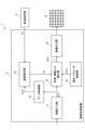
- FIG. 1 is a block diagram showing a configuration of an image display device 1 according to the first embodiment.
- the image display device 1 includes an image processing device 2 and a temperature measuring unit (for example, a temperature sensor that detects an environmental temperature which is an external temperature of the image display device 1) 3 for measuring air temperature. It has an image display unit 4 which is a display for displaying an image.
- the image processing device 2 can implement the image processing method according to the first embodiment.
- the image processing device 2 causes the image display unit 4 to display an image.
- the air temperature measuring unit 3 may be an external device configured to be able to communicate with the image display device 1. In this case, since the image display device 1 receives the air temperature measurement value Ta provided from the outside, it is not necessary to have the air temperature measurement unit 3.
- the image processing device 2 includes an image input unit 11, a data reduction unit 12, a temperature estimation unit 13, a correction parameter storage unit 14, a chromaticity / luminance unevenness correction unit 15, and an image. It has an output unit 16.
- the correction parameter storage unit 14 may be a storage device as an external configuration of the image processing device 2.
- the image input unit 11 and the image output unit 16 may have an external configuration of the image processing device 2.
- chromaticity / luminance means chromaticity and luminance, or luminance, or chromaticity. That is, “chromaticity / luminance” means at least one of chromaticity and luminance.
- chromaticity / luminance unevenness means chromaticity unevenness and luminance unevenness, luminance unevenness, or luminance unevenness. That is, “chromaticity / luminance unevenness” means at least one of chromaticity unevenness and luminance unevenness.
- FIG. 2A is a front view schematically showing a plurality of light emitting element units 40 provided in the image display unit 4 shown in FIG. 1, and FIG. 2B is a front view schematically showing one light emitting element unit 40. It is an enlarged view which shows the structure roughly.
- xmax pieces are used in the horizontal scanning direction (horizontal direction in FIG. 2A), and y in the vertical scanning direction (vertical direction in FIG. 2A).
- the max number of light emitting element units 40 are regularly arranged (for example, in a matrix).
- x max and y max are predetermined positive integers.
- Each light emitting element unit 40 has, for example, an LED chip as a light emitting element that emits red (R), green (G), and blue (B) light.
- the LED chips that emit R, G, and B light are also referred to as “LED chip for R”, “LED chip for G”, and “LED chip for B”, respectively. Further, the LED that emits R, G, and B light is also referred to as "LED chip for R, G, and B".
- each light emitting element unit (that is, each pixel) 40 has an LED chip for R, an LED chip for G, and B in one package. It has a structure provided with an LED chip for the purpose.
- the structure of the light emitting element unit 40 is not limited to the above, and may be any one having one or more light emitting elements. When one light emitting element unit 40 has one light emitting element, the light emitting element unit 40 and the light emitting element are the same.
- FIG. 3 (a) and 3 (b) are diagrams showing an example of changes in brightness and chromaticity of light generated in the light emitting element unit 40 having LEDs for R, G, and B depending on the temperature.
- FIG. 3A is a graph showing the luminance ratio (that is, the normalized value of luminance) Vp, which is the ratio of the luminance at the temperature T to the luminance, which is the luminance at the reference temperature Tr.
- FIG. 3B is a graph showing the chromaticity ratio (that is, the normalized value of the chromaticity) which is the ratio of the chromaticity at the temperature T to the reference chromaticity which is the chromaticity at the reference temperature Tr. As shown in FIGS.
- both or one of the brightness and chromaticity of the generated light depends on the temperature T. Change.
- the luminance ratio Vp decreases as the temperature T increases.
- the chromaticity is represented by, for example, the X stimulation value Xp and the Y stimulation value Yp of the CIE-XYZ color system.
- FIG. 3B shows changes in the X stimulus value Xp, which is the chromaticity ratio, and the Y stimulus value Yp, which is the chromaticity ratio.
- the X stimulation value Xp and the Y stimulation value Yp decrease as the temperature T increases.
- the image processing device 2 causes the image display unit 4 to display an image corresponding to the input image data.
- the image processing device 2 estimates and estimates the temperature of each light emitting element unit 40 (that is, the pixels of the coordinates (x, y)) of the image display unit 4 or the temperature of each of the LEDs based on the input image data.
- the temperature estimated value D13 also referred to as “Te” or “Te (x, y)”
- the image data for compensating for the change in chromaticity is corrected (for example, the image data for each pixel is corrected), and the corrected image data is supplied to the image display unit 4.
- the image processing device 2 may be partially or wholly composed of a processing circuit.
- the functions of the plurality of parts of the image processing device 2 may be realized by separate processing circuits, or the functions of the plurality of parts of the image processing device 2 may be collectively realized by one processing circuit. ..
- the processing circuit may be configured by hardware or may be configured by a computer that executes a program as software.
- a part of the functions of the image processing device 2 may be realized by hardware, and the other part may be realized by a computer that executes a program as software.
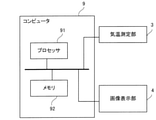
- FIG. 4 is a block diagram showing a computer 9 that realizes the functions of the image processing device 2 together with an image display unit 4 and an air temperature measurement unit 3.
- the computer 9 has a processor 91 as an information processing unit and a memory 92 as a storage unit.
- the processor 91 includes, for example, a CPU (Central Processing Unit), a GPU (Graphics Processing Unit), a microprocessor, a microcontroller, a DSP (Digital Signal Processor), and the like.
- a CPU Central Processing Unit
- GPU Graphics Processing Unit
- microprocessor a microcontroller
- DSP Digital Signal Processor
- the memory 92 is, for example, a RAM (Random Access Memory), a ROM (Read Only Memory), a flash memory, an EPROM (Erasable Programmable Read Only Memory), or an EPROM (Electrically Memory Memory) with an EPROM (Electrically Memory) .
- the memory 92 may include a magnetic disk, an optical disk, a magneto-optical disk, or the like.
- the processor 91 realizes the function of the image processing device 2 by executing the image processing program stored in the memory 92.
- the function of the image processing device 2 includes the control of the display operation in the image display unit 4.
- the computer 9 shown in FIG. 4 includes a single processor 91, but may include two or more processors.
- the image input unit 11 shown in FIG. 1 is a digital interface that receives digital image data and outputs n-bit (n is a positive integer) digital image data.
- the image input unit 11 receives digital image data and outputs the image data D11 to the data reduction unit 12 and the chromaticity / luminance unevenness correction unit 15.
- D11 is also written as "D11 (x, y)".
- D11 (x, y) means the image data of the pixel of the coordinate (x, y).
- the image input unit 11 may be an A / D (analog / digital) converter that converts an analog image signal into digital image data.
- FIG. 5 is a diagram showing an operation example of the data reduction unit 12.
- the data reduction unit 12 reduces the gradation of the image data D11 for each pixel to generate the image data D12 with the gradation reduced.
- D12 is also written as "D12 (x, y)".
- D12 (x, y) means image data in which the gradation of the pixel of the coordinate (x, y) is reduced.
- the data reduction unit 12 performs an operation represented by the equation (1), for example.
- X is the input data (8 bits) of a certain pixel in the image data D11 input to the data reduction unit 12
- Y is the gradation-reduced image data D12 output from the data reduction unit 12. Is the output data (6 bits) of the corresponding pixel in.
- the formula (1) is an image data D12 (that is, output data) output from the data reduction unit 12 with respect to a first value indicating the gradation of the image data D11 (that is, input data) input to the data reduction unit 12.
- the data retention rate which is the ratio of the second value indicating the gradation of), is higher as the gradation of the image data D11 input to the data reduction unit 12 is lower.
- the characteristics of the data reduction unit 12 are not limited to those shown in the equation (1) and FIG. However, it is desirable that the lower the gradation of the input image data D11, the higher the maintenance rate of the output image data D12. If it is not necessary to reduce the amount of data processed by the temperature estimation unit 13, the data reduction unit 12 can be omitted.
- the temperature estimation unit 13 shown in FIG. 1 is based on the temperature measurement value Ta output from the temperature measurement unit 3 and the image data D12 whose gradation is reduced for each pixel, and the temperature of each of the plurality of light emitting element units 40. Alternatively, the temperature of each of the LEDs is estimated, and the temperature estimation value Te indicating the estimated temperature is output. Te is also written as "Te (x, y)". Te (x, y) means the temperature estimate of the pixel at the coordinates (x, y).
- the chromaticity / luminance unevenness correction unit 15 shown in FIG. 1 is based on the temperature estimation value Te so that at least one unevenness of brightness and chromaticity due to temperature is compensated for each of the plurality of light emitting element units 40.
- the image data D11 is corrected.
- the temperature estimation unit 13 uses a trained neural network model formula for associating the gradation-reduced image data D12, the temperature measurement value Ta, and the respective temperatures of the light emitting element unit 40 with each other of the light emitting element unit 40.
- the temperature estimation value Te indicating the temperature is calculated.
- the parameter of the model formula stored in the correction parameter storage unit 14 is a value obtained by learning from the result of measuring the input / output relationship of the model formula in advance.
- the temperature estimation unit 13 estimates the individual temperature of each light emitting element unit 40 of the image display unit 4 or the temperature of each LED based on the gradation-reduced image data D12 and the temperature measurement value Ta.
- the estimated value Te is output to the chromaticity / luminance unevenness correction unit 15.
- the temperature estimation unit 13 is composed of, for example, a multi-layer neural network.
- FIG. 6 is a diagram showing an example of a neural network 13N constituting the temperature estimation unit 13.
- the neural network 13N shown in FIG. 6 has an input layer 131, an intermediate layer (that is, a hidden layer) 132, and an output layer 133.
- the number of intermediate layers is 3, but the number of intermediate layers may be 2 or less or 4 or more.
- Each of the neurons P of the input layer 131 is assigned the lighting rate of the LED to be measured, the temperature measurement value Ta, and the reduced image data D12.
- Each of the neurons P of the input layer 131 has any of the lighting rate of the LED to be measured, the temperature measurement value Ta, the reduced image data D12, and the past temperature estimation value (for example, the temperature estimation value one frame before). May be assigned.
- One of the temperature estimated value Te and the image data (that is, the pixel value) of each of the plurality of light emitting element units 40 is assigned to each of the plurality of light emitting element units 40, and each neuron P is assigned. Values (lighting rate, temperature measurement, temperature estimation, and image data) are input.
- the neuron P of the input layer 131 outputs the input as it is.
- the neuron P of the output layer 133 is composed of a plurality of bits, for example, 10 bits, and outputs data indicating the temperature estimation value Te of the selected light emitting element unit.
- Each of the neurons P in the intermediate layer 132 and the output layer 133 performs an operation represented by the following model formula (2) for a plurality of inputs.
- N is the number of inputs to neuron P.
- the number of inputs to neuron P is not always the same among neurons.
- x 1 to x N indicate the input data of the neuron P
- w 1 to w N indicate the weight for the input data x 1 to x N
- b indicates the bias.
- the weights w 1 to w N and the bias b are determined by learning. Further, the weights w1 to wN and the bias b are collectively referred to as parameters.
- the function s (a) is an activation function.
- the activation function may be, for example, a step function that outputs 0 if a is 0 or less, and outputs 1 otherwise.
- the activation function s (a) may be a ReLU (Rectifier Liner Unit) function that outputs 0 if a is 0 or less, and outputs an input value a otherwise, and the input value a is used as it is. It may be an equal function as an output value, or it may be a jigmoid function.
- the activation function used by the neuron P of the input layer 131 is an identity function.
- the step function or the jigmoid function may be used in the intermediate layer 132, and the ReLU function may be used in the output layer.
- different activation functions may be used between neurons P in the same layer.
- the number of neurons P and the number of layers are not limited to the example shown in FIG.
- the method of calculating the weight parameter of the temperature estimation unit 13 will be described.
- a plurality of patterns of input / output data of the temperature estimation unit 13 are measured in advance, and the difference between the output value (estimated value) in each input pattern and the measured value of the actual temperature is calculated.
- the weight parameters are learned so that the difference between the measured value and the estimated value in all patterns is minimized.
- the calculation method is not limited to this. Any value may be used as long as it is a value calculated in advance from the input / output data of the temperature estimation unit 13.
- the correction parameter storage unit 14 stores correction parameters for correcting changes in luminance and chromaticity due to temperature.
- the chromaticity / luminance unevenness correction unit 15 refers to the correction parameters stored in the correction parameter storage unit 14 according to the temperature estimated by the temperature estimation unit 13, and the image data supplied from the image input unit 11. To correct. This correction is performed for each R, G, B pixel. This correction is a correction for canceling changes in luminance and chromaticity due to changes in the temperature of the light emitting element unit 40.
- 7 (a) and 7 (b) show an example of the relationship between the input and the output defined by the correction parameter stored in the correction parameter storage unit 14.
- the relationship between the input and the output here is expressed by the ratio of the output to the input, that is, a coefficient. This coefficient is called a correction coefficient.
- the compensation table for luminance is the one having the input-output relationship exemplified in FIG. 7 (a), that is, the temperature. It is memorized that the change with respect to the rise is opposite to that in FIG. 7 (a).
- the compensation table is configured by the compensation coefficient Vq equal to the reciprocal of the normalized value of the luminance ratio Vp.
- the normalized value referred to here is a ratio to the brightness at the reference temperature.
- the correction parameter is the input-output relationship exemplified in FIG. 7 (b). That is, the one having the above, that is, the one in which the change with respect to the increase in temperature is opposite to that in FIG. 3 (b) is stored.
- the correction parameter of the X stimulus value is configured by the compensation coefficient Xq equal to the reciprocal of the normalized value of the X stimulus value Xp.
- the correction parameter of the Y stimulation value is configured by the compensation coefficient Yq equal to the reciprocal of the normalized value of the Y stimulation value Yp.
- the normalized value referred to here is a ratio to the X stimulation value and the Y stimulation value at the reference temperature.
- the correction parameter storage unit 14 may hold the chromaticity correction parameter as a correction parameter based on the chromaticity ratio, or may hold the correction parameter for converting each of R, G, and B.
- a value representing an average change is used as a curve showing the luminance and chromaticity of FIGS. 3 (a) and 3 (b).
- a correction parameter representing the compensation coefficients in FIGS. 7 (a) and 7 (b) is created to compensate for such an average change. Will be done.
- the correction parameter is set to the average value, but the present embodiment is not limited to this. Parameters may be set for each light emitting element.
- the correction parameter has a compensation coefficient value for each of the possible values of the temperature of the light emitting element, but is not limited to this. That is, for the temperature of the light emitting element which has the value of the compensation coefficient discretely with respect to the temperature of the light emitting element and does not have the value of the compensation coefficient, the value of the corresponding compensation coefficient may be obtained by interpolation. This interpolation can be performed, for example, by using the value of the compensation coefficient corresponding to the temperature value (table point) having the value of the compensation coefficient.
- the correction parameters may be different for each of the light emitting elements of R, G, and B.
- the image output unit 16 converts the image data D15 output from the chromaticity / luminance unevenness correction unit 15 into a signal in a format that matches the display method of the image display unit 4, and outputs the converted image signal D16. For example, when the light emitting element unit of the image display unit 4 emits light by PWM (Pulse Width Modulation) drive, the image output unit 16 converts the gradation value of the image data into a PWM signal.
- PWM Pulse Width Modulation
- the image display unit 4 displays an image based on the image signal received from the image processing device 2.
- changes in brightness and chromaticity due to temperature are compensated for each light emitting element unit (that is, a pixel) or for each LED (that is, a sub-pixel). Therefore, the uneven brightness and uneven chromaticity of the image displayed on the image display unit 4 are reduced.
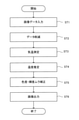
- FIG. 8 is a flowchart showing an image processing method implemented by the image processing device 2.
- the processing shown in FIG. 8 indicates the processing by the processor 91.
- step ST1 when the image data is input to the image input unit 11, the process by the image input unit 11 is executed.
- steps ST2 and ST3 the data reduction unit 12 reduces the data and measures the temperature.
- the temperature estimation unit 13 estimates the temperature of each light emitting element unit 40.
- step ST5 the estimated temperature value is stored in the estimated temperature storage unit 17.
- step ST6 the chromaticity / luminance unevenness correction unit 15 corrects the brightness and the chromaticity, and the image data is output from the image output unit 16.
- FIG. 9 is a block diagram showing the image display device according to the first embodiment together with the learning device 20, the trained model storage unit 23, and the learning temperature measuring unit 24.
- the learning device 20 has a data acquisition unit 22 and a model generation unit 21.
- the learning temperature measuring unit 24 has one or more temperature sensors. Each of the one or more temperature sensors is provided corresponding to one or more light emitting element units of the plurality of light emitting element units 40 constituting the image display unit 4, and each temperature sensor is provided with the corresponding light emitting element unit. The temperature of 40 is measured, and the temperature measurement values Tf (1), Tf (2), ... Are acquired.
- One or more light emitting element units to be measured for temperature are specified in advance.
- a light emitting element unit located in the center of the screen may be specified, or a light emitting element unit located between the center of the screen and the peripheral portion may be specified.
- the learning device 20 may be configured by a computer.
- the learning device 101 may be configured by the same computer.
- the computer constituting the learning device 101 may be, for example, the one shown in FIG. In that case, the function of the learning device 101 may be realized by the processor 91 executing the program stored in the memory 92.
- the learning device 20 operates a part of the image processing device 2, causes the temperature estimation unit 13 to estimate the temperature of the designated light emitting element unit, and the temperature estimation value Te (x d , y d ) is the temperature measurement for learning. Learning is performed so as to be close to the temperature measurement value Tf (x d , y d ) of the designated light emitting element unit obtained by the measurement of the unit 24.
- the model generation unit 21 stores the parameters of the equation (2), which is the result of learning, in the trained model storage unit 23.
- the parameters stored in the trained model storage unit 23 are provided in the correction parameter storage unit 14. Alternatively, the trained model storage unit 23 may be a part of the correction parameter storage unit 14.
- the temperature sensor of the learning temperature measuring unit 24 is removed, and the image display device 1 is used in a state where the temperature sensor is removed. That is, when used for image display, the image display device 1 does not require a temperature sensor for detecting the temperature of the light emitting element unit. This is because the temperature estimation unit 13 can estimate the temperature of the light emitting element unit or the temperature of each of the LEDs even if there is no temperature sensor for detecting the temperature of the light emitting element unit.
- the learning device 20 may be removed or may remain attached after learning is completed.
- the function of the learning device 101 is realized by executing a program by the processor 91, the program may remain stored in the memory 92.
- the temperature of each of the light emitting element units 40 or the temperature of each of the LEDs is estimated without the need for a temperature sensor for each LED, and the brightness unevenness and the chromaticity unevenness due to the temperature are estimated. One or both can be corrected.
- the calculation amount of the temperature estimation unit 13 can be reduced as compared with the case where the temperature estimation is performed with the input image without gradation reduction without using the data reduction unit.
- the data retention rate by the data reduction unit 12 is higher as the gradation of the image data D11 input to the data reduction unit 12 is lower. Therefore, the accuracy of the temperature estimation value Te at the time of low gradation can be improved.
- FIG. 10 is a block diagram showing the configuration of the image display device 1a according to the second embodiment.
- components that are the same as or correspond to the components shown in FIG. 1 are designated by the same reference numerals as those shown in FIG.
- the image display device 1a according to the second embodiment is different from the image display device 1 according to the first embodiment in the points shown in the following (E1) to (E3).
- the image processing device 2a has an estimated temperature storage unit 17 that stores the temperature estimated by the temperature estimation unit 13a as a past temperature estimation value Tp.
- the temperature estimation unit 13a of the image processing apparatus 2a has one or more past times (preferably, a plurality of times) stored in the temperature measurement value Ta, the image data D12 with reduced gradation, and the estimated temperature storage unit 17.
- the temperature of each of the plurality of light emitting element units 40 that is, the temperature of each pixel is estimated based on the temperature estimation value Tp of (time). This process is performed, for example, as shown in (E3) below.
- the temperature estimation unit 13a of the image processing apparatus 2a has the temperature estimation value Tp of one or more past times stored in the gradation-reduced image data D12, the temperature measurement value Ta, and the estimation temperature storage unit 17. Using the model formula of the trained neural network that associates the temperature estimated value Te of each of the light emitting element units 40 with the temperature estimated value Te of each of the light emitting element units 40, the temperature estimated value Te of each of the light emitting element units 40, that is, the temperature of each pixel is calculated.
- FIG. 11 is a diagram showing an example of the neural network 13Na constituting the temperature estimation unit 13a shown in FIG.
- the neural network 13Na is a model formula of a multi-layer neural network that inputs image data N12 with reduced gradation, temperature measurement value Ta, and temperature estimation value Tp at multiple times in the past, and outputs the temperature of each LED of the image display unit 4. It has become.
- the neural network 13Na shown in FIG. 11 has an input layer 131a, an intermediate layer 132a, and an output layer 133a. In the illustrated example, the number of intermediate layers 132a is 3, but the number of intermediate layers 132a may be 2 or less or 4 or more.
- Each of the neurons P of the input layer 131a is assigned one of the lighting rate of the LED to be measured, the temperature measurement value Ta, the gradation-reduced image data D12, and the past temperature estimation value Tp.
- One of the temperature estimated value Te and the image data (that is, the pixel value) of each of the plurality of light emitting element units 40 is assigned to each of the plurality of light emitting element units 40, and each neuron P is assigned.
- Values (lighting rate, temperature measurement, temperature estimation, and image data) are input.
- the neuron P of the input layer 131a outputs the input as it is.
- the neuron P of the output layer 133a is composed of a plurality of bits, for example, 10 bits, and outputs data indicating the temperature estimation value Te (x, y) of the selected light emitting element unit.
- Each of the neurons P in the intermediate layer 132a and the output layer 133a performs an operation represented by the following model formula (3) for a plurality of inputs.
- N is the number of inputs to neuron P.
- the number of inputs to neuron P is not necessarily the same among neurons.
- x 1 to x N indicate the input data of the neuron P
- w 1 to w N indicate the weight for the input data x 1 to x N
- b indicates the bias.
- the weights w 1 to w N and the bias b are determined by learning. Equation (3) is the same as the above equation (2) in terms of notation, but the actual values of the weights w1 to wN and the bias b are different.
- FIG. 12 is a flowchart showing an image processing method implemented by the image processing device 2a.
- the same or corresponding step as the step shown in FIG. 8 is designated by the same reference numeral as that shown in FIG.
- the temperature estimated by the temperature estimation unit 13a is stored in the estimated temperature storage unit 17 as the past temperature estimation value Tp in step ST7, and the temperature measurement value Ta and the gradation are stored in step ST4a.
- the image processing method according to the first embodiment is different from the image processing method according to the first embodiment in that the temperature of each of the plurality of light emitting element units 40 is estimated based on the reduced image data D12 and the past temperature estimation value Tp.
- the second embodiment it is not necessary to provide a temperature sensor for each of the light emitting element units 40 or each LED, and the temperature of each LED is estimated, and one of the luminance unevenness and the chromaticity unevenness due to the temperature, or one of them. Both can be corrected.
- the calculation amount of the temperature estimation unit 13 can be reduced as compared with the case where the temperature estimation is performed with the input image without gradation reduction without using the data reduction unit.
- the data retention rate by the data reduction unit 12 is higher as the gradation of the image data D11 input to the data reduction unit 12 is lower. Therefore, the accuracy of the temperature estimation value Te at the time of low gradation can be improved.
- the temperature estimation unit 13a can use the temperature estimation value Tp at one or more times in the past, so that the accuracy of the temperature estimation value Te can be improved.
Landscapes
- Engineering & Computer Science (AREA)
- Physics & Mathematics (AREA)
- Computer Hardware Design (AREA)
- General Physics & Mathematics (AREA)
- Theoretical Computer Science (AREA)
- Control Of El Displays (AREA)
- Control Of Indicators Other Than Cathode Ray Tubes (AREA)
Priority Applications (2)
| Application Number | Priority Date | Filing Date | Title |
|---|---|---|---|
| PCT/JP2020/034026 WO2022054148A1 (ja) | 2020-09-09 | 2020-09-09 | 画像処理装置、画像表示装置、画像処理方法、及び画像処理プログラム |
| JP2022548280A JP7275402B2 (ja) | 2020-09-09 | 2020-09-09 | 画像処理装置、画像表示装置、画像処理方法、及び画像処理プログラム |
Applications Claiming Priority (1)
| Application Number | Priority Date | Filing Date | Title |
|---|---|---|---|
| PCT/JP2020/034026 WO2022054148A1 (ja) | 2020-09-09 | 2020-09-09 | 画像処理装置、画像表示装置、画像処理方法、及び画像処理プログラム |
Publications (1)
| Publication Number | Publication Date |
|---|---|
| WO2022054148A1 true WO2022054148A1 (ja) | 2022-03-17 |
Family
ID=80630422
Family Applications (1)
| Application Number | Title | Priority Date | Filing Date |
|---|---|---|---|
| PCT/JP2020/034026 Ceased WO2022054148A1 (ja) | 2020-09-09 | 2020-09-09 | 画像処理装置、画像表示装置、画像処理方法、及び画像処理プログラム |
Country Status (2)
| Country | Link |
|---|---|
| JP (1) | JP7275402B2 (https=) |
| WO (1) | WO2022054148A1 (https=) |
Cited By (2)
| Publication number | Priority date | Publication date | Assignee | Title |
|---|---|---|---|---|
| WO2025031292A1 (zh) * | 2023-08-10 | 2025-02-13 | 深圳市奥拓电子股份有限公司 | 一种led显示屏逐点色度校正的温度补偿方法、装置和系统 |
| WO2025032742A1 (ja) * | 2023-08-08 | 2025-02-13 | シャープディスプレイテクノロジー株式会社 | パネル面内温度予測方法、機械学習モデル及び機械学習モデルの構築方法 |
Citations (4)
| Publication number | Priority date | Publication date | Assignee | Title |
|---|---|---|---|---|
| JP2012237972A (ja) * | 2011-04-26 | 2012-12-06 | Canon Inc | 温度推定装置、その制御方法、及び画像表示装置 |
| JP2014013335A (ja) * | 2012-07-05 | 2014-01-23 | Canon Inc | 表示装置及び表示パネルの駆動方法 |
| US20170236490A1 (en) * | 2016-02-17 | 2017-08-17 | Samsung Display Co., Ltd. | Luminance compensator in display device |
| WO2019059000A1 (ja) * | 2017-09-25 | 2019-03-28 | Eizo株式会社 | 雰囲気温度推定装置、雰囲気温度推定方法、プログラム及びシステム |
-
2020
- 2020-09-09 JP JP2022548280A patent/JP7275402B2/ja active Active
- 2020-09-09 WO PCT/JP2020/034026 patent/WO2022054148A1/ja not_active Ceased
Patent Citations (4)
| Publication number | Priority date | Publication date | Assignee | Title |
|---|---|---|---|---|
| JP2012237972A (ja) * | 2011-04-26 | 2012-12-06 | Canon Inc | 温度推定装置、その制御方法、及び画像表示装置 |
| JP2014013335A (ja) * | 2012-07-05 | 2014-01-23 | Canon Inc | 表示装置及び表示パネルの駆動方法 |
| US20170236490A1 (en) * | 2016-02-17 | 2017-08-17 | Samsung Display Co., Ltd. | Luminance compensator in display device |
| WO2019059000A1 (ja) * | 2017-09-25 | 2019-03-28 | Eizo株式会社 | 雰囲気温度推定装置、雰囲気温度推定方法、プログラム及びシステム |
Cited By (2)
| Publication number | Priority date | Publication date | Assignee | Title |
|---|---|---|---|---|
| WO2025032742A1 (ja) * | 2023-08-08 | 2025-02-13 | シャープディスプレイテクノロジー株式会社 | パネル面内温度予測方法、機械学習モデル及び機械学習モデルの構築方法 |
| WO2025031292A1 (zh) * | 2023-08-10 | 2025-02-13 | 深圳市奥拓电子股份有限公司 | 一种led显示屏逐点色度校正的温度补偿方法、装置和系统 |
Also Published As
| Publication number | Publication date |
|---|---|
| JPWO2022054148A1 (https=) | 2022-03-17 |
| JP7275402B2 (ja) | 2023-05-17 |
Similar Documents
| Publication | Publication Date | Title |
|---|---|---|
| US9858853B2 (en) | OLED display system and method | |
| US20220208065A1 (en) | Image processing device, method, image display device, and recording medium | |
| CN102239514B (zh) | 显示装置及其驱动方法 | |
| JP2012237972A (ja) | 温度推定装置、その制御方法、及び画像表示装置 | |
| JP2003333614A (ja) | 画像処理システム、プロジェクタ、画像処理方法、プログラムおよび情報記憶媒体 | |
| JP6976599B2 (ja) | 画像表示装置 | |
| JP2012230348A (ja) | 映像表示装置および映像表示装置の色補正方法 | |
| KR102940633B1 (ko) | 상이한 픽셀 레이아웃들의 영역들을 포함하는 디스플레이 패널에 대한 ir 드롭 보상 | |
| JP2015031874A (ja) | 表示装置、表示装置の制御方法、及び、プログラム | |
| JP2009192963A (ja) | 画像表示装置および画像表示方法 | |
| JP7275402B2 (ja) | 画像処理装置、画像表示装置、画像処理方法、及び画像処理プログラム | |
| CN115019723B (zh) | 屏幕显示方法、屏幕显示装置、电子设备、程序及介质 | |
| TW201320049A (zh) | 四原色顯示器及第四原色相對亮度計算方法 | |
| CN109658864B (zh) | 一种显示面板显示处理方法和显示处理装置 | |
| CN113393805B (zh) | Led显示屏的rgb三色伽玛校正方法、系统及其计算机存储介质 | |
| JP6478688B2 (ja) | 画像処理装置及び画像処理方法 | |
| CN111402796B (zh) | 图像处理方法以及图像处理系统 | |
| CN110021268B (zh) | Oled的显示控制方法和装置 | |
| JP7313287B2 (ja) | デュアル表示パネルに画像を表示するための方法及びその装置 | |
| CN110896466B (zh) | 一种显示装置的白平衡调整方法及系统 | |
| JP7471416B2 (ja) | 画像処理装置、表示制御装置、画像表示装置、画像処理方法、プログラム、及び記録媒体 | |
| JPWO2022054148A5 (https=) | ||
| US20220309999A1 (en) | Image display device, display control device, image processing device, and recording medium | |
| KR102323358B1 (ko) | 유기발광표시장치 및 그 표시방법 | |
| TWI672534B (zh) | 適用於顯示器背光的區域調光系統與方法 |
Legal Events
| Date | Code | Title | Description |
|---|---|---|---|
| 121 | Ep: the epo has been informed by wipo that ep was designated in this application |
Ref document number: 20953216 Country of ref document: EP Kind code of ref document: A1 |
|
| ENP | Entry into the national phase |
Ref document number: 2022548280 Country of ref document: JP Kind code of ref document: A |
|
| NENP | Non-entry into the national phase |
Ref country code: DE |
|
| 122 | Ep: pct application non-entry in european phase |
Ref document number: 20953216 Country of ref document: EP Kind code of ref document: A1 |