WO2022050307A1 - 警告灯、車両用警告灯 - Google Patents
警告灯、車両用警告灯 Download PDFInfo
- Publication number
- WO2022050307A1 WO2022050307A1 PCT/JP2021/032114 JP2021032114W WO2022050307A1 WO 2022050307 A1 WO2022050307 A1 WO 2022050307A1 JP 2021032114 W JP2021032114 W JP 2021032114W WO 2022050307 A1 WO2022050307 A1 WO 2022050307A1
- Authority
- WO
- WIPO (PCT)
- Prior art keywords
- warning
- light source
- light
- warning light
- warning lamp
- Prior art date
- Legal status (The legal status is an assumption and is not a legal conclusion. Google has not performed a legal analysis and makes no representation as to the accuracy of the status listed.)
- Ceased
Links
Images




Classifications
-
- B—PERFORMING OPERATIONS; TRANSPORTING
- B60—VEHICLES IN GENERAL
- B60Q—ARRANGEMENT OF SIGNALLING OR LIGHTING DEVICES, THE MOUNTING OR SUPPORTING THEREOF OR CIRCUITS THEREFOR, FOR VEHICLES IN GENERAL
- B60Q1/00—Arrangement of optical signalling or lighting devices, the mounting or supporting thereof or circuits therefor
- B60Q1/26—Arrangement of optical signalling or lighting devices, the mounting or supporting thereof or circuits therefor the devices being primarily intended to indicate the vehicle, or parts thereof, or to give signals, to other traffic
- B60Q1/50—Arrangement of optical signalling or lighting devices, the mounting or supporting thereof or circuits therefor the devices being primarily intended to indicate the vehicle, or parts thereof, or to give signals, to other traffic for indicating other intentions or conditions, e.g. request for waiting or overtaking
- B60Q1/52—Arrangement of optical signalling or lighting devices, the mounting or supporting thereof or circuits therefor the devices being primarily intended to indicate the vehicle, or parts thereof, or to give signals, to other traffic for indicating other intentions or conditions, e.g. request for waiting or overtaking for indicating emergencies
-
- F—MECHANICAL ENGINEERING; LIGHTING; HEATING; WEAPONS; BLASTING
- F21—LIGHTING
- F21S—NON-PORTABLE LIGHTING DEVICES; SYSTEMS THEREOF; VEHICLE LIGHTING DEVICES SPECIALLY ADAPTED FOR VEHICLE EXTERIORS
- F21S10/00—Lighting devices or systems producing a varying lighting effect
- F21S10/06—Lighting devices or systems producing a varying lighting effect flashing, e.g. with rotating reflector or light source
-
- F—MECHANICAL ENGINEERING; LIGHTING; HEATING; WEAPONS; BLASTING
- F21—LIGHTING
- F21W—INDEXING SCHEME ASSOCIATED WITH SUBCLASSES F21K, F21L, F21S and F21V, RELATING TO USES OR APPLICATIONS OF LIGHTING DEVICES OR SYSTEMS
- F21W2103/00—Exterior vehicle lighting devices for signalling purposes
-
- F—MECHANICAL ENGINEERING; LIGHTING; HEATING; WEAPONS; BLASTING
- F21—LIGHTING
- F21Y—INDEXING SCHEME ASSOCIATED WITH SUBCLASSES F21K, F21L, F21S and F21V, RELATING TO THE FORM OR THE KIND OF THE LIGHT SOURCES OR OF THE COLOUR OF THE LIGHT EMITTED
- F21Y2115/00—Light-generating elements of semiconductor light sources
- F21Y2115/10—Light-emitting diodes [LED]
Definitions
- the present invention relates to a warning light for avoiding a collision between a moving body and a person passing by, and a warning light for a vehicle mounted on a vehicle.
- Patent Document 1 a warning that the tilt characteristic of the LED light source rising from dark to light and the tilting characteristic of falling from light to dark are controlled to have a gentle tilt characteristic to reduce the glare of blinking.
- the invention of the light has been proposed.
- an object of the present invention is to provide a warning light capable of illuminating a warning light having an appropriate brightness to an object for which a warning is to be issued, and a warning light for a vehicle.
- the warning light of the present invention can be configured as follows.
- a warning light including a light source that emits a warning light, a rotating reflector that distributes the warning light, and a rotating table on which the light source and the rotating reflector are placed, and the warning light is a predetermined value around the warning light.
- a sensor for detecting an object and a control means for controlling a light source based on the detection result of the sensor are provided, and the control means is a light source so as to perform different illumination in an area including the object and another area. To control.
- the control means controls the light source so as to spot-illuminate the area including the object.
- the control means controls the light source so that the area including the object is illuminated with a predetermined blinking pattern or a predetermined color.
- the control means controls the light source so as to block the spot including the area including the object.
- warning lights (1) mount the warning lights (1) to (4) on the vehicle and use them as warning lights for the vehicle.
- an object around the warning light is detected by a sensor, the warning light from the light source is reflected by a rotary reflector, and the area including the object and other areas. Since it was decided to implement different lighting, only the area including the person who wants to issue a warning can be illuminated with the warning light, and the other areas can be dimly illuminated or turned off to appropriately warn the target who wants to issue a warning. It works. In addition, since the light can be distributed over a wide range and with high definition by using the rotary reflector, the number of LEDs used as the light source can be significantly reduced.
- the warning lamp 1 shown in FIGS. 1 and 2 includes a lamp body 7 attached to the roof of the vehicle V and a translucent cover 8 made of a transparent resin material.
- the lamp body 7 is sealed by a translucent cover 8, and a lamp chamber 9 is formed inside both of them.
- a police car, a road inspection vehicle, an unmanned compact car for delivery, or the like can be selected.
- a light source (LED2) that emits a warning light L, a rotating reflector 3 that distributes the light L, a lens 11 that projects the reflected light from the rotating reflector 3 to the outside of the lamp, a light source, and rotation.
- a turntable 6 on which a reflector 3 and a lens 11 are mounted, a sensor 4 that detects a predetermined object such as a person P around the warning light 1, and a control unit 5 that controls a light source based on the detection result of the sensor 4 are provided. It is contained.
- the rotary reflector 3 is held on the rotary table 6 by the housing 12.
- a motor 62 that rotates the shaft 61 at a predetermined rotation speed is connected to the rotary table 6.
- the sensor 4 is configured to detect the person P as a warning target. Further, the detection result of the sensor 4 includes the position of the person P, the distance between the person P and the vehicle V, and the like.
- a sensor capable of measuring a distance such as a LiDAR, a millimeter wave radar, an ultrasonic sensor, a stereo camera, and an acceleration / gyro sensor can be selected.
- the control unit 5 is composed of a control circuit and a board on which the control circuit is mounted.
- the control unit 5 determines whether or not the detected person P is a warning target based on the detection result of the sensor 4, and if it is a warning target, selects a warning method.
- Whether or not it is a warning target can be determined, for example, by making it a warning target when approaching the vehicle V and not a warning target when moving away from the vehicle V. Further, as a warning method, it is possible to control passing once when approaching within 5 m of the collision course and twice as passing when approaching within 3 m of the collision course. Furthermore, when passing, it is also possible to pass with the color having the highest luminosity factor in the time zone. As a color having high luminosity factor, green light (wavelength of about 555 nm) can be selected in the daytime and blue-green light (wavelength of about 507 nm) can be selected in the nighttime.
- the light source is composed of a plurality of LEDs 2 arranged on the substrate 10.
- the parallel LEDs 2a to 2d each illuminate the area 21 arranged in the vertical direction. Further, the rows of LEDs 2 and 2'have the effect of increasing the brightness and adjusting the color by superimposing and illuminating the area 21.
- the LED 2 is composed of "RGB LEDs"
- the color to be illuminated can be appropriately adjusted to a color having high luminosity factor or the like.
- the rotary reflector 3 includes a plurality of blades 33 rotatably provided around the shaft 31 and a motor 32 (see FIG. 2) for driving the shaft 31.
- Each blade 33 includes a reflecting surface 34 that reflects the light of the LED 2, and the reflecting surface 34 is provided so as to be inclined while drawing a concave curved surface from one end 33a side to the other end 33b side of the blade 33. .. Therefore, when the LED 2 is turned on and the blade 33 is rotated, the light reflected by the reflecting surface 34 is emitted so as to scan the periphery of the warning light 1 in the horizontal direction.
- the time during which the horizontal scanning is performed once will be described as the period T.
- the rotary reflector 3 can widely distribute the light of one LED 2 in the horizontal direction, it is not necessary to arrange a large number of LEDs horizontally (parallel), for example, 12 (parallel 6 ⁇ 2). It is possible to use the LED 2 to illuminate an area having the same area as 300 (parallel 6 ⁇ 50 horizontal rows) LEDs 2.
- the constant width w can be darkened.
- spot shading a state in which the LED 2 is not illuminated due to being turned off and is darkened.
- the LED 2 is turned on during the time t, a certain width w can be spot-lit. ..
- the position of turning off the spot point can be adjusted by adjusting the timing of the time t in the cycle T. Further, by adjusting the length of the time t, the width w of the spot point extinguishing can be adjusted.
- the operation of the control unit 5 based on the detection result of the sensor 4 and the lighting pattern of the warning light 1 will be described with reference to FIGS. 4 to 8.
- the thick arrow indicates the traveling direction of the vehicle V and the person P.
- the control unit 5 inputs the detection result from the sensor 4, and is the person P detected by the sensor 4 based on the detection result a warning target? Judge whether or not.
- the person P 3 is far from the vehicle V, it is determined that the person P 3 is not a warning target.
- other people P1, P2, and P4 are judged as warning targets.
- spot illumination is performed toward the warning target persons P1, P2, and P4 .
- the control unit 5 spot-illuminates only the area 21 including the humans P1, P2, and P4, and sets a light source so that the area 22 other than the area 21 is not always illuminated. Control. Specifically, the control unit 5 lights the LEDs 2b and 2c during the time t in the period T. At this time, the region 21 is preferably a portion above the shoulders of the people P1 , P2, and P4 .
- the frequency of the period T n-1 and the period T n it is possible to adjust the number of passing times.
- control unit 5 performs spot shading on the person P3 determined not to be a warning target.
- the control unit 5 spot - shields only the region 21 including the person P3, and the region 22 other than the region 21 is illuminated at a cycle corresponding to the rotation speed of the rotary table 6.
- control the light source Specifically, the control unit 5 turns off the LEDs 2b and 2c during the time t in the period T.
- the region 21 is preferably a portion above the shoulder of the person P3 .
- control unit 5 can control the light source so as to illuminate the area 21 and the area 22 in the patterns 1 to 12.
- the warning target is determined based on the detection result of the sensor 4, and the spot illumination is directed only to the warning target person P. Therefore, the warning is given even on a busy road or indoors. It is possible to appropriately warn the necessary opponent and notify the approach of the vehicle V. Further, when passing is added to the spot lighting, it is possible to warn more effectively and also to notify the approaching state with the vehicle V. On the other hand, when the spot is shielded from the shoulder to the face of the person P other than the warning target, unnecessary warnings are suppressed and the person P around the vehicle can pass comfortably.
- a warning can be given with a light of a suitable color according to the time zone, so that the person P around the vehicle V can surely recognize the warning by the warning light 1. ..
- the present invention is not limited to the above embodiment, and it is possible to appropriately change the shape and configuration of each part within a range that does not deviate from the gist of the present invention.
- Warning light 1 Warning light 2 LED 3 Rotating reflector 4 Sensor 5 Control unit 6 Rotary table 7 Lighting equipment body 8 Translucent cover 9 Lighting room 10 Board 11 Lens 12 Housing 21 Area containing the object 22 Area other than the area containing the object 31 Axis 32 Motor 33 Blade ( a: one end, b: the other end) 34 Reflective surface 61 axis V vehicle P person w width T cycle t time L light
Landscapes
- Engineering & Computer Science (AREA)
- General Engineering & Computer Science (AREA)
- Mechanical Engineering (AREA)
- Non-Portable Lighting Devices Or Systems Thereof (AREA)
- Lighting Device Outwards From Vehicle And Optical Signal (AREA)
Abstract
【課題】警告灯周辺を通行する人など、警告を発したい対象に、適切な明るさで警告光を照明できる警告灯、および、車両用警告灯を提供する。 【解決手段】本願発明の警告灯、および車両用警告灯(1)は、警告光Lを出射する光源(LED2)と、光(L)を配光する回転リフレクタ(3)と、光源および回転リフレクタ(3)を載置した回転台(6)を有する。また、警告灯(1)は、警告灯周辺の所定の対象物を検知するセンサ(4)と、センサ(4)の検知結果に基づいて光源を制御する制御部(5)を備える。制御部(5)は、対象物を含む領域(21)をその他の領域(21)と異なる照明を実施するように光源を制御する。
Description
本発明は、移動体と周囲を通行する人との衝突を回避するための警告灯と、車両に搭載される車両用警告灯に関する。
従来、車両のルーフに回転灯を設置し、回転灯を点灯・点滅させて、車両の周囲を通行する人に警告を与える警告灯の技術が知られている。例えば、特許文献1には、LED光源の暗から明への立ち上がりの傾き特性と、明から暗への立ち下がりの傾き特性を傾きの緩やかな特性に制御し、点滅の眩しさを軽減した警告灯の発明が提案されている。
ところが、従来の警告灯によれば、人通りの多い道や屋内では必要以上に眩しかったり、反対に眩しさを軽減しすぎると、回転灯の光に気づかないなどの問題がある。特に、今後、無人宅配車や電動車椅子、無人運搬車両などの人の背丈よりも小さい無人低速小型モビリティが普及すると、車道以外に、歩道、屋内、エレベーターなど歩行者が通行中であったり、死角の多い場所を走ることも想定されるので、より細やかに警告光が出射出来る警告灯を運用することが求められる。
そこで、本発明の目的は、警告を発したい対象に対して適切な明るさの警告光を照明できる警告灯、および、車両用警告灯を提供することにある。
上記課題を解決するために、本発明の警告灯を以下のように構成することができる。
(1)警告光を出射する光源と、警告光を配光する回転リフレクタと、光源および回転リフレクタを載置した回転台と、を含む警告灯であって、警告灯が、警告灯周辺の所定の対象物を検知するセンサと、センサの検知結果に基づいて光源を制御する制御手段と、を備え、制御手段は、対象物を含む領域とその他の領域とで異なる照明を実施するように光源を制御する。
(1)警告光を出射する光源と、警告光を配光する回転リフレクタと、光源および回転リフレクタを載置した回転台と、を含む警告灯であって、警告灯が、警告灯周辺の所定の対象物を検知するセンサと、センサの検知結果に基づいて光源を制御する制御手段と、を備え、制御手段は、対象物を含む領域とその他の領域とで異なる照明を実施するように光源を制御する。
(2)制御手段は、対象物を含む領域をスポット照明するように光源を制御する。
(3)制御手段は、対象物を含む領域が所定の点滅パターンや、所定の色で照明されるように光源を制御する。
(4)制御手段は、対象物を含む領域をスポット遮光するように光源を制御する。
(1)~(4)の警告灯を車両に搭載し、車両用警告灯とすることもできる。
本発明の警告灯、車両用警告灯によれば、警告灯周辺の対象物をセンサで検知し、光源からの警告光を回転リフレクタで反射させ、該対象物を含む領域とその他の領域とで異なる照明を実施することとしたため、警告を発したい人を含む領域のみを警告光で照明し、その他の領域は暗く照明、あるいは消灯して、警告を発したい対象に対して適切に警告できるという効果を奏する。また、回転リフレクタを用いて広範囲かつ高精細に配光できるので、光源に用いるLEDの個数を大幅に削減できるという効果も奏する。
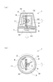
以下、本発明を車両用の警告灯に具体化した一実施形態を図面に基づいて説明する。図1,2に示す警告灯1は、車両Vのルーフに取り付けられる灯具ボディ7と、透明樹脂材料からなる透光カバー8を備えている。灯具ボディ7は、透光カバー8により密封され、両者の内側に灯室9が形成されている。警告灯1を搭載する車両Vとしては、パトカー、道路点検車両、配達などを行う無人小型車などを選択できる。
灯室9内には、警告光Lを出射する光源(LED2)と、光Lを配光する回転リフレクタ3と、回転リフレクタ3からの反射光を灯具外部に投影するレンズ11と、光源、回転リフレクタ3、レンズ11を載置した回転台6と、警告灯1周辺の人Pなどの所定の対象物を検知するセンサ4と、センサ4の検知結果に基づいて光源を制御する制御部5が収容されている。回転リフレクタ3は、筐体12によって回転台6に保持されている。回転台6には、軸61を所定の回転速度で回転させるモータ62が接続されている。
センサ4は、警告対象としての人Pを検知するように構成されている。また、センサ4の検知結果には、人Pの位置、人Pと車両Vとの距離などが含まれる。センサ4としては、LiDARやミリ波レーダ、超音波センサ、ステレオカメラ、加速度・ジャイロセンサなど、測距可能なセンサを選択できる。
制御部5は、制御回路と、制御回路を搭載した基板から構成されている。制御部5は、センサ4の検知結果に基づいて、検知された人Pが警告対象であるか否かを判断し、警告対象であった場合には、警告方法を選択する。
警告対象であるか否かの判断は、例えば、車両Vに接近する場合には警告対象とし、車両Vから離れてゆく場合には警告対象ではないとすることにより行うことができる。また、警告方法としては、衝突コース5m以内に接近した場合にはパッシングを1回、衝突コース3m以内に接近した場合にはパッシングを2回として制御することができる。さらに、パッシングの際には、時間帯で最も視感度の高い色でパッシングすることも可能である。視感度の高い色としては、昼間は緑色光(波長約555nm)、夜間は青緑色光(波長約507nm)を選択できる。
光源は、基板10に配設された複数個のLED2から構成される。縦列のLED2a~2dは、各々垂直方向に並ぶ領域21を照明する。また、横列のLED2,2’は、領域21を重畳して照明することにより、明るさを強めたり、色を調整したりする効果を生ずる。LED2を「RGB LED」で構成すると、照明する色を視感度の高い色などに、適宜調整することができる。
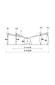
図3に示すように、回転リフレクタ3は、軸31の周りに回転可能に設けられた複数のブレード33と、軸31を駆動するモータ32(図2参照)を備えている。各々のブレード33は、LED2の光を反射する反射面34を備え、反射面34は、ブレード33の一端33a側から他端33b側に向けて凹曲面を描きつつ傾斜するように設けられている。このため、LED2を点灯し、ブレード33が回転すると、反射面34で反射した光が、警告灯1の周囲を水平方向に走査するように出射される。以下、水平方向の走査が1回行われる時間を周期Tとして説明する。
回転リフレクタ3は、1個のLED2の光を水平方向に幅広く配光することができるため、多数のLEDを水平(横列)に並べる必要が無くなり、例えば、12(縦列6×横列2)個のLED2を用いて300(縦列6×横列50)個のLED2と同じ面積の領域を照明することが可能となる。
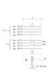
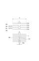
また、回転リフレクタ3を用いた場合、所定の時間tの間にLED2を消灯すると、一定の幅wを暗くすることができる。(ここでは、LED2の消灯により照明されず、暗くなった状態を「スポット遮光」と記載する。)反対に、時間tの間にLED2を点灯すると、一定の幅wをスポット照明することもできる。このとき、周期Tにおける時間tのタイミングを調整することにより、スポット点消灯の位置を調整できる。また、時間tの長さを調整することにより、スポット点消灯の幅wを調整できる。
次に、上記のように構成された車両用の警告灯1において、センサ4の検知結果に基づく制御部5の動作と、警告灯1の点灯パターンを図4~8に従って説明する。図中、太線矢印は、車両Vや人Pの進行方向を表している。
図4,7に示すように、センサ4が人Pを検知すると、制御部5は、センサ4から検知結果を入力し、検知結果に基づいてセンサ4により検知された人Pが、警告対象か否かを判定する。この例では、人P3は車両Vから遠ざかっているため、人P3を警告対象ではないと判定している。一方、その他の人P1,P2,P4を警告対象として判定している。図4では、警告対象の人P1,P2,P4に向けてスポット照明を行っている。
図5に示すように、制御部5は、人P1,P2,P4を含む領域21のみをスポット照明し、領域21以外の領域である領域22は、常に照明しないように、光源を制御する。具体的には、制御部5は、周期Tにおける時間tの間、LED2b,2cを点灯させる。このとき、領域21は、人P1,P2,P4の肩より上部分であることが好ましい。
図6に示すように、制御部5は、周期Tn-1と周期Tn(n=1,2,3,・・・n)を繰り返すことにより、領域21をパッシング(点滅)状態でスポット照明することもできる。周期Tn-1や周期Tnの頻度を調整することで、パッシング回数を調整することが可能である。
図7では、制御部5は、警告対象ではないと判定された人P3に対してスポット遮光を行っている。図8に示すように、制御部5は、人P3を含む領域21のみをスポット遮光し、領域21以外の領域である領域22は、回転台6の回転速度に応じた周期で照明するように、光源を制御する。具体的には、制御部5は、周期Tにおける時間tの間、LED2b,2cを消灯する。このとき、領域21は、人P3の肩より上部分であることが好ましい。
図9に示すように、制御部5では、パターン1~12で領域21および領域22を照明するように光源を制御することが可能である。
以上の構成の警告灯1によれば、センサ4の検出結果に基づいて警告対象を判定し、警告対象の人Pのみに向けてスポット照明するため、人通りの多い道や屋内でも、警告の必要な相手に適切に警告し、車両Vの接近を知らせることができる。また、スポット照明にパッシングを加えた場合には、より効果的に警告できるとともに、車両Vとの接近状態も知らせることが可能となる。一方、警告対象以外の人Pの肩から顔にかけてスポット遮光した場合には、不要な警告を抑制し、車両周辺の人Pが快適に通行できる。
さらに、LED2を「RGB LED」で構成した場合には、時間帯に応じて適した色の光で警告できるため、車両V周辺の人Pが確実に警告灯1による警告を認識することができる。
なお、本発明は、上記実施形態に限定されるものではなく、本発明の趣旨を逸脱しない範囲で各部の形状や構成を適宜に変更して実施することも可能である。
1 警告灯
2 LED
3 回転リフレクタ
4 センサ
5 制御部
6 回転台
7 灯具ボディ
8 透光カバー
9 灯室
10 基板
11 レンズ
12 筐体
21 対象物を含む領域
22 対象物を含む領域以外の領域
31 軸
32 モータ
33 ブレード(a:一端、b:他端)
34 反射面
61 軸
V 車両
P 人
w 幅
T 周期
t 時間
L 光
2 LED
3 回転リフレクタ
4 センサ
5 制御部
6 回転台
7 灯具ボディ
8 透光カバー
9 灯室
10 基板
11 レンズ
12 筐体
21 対象物を含む領域
22 対象物を含む領域以外の領域
31 軸
32 モータ
33 ブレード(a:一端、b:他端)
34 反射面
61 軸
V 車両
P 人
w 幅
T 周期
t 時間
L 光
Claims (6)
- 警告光を出射する光源と、前記警告光を配光する回転リフレクタと、前記光源および回転リフレクタを載置した回転台と、を含む警告灯であって、
前記警告灯が、警告灯周辺の所定の対象物を検知するセンサと、前記センサの検知結果に基づいて前記光源を制御する制御手段と、を備え、
前記制御手段は、前記対象物を含む領域とその他の領域とで異なる照明を実施するように前記光源を制御することを特徴とする警告灯。 - 前記制御手段は、前記対象物を含む領域をスポット照明するように前記光源を制御する請求項1に記載の警告灯。
- 前記制御手段は、前記対象物を含む領域が所定の点滅パターンで照明されるように前記光源を制御する請求項1または2に記載の警告灯。
- 前記制御手段は、前記対象物を含む領域が所定の色で照明されるように前記光源を制御する請求項1~3のいずれか一項に記載の警告灯。
- 前記制御手段は、前記対象物を含む領域をスポット遮光するように前記光源を制御する請求項1に記載の警告灯。
- 車両に搭載された請求項1~5のいずれか一項に記載の車両用警告灯。
Priority Applications (1)
| Application Number | Priority Date | Filing Date | Title |
|---|---|---|---|
| JP2022546944A JPWO2022050307A1 (ja) | 2020-09-04 | 2021-09-01 |
Applications Claiming Priority (2)
| Application Number | Priority Date | Filing Date | Title |
|---|---|---|---|
| JP2020-148877 | 2020-09-04 | ||
| JP2020148877 | 2020-09-04 |
Publications (1)
| Publication Number | Publication Date |
|---|---|
| WO2022050307A1 true WO2022050307A1 (ja) | 2022-03-10 |
Family
ID=80490983
Family Applications (1)
| Application Number | Title | Priority Date | Filing Date |
|---|---|---|---|
| PCT/JP2021/032114 Ceased WO2022050307A1 (ja) | 2020-09-04 | 2021-09-01 | 警告灯、車両用警告灯 |
Country Status (2)
| Country | Link |
|---|---|
| JP (1) | JPWO2022050307A1 (ja) |
| WO (1) | WO2022050307A1 (ja) |
Citations (3)
| Publication number | Priority date | Publication date | Assignee | Title |
|---|---|---|---|---|
| JP2011157023A (ja) * | 2010-02-03 | 2011-08-18 | Sharp Corp | 照明装置および移動体 |
| JP2013199263A (ja) * | 2012-02-24 | 2013-10-03 | Koito Mfg Co Ltd | 前照灯装置および前照灯制御システム |
| JP2019048526A (ja) * | 2017-09-08 | 2019-03-28 | スタンレー電気株式会社 | 車両の前照灯の制御装置 |
-
2021
- 2021-09-01 WO PCT/JP2021/032114 patent/WO2022050307A1/ja not_active Ceased
- 2021-09-01 JP JP2022546944A patent/JPWO2022050307A1/ja active Pending
Patent Citations (3)
| Publication number | Priority date | Publication date | Assignee | Title |
|---|---|---|---|---|
| JP2011157023A (ja) * | 2010-02-03 | 2011-08-18 | Sharp Corp | 照明装置および移動体 |
| JP2013199263A (ja) * | 2012-02-24 | 2013-10-03 | Koito Mfg Co Ltd | 前照灯装置および前照灯制御システム |
| JP2019048526A (ja) * | 2017-09-08 | 2019-03-28 | スタンレー電気株式会社 | 車両の前照灯の制御装置 |
Also Published As
| Publication number | Publication date |
|---|---|
| JPWO2022050307A1 (ja) | 2022-03-10 |
Similar Documents
| Publication | Publication Date | Title |
|---|---|---|
| JP6770790B2 (ja) | 車両用描画装置 | |
| US11009696B2 (en) | Vehicle lamp | |
| US10748015B2 (en) | Optical unit, vehicle monitor, and obstruction detector | |
| CN100387461C (zh) | 防止眩光的前灯控制 | |
| JP5271002B2 (ja) | 車両用灯具 | |
| US10883692B2 (en) | Lamp unit and vehicular headlamp | |
| JPWO2019082980A1 (ja) | 車両用前照灯システム、車両用ランプシステム | |
| CN112770938A (zh) | 车辆用照明灯 | |
| CN119058533A (zh) | 车辆用灯具系统 | |
| JP2013508900A (ja) | 車両のヘッドライト照明の制御装置 | |
| EP2399777B1 (en) | Control device, vehicle headlamp, and vehicle headlamp system | |
| WO2020067497A1 (ja) | 車両用前照灯 | |
| JP2018058542A (ja) | 車両用照明装置 | |
| JP2020055516A (ja) | 車両用前照灯 | |
| CN104890564A (zh) | 车辆前照灯 | |
| JP2019199224A (ja) | 車両用前照灯装置 | |
| JP2009286199A (ja) | 歩行者照射用照明装置および車両用前照灯装置 | |
| JP7585172B2 (ja) | 車両用灯具 | |
| WO2022050307A1 (ja) | 警告灯、車両用警告灯 | |
| JP2020032803A (ja) | 車両のヘッドライト装置 | |
| CN211442116U (zh) | 车辆不可见光投射装置、目标物检测装置及智能驾驶汽车 | |
| JP2025184753A (ja) | 車両用ランプシステム | |
| JP6691036B2 (ja) | 車両用照明装置 | |
| JP7610493B2 (ja) | 車両用前照灯 | |
| JP7591149B2 (ja) | 工事現場を通行する際の車両照明の調整方法および車両 |
Legal Events
| Date | Code | Title | Description |
|---|---|---|---|
| 121 | Ep: the epo has been informed by wipo that ep was designated in this application |
Ref document number: 21864364 Country of ref document: EP Kind code of ref document: A1 |
|
| ENP | Entry into the national phase |
Ref document number: 2022546944 Country of ref document: JP Kind code of ref document: A |
|
| NENP | Non-entry into the national phase |
Ref country code: DE |
|
| 122 | Ep: pct application non-entry in european phase |
Ref document number: 21864364 Country of ref document: EP Kind code of ref document: A1 |