WO2022049688A1 - Dilatateur - Google Patents
Dilatateur Download PDFInfo
- Publication number
- WO2022049688A1 WO2022049688A1 PCT/JP2020/033397 JP2020033397W WO2022049688A1 WO 2022049688 A1 WO2022049688 A1 WO 2022049688A1 JP 2020033397 W JP2020033397 W JP 2020033397W WO 2022049688 A1 WO2022049688 A1 WO 2022049688A1
- Authority
- WO
- WIPO (PCT)
- Prior art keywords
- coil
- end side
- dilator
- winding
- winding direction
- Prior art date
Links
Images

Classifications
-
- A—HUMAN NECESSITIES
- A61—MEDICAL OR VETERINARY SCIENCE; HYGIENE
- A61M—DEVICES FOR INTRODUCING MEDIA INTO, OR ONTO, THE BODY; DEVICES FOR TRANSDUCING BODY MEDIA OR FOR TAKING MEDIA FROM THE BODY; DEVICES FOR PRODUCING OR ENDING SLEEP OR STUPOR
- A61M29/00—Dilators with or without means for introducing media, e.g. remedies
-
- A—HUMAN NECESSITIES
- A61—MEDICAL OR VETERINARY SCIENCE; HYGIENE
- A61B—DIAGNOSIS; SURGERY; IDENTIFICATION
- A61B17/00—Surgical instruments, devices or methods, e.g. tourniquets
- A61B17/34—Trocars; Puncturing needles
-
- A—HUMAN NECESSITIES
- A61—MEDICAL OR VETERINARY SCIENCE; HYGIENE
- A61M—DEVICES FOR INTRODUCING MEDIA INTO, OR ONTO, THE BODY; DEVICES FOR TRANSDUCING BODY MEDIA OR FOR TAKING MEDIA FROM THE BODY; DEVICES FOR PRODUCING OR ENDING SLEEP OR STUPOR
- A61M25/00—Catheters; Hollow probes
- A61M25/0043—Catheters; Hollow probes characterised by structural features
- A61M25/005—Catheters; Hollow probes characterised by structural features with embedded materials for reinforcement, e.g. wires, coils, braids
- A61M25/0052—Localized reinforcement, e.g. where only a specific part of the catheter is reinforced, for rapid exchange guidewire port
-
- A—HUMAN NECESSITIES
- A61—MEDICAL OR VETERINARY SCIENCE; HYGIENE
- A61M—DEVICES FOR INTRODUCING MEDIA INTO, OR ONTO, THE BODY; DEVICES FOR TRANSDUCING BODY MEDIA OR FOR TAKING MEDIA FROM THE BODY; DEVICES FOR PRODUCING OR ENDING SLEEP OR STUPOR
- A61M25/00—Catheters; Hollow probes
- A61M25/01—Introducing, guiding, advancing, emplacing or holding catheters
Definitions
- This disclosure relates to dilators.
- Patent Document 1 discloses a medical device composed of hollow stranded wires. This hollow stranded wire has a first layer and a second layer, and is configured so that the strands of the first layer and the strands of the second layer are twisted in opposite directions.
- a dilator that expands a hole formed in the wall of a patient's digestive tract or the like for treatment.
- the hole is expanded by inserting the tip of the dilator into the hole formed in the wall and pushing the tapered portion into the hole.
- the hollow stranded wire composed of two layers described in Patent Document 1 is applied to the dilator, the inner layer is tightened and the outer layer is opened depending on the direction in which the dilator is rotated, and the two layers are in contact with each other. It may not be possible to obtain sufficient torque transmission.
- the present disclosure aims to provide a dilator capable of obtaining high torque transmissibility regardless of the rotation direction.
- the dilator according to one aspect of the present disclosure is located on the distal end side coil portion and the proximal end side of the distal end side coil portion, and the distal end portion is located on the proximal end portion of the distal end side coil portion.
- a base end side coil portion to be connected is provided, and the tip end side coil portion is provided on a first coil in which a wire is wound in a hollow shape in the first winding direction and an outer periphery of the first coil. It has a second coil in which a wire is wound in a second winding direction which is the opposite winding direction to the first winding direction, and the base end side coil portion has the second coil in which the wire is hollow. It has a third coil wound in the winding direction and a fourth coil provided on the outer periphery of the third coil and wound with a wire in the first winding direction.
- the first winding direction may be S winding
- the second winding direction may be Z winding
- the diameter of the wire of the third coil may be smaller than the diameter of the wire of the fourth coil.
- the base end portion of the tip end side coil portion and the tip end portion of the base end side coil portion may be welded to each other on the entire circumference thereof.
- the first coil and the third coil may be composed of separate strands, and the second coil and the fourth coil may be configured by separate strands.
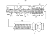
- FIG. 1 is an overall configuration diagram of a dilator according to an embodiment.
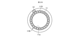
- FIG. 2A is a cross-sectional view taken along the line IIA-IIA of the dilator of FIG.
- FIG. 2B is a cross-sectional view taken along the line IIB-IIB of the dilator of FIG.
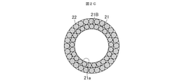
- FIG. 2C is a cross-sectional view taken along the line IIC-IIC of the dilator of FIG.
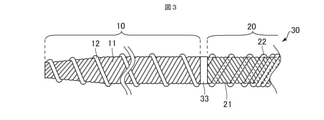
- FIG. 3 is a diagram showing a tip end side portion of the dilator according to the modified example.
- the "tip side” is a direction along the longitudinal direction of the dilator (a direction along the axial direction of the dilator), and is a direction in which the tip side coil portion is located with respect to the base end side coil portion.
- the “base end side” means a direction along the longitudinal direction of the dilator and a direction opposite to the tip end side.
- the "tip” indicates an end portion on the distal end side in any member or portion
- the “base end” indicates an end portion on the proximal end side in any member or portion.
- FIG. 1 is an overall configuration diagram of the dilator 1 according to the embodiment of the present disclosure.
- the left side in the drawing is the distal end side (distal side) inserted into the body, and the right side is the proximal end side (hand side, proximal side) operated by a technician such as a doctor.
- 2A is a cross-sectional view taken along the line IIA-IIA of the dilator 1 of FIG.
- FIG. 2B is a cross-sectional view taken along the line IIB-IIB of the dilator 1 of FIG. 1 is a cross-sectional view taken along the line IIC-IIC.
- the dilator 1 includes a tip side coil portion 10, a base end side coil portion 20, and a connector 2.
- the tip side coil portion 10 is located on the most tip side in the axial direction of the dilator 1 and has a first coil 11 and a second coil 12.
- the second coil 12 is wound around the outer peripheral surface of the first coil 11.
- the strands constituting the first coil 11 and the second coil 12 are, for example, metal strands such as stainless steel and superelastic alloys such as nickel-titanium, or resin strands.
- the first coil 11 is formed in a hollow shape by winding a plurality of (for example, 12) strands.
- the plurality of strands constituting the first coil 11 are wound in the first winding direction.
- the first coil 11 has a lumen 11a penetrating from the proximal end to the distal end.
- the first coil 11 has a straight portion 11B and a tapered portion 11C.
- the straight portion 11B is located on the proximal end side of the first coil 11, and the proximal end side coil portion 20 is connected to the proximal end.
- the straight portion 11B has a substantially constant outer diameter from its base end to the tip end.
- the tapered portion 11C is located on the tip end side of the straight portion 11B, extends from the tip end of the straight portion 11B toward the tip end side, and is configured such that the outer diameter decreases toward the tip end side.
- the second coil 12 for example, one wire is wound around the outer peripheral surface 11D of the first coil 11 in the second winding direction opposite to the first winding direction.
- the first winding direction is S winding and the second winding direction is Z winding.
- the strands constituting the second coil 12 are wound apart from each other.
- the outer peripheral surface 11D of the first coil 11 is provided with a spiral convex portion that protrudes to the outside (outermost surface and outermost surface of the dilator 1).
- This spiral convex portion has a gap in a portion (adjacent metal strand) adjacent to each other along the axis of the first coil 11. Due to the screwing action of the spiral convex portion, the dilator 1 can be advanced even by the rotation operation of the dilator 1.
- the proximal end side coil portion 20 is located on the proximal end side of the distal end side coil portion 10 and has a third coil 21 and a fourth coil 22.
- the fourth coil 22 is wound around the outer peripheral surface of the third coil 21.
- a connector 2 is connected to the base end of the base end side coil portion 20.
- the strands constituting the third coil 21 and the fourth coil 22 are, for example, metal strands such as stainless steel and superelastic alloys such as nickel-titanium, or resin strands.
- the third coil 21 is formed in a hollow shape by winding a plurality of (for example, 14) metal strands.
- the plurality of strands constituting the third coil 21 are wound in the second winding direction.
- the third coil 21 has a lumen 21a penetrating from the proximal end to the distal end, and has a substantially constant outer diameter from the proximal end to the distal end.
- the lumen 11a of the first coil 11 and the lumen 21a of the third coil 21 communicate with each other.
- a plurality of (for example, 14) strands are wound around the outer peripheral surface 21B of the third coil 21 in the first winding direction.
- the diameter of the wire constituting the fourth coil 22 is larger than the diameter of the wire constituting the third coil.
- the outer diameter of the fourth coil 22 is substantially equal to or slightly larger than the outer diameter of the second coil 12.
- the plurality of strands constituting the tip end portion and the base end portion thereof are arranged in the entire circumferential direction so as not to be separated. It has been welded across.
- the second coil 12 is welded to the first coil 11, for example, at its tip and proximal end.
- the first coil 11 and the third coil 21 are each composed of separate wires, and the second coil 12 and the fourth coil 22 are each composed of separate wires.
- the base end portion 10A of the tip end side coil portion 10 and the tip end portion 20A of the base end side coil portion 20 are welded to each other on the entire circumference thereof.
- the welded portion 3 is formed at the connection portion between the tip side coil portion 10 and the tip side coil portion 10.
- the welded portion 3 has a tapered shape that tapers toward the tip side.
- the length of the dilator 1 in this embodiment and other embodiments described thereafter is, for example, 2000 mm, and may be 1650 mm to 2350 mm.
- the length of the tip side coil portion 10 is, for example, 200 mm, and may be 50 to 400 mm.
- the length of the base end side coil portion 20 is, for example, 1800 mm, and may be 1600 to 1950 mm.
- the inner diameter at the tip of the first coil 11 is, for example, 0.7 mm, and may be 0.4 to 1.0 mm.
- the inner diameters at the base end of the first coil 11 and the tip end of the third coil 21 are, for example, 1.5 mm, and may be 1.0 to 3.0 mm.
- the outer diameter at the tip of the second coil 12 is, for example, 1.84 mm, and may be 0.8 to 3.0 mm.
- the outer diameter at the base end of the second coil 12 is, for example, 2.64 mm, and may be 1.4 mm to 5.0 mm.
- the diameter of the metal wire of the first coil 11 and the third coil 21 is, for example, 0.21 mm, and may be 0.1 to 0.5 mm.
- the diameter of the metal wire of the second coil 12 and the fourth coil 22 is, for example, 0.36 mm, and may be 0.1 to 0.5 mm.
- the connector 2 is a part where a technician performs a rotation operation such as pushing the dilator 1 into the body or pulling it out.
- the tip of the connector 2 is connected to the base end of the base end side coil portion 20.
- the connector 2 is made of resin, for example, and has a hollow shape having a lumen communicating with the lumen 21a of the third coil 21.
- the dilator 1 is pushed forward while rotating the shaft (tip side coil portion 10 and proximal end side coil portion 20) clockwise to expand the hole of the puncture portion.
- the shaft tip side coil portion 10 and proximal end side coil portion 20
- the hole can be smoothly expanded by the tapered portion 11C.
- the tip side coil portion 10 is provided on the outer periphery of the first coil 11 and the first coil 11 in which the wire is wound in a hollow shape in the first winding direction, and the wire is first wound.
- the second coil 12 is wound in the second winding direction, which is the opposite winding direction to the winding direction, and the base end side coil portion 20 winds the wire in a hollow shape in the second winding direction.
- It has a third coil 21 and a fourth coil 22 provided on the outer periphery of the third coil 21 and wound with a wire in the first winding direction.
- the first winding direction is S winding
- the second winding direction is Z winding.
- the pitch of the first coil 11 is tightened at the tip side coil portion 10.
- the outer diameter of the first coil 11 becomes smaller.
- the pitch of the second coil 12 opens, the outer diameter of the second coil 12 increases.
- the pitch of the third coil 21 is widened, so that the outer diameter of the third coil 21 becomes large. Further, as the pitch of the fourth coil 22 is tightened, the inner diameter of the fourth coil 22 becomes smaller. As a result, the force that the third coil 21 tends to expand in the radial direction and the force that the fourth coil 22 tries to contract in the radial direction interact with each other, and the third coil 21 and the fourth coil 22 respectively. The strands of are in close contact with each other. Therefore, the torque transmissibility in the base end side coil portion 20 can be improved. From the above, when the dilator 1 is rotated clockwise, the tip of the dilator 1 expands the narrowed portion in the radial direction, so that the expanding force of the narrowed portion can be increased. High torque transmission can be obtained.
- the pitch of the third coil 21 is tightened and the outer diameter of the third coil 21 is reduced in the base end side coil 20.
- the pitch of the fourth coil 22 opens, the outer diameter of the fourth coil 22 increases.
- the pitch of the first coil 11 is widened and the outer diameter of the first coil 11 is increased.
- the pitch of the second coil 12 is tightened, the inner diameter of the second coil 12 becomes smaller.
- the torque transmission in the tip side coil portion 10 can be increased, and in addition, by increasing the rigidity of the tip side coil portion 10, the performance of expanding the narrowed portion of the dilator 1 can be enhanced. From the above, when the dilator 1 is rotated counterclockwise, the performance of expanding the narrowed portion can be improved by increasing the rigidity of the tip side, and the torque transmission property is relatively high as a whole. Obtainable.
- the performance of expanding the narrowed portion can be enhanced regardless of the rotation direction thereof, and a relatively high torque transmission property can be obtained. Further, since the first winding direction is S winding and the second winding direction is Z winding, high torque transmission can be obtained in the normal usage mode of the dilator 1.
- the diameter of the wire constituting the fourth coil 22 is larger than the diameter of the wire constituting the third coil.
- the base end portion 10A of the tip end side coil portion 10 and the tip end portion 20A of the base end side coil portion 20 are welded to each other on the entire circumference thereof. As a result, the force applied to the connector 2 of the dilator 1 can be reliably transmitted to the tip side coil portion 10.
- the first coil 11 and the third coil 21 are each composed of separate wires, and the second coil 12 and the fourth coil 22 are each composed of separate wires.
- the tip end side coil portion 10 and the base end side coil portion 11 are separately formed, and by connecting these, the dilator 1 can be easily manufactured.
- the strands constituting the fourth coil 22 are wound so as to be separated from each other without being in close contact with the tip end side, and the separation amount is gradually reduced toward the base end side. It may be wound so as to be in close contact with the base end side. As a result, the rigidity of the dilator 30 can be gradually changed from the base end to the tip end.
- the welded portion 33 may be configured such that the outer peripheral surface thereof is substantially parallel to the axial direction instead of having a tapered shape.
- the first coil 11 and the third coil 21 were each composed of separate wires, and the second coil 12 and the fourth coil 22 were each composed of separate wires, but the third coil 21 and the first coil 21 were composed of separate wires.
- the coil 11 may be configured with the same wire, or the fourth coil 22 and the second coil 12 may be configured with the same wire.
- the diameter of the metal wire constituting the fourth coil 22 was larger than the diameter of the metal wire constituting the third coil, but the diameter of the metal wire constituting the fourth coil 22 was set to the diameter of the third coil. It may be the same as the diameter of the metal wire constituting the above, or it may be smaller.
- the base end portion 10A of the tip end side coil portion 10 and the tip end portion 20A of the base end side coil portion 20 were welded to each other on the entire circumference thereof, but only a few places (for example, four places) on the outer periphery were welded. It may be a thing.
- the tip side coil portion 10 includes a straight portion 11B and a tapered portion 11C, but the straight portion 11B does not have to be provided. Further, the tip side coil portion 10 may be provided with a tip portion having a substantially constant outer diameter from the base end to the tip on the tip end side of the tapered portion 11C.
- the first coil 11 and the fourth coil 22 were wound in the first winding direction (S winding), and the second coil 12 and the third coil 21 were wound in the second winding direction (Z winding).
- the first coil 11 and the fourth coil 22 are wound in the second winding direction (Z winding), and the second coil 12 and the third coil 21 are wound in the first winding direction (S winding). May be good.
- the pitch of the first coil 11 is tightened in the tip side coil portion 10 and the first coil is tightened.
- the outer diameter of 11 becomes smaller.
- the pitch of the second coil 12 opens, the outer diameter of the second coil 12 increases.
- the second coil 12 expands in the radial direction and expands the narrowed portion to expand the narrowed portion of the dilator 1.
- the outer diameter of the third coil 21 becomes larger due to the opening of the pitch of the third coil 21.
- the inner diameter of the fourth coil 22 becomes smaller.
- the force that the third coil 21 tends to expand in the radial direction and the force that the fourth coil 22 tries to contract in the radial direction interact with each other, and the third coil 21 and the fourth coil 22 respectively.
- the strands of are in close contact with each other. Therefore, the torque transmissibility in the base end side coil portion 20 can be improved.
- the tip portion of the dilator 1 expands the narrowed portion in the radial direction, so that the expanding force of the narrowed portion can be increased, and further, as a whole, the dilator 1 can be expanded. A relatively high torque transmission can be obtained.
- the pitch of the third coil 21 is tightened and the outer diameter of the third coil 21 is reduced in the base end side coil 20.
- the pitch of the fourth coil 22 opens, the outer diameter of the fourth coil 22 increases.
- the pitch of the first coil 11 is widened and the outer diameter of the first coil 11 is increased.
- the pitch of the second coil 12 is tightened, the inner diameter of the second coil 12 becomes smaller.
- the torque transmission in the tip side coil portion 10 can be increased, and in addition, by increasing the rigidity of the tip side coil portion 10, the performance of expanding the narrowed portion of the dilator 1 can be enhanced. From the above, when the dilator 1 is rotated clockwise, the performance of expanding the narrowed portion can be improved by increasing the rigidity of the tip side, and further, relatively high torque transmission is obtained as a whole. be able to.
- the number of strands of the first coil 11 and the third coil 21 is not limited to the above-mentioned number, and may be one or a plurality of strands. Further, the number of strands of the second coil 12 may be a plurality of strands. Further, the number of strands of the fourth coil 22 is not limited to the above-mentioned number, and may be one or a plurality of strands.
- Dilator 10 Tip side coil part 10A: Tip side coil part base end part 11: First coil 12: Second coil 20: Base end side coil part 20A: Base end side coil part tip end part 21: 3rd coil 22: 4th coil
Landscapes
- Health & Medical Sciences (AREA)
- Life Sciences & Earth Sciences (AREA)
- General Health & Medical Sciences (AREA)
- Heart & Thoracic Surgery (AREA)
- Animal Behavior & Ethology (AREA)
- Engineering & Computer Science (AREA)
- Public Health (AREA)
- Veterinary Medicine (AREA)
- Biomedical Technology (AREA)
- Hematology (AREA)
- Anesthesiology (AREA)
- Surgery (AREA)
- Biophysics (AREA)
- Pulmonology (AREA)
- Pathology (AREA)
- Molecular Biology (AREA)
- Medical Informatics (AREA)
- Nuclear Medicine, Radiotherapy & Molecular Imaging (AREA)
- Media Introduction/Drainage Providing Device (AREA)
Abstract
L'invention concerne un dilatateur qui peut maintenir des caractéristiques de transmission de couple élevées indépendamment de sa direction de rotation. Le dilatateur comprend une partie bobine côté extrémité distale 10 et une partie bobine côté extrémité proximale 20 qui est disposée sur le côté extrémité proximale de la partie bobine côté extrémité distale 10 et a une section d'extrémité distale 20A qui est reliée à une section d'extrémité proximale 10A de la partie bobine côté extrémité distale 10. La partie bobine côté extrémité distale 10 a une première bobine 11 obtenue par enroulement d'un fil d'élément dans une première direction d'enroulement en une forme creuse, et une deuxième bobine 12 qui est disposée sur la circonférence externe de la première bobine 11 et est obtenue par enroulement d'un fil d'élément dans une seconde direction d'enroulement qui est une direction d'enroulement opposée à la première direction d'enroulement. La partie bobine côté extrémité proximale 20 a une troisième bobine 21 obtenue par enroulement d'un fil d'élément dans la seconde direction d'enroulement en une forme creuse, et une quatrième bobine 22 qui est disposée sur la circonférence externe de la troisième bobine 21 et est obtenue par enroulement d'un fil d'élément dans la première direction d'enroulement.
Priority Applications (5)
| Application Number | Priority Date | Filing Date | Title |
|---|---|---|---|
| JP2022546790A JP7368632B2 (ja) | 2020-09-03 | 2020-09-03 | ダイレータ |
| PCT/JP2020/033397 WO2022049688A1 (fr) | 2020-09-03 | 2020-09-03 | Dilatateur |
| CN202080103777.4A CN115996685A (zh) | 2020-09-03 | 2020-09-03 | 扩张器 |
| EP20952427.1A EP4209187A4 (fr) | 2020-09-03 | 2020-09-03 | Dilatateur |
| US18/115,045 US20230201547A1 (en) | 2020-09-03 | 2023-02-28 | Dilator |
Applications Claiming Priority (1)
| Application Number | Priority Date | Filing Date | Title |
|---|---|---|---|
| PCT/JP2020/033397 WO2022049688A1 (fr) | 2020-09-03 | 2020-09-03 | Dilatateur |
Related Child Applications (1)
| Application Number | Title | Priority Date | Filing Date |
|---|---|---|---|
| US18/115,045 Continuation US20230201547A1 (en) | 2020-09-03 | 2023-02-28 | Dilator |
Publications (1)
| Publication Number | Publication Date |
|---|---|
| WO2022049688A1 true WO2022049688A1 (fr) | 2022-03-10 |
Family
ID=80491885
Family Applications (1)
| Application Number | Title | Priority Date | Filing Date |
|---|---|---|---|
| PCT/JP2020/033397 WO2022049688A1 (fr) | 2020-09-03 | 2020-09-03 | Dilatateur |
Country Status (5)
| Country | Link |
|---|---|
| US (1) | US20230201547A1 (fr) |
| EP (1) | EP4209187A4 (fr) |
| JP (1) | JP7368632B2 (fr) |
| CN (1) | CN115996685A (fr) |
| WO (1) | WO2022049688A1 (fr) |
Citations (3)
| Publication number | Priority date | Publication date | Assignee | Title |
|---|---|---|---|---|
| JPH0490355U (fr) * | 1990-12-18 | 1992-08-06 | ||
| WO2018174243A1 (fr) * | 2017-03-24 | 2018-09-27 | 朝日インテック株式会社 | Dilatateur |
| JP2019107326A (ja) | 2017-12-20 | 2019-07-04 | トクセン工業株式会社 | 中空撚線 |
-
2020
- 2020-09-03 JP JP2022546790A patent/JP7368632B2/ja active Active
- 2020-09-03 EP EP20952427.1A patent/EP4209187A4/fr active Pending
- 2020-09-03 CN CN202080103777.4A patent/CN115996685A/zh active Pending
- 2020-09-03 WO PCT/JP2020/033397 patent/WO2022049688A1/fr unknown
-
2023
- 2023-02-28 US US18/115,045 patent/US20230201547A1/en active Pending
Patent Citations (3)
| Publication number | Priority date | Publication date | Assignee | Title |
|---|---|---|---|---|
| JPH0490355U (fr) * | 1990-12-18 | 1992-08-06 | ||
| WO2018174243A1 (fr) * | 2017-03-24 | 2018-09-27 | 朝日インテック株式会社 | Dilatateur |
| JP2019107326A (ja) | 2017-12-20 | 2019-07-04 | トクセン工業株式会社 | 中空撚線 |
Also Published As
| Publication number | Publication date |
|---|---|
| EP4209187A1 (fr) | 2023-07-12 |
| EP4209187A4 (fr) | 2024-05-29 |
| CN115996685A (zh) | 2023-04-21 |
| JPWO2022049688A1 (fr) | 2022-03-10 |
| JP7368632B2 (ja) | 2023-10-24 |
| US20230201547A1 (en) | 2023-06-29 |
Similar Documents
| Publication | Publication Date | Title |
|---|---|---|
| JP7431001B2 (ja) | ダイレータ | |
| US20210069480A1 (en) | Dilator | |
| JP6906104B2 (ja) | 医療用チューブ | |
| EP2845620A1 (fr) | Corps de bobine et appareil médical l'utilisant | |
| EP1955658A1 (fr) | Outil de traitement endoscopique | |
| WO2022049688A1 (fr) | Dilatateur | |
| WO2020059121A1 (fr) | Dilatateur | |
| WO2017077626A1 (fr) | Fil médical et dispositif médical | |
| WO2021246054A1 (fr) | Dilatateur | |
| WO2017175373A1 (fr) | Manipulateur souple | |
| JP6588679B1 (ja) | ダイレータ | |
| JP2005118102A (ja) | 内視鏡用スネア | |
| US20210244263A1 (en) | Coil sheath and medical device | |
| JP5137754B2 (ja) | 内視鏡用処置具 | |
| JPS60212142A (ja) | 内視鏡 |
Legal Events
| Date | Code | Title | Description |
|---|---|---|---|
| 121 | Ep: the epo has been informed by wipo that ep was designated in this application |
Ref document number: 20952427 Country of ref document: EP Kind code of ref document: A1 |
|
| ENP | Entry into the national phase |
Ref document number: 2022546790 Country of ref document: JP Kind code of ref document: A |
|
| NENP | Non-entry into the national phase |
Ref country code: DE |
|
| ENP | Entry into the national phase |
Ref document number: 2020952427 Country of ref document: EP Effective date: 20230403 |