WO2022045111A1 - モータ駆動装置およびヒータ一体型ヒューズ - Google Patents
モータ駆動装置およびヒータ一体型ヒューズ Download PDFInfo
- Publication number
- WO2022045111A1 WO2022045111A1 PCT/JP2021/030939 JP2021030939W WO2022045111A1 WO 2022045111 A1 WO2022045111 A1 WO 2022045111A1 JP 2021030939 W JP2021030939 W JP 2021030939W WO 2022045111 A1 WO2022045111 A1 WO 2022045111A1
- Authority
- WO
- WIPO (PCT)
- Prior art keywords
- phase
- heater
- neutral point
- fuse element
- motor
- Prior art date
- Legal status (The legal status is an assumption and is not a legal conclusion. Google has not performed a legal analysis and makes no representation as to the accuracy of the status listed.)
- Ceased
Links
Images

Classifications
-
- B—PERFORMING OPERATIONS; TRANSPORTING
- B62—LAND VEHICLES FOR TRAVELLING OTHERWISE THAN ON RAILS
- B62D—MOTOR VEHICLES; TRAILERS
- B62D5/00—Power-assisted or power-driven steering
- B62D5/04—Power-assisted or power-driven steering electrical, e.g. using an electric servo-motor connected to, or forming part of, the steering gear
-
- H—ELECTRICITY
- H01—ELECTRIC ELEMENTS
- H01H—ELECTRIC SWITCHES; RELAYS; SELECTORS; EMERGENCY PROTECTIVE DEVICES
- H01H37/00—Thermally-actuated switches
- H01H37/74—Switches in which only the opening movement or only the closing movement of a contact is effected by heating or cooling
- H01H37/76—Contact member actuated by melting of fusible material, actuated due to burning of combustible material or due to explosion of explosive material
-
- H—ELECTRICITY
- H02—GENERATION; CONVERSION OR DISTRIBUTION OF ELECTRIC POWER
- H02K—DYNAMO-ELECTRIC MACHINES
- H02K11/00—Structural association of dynamo-electric machines with electric components or with devices for shielding, monitoring or protection
- H02K11/20—Structural association of dynamo-electric machines with electric components or with devices for shielding, monitoring or protection for measuring, monitoring, testing, protecting or switching
-
- H—ELECTRICITY
- H02—GENERATION; CONVERSION OR DISTRIBUTION OF ELECTRIC POWER
- H02M—APPARATUS FOR CONVERSION BETWEEN AC AND AC, BETWEEN AC AND DC, OR BETWEEN DC AND DC, AND FOR USE WITH MAINS OR SIMILAR POWER SUPPLY SYSTEMS; CONVERSION OF DC OR AC INPUT POWER INTO SURGE OUTPUT POWER; CONTROL OR REGULATION THEREOF
- H02M7/00—Conversion of AC power input into DC power output; Conversion of DC power input into AC power output
- H02M7/42—Conversion of DC power input into AC power output without possibility of reversal
- H02M7/44—Conversion of DC power input into AC power output without possibility of reversal by static converters
- H02M7/48—Conversion of DC power input into AC power output without possibility of reversal by static converters using discharge tubes with control electrode or semiconductor devices with control electrode
-
- H—ELECTRICITY
- H02—GENERATION; CONVERSION OR DISTRIBUTION OF ELECTRIC POWER
- H02P—CONTROL OR REGULATION OF ELECTRIC MOTORS, ELECTRIC GENERATORS OR DYNAMO-ELECTRIC CONVERTERS; CONTROLLING TRANSFORMERS, REACTORS OR CHOKE COILS
- H02P27/00—Arrangements or methods for the control of AC motors characterised by the kind of supply voltage
- H02P27/04—Arrangements or methods for the control of AC motors characterised by the kind of supply voltage using variable-frequency supply voltage, e.g. inverter or converter supply voltage
- H02P27/06—Arrangements or methods for the control of AC motors characterised by the kind of supply voltage using variable-frequency supply voltage, e.g. inverter or converter supply voltage using DC to AC converters or inverters
Definitions
- the present invention relates to a motor drive device and a heater integrated fuse.
- Patent Document 1 discloses a motor drive device in which a semiconductor relay is provided in a connection circuit connecting an inverter and a stator coil for the purpose of suppressing braking torque in the event of a short circuit failure of the inverter.
- the semiconductor relay has a relatively large resistance value, so that there is a risk that the power consumption will increase.
- the motor drive device includes a first fuse element provided at a neutral point of the stator coil and a first heater portion that generates electric power for cutting the first fuse element.
- a first heater-integrated fuse is provided in the stator coil, and the microcomputer outputs a heater energization command signal so that power is supplied to the first heater unit when a short-circuit failure of the inverter is detected. ..
- power consumption can be suppressed.
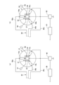
- FIG. 8 is a cross-sectional view taken along the line S9-S9 in FIG.
- FIG. 1 is a configuration diagram of the electric power steering device of the first embodiment.
- the steering mechanism 1 steers the front wheels 3 and 3, which are steering wheels, as the steering wheel 2 rotates, and has a rack and pinion type steering gear 4.
- the pinion gear 5 of the steering gear 4 is connected to the steering wheel 2 via the steering shaft 6.
- the rack gear 7 of the steering gear 4 is provided on the rack shaft 8 extending in the vehicle width direction. Both ends of the rack shaft 8 are connected to the front wheels 3 and 3 via tie rods 9 and 9.
- a three-phase brushless DC motor (a motor unit, hereinafter referred to as a motor) 11 is connected to the steering shaft 6 via a speed reducer 10.
- the motor 11 has a motor rotor 12 and a stator coil 13.
- the motor rotor 12 is a magnet and is provided integrally with the motor shaft 14. Details of the stator coil 13 will be described later.
- the speed reducer 10 has a worm shaft 15 and a worm wheel 16.
- the worm shaft 15 is provided integrally with the motor shaft 14.
- the rotational torque from the motor shaft 14 is transmitted to the steering shaft 6 via the reducer 10.
- the steering shaft 6 is provided with a torque sensor 17 that detects the steering torque.
- the EPS assist controller 18 controls the drive current of the motor 11 based on the steering torque detected by the torque sensor 17 and the vehicle speed detected by the vehicle speed sensor 19, and assists the steering mechanism 1 in steering the driver. The steering force of is given.
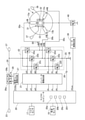
- FIG. 2 is a circuit configuration diagram of the motor drive device of the first embodiment.
- the EPS assist controller 18 includes a microcomputer 20, an inverter drive circuit 21, and an inverter 22 as motor drive devices.
- the motor drive command signal generation unit 201 of the microcomputer 20 applies each FET (field effect) of the inverter 22 to the inverter drive circuit 21 based on the PWM control law so that the output of the motor 11 according to the steering torque and the vehicle speed can be obtained.
- Transistor Motor drive command signals (switching signals) uH, vH, wH, uL, vL, wL for driving and controlling 22a to 22f are output.
- the inverter drive circuit 21 is a pre-driver and outputs the motor drive command signals uH, vH, wH, uL, vL, wL output from the microcomputer 20 and amplifies the signals UH, VH, WH, UL, VL, WL. Output to each FET 22a to 22f of the inverter 22.
- Inverter 22 is a bridge circuit having 6 FETs 22a to 22f. Each of the FETs 22a to 22f operates in response to the motor drive command signals UH, VH, WH, UL, VL, and WL amplified by the inverter drive circuit 21, and applies a voltage to the stator coil 13 of the motor 11.
- the upper arms 22a to 22c are connected to the battery 23 by a power line 24.
- the lower arms 22d to 22f are connected to the ground wire 25.
- the power supply line 24 is provided with a power supply relay 26.
- the power relay 26 has two FETs 26a and 26b.
- the power relay control unit 20a of the microcomputer 20 outputs a relay drive command signal Vrelay for driving and controlling each of the FETs 26a and 26b to the power relay drive circuit 27.
- the power relay drive circuit 27 is a pre-driver that amplifies the relay drive command signal Vrelay output from the microcomputer 20 and outputs it to each of the FETs 26a and 26b.
- a current sensor (shunt resistor) 28 is provided on the ground wire 25. The current sensor 28 detects the phase current (each current value of the U phase, the V phase, and the W phase) of the stator coil 13.
- the output signal i of the current sensor 28 is amplified by the current sensor amplifier 29 and input to the microcomputer 20.
- the stator coil 13 has a U-phase (first phase) coil 13a, a V-phase (second-phase) coil 13b, and a W-phase (third-phase) coil 13c star-connected.
- the stator coil 13 rotates and drives the motor rotor 12 according to the voltage applied to each phase.
- the inverter 22 and the stator coil 13 are connected via a connection circuit 30.
- the connection circuit 30 is three conductive wires extending from the stator coil 13 in the direction of the rotation axis of the motor rotor 12.
- the U-phase conductive wire 30a connects the first transistor 22a and the second transistor 22d, which are connected in series with each other, and the U-phase coil 13a.
- the V-phase conductive wire 30b connects the third transistor 22b and the fourth transistor 22e, which are connected in series with each other, and the V-phase coil 13b.
- the W-phase conductive wire 30c connects the fifth transistor 22c and the sixth transistor 22f, which are connected in series with each other, and the W-phase coil 13c.
- the motor drive device of the first embodiment is provided with a heater integrated fuse 31 with the aim of suppressing the brake torque in the event of a short circuit failure of the inverter 22.
- a short-circuit failure is a failure in which the source and drain are short-circuited in any one of the FETs constituting the inverter.
- the heater integrated fuse 31 has a fuse element 32 and a heater unit 33.
- the fuse element 32 is provided at the neutral point of the stator coil 13.
- the heater unit 33 generates heat by the electric power from the fuse heating power supply 37, and the fuse element 32 can be cut (blown) by the heat generation.
- the fuse heating power supply 37 connects between the power supply relay 26 and the inverter 22 in the power supply line 24 and the heater unit 33, and supplies electric power from the battery 23 to the heater unit 33.
- a voltage sensor 38 is provided at the neutral point of the stator coil 13. The voltage sensor 38 detects the voltage at the neutral point and outputs it to the microcomputer 20. The details of the heater integrated fuse 31 will be described later.
- the microcomputer 20 has a failure detection unit 20b and a heater control unit 20c in addition to the motor drive command signal generation unit 201 and the power relay control unit 20a.
- the failure detection unit 20b detects a short-circuit failure of the inverter 22 based on the change in the voltage at the neutral point detected by the voltage sensor 38. If any of the upper arms 22a to 22c of the six FETs 22a to 22f connected to the bridge of the inverter 22 fails in a short circuit, the voltage at the neutral point of the stator coil 13 rises. Therefore, by detecting the rise in the voltage at the neutral point, it is possible to detect a short-circuit failure of the FETs 22a to 22c. Further, since the voltage at the neutral point becomes 0 after the fuse element 22 is blown, it can be confirmed that the fuse element 32 has been blown by detecting this change.
- the heater control unit 20c When the failure detection unit 20b detects a short-circuit failure of the inverter 22, the heater control unit 20c outputs a heater energization command signal Vfuse for driving and controlling the FET 40 to the heater drive circuit 39.
- the heater drive circuit 39 is a pre-driver that amplifies the heater energization command signal Vfuse output from the microcomputer 20 and outputs it to the FET 40.
- the heater energization command signal Vfuse When the heater energization command signal Vfuse is input to the FET 40, power is supplied from the fuse heating power supply 37 to the heater unit 33.
- the power relay control unit 20a switches the power relay 26 to the cutoff state so as to cut off the continuity between the battery 23 and the inverter 22.
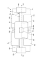
- FIG. 3 is a front view of the heater integrated fuse 31 of the first embodiment
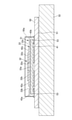
- FIG. 4 is a cross-sectional view taken along the line S4-S4 of FIG.
- the heater-integrated fuse 31 is mounted on the fuse element mounting substrate 50 and is covered with the fuse element case 50a.
- the fuse element mounting substrate 50 is installed inside the motor housing (aluminum housing) 52 via the copper film 51.
- the fuse element mounting substrate 50 is a glass epoxy substrate obtained by impregnating a glass fiber cloth with an epoxy resin and performing a thermosetting treatment.
- the motor housing 52 is made of aluminum alloy and houses the motor rotor 12 and the stator coil 13.
- the heater integrated fuse 31 has a substrate 41.
- the substrate 41 has a U-phase terminal 42a, a V-phase terminal 42b, a W-phase terminal 42c, a neutral point potential extraction terminal 42d, a first power supply terminal (first electrode portion) 43a, and a second power supply terminal (second electrode portion). ) 43b is provided.
- the terminals 42a to 42d, 43a, and 43b are mounted on the fuse element mounting substrate 50 via the element soldering land 53.
- the U-phase terminal 42a is connected to the U-phase coil 13a.
- the V-phase terminal 42b is connected to the V-phase coil 13b.
- the W-phase terminal 42c is connected to the W-phase coil 13c.
- the neutral point potential extraction terminal 42d is connected to the voltage sensor 38.
- the electric resistance value of the neutral point potential extraction terminal 42d is larger than the electric resistance values of the U-phase coil 13a, the V-phase coil 13b, the W-phase coil 13c, the U-phase terminal 42c, the V-phase terminal 42b, and the W-phase terminal 42c. It is set.
- the electric resistance value of the neutral point potential extraction terminal 42d is, for example, 1 k ⁇ .
- the first power supply terminal 43a is connected to the fuse heating power supply 37.
- the second power supply terminal 43b is connected to the FET 40.
- Each terminal 42a to 42d, 43a, 43b is formed in a U shape by bending a metal plate, and is fixed to the substrate 41 with both ends sandwiching both sides of the substrate 41.
- the U-phase terminal 42a and the W-phase terminal 42c are arranged on one end side of the short side of the substrate 41.
- the V-phase terminal 42b and the neutral point potential extraction terminal 42d are arranged on the other end side of the short side of the substrate 41.
- the first power supply terminal 43a is arranged on one end side of the long side of the board 41, and the second power supply terminal 43b is arranged on the other end side of the long side of the board 41.
- the terminals 42a to 43d, 43a, and 43b are arranged apart from each other.
- the fuse element 32 is formed in a substantially rectangular shape in a front view using, for example, a soluble metal such as solder (an alloy containing lead and tin as main components).
- the fuse element 32 is provided on each terminal 42a to 42d.
- a through hole 32a is formed in the center of the front view of the fuse element 32. Flux is applied to the surface of the fuse element 32.
- the fuse element 32 has a first connection portion 32b, a second connection portion 32c, a third connection portion 32d, and a fourth connection portion 32e.
- the first connection portion 32b connects the U-phase terminal 42a and the V-phase terminal 42b.
- the second connection portion 32c connects the U-phase terminal 42a and the W-phase terminal 42c.
- the third connection portion 32d connects the V-phase terminal 42b and the neutral point potential extraction terminal 42d.
- the fourth connection portion 32e connects the W phase terminal 42c and the neutral point potential extraction terminal 42d.
- the heater portion 33 is fixed to the side of both sides of the substrate 41 where the fuse element 32 is provided.
- the heater portion 33 is provided between the substrate 41 and the terminals 42a to 42d, 43a, 43b.
- a gap space is formed between the heater portion 33 and the fuse element 32 by the plate thickness of each terminal 42a to 42d. Therefore, the heater portion 33 and the fuse element 32 are arranged apart from each other.
- the heater portion 33 has a base portion 33a, a first crossing portion 33b, a second crossing portion 33c, a first branch portion 33d, and a second branch portion 33e, and is formed in a front view cross shape.
- the base portion 33a is located at the center of the heater portion 33 and is arranged at a position facing the through hole 32a of the fuse element 32.
- the first crossing portion 33b extends from the base portion 33a toward one end of the long side of the substrate 41 and connects to the first power supply terminal 43a.
- the first crossing portion 33b is provided between the U-phase terminal 42a and the V-phase terminal 42b so as to be separated from both terminals 42a and 42b.
- the first connection portion 32b of the fuse element 32 connects the U-phase terminal 32a and the V-phase terminal 42b so as to straddle the first cross-section portion 33b.
- the second crossing portion 33c extends from the base portion 33a toward the other end of the long side of the substrate 41 and connects to the second power supply terminal 43b.
- the second crossing portion 33c is provided between the W phase terminal 42c and the neutral point potential extraction terminal 42d so as to be separated from both terminals 42c and 42d.
- the fourth connecting portion 32e of the fuse element 32 connects the W phase terminal 42c and the neutral point potential extraction terminal 42d so as to straddle the second crossing portion 33c.
- the first branch portion 33d extends from the base portion 33a toward one end of the short side of the substrate 41.
- the first branch portion 33d is provided between the U-phase terminal 42a and the W-phase terminal 42c, separated from both terminals 42a and 42c.
- the first branch portion 33d is provided so as to extend to the outside (one end side of the short side of the substrate 41) from the second connection portion 32c.
- the third connection portion 32c of the fuse element 32 connects the U-phase terminal 42a and the W-phase terminal 42c so as to straddle the first branch portion 33d.
- the second branch portion 33e extends from the base portion 33a toward the other end of the short side of the substrate 41.
- the second branch portion 33e is provided between the V-phase terminal 42b and the neutral point potential extraction terminal 42d so as to be separated from both terminals 42b and 42d.
- the second branch portion 33e is provided so as to extend to the outside (the other end side of the short side of the substrate 41) from the third connection portion 32d.
- the second connection portion 32d of the fuse element 32 connects the V-phase terminal 42b and the neutral point potential extraction terminal 42d so as to straddle the second branch portion 33e.
- the U-phase terminal 42a is separated from the first crossing portion 33b along the extending direction of the first branch portion 33d (the direction from the other end side of the short side of the substrate 41 toward one end side). Extend along.
- the V-phase terminal 42b extends along a direction in which the second branch portion 33e extends (direction from one end side of the short side of the substrate 41 toward the other end side) and away from the first cross section 33b.
- the W phase terminal 42c extends along the direction in which the first branch portion 33d extends and in the direction away from the second cross section 33c.
- the neutral point potential extraction terminal 42d extends along the extending direction of the second branching portion 33e and along the direction away from the second crossing portion 33c.
- the semiconductor relay provided in the connection circuit connecting the inverter and the stator coil is cut off, so that a closed circuit including the motor winding of the failed phase is included. Is prevented from being formed and the generation of brake torque is suppressed.
- a semiconductor relay since a semiconductor relay has a relatively large resistance value, its power loss causes a decrease in motor efficiency.
- the motor drive device of the first embodiment detects a short-circuit failure of the inverter 22, it heats the heater portion 33 of the heater integrated fuse 31.
- the first connection portion 32b, the second connection portion 32c, the third connection portion 32d, and the fourth connection portion 32e of the fuse element 32 are blown, and electricity between the terminals 42a and 42d is generated.
- the connection is cut off. That is, by using the heater integrated fuse 31 as a relay for shutting off the closed circuit, the resistance value can be reduced as compared with the case of using a semiconductor relay or a relay of other electronic components, so that the power consumption can be suppressed.
- the fuse element 32 of the first embodiment is provided at the neutral point of the stator coil 13. That is, the structure of the heater integrated fuse 31 can be simplified by adopting a structure that cuts the neutral point instead of cutting each phase of the stator coil 13. In addition, the resistance value is smaller than when a semiconductor relay or a relay of an electronic component is used, and power consumption can be suppressed.
- the heater-integrated fuse 31 includes a neutral point potential extraction terminal 42d for measuring the potential of the neutral point, and the neutral point potential extraction terminal 42d is connected to the fuse element 32 and is connected to the fuse element 32. Is cut off, the continuity between the neutral point potential extraction terminal 42d and the stator coil 13 is cut off. This can also be applied to a structure that measures the neutral point potential in order to detect a short-circuit failure of the inverter 22, and the neutral point potential is taken out by the same fuse element as the fuse element 32 that cuts the continuity of the stator coil 13. The continuity between the terminal 42d and the stator coil 13 can also be cut.
- the electric resistance value of the neutral point potential extraction terminal 42d is larger than the electric resistance values of the U-phase coil 13a, the V-phase coil 13b, and the W-phase coil 13c.
- the neutral point potential extraction terminal 42d has a ground fault
- current may be concentrated and flow through the neutral point potential extraction terminal 42d, causing the device to become overheated. Therefore, by making the electric resistance value of the neutral point potential extraction terminal 42d larger than the electric resistance value of each phase of the stator coil 13, the device in the case where the neutral point potential extraction terminal 42d has a ground fault. Overheating can be suppressed.
- the heater portion 33 has a first crossing portion 33b provided between the U phase terminal 42a and the V phase terminal 42b, and the fuse element 32 has the U phase terminal 42a and the V phase so as to straddle the first crossing portion 33b. It has a first connection portion 32b for connecting to the terminal 42b. As a result, the portion of the fuse element 32 that straddles the U-phase terminal 42a and the V-phase terminal 42b is heated by the first crossing portion 33b of the heater portion 33, so that the conduction between the U-phase and the V-phase can be cut more reliably.
- the heater portion 33 has a base portion 33a connected to the first crossing portion 33b and a first branch portion 33d provided so as to branch from the base portion 33a, and the U-phase terminal 42a and the W-phase terminal 42c are first.
- the fuse element 32 is provided so as to sandwich the branch portion 33d, and has a second connection portion 32c that connects the U-phase terminal 42a and the W-phase terminal 42c so as to straddle the first branch portion 33d.
- the fuse element 32 has a through hole 32a formed in a region facing the base 33a. That is, by providing a through hole 32a in a portion (a portion facing the base 33a) which is not always necessary for the purpose of conducting conduction between each phase of the stator coil 13, conduction between each phase when this portion is not fused. It is possible to suppress the occurrence of cutting defects. In addition, the usage fee of the molten metal used as the material of the fuse element 32 can be suppressed.
- the heater portion 33 is provided so as to branch off from the second crossing portion 33c provided between the W phase terminal 42c and the neutral point potential extraction terminal 42d and the base portion 33a, and is provided so as to branch from the V phase terminal 42b and the neutral point potential.
- a second branch 33e provided between the take-out terminals 42d, a first power supply terminal 43a connected to the first cross section 33b and extending to the opposite side of the base 33a, and a base 33a connected to the second cross section 33c.
- a second power supply terminal 43b extending to the opposite side is provided, the U-phase terminal 42a extends along the extending direction of the first branching portion 33d along the direction away from the first crossing portion 33b, and the V-phase terminal 42b extends.
- the W phase terminal 42c extends along the extending direction of the second branching portion 33e and away from the first crossing portion 33b, and the W phase terminal 42c extends along the extending direction of the first branching portion 33d.
- the neutral point potential extraction terminal 42d extends in a direction away from the second branch portion 33e, and extends in a direction away from the second crossing portion 33c along the extending direction of the second branch portion 33e.
- the continuity between the terminals 42a to 42d can be more reliably cut by the first crossing portion 33b, the second crossing portion 33c, the first branch portion 33d, and the second branch portion 33e of the heater portion 33.
- the proximity of each terminal 42a to 42d, 43a, 43b is suppressed, and the risk of short circuit between terminals can be reduced.
- the motor drive device includes a motor housing 52, a copper film 51, and a fuse element mounting substrate 50.
- the heater-integrated fuse 31 is mounted on the fuse element mounting substrate 50, and the fuse element mounting substrate 50 is copper. It is installed in the motor housing 52 via the membrane 51.
- the amount of heat of the heater-integrated fuse 31 can be reduced. It can be released to the motor housing 52 moderately.
- FIG. 6 is a circuit configuration diagram of the stator coil of the second embodiment.
- the stator coil is made redundant.
- the configuration of the portion not shown in FIG. 6 is the same as that of the first embodiment shown in FIG.
- the first stator coil 13 has the same configuration as that of the first embodiment shown in FIG.
- a U-phase (fourth phase) coil 54a, a V-phase (fifth-phase) coil 54b, and a W-phase (sixth-phase) coil 54c are star-connected.
- the inverter 22 and the second stator coil 54 are connected to each other via the second connection circuit 60.
- the U-phase conductive wire 60a of the second connection circuit 60 is connected to the U-phase coil 54a.
- the V-phase conductive wire 60b is connected to the V-phase coil 54b, and the W-phase conductive wire 60c is connected to the W-phase coil 54c.
- the first heater integrated fuse 31 has the same configuration as that of the first embodiment shown in FIG.
- the second heater integrated fuse 55 has a second fuse element 56 and a second heater portion 57.
- the second fuse element 56 is provided at the neutral point of the second stator coil 54.
- the second heater unit 57 generates heat by the electric power from the second fuse heating power source 58, and the second fuse element 56 can be cut (blown) by the heat generation.
- the second fuse heating power supply 58 connects between the power supply relay 26 and the inverter 22 in the power supply line 24 and the second heater unit 57, and supplies electric power from the battery 23 to the second heater unit 57. ..
- a second voltage sensor 59 is provided at the neutral point of the second stator coil 54.
- the second voltage sensor 59 detects the voltage at the neutral point and outputs it to the microcomputer 20.
- the first stator coil 13 and the second stator coil 54 are housed in one housing (motor housing), and a common motor rotor 12 is rotationally driven.
- the heater control unit 20c has a first heater drive circuit 39 or so that power is supplied to the first heater unit 33 or the second heater unit 57 when the failure detection unit detects a short-circuit failure of the inverter 22.
- a heater energization command signal Vfuse for driving and controlling the first FET 40 or the second FET 62 is output to the second heater drive circuit 61.
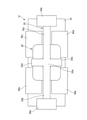
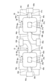
- FIG. 7 is a front view of the first heater integrated fuse 31 and the second heater integrated fuse 55 of the second embodiment.
- the first heater-integrated fuse 31 and the second heater-integrated fuse 55 are both mounted on a common substrate 63.
- a first heater-integrated fuse 31 is arranged on one end side of the long side of the substrate 63, and a second heater-integrated fuse 55 is arranged on the other end side of the long side of the substrate 63.
- the first heater-integrated fuse 31 has the same configuration as that of the first embodiment shown in FIG. 3, except that the second power supply terminal 43b is arranged on one end side of the short side of the substrate 63, but the second one.
- the heater integrated fuse 55 includes a U-phase terminal 64a, a V-phase terminal 64b, a W-phase terminal 64c, a neutral point potential extraction terminal 64d, and a first power supply. It has a terminal 65a and a second power supply terminal 65b.
- the structure and function of the terminals 64a to 64d, 65a, 65b are almost the same as those of the terminals 42a to 42d, 43a, 43b of the first heater integrated fuse 31, but the first power supply terminal 65a is the substrate 63. It is arranged on the other end side of the short side and faces the second power supply terminal 43b of the first heater integrated fuse 31 in the short side direction of the substrate 63.
- the second fuse element 56 has a through hole 56a, a first connection portion 56b, a second connection portion 56c, a third connection portion 56d, and a fourth connection portion 56e.
- the second heater portion 57 has a base portion 57a, a first crossing portion 57b, a second crossing portion 57c, a first branch portion 57d, and a second branch portion 57e, similarly to the first heater portion 33.
- first heater-integrated fuse 31, second heater-integrated fuse 55 when two heater-integrated fuses are provided (first heater-integrated fuse 31, second heater-integrated fuse 55), these two heater-integrated fuses 31, 55 are used as a common substrate. By mounting it on 63, it is possible to improve the layout and assembly of the heater integrated fuse even in a motor drive device in which the stator coils 13 and 54 have a so-called redundant configuration.
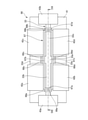
- FIG. 8 is a front view of the heater integrated fuse 66 of the third embodiment
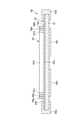
- FIG. 9 is a cross-sectional view taken along the line S9-S9 of FIG.
- the fuse element 67 is provided on the heater portion 33, and its side surface is in contact with the end faces of the terminals 42a to 42d.
- the fuse element 67 is formed in a square frame shape in front view, and has a first connection portion 67a, a second connection portion 67b, a third connection portion 67c, and a fourth connection portion 67d.
- the functions of the connection portions 67a to 67d are the same as those of the connection portions 42b to 42e in the fuse element 32 of the first embodiment.
- the first crossing portion 33b has a first wall portion 68a.
- the first wall portion 68a is provided on one end side of the long side of the substrate 41 with respect to the first connection portion 67a of the fuse element 67.
- a first insulating material 69a is interposed between the first wall portion 68a and the first connecting portion 67a.
- the second cross section 33c has a second wall portion 68b.
- the second wall portion 68b is provided on the other end side of the long side of the substrate 41 with respect to the fourth connection portion 67d of the fuse element 67.
- a second insulator 69b is interposed between the second wall portion 68b and the fourth connecting portion 67d.
- the first branch portion 33d has a third wall portion 68c.
- the third wall portion 68c is provided on one end side of the short side of the substrate 41 with respect to the second connection portion 67b of the fuse element 67.
- a third insulator 69c is interposed between the third wall portion 68c and the second connecting portion 67b.
- the second branch portion 33e has a fourth wall portion 68d.
- the fourth wall portion 68d is provided on the other end side of the short side of the substrate 41 with respect to the third connection portion 67c of the fuse element 67.
- a fourth insulator 69d is interposed between the fourth wall portion 68d and the third connection portion 67c.
- As each of the insulators 69a to 69d for example, silicon-based insulating grease or mica is used.
- the specific configuration of the present invention is not limited to the configurations of the embodiments, and there are design changes and the like within a range that does not deviate from the gist of the invention. Is also included in the present invention.
- the stator coil is not limited to three phases, and may have three or more phases.
- the terminal for taking out the neutral point potential may be formed of a material having a large electric resistance value, or the surface of the terminal for taking out the neutral point potential may be formed. It may be coated with a material having a large electric resistance value.
- the circumference of the through hole of the fuse element does not necessarily have to be connected in an annular shape, and may be connected in a C shape and may have a shape in which a part thereof is cut off. Inverter short-circuit failure may be detected based on the changes in the U-phase, V-phase, and W-phase currents of the stator coil.
- the motor drive device of the present invention can be applied to other than the electric power steering, and has the same effect as that of the embodiment.
- the motor drive device is a motor unit having a motor rotor and a stator coil, wherein the stator coils are of the first phase, the second phase, and the third phase, which are star-connected to each other.
- the motor unit including the coil, the inverter that drives and controls the motor unit, and the first heater-integrated fuse provided in the stator coil, the first heater-integrated fuse is the stator coil.
- the first heater integrated fuse including the first fuse element provided at the neutral point and the first heater portion that generates heat for cutting the first fuse element, and the motor drive.
- a microcomputer having a command signal generation unit, a failure detection unit, and a heater control unit, wherein the motor drive command signal generation unit generates a motor drive command signal for driving and controlling the inverter, and the motor drive command signal is generated.
- the failure detection unit detects a short-circuit failure of the inverter, and the heater control unit supplies power to the first heater unit when the failure detection unit detects a short-circuit failure of the inverter.
- the microcomputer for outputting a heater energization command signal.
- the neutral point potential extraction terminal for measuring the potential of the neutral point is further provided, and the neutral point potential extraction terminal is connected to the first fuse element.
- the electrical resistance value of the neutral point potential extraction terminal is higher than the electrical resistance value of the coils of the first phase, the second phase, and the third phase. big.
- the first heater section has a first cross section provided between the first phase and the second phase, said first.
- the fuse element has a first connecting portion that connects the first phase and the second phase so as to straddle the first crossing portion.
- the first heater portion comprises a base connected to the first cross section and a first branch provided so as to branch from the base.
- the first phase and the third phase are provided so as to sandwich the first branch portion, and the first fuse element straddles the first branch portion. It has a second connection portion for connecting the third phase and the third phase.
- the end portion on the side far from the base portion is provided so as to extend to the outside of the second connection portion. Has been done.
- the first fuse element has a through hole formed in a region facing the base.
- the neutral point potential extraction terminal for measuring the potential of the neutral point is further provided, and the neutral point potential extraction terminal is the first.
- the first heater portion which is connected to the fuse element of the above, is connected to the base portion, and has a second crossing portion provided between the third phase and the neutral point potential extraction terminal.
- a second branch portion provided so as to branch from the base portion and provided between the second phase and the neutral point potential extraction terminal, and a second branch portion connected to the first cross section and on the opposite side of the base portion. It includes a first electrode portion that extends, and a second electrode portion that is connected to the second cross section and extends to the opposite side of the base portion.
- the first phase extends along the extending direction of the first branch portion in a direction away from the first crossing portion, and the second phase extends along the extending direction of the second branch portion.
- the third phase extends along a direction away from the first cross section, and the third phase extends along a direction away from the second cross section along the extending direction of the first branch.
- the neutral point potential extraction terminal extends along the extending direction of the second branch portion and along the direction away from the second crossing portion. In still another preferred embodiment, in any of the above embodiments, the neutral point potential extraction terminal for measuring the potential of the neutral point is further provided, and the neutral point potential extraction terminal is the first.
- the motor unit is a three-phase brushless motor, the first phase is the U phase, the second phase is the V phase, and the third phase is W.
- the first heater portion is a phase, which is connected to the base portion and branches from the second crossing portion provided between the W phase and the neutral point potential extraction terminal and the base portion. It has a second branch portion provided between the V phase and the neutral point potential extraction terminal.
- the first fuse element and the first heater portion have a gap space between the first fuse element and the first heater portion. They are arranged apart from each other so that they are formed.
- the surface of the first fuse element is coated with flux.
- the stator coil further comprises a substrate and a second heater integrated fuse, wherein the stator coils are further star-connected to the fourth, fifth, and fifth phases.
- the second heater integrated fuse includes a second fuse element provided at the neutral point of the fourth phase, the fifth phase, and the sixth phase, and the said.
- the first heater-integrated fuse and the second heater-integrated fuse are both mounted on the common substrate, including a second heater portion for cutting the second fuse element.
- the heater control unit outputs a heater energization command signal so that power is supplied to the first heater unit or the second heater unit when the failure detection unit detects a short-circuit failure of the inverter. Output.
- the first heater integrated fuse is mounted on the substrate, further comprising an aluminum housing, a copper film, and a substrate. , It is installed in the aluminum housing via the copper film.
- the heater-integrated fuse is, in one embodiment, a heater-integrated fuse provided in the stator coil of the motor, wherein the motor has a motor rotor and a stator coil, and the stator coils are mutual.
- the present invention is not limited to the above-described embodiment, and includes various modifications.
- the above-described embodiment has been described in detail in order to explain the present invention in an easy-to-understand manner, and is not necessarily limited to the one including all the described configurations.
- it is possible to replace a part of the configuration of one embodiment with the configuration of another embodiment and it is also possible to add the configuration of another embodiment to the configuration of one embodiment.
Landscapes
- Engineering & Computer Science (AREA)
- Power Engineering (AREA)
- Chemical & Material Sciences (AREA)
- Combustion & Propulsion (AREA)
- Microelectronics & Electronic Packaging (AREA)
- Transportation (AREA)
- Mechanical Engineering (AREA)
- Power Steering Mechanism (AREA)
- Inverter Devices (AREA)
- Fuses (AREA)
- Control Of Ac Motors In General (AREA)
Abstract
ステータコイルの中性点に設けられた第1のヒューズエレメントと、第1のヒューズエレメントを切断するために発熱する第1のヒータ部と、を含む第1のヒータ一体型ヒューズが、ステータコイルに設けられ、マイクロコンピュータは、インバータのショート故障を検知した場合に、第1のヒータ部に電力が供給されるように、ヒータ通電指令信号を出力する。
Description
本発明は、モータ駆動装置およびヒータ一体型ヒューズに関する。
特許文献1には、インバータのショート故障時におけるブレーキトルクを抑制することを目的とし、インバータとステータコイルとを接続する接続回路に半導体リレーを設けたモータ駆動装置が開示されている。
しかしながら、上記従来技術にあっては、半導体リレーは比較的抵抗値が大きいため、消費電力が増大するおそれがあった。
本発明の目的の一つは、電力消費量を抑制できるモータ駆動装置を提供することにある。
本発明の一実施形態におけるモータ駆動装置は、ステータコイルの中性点に設けられた第1のヒューズエレメントと、第1のヒューズエレメントを切断するために発熱する第1のヒータ部と、を含む第1のヒータ一体型ヒューズが、ステータコイルに設けられ、マイクロコンピュータは、インバータのショート故障を検知した場合に、第1のヒータ部に電力が供給されるように、ヒータ通電指令信号を出力する。
本発明の一実施形態におけるモータ駆動装置は、ステータコイルの中性点に設けられた第1のヒューズエレメントと、第1のヒューズエレメントを切断するために発熱する第1のヒータ部と、を含む第1のヒータ一体型ヒューズが、ステータコイルに設けられ、マイクロコンピュータは、インバータのショート故障を検知した場合に、第1のヒータ部に電力が供給されるように、ヒータ通電指令信号を出力する。
本発明の一実施形態によれば、電力消費量を抑制できる。
〔実施形態1〕
図1は、実施形態1の電動パワーステアリング装置の構成図である。
操舵機構1は、ステアリングホイール2の回転に伴い、転舵輪である前輪3,3を転舵させるもので、ラック&ピニオン式のステアリングギア4を有する。ステアリングギア4のピニオンギア5は、ステアリングシャフト6を介してステアリングホイール2と連結されている。ステアリングギア4のラックギア7は、車幅方向に延びるラック軸8に設けられている。ラック軸8の両端は、タイロッド9,9を介して前輪3,3と連結されている。ステアリングシャフト6には、減速機10を介して3相ブラシレスDCモータ(モータ部であって、以下、モータと称す。)11が連結されている。
図1は、実施形態1の電動パワーステアリング装置の構成図である。
操舵機構1は、ステアリングホイール2の回転に伴い、転舵輪である前輪3,3を転舵させるもので、ラック&ピニオン式のステアリングギア4を有する。ステアリングギア4のピニオンギア5は、ステアリングシャフト6を介してステアリングホイール2と連結されている。ステアリングギア4のラックギア7は、車幅方向に延びるラック軸8に設けられている。ラック軸8の両端は、タイロッド9,9を介して前輪3,3と連結されている。ステアリングシャフト6には、減速機10を介して3相ブラシレスDCモータ(モータ部であって、以下、モータと称す。)11が連結されている。
モータ11は、モータロータ12とステータコイル13とを有する。モータロータ12は、マグネットであって、モータシャフト14と一体に設けられている。ステータコイル13の詳細は後述する。減速機10は、ウォームシャフト15とウォームホイール16とを有する。ウォームシャフト15は、モータシャフト14と一体に設けられている。モータシャフト14からの回転トルクは、減速機10を介してステアリングシャフト6に伝達される。ステアリングシャフト6には、操舵トルクを検出するトルクセンサ17が設けられている。EPSアシストコントローラ18は、トルクセンサ17により検出された操舵トルクと、車速センサ19により検出された車速とに基づいてモータ11の駆動電流を制御し、操舵機構1に対しドライバの操舵をアシストするための操舵力を付与する。
図2は、実施形態1のモータ駆動装置の回路構成図である。
EPSアシストコントローラ18は、モータ駆動装置として、マイクロコンピュータ20、インバータ駆動回路21およびインバータ22を備える。
マイクロコンピュータ20のモータ駆動指令信号生成部201は、操舵トルクおよび車速に応じたモータ11の出力が得られるよう、PWM制御則に基づき、インバータ駆動回路21に対し、インバータ22の各FET(電界効果トランジスタ)22a~22fを駆動制御するためのモータ駆動指令信号(スイッチング信号)uH,vH,wH,uL,vL,wLを出力する。
インバータ駆動回路21は、プリドライバであって、マイクロコンピュータ20から出力されたモータ駆動指令信号uH,vH,wH,uL,vL,wLを増幅した信号UH,VH,WH,UL,VL,WLをインバータ22の各FET22a~22fに出力する。
インバータ22は、6個のFET22a~22fを有するブリッジ回路である。各FET22a~22fは、インバータ駆動回路21によって増幅されたモータ駆動指令信号UH,VH,WH,UL,VL,WLに応じて動作し、モータ11のステータコイル13に電圧を印加する。上アーム22a~22cは、バッテリ23と電源線24で接続されている。下アーム22d~22fは、グランド線25と接続されている。電源線24には、電源リレー26が設けられている。電源リレー26は、2個のFET26a,26bを有する。マイクロコンピュータ20の電源リレー制御部20aは、電源リレー駆動回路27に対し、各FET26a,26bを駆動制御するためのリレー駆動指令信号Vrelayを出力する。電源リレー駆動回路27は、プリドライバであって、マイクロコンピュータ20から出力されたリレー駆動指令信号Vrelayを増幅して各FET26a,26bに出力する。グランド線25には、電流センサ(シャント抵抗)28が設けられている。電流センサ28は、ステータコイル13の相電流(U相、V相およびW相のそれぞれの電流値)を検出する。電流センサ28の出力信号iは、電流センサアンプ29により増幅されてマイクロコンピュータ20に入力される。
ステータコイル13は、U相(第1相)コイル13a、V相(第2相)コイル13bおよびW相(第3相)コイル13cがスター結線されている。ステータコイル13は、各相に印加される電圧に応じてモータロータ12を回転駆動させる。インバータ22とステータコイル13とは、接続回路30を介して接続されている。接続回路30は、モータロータ12の回転軸線の方向においてステータコイル13から延びる3本の導電線である。U相用導電線30aは、互いに直列に接続された第1トランジスタ22aおよび第2トランジスタ22dと、U相コイル13aとを接続する。V相用導電線30bは、互いに直列に接続された第3トランジスタ22bおよび第4トランジスタ22eと、V相コイル13bとを接続する。W相導電線30cは、互いに直列に接続された第5トランジスタ22cおよび第6トランジスタ22fと、W相コイル13cとを接続する。
実施形態1のモータ駆動装置は、インバータ22のショート故障時におけるブレーキトルクを抑制することを狙いとし、ヒータ一体型ヒューズ31を備える。ショート故障とは、インバータを構成する各FETのいずれかにおいて、ソース-ドレイン間が短絡する故障である。
ヒータ一体型ヒューズ31は、ヒューズエレメント32と、ヒータ部33とを有する。ヒューズエレメント32は、ステータコイル13の中性点に設けられている。ヒータ部33は、ヒューズ加熱用電源37からの電力により発熱し、発熱によりヒューズエレメント32を切断(溶断)可能である。ヒューズ加熱用電源37は、電源線24における電源リレー26とインバータ22との間と、ヒータ部33とを接続し、バッテリ23からヒータ部33に電力を供給する。ステータコイル13の中性点には、電圧センサ38が設けられている。電圧センサ38は、中性点の電圧を検出し、マイクロコンピュータ20へ出力する。ヒータ一体型ヒューズ31の詳細については後述する。
ヒータ一体型ヒューズ31は、ヒューズエレメント32と、ヒータ部33とを有する。ヒューズエレメント32は、ステータコイル13の中性点に設けられている。ヒータ部33は、ヒューズ加熱用電源37からの電力により発熱し、発熱によりヒューズエレメント32を切断(溶断)可能である。ヒューズ加熱用電源37は、電源線24における電源リレー26とインバータ22との間と、ヒータ部33とを接続し、バッテリ23からヒータ部33に電力を供給する。ステータコイル13の中性点には、電圧センサ38が設けられている。電圧センサ38は、中性点の電圧を検出し、マイクロコンピュータ20へ出力する。ヒータ一体型ヒューズ31の詳細については後述する。
マイクロコンピュータ20は、モータ駆動指令信号生成部201および電源リレー制御部20aに加えて、故障検知部20bおよびヒータ制御部20cを有する。
故障検知部20bは、電圧センサ38により検出された中性点の電圧の変化に基づき、インバータ22のショート故障を検知する。インバータ22のブリッジ接続されている6個のFET22a~22fのうち、上アーム22a~22cのいずれかがショート故障した場合、ステータコイル13の中性点の電圧が上昇する。よって、この中性点の電圧の上昇を検知することにより、FET22a~22cのショート故障を検知できる。また、ヒューズエレメント22を切断した後は、中性点の電圧が0になるため、この変化を検出することにより、ヒューズエレメント32が切断されたことを確認できる。
故障検知部20bは、電圧センサ38により検出された中性点の電圧の変化に基づき、インバータ22のショート故障を検知する。インバータ22のブリッジ接続されている6個のFET22a~22fのうち、上アーム22a~22cのいずれかがショート故障した場合、ステータコイル13の中性点の電圧が上昇する。よって、この中性点の電圧の上昇を検知することにより、FET22a~22cのショート故障を検知できる。また、ヒューズエレメント22を切断した後は、中性点の電圧が0になるため、この変化を検出することにより、ヒューズエレメント32が切断されたことを確認できる。
ヒータ制御部20cは、故障検知部20bがインバータ22のショート故障を検知するとき、ヒータ駆動回路39に対し、FET40を駆動制御するためのヒータ通電指令信号Vfuseを出力する。ヒータ駆動回路39は、プリドライバであって、マイクロコンピュータ20から出力されたヒータ通電指令信号Vfuseを増幅してFET40に出力する。FET40にヒータ通電指令信号Vfuseが入力されると、ヒューズ加熱用電源37からヒータ部33に電力が供給される。
電源リレー制御部20aは、ヒータ制御部20cがヒータ通電指令信号Vfuseを出力した後、バッテリ23とインバータ22との間の導通を遮断するように、電源リレー26を遮断状態に切り替える。
電源リレー制御部20aは、ヒータ制御部20cがヒータ通電指令信号Vfuseを出力した後、バッテリ23とインバータ22との間の導通を遮断するように、電源リレー26を遮断状態に切り替える。
図3は実施形態1のヒータ一体型ヒューズ31の正面図、図4は図3のS4-S4線矢視断面図である。
ヒータ一体型ヒューズ31は、ヒューズ素子実装基板50上に搭載され、ヒューズ素子ケース50aで覆われている。ヒューズ素子実装基板50は、銅膜51を介してモータハウジング(アルミハウジング)52の内部に設置されている。ヒューズ素子実装基板50は、ガラス繊維の布にエポキシ樹脂を染み込ませ熱硬化処理を施したガラスエポキシ基板である。モータハウジング52はアルミ合金製であり、モータロータ12およびステータコイル13を収容する。
ヒータ一体型ヒューズ31は、基板41を有する。基板41には、U相端子42a、V相端子42b、W相端子42c、中性点電位取り出し用端子42d、第1電源端子(第1電極部)43aおよび第2電源端子(第2電極部)43bが設けられている。各端子42a~42d、43a,43bは、素子ハンダ用ランド53を介してヒューズ素子実装基板50上に実装されている。U相端子42aは、U相コイル13aと接続されている。V相端子42bは、V相コイル13bと接続されている。W相端子42cは、W相コイル13cと接続されている。中性点電位取り出し用端子42dは、電圧センサ38と接続されている。中性点電位取り出し用端子42dの電気抵抗値は、U相コイル13a、V相コイル13b、W相コイル13c、U相端子42c、V相端子42bおよびW相端子42cの電気抵抗値よりも大きく設定されている。中性点電位取り出し用端子42dの電気抵抗値は、例えば1kΩとする。第1電源端子43aは、ヒューズ加熱用電源37と接続されている。第2電源端子43bは、FET40と接続されている。
各端子42a~42d,43a,43bは、金属板を折り曲げてコ字状に形成され、両端部が基板41の両面を挟んだ状態で基板41に固定されている。U相端子42aおよびW相端子42cは、基板41の短辺一端側に配置されている。V相端子42bおよび中性点電位取り出し用端子42dは、基板41の短辺他端側に配置されている。第1電源端子43aは、基板41の長辺一端側に配置され、第2電源端子43bは、基板41の長辺他端側に配置されている。各端子42a~43d、43a,43bは、互いに離間して配置されている。
ヒューズエレメント32は、例えば、はんだ(鉛と錫を主成分とした合金)等の可溶性金属を用いて正面視略矩形状に形成されている。ヒューズエレメント32は、各端子42a~42d上に設けられている。ヒューズエレメント32の正面視中央には、貫通穴32aが形成されている。ヒューズエレメント32の表面には、フラックスが塗布されている。ヒューズエレメント32は、第1接続部32b、第2接続部32c、第3接続部32dおよび第4接続部32eを有する。第1接続部32bは、U相端子42aとV相端子42bとを接続する。第2接続部32cは、U相端子42aとW相端子42cとを接続する。第3接続部32dは、V相端子42bと中性点電位取り出し用端子42dとを接続する。第4接続部32eは、W相端子42cと中性点電位取り出し用端子42dとを接続する。ヒューズエレメント32が切断されるとき、各端子42a~42d間の導通は切断される。よって、ヒューズエレメント32が切断されるとき、中性点電位取り出し用端子42dとステータコイル13との間の導通が切断される。
ヒューズエレメント32は、例えば、はんだ(鉛と錫を主成分とした合金)等の可溶性金属を用いて正面視略矩形状に形成されている。ヒューズエレメント32は、各端子42a~42d上に設けられている。ヒューズエレメント32の正面視中央には、貫通穴32aが形成されている。ヒューズエレメント32の表面には、フラックスが塗布されている。ヒューズエレメント32は、第1接続部32b、第2接続部32c、第3接続部32dおよび第4接続部32eを有する。第1接続部32bは、U相端子42aとV相端子42bとを接続する。第2接続部32cは、U相端子42aとW相端子42cとを接続する。第3接続部32dは、V相端子42bと中性点電位取り出し用端子42dとを接続する。第4接続部32eは、W相端子42cと中性点電位取り出し用端子42dとを接続する。ヒューズエレメント32が切断されるとき、各端子42a~42d間の導通は切断される。よって、ヒューズエレメント32が切断されるとき、中性点電位取り出し用端子42dとステータコイル13との間の導通が切断される。
ヒータ部33は、基板41の両面のうち、ヒューズエレメント32が設けられている側に固定されている。ヒータ部33は、基板41と各端子42a~42d,43a,43bとの間に設けられている。ヒータ部33とヒューズエレメント32との間には、各端子42a~42dの板厚分だけ隙間空間が形成されている。このため、ヒータ部33とヒューズエレメント32とは、互いに離間して配置されている。
ヒータ部33は、基部33a、第1横断部33b、第2横断部33c、第1分岐部33dおよび第2分岐部33eを有し、正面視十字形に形成されている。
基部33aは、ヒータ部33の中心に位置し、ヒューズエレメント32の貫通穴32aと対向する位置に配置されている。
第1横断部33bは、基部33aから基板41の長辺一端側へ延び、第1電源端子43aと接続する。第1横断部33bは、U相端子42aとV相端子42bとの間に、両端子42a,42bと離間して設けられている。ヒューズエレメント32の第1接続部32bは、第1横断部33bを跨ぐようにU相端子32aとV相端子42bとを接続する。
ヒータ部33は、基部33a、第1横断部33b、第2横断部33c、第1分岐部33dおよび第2分岐部33eを有し、正面視十字形に形成されている。
基部33aは、ヒータ部33の中心に位置し、ヒューズエレメント32の貫通穴32aと対向する位置に配置されている。
第1横断部33bは、基部33aから基板41の長辺一端側へ延び、第1電源端子43aと接続する。第1横断部33bは、U相端子42aとV相端子42bとの間に、両端子42a,42bと離間して設けられている。ヒューズエレメント32の第1接続部32bは、第1横断部33bを跨ぐようにU相端子32aとV相端子42bとを接続する。
第2横断部33cは、基部33aから基板41の長辺他端側へ延び、第2電源端子43bと接続する。第2横断部33cは、W相端子42cと中性点電位取り出し用端子42dとの間に、両端子42c,42dと離間して設けられている。ヒューズエレメント32の第4接続部32eは、第2横断部33cを跨ぐようにW相端子42cと中性点電位取り出し用端子42dとを接続する。
第1分岐部33dは、基部33aから基板41の短辺一端側へ延びる。第1分岐部33dは、U相端子42aとW相端子42cとの間に、両端子42a,42cと離間して設けられている。第1分岐部33dは、第2接続部32cよりも外側(基板41の短辺一端側)まで延びるように設けられている。ヒューズエレメント32の第3接続部32cは、第1分岐部33dを跨ぐようにU相端子42aとW相端子42cとを接続する。
第1分岐部33dは、基部33aから基板41の短辺一端側へ延びる。第1分岐部33dは、U相端子42aとW相端子42cとの間に、両端子42a,42cと離間して設けられている。第1分岐部33dは、第2接続部32cよりも外側(基板41の短辺一端側)まで延びるように設けられている。ヒューズエレメント32の第3接続部32cは、第1分岐部33dを跨ぐようにU相端子42aとW相端子42cとを接続する。
第2分岐部33eは、基部33aから基板41の短辺他端側へ延びる。第2分岐部33eは、V相端子42bと中性点電位取り出し用端子42dとの間に、両端子42b,42dと離間して設けられている。第2分岐部33eは、第3接続部32dよりも外側(基板41の短辺他端側)まで延びるように設けられている。ヒューズエレメント32の第2接続部32dは、第2分岐部33eを跨ぐようにV相端子42bと中性点電位取り出し用端子42dとを接続する。
基板41の正面視において、U相端子42aは、第1分岐部33dの延びる方向(基板41の短辺他端側から一端側へ向かう方向)に沿って第1横断部33bから離間する方向に沿って延びる。V相端子42bは、第2分岐部33eの延びる(基板41の短辺一端側から他端側へ向かう方向)方向に沿って第1横断部33bから離間する方向に沿って延びる。W相端子42cは、第1分岐部33dの延びる方向に沿って第2横断部33cから離間する方向に沿って延びる。中性点電位取り出し用端子42dは、第2分岐部33eの延びる方向に沿って第2横断部33cから離間する方向に沿って延びる。
基板41の正面視において、U相端子42aは、第1分岐部33dの延びる方向(基板41の短辺他端側から一端側へ向かう方向)に沿って第1横断部33bから離間する方向に沿って延びる。V相端子42bは、第2分岐部33eの延びる(基板41の短辺一端側から他端側へ向かう方向)方向に沿って第1横断部33bから離間する方向に沿って延びる。W相端子42cは、第1分岐部33dの延びる方向に沿って第2横断部33cから離間する方向に沿って延びる。中性点電位取り出し用端子42dは、第2分岐部33eの延びる方向に沿って第2横断部33cから離間する方向に沿って延びる。
次に、実施形態1の作用効果を説明する。
3相ブラシレスDCモータを駆動するインバータにショート故障が発生すると、モータへの電力供給を停止してマニュアルステアリングに移行する。このとき、インバータとモータ巻線間で、故障した相のステータコイルを含む閉回路が形成されているため、ドライバがステアリングホイールを操作してモータが回転されることにより、故障した相のステータコイルには逆起電力が発生する。この逆起電力により、モータ軸には、ステアリングホイールの動きを妨げるブレーキトルクが発生し、ハンドル操舵が重くなる。
従来のモータ駆動装置では、インバータのショート故障を検知すると、インバータとステータコイルとを接続する接続回路に設けられた半導体リレーを遮断状態とすることにより、故障した相のモータ巻線を含む閉回路が形成されるのを回避してブレーキトルクの発生を抑制している。ところが、半導体リレーは比較的抵抗値が大きいため、そのパワー損失によりモータの効率低下を引き起こす。
これに対し、実施形態1のモータ駆動装置は、インバータ22のショート故障を検知すると、ヒータ一体型ヒューズ31のヒータ部33を加熱する。これにより、図5に示すように、ヒューズエレメント32の第1接続部32b、第2接続部32c、第3接続部32dおよび第4接続部32eが溶断し、各端子42a~42d間の電気な接続が遮断される。つまり、ヒータ一体型ヒューズ31を閉回路遮断用のリレーとして用いることにより、半導体リレーや他の電子部品のリレーを使用する場合に比べて、抵抗値を小さくできるため、電力消費量を抑制できる。
ここで、実施形態1のヒューズエレメント32は、ステータコイル13の中性点に設けられている。つまり、ステータコイル13の各相を切断するのではなく、中性点を切断する構造とすることで、ヒータ一体型ヒューズ31の構造の簡素化を図れる。また、半導体リレーや電子部品のリレーを使用する場合に比べ、抵抗値が小さく、電力消費量を抑制できる。
ここで、実施形態1のヒューズエレメント32は、ステータコイル13の中性点に設けられている。つまり、ステータコイル13の各相を切断するのではなく、中性点を切断する構造とすることで、ヒータ一体型ヒューズ31の構造の簡素化を図れる。また、半導体リレーや電子部品のリレーを使用する場合に比べ、抵抗値が小さく、電力消費量を抑制できる。
ヒータ一体型ヒューズ31は、中性点の電位を測定するための中性点電位取り出し用端子42dを備え、中性点電位取り出し用端子42dは、ヒューズエレメント32に接続されており、ヒューズエレメント32が切断されるとき、中性点電位取り出し用端子42dとステータコイル13との間の導通は切断される。これにより、インバータ22のショート故障を検知するために中性点電位を測定する構造においても適用可能であり、ステータコイル13の導通を切断するヒューズエレメント32と同じヒューズエレメントによって、中性点電位取り出し用端子42dとステータコイル13との導通も切断できる。
中性点電位取り出し用端子42dの電気抵抗値は、U相コイル13a、V相コイル13bおよびW相コイル13cの電気抵抗値よりも大きい。例えば、中性点電位取り出し用端子42dが地絡した場合、この中性点電位取り出し用端子42dに電流が集中して流れ、装置が過熱状態となるおそれがある。そこで、中性点電位取り出し用端子42dの電気抵抗値をステータコイル13の各相の電気抵抗値よりも大きくしておくことにより、中性点電位取り出し用端子42dが地絡した場合における装置の過熱を抑制できる。
中性点電位取り出し用端子42dの電気抵抗値は、U相コイル13a、V相コイル13bおよびW相コイル13cの電気抵抗値よりも大きい。例えば、中性点電位取り出し用端子42dが地絡した場合、この中性点電位取り出し用端子42dに電流が集中して流れ、装置が過熱状態となるおそれがある。そこで、中性点電位取り出し用端子42dの電気抵抗値をステータコイル13の各相の電気抵抗値よりも大きくしておくことにより、中性点電位取り出し用端子42dが地絡した場合における装置の過熱を抑制できる。
ヒータ部33は、U相端子42aとV相端子42bの間に設けられた第1横断部33bを有し、ヒューズエレメント32は、第1横断部33bを跨ぐようにU相端子42aとV相端子42bとを接続する第1接続部32bを有する。これにより、ヒューズエレメント32のU相端子42aとV相端子42bを跨ぐ部分をヒータ部33の第1横断部33bで加熱することにより、U相とV相の導通をより確実に切断できる。
ヒータ部33は、第1横断部33bと繋がっている基部33aと、基部33aから分岐するように設けられた第1分岐部33dを有し、U相端子42aとW相端子42cは、第1分岐部33dを挟むように設けられており、ヒューズエレメント32は、第1分岐部33dを跨ぐようにU相端子42aとW相端子42cとを接続する第2接続部32cを有する。これにより、3相以上、相を有するモータにおいても、各相の間にヒータ部33を設けることが可能となり、第1相と第2相の間だけでなく、第1相と第3相の間の導通もより確実に切断できる。
ヒータ部33は、第1横断部33bと繋がっている基部33aと、基部33aから分岐するように設けられた第1分岐部33dを有し、U相端子42aとW相端子42cは、第1分岐部33dを挟むように設けられており、ヒューズエレメント32は、第1分岐部33dを跨ぐようにU相端子42aとW相端子42cとを接続する第2接続部32cを有する。これにより、3相以上、相を有するモータにおいても、各相の間にヒータ部33を設けることが可能となり、第1相と第2相の間だけでなく、第1相と第3相の間の導通もより確実に切断できる。
第1分岐部33dの1対の端部のうち、基部33aから遠い側の端部は、第2接続部32cよりも外側まで延びるように設けられている。これにより、基部33aの端部が第2接続部32cよりも内側に位置する場合と比べて、第2接続部32cをより加熱できるため、第2接続部32cをより確実に切断できる。
ヒューズエレメント32は、基部33aと対向する領域に貫通穴32aが形成されている。つまり、ステータコイル13の各相の間の導通をさせる目的において必ずしも必要でない部分(基部33aと対向する部分)に貫通穴32aを設けることにより、この部分が溶断されない場合における各相の間の導通の切断不良の発生を抑制できる。また、ヒューズエレメント32の材料となる溶融金属の使用料を抑制できる。
ヒューズエレメント32は、基部33aと対向する領域に貫通穴32aが形成されている。つまり、ステータコイル13の各相の間の導通をさせる目的において必ずしも必要でない部分(基部33aと対向する部分)に貫通穴32aを設けることにより、この部分が溶断されない場合における各相の間の導通の切断不良の発生を抑制できる。また、ヒューズエレメント32の材料となる溶融金属の使用料を抑制できる。
ヒータ部33は、W相端子42cと中性点電位取り出し用端子42dの間に設けられた第2横断部33cと、基部33aから分岐するように設けられ、V相端子42bと中性点電位取り出し用端子42dの間に設けられた第2分岐部33eと、第1横断部33bに接続され基部33aの反対側に延びる第1電源端子43aと、第2横断部33cに接続され基部33aの反対側に延びる第2電源端子43bを備え、U相端子42aは、第1分岐部33dの延びる方向に沿って第1横断部33bから離間する方向に沿って延びており、V相端子42bは、第2分岐部33eの延びる方向に沿って第1横断部33bから離間する方向に沿って延びており、W相端子42cは、第1分岐部33dの延びる方向に沿って第2横断部33cから離間する方向に沿って延びており、中性点電位取り出し用端子42dは、第2分岐部33eの延びる方向に沿って第2横断部33cから離間する方向に沿って延びている。これにより、各端子42a~42d間の導通をヒータ部33の第1横断部33b、第2横断部33c、第1分岐部33dおよび第2分岐部33eによってより確実に切断できる。また、各端子42a~42d、43a,43b同士の近接が抑制され、端子間ショートのリスクを軽減できる。
ヒューズエレメント32とヒータ部33の間に隙間空間が形成されるように、互いに離間して配置されている。これにより、隙間空間が溶融したヒューズエレメント32の逃げ場としての機能し、溶融後のヒューズエレメント32がステータコイル13の相間を導通する状態で残存することを抑制できる。
ヒューズエレメント32の表面にフラックスが塗布されている。これにより、ヒューズエレメント32と各端子42a~42dとの接合性を向上できる。
モータ駆動装置は、モータハウジング52と、銅膜51と、ヒューズ素子実装基板50を備え、ヒータ一体型ヒューズ31は、ヒューズ素子実装基板50上に搭載されており、ヒューズ素子実装基板50は、銅膜51を介してモータハウジング52に設置されている。すなわち、ヒューズ素子実装基板50上に設けられたヒータ一体型ヒューズ31を熱伝導率の高い銅膜51を介してアルミ合金製のモータハウジング52と接続することにより、ヒータ一体型ヒューズ31の熱量を適度にモータハウジング52へ逃がせる。
〔実施形態2〕
実施形態2の基本的な構成は実施形態1と同じであるため、実施形態1と相違する部分のみ説明する。
図6は、実施形態2のステータコイルの回路構成図である。
実施形態2のモータ駆動回路は、ステータコイルが冗長化されている。図6に図示されていない部分の構成は、図2に示した実施形態1と同じである。
第1のステータコイル13は、図2に示した実施形態1と同じ構成である。第2のステータコイル54は、U相(第4相)コイル54a、V相(第5相)コイル54bおよびW相(第6相)コイル54cがスター結線されている。インバータ22と第2のステータコイル54は、第2の接続回路60を介して接続されている。第2の接続回路60のU相用導電線60aはU相コイル54aと接続されている。同様に、V相用導電線60bはV相コイル54bと接続され、W相用導電線60cはW相コイル54cと接続されている。
第1のヒータ一体型ヒューズ31は、図2に示した実施形態1と同じ構成である。第2のヒータ一体型ヒューズ55は、第2のヒューズエレメント56と、第2のヒータ部57とを有する。第2のヒューズエレメント56は、第2のステータコイル54の中性点に設けられている。第2のヒータ部57は、第2のヒューズ加熱用電源58からの電力により発熱し、発熱により第2のヒューズエレメント56を切断(溶断)可能である。第2のヒューズ加熱用電源58は、電源線24における電源リレー26とインバータ22との間と、第2のヒータ部57とを接続し、バッテリ23から第2のヒータ部57に電力を供給する。第2のステータコイル54の中性点には、第2の電圧センサ59が設けられている。第2の電圧センサ59は、中性点の電圧を検出し、マイクロコンピュータ20へ出力する。
第1のステータコイル13および第2ステータコイル54は、1つの筐体(モータハウジング)に収容され、共通のモータロータ12を回転駆動させる。
ヒータ制御部20cは、故障検知部がインバータ22のショート故障を検知するとき、第1のヒータ部33または第2のヒータ部57に電力が供給されるように、第1のヒータ駆動回路39または第2のヒータ駆動回路61に対し、第1のFET40または第2のFET62を駆動制御するためのヒータ通電指令信号Vfuseを出力する。
第1のステータコイル13および第2ステータコイル54は、1つの筐体(モータハウジング)に収容され、共通のモータロータ12を回転駆動させる。
ヒータ制御部20cは、故障検知部がインバータ22のショート故障を検知するとき、第1のヒータ部33または第2のヒータ部57に電力が供給されるように、第1のヒータ駆動回路39または第2のヒータ駆動回路61に対し、第1のFET40または第2のFET62を駆動制御するためのヒータ通電指令信号Vfuseを出力する。
図7は、実施形態2の第1のヒータ一体型ヒューズ31および第2のヒータ一体型ヒューズ55の正面図である。
第1のヒータ一体型ヒューズ31および第2のヒータ一体型ヒューズ55は、ともに共通の基板63に搭載されている。基板63の長辺一端側には第1のヒータ一体型ヒューズ31が配置され、基板63の長辺他端側には第2のヒータ一体型ヒューズ55が配置されている。第1のヒータ一体型ヒューズ31は、第2電源端子43bが基板63の短辺一端側に配置されている点を除き、図3に示した実施形態1と同じ構成であるが、第2のヒータ一体型ヒューズ55は、第2のヒューズエレメント56および第2のヒータ部57に加え、U相端子64a、V相端子64b、W相端子64c、中性点電位取り出し用端子64d、第1電源端子65aおよび第2電源端子65bを有する。各端子64a~64d、65a,65bの構造および機能は、第1のヒータ一体型ヒューズ31の各端子42a~42d、43a,43bとほぼ同じであるが、第1電源端子65aは、基板63の短辺他端側に配置され、基板63の短辺方向において、第1のヒータ一体型ヒューズ31の第2電源端子43bと対向する。
第2のヒューズエレメント56は、第1のヒューズエレメント32と同様、貫通穴56a、第1接続部56b、第2接続部56c、第3接続部56dおよび第4接続部56eを有する。また、第2のヒータ部57は、第1のヒータ部33と同様、基部57a、第1横断部57b、第2横断部57c、第1分岐部57dおよび第2分岐部57eを有する。
実施形態2では、ヒータ一体型ヒューズが2つ設けられる場合(第1のヒータ一体型ヒューズ31、第2のヒータ一体型ヒューズ55)において、これら2つのヒータ一体型ヒューズ31,55を共通の基板63に搭載することにより、ステータコイル13,54がいわゆる冗長構成となっているモータ駆動装置においても、ヒータ一体型ヒューズのレイアウト性および組み付け性を向上できる。
〔実施形態3〕
実施形態3の基本的な構成は実施形態1と同じであるため、実施形態1と相違する部分のみ説明する。
図8は実施形態3のヒータ一体型ヒューズ66の正面図、図9は図8のS9-S9線矢視断面図である。
ヒューズエレメント67は、ヒータ部33上に設けられ、側面が各端子42a~42dの端面と接している。ヒューズエレメント67は、正面視四角枠状に形成され、第1接続部67a、第2接続部67b、第3接続部67cおよび第4接続部67dを有する。各接続部67a~67dの機能は、実施形態1のヒューズエレメント32における各接続部42b~42eと同じである。
実施形態3の基本的な構成は実施形態1と同じであるため、実施形態1と相違する部分のみ説明する。
図8は実施形態3のヒータ一体型ヒューズ66の正面図、図9は図8のS9-S9線矢視断面図である。
ヒューズエレメント67は、ヒータ部33上に設けられ、側面が各端子42a~42dの端面と接している。ヒューズエレメント67は、正面視四角枠状に形成され、第1接続部67a、第2接続部67b、第3接続部67cおよび第4接続部67dを有する。各接続部67a~67dの機能は、実施形態1のヒューズエレメント32における各接続部42b~42eと同じである。
ヒータ部33において、第1横断部33bは、第1壁部68aを有する。第1壁部68aは、ヒューズエレメント67の第1接続部67aよりも基板41の長辺一端側に設けられている。第1壁部68aと第1接続部67aとの間には、第1絶縁材69aが介装されている。第2横断部33cは、第2壁部68bを有する。第2壁部68bは、ヒューズエレメント67の第4接続部67dよりも基板41の長辺他端側に設けられている。第2壁部68bと第4接続部67dとの間には、第2絶縁体69bが介装されている。第1分岐部33dは、第3壁部68cを有する。第3壁部68cは、ヒューズエレメント67の第2接続部67bよりも基板41の短辺一端側に設けられている。第3壁部68cと第2接続部67bとの間には、第3絶縁体69cが介装されている。第2分岐部33eは、第4壁部68dを有する。第4壁部68dは、ヒューズエレメント67の第3接続部67cよりも基板41の短辺他端側に設けられている。第4壁部68dと第3接続部67cとの間には、第4絶縁体69dが介装されている。各絶縁体69a~69dとしては、例えばシリコン系の絶縁グリスやマイカを用いる。
〔他の実施形態〕
以上、本発明を実施するための実施形態を説明したが、本発明の具体的な構成は実施形態の構成に限定されるものではなく、発明の要旨を逸脱しない範囲の設計変更等があっても本発明に含まれる。
ステータコイルは、3相に限らず、3相以上あってもよい。
中性点電位取り出し用端子の電気抵抗値を大きくする方法としては、電気抵抗値の大きい材料で中性点電位取り出し用端子を形成してもよいし、中性点電位取り出し用端子の表面を電気抵抗値の大きな材料で被覆してもよい。
ヒューズエレメントの貫通穴の周りは、必ずしも環状に繋がっている必要はなく、例えば、C字状に繋がり一部が切り欠かれている形状であってもよい。
ステータコイルのU相、V相およびW相のそれぞれの電流の変化に基づいてインバータのショート故障を検知してもよい。
本発明のモータ駆動装置は、電動パワーステアリング以外にも適用可能であり、実施形態と同様の作用効果を奏する。
以上説明した実施形態から把握し得る技術的思想について、以下に記載する。
モータ駆動装置は、その一つの態様において、モータロータと、ステータコイルと、を有するモータ部であって、前記ステータコイルは、互いにスター結線されている第1相、第2相、および第3相のコイルを含む、前記モータ部と、前記モータ部を駆動制御するインバータと、前記ステータコイルに設けられた第1のヒータ一体型ヒューズであって、前記第1のヒータ一体型ヒューズは、前記ステータコイルの中性点に設けられた第1のヒューズエレメントと、前記第1のヒューズエレメントを切断するために発熱する第1のヒータ部と、を含む、前記第1のヒータ一体型ヒューズと、モータ駆動指令信号生成部と、故障検知部と、ヒータ制御部と、を有するマイクロコンピュータであって、前記モータ駆動指令信号生成部は、前記インバータを駆動制御するためのモータ駆動指令信号を生成し、前記故障検知部は、前記インバータのショート故障を検知し、前記ヒータ制御部は、前記故障検知部が前記インバータのショート故障を検知した場合に、前記第1のヒータ部に電力が供給されるように、ヒータ通電指令信号を出力する、前記マイクロコンピュータと、を備える。
モータ駆動装置は、その一つの態様において、モータロータと、ステータコイルと、を有するモータ部であって、前記ステータコイルは、互いにスター結線されている第1相、第2相、および第3相のコイルを含む、前記モータ部と、前記モータ部を駆動制御するインバータと、前記ステータコイルに設けられた第1のヒータ一体型ヒューズであって、前記第1のヒータ一体型ヒューズは、前記ステータコイルの中性点に設けられた第1のヒューズエレメントと、前記第1のヒューズエレメントを切断するために発熱する第1のヒータ部と、を含む、前記第1のヒータ一体型ヒューズと、モータ駆動指令信号生成部と、故障検知部と、ヒータ制御部と、を有するマイクロコンピュータであって、前記モータ駆動指令信号生成部は、前記インバータを駆動制御するためのモータ駆動指令信号を生成し、前記故障検知部は、前記インバータのショート故障を検知し、前記ヒータ制御部は、前記故障検知部が前記インバータのショート故障を検知した場合に、前記第1のヒータ部に電力が供給されるように、ヒータ通電指令信号を出力する、前記マイクロコンピュータと、を備える。
より好ましい態様では、上記態様において、さらに、前記中性点の電位を測定するための中性点電位取り出し用端子を備え、前記中性点電位取り出し用端子は、前記第1のヒューズエレメントに接続されており、前記第1のヒューズエレメントが切断されるとき、前記中性点電位取り出し用端子と前記ステータコイルとの間の導通は切断される。
別の好ましい態様では、上記態様のいずれかにおいて、前記中性点電位取り出し用端子の電気抵抗値は、前記第1相、前記第2相、および前記第3相のコイルの電気抵抗値よりも大きい。
さらに別の好ましい態様では、上記態様のいずれかにおいて、前記第1のヒータ部は、前記第1相と前記第2相との間に設けられた第1横断部を有し、前記第1のヒューズエレメントは、前記第1横断部を跨ぐように前記第1相と前記第2相とを接続する第1接続部を有する。
別の好ましい態様では、上記態様のいずれかにおいて、前記中性点電位取り出し用端子の電気抵抗値は、前記第1相、前記第2相、および前記第3相のコイルの電気抵抗値よりも大きい。
さらに別の好ましい態様では、上記態様のいずれかにおいて、前記第1のヒータ部は、前記第1相と前記第2相との間に設けられた第1横断部を有し、前記第1のヒューズエレメントは、前記第1横断部を跨ぐように前記第1相と前記第2相とを接続する第1接続部を有する。
さらに別の好ましい態様では、上記態様のいずれかにおいて、前記第1のヒータ部は、前記第1横断部と繋がっている基部と、前記基部から分岐するように設けられた第1分岐部とを有し、前記第1相と前記第3相とは、前記第1分岐部を挟むように設けられており、前記第1のヒューズエレメントは、前記第1分岐部を跨ぐように前記第1相と前記第3相とを接続する第2接続部を有する。
さらに別の好ましい態様では、上記態様のいずれかにおいて、前記第1分岐部の一対の端部のうち、前記基部から遠い側の端部は、前記第2接続部よりも外側まで延びるように設けられている。
さらに別の好ましい態様では、上記態様のいずれかにおいて、前記第1分岐部の一対の端部のうち、前記基部から遠い側の端部は、前記第2接続部よりも外側まで延びるように設けられている。
さらに別の好ましい態様では、上記態様のいずれかにおいて、前記第1のヒューズエレメントは、前記基部と対向する領域に形成された貫通穴を有する。
さらに別の好ましい態様では、上記態様のいずれかにおいて、さらに、前記中性点の電位を測定するための中性点電位取り出し用端子を備え、前記中性点電位取り出し用端子は、前記第1のヒューズエレメントに接続されており、前記第1のヒータ部は、前記基部と繋がっており、前記第3相と前記中性点電位取り出し用端子との間に設けられた第2横断部と、前記基部から分岐するように設けられ、前記第2相と前記中性点電位取り出し用端子との間に設けられた第2分岐部と、前記第1横断部に接続され前記基部の反対側に延びる第1電極部と、前記第2横断部に接続され前記基部の反対側に延びる第2電極部と、を備える。
さらに別の好ましい態様では、上記態様のいずれかにおいて、さらに、前記中性点の電位を測定するための中性点電位取り出し用端子を備え、前記中性点電位取り出し用端子は、前記第1のヒューズエレメントに接続されており、前記第1のヒータ部は、前記基部と繋がっており、前記第3相と前記中性点電位取り出し用端子との間に設けられた第2横断部と、前記基部から分岐するように設けられ、前記第2相と前記中性点電位取り出し用端子との間に設けられた第2分岐部と、前記第1横断部に接続され前記基部の反対側に延びる第1電極部と、前記第2横断部に接続され前記基部の反対側に延びる第2電極部と、を備える。
前記第1相は、前記第1分岐部の延びる方向に沿って前記第1横断部から離間する方向に沿って延びており、前記第2相は、前記第2分岐部の延びる方向に沿って前記第1横断部から離間する方向に沿って延びており、前記第3相は、前記第1分岐部の延びる方向に沿って前記第2横断部から離間する方向に沿って延びており、前記中性点電位取り出し用端子は、前記第2分岐部の延びる方向に沿って前記第2横断部から離間する方向に沿って延びている。
さらに別の好ましい態様では、上記態様のいずれかにおいて、さらに、前記中性点の電位を測定するための中性点電位取り出し用端子を備え、前記中性点電位取り出し用端子は、前記第1のヒューズエレメントに接続されており、前記モータ部は、3相ブラシレスモータであって、前記第1相は、U相であり、前記第2相は、V相であり、前記第3相はW相であって、前記第1のヒータ部は、前記基部と繋がっており、前記W相と前記中性点電位取り出し用端子との間に設けられた第2横断部と、前記基部から分岐するように設けられ、前記V相と前記中性点電位取り出し用端子との間に設けられた第2分岐部を有する。
さらに別の好ましい態様では、上記態様のいずれかにおいて、さらに、前記中性点の電位を測定するための中性点電位取り出し用端子を備え、前記中性点電位取り出し用端子は、前記第1のヒューズエレメントに接続されており、前記モータ部は、3相ブラシレスモータであって、前記第1相は、U相であり、前記第2相は、V相であり、前記第3相はW相であって、前記第1のヒータ部は、前記基部と繋がっており、前記W相と前記中性点電位取り出し用端子との間に設けられた第2横断部と、前記基部から分岐するように設けられ、前記V相と前記中性点電位取り出し用端子との間に設けられた第2分岐部を有する。
さらに別の好ましい態様では、上記態様のいずれかにおいて、前記第1のヒューズエレメントと前記第1のヒータ部とは、前記第1のヒューズエレメントと前記第1のヒータ部との間に隙間空間が形成されるように、互いに離間して配置されている。
さらに別の好ましい態様では、上記態様のいずれかにおいて、前記第1のヒューズエレメントの表面には、フラックスが塗布されている。
さらに別の好ましい態様では、上記態様のいずれかにおいて、さらに、基板と、第2のヒータ一体型ヒューズを備え、前記ステータコイルは、さらに、互いにスター結線されている第4相、第5相、および第6相のコイルを含み、前記第2のヒータ一体型ヒューズは、前記第4相、前記第5相、および前記第6相の中性点に設けられた第2のヒューズエレメントと、前記第2のヒューズエレメントを切断するための第2のヒータ部と、を含み、前記第1のヒータ一体型ヒューズと前記第2のヒータ一体型ヒューズとは、ともに共通の前記基板に搭載されており、前記ヒータ制御部は、前記故障検知部が前記インバータのショート故障を検知した場合に、前記第1のヒータ部または前記第2のヒータ部に電力が供給されるように、ヒータ通電指令信号を出力する。
さらに別の好ましい態様では、上記態様のいずれかにおいて、さらに、アルミハウジングと、銅膜と、基板を備え、前記第1のヒータ一体型ヒューズは、前記基板上に搭載されており、前記基板は、前記銅膜を介して前記アルミハウジングに設置されている。
他の観点から、ヒータ一体型ヒューズは、ある態様において、モータのステータコイルに設けられるヒータ一体型ヒューズであって、前記モータは、モータロータと、ステータコイルと、を有し前記ステータコイルは、互いにスター結線されている第1相、第2相、および第3相のコイルを含み、前記ステータコイルの中性点に設けられたヒューズエレメントと、前記ヒューズエレメントを切断するために発熱するヒータ部と、を有する。
他の観点から、ヒータ一体型ヒューズは、ある態様において、モータのステータコイルに設けられるヒータ一体型ヒューズであって、前記モータは、モータロータと、ステータコイルと、を有し前記ステータコイルは、互いにスター結線されている第1相、第2相、および第3相のコイルを含み、前記ステータコイルの中性点に設けられたヒューズエレメントと、前記ヒューズエレメントを切断するために発熱するヒータ部と、を有する。
なお、本発明は上記した実施形態に限定されるものではなく、様々な変形例が含まれる。例えば、上記した実施形態は本発明を分かりやすく説明するために詳細に説明したものであり、必ずしも説明した全ての構成を備えるものに限定されるものではない。また、ある実施形態の構成の一部を他の実施形態の構成に置き換えることが可能であり、また、ある実施形態の構成に他の実施形態の構成を加えることも可能である。また、各実施形態の構成の一部について、他の構成の追加・削除・置換をすることが可能である。
本願は、2020年8月28日付出願の日本国特許出願第2020-144611号に基づく優先権を主張する。2020年8月28日付出願の日本国特許出願第2020-144611号の明細書、特許請求の範囲、図面、および要約書を含む全開示内容は、参照により本願に全体として組み込まれる。
11 モータ(モータ部)
12 モータロータ
13 ステータコイル
13a U相コイル
13b V相コイル
13c W相コイル
20 マイクロコンピュータ
20b 故障検知部
20c ヒータ制御部
22 インバータ
31 ヒータ一体型ヒューズ
32 ヒューズエレメント
33 ヒータ部
201 モータ駆動指令信号生成部
12 モータロータ
13 ステータコイル
13a U相コイル
13b V相コイル
13c W相コイル
20 マイクロコンピュータ
20b 故障検知部
20c ヒータ制御部
22 インバータ
31 ヒータ一体型ヒューズ
32 ヒューズエレメント
33 ヒータ部
201 モータ駆動指令信号生成部
Claims (14)
- モータ駆動装置であって、
モータロータと、ステータコイルと、を有するモータ部であって、
前記ステータコイルは、互いにスター結線されている第1相、第2相、および第3相のコイルを含む、
前記モータ部と、
前記モータ部を駆動制御するインバータと、
前記ステータコイルに設けられた第1のヒータ一体型ヒューズであって、
前記第1のヒータ一体型ヒューズは、前記ステータコイルの中性点に設けられた第1のヒューズエレメントと、前記第1のヒューズエレメントを切断するために発熱する第1のヒータ部と、を含む、
前記第1のヒータ一体型ヒューズと、
モータ駆動指令信号生成部と、故障検知部と、ヒータ制御部と、を有するマイクロコンピュータであって、
前記モータ駆動指令信号生成部は、前記インバータを駆動制御するためのモータ駆動指令信号を生成し、
前記故障検知部は、前記インバータのショート故障を検知し、
前記ヒータ制御部は、前記故障検知部が前記インバータのショート故障を検知した場合に、前記第1のヒータ部に電力が供給されるように、ヒータ通電指令信号を出力する、
前記マイクロコンピュータと、
を備えるモータ駆動装置。 - 請求項1に記載のモータ駆動装置であって、
さらに、前記中性点の電位を測定するための中性点電位取り出し用端子を備え、
前記中性点電位取り出し用端子は、前記第1のヒューズエレメントに接続されており、
前記第1のヒューズエレメントが切断されるとき、前記中性点電位取り出し用端子と前記ステータコイルとの間の導通は切断される、
モータ駆動装置。 - 請求項2に記載のモータ駆動装置であって、
前記中性点電位取り出し用端子の電気抵抗値は、前記第1相、前記第2相、および前記第3相のコイルの電気抵抗値よりも大きい、
モータ駆動装置。 - 請求項1に記載のモータ駆動装置であって、
前記第1のヒータ部は、前記第1相と前記第2相との間に設けられた第1横断部を有し、
前記第1のヒューズエレメントは、前記第1横断部を跨ぐように前記第1相と前記第2相とを接続する第1接続部を有する、
モータ駆動装置。 - 請求項4に記載のモータ駆動装置であって、
前記第1のヒータ部は、前記第1横断部と繋がっている基部と、前記基部から分岐するように設けられた第1分岐部とを有し、
前記第1相と前記第3相とは、前記第1分岐部を挟むように設けられており、
前記第1のヒューズエレメントは、前記第1分岐部を跨ぐように前記第1相と前記第3相とを接続する第2接続部を有する、
モータ駆動装置。 - 請求項5に記載のモータ駆動装置であって、
前記第1分岐部の一対の端部のうち、前記基部から遠い側の端部は、前記第2接続部よりも外側まで延びるように設けられている、
モータ駆動装置。 - 請求項5に記載のモータ駆動装置であって、
前記第1のヒューズエレメントは、前記基部と対向する領域に形成された貫通穴を有する、
モータ駆動装置。 - 請求項5に記載のモータ駆動装置であって、
さらに、前記中性点の電位を測定するための中性点電位取り出し用端子を備え、
前記中性点電位取り出し用端子は、前記第1のヒューズエレメントに接続されており、
前記第1のヒータ部は、前記基部と繋がっており、前記第3相と前記中性点電位取り出し用端子との間に設けられた第2横断部と、前記基部から分岐するように設けられ、前記第2相と前記中性点電位取り出し用端子との間に設けられた第2分岐部と、前記第1横断部に接続され前記基部の反対側に延びる第1電極部と、前記第2横断部に接続され前記基部の反対側に延びる第2電極部と、を備え、
前記第1相は、前記第1分岐部の延びる方向に沿って前記第1横断部から離間する方向に沿って延びており、
前記第2相は、前記第2分岐部の延びる方向に沿って前記第1横断部から離間する方向に沿って延びており、
前記第3相は、前記第1分岐部の延びる方向に沿って前記第2横断部から離間する方向に沿って延びており、
前記中性点電位取り出し用端子は、前記第2分岐部の延びる方向に沿って前記第2横断部から離間する方向に沿って延びている、
モータ駆動装置。 - 請求項5に記載のモータ駆動装置であって、
さらに、前記中性点の電位を測定するための中性点電位取り出し用端子を備え、
前記中性点電位取り出し用端子は、前記第1のヒューズエレメントに接続されており、
前記モータ部は、3相ブラシレスモータであって、
前記第1相は、U相であり、前記第2相は、V相であり、前記第3相はW相であって、
前記第1のヒータ部は、前記基部と繋がっており、前記W相と前記中性点電位取り出し用端子との間に設けられた第2横断部と、前記基部から分岐するように設けられ、前記V相と前記中性点電位取り出し用端子との間に設けられた第2分岐部を有する、
モータ駆動装置。 - 請求項1に記載のモータ駆動装置であって、
前記第1のヒューズエレメントと前記第1のヒータ部とは、前記第1のヒューズエレメントと前記第1のヒータ部との間に隙間空間が形成されるように、互いに離間して配置されている、
モータ駆動装置。 - 請求項1に記載のモータ駆動装置であって、
前記第1のヒューズエレメントの表面には、フラックスが塗布されている、
モータ駆動装置。 - 請求項1に記載のモータ駆動装置であって、
さらに、基板と、第2のヒータ一体型ヒューズを備え、
前記ステータコイルは、さらに、互いにスター結線されている第4相、第5相、および第6相のコイルを含み、
前記第2のヒータ一体型ヒューズは、前記第4相、前記第5相、および前記第6相の中性点に設けられた第2のヒューズエレメントと、前記第2のヒューズエレメントを切断するための第2のヒータ部と、を含み、
前記第1のヒータ一体型ヒューズと前記第2のヒータ一体型ヒューズとは、ともに共通の前記基板に搭載されており、
前記ヒータ制御部は、前記故障検知部が前記インバータのショート故障を検知した場合に、前記第1のヒータ部または前記第2のヒータ部に電力が供給されるように、ヒータ通電指令信号を出力する、
モータ駆動装置。 - 請求項1に記載のモータ駆動装置であって、
さらに、アルミハウジングと、銅膜と、基板を備え、
前記第1のヒータ一体型ヒューズは、前記基板上に搭載されており、
前記基板は、前記銅膜を介して前記アルミハウジングに設置されている、
モータ駆動装置。 - モータのステータコイルに設けられるヒータ一体型ヒューズであって、
前記モータは、モータロータと、ステータコイルと、を有し
前記ステータコイルは、互いにスター結線されている第1相、第2相、および第3相のコイルを含み、
前記ステータコイルの中性点に設けられたヒューズエレメントと、
前記ヒューズエレメントを切断するために発熱するヒータ部と、
を有するヒータ一体型ヒューズ。
Applications Claiming Priority (2)
| Application Number | Priority Date | Filing Date | Title |
|---|---|---|---|
| JP2020-144611 | 2020-08-28 | ||
| JP2020144611A JP7602335B2 (ja) | 2020-08-28 | 2020-08-28 | モータ駆動装置 |
Publications (1)
| Publication Number | Publication Date |
|---|---|
| WO2022045111A1 true WO2022045111A1 (ja) | 2022-03-03 |
Family
ID=80353297
Family Applications (1)
| Application Number | Title | Priority Date | Filing Date |
|---|---|---|---|
| PCT/JP2021/030939 Ceased WO2022045111A1 (ja) | 2020-08-28 | 2021-08-24 | モータ駆動装置およびヒータ一体型ヒューズ |
Country Status (2)
| Country | Link |
|---|---|
| JP (1) | JP7602335B2 (ja) |
| WO (1) | WO2022045111A1 (ja) |
Citations (7)
| Publication number | Priority date | Publication date | Assignee | Title |
|---|---|---|---|---|
| JP2004104868A (ja) * | 2002-09-05 | 2004-04-02 | Nidec Shibaura Corp | モールドモータ |
| JP2009254083A (ja) * | 2008-04-04 | 2009-10-29 | Calsonic Kansei Corp | モータ出力回路の異常検出装置 |
| JP2009259724A (ja) * | 2008-04-21 | 2009-11-05 | Sony Chemical & Information Device Corp | 保護素子及びその製造方法 |
| JP2011223788A (ja) * | 2010-04-13 | 2011-11-04 | Toshiba Mitsubishi-Electric Industrial System Corp | 電動機駆動装置 |
| JP2014176215A (ja) * | 2013-03-08 | 2014-09-22 | Nsk Ltd | モータ制御装置、これを使用した電動パワーステアリング装置及び車両 |
| WO2018096596A1 (ja) * | 2016-11-22 | 2018-05-31 | 三菱電機株式会社 | 回転電動機 |
| WO2021153433A1 (ja) * | 2020-01-31 | 2021-08-05 | 日立Astemo株式会社 | モータ駆動装置 |
Family Cites Families (2)
| Publication number | Priority date | Publication date | Assignee | Title |
|---|---|---|---|---|
| JP2020014868A (ja) * | 2019-09-13 | 2020-01-30 | 株式会社ジーグ | 遊技機 |
| JP7477958B2 (ja) | 2019-10-30 | 2024-05-02 | デクセリアルズ株式会社 | 保護素子および保護回路 |
-
2020
- 2020-08-28 JP JP2020144611A patent/JP7602335B2/ja active Active
-
2021
- 2021-08-24 WO PCT/JP2021/030939 patent/WO2022045111A1/ja not_active Ceased
Patent Citations (7)
| Publication number | Priority date | Publication date | Assignee | Title |
|---|---|---|---|---|
| JP2004104868A (ja) * | 2002-09-05 | 2004-04-02 | Nidec Shibaura Corp | モールドモータ |
| JP2009254083A (ja) * | 2008-04-04 | 2009-10-29 | Calsonic Kansei Corp | モータ出力回路の異常検出装置 |
| JP2009259724A (ja) * | 2008-04-21 | 2009-11-05 | Sony Chemical & Information Device Corp | 保護素子及びその製造方法 |
| JP2011223788A (ja) * | 2010-04-13 | 2011-11-04 | Toshiba Mitsubishi-Electric Industrial System Corp | 電動機駆動装置 |
| JP2014176215A (ja) * | 2013-03-08 | 2014-09-22 | Nsk Ltd | モータ制御装置、これを使用した電動パワーステアリング装置及び車両 |
| WO2018096596A1 (ja) * | 2016-11-22 | 2018-05-31 | 三菱電機株式会社 | 回転電動機 |
| WO2021153433A1 (ja) * | 2020-01-31 | 2021-08-05 | 日立Astemo株式会社 | モータ駆動装置 |
Also Published As
| Publication number | Publication date |
|---|---|
| JP2022039528A (ja) | 2022-03-10 |
| JP7602335B2 (ja) | 2024-12-18 |
Similar Documents
| Publication | Publication Date | Title |
|---|---|---|
| US10897219B2 (en) | Drive apparatus and electric power steering apparatus using the same | |
| CN109070933B (zh) | 电动助力转向装置 | |
| JP5619279B2 (ja) | 電動パワーステアリング装置 | |
| JP6184531B2 (ja) | 制御装置付き回転電機および電動パワーステアリング装置 | |
| JP6680053B2 (ja) | 駆動装置、および、これを用いた電動パワーステアリング装置 | |
| JP6582568B2 (ja) | 駆動装置、および、これを用いた電動パワーステアリング装置 | |
| JP5063722B2 (ja) | 電動式駆動装置およびそれを搭載した電動式パワーステアリング装置 | |
| US11565741B2 (en) | Electric power steering device | |
| JP5267959B2 (ja) | 半導体モジュール、及び、それを用いた駆動装置 | |
| JP6038383B2 (ja) | モータ駆動装置 | |
| US10720873B2 (en) | Electric drive device and control method for same | |
| US12166446B2 (en) | Motor drive device | |
| US20160072423A1 (en) | Power Conversion Apparatus and Electric Power Steering Device | |
| CN113853730A (zh) | 驱动装置以及电动助力转向装置 | |
| JP2012244637A (ja) | モータ駆動装置 | |
| JP2016123237A (ja) | モータユニット | |
| JP7602335B2 (ja) | モータ駆動装置 | |
| JP2020141499A (ja) | モータ制御ユニットおよびモータ | |
| JP5354396B2 (ja) | モータ駆動装置 | |
| JP2008037380A (ja) | 電動パワーステアリング用モータ駆動装置 | |
| JP2020145856A (ja) | モータ制御ユニットおよびモータ | |
| WO2026013753A1 (ja) | 電子制御装置、駆動装置および操舵制御装置 | |
| JP2023074054A (ja) | 負荷駆動装置 |
Legal Events
| Date | Code | Title | Description |
|---|---|---|---|
| 121 | Ep: the epo has been informed by wipo that ep was designated in this application |
Ref document number: 21861536 Country of ref document: EP Kind code of ref document: A1 |
|
| NENP | Non-entry into the national phase |
Ref country code: DE |
|
| 122 | Ep: pct application non-entry in european phase |
Ref document number: 21861536 Country of ref document: EP Kind code of ref document: A1 |