WO2022044989A1 - 速度調整装置 - Google Patents
速度調整装置 Download PDFInfo
- Publication number
- WO2022044989A1 WO2022044989A1 PCT/JP2021/030547 JP2021030547W WO2022044989A1 WO 2022044989 A1 WO2022044989 A1 WO 2022044989A1 JP 2021030547 W JP2021030547 W JP 2021030547W WO 2022044989 A1 WO2022044989 A1 WO 2022044989A1
- Authority
- WO
- WIPO (PCT)
- Prior art keywords
- speed
- adjustment
- unit
- adjusted
- tool
- Prior art date
- Legal status (The legal status is an assumption and is not a legal conclusion. Google has not performed a legal analysis and makes no representation as to the accuracy of the status listed.)
- Ceased
Links
Images


Classifications
-
- G—PHYSICS
- G05—CONTROLLING; REGULATING
- G05B—CONTROL OR REGULATING SYSTEMS IN GENERAL; FUNCTIONAL ELEMENTS OF SUCH SYSTEMS; MONITORING OR TESTING ARRANGEMENTS FOR SUCH SYSTEMS OR ELEMENTS
- G05B19/00—Program-control systems
- G05B19/02—Program-control systems electric
- G05B19/18—Numerical control [NC], i.e. automatically operating machines, in particular machine tools, e.g. in a manufacturing environment, so as to execute positioning, movement or co-ordinated operations by means of program data in numerical form
- G05B19/416—Numerical control [NC], i.e. automatically operating machines, in particular machine tools, e.g. in a manufacturing environment, so as to execute positioning, movement or co-ordinated operations by means of program data in numerical form characterised by control of velocity, acceleration or deceleration
-
- B—PERFORMING OPERATIONS; TRANSPORTING
- B23—MACHINE TOOLS; METAL-WORKING NOT OTHERWISE PROVIDED FOR
- B23Q—DETAILS, COMPONENTS, OR ACCESSORIES FOR MACHINE TOOLS, e.g. ARRANGEMENTS FOR COPYING OR CONTROLLING; MACHINE TOOLS IN GENERAL CHARACTERISED BY THE CONSTRUCTION OF PARTICULAR DETAILS OR COMPONENTS; COMBINATIONS OR ASSOCIATIONS OF METAL-WORKING MACHINES, NOT DIRECTED TO A PARTICULAR RESULT
- B23Q15/00—Automatic control or regulation of feed movement, cutting velocity or position of tool or work
- B23Q15/007—Automatic control or regulation of feed movement, cutting velocity or position of tool or work while the tool acts upon the workpiece
- B23Q15/08—Control or regulation of cutting velocity
-
- G—PHYSICS
- G05—CONTROLLING; REGULATING
- G05B—CONTROL OR REGULATING SYSTEMS IN GENERAL; FUNCTIONAL ELEMENTS OF SUCH SYSTEMS; MONITORING OR TESTING ARRANGEMENTS FOR SUCH SYSTEMS OR ELEMENTS
- G05B2219/00—Program-control systems
- G05B2219/30—Nc systems
- G05B2219/41—Servomotor, servo controller till figures
- G05B2219/41109—Drilling rate, feed rate
-
- G—PHYSICS
- G05—CONTROLLING; REGULATING
- G05B—CONTROL OR REGULATING SYSTEMS IN GENERAL; FUNCTIONAL ELEMENTS OF SUCH SYSTEMS; MONITORING OR TESTING ARRANGEMENTS FOR SUCH SYSTEMS OR ELEMENTS
- G05B2219/00—Program-control systems
- G05B2219/30—Nc systems
- G05B2219/50—Machine tool, machine tool null till machine tool work handling
- G05B2219/50054—Drill on skew surface
Definitions
- the present invention relates to a speed adjusting device.
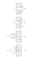
- FIGS. 1 and 2 are diagrams for explaining a conventional general drilling process.
- the tool T is first fast-forwarded to the reference point (hereinafter referred to as the R point) which is the drilling start position.
- the R point which is the drilling start position.
- the tool is moved at the feed rate of the cutting feed until the tool T reaches the hole bottom from the R point. That is, the feed rate is the same from the biting portion at the moment when the tool T comes into contact with the work W (see (b) in FIG. 1) to the drilling operation after the contact (see (c) in FIG. 1).
- the feed rate is the same even at the through portion (see (d) in FIG. 1) at the moment when the hole is opened.
- the bite speed (feed speed at the bite portion; the same applies hereinafter) and the penetration speed (feed speed at the penetration portion; the same applies hereinafter) are set based on the set value or the machining program command.
- the appropriate bite speed and penetration speed vary depending on the work surface shape such as unevenness and inclination of the work surface and the type of tool. Therefore, it is difficult to set an appropriate bite speed and penetration speed for all drilling operations.
- One aspect of the present disclosure is a speed adjusting device that adjusts the speed of the drive shaft of a machine tool that processes a work using a tool, and is determined according to the tool used, the work shape at the speed adjusting location, and the path information.
- the work shape at the speed adjustment point and the speed adjustment point is specified based on the storage unit that stores the calculation method of the adjustment speed of the drive shaft at the speed adjustment point, the shape data of the work, and the path information.
- the speed adjustment location is based on the tool data, the work shape at the speed adjustment location specified by the speed adjustment location identification portion, the path information, and the storage information stored in the storage unit.
- It is a speed adjustment device provided with an adjustment speed calculation unit for determining a method for calculating the adjustment speed of the drive shaft in the above and calculating the adjustment speed at the speed adjustment point based on the determined calculation method.
- the speed adjusting device 1 adjusts the speed of the drive shaft of the machine tool that processes the work W by using the tool T at a place where the speed should be adjusted (hereinafter referred to as a speed adjusting place). It is something to do. More specifically, for example, in the speed adjusting device 1 according to the present embodiment, the speed of the drive shaft of the machine tool for drilling the work W by using a drill as the tool T is adjusted to the biting portion and the penetrating portion as the speed adjusting portion. It is to be adjusted in.
- the speed adjusting device 1 has a hardware configuration such as a CPU, ROM, RAM, non-volatile memory, bus, axis control circuit, servo amplifier, and interface (not shown). Further, a servomotor 20, an input / output device, and the like are connected to the speed adjusting device 1 according to the present embodiment.
- FIG. 3 is a block diagram showing a functional configuration of the speed adjusting device 1 according to the present embodiment.
- the speed adjusting device 1 according to the present embodiment outputs a movement command based on the machining program, and drives and controls the servomotor 20 in each drive shaft of the machine tool based on the movement command. It is provided in the numerical control device for processing the work W.
- the speed adjustment device 1 includes a storage unit 11, a speed adjustment location specifying unit 12, an adjustment speed calculation unit 13, a speed adjustment unit 14, and distribution of an interpolation movement command. It includes a processing unit 15, an acceleration / deceleration start position calculation unit 16, a movement command output unit 17, an acceleration / deceleration processing unit 18, and a servo control unit 19.
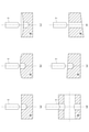
- FIG. 4 is a diagram showing drilling when the work surface has irregularities or inclinations.
- 4A shows a case where the bite portion has a plurality of irregularities
- FIG. 4B shows a case where the bite portion has a curved convex shape
- FIG. 4C shows a case where the bite portion has a curved concave shape.
- FIG. 4 (d) is a circular tubular work W, and when the portion where the processing path and the hollow portion intersect (the penetrating portion and the biting portion inside the work W) is curved, the biting portion is shown in FIG. 4 (e).
- FIG. 4 (f) shows a case where the penetrating portion is an inclined surface.
- the speed adjusting device 1 adjusts the biting speed and the penetrating speed according to the shape of the biting portion and the penetrating portion as the speed adjusting portion, in addition to the tool used and the route information. That is, the speed adjusting device 1 according to the present embodiment adjusts the biting speed and the penetrating speed based on the surface shape such as unevenness and inclination in the biting portion and the penetrating portion, whereby the biting portion and the penetrating portion in the biting portion and the penetrating portion. It is possible to reliably suppress the occurrence of burrs and tool defects.
- the storage unit 11 stores a method of calculating the adjustment speed of the drive shaft at the speed adjustment point, which is determined according to the tool used, the work shape at the speed adjustment point, and the path information.
- the route information can be acquired from the machining program.
- the storage unit 11 creates a table in which the tool used, the work shape and the path information at the speed adjustment point are associated with the calculation method of the drive shaft adjustment speed at the speed adjustment point, and stores the created table in advance. May be good.
- the inclined surface angle is inclined.
- the adjustment speed of the drive shaft at the speed adjustment point is set to 1/3 of the normal speed
- the inclination angle of the inclined surface is 2 degrees or less
- the adjustment speed of the drive shaft at the speed adjustment point is 1/3 of the normal speed.
- the normal speed is a machining speed that can be obtained from the machining program, and is a reference speed when calculating the adjustment speed.
- the speed adjustment point specifying unit 12 specifies the work shape at the speed adjustment point and the speed adjustment point based on the shape data and the route information of the work W.
- the shape data of the work W is, for example, CAD data of the work W, and it is also possible to use an captured image of the work W instead of the CAD data.
- the route information can be acquired from the machining program.
- the speed adjusting points are the biting portion and the penetrating portion as described above. That is, in the case of drilling, the speed adjusting portion specifying portion 12 specifies the work shape in the biting portion and the penetrating portion.
- the speed adjustment location specifying portion 12 determines the machining path of the drilling cycle in the machining program and the shape of the surface including the intersection with the machining path if the shape data of the work W is surface information. Specified as the shape of. In this way, the speed adjustment portion specifying portion 12 obtains, for example, the inclination angle (for example, 3 degrees) of the surface specified as the shape of the speed adjustment portion.
- the R point as a reference point is specified in the machining program, the R point may be used instead of the machining path of the drilling cycle. That is, the shape of the surface including the intersection with the line drawn from the R point in the traveling direction of the tool T may be specified as the shape of the speed adjusting portion.
- the adjustment speed calculation unit 13 determines the drive shaft at the speed adjustment location based on the tool data, the work shape at the speed adjustment location specified by the speed adjustment location identification unit 12, the path information, and the storage information stored in the storage unit 11. Determine how to calculate the adjustment speed. As described above, in the present embodiment, the route information can be acquired from the machining program.
- the adjustment speed calculation unit 13 calculates the adjustment speed at the speed adjustment location specified by the speed adjustment location identification unit 12 based on the calculation method of the adjustment speed of the drive shaft at the determined speed adjustment location. If it is an example of the above-mentioned calculation method, that is, "when the inclination angle of the inclined surface is 2 degrees or more, the adjustment speed of the drive shaft at the speed adjustment point is set to 1/3 of the normal speed", it is specified in the machining program. The adjustment speed is the speed calculated by multiplying the machining speed by 1/3. The adjustment speed at the speed adjustment point calculated in this way is output to the speed adjustment unit 14 described later.
- the speed adjustment unit 14 uses the adjustment speed at the speed adjustment location specified by the speed adjustment location identification unit 12 as the adjustment speed calculated by the adjustment speed calculation unit 13. As a result, the speed at the speed adjustment point is automatically adjusted.
- the distribution processing unit 15 of the interpolation movement command generates an interpolation movement command based on the speed-adjusted machining program command by the speed adjustment unit 14, and generates a distribution command for distributing the generated interpolation movement command to each drive axis. ..
- the generated distribution command is output to the movement command output unit 17 described later.
- the acceleration / deceleration start position calculation unit 16 calculates the acceleration / deceleration start position based on the position of the speed adjustment point specified by the speed adjustment point identification unit 12 and the speed and acceleration specified by the machining program command. Further, the acceleration / deceleration start position calculation unit 16 outputs the calculated acceleration / deceleration start position to the distribution processing unit 15 of the above-mentioned interpolation movement command. As a result, the moving speed becomes a predetermined adjustment speed before reaching the speed adjustment point.
- the movement command output unit 17 generates a movement command for each drive axis based on the distribution command generated and output by the distribution processing unit 15 of the interpolation movement command.
- the generated movement command is output to the acceleration / deceleration processing unit 18 described later.
- the acceleration / deceleration processing unit 18 executes the acceleration / deceleration processing after interpolation based on the movement command generated and output by the movement command output unit 17.
- the servo control unit 19 controls the servomotors 20 provided on each drive shaft of the machine tool based on the movement command processed by the acceleration / deceleration processing unit 18.
- the present embodiment includes a storage unit 11 that stores a method of calculating the adjustment speed of the drive shaft at the speed adjustment point, which is determined according to the tool used, the work shape at the speed adjustment point, and the path information. Further, the speed adjusting portion specifying unit 12 for specifying the speed adjusting portion and the work shape at the speed adjusting portion is provided based on the shape data and the route information of the work W. Further, a method of calculating the adjustment speed of the drive shaft at the speed adjustment location based on the tool data, the work shape at the speed adjustment location specified by the speed adjustment location specifying unit 12, the path information, and the storage information stored in the storage unit 11.
- the adjustment speed calculation unit 13 for calculating the adjustment speed at the speed adjustment point based on the determined calculation method is provided. Further, the speed adjusting unit 14 is provided with the adjustment speed at the speed adjusting portion specified by the speed adjusting portion specifying unit 12 as the adjusting speed calculated by the adjusting speed calculation unit 13.
- the speed adjusting portion specifying unit 12 specifies the work shape at the speed adjusting portion and the speed adjusting portion based on the shape data and the route information of the work W.
- the adjustment speed calculation unit 13 determines a method for calculating the adjustment speed of the drive shaft at the speed adjustment location based on the tool data, the work shape at the specified speed adjustment location, the path information, and the storage information of the storage unit 11. .. Further, the adjustment speed calculation unit 13 calculates the adjustment speed at the speed adjustment point based on the determined calculation method.
- the speed adjustment unit 14 adjusts the adjustment speed at the specified speed adjustment point to the calculated adjustment speed.
- the speed adjusting device 1 According to the speed adjusting device 1 according to the present embodiment that operates as described above, by referring to the stored information stored in advance in the storage unit 11 based on the tool used, the work shape at the speed adjusting portion, and the route information. , The adjustment speed of the drive shaft at the speed adjustment point can be automatically adjusted. Specifically, in the case of drilling, the feed rate at the bite portion and the penetration portion can be automatically adjusted. Therefore, according to the present embodiment, an appropriate adjustment speed can be automatically determined at the speed adjustment location, and burrs and tool defects can be reliably suppressed without unnecessarily extending the cycle time.
- drilling using a drill has been described as an example, but the present invention is not limited to this.
- the present disclosure may be applied to turning, milling, and the like.
- the speed adjusting device 1 is provided in the numerical control device, the adjusting speed is determined for the machining program, the speed is adjusted, and the overriding is performed, but the present invention is not limited to this.
- the adjustment speed may be determined at the time of generating a machining program such as interactive program creation software or CAM, and may be reflected in the machining program. That is, the speed adjusting device 1 (however, excluding the speed adjusting unit 14) may be provided in the CAM, the program generation device, or another external device instead of the numerical control device.
- a presentation unit may be provided in which the adjustment speed calculated by the adjustment speed calculation unit 13 is presented as a recommended adjustment speed. Thereby, for example, after the user confirms the recommended adjustment speed presented by the presenting unit, the speed adjustment can be executed according to the input by the user.
- Speed adjustment device 11 Storage unit 12 Speed adjustment location identification unit 13 Adjustment speed calculation unit 14 Speed adjustment unit 15 Interference movement command distribution processing unit 16 Acceleration / deceleration start position calculation unit 17 Movement command output unit 18 Acceleration / deceleration processing unit 19 Servo control Part 20 Servo motor T tool W work
Landscapes
- Engineering & Computer Science (AREA)
- Mechanical Engineering (AREA)
- Human Computer Interaction (AREA)
- Manufacturing & Machinery (AREA)
- Physics & Mathematics (AREA)
- General Physics & Mathematics (AREA)
- Automation & Control Theory (AREA)
- Numerical Control (AREA)
Abstract
Description
11 記憶部
12 速度調整箇所特定部
13 調整速度算出部
14 速度調整部
15 補間移動指令の分配処理部
16 加減速開始位置算出部
17 移動指令出力部
18 加減速処理部
19 サーボ制御部
20 サーボモータ
T 工具
W ワーク
Claims (3)
- 工具を使用してワークを加工する工作機械の駆動軸の速度を調整する速度調整装置であって、
使用工具、速度調整箇所におけるワーク形状及び経路情報に応じて決定される、前記速度調整箇所における前記駆動軸の調整速度の算出方法を記憶する記憶部と、
前記ワークの形状データ及び前記経路情報に基づいて、前記速度調整箇所及び前記速度調整箇所におけるワーク形状を特定する速度調整箇所特定部と、
工具データ、前記速度調整箇所特定部で特定された前記速度調整箇所におけるワーク形状、前記経路情報及び前記記憶部に記憶された記憶情報に基づいて、前記速度調整箇所における前記駆動軸の調整速度の算出方法を決定し、決定された前記算出方法に基づいて前記速度調整箇所における調整速度を算出する調整速度算出部と、を備える、速度調整装置。 - 前記速度調整箇所特定部で特定された前記速度調整箇所における調整速度を、前記調整速度算出部で算出された調整速度とする速度調整部をさらに備える、請求項1に記載の速度調整装置。
- 前記調整速度算出部で算出された調整速度を推奨調整速度として提示する提示部をさらに備える、請求項1又は2に記載の速度調整装置。
Priority Applications (4)
| Application Number | Priority Date | Filing Date | Title |
|---|---|---|---|
| CN202180052500.8A CN115885227A (zh) | 2020-08-25 | 2021-08-20 | 速度调整装置 |
| JP2022544537A JPWO2022044989A1 (ja) | 2020-08-25 | 2021-08-20 | |
| DE112021004475.3T DE112021004475T5 (de) | 2020-08-25 | 2021-08-20 | Geschwindigkeitsjustiervorrichtung |
| US18/042,967 US12474693B2 (en) | 2020-08-25 | 2021-08-20 | Speed adjustment device |
Applications Claiming Priority (2)
| Application Number | Priority Date | Filing Date | Title |
|---|---|---|---|
| JP2020141851 | 2020-08-25 | ||
| JP2020-141851 | 2020-08-25 |
Publications (1)
| Publication Number | Publication Date |
|---|---|
| WO2022044989A1 true WO2022044989A1 (ja) | 2022-03-03 |
Family
ID=80355223
Family Applications (1)
| Application Number | Title | Priority Date | Filing Date |
|---|---|---|---|
| PCT/JP2021/030547 Ceased WO2022044989A1 (ja) | 2020-08-25 | 2021-08-20 | 速度調整装置 |
Country Status (5)
| Country | Link |
|---|---|
| US (1) | US12474693B2 (ja) |
| JP (1) | JPWO2022044989A1 (ja) |
| CN (1) | CN115885227A (ja) |
| DE (1) | DE112021004475T5 (ja) |
| WO (1) | WO2022044989A1 (ja) |
Citations (4)
| Publication number | Priority date | Publication date | Assignee | Title |
|---|---|---|---|---|
| JP2003256010A (ja) * | 2002-03-06 | 2003-09-10 | Mazda Motor Corp | 工作機械の制御方法及びその制御装置、並びに、その制御をコンピュータに実行させるプログラム及びそれを記録したコンピュータ読み取り可能な記録媒体 |
| JP2003308104A (ja) * | 2002-04-16 | 2003-10-31 | Yamazaki Mazak Corp | 3次元線状加工装置 |
| JP2003345408A (ja) * | 2002-05-22 | 2003-12-05 | Amada Co Ltd | 切削加工方法及び装置並びに鋸盤 |
| JP2018060500A (ja) * | 2016-09-30 | 2018-04-12 | 株式会社小松製作所 | 工作システム、切削加工品の製造方法、加工プログラム修正装置、修正加工プログラムの作成方法、及び工作機械制御装置 |
Family Cites Families (6)
| Publication number | Priority date | Publication date | Assignee | Title |
|---|---|---|---|---|
| JP3189829B2 (ja) * | 1999-05-26 | 2001-07-16 | 三菱電機株式会社 | 数値制御装置 |
| CN203418368U (zh) | 2013-06-27 | 2014-02-05 | 苏州边枫电子科技有限公司 | 基于基材压力的钻头进给速度调节装置 |
| JP6219897B2 (ja) | 2015-09-28 | 2017-10-25 | ファナック株式会社 | 最適な加減速を生成する工作機械 |
| CN205324792U (zh) | 2016-01-08 | 2016-06-22 | 哈尔滨理工大学 | 一种深孔加工装置 |
| JP6966412B2 (ja) * | 2018-11-15 | 2021-11-17 | ファナック株式会社 | 数値制御装置 |
| JP2020095317A (ja) * | 2018-12-10 | 2020-06-18 | ファナック株式会社 | 数値制御装置 |
-
2021
- 2021-08-20 JP JP2022544537A patent/JPWO2022044989A1/ja active Pending
- 2021-08-20 US US18/042,967 patent/US12474693B2/en active Active
- 2021-08-20 WO PCT/JP2021/030547 patent/WO2022044989A1/ja not_active Ceased
- 2021-08-20 CN CN202180052500.8A patent/CN115885227A/zh active Pending
- 2021-08-20 DE DE112021004475.3T patent/DE112021004475T5/de active Pending
Patent Citations (4)
| Publication number | Priority date | Publication date | Assignee | Title |
|---|---|---|---|---|
| JP2003256010A (ja) * | 2002-03-06 | 2003-09-10 | Mazda Motor Corp | 工作機械の制御方法及びその制御装置、並びに、その制御をコンピュータに実行させるプログラム及びそれを記録したコンピュータ読み取り可能な記録媒体 |
| JP2003308104A (ja) * | 2002-04-16 | 2003-10-31 | Yamazaki Mazak Corp | 3次元線状加工装置 |
| JP2003345408A (ja) * | 2002-05-22 | 2003-12-05 | Amada Co Ltd | 切削加工方法及び装置並びに鋸盤 |
| JP2018060500A (ja) * | 2016-09-30 | 2018-04-12 | 株式会社小松製作所 | 工作システム、切削加工品の製造方法、加工プログラム修正装置、修正加工プログラムの作成方法、及び工作機械制御装置 |
Also Published As
| Publication number | Publication date |
|---|---|
| US20230297078A1 (en) | 2023-09-21 |
| JPWO2022044989A1 (ja) | 2022-03-03 |
| DE112021004475T5 (de) | 2023-08-10 |
| CN115885227A (zh) | 2023-03-31 |
| US12474693B2 (en) | 2025-11-18 |
Similar Documents
| Publication | Publication Date | Title |
|---|---|---|
| JP6487397B2 (ja) | 工作機械の制御装置、制御方法及びコンピュータプログラム | |
| JP6140130B2 (ja) | 工具及び被加工物を保護する数値制御装置 | |
| CN109725602B (zh) | 数值控制装置及方法、cnc机床、计算机可读信息记录介质 | |
| JP2017207806A (ja) | 揺動切削を行う工作機械のサーボ制御装置、制御方法及びコンピュータプログラム | |
| JP6646027B2 (ja) | ポストプロセッサ装置、加工プログラム生成方法、cnc加工システム及び加工プログラム生成用プログラム | |
| US20200290207A1 (en) | Real-time identification of burr size and location for robotic deburring process | |
| JP2017204072A (ja) | 加工プログラム処理装置およびこれを備えた多軸加工機 | |
| JP6865058B2 (ja) | 工作システム、切削加工品の製造方法、加工プログラム修正装置、修正加工プログラムの作成方法、及び工作機械制御装置 | |
| WO2008053601A1 (en) | Working control device, and its program | |
| JP7645761B2 (ja) | ワークの旋削加工方法及び工作機械、加工プログラム | |
| JP2013175129A (ja) | 数値制御装置 | |
| JP2009136956A (ja) | 旋削加工方法及び旋削条件及び切削経路生成方法 | |
| JP5032081B2 (ja) | 工作機械における加工制御方法及び加工情報作成方法 | |
| WO2018198274A1 (ja) | 加工制御装置及び工作機械、並びに加工制御方法 | |
| WO2022044989A1 (ja) | 速度調整装置 | |
| JP6249904B2 (ja) | 工作機械のワーク加工制御装置,該制御装置を用いたワーク加工方法,及びワーク加工プログラム | |
| JP6972404B1 (ja) | プログラム、clデータ編集装置及び工作機械 | |
| CN106814689B (zh) | 数值控制装置 | |
| JP5705355B1 (ja) | 壁部の加工方法および工具経路生成装置 | |
| JP6062971B2 (ja) | スカイビング加工指令に基づいて工作機械を制御する数値制御装置 | |
| JP6919427B2 (ja) | 工作機械、工作機械の制御方法、及び、工作機械の制御プログラム | |
| JP6959477B1 (ja) | レーザ加工機の制御装置 | |
| JP2020194511A (ja) | 数値制御装置及び工作機械 | |
| JP2017177272A (ja) | 数値制御装置 | |
| JP7448658B2 (ja) | 工作機械の制御装置と制御方法及びスレーブ軸制御装置 |
Legal Events
| Date | Code | Title | Description |
|---|---|---|---|
| 121 | Ep: the epo has been informed by wipo that ep was designated in this application |
Ref document number: 21861416 Country of ref document: EP Kind code of ref document: A1 |
|
| ENP | Entry into the national phase |
Ref document number: 2022544537 Country of ref document: JP Kind code of ref document: A |
|
| 122 | Ep: pct application non-entry in european phase |
Ref document number: 21861416 Country of ref document: EP Kind code of ref document: A1 |
|
| WWG | Wipo information: grant in national office |
Ref document number: 18042967 Country of ref document: US |