WO2022044547A1 - 高周波信号再放射装置、高周波信号受信装置、および、無線システム - Google Patents
高周波信号再放射装置、高周波信号受信装置、および、無線システム Download PDFInfo
- Publication number
- WO2022044547A1 WO2022044547A1 PCT/JP2021/025182 JP2021025182W WO2022044547A1 WO 2022044547 A1 WO2022044547 A1 WO 2022044547A1 JP 2021025182 W JP2021025182 W JP 2021025182W WO 2022044547 A1 WO2022044547 A1 WO 2022044547A1
- Authority
- WO
- WIPO (PCT)
- Prior art keywords
- frequency signal
- packet
- signal
- unit
- delay
- Prior art date
- Legal status (The legal status is an assumption and is not a legal conclusion. Google has not performed a legal analysis and makes no representation as to the accuracy of the status listed.)
- Ceased
Links
Images











Classifications
-
- H—ELECTRICITY
- H04—ELECTRIC COMMUNICATION TECHNIQUE
- H04B—TRANSMISSION
- H04B1/00—Details of transmission systems, not covered by a single one of groups H04B3/00 - H04B13/00; Details of transmission systems not characterised by the medium used for transmission
- H04B1/005—Details of transmission systems, not covered by a single one of groups H04B3/00 - H04B13/00; Details of transmission systems not characterised by the medium used for transmission adapting radio receivers, transmitters andtransceivers for operation on two or more bands, i.e. frequency ranges
- H04B1/0067—Details of transmission systems, not covered by a single one of groups H04B3/00 - H04B13/00; Details of transmission systems not characterised by the medium used for transmission adapting radio receivers, transmitters andtransceivers for operation on two or more bands, i.e. frequency ranges with one or more circuit blocks in common for different bands
- H04B1/0071—Details of transmission systems, not covered by a single one of groups H04B3/00 - H04B13/00; Details of transmission systems not characterised by the medium used for transmission adapting radio receivers, transmitters andtransceivers for operation on two or more bands, i.e. frequency ranges with one or more circuit blocks in common for different bands using a common intermediate frequency for more than one band
-
- G—PHYSICS
- G01—MEASURING; TESTING
- G01S—RADIO DIRECTION-FINDING; RADIO NAVIGATION; DETERMINING DISTANCE OR VELOCITY BY USE OF RADIO WAVES; LOCATING OR PRESENCE-DETECTING BY USE OF THE REFLECTION OR RERADIATION OF RADIO WAVES; ANALOGOUS ARRANGEMENTS USING OTHER WAVES
- G01S19/00—Satellite radio beacon positioning systems; Determining position, velocity or attitude using signals transmitted by such systems
- G01S19/01—Satellite radio beacon positioning systems transmitting time-stamped messages, e.g. GPS [Global Positioning System], GLONASS [Global Orbiting Navigation Satellite System] or GALILEO
- G01S19/03—Cooperating elements; Interaction or communication between different cooperating elements or between cooperating elements and receivers
- G01S19/10—Cooperating elements; Interaction or communication between different cooperating elements or between cooperating elements and receivers providing dedicated supplementary positioning signals
- G01S19/11—Cooperating elements; Interaction or communication between different cooperating elements or between cooperating elements and receivers providing dedicated supplementary positioning signals wherein the cooperating elements are pseudolites or satellite radio beacon positioning system signal repeaters
-
- H—ELECTRICITY
- H04—ELECTRIC COMMUNICATION TECHNIQUE
- H04B—TRANSMISSION
- H04B7/00—Radio transmission systems, i.e. using radiation field
- H04B7/14—Relay systems
- H04B7/15—Active relay systems
- H04B7/155—Ground-based stations
-
- H—ELECTRICITY
- H04—ELECTRIC COMMUNICATION TECHNIQUE
- H04L—TRANSMISSION OF DIGITAL INFORMATION, e.g. TELEGRAPHIC COMMUNICATION
- H04L7/00—Arrangements for synchronising receiver with transmitter
- H04L7/04—Speed or phase control by synchronisation signals
- H04L7/06—Speed or phase control by synchronisation signals the synchronisation signals differing from the information signals in amplitude, polarity or frequency or length
Definitions
- This technology is related to wireless systems. More specifically, the present invention relates to a high-frequency signal re-radiating device for positioning or time synchronization, a high-frequency signal receiving device, and a wireless system.
- the GNSS receiver that receives the GNSS (Global Navigation Satellite System) signal can obtain not only the position information but also the accurate time synchronized with the GNSS high-precision clock, and 1 micron using multiple GNSS receivers. Time can be synchronized in less than a second. Since this GNSS receiver cannot often receive the GNSS signal from the satellite indoors, it cannot be used as it is. Therefore, a system has been proposed in which a signal from a satellite is received by a server and time information and spatial information are distributed to a terminal device (see, for example, Patent Document 1).
- time information and spatial information are used in an indoor terminal.
- this conventional technique is supposed to be used in a terminal connected to a local area network, and cannot be used in a normal GNSS receiver. Further, when the terminal assumed in the prior art is moved outdoors, the time information and the spatial information cannot be used.
- This technology was created in view of this situation, and aims to make GNSS receivers used outdoors available indoors as well.
- the present technology has been made to solve the above-mentioned problems, and the first aspect thereof is synchronization with a packet receiving unit for receiving a packet generated based on a first high-frequency signal and the above-mentioned packet.
- a packet receiving unit for receiving a packet generated based on a first high-frequency signal and the above-mentioned packet.
- It is a high frequency signal re-radiating device including a packet interpretation unit that performs processing to generate an intermediate frequency signal, and a high frequency signal transmission unit that converts the intermediate frequency signal into a second high frequency signal and transmits the intermediate frequency signal. This has the effect of re-radiating the second high frequency signal obtained from the received packet.
- the packet interpreting unit may detect the missing packet and interpolate dummy data into the missing portion. This has the effect of keeping the packets in sync so that they do not become discontinuous signals.
- the packet interpretation unit reads the packet from the buffer memory for holding the packet and the remaining amount of the buffer memory, and is common with the high frequency signal transmission unit.
- a rate adjusting unit that outputs the intermediate frequency signal according to the clock frequency of the above may be provided. This has the effect of adjusting the packet rate to keep it in sync.
- the delay measuring unit for measuring the delay time with the other device that generated the packet is further provided, and the packet interpreting unit further comprises the intermediate frequency signal based on the delay time. May be generated. This has the effect of improving the accuracy of time synchronization.
- the delay measuring unit may measure the delay time by transmitting and receiving the delay measurement packet to and from the other device. This has the effect of improving the accuracy of time synchronization using the delay measurement packet.
- a beacon receiving unit for receiving a time-synchronized beacon signal is further provided, and the packet interpreting unit generates the intermediate frequency signal based on the reception timing of the beacon signal. May be good. This has the effect of improving the accuracy of time synchronization using the beacon signal.
- the high frequency signal transmission unit may transmit an identification signal for identifying the re-radiated signal in addition to the second high frequency signal. This has the effect of identifying the re-radiated signal on the receiving side of the second high frequency signal.
- the packet may include a GNSS signal, or may include an indoor positioning signal carrying time information synchronized with a synchronization pulse.
- the second aspect of the present technology is a high-frequency signal receiving unit that receives a high-frequency signal and generates an intermediate frequency signal, a packet generating unit that generates a packet based on the high-frequency signal, and the generated packet. It is a high frequency signal receiving device including a packet output unit for outputting to a communication path. This has the effect of packetizing the received high-frequency signal and outputting it to the communication path.
- the packet generation unit may receive the GNSS signal as the high frequency signal and generate the packet including the GNSS signal.
- the packet generation unit receives the GNSS signal as the high frequency signal, acquires the synchronization pulse from the GNSS signal, and carries the time information synchronized with the synchronization pulse.
- the above packet including the indoor positioning signal may be generated.
- a beacon transmission unit that transmits a beacon at a timing synchronized with the synchronization pulse may be further provided.
- a delay measuring unit for measuring a delay time with another device that receives the packet is further provided, and the packet generating unit generates the packet based on the delay time. You may try to do it. This has the effect of improving the accuracy of time synchronization.
- the delay measuring unit may measure the delay time by transmitting and receiving the delay measurement packet to and from the other device. This has the effect of improving the accuracy of time synchronization using the delay measurement packet.
- the packet generation unit may generate the packet by adding an identification signal for identifying the signal as being re-radiated. This has the effect of identifying the re-radiated signal on the receiving side of the re-radiated high frequency signal.
- the third aspect of the present technology is a high frequency signal receiving unit that receives a first high frequency signal and generates a first intermediate frequency signal, and a packet generation that generates a packet based on the first high frequency signal.
- a high-frequency signal receiving device including a unit and a packet output unit that outputs the generated packet to the communication path, a packet receiving unit that receives the packet via the communication path, and the packet are synchronized.
- a high-frequency signal re-radiating device including a packet interpreting unit that generates a second intermediate frequency signal, a high-frequency signal transmitting unit that converts the second intermediate frequency signal into a second high-frequency signal and transmits the second intermediate frequency signal, and the second intermediate frequency signal.
- the first high-frequency signal received by the high-frequency signal receiver is packetized and transmitted, the second high-frequency signal is re-radiated by the high-frequency signal re-radiating device, and positioning or time synchronization is performed by the wireless receiver. Brings action.
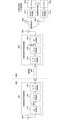
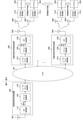
- FIG. 1 is a diagram showing an outline of an example of a wireless system according to an embodiment of the present technology.
- This wireless system is a system that receives GNSS signals from the GNSS satellite 10, and includes a high-frequency signal receiving device 100, a high-frequency signal re-radiating device 300, and a GNSS receiver 510.
- the high frequency signal receiving device 100 is a device that receives a GNSS signal from the GNSS satellite 10 as a high frequency signal, generates a predetermined packet, and outputs the packet to the communication path 200.
- the high-frequency signal re-radiating device 300 is a device that receives a packet output to the communication path 200, interprets the packet, and re-radiates it as a high-frequency signal. It is assumed that the high frequency signal receiving device 100 is arranged outdoors and the high frequency signal reradiating device 300 is arranged indoors.
- the high-frequency signal receiver 100 receives the GNSS signal from the GNSS satellite 10 outdoors, transmits the packet through the communication path 200, and the high-frequency signal re-radiating device 300 uses the packet as a high-frequency signal for the indoor GNSS receiver 510. Re-radiate towards.
- the GNSS receiver 510 is a device that receives a GNSS signal from the GNSS satellite 10 outdoors and performs positioning or time synchronization. However, in this embodiment, assuming that the GNSS receiver 510 is also used indoors, the high frequency signal re-radiating device 300 reradiates the high frequency signal toward the GNSS receiver 510.
- the GNSS receiver 510 is an example of the wireless receiver described in the claims.
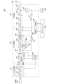
- FIG. 2 is a diagram showing a configuration example of a wireless system according to the first embodiment of the present technology.
- the high frequency signal may be referred to as "RF” (Radio Frequency) or “RF signal”
- the intermediate frequency signal may be referred to as "IF” (Intermediate Frequency) or "IF signal”.
- the high frequency signal receiving device 100 includes an RF receiving unit 110, a packet conversion unit 120, and an Ethernet control unit 130.
- the RF receiving unit 110 converts a GNSS signal, which is a high frequency signal received via the antenna 109, into a digital IF signal and outputs the signal.
- the packet conversion unit 120 converts the IF signal into a packet for sending to Ethernet.
- the Ethernet control unit 130 sends the packet converted by the packet conversion unit 120 to the communication path 200.
- the Ethernet control unit 130 is an example of the packet output unit described in the claims.
- the communication path 200 may be either wired or wireless.
- the wired communication path 200 for example, an Ethernet cable (for example, 100base-T), PoE (Power over Ethernet), a power line, or the like is assumed.
- the wireless communication path 200 for example, WiFi (registered trademark) or the like is assumed.
- UDP User Datagram Protocol
- TCP Transmission Control Protocol
- packet transmission in this communication path 200 is mainly in one direction from the high frequency signal receiving device 100 to the high frequency signal reradiating device 300, but in order to negotiate within the network at the initial stage, bidirectional communication is performed as a whole. Will do.
- the high frequency signal re-radiating device 300 includes an Ethernet control unit 310, a packet interpretation unit 320, and an RF transmission unit 330.
- the Ethernet control unit 310 receives the packet output to the communication path 200.
- the Ethernet control unit 310 is an example of the packet receiving unit described in the claims.
- the packet interpretation unit 320 interprets the received packet and returns it to the IF signal. When a packet is missing, the packet interpreting unit 320 interpolates, for example, an all-zero packet, as will be described later.
- the RF transmission unit 330 converts the digital IF signal output from the packet interpretation unit 320 into an RF signal, and transmits the GNSS signal via the antenna 399.
- the outdoor antenna 109 receives, for example, a GNSS signal of 1575.42 MHz.
- the antenna 109 is preferably located on a rooftop or other place having a good reception environment, but may be, for example, near an indoor window as long as it can receive GNSS signals.
- the antenna 399 for re-radiation can use the same frequency as the GNSS signal from the GNSS satellite 10 (for example, 1575.42 MHz). In this case, since the signal used for re-radiating the GNSS signal is a weak radio wave, it does not affect other devices.
- a system 520 such as a terminal is connected to the GNSS receiver 510.
- the re-radiation described above allows the GNSS receiver 510 to supply accurate time and location information to the system 520.
- the delay from the antenna 109 to the antenna 399 is common to all the systems 520.
- the difference in distance between the antenna 399 and the antenna 509 of the GNSS receiver 510 is considered to be about 20 meters at the maximum, so that the delay time is 100 nanoseconds or less. Therefore, even if these delays are taken into consideration, it is possible to perform highly accurate synchronous operation between the systems 520.
- FIG. 3 is a diagram showing a configuration example of the high frequency signal receiving device 100 according to the first embodiment of the present technology.
- the high frequency signal receiving device 100 includes an RF receiving unit 110, a packet conversion unit 120, and an Ethernet control unit 130. Further, the high frequency signal receiving device 100 includes a temperature-compensated crystal oscillator (TCXO: Temperature-Compensated crystal Oscillator) 140 and a host computer 150. The temperature-compensated crystal oscillator 140 outputs a signal having an oscillation frequency such as 16.368 MHz or 26 MHz.
- TXO Temperature-Compensated crystal Oscillator
- the RF receiving unit 110 includes a low noise amplifier 111, a mixer 112, a low-pass filter 113, a variable gain amplifier 114, an AD converter 115, a phase-locked loop 116, a buffer 117, a frequency divider 118, and a control unit 119.
- the low noise amplifier (LNA: Low Noise Amplifier) 111 is an amplifier that amplifies the high frequency signal received by the antenna 109.
- the phase-locked loop (PLL) 116 is a circuit that generates a phase-locked signal based on the output of the temperature-compensated crystal oscillator 140.
- the mixer 112 is a circuit that down-converts to a baseband signal by mixing the high frequency signal amplified by the low noise amplifier 111 and the signal from the phase-locked loop 116.
- the low-pass filter (LPF) 113 is a filter that limits the band by removing the high frequency component of the baseband signal output from the mixer 112.
- the variable gain amplifier (VGA: Variable-Gain Amplifier) 114 is an amplifier that amplifies the output of the low-pass filter 113 by a variable gain.
- the buffer 117 is a circuit that amplifies the output of the temperature-compensated crystal oscillator 140 and distributes it as a clock signal.
- the frequency divider 118 is a circuit that divides the clock signal distributed from the buffer 117 into 1 / N.
- the AD converter (ADC: Analog-to-Digital Converter) 115 is a circuit that converts an analog signal amplified by the variable gain amplifier 114 into a digital signal.
- the AD converter 115 operates in synchronization with the clock signal from the frequency divider 118, and outputs the converted digital signal as an intermediate frequency signal IF_in.
- IF_in an intermediate frequency signal
- an IQ-modulated signal is assumed.
- each signal of I channel (In-phase: in-phase component) and Q channel (Quadrature: orthogonal component) is used as a baseband signal.
- a total of 2 bits of 2.046 Mps (sample per second) signal of 1 bit of I channel and 1 bit of Q channel is assumed.
- the control unit 119 controls the entire RF receiving unit 110.
- the packet conversion unit 120 includes a serial / parallel converter 121, a FIFA 122, a packet generation unit 123, a frequency divider 124, a clock generation unit 128, and a control unit 129.
- the serial / parallel converter 121 is a circuit that converts an intermediate frequency signal IF_in input from the RF receiving unit 110 from a serial signal to a parallel signal.
- the serial / parallel converter 121 outputs a write request to the FIFA 122 together with the data converted into a parallel signal.
- As the data output from the serial / parallel converter 121 for example, 8-bit width data and a signal of 0.5115 Mbps are assumed.
- the FIFO 122 is a FIFO (First-In First-Out) buffer that holds data of an intermediate frequency signal converted into a parallel signal by the serial / parallel converter 121.
- the frequency divider 124 is a circuit that divides the clock signal distributed from the buffer 117 into 1 / N.
- the write operation of the serial / parallel converter 121 and the FIFA 122 operates in synchronization with the clock signal from the frequency divider 124.
- the packet generation unit 123 outputs a read request to the FIFA 122, reads the data held in the FIFA 122, and generates a packet.
- the packet output from the packet generation unit 123 has, for example, a capacity of 170 bytes per packet.
- the clock generation unit 128 generates a clock signal to be used after the read operation from the FIFA 122. That is, the read operation of the packet generation unit 123 and the FIFA 122 operates in synchronization with the clock signal from the clock generation unit 128.
- the control unit 129 controls the entire packet conversion unit 120.
- the Ethernet control unit 130 controls the MAC (Medium Access Control) layer 131 and the physical layer (PHY layer) 132.
- the Ethernet control unit 130 outputs a packet to the communication path 200 in synchronization with the clock signal from the clock generation unit 128.
- the host computer 150 controls the operation of the high-frequency signal receiving device 100.
- the RF receiving unit 110 is connected to the control unit 119, and the packet conversion unit 120 is connected to the control unit 129 to perform various settings and monitors. Perform operations, etc.
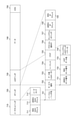
- FIG. 4 is a diagram showing an example of a format configuration of a packet output from the high frequency signal receiving device 100 according to the first embodiment of the present technology.
- UDP is adopted as the protocol of the packet output from the high frequency signal receiving device 100. Since UDP does not perform retransmission processing or flow control in the event of an error, transmission efficiency is higher than that of TCP, and high-speed transmission can be expected. In this embodiment, it is assumed that UDP is adopted because a small number of bit errors can be dealt with at the time of re-radiation and the data at the time of CRC error can be used.
- Ethernet header 710 the Ethernet header 710, the IP header 720, the UDP header 730, and the CRC750 are added to the data 740 transmitted as a packet.
- the Ethernet header 710 stores the destination MAC address 711, the source MAC address 712, and the ether type 713.
- the destination MAC address 711 is a field indicating the MAC address of the destination device of this packet, that is, the high frequency signal re-radiating device 300.
- the source MAC address 712 is a field indicating the MAC address of the source device of this packet, that is, the high frequency signal receiving device 100.
- Ethertype 713 is a field indicating a number for identifying an upper layer protocol. In this example, "0800" is shown because IP (Internet Protocol) is assumed as the upper layer protocol.
- the IP header 720 stores the version / header length 721, service type 722, data length 723, sequence 724, flag 725, protocol identifier 726, checksum 727, source IP address 728, and destination IP address 729.
- the version / header length 721 is a field in which the first 4 bits indicate the version and the latter 4 bits indicate the header length. As the version, for example, if it is IPv4, "4" is shown. The header length is in units of 4 bytes, and if it is 20 bytes, it indicates "5".
- the service type 722 is a field indicating the service type, and the IP precision value indicating the priority is stored in the upper 3 bits thereof.
- the data length 723 is a field indicating the UDP / IP data length including the header.
- Sequence 724 is an identifier that is incremented for each packet. This makes it possible to identify the packet when it is divided in the middle.
- Flag 725 is a field for storing information about the fragment.
- the protocol identifier 726 is a field that identifies the protocol, and in the case of UDP, indicates "11".
- the checksum 727 is a field for storing the checksum of the IP header.
- the source IP address 728 is a field indicating the source IP address. In this embodiment, any of multicast, unicast, and broadcast may be selected. In the case of multicast, this source IP address 728 indicates an all-F value.
- the destination IP address 729 is a field indicating the destination IP address.
- the UDP header 730 stores the source port number 731, the destination port number 732, the UDP data length 733, and the checksum 734.
- the source port number 731 is a field indicating the port number of the source.
- the destination port number 732 is a field indicating the destination port number.
- the UDP data length 733 is a field indicating the length of the UDP data 740 in hexadecimal.
- the checksum 734 is a field indicating the checksum of the UDP header 730 and the data 740.
- the CRC750 is a field for storing an error detection code by a cyclic redundancy check (CRC: Cyclic Redundancy Check).
- the data 740 includes an intermediate frequency signal of the GNSS signal and additional information.
- the additional information includes, for example, packet serial numbers, timing information, control codes, and the like.
- the serial number of the packet is a number assigned to each packet in order.
- the timing information indicates the time division as the timing.
- the control code selects a destination when there are a plurality of transmission destinations.
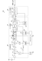
- FIG. 5 is a diagram showing a configuration example of the high frequency signal re-radiating device 300 according to the first embodiment of the present technology.
- the high frequency signal re-radiating device 300 includes an Ethernet control unit 310, a packet interpretation unit 320, and an RF transmission unit 330. Further, the high frequency signal re-radiating device 300 includes a temperature-compensated crystal oscillator 340 and a host computer 350.
- the temperature-compensated crystal oscillator 340 outputs a signal having an oscillation frequency such as 16.368 MHz or 26 MHz.
- the output of the temperature-compensated crystal oscillator 340 is distributed to each unit of the packet interpretation unit 320 via the buffer 337 of the RF transmission unit 330.
- the Ethernet control unit 310 controls the MAC layer 311 and the physical layer (PHY layer) 312.
- the Ethernet control unit 310 receives a packet from the communication path 200 in synchronization with the clock signal from the clock generation unit 328 described later.
- the packet interpretation unit 320 includes a packet analysis unit 321, a FIFO 322, a FIFO remaining amount check unit 323, a parallel / serial converter 324, a rate adjustment unit 325, a low-pass filter 326, a frequency divider 327, a clock generation unit 328, and a control unit 329.
- the frequency divider 327 is a circuit that divides the clock signal distributed from the buffer 337 by a factor of N.
- the clock signal distributed from the buffer 337 is supplied to the rate adjustment unit 325 and the low-pass filter 326.
- the clock signal divided by the frequency divider 327 is used for the read operation of the parallel / serial converter 324 and the FIFA 322.
- the packet analysis unit 321 analyzes the received packet and performs predetermined processing. That is, the packet analysis unit 321 identifies the packet addressed to its own device and extracts the data portion of the intermediate frequency signal. Then, when the packet analysis unit 321 detects the packet omission from the serial number, the packet analysis unit 321 interpolates the dummy data (for example, all zero) of the missing portion so as not to become a discontinuous signal. As a result, synchronization can be maintained in UDP transmission without retransmission control.
- the FIFO 322 is a FIFO buffer that holds the packet output from the packet analysis unit 321.
- the packet analysis unit 321 outputs a write request to the FIFA 322 and writes the packet to the FIFA 322.
- the serial / parallel converter 121 of the high-frequency signal receiver 100 does not interrupt the output of the parallel / serial converter 324. Can maintain the same data rate as the input to.
- FIFA 322 is an example of the buffer memory described in the claims.
- the clock generation unit 328 generates a clock signal used before the write operation to the FIFA 322. That is, the write operation to the Ethernet control unit 310, the packet analysis unit 321, and the FIFA 322 operates in synchronization with the clock signal from the clock generation unit 328.
- the parallel / serial converter 324 is a circuit that converts the data of the parallel signal held in the FIFA 322 into an intermediate frequency signal of the serial signal.
- the parallel / serial converter 324 outputs a read request to the FIFA 322 and reads out the data held in the FIFA 322.
- this data for example, 8-bit width data and a signal of 0.5115 Mbps are assumed.
- the FIFO remaining amount check unit 323 checks the remaining amount of data held in the FIFO 322 and outputs it to the rate adjustment unit 325.
- the rate adjusting unit 325 adjusts the rate of the intermediate frequency signal output from the parallel / serial converter 324 according to the remaining amount of data output from the FIFO remaining amount check unit 323. Since the source oscillator of the sampling clock in the high-frequency signal receiving device 100 and the clock in the high-frequency signal re-radiating device 300 are different between the temperature-compensated crystal oscillators 140 and 340, a frequency shift may occur. Therefore, based on the remaining amount of FIFO data detected by the FIFO remaining amount check unit 323, the frequency difference is adjusted by the rate adjusting unit 325 from the excess or deficiency.
- the rate adjustment unit 325 sometimes performs an operation of thinning out data for one clock according to the change in the remaining amount.
- the rate adjusting unit 325 sometimes inserts a zero value for one clock according to the change in the remaining amount.
- the packet interpretation unit 320 performs synchronous processing. That is, the packet analysis unit 321 inserts dummy data for missing packets, and the rate adjustment unit 325 adjusts the frequency difference to perform synchronization processing when performing packet transmission with the high frequency signal receiving device 100.
- the low-pass filter 326 is a filter that removes the high frequency component of the output of the rate adjustment unit 325 and outputs it as an intermediate frequency signal IF_out. As a result, it is possible to suppress the transmission spectrum of the intermediate frequency signal from widening.
- the intermediate frequency signal IF_out for example, a signal of 4.092 Mbps is assumed by IQ modulation of a total of 16 bits of 8 bits for I channel and 8 bits for Q channel.
- the control unit 329 controls the entire packet interpretation unit 320.
- the RF transmission unit 330 includes a DA converter 331, a low-pass filter 332, a variable gain amplifier 333, a mixer 334, a low noise amplifier 335, a phase-locked loop 336, a buffer 337, and a control unit 339.
- the DA converter (DAC: Digital-to-Analog Converter) 331 is a circuit that converts the intermediate frequency signal IF_out of the digital signal output from the packet interpretation unit 320 into an analog signal.
- the low-pass filter 332 is a filter that removes high-frequency components from the output of the DA converter 331.
- the variable gain amplifier 333 is an amplifier that amplifies the output of the low-pass filter 332 with a variable gain.
- the phase-locked loop 336 is a circuit that generates a phase-locked signal based on the output of the temperature-compensated crystal oscillator 340.
- the mixer 334 is a circuit that converts a high-frequency signal amplified by the variable gain amplifier 333 into a high-frequency signal by mixing the signal from the phase-locked loop 336.
- the low noise amplifier 335 is an amplifier that amplifies the high frequency signal output from the mixer 334.
- the buffer 337 is a circuit that amplifies the output of the temperature-compensated crystal oscillator 340 and distributes it as a clock signal.
- the control unit 339 controls the entire RF transmission unit 330.
- the host computer 350 controls the operation of the high-frequency signal re-radiating device 300.
- the packet interpretation unit 320 is connected to the control unit 329, and the RF transmission unit 330 is connected to the control unit 339 to perform various settings. Performs monitor operation, communication, etc.
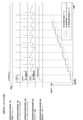
- FIG. 6 is a diagram showing an operation example of the wireless system without packet loss according to the first embodiment of the present technology.
- the numerical values shown here are examples.
- reception is started by the high frequency signal receiving device 100, and an intermediate frequency signal is generated at a rate of, for example, 2.046 Mbps. Then, in the high frequency signal receiving device 100, it is assumed that packets are output at a constant output interval T, for example, in units of 128 bytes. This output interval can be controlled by the high frequency signal receiving device 100.
- the high-frequency signal re-radiating device 300 receives a packet via the communication path 200, but the delay time varies depending on the network operation of the communication path 200.
- the high frequency signal re-radiating device 300 adjusts the rate by temporarily holding the packet in the FIFA 322.
- the packet input interval Ti and the output delay Do the difference is zero or more, that is, Ti-Do ⁇ 0 If is always true, the data size of FIFA 322 is sufficient to be 256 bytes or less.
- the difference exceeds the output interval T, that is, Ti-Do> T. Therefore, an underflow in which the FIFA 322 becomes empty occurs, and interpolation processing is required. Therefore, the data output from the FIFA 322 is controlled to be delayed.
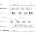
- FIG. 7 is a diagram showing an operation example of the wireless system with packet loss in the first embodiment of the present technology.
- the numerical values shown here are the same as those shown in the above example.
- the packet input delay is assumed to be T or less, but if it exceeds T, the size and output delay of FIFA 322 are increased.
- FIG. 8 is a diagram showing a modified example of the wireless system according to the first embodiment of the present technology.
- only one high-frequency signal re-radiating device 300 is arranged indoors, but a plurality of high-frequency signal re-radiating devices 300 may be arranged.
- a local area network (LAN) 201 as the communication path 200 to connect a plurality of high frequency signal re-radiating devices 300.
- the plurality of GNSS receivers 510 that receive the GNSS signal from one high-frequency signal re-radiating device 300 operate synchronously, but also the GNSS signal from the other high-frequency signal re-radiating device 300 is received. Synchronous operation with other GNSS receivers 510 is also possible.
- the GNSS signal received by the high frequency signal receiving device 100 is packetized and transmitted through the communication path 200, and is returned to the GNSS signal by the high frequency signal reradiating device 300 and reradiated. do.
- the GNSS receiver 510 can use the GNSS signal even indoors.
- the GNSS signal is packetized and transmitted as it is, but in the subsequent embodiments, an indoor positioning signal is generated and the indoor positioning signal is packetized and transmitted.
- This indoor positioning signal is a signal carrying time information synchronized with a time pulse 1PPS (Pulse Per Second) accurately synchronized with a GNSS clock.
- 1PPS is a pulse signal sequence at 1-second intervals synchronized with the time of the highly accurate GNSS satellite 10, and is a signal synchronized with the positive second.
- the format of the indoor positioning signal for example, an iPNT (indoor Position, Navigation, Timing) format may be used, or a unique format may be used.
- the GNSS receiver 510 can receive not only the GNSS signal but also this indoor positioning signal. Since the overall configuration of the wireless system is the same as that of the first embodiment described above, detailed description thereof will be omitted.
- FIG. 9 is a diagram showing a configuration example of a wireless system according to a second embodiment of the present technology.
- the high frequency signal receiving device 100 includes an RF receiving positioning unit 160, a packet conversion unit 170, and an Ethernet control unit 130.
- the RF reception positioning unit 160 performs positioning based on the GNSS signal, which is a high-frequency signal received via the antenna 109, and acquires accurate time information synchronized with the GNSS satellite 10.
- the RF reception positioning unit 160 outputs the acquired time information and the time pulse 1PPS.
- the packet conversion unit 170 generates an intermediate frequency signal of an indoor positioning signal from the time information output from the RF reception positioning unit 160 and 1PPS, and converts it into a packet for transmission to Ethernet.
- the Ethernet control unit 130 is the same as the first embodiment described above, and sends the packet converted by the packet conversion unit 170 to the communication path 200.
- the communication path 200 and the high frequency signal re-radiating device 300 are the same as those in the first embodiment described above.
- the high frequency signal re-radiating device 300 transmits the indoor positioning signal as a high frequency signal instead of the GNSS signal itself.
- the indoor positioning signal in this case can use the same frequency as the GNSS signal (for example, 1575.42 MHz). Even in this case, since the signal used for re-radiation is a weak radio wave, it does not affect other devices.
- the GNSS receiver 510 can receive the indoor positioning signal transmitted from the high frequency signal re-radiating device 300 and perform time synchronization based on the head timing and time information of the received message.
- FIG. 10 is a diagram showing a configuration example of the high frequency signal receiving device 100 according to the second embodiment of the present technology.
- the high frequency signal receiving device 100 in the second embodiment includes an RF receiving positioning unit 160, a packet conversion unit 170, and an Ethernet control unit 130. Further, the high frequency signal receiving device 100 includes a temperature-compensated crystal oscillator 140 and a host computer 150.
- the RF reception positioning unit 160 has a low noise amplifier 111, a mixer 112, a low-pass filter 113, a variable gain amplifier 114, an AD converter 115, and a phase-locked loop 116, similarly to the RF reception unit 110 in the first embodiment described above. , Buffer 117, frequency divider 118 and control unit 119. Further, the RF reception positioning unit 160 further includes a GNSS positioning engine 161.
- the GNSS positioning engine 161 performs positioning based on the received GNSS signal, and outputs accurate time information synchronized with the time of the GNSS satellite 10 and 1PPS.
- the time information for example, a text sentence in a format conforming to the NMEA 0183 standard may be output.
- the time information may include the date and hours, minutes and seconds of UTC (Coordinated Universal Time).
- the packet conversion unit 170 includes a FIFA 122, a packet generation unit 123, a frequency divider 124, a clock generation unit 128, and a control unit 129, similarly to the packet conversion unit 120 in the first embodiment described above. Further, the packet conversion unit 170 includes an indoor positioning signal generation unit 171.
- the indoor positioning signal generation unit 171 generates an intermediate frequency signal of the indoor positioning signal based on the time information output from the GNSS positioning engine 161 and 1PPS.
- As the intermediate frequency signal of this indoor positioning signal for example, a 1-bit 2.046 Mbps signal is assumed.
- the indoor positioning signal generated by the indoor positioning signal generation unit 171 is held in the FIFA 122 according to a write request.
- the write operation of the indoor positioning signal generation unit 171 and the FIFA 122 operates in synchronization with the clock signal from the frequency divider 124.
- the packet generation unit 123 outputs a read request to the FIFA 122, reads the data held in the FIFA 122, and generates a packet.
- the packet generation unit 123 adds the time of the packet transmission start timing as information in packetization, the high frequency signal re-radiating device 300 can obtain the time at the time of packet transmission by analyzing the packet.
- the high frequency signal re-radiating device 300 analyzes the packet.
- the timing of 1PPS can be obtained. For example, assuming that the intermediate frequency signal of the packet is 128 bytes, a total of 11 bits, that is, 1 bit indicating the presence or absence of 1PPS timing and 10 bits of 1PPS timing may be added.
- FIG. 11 is a diagram showing an operation example of the wireless system according to the second embodiment of the present technology.
- the indoor positioning signal generation unit 171 that receives 1PPS and time information configures a counter that finely ticks the 1PPS interval, and can tick the accurate time by setting the time according to the timing of 1PPS from the time information.
- the packet generation unit 123 generates message data including an accurate time according to the format of the indoor positioning signal, and packets the message data and the EOR of the diffusion code as an intermediate frequency signal.
- the message data includes a preamble, a time at the beginning of the message, position information, delay correction information, and the like. In this example, it is assumed that the time information is updated once every 3 seconds.
- the Ethernet control unit 130 outputs the packetized signal to the communication path 200.
- the Ethernet transmission rate of the communication path 200 is sufficiently higher than the rate of the original intermediate frequency signal, the Ethernet transmission has a long idle time.
- the high frequency signal re-radiating device 300 extracts the packet from the Ethernet input and returns the packet to the original intermediate frequency signal. Even if the packet input interval varies, the FIFA 322 in the packet interpretation unit 320 absorbs the variation, and the intermediate frequency signal is reproduced at a constant rate without interruption. Further, when the timing information of 1PPS is added to the packet, 1PPS can be easily reproduced.
- the indoor positioning signal is generated from the GNSS signal received by the high frequency signal receiving device 100, packetized and transmitted by the communication path 200, and the high frequency signal reradiating device 300. Return to the indoor positioning signal and re-radiate. As a result, the GNSS receiver 510 can use the indoor positioning signal even indoors.
- the indoor positioning signal obtained from the GNSS signal is packetized and transmitted, but in the third embodiment, the high frequency signal receiving device 100 is combined with the high frequency signal reradiating device 300. The delay time between them is measured and the corrected time information is reflected in the packet.
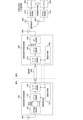
- FIG. 12 is a diagram showing a configuration example of a wireless system according to a third embodiment of the present technology.
- the high frequency signal receiving device 100 includes a delay measuring unit 181. Further, the high frequency signal re-radiating device 300 includes a delay measuring unit 382. Other than that, the configuration is basically the same as that of the second embodiment described above.
- the delay measurement unit 181 measures the round-trip time by bidirectionally communicating the delay measurement packet with the delay measurement unit 382, and obtains the delay correction amount.
- the packet conversion unit 170 shifts the beginning of the message data forward by this delay correction amount. As a result, the delay in the GNSS receiver 510 is corrected, and the accuracy of time synchronization can be improved. Further, the packet conversion unit 170 can correct the delay time by adding the obtained delay time to the packet of the indoor positioning signal.
- FIG. 13 is a diagram showing a sequence example of delay time measurement in the third embodiment of the present technology.
- the delay measurement packet used for bidirectional communication is composed of a header and measurement information.
- the measurement information includes an identification number, a transmission start time stamp, and a reception start time stamp.
- the high frequency signal re-radiating device 300 delays the output of the intermediate frequency signal so that the total delay amount becomes a constant value with respect to the obtained delay correction amount, for example. As a result, the delay in the GNSS receiver 510 becomes a constant value, and the accuracy of time synchronization can be improved.
- FIG. 14 is a diagram showing an operation example of the wireless system according to the third embodiment of the present technology.
- the high frequency signal receiving device 100 transmits the delay measurement packet # 1 between the packets of the indoor positioning signal.
- the high frequency signal re-radiating device 300 adds a time stamp of T1 at the start of reception and T2 at the start of transmission, and returns the delay measurement packet # 2.
- the delay measurement is performed multiple times in the figure, it does not change as long as the packet is continuously transmitted, so only the first one is sufficient.
- the high frequency signal receiving device 100 cannot detect even if a large number of packet losses are continuously generated in the high frequency signal reradiating device 300. In such a case, it is desirable that the high-frequency signal receiving device 100 periodically performs delay measurement in order for the high-frequency signal re-radiating device 300 to recover.
- the delay measurement unit 181 measures the round-trip time by bidirectionally communicating the delay measurement packet with the delay measurement unit 382, and the delay time. Can be corrected.
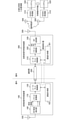
- FIG. 15 is a diagram showing a configuration example of a wireless system according to a fourth embodiment of the present technology.
- the high frequency signal receiving device 100 includes a delay measuring unit 182. Further, the high frequency signal re-radiating device 300 includes a delay measuring unit 381. Other than that, the configuration is basically the same as that of the second embodiment described above.
- the delay measurement unit 381 measures the round-trip time by bidirectionally communicating the delay measurement packet with the delay measurement unit 182, and obtains the delay correction amount.
- the high frequency signal re-radiating device 300 delays the output of the intermediate frequency signal so that the total delay amount becomes a constant value with respect to the obtained delay correction amount, for example. As a result, the delay in the GNSS receiver 510 becomes a constant value, and the accuracy of time synchronization can be improved.
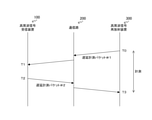
- FIG. 16 is a diagram showing a sequence example of delay time measurement in the fourth embodiment of the present technology.
- the delay measurement unit 381 of the high-frequency signal re-radiation device 300 measures the round-trip time of the delay measurement packet by bidirectional communication. That is, the delay measurement unit 381 measures the time T3 when the delay measurement packet # 2 is received from the high frequency signal receiving device 100 after the delay measurement packet # 1 is output to the communication path 200 at the time T0. Further, the time T1 at which the delay measurement packet # 1 is received by the high frequency signal receiving device 100 and the time T2 at which the delay measurement packet # 1 is output to the communication path 200 are acquired. Thereby, the round-trip time TX can be acquired. Thereby, similarly to the third embodiment described above, the delay correction amount DA can be acquired based on the value of half of the round trip time TX.
- FIG. 17 is a diagram showing an operation example of the wireless system according to the fourth embodiment of the present technology.
- the high frequency signal re-radiating device 300 transmits the delay measurement packet # 1 between the packets of the indoor positioning signal.
- the high frequency signal receiving device 100 adds a time stamp of T1 at the start of reception and T2 at the start of transmission, and returns the delay measurement packet # 2.
- the packet interpretation unit 320 delays the output of the intermediate frequency signal, for example, by setting the delay amount ⁇ so that the total delay amount becomes a constant value with respect to the obtained delay correction amount with reference to 1PPS.
- the delay measurement is performed multiple times in the figure, it does not change as long as the packet is continuously transmitted, so only the first one is sufficient. However, when a large number of packet losses occur continuously in the high-frequency signal re-radiating device 300, it is desirable to perform delay measurement in order for the high-frequency signal re-radiating device 300 to recover.
- the delay measurement unit 381 measures the round-trip time by bidirectionally communicating the delay measurement packet with the delay measurement unit 182, and the delay time. Can be corrected.
- the output of the intermediate frequency signal is delayed with reference to 1PPS, but in the fifth embodiment, delay correction is performed from the packet delay without using 1PPS.
- FIG. 18 is a diagram showing a configuration example of a wireless system according to a fifth embodiment of the present technology.
- the fifth embodiment has the same configuration as the fourth embodiment described above.
- the high frequency signal re-radiating device 300 includes a packet interpreting unit 360, and the process of delaying the output of the intermediate frequency signal is different.
- the delay measurement unit 381 measures the round-trip time by bidirectionally communicating the delay measurement packet with the delay measurement unit 182, and obtains the delay correction amount.
- the content of the delay measurement is the same as that of the fourth embodiment described above.
- FIG. 19 is a diagram showing an operation example of the wireless system according to the fifth embodiment of the present technology.
- the packet interpretation unit 360 generates an indoor positioning signal carrying delay-corrected time information based on the time information obtained from the packetized indoor positioning signal and the correction delay amount measured by the delay measurement unit 381. That is, the packet interpretation unit 360 delays the output of the intermediate frequency signal by setting the delay amount ⁇ so that the total delay amount becomes a constant value with respect to the obtained delay correction amount with reference to the packet transmission start time. ..
- the delay time can be corrected from the packet delay without using 1PPS.
- the delay correction amount is obtained by bidirectionally communicating the delay measurement packet, but in the sixth embodiment, the delay amount is adjusted by using the beacon synchronized with 1PPS. I do.
- FIG. 20 is a diagram showing a configuration example of a wireless system according to a sixth embodiment of the present technology.
- the high frequency signal receiving device 100 includes a beacon control unit 191 and a beacon transmission unit 192. Further, the high frequency signal re-radiating device 300 includes a beacon receiving unit 393. Other than that, the configuration is basically the same as that of the second embodiment described above.
- the beacon control unit 191 generates a beacon synchronized with 1PPS output from the RF reception positioning unit 160.
- the beacon transmission unit 192 transmits a beacon synchronized with this 1PPS.
- the beacon receiving unit 393 receives the beacon transmitted from the beacon transmitting unit 192 and supplies the beacon timing synchronized with 1PPS to the packet interpreting unit 320.
- FIG. 21 is a diagram showing an operation example of the wireless system according to the sixth embodiment of the present technology.
- the packet interpretation unit 320 starts from 1PPS and delays the output of the intermediate frequency signal so that the delay amount becomes a constant value with respect to the beacon timing synchronized with 1PPS, for example. As a result, the delay in the GNSS receiver 510 becomes a constant value, and the accuracy of time synchronization can be improved.
- the delay amount can be adjusted by using the beacon synchronized with 1PPS.
- the GNSS receiver 510 discriminates between direct reception and re-radiation reception from the satellite.
- the output of the AD converter of the GNSS receiver 510 is at a constant level because the GNSS signal is lower than the thermal noise, but in the case of re-radiation, the distance from the retransmitter and the orientation of the antenna of the AD converter. The output fluctuates over time. Therefore, identification is performed using that property.
- an identification signal such as a continuous wave (CW: Continuous Wave) such as a sine wave having a specific frequency may be added and re-radiated, and the GNSS receiver 510 may detect and identify the signal. Since many GNSS receivers in recent years have a built-in FFT function for detecting an interfering wave, the identification signal can be detected by using the function.
- CW Continuous Wave
- the identification signal can be detected by using the function.
- FIG. 22 is a diagram showing a configuration example of a wireless system according to a seventh embodiment of the present technology.
- a in the figure shows a configuration example when an identification signal is applied in the high frequency signal receiving device 100.
- the high frequency signal receiving device 100 includes an identification signal generation unit 190.
- the identification signal generation unit 190 generates an identification signal and outputs it to the packet conversion unit 170.
- the packet conversion unit 170 adds an identification signal to the packet accordingly.
- Reference numeral b in the figure shows a configuration example when an identification signal is applied in the high frequency signal re-radiating device 300.
- the high frequency signal re-radiating device 300 includes an identification signal generation unit 390.
- the identification signal generation unit 390 generates an identification signal and outputs it to the mixer 391.
- the mixer 391 outputs an intermediate frequency signal to which the identification signal is added to the RF transmission unit 330.
- FIG. 23 is a diagram showing an example of a spectrum of an intermediate frequency signal including an identification signal in the seventh embodiment of the present technology.
- the spectrum of the intermediate frequency signal is formed between the frequencies f1 and f2, and the two wave identification signals are provided at the frequencies f1 and f2.
- a two-wave identification signal is assumed, but the number of identification signals is not limited. Increasing the number of identification signals increases the scale of the generation circuit, but can reduce false positives. Further, if the frequency of the identification signal is set out of the band, the influence on the reception sensitivity can be suppressed.
- a diffusion signal with a PRN (Pseudo-Random Noise) code that is not assigned to any satellite may be used in addition to the continuous wave.
- PRN Physical-Random Noise
- indoor / outdoor discrimination is performed in the GNSS receiver 510 by adding the identification signal generated by the identification signal generation unit 190 or the identification signal generation unit 390. It can be carried out.
- the processing procedure described in the above-described embodiment may be regarded as a method having these series of procedures, or as a program for causing a computer to execute these series of procedures or as a recording medium for storing the program. You may catch it.
- this recording medium for example, a CD (Compact Disc), MD (MiniDisc), DVD (Digital Versatile Disc), memory card, Blu-ray Disc (Blu-ray (registered trademark) Disc) and the like can be used.
- the present technology can have the following configurations.
- a packet receiving unit that receives a packet generated based on the first high-frequency signal, and A packet interpreter that performs synchronous processing on the packet to generate an intermediate frequency signal
- a high-frequency signal re-radiating device including a high-frequency signal transmission unit that converts the intermediate frequency signal into a second high-frequency signal and transmits the signal.
- the packet interpreting unit is The buffer memory that holds the packet and The (1) or (2) or (2) or (2) or (2) or (2) having the high frequency signal transmission unit and a rate adjusting unit for outputting the intermediate frequency signal according to a common clock frequency by reading the packet from the buffer memory based on the remaining amount of the buffer memory. ).
- High frequency signal re-radiating device is Further provided with a delay measuring unit for measuring the delay time with another device that generated the packet. The high-frequency signal re-radiating device according to any one of (1) to (3), wherein the packet interpreting unit generates the intermediate frequency signal based on the delay time.
- the high-frequency signal re-radiating device (4), wherein the delay measuring unit measures the delay time by transmitting and receiving a delay measurement packet to and from the other device.
- the beacon receiving unit is further provided.
- the high-frequency signal re-radiating device according to any one of (1) to (3), wherein the packet interpreting unit generates the intermediate frequency signal based on the reception timing of the beacon signal.
- the high-frequency signal transmission unit according to any one of (1) to (6) above, wherein the high-frequency signal transmission unit transmits an identification signal for identifying the re-radiated signal in addition to the second high-frequency signal. High frequency signal re-radiating device.
- the high frequency signal re-radiating device includes a GNSS (Global Navigation Satellite System) signal.
- the packet includes an indoor positioning signal carrying time information synchronized with the synchronization pulse.
- a high-frequency signal receiving unit that receives a high-frequency signal and generates an intermediate frequency signal,
- a packet generator that generates a packet based on the high-frequency signal,
- a high-frequency signal receiving device including a packet output unit that outputs the generated packet to a communication path.
- the high-frequency signal receiving device wherein the packet generation unit receives a GNSS signal as the high-frequency signal and generates the packet including the GNSS signal.
- the packet generation unit receives a GNSS signal as the high frequency signal, acquires a synchronization pulse from the GNSS signal, and includes an indoor positioning signal carrying time information synchronized with the synchronization pulse.
- the high frequency signal receiving device according to (10) above, which generates a packet.
- the high-frequency signal receiving device further comprising a beacon transmitting unit that transmits a beacon at a timing synchronized with the synchronization pulse.
- the high-frequency signal receiving device 10
- the packet generation unit generates the packet based on the delay time.
- the delay measuring unit measures the delay time by transmitting and receiving delay measurement packets to and from the other device.
- the packet generation unit generates the packet by adding an identification signal for identifying the signal to be re-radiated. ..
- a high-frequency signal receiving unit that receives a first high-frequency signal and generates a first intermediate frequency signal, a packet generating unit that generates a packet based on the first high-frequency signal, and the generated packet.
- a high-frequency signal receiver equipped with a packet output unit that outputs A packet receiving unit that receives the packet via the communication path, a packet interpreting unit that performs synchronization processing on the packet to generate a second intermediate frequency signal, and a second high frequency signal using the second intermediate frequency signal.
- a high-frequency signal re-radiator equipped with a high-frequency signal transmitter that converts it into a signal and transmits it,
- a wireless system including a wireless receiver that receives the second high frequency signal and performs positioning or time synchronization based on the second high frequency signal.
- GNSS satellite 100 High frequency signal receiver 109 Antenna 110 RF receiver 111 Low noise amplifier (LNA) 112 Mixer 113 Low Pass Filter (LPF) 114 Variable Gain Amplifier (VGA) 115 AD converter (ADC) 116 Phase-locked loop (PLL) 117 Buffer 118 Divider 119 Control Unit 120 Packet Converter 121 Serial / Parallel Converter 122 FIFO 123 Packet generator 124 Divider 128 Clock generator 129 Control unit 130 Ethernet control unit 140 Temperature-compensated crystal oscillator (TCXO) 150 Host computer 160 RF reception positioning unit 161 GNSS positioning engine 170 Packet conversion unit 171 Indoor positioning signal generation unit 181 and 182 Delay measurement unit 190 Identification signal generation unit 191 Beacon control unit 192 Beacon transmitter 200 Communication path 300 High frequency signal re-radiator 310 Ethernet control unit 320 Packet interpretation unit 321 Packet analysis unit 322 FIFA 323 FIFO remaining amount check unit 324 Parallel / serial converter 325 Rate
Landscapes
- Engineering & Computer Science (AREA)
- Computer Networks & Wireless Communication (AREA)
- Signal Processing (AREA)
- Radar, Positioning & Navigation (AREA)
- Remote Sensing (AREA)
- Physics & Mathematics (AREA)
- General Physics & Mathematics (AREA)
- Mobile Radio Communication Systems (AREA)
- Synchronisation In Digital Transmission Systems (AREA)
Abstract
屋外で利用されるGNSS(Global Navigation Satellite System)受信機を屋内においても利用可能にする。 高周波信号受信部は、第1の高周波信号を受信して第1の中間周波数信号を生成する。パケット生成部は、第1の高周波信号に基づいてパケットを生成する。パケット出力部は、生成されたパケットを通信路に出力する。パケット受信部は、通信路を介してパケットを受信する。パケット解釈部は、パケットについて同期処理を行って第2の中間周波数信号を生成する。高周波信号送信部は、第2の中間周波数信号を第2の高周波信号に変換して送信する。無線受信機は、第2の高周波信号を受信して、第2の高周波信号に基づいて測位または時刻同期を行う。
Description
本技術は、無線システムに関する。詳しくは、測位または時刻同期を行うための高周波信号再放射装置、高周波信号受信装置、および、無線システムに関する。
GNSS(Global Navigation Satellite System)信号を受信するGNSS受信機は、位置情報だけでなく、GNSSの高精度な時計に同期した正確な時刻を得ることができ、複数のGNSS受信機を用いて1マイクロ秒以下で時刻同期することができる。このGNSS受信機は、屋内では衛星からのGNSS信号を受信できないことが多いため、そのままでは利用することができない。そこで、衛星からの信号をサーバにおいて受信して、端末装置に時刻情報および空間情報を配信するシステムが提案されている(例えば、特許文献1参照。)。
上述の従来技術では、屋内の端末における時刻情報および空間情報の利用を図っている。しかしながら、この従来技術では、ローカルエリアネットワークに接続する端末における利用を想定しており、通常のGNSS受信機では利用することができない。また、従来技術において想定する端末を屋外に移動した場合には、時刻情報および空間情報を利用することができなくなる。
本技術はこのような状況に鑑みて生み出されたものであり、屋外で利用されるGNSS受信機を屋内においても利用可能にすることを目的とする。
本技術は、上述の問題点を解消するためになされたものであり、その第1の側面は、第1の高周波信号に基づいて生成されたパケットを受信するパケット受信部と、上記パケットについて同期処理を行って中間周波数信号を生成するパケット解釈部と、上記中間周波数信号を第2の高周波信号に変換して送信する高周波信号送信部とを具備する高周波信号再放射装置である。これにより、受信したパケットから得られた第2の高周波信号を再放射するという作用をもたらす。
また、この第1の側面において、上記パケット解釈部は、上記パケットの欠落を検出して上記欠落部分にダミーデータを内挿するようにしてもよい。これにより、パケットが不連続信号にならないようにして同期を保つという作用をもたらす。
また、この第1の側面において、上記パケット解釈部は、上記パケットを保持するバッファメモリと、上記バッファメモリの残量に基づいて上記バッファメモリから上記パケットを読み出して、上記高周波信号送信部と共通のクロック周波数に従って上記中間周波数信号を出力するレート調整部とを備えるようにしてもよい。これにより、パケットのレートを調整して同期を保つという作用をもたらす。
また、この第1の側面において、上記パケットを生成した他の装置との間の遅延時間を計測する遅延計測部をさらに具備し、上記パケット解釈部は、上記遅延時間に基づいて上記中間周波数信号を生成するようにしてもよい。これにより、時刻同期の精度を向上させるという作用をもたらす。この場合において、上記遅延計測部は、遅延計測パケットを上記他の装置との間で送受信することにより上記遅延時間を計測するようにしてもよい。これにより、遅延計測パケットを用いて時刻同期の精度を向上させるという作用をもたらす。
また、この第1の側面において、時刻同期したビーコン信号を受信するビーコン受信部をさらに具備し、上記パケット解釈部は、上記ビーコン信号の受信タイミングに基づいて上記中間周波数信号を生成するようにしてもよい。これにより、ビーコン信号を用いて時刻同期の精度を向上させるという作用をもたらす。
また、この第1の側面において、上記高周波信号送信部は、再放射された信号であることを識別するための識別信号を上記第2の高周波信号に加えて送信するようにしてもよい。これにより、第2の高周波信号の受信側において、再放射された信号であることを識別させるという作用をもたらす。
また、この第1の側面において、上記パケットは、GNSS信号を含むようにしてもよく、また、同期化パルスに同期した時刻情報を載せた屋内測位信号を含むようにしてもよい。
また、本技術の第2の側面は、高周波信号を受信して中間周波数信号を生成する高周波信号受信部と、上記高周波信号に基づいてパケットを生成するパケット生成部と、上記生成されたパケットを通信路に出力するパケット出力部とを具備する高周波信号受信装置である。これにより、受信した高周波信号をパケット化して通信路に出力するという作用をもたらす。
また、この第2の側面において、上記パケット生成部は、上記高周波信号としてGNSS信号を受信して、上記GNSS信号を含む上記パケットを生成するようにしてもよい。
また、この第2の側面において、上記パケット生成部は、上記高周波信号としてGNSS信号を受信して、上記GNSS信号から同期化パルスを取得して、上記同期化パルスに同期した時刻情報を載せた屋内測位信号を含む上記パケットを生成するようにしてもよい。
また、この第2の側面において、上記同期化パルスに同期したタイミングでビーコンを送信するビーコン送信部をさらに具備してもよい。
また、この第2の側面において、上記パケットを受信する他の装置との間の遅延時間を計測する遅延計測部をさらに具備し、上記パケット生成部は、上記遅延時間に基づいて上記パケットを生成するようにしてもよい。これにより、時刻同期の精度を向上させるという作用をもたらす。この場合において、上記遅延計測部は、遅延計測パケットを上記他の装置との間で送受信することにより上記遅延時間を計測するようにしてもよい。これにより、遅延計測パケットを用いて時刻同期の精度を向上させるという作用をもたらす。
また、この第2の側面において、上記パケット生成部は、再放射された信号であることを識別するための識別信号を加えて上記パケットを生成するようにしてもよい。これにより、再放射された高周波信号の受信側において、再放射された信号であることを識別させるという作用をもたらす。
また、本技術の第3の側面は、第1の高周波信号を受信して第1の中間周波数信号を生成する高周波信号受信部と、上記第1の高周波信号に基づいてパケットを生成するパケット生成部と、上記生成されたパケットを通信路に出力するパケット出力部とを備える高周波信号受信装置と、上記通信路を介して上記パケットを受信するパケット受信部と、上記パケットについて同期処理を行って第2の中間周波数信号を生成するパケット解釈部と、上記第2の中間周波数信号を第2の高周波信号に変換して送信する高周波信号送信部とを備える高周波信号再放射装置と、上記第2の高周波信号を受信して上記第2の高周波信号に基づいて測位または時刻同期を行う無線受信機とを具備する無線システムである。これにより、高周波信号受信装置において受信した第1の高周波信号をパケット化して伝送し、高周波信号再放射装置において第2の高周波信号を再放射して、無線受信機において測位または時刻同期を行うという作用をもたらす。
以下、本技術を実施するための形態(以下、実施の形態と称する)について説明する。説明は以下の順序により行う。
1.第1の実施の形態(GNSS信号をパケット化する例)
2.第2の実施の形態(屋内測位信号をパケット化する例)
3.第3の実施の形態(遅延時間を補正した屋内測位信号をパケット化する例)
4.第4の実施の形態(パケット受信側で1PPSを起点とした遅延時間で補正する例)
5.第5の実施の形態(パケット受信側でパケットの遅延量から遅延を補正する例)
6.第6の実施の形態(1PPSに同期したビーコンを受信して遅延量を調整する例)
7.第7の実施の形態(再放射信号の識別信号を追加する例)
1.第1の実施の形態(GNSS信号をパケット化する例)
2.第2の実施の形態(屋内測位信号をパケット化する例)
3.第3の実施の形態(遅延時間を補正した屋内測位信号をパケット化する例)
4.第4の実施の形態(パケット受信側で1PPSを起点とした遅延時間で補正する例)
5.第5の実施の形態(パケット受信側でパケットの遅延量から遅延を補正する例)
6.第6の実施の形態(1PPSに同期したビーコンを受信して遅延量を調整する例)
7.第7の実施の形態(再放射信号の識別信号を追加する例)
<1.第1の実施の形態>
[無線システム]
図1は、本技術の実施の形態における無線システムの一例の概要を示す図である。
[無線システム]
図1は、本技術の実施の形態における無線システムの一例の概要を示す図である。
この無線システムは、GNSS衛星10からのGNSS信号を受信するシステムであり、高周波信号受信装置100と、高周波信号再放射装置300と、GNSS受信機510とを備える。
高周波信号受信装置100は、GNSS衛星10からのGNSS信号を高周波信号として受信して所定のパケットを生成し、そのパケットを通信路200に出力する装置である。
高周波信号再放射装置300は、通信路200に出力されたパケットを受信して、そのパケットを解釈して高周波信号として再放射する装置である。高周波信号受信装置100は屋外に配置され、高周波信号再放射装置300は屋内に配置されることを想定する。
すなわち、高周波信号受信装置100が屋外でGNSS衛星10からのGNSS信号を受信して、パケットを通信路200により伝送し、高周波信号再放射装置300がそのパケットを高周波信号として屋内のGNSS受信機510に向けて再放射する。
GNSS受信機510は、屋外においてGNSS衛星10からのGNSS信号を受信して測位または時刻同期を行う機器である。ただし、この実施の形態では、GNSS受信機510が屋内においても利用されることを想定して、このGNSS受信機510に向けて高周波信号再放射装置300が高周波信号を再放射する。なお、GNSS受信機510は、特許請求の範囲に記載の無線受信機の一例である。
これにより、屋内および屋外の何れにおいてもGNSS受信機510を利用することができるようになる。
図2は、本技術の第1の実施の形態における無線システムの構成例を示す図である。
なお、以下では、高周波信号を「RF」(Radio Frequency)または「RF信号」と称する場合があり、中間周波数信号を「IF」(Intermediate Frequency)または「IF信号」と称する場合がある。
高周波信号受信装置100は、RF受信部110と、パケット変換部120と、イーサネット制御部130とを備える。
RF受信部110は、アンテナ109を介して受信した高周波信号であるGNSS信号をデジタルのIF信号に変換して出力するものである。
パケット変換部120は、IF信号をイーサネットに送出するためのパケットに変換するものである。
イーサネット制御部130は、パケット変換部120によって変換されたパケットを通信路200に送出するものである。なお、イーサネット制御部130は、特許請求の範囲に記載のパケット出力部の一例である。
通信路200は、有線および無線の何れであってもよい。有線の通信路200としては、例えば、イーサネットケーブル(例えば、100base-T)、PoE(Power over Ethernet)、電力線などが想定される。また、無線の通信路200としては、例えば、WiFi(登録商標)などが想定される。また、この通信路200において伝送されるパケットのプロトコルとしては、UDP(User Datagram Protocol)やTCP(Transmission Control Protocol)などが想定される。
なお、この通信路200におけるパケット伝送は、高周波信号受信装置100から高周波信号再放射装置300への一方向が主となるが、初期段階においてネットワーク内のネゴシエーションを行うため、全体として双方向通信を行うことになる。
高周波信号再放射装置300は、イーサネット制御部310と、パケット解釈部320と、RF送信部330とを備える。
イーサネット制御部310は、通信路200に出力されたパケットを受信するものである。なお、イーサネット制御部310は、特許請求の範囲に記載のパケット受信部の一例である。
パケット解釈部320は、受信したパケットを解釈してIF信号に戻す処理を行うものである。このパケット解釈部320は、パケット欠落時には、後述するように、例えばオールゼロのパケットを内挿する。
RF送信部330は、パケット解釈部320から出力されたデジタルのIF信号をRF信号に変換して、アンテナ399を介してGNSS信号を送信するものである。
この無線システムにおいて、屋外のアンテナ109では、例えば1575.42MHzのGNSS信号が受信される。このアンテナ109は、屋上など受信環境の良い場所が望ましいが、GNSS信号を受信できるのであれば、例えば屋内の窓際などであってもよい。
また、再放射のためのアンテナ399は、GNSS衛星10からのGNSS信号と同じ周波数(例えば1575.42MHz)を用いることができる。この場合、GNSS信号の再放射に用いられる信号は微弱電波で足りるため、他の機器に対して影響を与えるものではない。
GNSS受信機510には、端末などのシステム520が接続される。上述の再放射により、GNSS受信機510は正確な時刻および位置情報をシステム520に供給することができる。ここで、遅延に着目すると、アンテナ109からアンテナ399までの遅延は何れのシステム520でも共通である。一方、アンテナ399からGNSS受信機510のアンテナ509の距離の差は、最大でも20メートル程度と考えらえるため、遅延時間としては100ナノ秒以下である。したがって、これらの遅延を考慮しても、システム520の間においては精度の高い同期動作を行うことが可能である。
[高周波信号受信装置]
図3は、本技術の第1の実施の形態における高周波信号受信装置100の構成例を示す図である。
図3は、本技術の第1の実施の形態における高周波信号受信装置100の構成例を示す図である。
上述のように、高周波信号受信装置100は、RF受信部110と、パケット変換部120と、イーサネット制御部130とを備える。また、高周波信号受信装置100は、温度補償型水晶発振器(TCXO:Temperature-Compensated crystal Oscillator)140と、ホストコンピュータ150を備える。温度補償型水晶発振器140は、例えば、16.368MHzまたは26MHzなどの発振周波数による信号を出力する。
RF受信部110は、低雑音増幅器111、ミキサ112、ローパスフィルタ113、可変利得増幅器114、AD変換器115、位相同期回路116、バッファ117、分周器118および制御部119を備える。
低雑音増幅器(LNA:Low Noise Amplifier)111は、アンテナ109によって受信した高周波信号を増幅するアンプである。位相同期回路(PLL:Phase Locked Loop)116は、温度補償型水晶発振器140の出力に基づいて、位相同期した信号を生成する回路である。ミキサ112は、低雑音増幅器111によって増幅された高周波信号と位相同期回路116からの信号とを混合することによりベースバンド信号にダウンコンバートする回路である。
ローパスフィルタ(LPF:Low-pass filter)113は、ミキサ112から出力されたベースバンド信号の高周波成分を除去して帯域を制限するフィルタである。可変利得増幅器(VGA:Variable-Gain Amplifier)114は、ローパスフィルタ113の出力を、可変利得により増幅するアンプである。
バッファ117は、温度補償型水晶発振器140の出力を増幅してクロック信号として分配する回路である。分周器118は、バッファ117から分配されたクロック信号をN分の一に分周する回路である。
AD変換器(ADC:Analog-to-Digital Converter)115は、可変利得増幅器114によって増幅されたアナログ信号をデジタル信号に変換する回路である。このAD変換器115は、分周器118からのクロック信号に同期して動作し、変換したデジタル信号を中間周波数信号IF_inとして出力する。この中間周波数信号としては、例えば、IQ変調された信号を想定する。IQ変調では、ベースバンド信号として、Iチャネル(In-phase:同相成分)とQチャネル(Quadrature:直交成分)の各信号が用いられる。ここで、Iチャネル1ビット、Qチャネル1ビットの計2ビットの2.046Msps(sample per second)の信号を想定する。
制御部119は、RF受信部110の全体を制御するものである。
パケット変換部120は、シリアル/パラレル変換器121、FIFO122、パケット生成部123、分周器124、クロック生成部128および制御部129を備える。
シリアル/パラレル変換器121は、RF受信部110から入力された中間周波数信号IF_inをシリアル信号からパラレル信号に変換する回路である。このシリアル/パラレル変換器121は、パラレル信号に変換したデータとともに、ライトリクエストをFIFO122に出力する。このシリアル/パラレル変換器121から出力されるデータとしては、例えば、8ビット幅データであって、0.5115Mspsの信号が想定される。
FIFO122は、シリアル/パラレル変換器121によってパラレル信号に変換された中間周波数信号のデータを保持するFIFO(First-In First-Out)バッファである。
分周器124は、バッファ117から分配されたクロック信号をN分の一に分周する回路である。シリアル/パラレル変換器121およびFIFO122のライト動作は、分周器124からのクロック信号に同期して動作する。
パケット生成部123は、FIFO122に対してリードリクエストを出力して、FIFO122に保持されているデータを読み出して、パケットを生成するものである。このパケット生成部123から出力されるパケットは、例えば、パケット当たり170バイトの容量を有する。
クロック生成部128は、FIFO122からのリード動作以降に利用されるクロック信号を生成するものである。すなわち、パケット生成部123およびFIFO122のリード動作は、クロック生成部128からのクロック信号に同期して動作する。
制御部129は、パケット変換部120の全体を制御するものである。
イーサネット制御部130は、MAC(Medium Access Control)層131および物理層(PHY層)132の制御を行うものである。このイーサネット制御部130は、クロック生成部128からのクロック信号に同期してパケットを通信路200に出力する。
ホストコンピュータ150は、高周波信号受信装置100の動作を制御するものであり、RF受信部110については制御部119と接続し、パケット変換部120については制御部129と接続して、各種設定やモニタ動作等を行う。
[パケット]
図4は、本技術の第1の実施の形態における高周波信号受信装置100から出力されるパケットのフォーマット構成例を示す図である。
図4は、本技術の第1の実施の形態における高周波信号受信装置100から出力されるパケットのフォーマット構成例を示す図である。
高周波信号受信装置100から出力されるパケットのプロトコルとしてUDPを採用した場合の例を示す。UDPは、エラー時の再送処理やフロー制御等を行わないため、TCPよりも伝送効率が高く、高速な伝送が期待できる。この実施の形態においては、再放射の際に少数のビットエラーは対処可能であり、CRCエラー時のデータも利用できるため、UDPを採用することを想定する。
この例では、パケットとして伝送されるデータ740に対して、イーサネットヘッダ710、IPヘッダ720、UDPヘッダ730、および、CRC750が付加される。
イーサネットヘッダ710は、宛先MACアドレス711、送信元MACアドレス712、および、イーサタイプ713を格納する。
宛先MACアドレス711は、このパケットの宛先装置、すなわち高周波信号再放射装置300のMACアドレスを示すフィールドである。送信元MACアドレス712は、このパケットの送信元装置、すなわち高周波信号受信装置100のMACアドレスを示すフィールドである。
イーサタイプ713は、上位層のプロトコルを識別するための番号を示すフィールドである。この例では、上位層のプロトコルとしてIP(Internet Protocol)を想定するため、「0800」を示す。
IPヘッダ720は、バージョン/ヘッダ長721、サービス種別722、データ長723、シーケンス724、フラグ725、プロトコル識別子726、チェックサム727、送信元IPアドレス728、および、宛先IPアドレス729を格納する。
バージョン/ヘッダ長721は、前半の4ビットでバージョンを示し、後半の4ビットでヘッダ長を示すフィールドである。バージョンとしては、例えばIPv4であれば「4」を示す。ヘッダ長は4バイト単位であり、20バイトであれば「5」を示す。
サービス種別722は、サービスの種別を示すフィールドであり、その上位3ビットには優先度を表すIPプレシデンス値が格納される。
データ長723は、ヘッダを含むUDP/IPデータ長を示すフィールドである。
シーケンス724は、パケット毎にインクリメントされる識別子である。これにより、途中で分割された場合にパケットを識別することができる。
フラグ725は、フラグメントに関する情報を格納するフィールドである。
プロトコル識別子726は、プロトコルを識別するフィールドであり、UDPの場合は「11」を示す。
チェックサム727は、IPヘッダのチェックサムを格納するフィールドである。
送信元IPアドレス728は、送信元のIPアドレスを示すフィールドである。この実施の形態においては、マルチキャスト、ユニキャスト、および、ブロードキャストの何れを選択してもよい。マルチキャストの場合、この送信元IPアドレス728は、オールF値を示す。
宛先IPアドレス729は、宛先のIPアドレスを示すフィールドである。
UDPヘッダ730は、送信元ポート番号731、宛先ポート番号732、UDPデータ長733、および、チェックサム734を格納する。
送信元ポート番号731は、送信元のポート番号を示すフィールドである。
宛先ポート番号732は、宛先のポート番号を示すフィールドである。
UDPデータ長733は、UDPのデータ740の長さを16進数で示すフィールドである。
チェックサム734は、UDPヘッダ730とデータ740のチェックサムを示すフィールドである。
CRC750は、巡回冗長検査(CRC:Cyclic Redundancy Check)による誤り検出符号を格納するフィールドである。
この実施の形態においては、データ740には、GNSS信号の中間周波数信号と、追加情報が含まれる。追加情報としては、例えば、パケットの通し番号、タイミング情報、制御コード等が含まれる。パケットの通し番号は、各パケットに順番に付与される番号である。タイミング情報は、時間の区切りをタイミングとして示すものである。制御コードは、送信の宛先が複数ある場合に宛先を選定するものである。
[高周波信号再放射装置]
図5は、本技術の第1の実施の形態における高周波信号再放射装置300の構成例を示す図である。
図5は、本技術の第1の実施の形態における高周波信号再放射装置300の構成例を示す図である。
上述のように、高周波信号再放射装置300は、イーサネット制御部310と、パケット解釈部320と、RF送信部330とを備える。また、高周波信号再放射装置300は、温度補償型水晶発振器340と、ホストコンピュータ350を備える。
温度補償型水晶発振器340は、例えば、16.368MHzまたは26MHzなどの発振周波数による信号を出力する。この温度補償型水晶発振器340の出力は、RF送信部330のバッファ337を介してパケット解釈部320の各部に分配される。
イーサネット制御部310は、MAC層311および物理層(PHY層)312の制御を行うものである。このイーサネット制御部310は、後述するクロック生成部328からのクロック信号に同期して通信路200からパケットを受信する。
パケット解釈部320は、パケット解析部321、FIFO322、FIFO残量チェック部323、パラレル/シリアル変換器324、レート調整部325、ローパスフィルタ326、分周器327、クロック生成部328および制御部329を備える。分周器327は、バッファ337から分配されたクロック信号をN分の一に分周する回路である。バッファ337から分配されたクロック信号は、レート調整部325およびローパスフィルタ326に供給される。分周器327によって分周されたクロック信号は、パラレル/シリアル変換器324およびFIFO322のリード動作に利用される。
パケット解析部321は、受信したパケットを解析して所定の処理を行うものである。すなわち、パケット解析部321は、自装置宛のパケットを識別し、中間周波数信号のデータ部分を抽出する。そして、パケット解析部321は、通し番号からパケット欠落を検出すると、不連続信号にならないように欠落部分のダミーデータ(例えばオールゼロ)を内挿する。これにより、再送制御を行わないUDP伝送において、同期を保つことができる。
FIFO322は、パケット解析部321から出力されたパケットを保持するFIFOバッファである。パケット解析部321は、FIFO322にライトリクエストを出力して、パケットをFIFO322に書き込む。なお、このFIFO322のサイズを、想定されるイーサネットにおける遅延変動分よりも大きく設定することにより、パラレル/シリアル変換器324の出力を途切れさせることなく、高周波信号受信装置100のシリアル/パラレル変換器121への入力と同じデータレートを維持することができる。なお、FIFO322は、特許請求の範囲に記載のバッファメモリの一例である。
クロック生成部328は、FIFO322へのライト動作以前に利用されるクロック信号を生成するものである。すなわち、イーサネット制御部310、パケット解析部321、および、FIFO322へのライト動作は、クロック生成部328からのクロック信号に同期して動作する。
パラレル/シリアル変換器324は、FIFO322に保持されるパラレル信号のデータをシリアル信号の中間周波数信号に変換する回路である。このパラレル/シリアル変換器324は、FIFO322に対してリードリクエストを出力して、FIFO322に保持されているデータを読み出す。このデータとしては、例えば、8ビット幅データであって、0.5115Mspsの信号が想定される。
FIFO残量チェック部323は、FIFO322に保持されているデータの残量をチェックしてレート調整部325に出力するものである。レート調整部325は、FIFO残量チェック部323から出力されたデータの残量に従って、パラレル/シリアル変換器324から出力された中間周波数信号のレートを調整するものである。高周波信号受信装置100におけるサンプリングクロックと高周波信号再放射装置300におけるクロックは、源発振器が温度補償型水晶発振器140と340とで異なるため、周波数のずれが生じ得る。そこで、FIFO残量チェック部323において検出されたFIFOのデータ残量に基づいて、その過不足からレート調整部325において周波数差を調整するものである。
すなわち、高周波信号受信装置100の温度補償型水晶発振器140の発振周波数よりも高周波信号再放射装置300の温度補償型水晶発振器340の発振周波数の方が低い場合には、FIFO322のデータ残量は徐々に増加する。この場合、レート調整部325は、残量変化に応じて、時々1クロック分のデータを間引く動作を行う。
一方、高周波信号受信装置100の温度補償型水晶発振器140の発振周波数よりも高周波信号再放射装置300の温度補償型水晶発振器340の発振周波数の方が高い場合には、FIFO322のデータ残量は徐々に減少する。この場合、レート調整部325は、残量変化に応じて、時々1クロック分のゼロ値を挿入する動作を行う。
このようにして、パケット解釈部320は、同期処理を行う。すなわち、パケット解析部321がパケット欠落のダミーデータを内挿し、レート調整部325において周波数差を調整することにより、高周波信号受信装置100との間でパケット伝送を行う際の同期処理を行う。
なお、これらの動作のために、パラレル/シリアル変換器324の出力データをオーバサンプリングしておくことにより、間引きやゼロ値挿入による信号位相の変化量を抑制することができる。
ローパスフィルタ326は、レート調整部325の出力の高周波成分を除去して中間周波数信号IF_outとして出力するフィルタである。これにより、中間周波数信号の送信スペクトラムが広がらないように抑制することができる。なお、この中間周波数信号IF_outとしては、例えば、Iチャネル8ビット、Qチャネル8ビットの計16ビットのIQ変調による、4.092Mspsの信号を想定する。
制御部329は、パケット解釈部320の全体を制御するものである。
RF送信部330は、DA変換器331、ローパスフィルタ332、可変利得増幅器333、ミキサ334、低雑音増幅器335、位相同期回路336、バッファ337および制御部339を備える。
DA変換器(DAC:Digital-to-Analog Converter)331は、パケット解釈部320から出力されたデジタル信号の中間周波数信号IF_outをアナログ信号に変換する回路である。
ローパスフィルタ332は、DA変換器331の出力の高周波成分を除去するフィルタである。
可変利得増幅器333は、ローパスフィルタ332の出力を、可変利得により増幅するアンプである。
位相同期回路336は、温度補償型水晶発振器340の出力に基づいて、位相同期した信号を生成する回路である。ミキサ334は、可変利得増幅器333によって増幅された高周波信号と位相同期回路336からの信号とを混合することにより高周波信号に変換する回路である。
低雑音増幅器335は、ミキサ334から出力された高周波信号を増幅するアンプである。
バッファ337は、温度補償型水晶発振器340の出力を増幅してクロック信号として分配する回路である。
制御部339は、RF送信部330の全体を制御するものである。
ホストコンピュータ350は、高周波信号再放射装置300の動作を制御するものであり、パケット解釈部320については制御部329と接続し、RF送信部330については制御部339と接続して、各種設定やモニタ動作、通信等を行う。
[動作タイミング]
図6は、本技術の第1の実施の形態における無線システムのパケットロス無しの動作例を示す図である。なお、ここに示す数値は一例である。
図6は、本技術の第1の実施の形態における無線システムのパケットロス無しの動作例を示す図である。なお、ここに示す数値は一例である。
高周波信号受信装置100で受信が開始され、例えば、2.046Mspsのレートで中間周波数信号が生成されているものとする。そして、高周波信号受信装置100では、例えば128バイトを単位として一定の出力間隔Tでパケットが出力されていくものとする。この出力間隔は、高周波信号受信装置100においてコントロールすることができる。
高周波信号再放射装置300では、通信路200を介してパケットを受信するが、通信路200のネットワーク動作により遅延時間のばらつきが生じる。高周波信号再放射装置300では、FIFO322にパケットを一時的に保持することにより、レートの調整を行う。
ここで、パケットの入力間隔Ti、出力遅延Doとすると、その差分がゼロ以上、すなわち、
Ti-Do≧0
が常に成立するのであれば、FIFO322のデータサイズは256バイト以下で足りる。
Ti-Do≧0
が常に成立するのであれば、FIFO322のデータサイズは256バイト以下で足りる。
また、その差分が出力間隔Tを超えて、すなわち、
Ti-Do>T
になると、FIFO322が空になるアンダーフローが生じて、補間処理が必要になる。そのため、FIFO322からのデータ出力を遅らせるように制御する。
Ti-Do>T
になると、FIFO322が空になるアンダーフローが生じて、補間処理が必要になる。そのため、FIFO322からのデータ出力を遅らせるように制御する。
これにより、遅延ばらつきを吸収できる程度のFIFO322のサイズと出力遅延により、データロスの無い再放射を行うことが可能になる。すなわち、高周波信号再放射装置300において、パケットの間隔はばらついていても、高周波信号受信装置100における受信データから固定の遅延時間を正確に保持しながら途切れることなく再放射することができる。なお、FIFO322のサイズを増やすと遅延ばらつきへの耐性が上がるが、高周波信号受信装置100の受信から高周波信号再放射装置300の再放射までの遅延は増える。
図7は、本技術の第1の実施の形態における無線システムのパケットロス有りの動作例を示す図である。なお、ここに示す数値は上に示した例と同様である。
この例では、高周波信号再放射装置300のパケット解析部321においてパケットロスが検出されたものと想定する。このパケットロス発生によりFIFO322の残量が一定値以下になると、FIFO322に128バイトのダミーデータ(例えば、オールゼロ)を挿入する。パケットロスが連続発生する場合、同様の処理を繰り返す。
パケットロス発生後の受信パケットはシーケンス番号を確認する。同図ではパケット入力遅延をT以下と想定しているが、Tを超える場合にはFIFO322のサイズと出力遅延を増やす。
ここに示したように、パケットロス発生時はダミーデータで補間を行う。再放射信号を受信するGNSS受信機510は最短でも1ミリ秒以上の信号長に対する積分処理により同期をとるため、多少のパケットロスが発生してもあまり影響は無い。高周波信号再放射装置300においてパケットロスがあっても、一部ダミーデータに置き換わるだけで、高周波信号受信装置100の受信データから固定の遅延時間を正確に保持しながら途切れることなく再放射することができる。
[変形例]
図8は、本技術の第1の実施の形態における無線システムの変形例を示す図である。
図8は、本技術の第1の実施の形態における無線システムの変形例を示す図である。
上述の第1の実施の形態では、屋内に配置される高周波信号再放射装置300を1台のみ示していたが、複数の高周波信号再放射装置300を配置してもよい。その場合、例えば、通信路200としてローカルエリアネットワーク(LAN)201を利用して、複数の高周波信号再放射装置300を接続することが考えられる。
この場合、1つの高周波信号再放射装置300からのGNSS信号を受信する複数のGNSS受信機510間で同期動作することができるだけでなく、他の高周波信号再放射装置300からのGNSS信号を受信する他のGNSS受信機510との間でも同期動作することができる。
このように、本技術の第1の実施の形態では、高周波信号受信装置100において受信したGNSS信号をパケット化して通信路200により伝送し、高周波信号再放射装置300においてGNSS信号に戻して再放射する。これにより、GNSS受信機510は屋内においてもGNSS信号を利用することができる。
<2.第2の実施の形態>
上述の第1の実施の形態ではGNSS信号をそのままパケット化して伝送していたが、これ以降の実施の形態では屋内測位信号を生成してその屋内測位信号をパケット化して伝送する。この屋内測位信号は、GNSS時計に正確に同期したタイムパルス1PPS(Pulse Per Second)と同期した時刻情報を載せた信号である。ここで、1PPSは、高精度なGNSS衛星10の時刻に同期した1秒間隔のパルス信号列で、正秒に同期する信号である。この屋内測位信号のフォーマットとしては、例えばiPNT(indoor Position, Navigation, Timing)フォーマットを利用してもよく、また、独自のフォーマットを利用してもよい。
上述の第1の実施の形態ではGNSS信号をそのままパケット化して伝送していたが、これ以降の実施の形態では屋内測位信号を生成してその屋内測位信号をパケット化して伝送する。この屋内測位信号は、GNSS時計に正確に同期したタイムパルス1PPS(Pulse Per Second)と同期した時刻情報を載せた信号である。ここで、1PPSは、高精度なGNSS衛星10の時刻に同期した1秒間隔のパルス信号列で、正秒に同期する信号である。この屋内測位信号のフォーマットとしては、例えばiPNT(indoor Position, Navigation, Timing)フォーマットを利用してもよく、また、独自のフォーマットを利用してもよい。
GNSS受信機510は、GNSS信号だけでなく、この屋内測位信号を受信可能なものを想定する。なお、無線システムの全体構成については上述の第1の実施の形態と同様であるため、詳細な説明は省略する。
[無線システム]
図9は、本技術の第2の実施の形態における無線システムの構成例を示す図である。
図9は、本技術の第2の実施の形態における無線システムの構成例を示す図である。
高周波信号受信装置100は、RF受信測位部160と、パケット変換部170と、イーサネット制御部130とを備える。
RF受信測位部160は、アンテナ109を介して受信した高周波信号であるGNSS信号に基づいて測位を行って、GNSS衛星10に同期した正確な時刻情報を取得するものである。このRF受信測位部160は、取得した時刻情報とタイムパルス1PPSを出力する。
パケット変換部170は、RF受信測位部160から出力された時刻情報と1PPSから屋内測位信号の中間周波数信号を生成し、イーサネットに送出するためのパケットに変換するものである。
イーサネット制御部130は、上述の第1の実施の形態と同様であり、パケット変換部170によって変換されたパケットを通信路200に送出するものである。
また、通信路200および高周波信号再放射装置300については上述の第1の実施の形態と同様である。この場合、高周波信号再放射装置300は、GNSS信号そのものではなく、屋内測位信号を高周波信号として送信する。なお、この場合の屋内測位信号はGNSS信号と同じ周波数(例えば1575.42MHz)を用いることができる。この場合においても、再放射に用いられる信号は微弱電波で足りるため、他の機器に対して影響を与えるものではない。
GNSS受信機510は、高周波信号再放射装置300から送信された屋内測位信号を受信して、その受信したメッセージの先頭タイミングと時刻情報により時刻同期を行うことが可能である。
[高周波信号受信装置]
図10は、本技術の第2の実施の形態における高周波信号受信装置100の構成例を示す図である。
図10は、本技術の第2の実施の形態における高周波信号受信装置100の構成例を示す図である。
上述のように、第2の実施の形態における高周波信号受信装置100は、RF受信測位部160と、パケット変換部170と、イーサネット制御部130とを備える。また、高周波信号受信装置100は、温度補償型水晶発振器140と、ホストコンピュータ150を備える。
RF受信測位部160は、上述の第1の実施の形態におけるRF受信部110と同様に、低雑音増幅器111、ミキサ112、ローパスフィルタ113、可変利得増幅器114、AD変換器115、位相同期回路116、バッファ117、分周器118および制御部119を備える。また、このRF受信測位部160は、さらにGNSS測位エンジン161を備える。
GNSS測位エンジン161は、受信したGNSS信号に基づいて測位を行って、GNSS衛星10の時刻に同期した正確な時刻情報と1PPSを出力するものである。ここで、時刻情報としては、例えば、NMEA 0183規格に準拠したフォーマットによるテキストセンテンスを出力してもよい。この場合、時刻情報は、UTC(協定世界時)の日付および時分秒を含んでもよい。
パケット変換部170は、上述の第1の実施の形態におけるパケット変換部120と同様に、FIFO122、パケット生成部123、分周器124、クロック生成部128および制御部129を備える。また、このパケット変換部170は、屋内測位信号生成部171を備える。
屋内測位信号生成部171は、GNSS測位エンジン161から出力された時刻情報および1PPSに基づいて屋内測位信号の中間周波数信号を生成する。この屋内測位信号の中間周波数信号は、例えば、1ビットの2.046Mspsの信号が想定される。この屋内測位信号生成部171によって生成された屋内測位信号は、ライトリクエストに従ってFIFO122に保持される。屋内測位信号生成部171およびFIFO122のライト動作は、分周器124からのクロック信号に同期して動作する。
パケット生成部123は、FIFO122に対してリードリクエストを出力して、FIFO122に保持されているデータを読み出して、パケットを生成する。パケット生成部123は、パケット化において、パケット送信開始タイミングの時刻を情報として付加すると、高周波信号再放射装置300はパケットを解析することにより、パケット送信時の時刻を得ることができる。
また、このパケット生成部123は、パケット化において、パケット内の1PPSタイミングの有無およびパケットの何ビット目に該当するかを情報として付加すると、高周波信号再放射装置300はパケットを解析することによって、1PPSのタイミングを得ることができる。例えば、パケットの中間周波数信号が128バイトであるとすると、1PPSタイミングの有無を示す1ビットと1PPSタイミングの10ビットとの計11ビットを付加すればよい。
[動作タイミング]
図11は、本技術の第2の実施の形態における無線システムの動作例を示す図である。
図11は、本技術の第2の実施の形態における無線システムの動作例を示す図である。
1PPSと時刻情報を受けた屋内測位信号生成部171は、1PPS間隔を細かく刻むカウンタを構成し、時刻情報から1PPSのタイミングに合わせた時刻設定をすることにより、正確な時刻を刻むことができる。
パケット生成部123は、屋内測位信号のフォーマットに従って、正確な時刻を含むメッセージデータを生成し、メッセージデータと拡散コードのEORを中間周波数信号としてパケット化する。メッセージデータは、プリアンブル、メッセージ先頭の時刻、位置情報、遅延補正情報などを含む。なお、この例では、3秒に1回、時刻情報を更新することを想定している。
イーサネット制御部130は、パケット化された信号を通信路200に出力する。同図から分かるように、通信路200のイーサネットの伝送レートの方が、元の中間周波数信号のレートよりも十分に大きいため、イーサネット伝送はアイドル時間が多い。
高周波信号再放射装置300は、イーサネット入力からパケットを抽出し、パケットを元の中間周波数信号に戻す。パケット入力間隔がばらついても、パケット解釈部320におけるFIFO322でばらつきは吸収され、中間周波数信号は一定のレートで途切れることなく再生される。また、1PPSのタイミング情報がパケットに付加されている場合には、1PPSも容易に再生することができる。
このように、本技術の第2の実施の形態では、高周波信号受信装置100において受信したGNSS信号から屋内測位信号を生成してパケット化して通信路200により伝送し、高周波信号再放射装置300において屋内測位信号に戻して再放射する。これにより、GNSS受信機510は屋内においても屋内測位信号を利用することができる。
<3.第3の実施の形態>
上述の第2の実施の形態ではGNSS信号から得られた屋内測位信号をパケット化して伝送していたが、この第3の実施の形態では高周波信号受信装置100が高周波信号再放射装置300との間の遅延時間を計測して、補正した時刻情報をパケットに反映する。
上述の第2の実施の形態ではGNSS信号から得られた屋内測位信号をパケット化して伝送していたが、この第3の実施の形態では高周波信号受信装置100が高周波信号再放射装置300との間の遅延時間を計測して、補正した時刻情報をパケットに反映する。
[無線システム]
図12は、本技術の第3の実施の形態における無線システムの構成例を示す図である。
図12は、本技術の第3の実施の形態における無線システムの構成例を示す図である。
この第3の実施の形態において、高周波信号受信装置100は、遅延計測部181を備える。また、高周波信号再放射装置300は、遅延計測部382を備える。それ以外の構成は基本的に上述の第2の実施の形態と同様である。
遅延計測部181は、遅延計測パケットを遅延計測部382との間で双方向通信することにより往復時間を計測して、遅延補正量を求める。パケット変換部170は、この遅延補正量だけメッセージデータの先頭を前にずらす。これにより、GNSS受信機510における遅延が補正され、時刻同期の精度を向上させることができる。また、パケット変換部170は、得られた遅延時間を屋内測位信号のパケットに加えることにより、遅延時間分を補正することができる。
図13は、本技術の第3の実施の形態における遅延時間計測のシーケンス例を示す図である。
高周波信号受信装置100の遅延計測部181は、遅延計測パケットを双方向通信により往復時間を計測する。すなわち、遅延計測部181は、時刻T0に遅延計測パケット#1を通信路200に出力した後に、高周波信号再放射装置300から遅延計測パケット#2を受信した時刻T3を計測する。また、高周波信号再放射装置300において遅延計測パケット#1を受信した時刻T1および遅延計測パケット#1を通信路200に出力した時刻T2を取得する。これにより、往復時間TXを取得することができる。
TX=T3-T0-(T2-T1)
これにより、往復時間TXの半分の値に基づいて遅延補正量DAを取得することができる。
TX=T3-T0-(T2-T1)
これにより、往復時間TXの半分の値に基づいて遅延補正量DAを取得することができる。
ここで、双方向通信に用いられる遅延計測パケットは、ヘッダと計測情報とから構成される。ここで、計測情報は、識別番号、送信開始時タイムスタンプ、および、受信開始時タイムスタンプを含む。
なお、遅延時間はばらつくため、複数回計測して平均や中央値を採る等により、時刻同期の誤差を減らすことができる。
高周波信号再放射装置300は、例えば、得られた遅延補正量に対して全遅延量が一定値になるように中間周波数信号の出力を遅らせる。これによりGNSS受信機510における遅延が一定値になり、時刻同期の精度を向上させることができる。
[動作タイミング]
図14は、本技術の第3の実施の形態における無線システムの動作例を示す図である。
図14は、本技術の第3の実施の形態における無線システムの動作例を示す図である。
高周波信号受信装置100は、屋内測位信号のパケットの合間に遅延計測パケット#1を送信する。
高周波信号再放射装置300は、受信開始時T1と送信開始時T2のタイムスタンプを付加して遅延計測パケット#2を返信する。
なお、同図では遅延計測を複数回行っているが、パケットを連続送信している限りは変わらないため、最初の1回だけでもよい。ただし、UDP送信の場合、高周波信号再放射装置300で多数のパケットロスが連続発生しても高周波信号受信装置100は検知することができない。そのような場合に高周波信号再放射装置300が復帰するために、高周波信号受信装置100は定期的に遅延計測を行うことが望ましい。
このように、本技術の第3の実施の形態によれば、遅延計測部181が、遅延計測パケットを遅延計測部382との間で双方向通信することにより往復時間を計測して、遅延時間を補正することができる。
<4.第4の実施の形態>
上述の第3の実施の形態では高周波信号受信装置100から高周波信号再放射装置300との間の遅延時間を計測していたが、この第4の実施の形態では高周波信号再放射装置300から高周波信号受信装置100との間の遅延時間を計測する。
上述の第3の実施の形態では高周波信号受信装置100から高周波信号再放射装置300との間の遅延時間を計測していたが、この第4の実施の形態では高周波信号再放射装置300から高周波信号受信装置100との間の遅延時間を計測する。
[無線システム]
図15は、本技術の第4の実施の形態における無線システムの構成例を示す図である。
図15は、本技術の第4の実施の形態における無線システムの構成例を示す図である。
この第4の実施の形態において、高周波信号受信装置100は、遅延計測部182を備える。また、高周波信号再放射装置300は、遅延計測部381を備える。それ以外の構成は基本的に上述の第2の実施の形態と同様である。
遅延計測部381は、遅延計測パケットを遅延計測部182との間で双方向通信することにより往復時間を計測して、遅延補正量を求める。高周波信号再放射装置300は、例えば、得られた遅延補正量に対して全遅延量が一定値になるように中間周波数信号の出力を遅らせる。これによりGNSS受信機510における遅延が一定値になり、時刻同期の精度を向上させることができる。
図16は、本技術の第4の実施の形態における遅延時間計測のシーケンス例を示す図である。
高周波信号再放射装置300の遅延計測部381は、遅延計測パケットを双方向通信により往復時間を計測する。すなわち、遅延計測部381は、時刻T0に遅延計測パケット#1を通信路200に出力した後に、高周波信号受信装置100から遅延計測パケット#2を受信した時刻T3を計測する。また、高周波信号受信装置100において遅延計測パケット#1を受信した時刻T1および遅延計測パケット#1を通信路200に出力した時刻T2を取得する。これにより、往復時間TXを取得することができる。これにより、上述の第3の実施の形態と同様に、往復時間TXの半分の値に基づいて遅延補正量DAを取得することができる。
[動作タイミング]
図17は、本技術の第4の実施の形態における無線システムの動作例を示す図である。
図17は、本技術の第4の実施の形態における無線システムの動作例を示す図である。
高周波信号再放射装置300は、屋内測位信号のパケットの合間に遅延計測パケット#1を送信する。
高周波信号受信装置100は、受信開始時T1と送信開始時T2のタイムスタンプを付加して遅延計測パケット#2を返信する。
パケット解釈部320は、例えば、1PPSを基準として、得られた遅延補正量に対して全遅延量が一定値になるように遅延分αを設定して、中間周波数信号の出力を遅らせる。
なお、同図では遅延計測を複数回行っているが、パケットを連続送信している限りは変わらないため、最初の1回だけでもよい。ただし、高周波信号再放射装置300で多数のパケットロスが連続発生した場合には、高周波信号再放射装置300が復帰するために、遅延計測を行うことが望ましい。
このように、本技術の第4の実施の形態によれば、遅延計測部381が、遅延計測パケットを遅延計測部182との間で双方向通信することにより往復時間を計測して、遅延時間を補正することができる。
<5.第5の実施の形態>
上述の第4の実施の形態では1PPSを基準として中間周波数信号の出力を遅延させていたが、この第5の実施の形態では1PPSを用いずにパケットの遅れから遅延補正を行う。
上述の第4の実施の形態では1PPSを基準として中間周波数信号の出力を遅延させていたが、この第5の実施の形態では1PPSを用いずにパケットの遅れから遅延補正を行う。
[無線システム]
図18は、本技術の第5の実施の形態における無線システムの構成例を示す図である。
図18は、本技術の第5の実施の形態における無線システムの構成例を示す図である。
この第5の実施の形態は、上述の第4の実施の形態と同様の構成を備える。ただし、高周波信号再放射装置300はパケット解釈部360を備え、中間周波数信号の出力を遅延させる処理が異なる。
遅延計測部381は、遅延計測パケットを遅延計測部182との間で双方向通信することにより往復時間を計測して、遅延補正量を求める。遅延計測の内容については、上述の第4の実施の形態と同様である。
[動作タイミング]
図19は、本技術の第5の実施の形態における無線システムの動作例を示す図である。
図19は、本技術の第5の実施の形態における無線システムの動作例を示す図である。
パケット解釈部360は、パケット化された屋内測位信号から得られる時刻情報と、遅延計測部381によって計測された補正遅延量とによって、遅延補正した時刻情報を載せた屋内測位信号を生成する。すなわち、パケット解釈部360は、パケット送信開始時刻を基準として、得られた遅延補正量に対して全遅延量が一定値になるように遅延分αを設定して、中間周波数信号の出力を遅らせる。
このように、本技術の第5の実施の形態によれば、1PPSを用いることなくパケットの遅れから遅延時間を補正することができる。
<6.第6の実施の形態>
上述の第3乃至5の実施の形態では遅延計測パケットを双方向通信することにより遅延補正量を求めていたが、この第6の実施の形態では1PPSに同期したビーコンを利用して遅延量調整を行う。
上述の第3乃至5の実施の形態では遅延計測パケットを双方向通信することにより遅延補正量を求めていたが、この第6の実施の形態では1PPSに同期したビーコンを利用して遅延量調整を行う。
[無線システム]
図20は、本技術の第6の実施の形態における無線システムの構成例を示す図である。
図20は、本技術の第6の実施の形態における無線システムの構成例を示す図である。
この第6の実施の形態において、高周波信号受信装置100は、ビーコン制御部191およびビーコン送信部192を備える。また、高周波信号再放射装置300は、ビーコン受信部393を備える。それ以外の構成は基本的に上述の第2の実施の形態と同様である。
ビーコン制御部191は、RF受信測位部160から出力された1PPSに同期したビーコンを生成する。ビーコン送信部192は、この1PPSに同期したビーコンを送信する。
ビーコン受信部393は、ビーコン送信部192から送信されたビーコンを受信して、1PPSに同期したビーコンタイミングをパケット解釈部320に供給する。
[動作タイミング]
図21は、本技術の第6の実施の形態における無線システムの動作例を示す図である。
図21は、本技術の第6の実施の形態における無線システムの動作例を示す図である。
パケット解釈部320は、1PPSを起点とし、例えば、1PPSに同期したビーコンタイミングに対して遅延量が一定値になるように中間周波数信号の出力を遅らせる。これによりGNSS受信機510における遅延が一定値になり、時刻同期の精度を向上させることができる。
このように、本技術の第6の実施の形態によれば、1PPSに同期したビーコンを利用して遅延量を調整することができる。
<7.第7の実施の形態>
上述の各実施の形態のように屋内において再放射を行った場合、屋内と屋外の区別ができないと不都合が生じる場合がある。すなわち、GNSS信号の再放射は屋外での受信信号から遅延しているため、GNSS受信機510では屋外から屋内、または、屋内から屋外で時刻同期のずれが生じる。その際、屋内外の時刻差が大きいと、屋内外の切り替えに時間を要し、また、時刻差を不当とみなして信用しない等の処理を行う可能性がある。
上述の各実施の形態のように屋内において再放射を行った場合、屋内と屋外の区別ができないと不都合が生じる場合がある。すなわち、GNSS信号の再放射は屋外での受信信号から遅延しているため、GNSS受信機510では屋外から屋内、または、屋内から屋外で時刻同期のずれが生じる。その際、屋内外の時刻差が大きいと、屋内外の切り替えに時間を要し、また、時刻差を不当とみなして信用しない等の処理を行う可能性がある。
そのため、この第7の実施の形態では、GNSS受信機510が、衛星からの直接受信か再放射受信かの識別を行う。直接受信の場合はGNSS信号が熱雑音より低いため、GNSS受信機510のAD変換器の出力は一定レベルだが、再放射の場合には再送信機からの距離やアンテナの向きでAD変換器の出力は時間変動する。そこで、その性質を利用して識別を行う。
例えば、特定周波数のサイン波などの連続波(CW:Continuous Wave)等の識別信号を加えて再放射し、GNSS受信機510がそれを検出して識別してもよい。近年のGNSS受信機の多くは、妨害波検出用にFFT機能を内蔵しているため、その機能を使うことによって識別用信号を検出することができる。
[無線システム]
図22は、本技術の第7の実施の形態における無線システムの構成例を示す図である。
図22は、本技術の第7の実施の形態における無線システムの構成例を示す図である。
同図におけるaは、高周波信号受信装置100において識別信号を加える場合の構成例を示している。この場合、高周波信号受信装置100は、識別信号生成部190を備える。この識別信号生成部190は、識別信号を生成してパケット変換部170に出力する。パケット変換部170は、これに従ってパケットに識別信号を加える。
同図におけるbは、高周波信号再放射装置300において識別信号を加える場合の構成例を示している。この場合、高周波信号再放射装置300は、識別信号生成部390を備える。この識別信号生成部390は、識別信号を生成してミキサ391に出力する。ミキサ391は、識別信号を加えた中間周波数信号をRF送信部330に出力する。
図23は、本技術の第7の実施の形態における識別信号を含む中間周波数信号のスペクトラムの一例を示す図である。
この例では、中間周波数信号のスペクトラムが周波数f1からf2の間に形成されることを想定し、2波の識別信号を周波数f1およびf2に設けることを想定する。なお、この例では2波の識別信号を想定したが、識別信号の数は限定されない。識別信号を多くすると生成回路の規模は増えるが、誤検出を減らすことができる。また、識別信号の周波数を帯域外に設定すれば、受信感度への影響を抑制することができる。
なお、識別信号としては、連続波以外にも、例えば、どの衛星にも割り当てられていないPRN(Pseudo-Random Noise)コードによる拡散信号を用いてもよい。
このように、本技術の第7の実施の形態によれば、識別信号生成部190または識別信号生成部390において生成された識別信号を加えることにより、GNSS受信機510において屋内/屋外の識別を行うことができる。
なお、上述の実施の形態は本技術を具現化するための一例を示したものであり、実施の形態における事項と、特許請求の範囲における発明特定事項とはそれぞれ対応関係を有する。同様に、特許請求の範囲における発明特定事項と、これと同一名称を付した本技術の実施の形態における事項とはそれぞれ対応関係を有する。ただし、本技術は実施の形態に限定されるものではなく、その要旨を逸脱しない範囲において実施の形態に種々の変形を施すことにより具現化することができる。
また、上述の実施の形態において説明した処理手順は、これら一連の手順を有する方法として捉えてもよく、また、これら一連の手順をコンピュータに実行させるためのプログラム乃至そのプログラムを記憶する記録媒体として捉えてもよい。この記録媒体として、例えば、CD(Compact Disc)、MD(MiniDisc)、DVD(Digital Versatile Disc)、メモリカード、ブルーレイディスク(Blu-ray(登録商標)Disc)等を用いることができる。
なお、本明細書に記載された効果はあくまで例示であって、限定されるものではなく、また、他の効果があってもよい。
なお、本技術は以下のような構成もとることができる。
(1)第1の高周波信号に基づいて生成されたパケットを受信するパケット受信部と、
前記パケットについて同期処理を行って中間周波数信号を生成するパケット解釈部と、
前記中間周波数信号を第2の高周波信号に変換して送信する高周波信号送信部と
を具備する高周波信号再放射装置。
(2)前記パケット解釈部は、前記パケットの欠落を検出して前記欠落部分にダミーデータを内挿する
前記(1)に記載の高周波信号再放射装置。
(3)前記パケット解釈部は、
前記パケットを保持するバッファメモリと、
前記バッファメモリの残量に基づいて前記バッファメモリから前記パケットを読み出して、前記高周波信号送信部と共通のクロック周波数に従って前記中間周波数信号を出力するレート調整部とを備える
前記(1)または(2)に記載の高周波信号再放射装置。
(4)前記パケットを生成した他の装置との間の遅延時間を計測する遅延計測部をさらに具備し、
前記パケット解釈部は、前記遅延時間に基づいて前記中間周波数信号を生成する
前記(1)から(3)のいずれかに記載の高周波信号再放射装置。
(5)前記遅延計測部は、遅延計測パケットを前記他の装置との間で送受信することにより前記遅延時間を計測する
前記(4)に記載の高周波信号再放射装置。
(6)時刻同期したビーコン信号を受信するビーコン受信部をさらに具備し、
前記パケット解釈部は、前記ビーコン信号の受信タイミングに基づいて前記中間周波数信号を生成する
前記(1)から(3)のいずれかに記載の高周波信号再放射装置。
(7)前記高周波信号送信部は、再放射された信号であることを識別するための識別信号を前記第2の高周波信号に加えて送信する
前記(1)から(6)のいずれかに記載の高周波信号再放射装置。
(8)前記パケットは、GNSS(Global Navigation Satellite System)信号を含む
前記(1)から(3)のいずれかまたは(7)に記載の高周波信号再放射装置。
(9)前記パケットは、同期化パルスに同期した時刻情報を載せた屋内測位信号を含む
前記(1)から(7)のいずれかに記載の高周波信号再放射装置。
(10)高周波信号を受信して中間周波数信号を生成する高周波信号受信部と、
前記高周波信号に基づいてパケットを生成するパケット生成部と、
前記生成されたパケットを通信路に出力するパケット出力部と
を具備する高周波信号受信装置。
(11)前記パケット生成部は、前記高周波信号としてGNSS信号を受信して、前記GNSS信号を含む前記パケットを生成する
前記(10)に記載の高周波信号受信装置。
(12)前記パケット生成部は、前記高周波信号としてGNSS信号を受信して、前記GNSS信号から同期化パルスを取得して、前記同期化パルスに同期した時刻情報を載せた屋内測位信号を含む前記パケットを生成する
前記(10)に記載の高周波信号受信装置。
(13)前記同期化パルスに同期したタイミングでビーコンを送信するビーコン送信部をさらに具備する前記(12)に記載の高周波信号受信装置。
(14)前記パケットを受信する他の装置との間の遅延時間を計測する遅延計測部をさらに具備し、
前記パケット生成部は、前記遅延時間に基づいて前記パケットを生成する
前記(10)に記載の高周波信号受信装置。
(15)前記遅延計測部は、遅延計測パケットを前記他の装置との間で送受信することにより前記遅延時間を計測する
前記(14)に記載の高周波信号受信装置。
(16)前記パケット生成部は、再放射された信号であることを識別するための識別信号を加えて前記パケットを生成する
前記(10)から(15)のいずれかに記載の高周波信号受信装置。
(17)第1の高周波信号を受信して第1の中間周波数信号を生成する高周波信号受信部と、前記第1の高周波信号に基づいてパケットを生成するパケット生成部と、前記生成されたパケットを通信路に出力するパケット出力部とを備える高周波信号受信装置と、
前記通信路を介して前記パケットを受信するパケット受信部と、前記パケットについて同期処理を行って第2の中間周波数信号を生成するパケット解釈部と、前記第2の中間周波数信号を第2の高周波信号に変換して送信する高周波信号送信部とを備える高周波信号再放射装置と、
前記第2の高周波信号を受信して前記第2の高周波信号に基づいて測位または時刻同期を行う無線受信機と
を具備する無線システム。
(1)第1の高周波信号に基づいて生成されたパケットを受信するパケット受信部と、
前記パケットについて同期処理を行って中間周波数信号を生成するパケット解釈部と、
前記中間周波数信号を第2の高周波信号に変換して送信する高周波信号送信部と
を具備する高周波信号再放射装置。
(2)前記パケット解釈部は、前記パケットの欠落を検出して前記欠落部分にダミーデータを内挿する
前記(1)に記載の高周波信号再放射装置。
(3)前記パケット解釈部は、
前記パケットを保持するバッファメモリと、
前記バッファメモリの残量に基づいて前記バッファメモリから前記パケットを読み出して、前記高周波信号送信部と共通のクロック周波数に従って前記中間周波数信号を出力するレート調整部とを備える
前記(1)または(2)に記載の高周波信号再放射装置。
(4)前記パケットを生成した他の装置との間の遅延時間を計測する遅延計測部をさらに具備し、
前記パケット解釈部は、前記遅延時間に基づいて前記中間周波数信号を生成する
前記(1)から(3)のいずれかに記載の高周波信号再放射装置。
(5)前記遅延計測部は、遅延計測パケットを前記他の装置との間で送受信することにより前記遅延時間を計測する
前記(4)に記載の高周波信号再放射装置。
(6)時刻同期したビーコン信号を受信するビーコン受信部をさらに具備し、
前記パケット解釈部は、前記ビーコン信号の受信タイミングに基づいて前記中間周波数信号を生成する
前記(1)から(3)のいずれかに記載の高周波信号再放射装置。
(7)前記高周波信号送信部は、再放射された信号であることを識別するための識別信号を前記第2の高周波信号に加えて送信する
前記(1)から(6)のいずれかに記載の高周波信号再放射装置。
(8)前記パケットは、GNSS(Global Navigation Satellite System)信号を含む
前記(1)から(3)のいずれかまたは(7)に記載の高周波信号再放射装置。
(9)前記パケットは、同期化パルスに同期した時刻情報を載せた屋内測位信号を含む
前記(1)から(7)のいずれかに記載の高周波信号再放射装置。
(10)高周波信号を受信して中間周波数信号を生成する高周波信号受信部と、
前記高周波信号に基づいてパケットを生成するパケット生成部と、
前記生成されたパケットを通信路に出力するパケット出力部と
を具備する高周波信号受信装置。
(11)前記パケット生成部は、前記高周波信号としてGNSS信号を受信して、前記GNSS信号を含む前記パケットを生成する
前記(10)に記載の高周波信号受信装置。
(12)前記パケット生成部は、前記高周波信号としてGNSS信号を受信して、前記GNSS信号から同期化パルスを取得して、前記同期化パルスに同期した時刻情報を載せた屋内測位信号を含む前記パケットを生成する
前記(10)に記載の高周波信号受信装置。
(13)前記同期化パルスに同期したタイミングでビーコンを送信するビーコン送信部をさらに具備する前記(12)に記載の高周波信号受信装置。
(14)前記パケットを受信する他の装置との間の遅延時間を計測する遅延計測部をさらに具備し、
前記パケット生成部は、前記遅延時間に基づいて前記パケットを生成する
前記(10)に記載の高周波信号受信装置。
(15)前記遅延計測部は、遅延計測パケットを前記他の装置との間で送受信することにより前記遅延時間を計測する
前記(14)に記載の高周波信号受信装置。
(16)前記パケット生成部は、再放射された信号であることを識別するための識別信号を加えて前記パケットを生成する
前記(10)から(15)のいずれかに記載の高周波信号受信装置。
(17)第1の高周波信号を受信して第1の中間周波数信号を生成する高周波信号受信部と、前記第1の高周波信号に基づいてパケットを生成するパケット生成部と、前記生成されたパケットを通信路に出力するパケット出力部とを備える高周波信号受信装置と、
前記通信路を介して前記パケットを受信するパケット受信部と、前記パケットについて同期処理を行って第2の中間周波数信号を生成するパケット解釈部と、前記第2の中間周波数信号を第2の高周波信号に変換して送信する高周波信号送信部とを備える高周波信号再放射装置と、
前記第2の高周波信号を受信して前記第2の高周波信号に基づいて測位または時刻同期を行う無線受信機と
を具備する無線システム。
10 GNSS衛星
100 高周波信号受信装置
109 アンテナ
110 RF受信部
111 低雑音増幅器(LNA)
112 ミキサ
113 ローパスフィルタ(LPF)
114 可変利得増幅器(VGA)
115 AD変換器(ADC)
116 位相同期回路(PLL)
117 バッファ
118 分周器
119 制御部
120 パケット変換部
121 シリアル/パラレル変換器
122 FIFO
123 パケット生成部
124 分周器
128 クロック生成部
129 制御部
130 イーサネット制御部
140 温度補償型水晶発振器(TCXO)
150 ホストコンピュータ
160 RF受信測位部
161 GNSS測位エンジン
170 パケット変換部
171 屋内測位信号生成部
181、182 遅延計測部
190 識別信号生成部
191 ビーコン制御部
192 ビーコン送信部
200 通信路
300 高周波信号再放射装置
310 イーサネット制御部
320 パケット解釈部
321 パケット解析部
322 FIFO
323 FIFO残量チェック部
324 パラレル/シリアル変換器
325 レート調整部
326 ローパスフィルタ(LPF)
327 分周器
328 クロック生成部
329 制御部
330 RF送信部
331 DA変換器(DAC)
332 ローパスフィルタ
333 可変利得増幅器(VGA)
334 ミキサ
335 低雑音増幅器(LNA)
336 位相同期回路(PLL)
337 バッファ
339 制御部
340 温度補償型水晶発振器(TCXO)
350 ホストコンピュータ
360 パケット解釈部
381、382 遅延計測部
390 識別信号生成部
391 ミキサ
393 ビーコン受信部
399 アンテナ
509 アンテナ
510 GNSS受信機
520 システム
100 高周波信号受信装置
109 アンテナ
110 RF受信部
111 低雑音増幅器(LNA)
112 ミキサ
113 ローパスフィルタ(LPF)
114 可変利得増幅器(VGA)
115 AD変換器(ADC)
116 位相同期回路(PLL)
117 バッファ
118 分周器
119 制御部
120 パケット変換部
121 シリアル/パラレル変換器
122 FIFO
123 パケット生成部
124 分周器
128 クロック生成部
129 制御部
130 イーサネット制御部
140 温度補償型水晶発振器(TCXO)
150 ホストコンピュータ
160 RF受信測位部
161 GNSS測位エンジン
170 パケット変換部
171 屋内測位信号生成部
181、182 遅延計測部
190 識別信号生成部
191 ビーコン制御部
192 ビーコン送信部
200 通信路
300 高周波信号再放射装置
310 イーサネット制御部
320 パケット解釈部
321 パケット解析部
322 FIFO
323 FIFO残量チェック部
324 パラレル/シリアル変換器
325 レート調整部
326 ローパスフィルタ(LPF)
327 分周器
328 クロック生成部
329 制御部
330 RF送信部
331 DA変換器(DAC)
332 ローパスフィルタ
333 可変利得増幅器(VGA)
334 ミキサ
335 低雑音増幅器(LNA)
336 位相同期回路(PLL)
337 バッファ
339 制御部
340 温度補償型水晶発振器(TCXO)
350 ホストコンピュータ
360 パケット解釈部
381、382 遅延計測部
390 識別信号生成部
391 ミキサ
393 ビーコン受信部
399 アンテナ
509 アンテナ
510 GNSS受信機
520 システム
Claims (17)
- 第1の高周波信号に基づいて生成されたパケットを受信するパケット受信部と、
前記パケットについて同期処理を行って中間周波数信号を生成するパケット解釈部と、
前記中間周波数信号を第2の高周波信号に変換して送信する高周波信号送信部と
を具備する高周波信号再放射装置。 - 前記パケット解釈部は、前記パケットの欠落を検出して前記欠落部分にダミーデータを内挿する
請求項1記載の高周波信号再放射装置。 - 前記パケット解釈部は、
前記パケットを保持するバッファメモリと、
前記バッファメモリの残量に基づいて前記バッファメモリから前記パケットを読み出して、前記高周波信号送信部と共通のクロック周波数に従って前記中間周波数信号を出力するレート調整部とを備える
請求項1記載の高周波信号再放射装置。 - 前記パケットを生成した他の装置との間の遅延時間を計測する遅延計測部をさらに具備し、
前記パケット解釈部は、前記遅延時間に基づいて前記中間周波数信号を生成する
請求項1記載の高周波信号再放射装置。 - 前記遅延計測部は、遅延計測パケットを前記他の装置との間で送受信することにより前記遅延時間を計測する
請求項4記載の高周波信号再放射装置。 - 時刻同期したビーコン信号を受信するビーコン受信部をさらに具備し、
前記パケット解釈部は、前記ビーコン信号の受信タイミングに基づいて前記中間周波数信号を生成する
請求項1記載の高周波信号再放射装置。 - 前記高周波信号送信部は、再放射された信号であることを識別するための識別信号を前記第2の高周波信号に加えて送信する
請求項1記載の高周波信号再放射装置。 - 前記パケットは、GNSS(Global Navigation Satellite System)信号を含む
請求項1記載の高周波信号再放射装置。 - 前記パケットは、同期化パルスに同期した時刻情報を載せた屋内測位信号を含む
請求項1記載の高周波信号再放射装置。 - 高周波信号を受信して中間周波数信号を生成する高周波信号受信部と、
前記高周波信号に基づいてパケットを生成するパケット生成部と、
前記生成されたパケットを通信路に出力するパケット出力部と
を具備する高周波信号受信装置。 - 前記パケット生成部は、前記高周波信号としてGNSS信号を受信して、前記GNSS信号を含む前記パケットを生成する
請求項10記載の高周波信号受信装置。 - 前記パケット生成部は、前記高周波信号としてGNSS信号を受信して、前記GNSS信号から同期化パルスを取得して、前記同期化パルスに同期した時刻情報を載せた屋内測位信号を含む前記パケットを生成する
請求項10記載の高周波信号受信装置。 - 前記同期化パルスに同期したタイミングでビーコンを送信するビーコン送信部をさらに具備する請求項12記載の高周波信号受信装置。
- 前記パケットを受信する他の装置との間の遅延時間を計測する遅延計測部をさらに具備し、
前記パケット生成部は、前記遅延時間に基づいて前記パケットを生成する
請求項10記載の高周波信号受信装置。 - 前記遅延計測部は、遅延計測パケットを前記他の装置との間で送受信することにより前記遅延時間を計測する
請求項14記載の高周波信号受信装置。 - 前記パケット生成部は、再放射された信号であることを識別するための識別信号を加えて前記パケットを生成する
請求項10記載の高周波信号受信装置。 - 第1の高周波信号を受信して第1の中間周波数信号を生成する高周波信号受信部と、前記第1の高周波信号に基づいてパケットを生成するパケット生成部と、前記生成されたパケットを通信路に出力するパケット出力部とを備える高周波信号受信装置と、
前記通信路を介して前記パケットを受信するパケット受信部と、前記パケットについて同期処理を行って第2の中間周波数信号を生成するパケット解釈部と、前記第2の中間周波数信号を第2の高周波信号に変換して送信する高周波信号送信部とを備える高周波信号再放射装置と、
前記第2の高周波信号を受信して前記第2の高周波信号に基づいて測位または時刻同期を行う無線受信機と
を具備する無線システム。
Priority Applications (1)
| Application Number | Priority Date | Filing Date | Title |
|---|---|---|---|
| US18/041,854 US12556208B2 (en) | 2020-08-27 | 2021-07-02 | High frequency signal reradiating device, high frequency signal receiving device, and wireless system |
Applications Claiming Priority (2)
| Application Number | Priority Date | Filing Date | Title |
|---|---|---|---|
| JP2020143076 | 2020-08-27 | ||
| JP2020-143076 | 2020-08-27 |
Publications (1)
| Publication Number | Publication Date |
|---|---|
| WO2022044547A1 true WO2022044547A1 (ja) | 2022-03-03 |
Family
ID=80353167
Family Applications (1)
| Application Number | Title | Priority Date | Filing Date |
|---|---|---|---|
| PCT/JP2021/025182 Ceased WO2022044547A1 (ja) | 2020-08-27 | 2021-07-02 | 高周波信号再放射装置、高周波信号受信装置、および、無線システム |
Country Status (2)
| Country | Link |
|---|---|
| US (1) | US12556208B2 (ja) |
| WO (1) | WO2022044547A1 (ja) |
Families Citing this family (2)
| Publication number | Priority date | Publication date | Assignee | Title |
|---|---|---|---|---|
| TWI898182B (zh) * | 2023-02-07 | 2025-09-21 | 瑞昱半導體股份有限公司 | 訊號接收電路及其校正方法 |
| CN119967571B (zh) * | 2025-01-25 | 2025-12-05 | 电子科技大学 | 一种基于双向时延校准的动态时钟同步方法 |
Citations (4)
| Publication number | Priority date | Publication date | Assignee | Title |
|---|---|---|---|---|
| JP2000314771A (ja) * | 1999-04-30 | 2000-11-14 | Matsushita Electric Works Ltd | Gps利用情報システム |
| JP2004177311A (ja) * | 2002-11-28 | 2004-06-24 | Nec Infrontia Corp | 時刻整合システム及び時刻整合方法 |
| JP2013235008A (ja) * | 2013-07-08 | 2013-11-21 | Gnss Technologies Inc | 屋内送信機、位置情報提供システム、情報管理装置、および、コンピュータを情報管理装置として機能させるためのプログラム |
| US20180217265A1 (en) * | 2017-01-09 | 2018-08-02 | Alejandro Pieroni | Devices, Systems and Methods for Digitally Transporting Signals in GNSS Repeater Systems Using CPRI |
Family Cites Families (2)
| Publication number | Priority date | Publication date | Assignee | Title |
|---|---|---|---|---|
| JP2008134947A (ja) | 2006-11-29 | 2008-06-12 | National Institute Of Information & Communication Technology | ネットワーク時空情報配信システム,ネットワーク時空情報配信装置,時空情報を受信する端末装置,およびネットワーク時空情報配信方法 |
| US20180188698A1 (en) * | 2015-06-10 | 2018-07-05 | Smart Energy Instruments Inc. | Accurate time recovery from global navigation satellite system |
-
2021
- 2021-07-02 US US18/041,854 patent/US12556208B2/en active Active
- 2021-07-02 WO PCT/JP2021/025182 patent/WO2022044547A1/ja not_active Ceased
Patent Citations (4)
| Publication number | Priority date | Publication date | Assignee | Title |
|---|---|---|---|---|
| JP2000314771A (ja) * | 1999-04-30 | 2000-11-14 | Matsushita Electric Works Ltd | Gps利用情報システム |
| JP2004177311A (ja) * | 2002-11-28 | 2004-06-24 | Nec Infrontia Corp | 時刻整合システム及び時刻整合方法 |
| JP2013235008A (ja) * | 2013-07-08 | 2013-11-21 | Gnss Technologies Inc | 屋内送信機、位置情報提供システム、情報管理装置、および、コンピュータを情報管理装置として機能させるためのプログラム |
| US20180217265A1 (en) * | 2017-01-09 | 2018-08-02 | Alejandro Pieroni | Devices, Systems and Methods for Digitally Transporting Signals in GNSS Repeater Systems Using CPRI |
Also Published As
| Publication number | Publication date |
|---|---|
| US12556208B2 (en) | 2026-02-17 |
| US20230299799A1 (en) | 2023-09-21 |
Similar Documents
| Publication | Publication Date | Title |
|---|---|---|
| US7099354B2 (en) | Method and apparatus for frequency and timing distribution through a packet-based network | |
| RU2758033C2 (ru) | Система временной синхронизации и устройство передачи | |
| US8325704B1 (en) | Time correction and distance measurement in wireless mesh networks | |
| US7881684B2 (en) | Receiver, frequency deviation measuring unit and positioning and ranging system | |
| JP4810169B2 (ja) | 無線通信ネットワークにおいて送信機の送信クロックと受信機の受信クロックとを同期させるための方法 | |
| JP3649404B2 (ja) | 測距・測位システム及び測距・測位方法、並びに無線通信装置 | |
| CN1790049B (zh) | 节点位置测定系统、无线基站以及位置测定方法 | |
| US20180188698A1 (en) | Accurate time recovery from global navigation satellite system | |
| US7606541B1 (en) | Enhanced holdover for synchronous networks employing packet switched network backhaul | |
| CN103503529B (zh) | 基站同步 | |
| CN100472372C (zh) | 无线网络上的数据流同步 | |
| WO2022044547A1 (ja) | 高周波信号再放射装置、高周波信号受信装置、および、無線システム | |
| CN106899371A (zh) | 时间同步方法和装置 | |
| CN104166343A (zh) | 用于分布式定位系统的高精度时间同步系统及其同步方法 | |
| JP2006186521A (ja) | チューナのビットエラーレート(ber)測定の方法および装置 | |
| Ferguson et al. | Trans-Europe Express Audio: testing 1000 mile low-latency uncompressed audio between Edinburgh and Berlin using GPS-derived word clock, first with jacktrip then with Dante. | |
| US20110016232A1 (en) | Time stamping apparatus and method for network timing synchronization | |
| JP2009033326A (ja) | パケット伝送装置及び方法 | |
| US11632733B2 (en) | System, apparatus and method for acquisition of signals in wireless systems with adverse oscillator variations | |
| Exel et al. | A novel, high-precision timestamping platform for wireless networks | |
| JP5320349B2 (ja) | 遅延測定システム及び遅延測定方法 | |
| US20090213008A1 (en) | Multiple RF receiver and locating method using the same | |
| Mahmood et al. | Software support for clock synchronization over IEEE 802.11 wireless LAN with open source drivers | |
| CN114451027B (zh) | 用于工业环境中的通信的简单的时间同步的方法和设备 | |
| Hofmann et al. | X-Sync: Cross-technology clock synchronization among off-the-shelf wireless IoT devices |
Legal Events
| Date | Code | Title | Description |
|---|---|---|---|
| 121 | Ep: the epo has been informed by wipo that ep was designated in this application |
Ref document number: 21860977 Country of ref document: EP Kind code of ref document: A1 |
|
| NENP | Non-entry into the national phase |
Ref country code: DE |
|
| 122 | Ep: pct application non-entry in european phase |
Ref document number: 21860977 Country of ref document: EP Kind code of ref document: A1 |
|
| NENP | Non-entry into the national phase |
Ref country code: JP |
|
| WWG | Wipo information: grant in national office |
Ref document number: 18041854 Country of ref document: US |