WO2022044331A1 - 湿度調整装置及び湿度調整方法 - Google Patents
湿度調整装置及び湿度調整方法 Download PDFInfo
- Publication number
- WO2022044331A1 WO2022044331A1 PCT/JP2020/032905 JP2020032905W WO2022044331A1 WO 2022044331 A1 WO2022044331 A1 WO 2022044331A1 JP 2020032905 W JP2020032905 W JP 2020032905W WO 2022044331 A1 WO2022044331 A1 WO 2022044331A1
- Authority
- WO
- WIPO (PCT)
- Prior art keywords
- humidity
- manhole
- water supply
- water
- information
- Prior art date
- Legal status (The legal status is an assumption and is not a legal conclusion. Google has not performed a legal analysis and makes no representation as to the accuracy of the status listed.)
- Ceased
Links
Images




Classifications
-
- F—MECHANICAL ENGINEERING; LIGHTING; HEATING; WEAPONS; BLASTING
- F24—HEATING; RANGES; VENTILATING
- F24F—AIR-CONDITIONING; AIR-HUMIDIFICATION; VENTILATION; USE OF AIR CURRENTS FOR SCREENING
- F24F6/00—Air-humidification, e.g. cooling by humidification
- F24F6/02—Air-humidification, e.g. cooling by humidification by evaporation of water in the air
- F24F6/025—Air-humidification, e.g. cooling by humidification by evaporation of water in the air using electrical heating means
-
- E—FIXED CONSTRUCTIONS
- E03—WATER SUPPLY; SEWERAGE
- E03F—SEWERS; CESSPOOLS
- E03F5/00—Sewerage structures
- E03F5/02—Manhole shafts or other inspection chambers; Snow-filling openings; accessories
-
- F—MECHANICAL ENGINEERING; LIGHTING; HEATING; WEAPONS; BLASTING
- F24—HEATING; RANGES; VENTILATING
- F24F—AIR-CONDITIONING; AIR-HUMIDIFICATION; VENTILATION; USE OF AIR CURRENTS FOR SCREENING
- F24F11/00—Control or safety arrangements
- F24F11/30—Control or safety arrangements for purposes related to the operation of the system, e.g. for safety or monitoring
- F24F11/49—Control or safety arrangements for purposes related to the operation of the system, e.g. for safety or monitoring ensuring correct operation, e.g. by trial operation or configuration checks
-
- F—MECHANICAL ENGINEERING; LIGHTING; HEATING; WEAPONS; BLASTING
- F24—HEATING; RANGES; VENTILATING
- F24F—AIR-CONDITIONING; AIR-HUMIDIFICATION; VENTILATION; USE OF AIR CURRENTS FOR SCREENING
- F24F11/00—Control or safety arrangements
- F24F11/50—Control or safety arrangements characterised by user interfaces or communication
- F24F11/52—Indication arrangements, e.g. displays
-
- E—FIXED CONSTRUCTIONS
- E02—HYDRAULIC ENGINEERING; FOUNDATIONS; SOIL SHIFTING
- E02D—FOUNDATIONS; EXCAVATIONS; EMBANKMENTS; UNDERGROUND OR UNDERWATER STRUCTURES
- E02D29/00—Independent underground or underwater structures; Retaining walls
- E02D29/12—Manhole shafts; Other inspection or access chambers; Accessories therefor
Definitions
- This disclosure relates to a humidity control device and a humidity control method.
- Neutralization is one of the deterioration phenomena.
- Neutralization is a phenomenon in which carbon dioxide in the atmosphere gradually neutralizes concrete, which was alkaline at the time of casting. The neutralization phenomenon proceeds from the surface of concrete in contact with air.
- Reinforced concrete The reinforcing bars inside the concrete form a passivation in an alkaline environment, so that corrosion does not proceed, but corrosion progresses in a neutral environment. The neutralization causes the internal reinforcing bars to corrode and reduce the wall thickness, which reduces the strength of the reinforced concrete.
- Patent Document 1 discloses a method of devising a composition of concrete to make it a material resistant to neutralization.
- Patent Document 2 discloses a method of treating a concrete surface to prevent carbon dioxide from entering.
- the suppression method of changing the concrete composition tends to be costly, and it cannot be used for reinforced concrete that has already been cast.
- the method of applying the surface treatment there are concerns about the effect on the human body and there are cases where it is not desirable in terms of the landscape.
- the surface treatment may peel off due to weathering or the like, and the effect may be lost.
- changing the concrete mix or applying surface treatments may not be effective. Therefore, a method of suppressing the neutralization of concrete by changing the environment in which the concrete exists has been desired without using a method of changing the concrete composition or a method of applying a surface treatment.
- reinforced concrete is particularly effective for reinforced concrete existing in a closed space because the humidity in the environment is a factor that greatly contributes to the progress rate of neutralization of concrete, and the control of humidity is particularly effective for reinforced concrete existing in a closed space.
- a humidity control device capable of controlling the humidity of the environment in which the concrete manhole is present has been desired.
- An object of the present disclosure made in view of such circumstances is to provide a humidity control device and a humidity control method capable of controlling the humidity in a manhole made of reinforced concrete.
- the humidity control device includes a control unit that acquires humidity information indicating the humidity of the space of the manhole and controls the humidity based on the humidity information.
- the humidity adjusting method includes a step of acquiring humidity information indicating the humidity of the space of the manhole and a step of controlling the humidity based on the humidity information.
- the system 1 includes a humidity control device 10, a humidifier 20, a space thermometer 30, and an inner wall surface thermometer 40 in the manhole M.
- the humidity adjusting device 10 includes a control unit 11, a storage unit 12, a communication unit 13, an input unit 14, and an output unit 15.
- the humidity control device 10, the humidifier 20, the space thermometer 30, and the inner wall surface thermometer 40 are communicably connected by wire or wirelessly.
- the communication method for transmitting and receiving information between the humidity control device 10, the humidifier 20, the space thermometer 30, and the inner wall surface thermometer 40 is not particularly limited.
- the humidity control device 10 may be installed outside the manhole M.
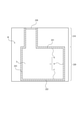
- the manhole M is an underground structure made of reinforced concrete.
- the manhole M includes a neck portion 210, a skeleton portion 220, and an iron lid 230.
- the skeleton portion 220 includes a ceiling portion 221, a floor portion 222, and a side wall portion 223.
- a neck portion 210 is connected to the ceiling portion 221 of the skeleton portion 220.
- a space portion S exists in the skeleton portion 220, and the space portion S is surrounded by an inner wall surface I.
- the inner wall surface I includes the ceiling surface R of the ceiling portion 221, the side wall surface H of the side wall portion 223, and the floor surface F of the floor portion 222.
- One end of the neck 210 is connected to the ceiling surface R of the skeleton 220, and the other end of the neck 210 is exposed to the ground.
- the skeleton 220 and the neck 210 are made of reinforced concrete.
- the humidifier 20 is a device that releases moisture in the space S of the manhole M to humidify the space S. As disclosed in Document 1 below, it is known that humidity in the environment is a factor that greatly contributes to the rate of progress of neutralization of concrete. Therefore, in the present embodiment, the humidity of the space S is controlled by the humidifier 20.
- the humidifier 20 is a steam type humidifier.
- the humidifier 20 is not limited to this, and may be an ultrasonic humidifier, a vaporization type humidifier, or the like.
- the humidifier 20 includes a heater, an evaporating dish, a fan, an openable / closable spout, a water supply tank, and a control unit.
- the control unit of the humidifier 20 controls the heater, the fan, and the spout.
- water is supplied to the evaporating dish from the water supply tank, and a heater provided on the bottom surface of the evaporating dish heats the water.
- the heated and evaporated water is discharged from the spout by a fan to humidify the space S.
- the water supply tank supplies water to the evaporating dish from above the evaporating dish.
- a water supply port provided with a water supply valve is provided at the bottom of the water supply tank, and when the water supply tank is installed, a push-in pin provided on the evaporating dish pushes up the water supply valve from below. In this way, the water supply valve is opened and water is supplied to the evaporating dish.
- the control unit of the humidifier 20 controls the operation of the entire humidifier 20 according to the instruction received from the control unit 11 of the humidity control device 10.
- the space thermo-hygrometer 30 is a device that measures the temperature and humidity of the space S of the manhole M.
- the space temperature / humidity meter 30 includes a temperature / humidity sensor, a control unit, a storage unit, and a communication unit.
- the temperature / humidity sensor detects the temperature and humidity of the space S, and stores the detected temperature and humidity in the storage unit as space temperature information and humidity information, respectively.
- the control unit transmits the space temperature information and the humidity information to the humidity control device 10 via the communication unit.
- the space temperature information and the humidity information may be transmitted at all times, or may be performed according to an instruction from the humidity adjusting device 10.
- the space thermo-hygrometer 30 is attached to the side wall surface H of the manhole M, but the position of the space thermo-hygrometer 30 is not limited to this.
- the space thermo-hygrometer 30 is placed on a support leg extending from the floor 222 toward the ceiling 221 so as to measure the temperature and humidity of the space S at a predetermined height from the floor F. It may be attached.
- the control unit of the space thermo-hygrometer 30 controls the operation of the entire space thermo-hygrometer 30 according to the instruction received from the humidity adjusting device 10.
- the inner wall surface thermometer 40 is a device that measures the temperature of the inner wall surface I of the manhole M.
- the inner wall surface thermometer 40 includes a temperature sensor, a storage unit, and a communication unit.
- the temperature sensor of the inner wall surface thermometer 40 detects the temperature of the inner wall surface I, and stores the detected temperature as the inner wall surface temperature information in the storage unit.
- the control unit transmits the inner wall surface temperature information to the humidity control device 10 via the communication unit. The transmission of the inner wall surface temperature information may be performed at all times, or may be performed according to an instruction from the humidity adjusting device 10.
- the inner wall surface thermometer 40 is attached to the ceiling surface R of the manhole M.
- the temperature sensor detects the temperature of the ceiling surface R and stores the detected temperature in the storage unit as the inner wall surface temperature information.
- the control unit of the inner wall surface thermometer 40 controls the operation of the entire inner wall surface thermometer 40 according to the instruction received from the humidity adjusting device 10.
- FIG. 3 is a block diagram showing the configuration of the system 1 including the humidity control device 10 according to the present embodiment.
- the control unit 11 of the humidity adjustment device 10 includes a critical humidity value calculation unit 111 and an operation determination unit 112.
- the control unit 11 acquires humidity information indicating the humidity of the space unit S of the manhole M and space temperature information indicating the temperature of the space unit S from the space unit thermo-hygrometer 30 via the communication unit 13.
- the control unit 11 further acquires the inner wall surface temperature information indicating the temperature of the inner wall surface I of the manhole M from the inner wall surface thermometer 40 via the communication unit 13.
- the inner wall surface temperature information indicates the temperature of the ceiling surface R.
- the control unit 11 stores the acquired humidity information, the space temperature information, and the inner wall surface temperature information in the storage unit 12.
- the critical humidity value calculation unit 111 calculates a critical humidity value in which dew condensation does not occur in the manhole M based on the space temperature information, the inner wall surface temperature information, and the above-mentioned humidity information.
- the operation determination unit 112 determines the operation of the humidifier 20 so that the humidity is maintained in the range of the reference humidity value or more and the critical humidity value or less.
- the control unit 11 transmits the determined operation instruction to the humidifier 20.
- the humidifier 20 receives an instruction and operates based on the instruction.
- the “reference humidity value” is a humidity value at which the progress of neutralization of the concrete constituting the manhole M is suppressed. As disclosed in Document 2 below, it has been clarified that the neutralization of concrete hardly progresses when the relative humidity is 90% or more. Therefore, in the present embodiment, the humidity is controlled so that the humidity of the space S of the manhole M is equal to or higher than the reference humidity value. In this embodiment, the reference humidity value is set to 90%. The reference humidity value is not limited to this, and may be freely set. Reference 2: Hisami Kasahara, 2 outsiders, "Progressive behavior of neutralization in reinforced concrete manholes for communication", Reiwa 1st year Japan Society of Civil Engineers National Convention 74th Annual Academic Lecture, V-352, 2019
- the "critical humidity value” is a value of the critical humidity at which dew condensation occurs on the inner wall surface I of the manhole M.
- the value of the critical humidity at which dew condensation occurs on the ceiling surface R of the manhole M is shown.
- Document 3 when the inside of the manhole M is continuously humidified, the moisture in the air exceeds the saturated water vapor pressure and becomes a liquid. A large amount of liquid water in the manhole M interferes with the work inside the manhole and corrodes the reinforcing bars exposed from the reinforced concrete of the manhole M as dew condensation, so it is preferable not to occur as much as possible.
- Reference 3 Hisami Kasahara, 2 outsiders, "Effect of temperature on the corrosion behavior of reinforcing bars due to dew condensation", 2018 Japan Society of Civil Engineers National Convention 73rd Annual Academic Lecture, VI-235, 2018
- the control unit 11 of the humidity control device 10 includes one or more processors.
- the "processor” is a general-purpose processor or a dedicated processor specialized for a specific process, but is not limited thereto. It may be configured by dedicated hardware, a general-purpose processor, or a processor specialized for a specific process.
- the control unit 11 executes processing related to the operation of the entire humidity control device 10 while controlling each part of the humidity control device 10.
- the control unit 11 includes a critical humidity value calculation unit 111 and an operation determination unit 112.
- One or more programs used for controlling the operation of the control unit 11 are stored in the storage unit 12, and the program is read by the control unit 11, so that the control unit 11 has the critical humidity value calculation unit 111 and the operation determination unit 112. Functions as.
- the control unit 11 controls the humidity of the space unit S of the manhole M, as will be described in detail below.
- the control is performed by transmitting the operation instruction determined by the operation determination unit 112 to the humidifier 20 via the communication unit 13.
- control unit 11 acquires the measured space temperature information, humidity information, and inner wall surface temperature information from the space temperature / hygrometer 30 and the inner wall surface thermometer 40 by receiving them via the communication unit 13. ..
- the control unit 11 may acquire the space temperature information, the humidity information, and the inner wall surface temperature information periodically or irregularly.
- the operation determination unit 112 compares the humidity included in the humidity information with the reference humidity value, and determines whether or not the humidity is less than the reference humidity value.
- the operation determination unit 112 determines the operation of the humidifier 20 so that the humidifier 20 performs a large amount of humidification.
- the operation determination unit 112 transmits an operation instruction to the humidifier 20 via the communication unit 13.
- "A large amount of humidification” specifically means to increase the amount of water released from the humidifier 20, or to lengthen the duration of the humidifying operation, and is freely defined by the function of the humidifier 20. It's okay.
- the critical humidity value calculation unit 111 calculates the critical humidity value with reference to the space temperature information and the inner wall surface temperature information.
- the critical humidity value calculation unit 111 first calculates the value of e based on the following equation (1).
- T is the temperature of the space portion S of the manhole M included in the space portion temperature information
- the unit is the temperature in degrees Celsius (° C.).
- the calculated e is the value of the saturated water vapor pressure when the temperature of the space S of the manhole M is T, and the unit is hPa.
- e is calculated using the equation (1), but other approximate equations may be used in addition to the equation (1).
- the critical humidity value calculation unit 111 calculates the value of a based on the following equation (2).
- a calculated in the formula (2) is a value of the saturated water vapor amount when the temperature of the space portion S of the manhole M is T, and the unit is m 3 / g.
- the critical humidity value calculation unit 111 calculates the value of e'based on the following equation (3).
- t is the temperature of the ceiling surface R of the manhole M included in the inner wall surface temperature information, and the unit is the temperature in degrees Celsius (° C.).
- the calculated e' is the value of the saturated water vapor pressure when the air in the manhole M hits the ceiling surface R and the temperature of the space S becomes t, and the unit is hPa.
- e' is calculated using the equation (3), but other approximate equations may be used in addition to the equation (3).
- the critical humidity value calculation unit 111 calculates the value of a'based on the following equation (4).
- A'calculated in the equation (4) is the value of the saturated water vapor amount when the air in the manhole M hits the ceiling surface R and the temperature of the space S becomes t, and the unit is m 3 / g. ..
- the critical humidity value calculation unit 111 calculates the critical humidity value based on the following equation (5).
- a' that is, the value of the amount of water vapor in which the air that has reached the temperature t in contact with the ceiling surface R of the manhole M begins to cause dew condensation
- the value of the saturated water vapor amount is the space of the manhole M. It is shown that the part S is equal to the amount of water vapor at a humidity of X% in an environment where the temperature is T.
- the X is calculated as a critical humidity value.
- the critical humidity value calculation unit 111 outputs information indicating the critical humidity value calculated in this way to the operation determination unit 112.
- the operation determination unit 112 determines whether or not the humidity included in the humidity information is less than the critical humidity value. When the operation determination unit 112 determines that the humidity is equal to or higher than the reference humidity value and is lower than the critical humidity value, the operation determination unit 112 determines the operation of the humidifier 20 so that the humidifier 20 performs a small amount of humidification. The operation determination unit 112 transmits an operation instruction to the humidifier 20 to perform a small amount of humidification via the communication unit 13. "A small amount of humidification” specifically means humidifying with the amount of water released from the humidifier 20 reduced, shortening the duration of the humidifying operation, and the like, and the function of the humidifier 20. May be determined by.
- the operation determination unit 112 determines the operation of the humidifier 20 so that the humidifier 20 stops humidification. do.
- the operation determination unit 112 transmits an operation instruction to the humidifier 20 to stop humidification via the communication unit 13.
- the storage unit 12 includes one or more memories, and may include, for example, a semiconductor memory, a magnetic memory, an optical memory, and the like. Each memory included in the storage unit 12 may function as, for example, a main storage device, an auxiliary storage device, or a cache memory.
- the storage unit 12 stores various information used for the operation of the humidity control device 10.
- the storage unit 12 stores the humidity information, the space temperature information, and the inner wall surface temperature information acquired by the control unit 11.
- the storage unit 12 also stores information indicating a reference humidity value.
- the communication unit 13 includes at least one communication interface.
- the communication interface is, for example, a LAN interface.
- the communication unit 13 receives the information used for the operation of the humidity control device 10 and transmits the information obtained by the operation of the humidity control device 10.
- the input unit 14 includes at least one input interface.
- the input interface is, for example, a physical key, a capacitive key, a pointing device, a touch screen integrated with a display, or a microphone.
- the input unit 14 accepts an operation for inputting information used for the operation of the humidity control device 10.
- the input unit 14 can directly receive input from the user such as humidity information, space temperature information, inner wall surface temperature information, information indicating a reference humidity value, or information indicating a critical humidity value.
- the output unit 15 includes at least one output interface.
- the output interface is, for example, a display or a speaker.
- the display is, for example, a liquid crystal display, an organic EL display, an inorganic EL display, or the like.
- the output unit 15 may be a touch panel, and in this case, the output unit 15 functions as an input unit 14 that displays various information to the user and accepts input by the user's operation.
- the humidity control device 10 may be a computer capable of executing program instructions.
- the computer stores a program describing the processing contents that realize each function of the humidity control device 10 in the storage unit of the computer, and the processor of the computer reads and executes this program. Some of these processing contents may be realized by hardware.
- the computer may be a general-purpose computer, a dedicated computer, a workstation, a PC (Personal Computer), an electronic notepad, or the like.
- the program instruction may be a program code, a code segment, or the like for executing a necessary task.
- the processor may be a CPU (Central Processing Unit), a GPU (Graphics Processing Unit), a DSP (Digital Signal Processor), or the like.
- this program may be recorded on a recording medium that can be read by a computer. Using such a recording medium, it is possible to install the program on the computer.
- the recording medium on which the program is recorded may be a non-transient recording medium.
- the non-transient recording medium is not particularly limited, but may be, for example, a recording medium such as a CD-ROM or a DVD-ROM.
- the program can also be provided by download over the network.
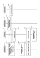
- FIG. 4 shows an example of the operation of the system 1.
- FIG. 5 is a flowchart showing an example of the operation of the control unit 11 of the humidity control device 10. In this example, it is assumed that the humidifier 20 is in operation.
- step S101 the control unit of the space thermo-hygrometer 30 refers to the storage unit and transmits the space temperature information and the humidity information to the humidity adjusting device 10 via the communication unit.
- step S102 the control unit of the inner wall surface thermometer 40 refers to the storage unit and transmits the inner wall surface temperature information to the humidity control device 10 via the communication unit.
- step S103 the control unit 11 of the humidity control device 10 receives the space temperature information, the humidity information, and the inner wall surface temperature information from the space temperature / humidity meter 30 and the inner wall surface thermometer 40 via the communication unit 13. Get by doing.
- the control unit 11 stores the acquired space temperature information, humidity information, and inner wall surface temperature information in the storage unit 12.
- step S104 the control unit 11 determines the operation instructed to the humidifier 20.
- FIG. 5 shows a specific processing flow of determining the operation in step S104.
- step S201 the operation determination unit 112 reads out the humidity information and the reference humidity value stored in the storage unit 12. The operation determination unit 112 compares the humidity included in the humidity information with the reference humidity value, and determines whether or not the humidity is less than the reference humidity value.
- the operation determination unit 112 determines the operation of the humidifier 20 so that the humidifier 20 performs a large amount of humidification in step S202, and the process of determining the operation ends. If the humidity is equal to or higher than the reference humidity value, the process of determining the operation proceeds to step S203. In this example, the humidity is 95 percent and the reference humidity value is 90 percent. Since the humidity is equal to or higher than the reference humidity value, the process of determining the operation proceeds to step S203.
- step S203 the critical humidity value calculation unit 111 calculates the critical humidity value by referring to the space temperature information, the inner wall surface temperature information, and the humidity information.
- the critical humidity value calculation unit 111 outputs information indicating the calculated critical humidity value to the operation determination unit 112.
- step S204 the operation determination unit 112 compares the humidity with the critical humidity value, and determines whether or not the humidity is less than the critical humidity value.
- the operation determination unit 112 determines the operation of the humidifier 20 so that the humidifier 20 performs a small amount of humidification in step S205, and the process of determining the operation ends.
- the operation determination unit 112 determines the operation of the humidifier 20 so that the humidifier 20 stops humidification in step S206.
- the humidity is 95 percent and the critical humidity value is 94 percent. Since the humidity is equal to or higher than the critical humidity value, the operation determination unit 112 determines the operation to stop the humidification in step S206. In this way, the process of determining the operation instructed to the humidifier 20 is completed.
- step S105 the operation determination unit 112 transmits an operation instruction to the humidifier 20 to execute the process of the determined operation via the communication unit 13. In this way, the humidifier 20 is controlled.
- the control unit 11 since the determined operation is the operation of stopping the humidification, the control unit 11 transmits an instruction of the operation of stopping the humidification to the humidifier 20 via the communication unit 13.
- step S106 the control unit of the humidifier 20 receives an operation instruction from the humidity control device 10 via the communication unit.
- the control unit of the humidifier 20 receives an instruction of an operation to stop humidification.
- step S107 the humidifier 20 operates according to the instruction from the humidity control device 10. Specifically, the control unit of the humidifier 20 controls each unit of the humidifier 20 so as to operate according to the received instruction. In this example, the heater, fan, and spout of the humidifier 20 are controlled so as to perform an operation of stopping humidification.
- the humidity of the space S of the manhole M is controlled by the above steps S101 to S107.
- the humidity adjusting device 10 includes a control unit 11 that acquires humidity information indicating the humidity of the space S of the manhole M and controls the humidity based on the humidity information.
- the humidity in the manhole M made of reinforced concrete can be controlled.
- the humidity of the space portion S of the manhole M to an appropriate value, it is possible to prevent the progress of neutralization of the concrete constituting the manhole M.
- the control unit 11 has the space temperature information indicating the temperature of the space portion S of the manhole M and the inner wall surface temperature indicating the temperature of the inner wall surface I of the manhole M. The result of further acquiring the information, calculating the critical humidity value at which dew does not occur in the manhole M based on the space temperature information, the inner wall surface temperature information, and the humidity information, and comparing the critical humidity value and the humidity. Humidity is controlled based on.
- the critical humidity value is calculated based on the temperature and humidity of the space portion S of the manhole M and the temperature of the ceiling surface R included in the inner wall surface I. Since the humidity can be controlled by comparing the critical humidity value with the humidity, it is possible to prevent the occurrence of dew condensation due to excessive humidification in the manhole M.
- the humidity control device 10 further includes a communication unit 13 that communicates with the humidifier 20 that humidifies the inside of the manhole M.
- the control unit 11 of the humidity adjusting device 10 determines the operation of the humidifier 20 so that the humidity is maintained in the range of the reference humidity value or more and less than the critical humidity value, and the determined operation is performed by the humidifier 20 via the communication unit 13. Send to.
- the humidity in the manhole M can be controlled more accurately by controlling the operation of the humidifier 20.
- the humidity in the manhole M can be maintained at a humidity at which the progress of neutralization of concrete is suppressed and dew condensation does not occur.
- FIG. 6 shows an outline of the system 2 according to the present embodiment.
- Reference to FIG. 6 is different from the first embodiment in that the water supply device 50 is provided instead of the humidifier 20.
- the humidity control device 10, the water supply device 50, the space thermometer 30, and the inner wall surface thermometer 40 are communicably connected by wire or wirelessly.
- the communication method for transmitting and receiving information between the humidity control device 10, the water supply device 50, the space thermometer 30, and the inner wall surface thermometer 40 is not particularly limited.
- the humidity control device 10 may be installed outside the manhole M.
- the water supply device 50 is a device that stores water in a liquid state so that the water evaporates in the space S of the manhole M.
- the water supply device 50 includes a water supply container 51, an openable / closable lid 52, a water supply tank 53, a water supply passage 54, a water level sensor 55, a water supply pump, a motor, a control unit, a storage unit, and a communication unit.
- the control unit of the water supply device 50 controls the lid 52, the water supply pump, and the motor.
- the water supply tank 53 is provided on the ground, but may be provided in the manhole M.
- water is sucked up from the water supply tank 53 by the water supply pump and sent to the water supply passage 54. Water exits from the end of the water supply passage 54 to the water supply container 51.
- the manhole M is humidified by the evaporation of water from the water supply container 51.
- the water supply pump is driven by a motor, and the motor is controlled by the control unit of the water supply device 50.
- the water level sensor 55 detects the water level in the water supply container 51.
- the control unit of the water supply device 50 acquires the water level detected by the water level sensor 55, calculates the amount of water in the water supply container 51, and stores it in the storage unit as water amount information. The amount of water can be calculated based on the volume of the water supply container 51 stored in the storage unit in advance.
- the control unit of the water supply device 50 transmits the water amount information to the humidity control device 10 via the communication unit.
- the water amount information may be transmitted at all times, or may be performed according to an instruction from the humidity control device 10. By opening and closing the lid 52, the amount of water evaporated from the water supply device 50 is adjusted.
- the control unit of the water supply device 50 controls the operation of the entire water supply device 50 according to the instruction received from the control unit 11 of the humidity control device 10.
- FIG. 7 is a block diagram showing the configuration of the system 2 according to the present embodiment.
- the humidity control device 10 communicates with the water supply device 50 instead of the humidifier 20, and the water supply. It differs from the first embodiment in that information is transmitted from the device 50 to the humidity control device 10 and that the control unit 11 further includes a required water amount calculation unit 113.
- the control unit 11 of the humidity adjusting device 10 acquires humidity information, space temperature information, and inner wall surface temperature information, as in the first embodiment.
- the control unit 11 further acquires water amount information indicating the amount of water in the water supply device 50 from the water supply device 50.
- the control unit 11 stores the acquired humidity information, space temperature information, inner wall surface temperature information, and water amount information in the storage unit 12.
- the critical humidity value calculation unit 111 calculates the critical humidity value in the same manner as in the first embodiment.
- the required water amount calculation unit 113 calculates the required water amount of the water supply device 50 based on the space temperature information, the inner wall surface temperature information, the humidity information, and the information indicating the critical humidity value.
- the operation determination unit 112 determines the operation of the water supply device 50 so that the humidity is maintained in the range of the reference humidity value or more and the critical humidity value or less. Specifically, the operation determination unit 112 determines the operation of the water supply device 50 based on the result of comparing the required amount of water with the amount of water in the water supply device 50.
- the control unit 11 transmits the determined operation instruction to the water supply device 50.
- the water supply device 50 receives an instruction and operates based on the instruction.
- the "required amount of water” is the amount of water that is insufficient to make the humidity of the space S of the manhole M a critical humidity value. Specifically, the required amount of water is calculated as the amount of water vapor as shown below.
- the control unit 11 controls the humidity of the space unit S of the manhole M, as will be described in detail below.
- the control is performed by transmitting the operation instruction determined by the operation determination unit 112 to the water supply device 50 via the communication unit 13.
- the control unit 11 acquires the space temperature information, the humidity information, and the inner wall surface temperature information.
- the control unit 11 further acquires water amount information from the water supply device 50 by receiving it via the communication unit 13.
- the control unit 11 may acquire the space temperature information, the humidity information, the inner wall surface temperature information, and the water amount information periodically or irregularly.
- the operation determination unit 112 compares the humidity included in the humidity information with the reference humidity value, and determines whether or not the humidity is less than the reference humidity value, as in the first embodiment.
- the operation determination unit 112 determines the operation of the water supply device 50 so that the water supply device 50 takes in water.
- the operation determination unit 112 transmits an operation instruction to the water supply device 50 via the communication unit 13. "Taking in water” means, in the present embodiment, that the control unit of the water supply device 50 controls the motor or the lid 52 to add water to the water supply container 51 or prevent evaporation. It may be freely determined by 50 functions.
- the critical humidity value calculation unit 111 calculates the critical humidity value by the same method as in the first embodiment.
- the critical humidity value calculation unit 111 outputs information indicating the calculated critical humidity value to the required water amount calculation unit 113.
- the required water amount calculation unit 113 calculates the required water amount to be supplied to the water supply device 50 by referring to the humidity information, the space temperature information, the inner wall surface temperature information, and the information indicating the critical humidity value.
- the required water amount calculation unit 113 first calculates the value of A based on the following equation (6).
- a is a value of the saturated water vapor amount when the temperature of the space portion S of the manhole M is T, and the calculation method is the same as the method shown in the first embodiment, so the description thereof will be omitted. ..
- V is the space volume in the manhole, and the unit is m 3 .
- RH is the humidity of the space S, and the unit is percentage.
- the calculated A is the amount of water vapor existing in the space S of the manhole M, and the unit is g.
- the required water amount calculation unit 113 calculates the value of B based on the following formula (7).
- the term a' ⁇ V indicates the amount of water vapor existing in the space S when the humidity of the space S of the manhole M is the critical humidity value.
- the calculated B is the amount of water vapor insufficient to make the humidity of the space S of the manhole M a critical humidity value, and the unit is g.
- the required water amount calculation unit 113 outputs the water vapor amount calculated in this way to the operation determination unit 112 as the required water amount.
- the humidity in the space S approaches the critical humidity value. In this way, by calculating and using the required amount of water, the humidity of the space S can be maintained within the range of the reference humidity value or more and less than the critical humidity value.
- the operation determination unit 112 determines whether or not the amount of water included in the water amount information is equal to or greater than the required amount of water.
- the water supply device 50 stops the water supply device 50 from taking in water into the water supply container 51. Determines the behavior of.
- the operation determination unit 112 transmits an operation instruction to the water supply device 50 via the communication unit 13.
- the operation determination unit 112 determines the operation of the water supply device 50 so that the water supply device 50 takes in water into the water supply container 51. do.
- the operation determination unit 112 transmits an operation instruction to the water supply device 50 via the communication unit 13.
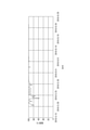
- FIG. 8 shows the result of controlling the humidity of the space portion S of the manhole M by using the water supply device 50 according to the present embodiment.
- FIG. 8 is a graph showing changes in the humidity of the space S of the manhole M.
- the vertical axis is the humidity of the space S of the manhole M
- the horizontal axis is the date when the humidity is measured.
- the humidity value in the manhole M changes up and down for about 10 days from May 20, 2019 when the water supply device 50 is arranged. It is considered that such a behavior was exhibited as a result of the change in the saturated water vapor amount with the change in the temperature in the manhole M.
- the humidity of the space S of the manhole M is maintained at a high humidity of almost 100%. It is considered that this is due to the vaporization action of water from the installed water supply device 50. As shown in FIG. 8, it can be seen that the humidity of the space S of the manhole M can be effectively controlled by using the water supply device 50.
- FIG. 9 shows an example of the operation of the system 2.
- FIG. 10 is a flowchart showing an example of the operation of the control unit 11 of the humidity control device 10 according to the present embodiment. In this example, it is assumed that water is supplied to the water supply device 50.
- steps S301 to S302 in FIG. 8 are the same as steps S101 to S102 in FIG. 4 of the first embodiment, the description thereof will be omitted.
- step S303 the control unit of the water supply device 50 refers to the storage unit, and transmits water amount information indicating the amount of water in the water supply device 50 to the humidity control device 10 via the communication unit.
- step S304 the control unit 11 of the humidity control device 10 obtains the space temperature information, the humidity information, the inner wall surface temperature information, and the water amount information via the communication unit 13, the space temperature / humidity meter 30, and the inner wall surface thermometer. Obtained by receiving from 40 and the water supply device 50.
- the control unit 11 stores the acquired space temperature information, humidity information, inner wall surface temperature information, and water amount information in the storage unit 12.
- step S305 the control unit 11 determines the operation instructed to the water supply device 50.
- FIG. 10 shows a specific processing flow of determining the operation in step S305.
- step S401 the operation determination unit 112 reads out the humidity information and the reference humidity value stored in the storage unit 12. The operation determination unit 112 compares the humidity included in the humidity information with the reference humidity value, and determines whether or not the humidity is less than the reference humidity value.
- the operation determination unit 112 determines the operation of the water supply device 50 so that the water supply device 50 takes in water in step S402, and the process of determining the operation ends. If the humidity is equal to or higher than the reference humidity value, the process of determining the operation proceeds to step S403. In this example, the humidity is 95 percent and the reference humidity value is 90 percent. Since the humidity is equal to or higher than the reference humidity value, the process of determining the operation proceeds to step S403.
- step S403 the critical humidity value calculation unit 111 calculates the critical humidity value by referring to the space temperature information, the inner wall surface temperature information, and the humidity information.
- the critical humidity value calculation unit 111 outputs information indicating the calculated critical humidity value to the required water amount calculation unit 113.
- step S404 the required water amount calculation unit 113 calculates the required water amount to be supplied to the water supply device 50 by referring to the humidity information, the space temperature information, the inner wall surface temperature information, and the information indicating the critical humidity value.
- the required water amount calculation unit 113 outputs information indicating the calculated required water amount to the operation determination unit 112.
- step S405 the operation determination unit 112 compares the amount of water with the required amount of water, and determines whether or not the amount of water is equal to or greater than the required amount of water.
- the operation determination unit 112 determines the operation of the water supply device 50 so that the water supply device 50 stops taking in water in step S406, and the process of determining the operation ends. ..
- the operation determination unit 112 determines the operation of the water supply device 50 so that the water supply device 50 takes in water in step S402. In this example, the amount of water is less than the required amount of water. Therefore, the operation determination unit 112 determines the operation of the water supply device 50 so that the water supply device 50 takes in water in step S402. In this way, the process of determining the operation instructed to the water supply device 50 is completed.
- step S306 the operation determination unit 112 transmits an operation instruction to the water supply device 50 to execute the processing of the determined operation via the communication unit 13. In this way, the water supply device 50 is controlled.
- the control unit 11 since the determined operation is the operation of taking in water, the control unit 11 transmits an instruction of the operation of taking in water to the water supply device 50 via the communication unit 13.
- step S307 the control unit of the water supply device 50 receives an operation instruction from the humidity control device 10 via the communication unit.
- the control unit of the water supply device 50 receives an instruction of an operation of taking in water.
- step S308 the water supply device 50 operates according to the instruction from the humidity control device 10. Specifically, the control unit of the water supply device 50 controls each unit of the water supply device 50 so as to operate according to the received instruction. In this example, the motor of the water supply device 50 is controlled so as to perform an operation of taking in water.
- the humidity of the space S of the manhole M is controlled by the above steps S301 to S308.
- the humidity control device 10 further includes a communication unit 13 that communicates with the water supply device 50 installed in the manhole M.
- the control unit 11 of the humidity adjusting device 10 determines the operation of the water supply device 50 so that the humidity is maintained in the range of the reference humidity value or more and less than the critical humidity value, and the determined operation is supplied with water via the communication unit 13. It is transmitted to the device 50.
- the humidity in the manhole M can be controlled more accurately by controlling the operation of the water supply device 50.
- the humidity in the manhole M can be maintained at a humidity at which the progress of neutralization of concrete is suppressed and dew condensation does not occur.
- the control unit 11 acquires water amount information indicating the amount of water in the water supply device 50, and obtains space temperature information, inner wall surface temperature information, and humidity information.
- the required water amount of the water supply device 50 is calculated based on the information indicating the critical humidity value, and the operation of the water supply device 50 is determined based on the result of comparing the required water amount with the water amount in the water supply device 50. Then, the determined operation is transmitted to the water supply device 50 via the communication unit 13.
- the required water amount of the water supply device 50 is calculated more accurately based on the temperature and humidity of the space portion S of the manhole M and the temperature of the ceiling surface R included in the inner wall surface I. Since the water supply device 50 can control the operation of taking water into the water supply container 51 based on the calculated required water amount, the inside of the manhole M can always be kept at an appropriate humidity.
- control unit 11 of the humidity control device 10 may further include an airtightness determination unit 114.
- the airtightness determination unit 114 determines whether or not the manhole M has airtightness, as will be described in detail below.
- the airtightness determination unit 114 reads out the humidity information stored in the storage unit 12 and the hygroscopicity information previously stored in the storage unit 12 indicating the hygroscopicity of the concrete constituting the manhole M.
- "Hygroscopic information” includes a humidity decrease reference value, a humidity change reference tendency, and a humidity decrease duration reference value.
- the hygroscopicity information is set according to the humidity control property of the concrete constituting the manhole M.
- the humidity control property of concrete means that when concrete is dry compared to the surrounding environment, it absorbs moisture, and when it is moist, it releases moisture. Refers to the performance of performing.
- the "humidity decrease standard value” is a value indicating the standard of the humidity decrease in the manhole M.
- the amount of decrease in humidity in the sealed manhole M at a certain time is measured in advance, and the amount of decrease is used as the reference value for the amount of humidity decrease. It is known that the rate of moisture absorption by concrete is slow, and the amount of decrease in humidity in the manhole M composed of concrete is relatively small. Therefore, the amount of decrease in humidity in the sealed manhole M can be measured in advance and used as a reference value.
- “Humidity change standard tendency” indicates the tendency of the humidity in the manhole M to change with time.
- the tendency of humidity change in a certain time is measured in advance, and this tendency is used as the humidity change reference tendency.
- the size and shape of manholes are defined by standards, and the tendency of humidity change due to the hygroscopic function of concrete is the same for manholes of the same size and shape. Therefore, the tendency of humidity change in manholes of the same size and shape can be grasped in advance and used as a reference for judging other manholes.
- the “duration reference value” is a value indicating the duration of the decrease in humidity in the manhole M.
- the time for which the humidity continues to decrease is measured in advance, and this time is used as the duration reference value.
- the decrease in humidity due to moisture absorption of concrete stops after a certain period of time as long as the inside of the manhole is kept in a high humidity environment, but in a manhole with low airtightness, the decrease in humidity does not stop or stops temporarily. Also resumes. Therefore, the duration of the decrease in humidity can be measured in advance and used as a reference value.
- the airtightness determination unit 114 determines whether or not the manhole M is airtight by comparing the humidity included in the humidity information with the humidity change reference tendency, the humidity decrease amount reference value, or the duration reference value. conduct. For example, the airtightness determination unit 114 determines that the manhole M is airtight when the tendency of the humidity change matches the humidity change reference tendency. For example, the airtightness determination unit 114 determines that the manhole M is airtight when the amount of decrease in humidity is less than the reference value for the amount of decrease in humidity. For example, the airtightness determination unit 114 determines that the manhole M is airtight when the duration of the decrease in humidity is less than the duration reference value. The airtightness determination unit 114 may make a judgment on the airtightness by using only one of the humidity change reference tendency, the humidity decrease amount reference value, or the duration reference value, or make a judgment by using a plurality of them. You may go.
- the control unit 11 notifies the user of the result of the determination by the airtightness determination unit 114 via the output unit 15. In this way, the user can grasp the airtightness of the manhole M.
- the control unit 11 may transmit the determined result to the terminal device of the user who inspects the manhole M via the communication unit 13.
- the operation determination unit 112 may determine the operation performed by the humidifier 20 or the water supply device 50 according to the result determined by the airtightness determination unit 114. For example, when the airtightness determination unit 114 determines that the manhole M is not airtight, the operation determination unit 112 may determine the operation of the humidifier 20 so that the humidifier 20 performs a large amount of humidification. For example, when the airtightness determination unit 114 determines that the manhole M is not airtight, the operation determination unit 112 may determine the operation of the water supply device 50 so that the water supply device 50 takes in water.
- the operation instruction determined by the operation determination unit 112 may be transmitted to the humidifier 20 or the water supply device 50 via the communication unit 13, and the humidifier 20 or the water supply device 50 may operate according to the instruction.
- the control unit 11 determines whether or not the manhole M has a hermeticity based on the humidity information.
- control unit 11 of the humidity control device 10 determines the airtightness based on the humidity control property of the concrete constituting the manhole M.
- the humidity control device 10 may further include a dehumidification device.
- the humidity control device 10 controls the dehumidifier in addition to controlling the operation of the humidifier 20 or the water supply device 50.
- the humidity in the manhole M can be adjusted more quickly and accurately by using the dehumidifying function of the dehumidifying device.
- the dehumidifying device quickly reduces the humidity of the space S and prevents the humidity from reaching the critical humidity value. be able to.
- the control unit 11 of the humidity control device 10 estimates the temperature of the ceiling surface R of the manhole M from the temperature included in the space temperature information instead of acquiring it from the inner wall surface thermometer 40. May be good.
- the control unit 11 may estimate the temperature of the ceiling surface R by analyzing the temperature included in the space temperature information and the depth of the manhole M previously stored in the storage unit 12 as parameters. Details of the method of measuring the temperature of the ceiling surface R by analyzing the temperature of the space portion S of the manhole M and the depth of the manhole M as parameters are disclosed in, for example, Document 7 below, and thus the description thereof is omitted. do.
- control unit 11 can acquire the temperature of the ceiling surface R without installing the inner wall surface thermometer 40 in the manhole M, the humidity in the manhole M can be controlled with a simpler configuration.
- the control unit 11 of the humidity control device 10 may acquire the temperature of the space unit S of the manhole M from the optical fiber by using a sensing technique instead of acquiring the temperature from the space unit thermo-hygrometer 30. good.
- the optical fiber is included in the communication cable installed in the manhole M. Since the details of the optical fiber sensing technique are disclosed in, for example, the following Document 8, the description thereof will be omitted.
- Reference 8 Tokuro Yamaguchi, 1 person outside "Distributed Optical Fiber Temperature Sensing", OKI Technical Review, No. 203, Vol. 84, No. 2, 2017
- control unit 11 can acquire the temperature of the space unit S without using the space temperature / hygrometer 30 in the manhole M, the humidity in the manhole M can be controlled with a simpler configuration. ..
- the humidity control device 10 is a moisture absorbing / releasing material (humidity control) having a moisture absorbing / releasing property in place of the humidifier 20 and the water supply device 50, or in addition to the humidifier 20 and the water supply device 50. Material) may be provided.
- the moisture absorbing / releasing material may be installed, for example, along the entire inner wall surface I of the manhole M.
- the humidity in the manhole M can be controlled by a simpler configuration.
Landscapes
- Engineering & Computer Science (AREA)
- General Engineering & Computer Science (AREA)
- Chemical & Material Sciences (AREA)
- Combustion & Propulsion (AREA)
- Mechanical Engineering (AREA)
- Human Computer Interaction (AREA)
- Life Sciences & Earth Sciences (AREA)
- Hydrology & Water Resources (AREA)
- Public Health (AREA)
- Water Supply & Treatment (AREA)
- Health & Medical Sciences (AREA)
- Air Conditioning Control Device (AREA)
- Underground Structures, Protecting, Testing And Restoring Foundations (AREA)
Abstract
本開示に係る湿度調整装置(10)は、マンホールの空間部の湿度を示す湿度情報を取得し、該湿度情報に基づいて前記湿度を制御する制御部(11)を備える。
Description
本開示は、湿度調整装置及び湿度調整方法に関する。
高い強度を有する鉄筋コンクリートは建物等の構造物に多く用いられている。近年、鉄筋コンクリートの劣化現象が社会問題となっている。該劣化現象の一つに中性化がある。中性化は、大気中の二酸化炭素によって打設時にアルカリ性であったコンクリートが徐々に中性となる現象である。中性化現象は空気と接しているコンクリートの表面から進行する。鉄筋コンクリート内部の鉄筋は、アルカリ性環境下では不働態を形成するため腐食は進行しないが、中性環境では腐食が進行する。中性化によって内部の鉄筋が腐食し減肉することで、鉄筋コンクリートの強度が低下する。中性化の抑制方法として、例えば特許文献1は、コンクリートの配合を工夫し、中性化に強い材料とする方法を開示している。また、特許文献2では、コンクリート表面に処理を施し、二酸化炭素の侵入を防止する方法を開示している。
しかしながら、コンクリートの配合を変える抑制方法はコストが高くなりがちであり、また、すでに打設済みの鉄筋コンクリートには使用できない。表面処理を施す方法については、人体への影響の懸念や、景観上望ましくない場合がある。また、風化等により表面処理が剥がれ落ち、効果がなくなることがある。このように、コンクリート配合の変更または表面処理を施すことは効果的でない場合がある。そこで、コンクリート配合を変更する方法または表面処理を施す方法を用いずに、コンクリートが存在する環境を変化させることによりコンクリートの中性化を抑制する方法が望まれていた。中でも、環境中の湿度がコンクリートの中性化進行速度に大きく寄与する要因であること、および、湿度の制御をすることは特に閉空間に存在する鉄筋コンクリートに対して効果的であることから、鉄筋コンクリート製のマンホールが存在する環境の湿度を制御できる湿度調整装置が望まれていた。
このような事情に鑑みてなされた本開示の目的は、鉄筋コンクリート製のマンホール内の湿度を制御できる湿度調整装置及び湿度調整方法を提供することを目的とする。
上述の課題を解決するため、本開示に係る湿度調整装置は、マンホールの空間部の湿度を示す湿度情報を取得し、該湿度情報に基づいて前記湿度を制御する制御部を備える。
また、本開示に係る湿度調整方法は、マンホールの空間部の湿度を示す湿度情報を取得するステップと、該湿度情報に基づいて前記湿度を制御するステップと、を含む。
本開示によれば、鉄筋コンクリート製のマンホール内の湿度を制御することができる。
以下、本開示の実施形態について適宜図面を参照しながら説明する。以下に説明する実施形態は本開示の構成の例であり、本開示は、以下の実施形態に制限されるものではない。
(第1実施形態)
図1を参照して、本開示の第1実施形態に係るシステム1の概要を説明する。図1に示すように、システム1は、マンホールM内に、湿度調整装置10と、加湿器20と、空間部温湿度計30と、内壁面温度計40とを備える。湿度調整装置10は、制御部11と、記憶部12と、通信部13と、入力部14と、出力部15とを備える。湿度調整装置10と、加湿器20、空間部温湿度計30、および内壁面温度計40とは、有線または無線により通信可能に接続される。湿度調整装置10と、加湿器20、空間部温湿度計30、および内壁面温度計40との間で情報を送受信するための通信方法は、特に限定されない。湿度調整装置10は、マンホールMの外に設置されてもよい。
図1を参照して、本開示の第1実施形態に係るシステム1の概要を説明する。図1に示すように、システム1は、マンホールM内に、湿度調整装置10と、加湿器20と、空間部温湿度計30と、内壁面温度計40とを備える。湿度調整装置10は、制御部11と、記憶部12と、通信部13と、入力部14と、出力部15とを備える。湿度調整装置10と、加湿器20、空間部温湿度計30、および内壁面温度計40とは、有線または無線により通信可能に接続される。湿度調整装置10と、加湿器20、空間部温湿度計30、および内壁面温度計40との間で情報を送受信するための通信方法は、特に限定されない。湿度調整装置10は、マンホールMの外に設置されてもよい。
ここで、マンホールMの構成について、図2を参照して簡単に説明する。マンホールMは鉄筋コンクリート製の地下構造物である。マンホールMは、首部210と、躯体部220と、鉄蓋230とを備える。躯体部220は、天井部221と、床部222と、側壁部223とを備える。躯体部220の天井部221には、首部210が連結される。躯体部220内には空間部Sが存在し、空間部Sは内壁面Iで囲まれている。内壁面Iは、天井部221の天井面R、側壁部223の側壁面H、床部222の床面Fを含む。首部210の一端は、躯体部220の天井面Rと連結され、首部210の他端は地面に露出する。躯体部220および首部210は鉄筋コンクリートで製造される。
図1に戻り、加湿器20、空間部温湿度計30および内壁面温度計40について説明する。
加湿器20は、マンホールMの空間部S内において水分を放出し、空間部Sを加湿する機器である。以下の文献1に開示されている通り、環境中の湿度はコンクリートの中性化進行速度に大きく寄与する要因であることがわかっている。したがって本実施形態では加湿器20により空間部Sの湿度を制御する。
文献1:白川敏夫、外2名、「コンクリートの中性化と湿度の関係に関する研究」、コンクリート工学年次論文報告書、Vol.18、No.1、1996年
文献1:白川敏夫、外2名、「コンクリートの中性化と湿度の関係に関する研究」、コンクリート工学年次論文報告書、Vol.18、No.1、1996年
本実施形態では、加湿器20は、スチーム式加湿器である。加湿器20はこれに限られず、超音波式加湿器または気化式加湿器等であってもよい。加湿器20は、ヒーター、蒸発皿、ファン、開閉可能な噴出口、給水タンクおよび制御部を備える。加湿器20の制御部は、ヒーター、ファンおよび噴出口を制御する。加湿器20において、給水タンクから水が蒸発皿に供給され、蒸発皿の底面に設けられたヒーターが水を加熱する。加熱され蒸発した水がファンによって噴出口から外に出され、空間部Sを加湿する。噴出口が開閉することで、加湿器20からの水分の放出量が調整される。給水タンクは蒸発皿の上方から蒸発皿に水を供給する。給水タンクの底部には給水弁を備える給水口が設けられ、給水タンクを設置すると、蒸発皿に設けられた押し込みピンが給水弁を下から押し上げる。このようにして給水弁が開いた状態となり、蒸発皿に水が供給される。加湿器20の制御部は、湿度調整装置10の制御部11から受信した指示に応じて加湿器20全体の動作を制御する。
空間部温湿度計30は、マンホールMの空間部Sの温度および湿度を測定する機器である。空間部温湿度計30は、温湿度センサ、制御部、記憶部および通信部を備える。温湿度センサは空間部Sの温度および湿度を検出し、検出した温度および湿度をそれぞれ空間部温度情報および湿度情報として記憶部に格納する。制御部は空間部温度情報および湿度情報を、通信部を介して、湿度調整装置10に送信する。空間部温度情報および湿度情報の送信は常時行われてもよいし、湿度調整装置10からの指示に応じて行ってもよい。本実施形態では、空間部温湿度計30はマンホールMの側壁面Hに取り付けられるが、空間部温湿度計30の位置はこれに限られない。例えば、空間部温湿度計30は、床面Fから所定の高さの位置で空間部Sの温度および湿度を測定するよう、床部222から天井部221に向かって延在する支持脚上に取り付けられてもよい。空間部温湿度計30の制御部は、湿度調整装置10から受信した指示に応じて空間部温湿度計30全体の動作を制御する。
内壁面温度計40は、マンホールMの内壁面Iの温度を測定する機器である。内壁面温度計40は、温度センサ、記憶部および通信部を備える。内壁面温度計40の温度センサは内壁面Iの温度を検出し、検出した温度を内壁面温度情報として記憶部に格納する。制御部は内壁面温度情報を、通信部を介して、湿度調整装置10に送信する。内壁面温度情報の送信は常時行われてもよいし、湿度調整装置10からの指示に応じて行ってもよい。本実施形態では、内壁面温度計40はマンホールMの天井面Rに取り付けられる。温度センサは天井面Rの温度を検出し、検出した温度を内壁面温度情報として記憶部に格納する。内壁面温度計40の制御部は、湿度調整装置10から受信した指示に応じて内壁面温度計40全体の動作を制御する。
図3は本実施形態に係る湿度調整装置10を含むシステム1の構成を示すブロック図である。湿度調整装置10の制御部11は、臨界湿度値算出部111と、動作決定部112とを備える。制御部11は、マンホールMの空間部Sの湿度を示す湿度情報と、空間部Sの温度を示す空間部温度情報とを、空間部温湿度計30から通信部13を介して取得する。制御部11は、マンホールMの内壁面Iの温度を示す内壁面温度情報を、内壁面温度計40からさらに通信部13を介して取得する。具体的には、当該内壁面温度情報は天井面Rの温度を示す。制御部11は、取得した湿度情報、空間部温度情報および内壁面温度情報を記憶部12に格納する。臨界湿度値算出部111は、該空間部温度情報と、該内壁面温度情報と、上述した湿度情報とに基づいてマンホールM内において結露が発生しない臨界湿度値を算出する。動作決定部112は、湿度が基準湿度値以上且つ臨界湿度値未満の範囲で保たれるよう加湿器20の動作を決定する。制御部11は、決定された動作の指示を加湿器20に送信する。加湿器20は指示を受信し、指示に基づいて動作を行う。
「基準湿度値」は、マンホールMを構成するコンクリートの中性化の進行が抑制される湿度の値である。以下の文献2に開示されている通り、相対湿度で90パーセント以上であると、コンクリートの中性化はほぼ進行しないことが明らかになっている。よって本実施形態では、マンホールMの空間部Sの湿度が基準湿度値以上であるよう当該湿度が制御される。本実施形態では、基準湿度値は90パーセントと設定する。基準湿度値はこれに限られず、自由に設定されてよい。
文献2:笠原久稔、外2名、「通信用鉄筋コンクリートマンホールにおける中性化の進行挙動」、令和元年度土木学会全国大会第74回年次学術講演会、V-352、2019年
文献2:笠原久稔、外2名、「通信用鉄筋コンクリートマンホールにおける中性化の進行挙動」、令和元年度土木学会全国大会第74回年次学術講演会、V-352、2019年
「臨界湿度値」は、マンホールMの内壁面Iに結露が発生する臨界湿度の値である。本実施形態では、具体的にはマンホールMの天井面Rに結露が発生する臨界湿度の値を示す。以下の文献3に開示されている通り、マンホールM内を加湿し続けると空気中の水分が飽和水蒸気圧を超えて液体となる。マンホールM中の多量の液状水はマンホール内作業に支障を来す他、結露としてマンホールMの鉄筋コンクリートから露出した鉄筋を腐食させるため、可能な限り生じないほうが好ましい。
文献3:笠原久稔、外2名、「結露による鉄筋の腐食挙動に及ぼす温度の影響」、平成30年度土木学会全国大会第73回年次学術講演会、VI-235、2018年
文献3:笠原久稔、外2名、「結露による鉄筋の腐食挙動に及ぼす温度の影響」、平成30年度土木学会全国大会第73回年次学術講演会、VI-235、2018年
また、以下の文献4に、多くのマンホールMでは、天井部221の温度が内部の空気よりも低くなることを原因として湿度が100パーセント以下でも結露が発生することが開示されている。よって本実施形態では、マンホールMの空間部Sの湿度が臨界湿度値未満であるよう当該湿度が制御される。
文献4:藤本憲宏、外2名、「通信用マンホールにおける結露発生機構」、平成30年度土木学会全国大会第73回年次学術講演会、V-395、2018年
文献4:藤本憲宏、外2名、「通信用マンホールにおける結露発生機構」、平成30年度土木学会全国大会第73回年次学術講演会、V-395、2018年
湿度調整装置10の制御部11は、1つ以上のプロセッサを含む。本実施形態において、「プロセッサ」は、汎用のプロセッサまたは特定の処理に特化した専用のプロセッサであるが、これらに限られない。専用のハードウェアによって構成されてもよいし、汎用のプロセッサ又は特定の処理に特化したプロセッサによって構成されてもよい。制御部11は、湿度調整装置10の各部を制御しながら、湿度調整装置10全体の動作に関わる処理を実行する。制御部11は、臨界湿度値算出部111と、動作決定部112とを備える。制御部11の動作の制御に用いられる1以上のプログラムが記憶部12に記憶され、当該プログラムが制御部11により読み込まれることで、制御部11が臨界湿度値算出部111と、動作決定部112として機能する。
制御部11は、以下に詳細に説明するように、マンホールMの空間部Sの湿度を制御する。制御は、動作決定部112が決定した動作の指示を、通信部13を介して加湿器20に送信することで行われる。
まず、制御部11は、空間部温湿度計30および内壁面温度計40から、測定した空間部温度情報、湿度情報、および内壁面温度情報を、通信部13を介して受信することで取得する。制御部11は、定期的または非定期的に空間部温度情報、湿度情報、および内壁面温度情報を取得してよい。
次に動作決定部112は、湿度情報に含まれる湿度と基準湿度値とを比較し、湿度が基準湿度値未満であるかどうかを判断する。
動作決定部112は、湿度が基準湿度値未満であると判断した場合、加湿器20が多量の加湿を実施するよう、加湿器20の動作を決定する。動作決定部112は、通信部13を介して、加湿器20に動作の指示を送信する。「多量の加湿」とは、具体的には、加湿器20から放出される水分量を増やすこと、または加湿動作の継続時間を長くとること等をいい、加湿器20の機能によって自由に定められてよい。
臨界湿度値算出部111は、空間部温度情報および内壁面温度情報を参照し、臨界湿度値の算出を行う。臨界湿度値算出部111はまず、以下の式(1)に基づいてeの値を算出する。

式(1)においてTは空間部温度情報に含まれるマンホールMの空間部Sの温度であり、単位は摂氏温度(℃)である。算出されるeは、マンホールMの空間部Sの温度がTのときの飽和水蒸気圧の値であり、単位はhPaである。本例では式(1)を用いてeを算出するが、式(1)の他、他の近似式を使用してもよい。
臨界湿度値算出部111は次に、以下の式(2)に基づいてaの値を算出する。

式(2)において算出されるaはマンホールMの空間部Sの温度がTのときの飽和水蒸気量の値であり、単位はm3/gである。
臨界湿度値算出部111は次に、以下の式(3)に基づいてe’の値を算出する。

式(3)においてtは内壁面温度情報に含まれるマンホールMの天井面Rの温度であり、単位は摂氏温度(℃)である。算出されるe’は、マンホールM内の空気が天井面Rに当たり、空間部Sの温度がtとなったときの飽和水蒸気圧の値であり、単位はhPaである。本例では式(3)を用いてe’を算出するが、式(3)の他、他の近似式を使用してもよい。
臨界湿度値算出部111は次に、以下の式(4)に基づいてa’の値を算出する。

式(4)において算出されるa’はマンホールM内の空気が天井面Rに当たり、空間部Sの温度がtとなったときの飽和水蒸気量の値であり、単位はm3/gである。
臨界湿度値算出部111は次に、以下の式(5)に基づいて臨界湿度値を算出する。

式(5)は、飽和水蒸気量の値であるa’(すなわち、マンホールMの天井面Rに接触して温度tとなった空気が結露を生じ始める水蒸気量の値)は、マンホールMの空間部Sが温度Tである環境下における、湿度Xパーセントのときの水蒸気量に等しいということを示す。当該Xが臨界湿度値として算出される。
臨界湿度値算出部111はこのようにして算出した臨界湿度値を示す情報を動作決定部112に出力する。
動作決定部112は、湿度情報に含まれる湿度が、臨界湿度値未満であるかどうかを判断する。動作決定部112は、湿度が基準湿度値以上であり、且つ臨界湿度値未満であると判断した場合、加湿器20が少量の加湿を実施するよう、加湿器20の動作を決定する。動作決定部112は、通信部13を介して、加湿器20に少量の加湿を実施するよう動作の指示を送信する。「少量の加湿」とは、具体的には、加湿器20から放出される水分量を減じた状態で加湿すること、または加湿動作の継続時間を短くすること等をいい、加湿器20の機能によって定められてよい。
動作決定部112は、湿度が基準湿度値以上であり、且つ臨界湿度値以上であると判断した場合、動作決定部112は、加湿器20が加湿を停止するよう、加湿器20の動作を決定する。動作決定部112は、通信部13を介して、加湿器20に加湿を停止するよう動作の指示を送信する。
記憶部12は、1つ以上のメモリを含み、例えば、半導体メモリ、磁気メモリ、光メモリなどを含んでよい。記憶部12に含まれる各メモリは、例えば、主記憶装置、補助記憶装置、又はキャッシュメモリとして機能してよい。記憶部12は、湿度調整装置10の動作に用いられる各種情報を記憶する。記憶部12は、制御部11が取得した湿度情報、空間部温度情報、および内壁面温度情報を格納する。記憶部12はまた、基準湿度値を示す情報を格納する。
通信部13には、少なくとも1つの通信用インタフェースが含まれる。通信用インタフェースは、例えば、LANインタフェースである。通信部13は、湿度調整装置10の動作に用いられる情報を受信し、また湿度調整装置10の動作によって得られる情報を送信する。
入力部14は、少なくとも1つの入力用インタフェースが含まれる。入力用インタフェースは、例えば、物理キー、静電容量キー、ポインティングデバイス、ディスプレイと一体的に設けられたタッチスクリーン、又はマイクである。入力部14は、湿度調整装置10の動作に用いられる情報を入力する操作を受け付ける。入力部14は、湿度情報、空間部温度情報、内壁面温度情報、基準湿度値を示す情報、または臨界湿度値を示す情報等の入力をユーザから直接受け付けることができる。
出力部15は、少なくとも1つの出力用インタフェースが含まれる。出力用インタフェースは、例えば、ディスプレイ又はスピーカである。ディスプレイは、例えば、液晶ディスプレイ、有機ELディスプレイ、無機ELディスプレイ等である。出力部15はタッチパネルであってもよく、この場合、出力部15はユーザに各種情報を表示するとともに、ユーザの操作による入力を受付ける入力部14として機能する。
<プログラム>
湿度調整装置10は、プログラム命令を実行可能なコンピュータであってもよい。コンピュータは、湿度調整装置10の各機能を実現する処理内容を記述したプログラムを該コンピュータの記憶部に格納しておき、該コンピュータのプロセッサによってこのプログラムを読み出して実行する。これらの処理内容の一部はハードウェアで実現されてもよい。ここで、コンピュータは、汎用コンピュータ、専用コンピュータ、ワークステーション、PC(Personal Computer)、電子ノートパッドなどであってもよい。プログラム命令は、必要なタスクを実行するためのプログラムコード、コードセグメントなどであってもよい。プロセッサは、CPU(Central Processing Unit)、GPU(Graphics Processing Unit)、DSP(Digital Signal Processor)などであってもよい。
湿度調整装置10は、プログラム命令を実行可能なコンピュータであってもよい。コンピュータは、湿度調整装置10の各機能を実現する処理内容を記述したプログラムを該コンピュータの記憶部に格納しておき、該コンピュータのプロセッサによってこのプログラムを読み出して実行する。これらの処理内容の一部はハードウェアで実現されてもよい。ここで、コンピュータは、汎用コンピュータ、専用コンピュータ、ワークステーション、PC(Personal Computer)、電子ノートパッドなどであってもよい。プログラム命令は、必要なタスクを実行するためのプログラムコード、コードセグメントなどであってもよい。プロセッサは、CPU(Central Processing Unit)、GPU(Graphics Processing Unit)、DSP(Digital Signal Processor)などであってもよい。
また、このプログラムは、コンピュータが読み取り可能な記録媒体に記録されていてもよい。このような記録媒体を用いれば、プログラムをコンピュータにインストールすることが可能である。ここで、プログラムが記録された記録媒体は、非一過性の記録媒体であってもよい。非一過性の記録媒体は、特に限定されるものではないが、例えば、CD-ROM、DVD-ROMなどの記録媒体であってもよい。また、このプログラムは、ネットワークを介したダウンロードによって提供することもできる。
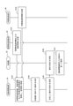
次に、図4および図5を参照して、本実施形態に係る湿度調整装置10を含むシステム1の動作について説明する。システム1の動作のうち、湿度調整装置10の動作は、本実施形態に係る湿度調整方法に相当する。図4は、システム1の動作の一例を示す。図5は、湿度調整装置10の制御部11の動作の一例を示すフローチャートである。本例においては、加湿器20が稼働中であるとする。
ステップS101において、空間部温湿度計30の制御部は、記憶部を参照し、空間部温度情報および湿度情報を、通信部を介して湿度調整装置10に送信する。
ステップS102において、内壁面温度計40の制御部は、記憶部を参照し、内壁面温度情報を、通信部を介して湿度調整装置10に送信する。
ステップS103において、湿度調整装置10の制御部11は、通信部13を介して、空間部温度情報、湿度情報、および内壁面温度情報を、空間部温湿度計30および内壁面温度計40から受信することで取得する。制御部11は、取得した空間部温度情報、湿度情報、および内壁面温度情報を記憶部12に格納する。
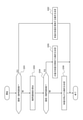
ステップS104において、制御部11は、加湿器20に指示する動作の決定を行う。図5は、ステップS104における動作の決定の具体的な処理フローを示す。
ステップS201において、動作決定部112は、記憶部12に格納された湿度情報と基準湿度値とを読み出す。動作決定部112は、湿度情報に含まれる湿度と基準湿度値とを比較し、湿度が基準湿度値未満であるかどうかを判断する。
湿度が基準湿度値未満である場合、動作決定部112は、ステップS202において、加湿器20が多量の加湿を実施するよう、加湿器20の動作を決定し、動作の決定の処理は終了する。湿度が基準湿度値以上である場合、動作の決定の処理はステップS203へと進む。本例において、湿度は95パーセントであり、基準湿度値は90パーセントである。湿度が基準湿度値以上であるため、動作の決定の処理はステップS203へと進む。
ステップS203において、臨界湿度値算出部111は、空間部温度情報、内壁面温度情報、および湿度情報を参照し、臨界湿度値の算出を行う。臨界湿度値算出部111は、算出した臨界湿度値を示す情報を動作決定部112に出力する。
次にステップS204において、動作決定部112は、湿度と臨界湿度値とを比較し、湿度が臨界湿度値未満であるかどうかを判断する。
湿度が臨界湿度値未満である場合、動作決定部112は、ステップS205において、加湿器20が少量の加湿を実施するよう、加湿器20の動作を決定し、動作の決定の処理は終了する。湿度が臨界湿度値以上である場合、動作決定部112は、ステップS206において、加湿器20が加湿を停止するよう、加湿器20の動作を決定する。本例において、湿度は95パーセントであり、臨界湿度値は94パーセントである。湿度が臨界湿度値以上であるため、動作決定部112は、ステップS206において、加湿を停止する動作を決定する。こうして加湿器20に指示する動作の決定の処理は終了する。
次に図4に戻ると、ステップS105において、動作決定部112は、通信部13を介して、決定した動作の処理を実施するよう動作の指示を加湿器20に送信する。このようにして、加湿器20が制御される。本例では、決定された動作は加湿を停止する動作であるため、制御部11は加湿器20に対し、通信部13を介して、加湿を停止する動作の指示を送信する。
ステップS106において、加湿器20の制御部は、通信部を介して、動作の指示を湿度調整装置10から受信する。本例では、加湿器20の制御部は、加湿を停止する動作の指示を受信する。
ステップS107において、加湿器20が湿度調整装置10からの指示に従って動作する。具体的には、加湿器20の制御部が、受信した指示に従って動作するよう加湿器20の各部を制御する。本例では、加湿を停止する動作を行うよう加湿器20のヒーター、ファン、および噴出口を制御する。
以上のステップS101~ステップS107によって、マンホールMの空間部Sの湿度が制御される。
上述のように、本実施形態にかかる湿度調整装置10は、マンホールMの空間部Sの湿度を示す湿度情報を取得し、該湿度情報に基づいて湿度を制御する制御部11を備える。
本実施形態によれば、鉄筋コンクリート製のマンホールM内の湿度を制御することができる。マンホールMの空間部Sの湿度が適切な値となるよう制御されることで、マンホールMを構成するコンクリートの中性化進行を防ぐことができる。
上述のように、本実施形態に係る湿度調整装置10において、制御部11は、マンホールMの空間部Sの温度を示す空間部温度情報と、マンホールMの内壁面Iの温度を示す内壁面温度情報とをさらに取得し、空間部温度情報と、内壁面温度情報と、湿度情報とに基づいてマンホールM内において結露が発生しない臨界湿度値を算出し、臨界湿度値と湿度とを比較した結果に基づいて湿度を制御する。
本実施形態によれば、マンホールMの空間部Sの温度および湿度と、内壁面Iに含まれる天井面Rの温度とに基づいて臨界湿度値が算出される。臨界湿度値と湿度とを比較して湿度を制御できるため、マンホールM内を加湿しすぎることにより結露が発生してしまうことを防ぐことができる。
上述のように、本実施形態にかかる湿度調整装置10は、マンホールM内を加湿する加湿器20と通信する通信部13をさらに備える。湿度調整装置10の制御部11は、湿度が基準湿度値以上且つ臨界湿度値未満の範囲で保たれるよう加湿器20の動作を決定し、決定した動作を通信部13を介して加湿器20に送信する。
本実施形態によれば、加湿器20の動作を制御することで、より精度よくマンホールM内の湿度を制御できる。加湿器20の動作により、マンホールM内の湿度を、コンクリートの中性化の進行が抑制され、且つ、結露が発生しない湿度に保つことができる。
(第2実施形態)
以下、第1実施形態と本実施形態との差異を説明する。
以下、第1実施形態と本実施形態との差異を説明する。
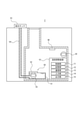
本実施形態に係るシステム2の概要を図6に示す。図6を参照すると、加湿器20の代わりに水供給装置50を備える点で第1実施形態と異なる。湿度調整装置10と、水供給装置50、空間部温湿度計30、および内壁面温度計40とは、有線または無線により通信可能に接続される。湿度調整装置10と、水供給装置50、空間部温湿度計30、および内壁面温度計40との間で情報を送受信するための通信方法は、特に限定されない。湿度調整装置10は、マンホールMの外に設置されてもよい。
水供給装置50は、マンホールMの空間部S内において水分が蒸発するよう水を液体の状態で保管する装置である。水供給装置50は、給水容器51、開閉可能な蓋52、給水タンク53、給水通路54、水位センサ55、給水ポンプ、モータ、制御部、記憶部および通信部を備える。水供給装置50の制御部は、蓋52、給水ポンプ、およびモータを制御する。本実施形態では、図6に示すように、給水タンク53は地上に設けられるが、マンホールM内に設けられてもよい。水供給装置50においては、水が給水ポンプによって給水タンク53から吸いあげられ、給水通路54へ送り込まれる。水は給水通路54の終端から給水容器51へと出る。給水容器51から水が蒸発することで、マンホールMが加湿される。給水ポンプはモータにより駆動され、モータは水供給装置50の制御部により制御される。水位センサ55は給水容器51内の水位を検出する。水供給装置50の制御部は水位センサ55が検出した水位を取得し、給水容器51内の水量を算出し、水量情報として記憶部に格納する。水量は、予め記憶部に格納された給水容器51の容積に基づいて算出することができる。水供給装置50の制御部は、水量情報を通信部を介して湿度調整装置10に送信する。水量情報の送信は常時行われてもよいし、湿度調整装置10からの指示に応じて行ってもよい。蓋52が開閉することで、水供給装置50からの水分の蒸発量が調整される。水供給装置50の制御部は、湿度調整装置10の制御部11から受信した指示に応じて水供給装置50全体の動作を制御する。
図7は本実施形態に係るシステム2の構成を示すブロック図である。図7に示す湿度調整装置10では、図3に示す第1実施形態の湿度調整装置10と比較して、湿度調整装置10が加湿器20の代わりに水供給装置50と通信する点、水供給装置50から湿度調整装置10に情報が送信される点、制御部11がさらに必要水量算出部113を備える点において、第1実施形態と異なる。
湿度調整装置10の制御部11は、第1実施形態と同様、湿度情報と、空間部温度情報と、内壁面温度情報とを取得する。制御部11はさらに、水供給装置50内の水量を示す水量情報を水供給装置50から取得する。制御部11は、取得した湿度情報、空間部温度情報、内壁面温度情報および水量情報を記憶部12に格納する。臨界湿度値算出部111は、第1実施形態と同様に臨界湿度値を算出する。必要水量算出部113は、空間部温度情報と、内壁面温度情報と、湿度情報と、臨界湿度値を示す情報とに基づいて、水供給装置50の必要水量を算出する。動作決定部112は、湿度が基準湿度値以上且つ臨界湿度値未満の範囲で保たれるよう水供給装置50の動作を決定する。具体的には、動作決定部112は、必要水量と水供給装置50内の水量とを比較した結果に基づいて水供給装置50の動作を決定する。制御部11は、決定された動作の指示を水供給装置50に送信する。水供給装置50は指示を受信し、指示に基づいて動作を行う。
「必要水量」は、マンホールMの空間部Sの湿度を臨界湿度値にするために不足している水量である。必要水量は、具体的には、以下に示すように水蒸気量として算出される。
制御部11は、以下に詳細に説明するように、マンホールMの空間部Sの湿度を制御する。制御は、動作決定部112が決定した動作の指示を、通信部13を介して水供給装置50に送信することで行われる。
まず、第1実施形態と同様、制御部11は、空間部温度情報、湿度情報、および内壁面温度情報を取得する。制御部11はさらに水供給装置50から、水量情報を、通信部13を介して受信することで取得する。制御部11は、定期的または非定期的に空間部温度情報、湿度情報、内壁面温度情報、および水量情報を取得してよい。
次に動作決定部112は、第1実施形態と同様、湿度情報に含まれる湿度と基準湿度値とを比較し、湿度が基準湿度値未満であるかどうかを判断する。
動作決定部112は、湿度が基準湿度値未満であると判断した場合、水供給装置50が水を取り込むよう、水供給装置50の動作を決定する。動作決定部112は、通信部13を介して、水供給装置50に動作の指示を送信する。「水を取り込む」とは、本実施形態では、水供給装置50の制御部がモータまたは蓋52を制御し、給水容器51内に水を足す、または蒸発を防ぐことをいうが、水供給装置50の機能によって自由に定められてよい。
臨界湿度値算出部111は、第1実施形態と同様の手法により臨界湿度値の算出を行う。臨界湿度値算出部111は算出した臨界湿度値を示す情報を必要水量算出部113に出力する。
必要水量算出部113は、湿度情報、空間部温度情報、内壁面温度情報、および臨界湿度値を示す情報を参照し、水供給装置50に供給する必要水量の算出を行う。必要水量算出部113はまず、以下の式(6)に基づいてAの値を算出する。

式(6)においてaはマンホールMの空間部Sの温度がTのときの飽和水蒸気量の値であり、算出方法については、第1実施形態に示す方法と同様であるため、説明を省略する。式(6)においてVはマンホール内空間体積であり、単位はm3である。RHは空間部Sの湿度であり、単位はパーセントである。算出されるAはマンホールMの空間部Sに存在する水蒸気量であり、単位はgである。
必要水量算出部113は次に、以下の式(7)に基づいて、Bの値を算出する。

式(7)において、a’×Vの項は、マンホールMの空間部Sの湿度が臨界湿度値であるときに空間部S内に存在する水蒸気量を示す。算出されるBは、マンホールMの空間部Sの湿度を臨界湿度値にするために不足している水蒸気量であり、単位はgである。
必要水量算出部113はこのようにして算出した水蒸気量を、必要水量として動作決定部112に出力する。当該必要水量の水が空間部S内に蒸発することで、空間部S内の湿度は臨界湿度値に近づく。このように、必要水量を算出して用いることで空間部Sの湿度が基準湿度値以上且つ臨界湿度値未満の範囲で保つことができる。
動作決定部112は、水量情報に含まれる水量が、当該必要水量以上であるかどうかを判断する。
動作決定部112は、湿度が基準湿度値以上であり、且つ水量が必要水量以上であると判断した場合、水供給装置50が給水容器51に水を取り込むことを停止するよう、水供給装置50の動作を決定する。動作決定部112は、通信部13を介して、水供給装置50に動作の指示を送信する。
動作決定部112は、湿度が基準湿度値以上であり、且つ水量が必要水量未満であると判断した場合、水供給装置50が給水容器51に水を取り込むよう、水供給装置50の動作を決定する。動作決定部112は、通信部13を介して、水供給装置50に動作の指示を送信する。
図8に、本実施形態に係る水供給装置50を用いてマンホールMの空間部Sの湿度を制御した結果を示す。図8はマンホールMの空間部Sの湿度の変化を示すグラフである。縦軸はマンホールMの空間部Sの湿度を、横軸は湿度を計測した日付である。2019年5月20日に、マンホールM内に設置された水供給装置50の給水容器51内の水を完全に取り除き、マンホールM内の空間部Sの湿度を外気と等しい湿度に設定した。その後、給水容器51内に水を供給し、マンホールMの鉄蓋230を閉じた。図8のグラフから、水供給装置50を配置した2019年5月20日から約10日間はマンホールM内の湿度の値が上下に変化していることがわかる。当該変化は、マンホールM内の温度の変化に伴い飽和水蒸気量が変化した結果、このような挙動が示されたと考えられる。一方、2019年5月20日から10日目の2019年5月30日以降については、マンホールMの空間部Sの湿度はほぼ100パーセントと高湿度で保たれているである。これは設置された水供給装置50からの水の蒸発作用によるものと考えられる。図8が示すように、水供給装置50を用いて、マンホールMの空間部Sの湿度の制御が有効に行えることがわかる。
次に、第1実施形態に係るシステム1の動作と本実施形態に係るシステム2の動作との差異を説明する。図9はシステム2の動作の一例を示す。図10は、本実施形態に係る湿度調整装置10の制御部11の動作の一例を示すフローチャートである。本例においては、水供給装置50に水が供給されているものとする。
図8のステップS301~ステップS302までは、第1実施形態の図4におけるステップS101~ステップS102と同様であるため説明を省略する。
ステップS303において、水供給装置50の制御部は、記憶部を参照し、水供給装置50内の水量を示す水量情報を、通信部を介して湿度調整装置10に送信する。
ステップS304において、湿度調整装置10の制御部11は、通信部13を介して、空間部温度情報、湿度情報、内壁面温度情報、および水量情報を、空間部温湿度計30、内壁面温度計40および水供給装置50から受信することで取得する。制御部11は、取得した空間部温度情報、湿度情報、内壁面温度情報、および水量情報を記憶部12に格納する。
ステップS305において、制御部11は、水供給装置50に指示する動作の決定を行う。図10は、ステップS305における動作の決定の具体的な処理フローを示す。
ステップS401において、動作決定部112は、記憶部12に格納された湿度情報と基準湿度値とを読み出す。動作決定部112は、湿度情報に含まれる湿度と基準湿度値とを比較し、湿度が基準湿度値未満であるかどうかを判断する。
湿度が基準湿度値未満である場合、動作決定部112は、ステップS402において水供給装置50が水を取り込むよう、水供給装置50の動作を決定し、動作の決定の処理は終了する。湿度が基準湿度値以上である場合、動作の決定の処理はステップS403へと進む。本例において、湿度は95パーセントであり、基準湿度値は90パーセントである。湿度が基準湿度値以上であるため、動作の決定の処理はステップS403へと進む。
ステップS403において、臨界湿度値算出部111は、空間部温度情報、内壁面温度情報、および湿度情報を参照し、臨界湿度値の算出を行う。臨界湿度値算出部111は、算出した臨界湿度値を示す情報を必要水量算出部113に出力する。
ステップS404において、必要水量算出部113は、湿度情報、空間部温度情報、内壁面温度情報、および臨界湿度値を示す情報を参照し、水供給装置50に供給する必要水量の算出を行う。必要水量算出部113は、算出した必要水量を示す情報を動作決定部112に出力する。
次にステップS405において、動作決定部112は、水量と必要水量とを比較し、水量が必要水量以上であるかどうかを判断する。
水量が必要水量以上である場合、動作決定部112は、ステップS406において水供給装置50が水を取り込むことを停止するよう、水供給装置50の動作を決定し、動作の決定の処理は終了する。水量が必要水量未満である場合、動作決定部112は、ステップS402において水供給装置50が水を取り込むよう、水供給装置50の動作を決定する。本例において、水量は必要水量未満である。よって、動作決定部112は、ステップS402において水供給装置50が水を取り込むよう、水供給装置50の動作を決定する。こうして水供給装置50に指示する動作の決定の処理は終了する。
次に図9に戻ると、ステップS306において、動作決定部112は、通信部13を介して、決定した動作の処理を実施するよう動作の指示を水供給装置50に送信する。このようにして、水供給装置50が制御される。本例では、決定された動作は水を取り込む動作であるため、制御部11は水供給装置50に対し、通信部13を介して、水を取り込む動作の指示を送信する。
ステップS307において、水供給装置50の制御部は、通信部を介して、動作の指示を湿度調整装置10から受信する。本例では、水供給装置50の制御部は、水を取り込む動作の指示を受信する。
ステップS308において、水供給装置50が湿度調整装置10からの指示に従って動作する。具体的には、水供給装置50の制御部が、受信した指示に従って動作するよう水供給装置50の各部を制御する。本例では、水を取り込む動作を行うよう水供給装置50のモータを制御する。
以上のステップS301~ステップS308によって、マンホールMの空間部Sの湿度が制御される。
上述のように、本実施形態にかかる湿度調整装置10は、マンホールM内に設置される水供給装置50と通信する通信部13をさらに備える。湿度調整装置10の制御部11は、湿度が基準湿度値以上且つ臨界湿度値未満の範囲で保たれるよう水供給装置50の動作を決定し、決定した動作を通信部13を介して水供給装置50に送信する。
本実施形態によれば、水供給装置50の動作を制御することで、より精度よくマンホールM内の湿度を制御できる。水供給装置50の動作により、マンホールM内の湿度を、コンクリートの中性化の進行が抑制され、且つ、結露が発生しない湿度に保つことができる。
上述のように、本実施形態にかかる湿度調整装置10において、制御部11は、水供給装置50内の水量を示す水量情報を取得し、空間部温度情報と、内壁面温度情報と、湿度情報と、臨界湿度値を示す情報とに基づいて、水供給装置50の必要水量を算出し、必要水量と水供給装置50内の水量とを比較した結果に基づいて水供給装置50の動作を決定し、決定した動作を通信部13を介して水供給装置50に送信する。
本実施形態によれば、マンホールMの空間部Sの温度および湿度と、内壁面Iに含まれる天井面Rの温度とに基づいて、水供給装置50の必要水量がより正確に算出される。算出した必要水量に基づいて水供給装置50が給水容器51に水を取り込む動作を制御できるため、マンホールM内を常に適切な湿度に保つことができる。
本開示を諸図面や実施形態に基づき説明してきたが、当業者であれば本開示に基づき種々の変形や修正を行うことが容易であることに注意されたい。従って、これらの変形や修正は本開示の範囲に含まれることに留意されたい。
(変形例1)
本開示の変形例として、湿度調整装置10の制御部11がさらに密閉性判断部114を備えてもよい。
本開示の変形例として、湿度調整装置10の制御部11がさらに密閉性判断部114を備えてもよい。
密閉性判断部114は、以下に詳細に説明するように、マンホールM内の密閉性があるかどうかについての判断を行う。
密閉性判断部114はまず、記憶部12に格納された湿度情報と、記憶部12に予め格納された、マンホールMを構成するコンクリートの吸湿性を示す吸湿性情報とを読み出す。「吸湿性情報」は、湿度低下量基準値、湿度変化基準傾向、および湿度低下の継続時間基準値を含む。ここで、当該吸湿性情報は、マンホールMを構成するコンクリートの調湿性に応じて設定される。コンクリートの調湿性とは、以下の文献5および文献6に開示されている通り、コンクリートが、周囲の環境と比較して乾燥している場合には吸湿を行い、湿っている場合には放湿を行う性能をいう。
文献5:田中宏行、外1名「骨材の違いによるセメント系固化物の空隙構造の違いと調湿性能」、平成24年度土木学会全国大会第67回年次学術講演会、V-448、2012年
文献6:呉藤勝彦、外1名「ゼオライト-セメント系硬化体の組織と調湿性」、Journal of the Ceramic Society of Japan、Vol.113、No.1、pp.736-742、2005年
文献5:田中宏行、外1名「骨材の違いによるセメント系固化物の空隙構造の違いと調湿性能」、平成24年度土木学会全国大会第67回年次学術講演会、V-448、2012年
文献6:呉藤勝彦、外1名「ゼオライト-セメント系硬化体の組織と調湿性」、Journal of the Ceramic Society of Japan、Vol.113、No.1、pp.736-742、2005年
「湿度低下量基準値」は、マンホールM内の湿度の低下量の基準を示す値である。密閉されたマンホールM内における、一定の時間における湿度の低下量を予め測定し、該低下量を湿度低下量基準値とする。コンクリートによる吸湿の速度は遅く、該コンクリートで構成されたマンホールM内の湿度低下量は比較的小さいことがわかっている。よって、密閉されたマンホールM内における湿度の低下量を予め測定しておき基準値とすることができる。
「湿度変化基準傾向」は、マンホールM内の湿度の経時的な変化の傾向を示す。密閉されたマンホールM内において、一定の時間における湿度の変化の傾向を予め測定し、該傾向を湿度変化基準傾向とする。マンホールは大きさ及び形状が規格によって定められており、同一の大きさ及び形状のマンホールにおいては、コンクリートの吸湿機能による湿度の変化の傾向も同様となる。よって同一の大きさ及び形状のマンホールにおける湿度の変化の傾向を予め把握しておき、これを他のマンホールについて判断するための基準とすることができる。
「継続時間基準値」は、マンホールM内の湿度の低下の継続時間を示す値である。密閉されたマンホールM内において、湿度の低下が継続する時間を予め測定し、該時間を継続時間基準値とする。コンクリートの吸湿による湿度の低下は、マンホール内が高湿度環境に保たれている限り一定の時間の経過後に停止するが、密閉性が低いマンホールでは、湿度の低下が停止しないか、一旦停止しても再開する。よって湿度の低下の継続時間を予め測定しておき、基準値とすることができる。
密閉性判断部114は、湿度情報に含まれる湿度と、湿度変化基準傾向、湿度低下量基準値、または継続時間基準値とを比較することでマンホールMの密閉性があるかどうかについての判断を行う。例えば、密閉性判断部114は、湿度の変化の傾向が湿度変化基準傾向と一致しているとき、マンホールMの密閉性があると判断する。例えば、密閉性判断部114は、湿度の低下量が当該湿度低下量基準値未満であるとき、マンホールMの密閉性があると判断する。例えば、密閉性判断部114は、湿度の低下の継続時間が継続時間基準値未満であるとき、マンホールMの密閉性があると判断する。密閉性判断部114は、湿度変化基準傾向、湿度低下量基準値、または継続時間基準値のいずれか1つのみを用いて密閉性についての判断を行ってもよいし、複数を用いて判断を行ってもよい。
制御部11は、密閉性判断部114が判断した結果を、出力部15を介してユーザに対し通知する。このようにして、ユーザはマンホールMの密閉性が把握することができる。制御部11は判断した結果を、通信部13を介して、マンホールMの点検を行うユーザの端末装置に送信してもよい。
本変形例において、動作決定部112は、密閉性判断部114が判断した結果に応じて、加湿器20または水供給装置50が行う動作を決定してもよい。例えば、密閉性判断部114がマンホールMの密閉性がないと判断した場合、動作決定部112は加湿器20が多量の加湿を実施するよう、加湿器20の動作を決定してもよい。例えば、密閉性判断部114がマンホールMの密閉性がないと判断した場合、動作決定部112は水供給装置50が水を取り込むよう、水供給装置50の動作を決定してもよい。動作決定部112が決定した動作の指示を、通信部13を介して、加湿器20または水供給装置50に送信し、加湿器20または水供給装置50が当該指示に従って動作してもよい。
上述のように、本変形例に係る湿度調整装置10において、制御部11は、湿度情報に基づいてマンホールM内の密閉性があるかどうかについての判断を行う。
本変形例によれば、マンホールMの密閉性の有無を容易に把握することができる。密閉性を把握することで、マンホールM内の湿度を適当に保つことができる他、マンホールMの鉄蓋230が外れていること、またはマンホールM内に破損個所が存在していること等を早期に発見できる。よって、マンホールMにおいて事故が発生することを防ぐことができる。
上述のように、本変形例に係る湿度調整装置10の制御部11は、マンホールMを構成するコンクリートの調湿性に基づいて密閉性を判断する。
本変形例によれば、マンホールM内の湿度が低下している場合に、当該低下がマンホールMを構成するコンクリートの吸湿によるものなのか、または密閉性が無いことによるものなのかについての判断が容易となる。よって、マンホールM内の密閉性の有無をより精度よく把握することができる。
(変形例2)
本開示の変形例として、湿度調整装置10がさらに除湿装置を備えてもよい。本変形例では、湿度調整装置10が加湿器20または水供給装置50の動作を制御することに加えて、除湿装置を制御する。
本開示の変形例として、湿度調整装置10がさらに除湿装置を備えてもよい。本変形例では、湿度調整装置10が加湿器20または水供給装置50の動作を制御することに加えて、除湿装置を制御する。
本変形例によれば、除湿装置の除湿機能を用いることで、マンホールM内の湿度の調整をより素早く正確に行うことができる。例えば、マンホールMの外の湿度が高い場合、または雨水がマンホールM内に侵入した場合等に、除湿装置により、素早く空間部Sの湿度を減じ、湿度が臨界湿度値に達してしまうことを防ぐことができる。
(変形例3)
本開示の変形例として、湿度調整装置10の制御部11は、マンホールMの天井面Rの温度を、内壁面温度計40から取得する代わりに、空間部温度情報に含まれる温度から推定してもよい。例えば、制御部11は、空間部温度情報に含まれる温度と、予め記憶部12に格納していたマンホールMの深さとをパラメータとして解析して、天井面Rの温度を推定してよい。マンホールMの空間部Sの温度と、マンホールMの深さとをパラメータとして解析して天井面Rの温度を測定する方法の詳細については、例えば以下の文献7に開示されているため、説明は省略する。
文献7:渡邉一旭、外4名、「地盤と構造物の統合熱伝導解析による土中コンクリートマンホール内の温湿度環境の推定」、土木学会論文E2(材料・コンクリート構造)、Vol.76、No.2、pp.65-77、2020年
本開示の変形例として、湿度調整装置10の制御部11は、マンホールMの天井面Rの温度を、内壁面温度計40から取得する代わりに、空間部温度情報に含まれる温度から推定してもよい。例えば、制御部11は、空間部温度情報に含まれる温度と、予め記憶部12に格納していたマンホールMの深さとをパラメータとして解析して、天井面Rの温度を推定してよい。マンホールMの空間部Sの温度と、マンホールMの深さとをパラメータとして解析して天井面Rの温度を測定する方法の詳細については、例えば以下の文献7に開示されているため、説明は省略する。
文献7:渡邉一旭、外4名、「地盤と構造物の統合熱伝導解析による土中コンクリートマンホール内の温湿度環境の推定」、土木学会論文E2(材料・コンクリート構造)、Vol.76、No.2、pp.65-77、2020年
本変形例によれば、マンホールM内に内壁面温度計40を設置しなくとも制御部11が天井面Rの温度を取得できるため、より簡易な構成でマンホールM内の湿度を制御できる。
(変形例4)
本開示の変形例として、湿度調整装置10の制御部11は、マンホールMの空間部Sの温度を、空間部温湿度計30から取得する代わりに、センシング技術を用いて光ファイバーから取得してもよい。光ファイバーは、マンホールM内に設置されている通信用ケーブルに含まれる。光ファイバーのセンシング技術の詳細については、例えば以下の文献8に開示されているため、説明は省略する。
文献8:山口徳郎、外1名「分布光ファイバー温度センシング」、OKIテクニカルレビュー、第203号、Vol.84、No.2、2017年
本開示の変形例として、湿度調整装置10の制御部11は、マンホールMの空間部Sの温度を、空間部温湿度計30から取得する代わりに、センシング技術を用いて光ファイバーから取得してもよい。光ファイバーは、マンホールM内に設置されている通信用ケーブルに含まれる。光ファイバーのセンシング技術の詳細については、例えば以下の文献8に開示されているため、説明は省略する。
文献8:山口徳郎、外1名「分布光ファイバー温度センシング」、OKIテクニカルレビュー、第203号、Vol.84、No.2、2017年
本変形例によれば、マンホールM内の空間部温湿度計30を利用しなくとも、制御部11が空間部Sの温度を取得できるため、より簡易な構成でマンホールM内の湿度を制御できる。
(変形例5)
本開示の変形例として、湿度調整装置10は、加湿器20および水供給装置50の代わりに、または加湿器20および水供給装置50に加えて、吸放湿性を持つ吸放湿性材料(調湿材)を備えても良い。吸放湿性材料は例えば、マンホールMの内壁面I全体に沿って設置されてもよい。
本開示の変形例として、湿度調整装置10は、加湿器20および水供給装置50の代わりに、または加湿器20および水供給装置50に加えて、吸放湿性を持つ吸放湿性材料(調湿材)を備えても良い。吸放湿性材料は例えば、マンホールMの内壁面I全体に沿って設置されてもよい。
本変形例によれば、より簡易な構成によりマンホールM内の湿度を制御できる。
1,2 システム
10 湿度調整装置
11 制御部
12 記憶部
13 通信部
14 入力部
15 出力部
111 臨界湿度値算出部
112 動作決定部
113 必要水量算出部
114 密閉性判断部
20 加湿器
30 空間部温湿度計
40 内壁面温度計
50 水供給装置
51 給水容器
52 蓋
53 給水タンク
54 給水通路
55 水位センサ
210 首部
220 躯体部
230 鉄蓋
221 天井部
222 床部
223 側壁部
10 湿度調整装置
11 制御部
12 記憶部
13 通信部
14 入力部
15 出力部
111 臨界湿度値算出部
112 動作決定部
113 必要水量算出部
114 密閉性判断部
20 加湿器
30 空間部温湿度計
40 内壁面温度計
50 水供給装置
51 給水容器
52 蓋
53 給水タンク
54 給水通路
55 水位センサ
210 首部
220 躯体部
230 鉄蓋
221 天井部
222 床部
223 側壁部
Claims (8)
- マンホールの空間部の湿度を示す湿度情報を取得し、該湿度情報に基づいて前記湿度を制御する制御部を備える、湿度調整装置。
- 前記制御部は、マンホールの空間部の温度を示す空間部温度情報と、マンホールの内壁面の温度を示す内壁面温度情報とをさらに取得し、
該空間部温度情報と、該内壁面温度情報と、前記湿度情報とに基づいて前記マンホール内において結露が発生しない臨界湿度値を算出し、
該臨界湿度値と前記湿度とを比較した結果に基づいて前記湿度を制御する、請求項1に記載の湿度調整装置。 - 前記マンホール内を加湿する加湿器と通信する通信部をさらに備え、
前記制御部は、前記湿度が基準湿度値以上且つ前記臨界湿度値未満の範囲で保たれるよう前記加湿器の動作を決定し、決定した動作を前記通信部を介して前記加湿器に送信する、請求項2に記載の湿度調整装置。 - 前記マンホール内に設置される水供給装置と通信する通信部をさらに備え、
前記制御部は、前記湿度が基準湿度値以上且つ前記臨界湿度値未満の範囲で保たれるよう前記水供給装置の動作を決定し、決定した動作を前記通信部を介して前記水供給装置に送信する、請求項2に記載の湿度調整装置。 - 前記制御部は、
前記水供給装置内の水量を示す水量情報を取得し、
前記空間部温度情報と、前記内壁面温度情報と、前記湿度情報と、前記臨界湿度値を示す情報とに基づいて、前記水供給装置の必要水量を算出し、
前記必要水量と前記水供給装置内の水量とを比較した結果に基づいて前記水供給装置の動作を決定し、決定した動作を前記通信部を介して前記水供給装置に送信する、請求項4に記載の湿度調整装置。 - 前記制御部は、前記湿度情報に基づいて前記マンホール内の密閉性があるかどうかについての判断を行う、請求項1から5のいずれか一項に記載の湿度調整装置。
- 前記制御部は、前記マンホールを構成するコンクリートの調湿性に基づいて前記密閉性を判断する、請求項6に記載の湿度調整装置。
- マンホールの空間部の湿度を示す湿度情報を取得するステップと、
該湿度情報に基づいて前記湿度を制御するステップと、
を含む湿度調整方法。
Priority Applications (3)
| Application Number | Priority Date | Filing Date | Title |
|---|---|---|---|
| JP2022545262A JP7364968B2 (ja) | 2020-08-31 | 2020-08-31 | 湿度調整装置及び湿度調整方法 |
| PCT/JP2020/032905 WO2022044331A1 (ja) | 2020-08-31 | 2020-08-31 | 湿度調整装置及び湿度調整方法 |
| US18/022,953 US20230314018A1 (en) | 2020-08-31 | 2020-08-31 | Humidity adjusting device and humidity adjusting method |
Applications Claiming Priority (1)
| Application Number | Priority Date | Filing Date | Title |
|---|---|---|---|
| PCT/JP2020/032905 WO2022044331A1 (ja) | 2020-08-31 | 2020-08-31 | 湿度調整装置及び湿度調整方法 |
Publications (1)
| Publication Number | Publication Date |
|---|---|
| WO2022044331A1 true WO2022044331A1 (ja) | 2022-03-03 |
Family
ID=80354931
Family Applications (1)
| Application Number | Title | Priority Date | Filing Date |
|---|---|---|---|
| PCT/JP2020/032905 Ceased WO2022044331A1 (ja) | 2020-08-31 | 2020-08-31 | 湿度調整装置及び湿度調整方法 |
Country Status (3)
| Country | Link |
|---|---|
| US (1) | US20230314018A1 (ja) |
| JP (1) | JP7364968B2 (ja) |
| WO (1) | WO2022044331A1 (ja) |
Cited By (1)
| Publication number | Priority date | Publication date | Assignee | Title |
|---|---|---|---|---|
| CN115182604A (zh) * | 2022-07-29 | 2022-10-14 | 中建西部建设北方有限公司 | 一种大体积混凝土养护方法、装置及介质 |
Citations (6)
| Publication number | Priority date | Publication date | Assignee | Title |
|---|---|---|---|---|
| US4567939A (en) * | 1984-02-02 | 1986-02-04 | Dumbeck Robert F | Computer controlled air conditioning systems |
| JPH0643051U (ja) * | 1992-11-10 | 1994-06-07 | 株式会社クボタ | マンホール蓋およびピット構造 |
| JP2005350907A (ja) * | 2004-06-09 | 2005-12-22 | Jfe Engineering Kk | 半密閉構造を有する鋼構造物内部の防食方法及び防食設備 |
| JP2009063251A (ja) * | 2007-09-07 | 2009-03-26 | Panasonic Corp | 換気システム |
| JP2017036475A (ja) * | 2015-08-10 | 2017-02-16 | 富士通株式会社 | マンホール蓋防食システム |
| KR102045298B1 (ko) * | 2019-06-12 | 2019-11-18 | 주성이엔지(주) | 맨홀의 결로방지를 위한 환기 제어 장치 |
Family Cites Families (9)
| Publication number | Priority date | Publication date | Assignee | Title |
|---|---|---|---|---|
| US3326464A (en) * | 1965-06-01 | 1967-06-20 | Jr Asie C Rose | Method and apparatus for controlling the humidity within an enclosure |
| US3547348A (en) * | 1969-02-20 | 1970-12-15 | Westinghouse Electric Corp | Humidity control system |
| JPS55121145A (en) * | 1979-03-12 | 1980-09-18 | Matsushita Electric Ind Co Ltd | Humidity control circuit |
| KR930003925B1 (ko) * | 1991-02-25 | 1993-05-15 | 삼성전자 주식회사 | 분리형 에어 컨디셔너의 자동제어방법 |
| US9845961B2 (en) * | 2012-09-20 | 2017-12-19 | Mitsubishi Electric Corporation | Humidifier and method of hydrophilization processing for humidifying material |
| US11060754B2 (en) * | 2015-06-05 | 2021-07-13 | Novinium, Inc. | Ventilation system for manhole vault |
| US10962253B2 (en) * | 2015-06-05 | 2021-03-30 | Novinium, Inc. | Systems for circulating air inside a manhole vault |
| WO2017173402A2 (en) * | 2016-03-31 | 2017-10-05 | Novinium, Inc. | Smart system for manhole event suppression system |
| JP6889679B2 (ja) * | 2018-03-26 | 2021-06-18 | エスペック株式会社 | 温湿度調整装置、制御装置、制御方法及び制御プログラム |
-
2020
- 2020-08-31 WO PCT/JP2020/032905 patent/WO2022044331A1/ja not_active Ceased
- 2020-08-31 US US18/022,953 patent/US20230314018A1/en active Pending
- 2020-08-31 JP JP2022545262A patent/JP7364968B2/ja active Active
Patent Citations (6)
| Publication number | Priority date | Publication date | Assignee | Title |
|---|---|---|---|---|
| US4567939A (en) * | 1984-02-02 | 1986-02-04 | Dumbeck Robert F | Computer controlled air conditioning systems |
| JPH0643051U (ja) * | 1992-11-10 | 1994-06-07 | 株式会社クボタ | マンホール蓋およびピット構造 |
| JP2005350907A (ja) * | 2004-06-09 | 2005-12-22 | Jfe Engineering Kk | 半密閉構造を有する鋼構造物内部の防食方法及び防食設備 |
| JP2009063251A (ja) * | 2007-09-07 | 2009-03-26 | Panasonic Corp | 換気システム |
| JP2017036475A (ja) * | 2015-08-10 | 2017-02-16 | 富士通株式会社 | マンホール蓋防食システム |
| KR102045298B1 (ko) * | 2019-06-12 | 2019-11-18 | 주성이엔지(주) | 맨홀의 결로방지를 위한 환기 제어 장치 |
Cited By (2)
| Publication number | Priority date | Publication date | Assignee | Title |
|---|---|---|---|---|
| CN115182604A (zh) * | 2022-07-29 | 2022-10-14 | 中建西部建设北方有限公司 | 一种大体积混凝土养护方法、装置及介质 |
| CN115182604B (zh) * | 2022-07-29 | 2023-08-22 | 中建西部建设北方有限公司 | 一种大体积混凝土养护方法、装置及介质 |
Also Published As
| Publication number | Publication date |
|---|---|
| JP7364968B2 (ja) | 2023-10-19 |
| JPWO2022044331A1 (ja) | 2022-03-03 |
| US20230314018A1 (en) | 2023-10-05 |
Similar Documents
| Publication | Publication Date | Title |
|---|---|---|
| Zhou et al. | Influence of envelope properties on interior insulation solutions for masonry walls | |
| Soulios et al. | Hygrothermal performance of hydrophobized and internally insulated masonry walls-simulating the impact of hydrophobization based on experimental results | |
| JP2003252691A (ja) | コンクリートの養生方法及びその養生装置 | |
| JP7364968B2 (ja) | 湿度調整装置及び湿度調整方法 | |
| Niubó et al. | Magnesium phosphate cement formulated with low grade magnesium oxide with controlled porosity and low thermal conductivity as a function of admixture | |
| Hoła | Methodology for the in situ testing of the moisture content of brick walls: an example of application | |
| Zhan et al. | Assessing the hygrothermal performance of typical lightweight steel-framed wall assemblies in hot-humid climate regions by monitoring and numerical analysis | |
| Martel et al. | The monitoring of wall moisture in a property retrofitted with Internal Wall Insulation | |
| Engel et al. | Adapting hydrophobizing impregnation agents to the object | |
| Cambray et al. | Hydrophobic treatments and their application with internal wall insulation | |
| CN121168155A (zh) | 一种考虑温-湿耦合的大坝混凝土浇筑过程多场耦合的模拟方法及系统 | |
| Hansen et al. | Moisture transport properties of brick–comparison of exposed, impregnated and rendered brick | |
| Åhs | Redistribution of moisture and ions in cement based materials | |
| Hens | Heat, air and moisture transfer in highly insulated building envelopes (Hamtie) | |
| Salonvaara¹ et al. | Waterproof Coating on the Hygrothermal Performance of a Brick Fa | |
| Barysheva et al. | Thermophysical Properties of Aerated Concrete Enclosing Structures | |
| Leiten et al. | Hygrothermal Assessment of Natural Insulation Materials Employed for Internal Use in Historic Masonry | |
| Cambray et al. | An overview of hydrophobic treatments and their application with Internal Wall Insulation | |
| Zhu | Moisture and Brick Cavity Masonry: Performance and Properties of Surface Treated Waterproofing Products | |
| Kurnitski | Humidity control in outdoor-air-ventilated crawl spaces in cold climate by means of ventilation, gorund covers and dehumidification | |
| CN114398793B (zh) | 乏燃料水池通风系统室内空气参数的设计方法及装置 | |
| Nilsson et al. | Durability of reinforced concrete structures and penetrability | |
| Філоненко et al. | Investigation of the thermal and moisture regime of cold attics using an instrumental method= Дослідження тепловологісного режиму холодних горищ інструментальним методом | |
| Hu et al. | Chloride transmission in silane composite emulsion-protected concrete under the coupling effect of flexural loading and wetting–drying cycles | |
| Cambray et al. | The Influence of Application Rate of Hydrophobic Treatments on the Drying Behaviour of Brick |
Legal Events
| Date | Code | Title | Description |
|---|---|---|---|
| 121 | Ep: the epo has been informed by wipo that ep was designated in this application |
Ref document number: 20951580 Country of ref document: EP Kind code of ref document: A1 |
|
| ENP | Entry into the national phase |
Ref document number: 2022545262 Country of ref document: JP Kind code of ref document: A |
|
| NENP | Non-entry into the national phase |
Ref country code: DE |
|
| 122 | Ep: pct application non-entry in european phase |
Ref document number: 20951580 Country of ref document: EP Kind code of ref document: A1 |