WO2022044191A1 - 調整システム、調整方法および調整プログラム - Google Patents
調整システム、調整方法および調整プログラム Download PDFInfo
- Publication number
- WO2022044191A1 WO2022044191A1 PCT/JP2020/032340 JP2020032340W WO2022044191A1 WO 2022044191 A1 WO2022044191 A1 WO 2022044191A1 JP 2020032340 W JP2020032340 W JP 2020032340W WO 2022044191 A1 WO2022044191 A1 WO 2022044191A1
- Authority
- WO
- WIPO (PCT)
- Prior art keywords
- cost function
- change
- actual data
- error
- adjustment
- Prior art date
- Legal status (The legal status is an assumption and is not a legal conclusion. Google has not performed a legal analysis and makes no representation as to the accuracy of the status listed.)
- Ceased
Links
Images


Classifications
-
- G—PHYSICS
- G05—CONTROLLING; REGULATING
- G05B—CONTROL OR REGULATING SYSTEMS IN GENERAL; FUNCTIONAL ELEMENTS OF SUCH SYSTEMS; MONITORING OR TESTING ARRANGEMENTS FOR SUCH SYSTEMS OR ELEMENTS
- G05B13/00—Adaptive control systems, i.e. systems automatically adjusting themselves to have a performance which is optimum according to some preassigned criterion
- G05B13/02—Adaptive control systems, i.e. systems automatically adjusting themselves to have a performance which is optimum according to some preassigned criterion electric
- G05B13/0265—Adaptive control systems, i.e. systems automatically adjusting themselves to have a performance which is optimum according to some preassigned criterion electric the criterion being a learning criterion
-
- B—PERFORMING OPERATIONS; TRANSPORTING
- B25—HAND TOOLS; PORTABLE POWER-DRIVEN TOOLS; MANIPULATORS
- B25J—MANIPULATORS; CHAMBERS PROVIDED WITH MANIPULATION DEVICES
- B25J13/00—Controls for manipulators
-
- B—PERFORMING OPERATIONS; TRANSPORTING
- B25—HAND TOOLS; PORTABLE POWER-DRIVEN TOOLS; MANIPULATORS
- B25J—MANIPULATORS; CHAMBERS PROVIDED WITH MANIPULATION DEVICES
- B25J9/00—Program-controlled manipulators
- B25J9/16—Program controls
- B25J9/1628—Program controls characterised by the control loop
- B25J9/163—Program controls characterised by the control loop learning, adaptive, model based, rule based expert control
-
- G—PHYSICS
- G06—COMPUTING OR CALCULATING; COUNTING
- G06N—COMPUTING ARRANGEMENTS BASED ON SPECIFIC COMPUTATIONAL MODELS
- G06N20/00—Machine learning
Definitions
- the present invention relates to an adjustment system, an adjustment method, and an adjustment program for adjusting the control contents of a system including a device to be controlled.
- Patent Document 1 describes a method of constructing a learning model for improving the selection accuracy of an object extraction position.
- teacher data in which an evaluation value is given to matching point cloud information in which an object extraction position taught by a user with respect to a distance image and image data in the vicinity thereof are associated with each other is used.
- a learning model is constructed by using supervised machine learning.
- a machine coordinate system for controlling a robot and an object extraction position (camera coordinate system) are associated with each other by calibration performed in advance by an image processing device or a robot control device. It is assumed that you are there. Therefore, if the learning environment and the control environment are different, such as when the position of the camera is changed or the camera is changed to a new camera, it may not be possible to properly control the device.
- an object of the present invention is to provide an adjustment system, an adjustment method, and an adjustment program capable of efficiently adjusting parameters according to changes in circumstances.
- the adjustment system has an input unit that accepts input of unchanged actual data acquired by the device before change and changed actual data acquired by the changed device under the control using the first cost function. , It is equipped with an update unit that generates a second cost function that updates the first cost function so as to reduce the difference between the actual data before change and the actual data after change. It is characterized in that an error occurring in the output value of the device included in the first cost function is estimated to generate a second cost function in which the first cost function is updated.
- the adjustment method accepts the input of the unchanged actual data acquired by the device before the change and the changed actual data acquired by the changed device under the control using the first cost function, and before the change.
- a second cost function is generated by updating the first cost function so as to reduce the difference between the actual data and the changed actual data. It is characterized in that an error occurring in the output value of the device included in the cost function of is estimated and a second cost function is generated by updating the first cost function.
- the adjustment program accepts the input of the unchanged actual data acquired by the device before the change and the changed actual data acquired by the changed device to the computer under the control using the first cost function.
- the input process and the update process to generate the second cost function that updated the first cost function are executed so as to reduce the difference between the actual data before the change and the actual data after the change. It is characterized in that an error occurring in the output value of the device included in the first cost function is estimated before and after the change of, and a second cost function is generated by updating the first cost function.
- the devices to be mounted for example, sensors, actuators, etc.
- a system that requires adjustment of these devices and adjustment of a cost function (reward function) used for controlling the devices is provided.
- the change here includes, for example, changing the model of the sensor, changing the mounting position, the angle, and the like.
- a system to be adjusted such a system will be referred to as a system to be adjusted.
- An example of a system to be adjusted is a robot arm.
- the robot arm is equipped with, for example, a camera for measuring the distance to an object, a pressure sensor used when grasping an object, an actuator for driving the arm, and the like, and a cost function is used to control these. ..
- a camera for measuring the distance to an object
- a pressure sensor used when grasping an object
- an actuator for driving the arm
- a cost function is used to control these. ..
- a cost function is used to control these. ..
- a method of adjusting the cost function in consideration of the entire system to be adjusted will be described.
- the adjustment target system of this embodiment is not limited to the robot arm.
- systems in various fields such as a device that automatically determines a person and a vehicle that automatically drives can be the target of the adjustment system of the present embodiment.
- FIG. 1 is a block diagram showing a configuration example of an embodiment of the adjustment system according to the present invention.
- the adjustment system 100 of the present embodiment is connected to the adjustment target system 200 and notifies information of various values necessary for adjustment. Further, the adjustment system 100 acquires the actual data measured by the adjustment target system 200.
- the first phase is a phase in which actual data is measured in a state where the performance of various sensors included in the adjustment target system 200 is known.
- the actual data measured in the first phase is referred to as the actual data before change.
- the second phase is a phase in which actual data is measured in a state where various sensors included in the adjustment target system 200 are changed.
- the actual data measured in the second phase is referred to as the changed actual data.
- the actual data is a set of actual values acquired in the environment before or after the change of the sensor or the like, and can be said to be locus data indicating the operation of the adjustment target system 200. Further, in the present embodiment, it is assumed that the measured actual data is the locus data including the observed state and the action performed by an expert or the like for the state. That is, this actual value can be said to be the series data of the state and the behavior in the reverse reinforcement learning.
- the information indicating the state includes a camera image, coordinates and axis angles of each arm joint, speed (rotational speed), and the like.
- actions include the angle of each joint in the actuator and the distance between the arm and the object in the camera.
- the actual data before the change is the locus data of the ideal state in which the known sensor or the like is operating without any problem, and the actual data after the change is after the sensor or the like is changed (for example, unknown). It is assumed that the locus data does not show the ideal movement by the sensor etc.).
- the goal is to update the cost function so that the actual data after the change is closer to the actual data before the change.
- the adjustment target system 200 includes a control unit 210, a sensor 211, and an actuator 212.
- the sensor 211 and the actuator 212 included in the adjustment target system 200 illustrated in FIG. 1 are examples of the sensor and the like to be changed, and the change target is not limited to the sensor and the actuator.
- the control unit 210 controls various actuators (actuator 212 in the example shown in FIG. 1) of the system to be adjusted 200 by using the cost function for control (more specifically, by optimizing the cost function). do. Further, the control unit 210 may control various actuators based on a predetermined control logic. The control unit 210 receives the adjustment value adapted to the changed environment obtained by the processing of the adjustment system 100 described later, and uses the cost function changed based on the received adjustment value to adjust the adjustment target system 200. Controls various actuators.
- control unit 210 acquires the actual data from each device by the control using the cost function and outputs it to the adjustment system 100. Specifically, the control unit 210 generates pre-change actual data in the first phase and outputs it to the adjustment system 100, and generates post-change actual data in the second phase and outputs it to the adjustment system 100. The control unit 210 may store the actual data in an external storage (not shown) separate from the adjustment system 100.
- the control unit 210 is realized by, for example, various control units.
- the control unit 210 may be realized by, for example, a processor of various general-purpose computers (for example, a CPU (Central Processing Unit) or a GPU (Graphics Processing Unit)), and may be realized by a dedicated control unit (for example, an ECU in the case of an automobile). It may be realized by (Engine Control Unit, etc.).
- a processor of various general-purpose computers for example, a CPU (Central Processing Unit) or a GPU (Graphics Processing Unit)
- a dedicated control unit for example, an ECU in the case of an automobile. It may be realized by (Engine Control Unit, etc.).
- the adjustment system 100 includes a locus data acquisition device 10 and a learning device 20.
- the locus data acquisition device 10 includes a performance data input unit 11, a data processing processing unit 12, and a performance data storage unit 13.
- the actual data input unit 11 accepts the input of the actual data generated by the adjustment target system 200.
- the actual data input unit 11 may accept input of actual data directly from the adjustment target system 200, or may acquire and input actual data from the above-mentioned external storage (not shown).
- the data processing unit 12 processes the actual data to generate data (learning data) in a format that can be used when the learning device 20 described later performs learning.
- the data processing unit 12 can use any method for processing the learning data. Examples of the training data processing method include standardization of data formats, data cleansing, and feature quantity generation.
- the feature amount (explanatory variable) used for the learning data may be designed in advance, and the data processing unit 12 may generate the designed feature amount based on the input actual data.
- the actual data storage unit 13 stores the actual data 13b before the change and the actual data 13a after the change.
- the actual data storage unit 13 may store the learning data obtained by processing the unchanged actual data 13b and the learning data obtained by processing the changed actual data 13a.
- the actual data storage unit 13 is realized by, for example, a magnetic disk or the like.
- the learning device 20 includes a learning data input unit 21, a parameter estimation processing unit 22, an output unit 23, and a parameter storage unit 24.
- the learning data input unit 21 receives input of learning data from the locus data acquisition device 10.
- the learning data input unit 21 may directly accept the input of the learning data generated by the data processing unit 12, or may acquire the learning data from the actual data storage unit 13 and input the learning data.
- the learning data input unit 21 may perform the data processing processing performed by the data processing processing unit 12. In this case, the learning data input unit 21 may accept the input of the pre-change actual data and the post-change actual data from the locus data acquisition device 10.
- the parameter estimation processing unit 22 estimates the parameters of the cost function using the input learning data. Hereinafter, the operation of the parameter estimation processing unit 22 will be described separately for the first phase and the second phase.
- the parameter estimation processing unit 22 estimates the parameters of the cost function by learning the cost function using the learning data created based on the actual data before the change.
- the cost function learned based on the actual data before change may be referred to as the cost function before change or the first cost function.
- the parameter estimation processing unit 22 estimates the weight of the feature amount as a parameter of the cost function using the learning data created based on the actual data before the change.
- the parameter estimation processing unit 22 may generate, for example, a cost function as shown in Equation 1 illustrated below by machine learning.
- the cost function exemplified by Equation 1 is a measured sensor output (or a feature amount calculated based on the sensor output) st and each sensor output (or the above-mentioned feature amount) that can affect the control logic.
- Target value s ⁇ (superficial bar of s) This is a cost function expressed by the sum of the differences from t .
- ⁇ s is a parameter estimated by learning in the first phase, and is a weight of each feature amount.
- the cost function exemplified in Equation 1 may be, for example, a cost function used for controlling the actuator 212.
- the method by which the parameter estimation processing unit 22 estimates the parameters of the cost function is not particularly limited.
- the parameter estimation processing unit 22 estimates the parameters of the cost function by inverse reinforcement learning. You may.
- the parameter estimation processing unit 22 learns the unchanged cost function in the first phase.
- the pre-change cost function may be generated in advance by another means other than the parameter estimation processing unit 22 of the present embodiment and stored in the parameter storage unit 24 described later. In this case, the parameter estimation processing unit 22 does not have to generate the cost function in the first phase.
- the parameter estimation processing unit 22 sets the pre-change cost function so as to bring the post-change actual data closer to the pre-change actual data (in other words, to reduce the difference between the pre-change actual data and the post-change actual data).
- Update the cost function updated in this way will be referred to as a changed cost function or a second cost function.
- the parameter estimation processing unit 22 does not change the already estimated parameters (specifically, the weight of the feature amount), and the output value (feature amount) of the device included in the pre-change cost function before and after the change of the device. ) Is estimated and the modified cost function is generated.
- the parameter estimation processing unit 22 first sets a variable indicating an error in the sensor output (output value or feature amount calculated based on the sensor output) of the device caused by the change in the pre-change cost function.
- a function (changed cost function) may be generated.
- the parameter estimation processing unit 22 may generate a cost function after the change by updating the variable so as to reduce the difference between the actual data before the change and the actual data after the change and estimating the error.
- the parameter estimation processing unit 22 may generate the changed cost function exemplified in the following equation 2 in which the bias ⁇ s of the feature amount generated by the change of the sensor is set in the pre-change cost function.
- the parameter estimation processing unit 22 estimates the bias ⁇ s while updating the cost function after the change so as to reduce the difference between the actual data before the change and the actual data after the change while keeping ⁇ s fixed.
- the method by which the parameter estimation processing unit 22 estimates the error is not particularly limited. Even if the parameter estimation processing unit 22 estimates the error by generating an updated cost function after the change in the framework of inverse reinforcement learning using the actual data before the change and the actual data after the change, for example. good. In this case, the parameter estimation processing unit 22 updates the cost function (specifically, an error such as a bias) so as to reduce the difference between the actual data before the change and the actual data after the change, and the updated cost.
- the error may be estimated by repeating the process of updating the cost function so as to reduce the difference between the decision data obtained by optimizing the function and the actual data before the change.
- a method for updating the bias for example, a method using a gradient descent method (a process of differentiating the bias ⁇ s and repeating the process of updating the bias so as to reduce the difference between the data) may be used.
- the parameter estimation processing unit 22 may estimate the error by, for example, a grid search.
- grid search will be expensive, so it is more preferable to use reverse reinforcement learning from the viewpoint of efficiency.
- the parameter estimation processing unit 22 has described a method of estimating the bias ⁇ s corresponding to the so-called offset as an error generated between the true value and the measured value by the sensor by the reverse reinforcement learning.
- a parameter corresponding to a so-called gain (hereinafter referred to as a magnification parameter) may be considered.
- the magnification parameter is k
- the parameter estimation processing unit 22 may estimate the magnification parameter corresponding to the so-called gain as an error by inverse reinforcement learning using the generated changed cost function.
- the error may be estimated by either one of the bias ⁇ s and the magnification parameter k, or both.
- the parameter storage unit 24 stores the changed cost function including the estimated error. Further, the parameter storage unit 24 may store the parameter information of the pre-change cost function.
- the parameter storage unit 24 is realized by, for example, a magnetic disk or the like.
- the output unit 23 outputs the estimated error (specifically, bias, magnification parameter). Further, the output unit 23 may output the changed cost function itself. Since the estimated error is a value for adjusting the actual data after the change so as to be closer to the actual data before the change, this error can be called an adjustment value. The output unit 23 may output this adjustment value to the adjustment target system 200, or may store it in the parameter storage unit 24.
- the adjustment target system 200 that has received this adjustment value (or the changed cost function) controls various actuators using the adjusted (or changed) cost function. That is, it can be said that the adjustment target system 200 can realize the calibration after the change of the device only by updating the cost function used for the control without updating the parameters of various actuators and the like.
- the learning data input unit 21, the parameter estimation processing unit 22, and the output unit 23 are realized by a computer processor (for example, CPU, GPU) that operates according to a program (adjustment program).
- a computer processor for example, CPU, GPU
- the program is stored in a storage unit (not shown) of the learning device 20, and the processor reads the program and operates as a learning data input unit 21, a parameter estimation processing unit 22, and an output unit 23 according to the program. May be good. Further, each function of the learning data input unit 21, the parameter estimation processing unit 22, and the output unit 23 may be provided in the SAAS (Software as a Service) format.
- SAAS Software as a Service
- the learning data input unit 21, the parameter estimation processing unit 22, and the output unit 23 may each be realized by dedicated hardware. Further, a part or all of each component of each device may be realized by a general-purpose or dedicated circuit (circuitry), a processor, or a combination thereof. These may be composed of a single chip or may be composed of a plurality of chips connected via a bus. A part or all of each component of each device may be realized by the combination of the circuit or the like and the program described above.
- each component of the learning data input unit 21, the parameter estimation processing unit 22, and the output unit 23 is realized by a plurality of information processing devices, circuits, or the like, a plurality of information processing is performed.
- the devices, circuits, and the like may be centrally arranged or distributed.
- the information processing device, the circuit, and the like may be realized as a form in which each is connected via a communication network, such as a client-server system and a cloud computing system.
- FIGS. 2 and 3 are flowcharts showing an operation example of the adjustment system 100 of the present embodiment.
- FIG. 2 shows an operation example of the first phase
- FIG. 3 shows an operation example of the second phase.
- the locus data acquisition device 10 in both the first phase and the second phase, the locus data acquisition device 10 generates learning data from the actual data, and the learning device 20 generates a cost function. Or, the operation to perform the update is shown.
- the actual data input unit 11 receives the input of the unchanged actual data acquired by the unchanged device from the adjustment target system 200 (step S11).
- the data processing unit 12 processes the unchanged actual data to generate learning data (step S12), and outputs the generated learning data to the learning device 20 (step S13).
- the learning data input unit 21 receives input of learning data from the locus data acquisition device 10 (step S14).
- the parameter estimation processing unit 22 estimates the parameters of the pre-change cost function by learning the cost function using the input learning data (step S15), and adjusts the estimated parameters of the pre-change cost function to the system to be adjusted. Notify 200 (step S16). After that, in the adjustment target system 200, the pre-change actual data is acquired by using the estimated pre-change cost function, and the pre-change actual data 13b is stored in the actual data storage unit 13.
- the actual data input unit 11 receives the input of the changed actual data acquired by the changed device from the adjustment target system 200 (step S21).
- the data processing unit 12 processes the changed actual data to generate learning data (step S22), and outputs the generated learning data to the learning device 20 (step S23).
- the learning data input unit 21 receives input of learning data from the locus data acquisition device 10 (step S24).
- the parameter estimation processing unit 22 generates a changed cost function by updating the pre-change cost function so as to reduce the difference between the learning data generated from the pre-change actual data and the learning data generated from the changed actual data. (Step S25). Specifically, the parameter estimation processing unit 22 estimates an error that occurs in the output value of the device included in the pre-change cost function before and after the device change, and generates an updated cost function after the change. .. Then, the output unit 23 outputs the adjusted value, which is the estimated error, to the adjustment target system 200 (step S26).
- control is performed in the adjustment target system 200 using the generated changed cost function.
- FIG. 4 is a flowchart showing another operation example of the adjustment system 100 of the present embodiment.
- the learning data input unit 21 accepts the input of the actual data before the change and the actual data after the change (step S31). Then, the parameter estimation processing unit 22 generates a post-change cost function in which the pre-change cost function is updated so as to reduce the difference between the pre-change actual data and the post-change actual data (step S32). At that time, the parameter estimation processing unit 22 estimates the error that occurs in the output value of the device included in the pre-change cost function before and after the device change, and generates the post-change cost function. After that, control is performed in the adjustment target system 200 by using the generated changed cost function.
- the learning data input unit 21 accepts the input of the unchanged actual data and the changed actual data
- the parameter estimation processing unit 22 determines the difference between the unchanged actual data and the changed actual data. Generate a post-modification cost function that updates the pre-modification cost function to make it smaller.
- the parameter estimation processing unit 22 estimates the error that occurs in the output value of the device included in the pre-change cost function before and after the device change, and generates the post-change cost function. Therefore, it is possible to improve the efficiency of parameter adjustment according to changes in the situation.
- the parameters of the device and the parameters of the cost function that controls those devices are set according to the performance of the changed device and the performance of the device that affects the change. It is necessary to change while considering the influence of the parameter. For example, in a general method, in the development of a robot arm or the like, it is necessary to adjust a number of parameters each time a change in a sensor or actuator model, a change in a mounting position, or the like occurs.
- the parameter estimation processing unit 22 generates the post-change cost function by reflecting the estimated error for the change of the device in the pre-change cost function. As a result, the labor of calibrating the device can be reduced only by updating the cost function.
- the adjustment system of this embodiment generates a model by solving the so-called inverse problem of adjusting sensors, actuators, and other parameters from the ideal movement. Therefore, it is possible to adjust parameters and the like at low cost in response to changes in the situation.
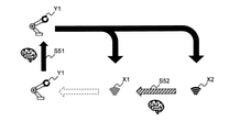
- FIG. 5 is an explanatory diagram showing an example of a design method using the adjustment system of the present embodiment.
- FIG. 5 illustrates a sensor setting method that brings the cost function parameters closer to known sensor characteristics from the ideal movement of the robot arm.
- step S51 the learning device 20 estimates the parameter ⁇ of the cost function of the robot arm Y1 based on the characteristics of the known sensor X1 by machine learning (for example, reverse reinforcement learning). This corresponds to the processing of the first phase described above.
- the black arrow illustrated in FIG. 5 represents the motion achieved with the estimated parameter ⁇ .
- ⁇ corresponds to the parameters directly related to the action plan and the device control logic, such as the level of the camera, millimeter wave, and range finder.
- step S52 the learning device 20 uses machine learning (for example, reverse reinforcement learning) to change the bias ⁇ (range) of the sensor X2. , Level of setting such as measurement interval, etc.). This corresponds to the processing of the second phase described above. As a result, the movement of the unknown sensor X2 is secured as the movement of the known sensor X1.
- machine learning for example, reverse reinforcement learning
- the bias is estimated in the framework of the process for learning the cost function, it is possible to realize the calibration without being aware of the original sensor characteristics. This can be said to be particularly effective in situations where it is necessary to adjust multiple sensors.
- the characteristics of the unknown sensor X2 can be confirmed based on the characteristics of the known sensor X1 and the estimated bias ⁇ in order to confirm the characteristics later. become.
- the output unit 23 outputs the difference between the pre-change cost function and the post-change cost function as an error, so that the user can also confirm the characteristics of the unknown sensor X2.
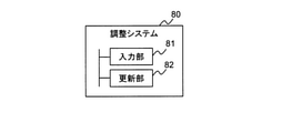
- FIG. 6 is a block diagram showing an outline of the adjustment system according to the present invention.
- the adjustment system 80 according to the present invention was acquired by a device before change (for example, sensor 211, actuator 212, etc.) under control using a first cost function (for example, cost function before change) (for example, an expert).
- a first cost function for example, cost function before change
- an update unit 82 for example, a parameter estimation processing unit 22
- a second cost function for example, a changed cost function
- the update unit 82 estimates the error that occurs in the output value (for example, feature amount) of the device included in the first cost function before and after the change of the device, and updates the first cost function of the second cost function. To generate.
- the update unit 82 sets a variable indicating an error (for example, bias, magnification parameter, etc.) of the output value of the device included in the first cost function, and sets the second cost function (for example, the equation 2 shown above).
- a second cost function may be generated by generating the error and estimating the error by updating the variables so as to reduce the difference between the actual data before the change and the actual data after the change.
- the update unit 82 may generate a second cost function in which the first cost function is updated by reverse reinforcement learning using the actual data before the change and the actual data after the change. With such a configuration, it becomes possible to efficiently estimate the error.
- the update unit 82 repeats the process of updating the second cost function so as to reduce the difference between the decision-making data obtained by optimizing the generated second cost function and the actual data before the change. May be good.
- variable indicating the error of the output value of the device is one or both of the variable indicating the bias (for example, the variable ⁇ shown above) and the variable indicating the magnification parameter (for example, the variable k shown above). May be good.
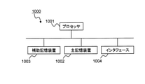
- FIG. 7 is a schematic block diagram showing a configuration of a computer according to at least one embodiment.
- the computer 1000 includes a processor 1001, a main storage device 1002, an auxiliary storage device 1003, and an interface 1004.
- each of the above-mentioned processing units is stored in the auxiliary storage device 1003 in the form of a program (adjustment program).
- the processor 1001 reads a program from the auxiliary storage device 1003, expands it to the main storage device 1002, and executes the above processing according to the program.
- the auxiliary storage device 1003 is an example of a non-temporary tangible medium.
- non-temporary tangible media include magnetic disks, magneto-optical disks, CD-ROMs (Compact Disc Read-only memory), DVD-ROMs (Read-only memory), which are connected via interface 1004. Examples include semiconductor memory.
- the program may be for realizing a part of the above-mentioned functions. Further, the program may be a so-called difference file (difference program) that realizes the above-mentioned function in combination with another program already stored in the auxiliary storage device 1003.
- difference file difference program
- the update unit includes an update unit that generates a second cost function that updates the first cost function so as to reduce the difference between the previous actual data and the changed actual data, and the update unit is a modification of the device.
- An adjustment system characterized in that an error occurring in an output value of the device included in the first cost function is estimated before and after, and a second cost function obtained by updating the first cost function is generated.
- the update unit generates a second cost function in which a variable indicating the error of the output value of the device included in the first cost function is set, and the difference between the actual data before the change and the actual data after the change is calculated.
- the adjustment system according to Appendix 1 which generates a second cost function by updating the variable to make it smaller and estimating the error.
- Appendix 3 The adjustment system according to Appendix 1 or Appendix 2 in which the update unit generates a second cost function in which the first cost function is updated by reverse reinforcement learning using the actual data before and after the change. ..
- the update unit repeats the process of updating the second cost function so as to reduce the difference between the decision-making data obtained by optimizing the generated second cost function and the actual data before the change. 3 The adjustment system described.
- Appendix 5 The adjustment system according to any one of Appendix 2 to Appendix 4, wherein the variable indicating the error of the output value of the device is either one or both of the variable indicating the bias and the variable indicating the magnification parameter. ..
- Appendix 7 Generate a second cost function in which a variable indicating the error of the output value of the device included in the first cost function is set, and reduce the difference between the actual data before the change and the actual data after the change.
- the adjustment method according to Appendix 6 which generates a second cost function by updating the variable and estimating an error.
- Appendix 9 In the update process, the computer is made to generate a second cost function in which a variable indicating the error of the output value of the device included in the first cost function is set, and the actual data before the change and the actual data after the change are generated.
- the program storage medium according to Appendix 8 for storing an adjustment program for generating a second cost function by updating the variable so as to reduce the difference between the two and estimating the error.
Landscapes
- Engineering & Computer Science (AREA)
- Artificial Intelligence (AREA)
- Software Systems (AREA)
- General Physics & Mathematics (AREA)
- Evolutionary Computation (AREA)
- Medical Informatics (AREA)
- Computer Vision & Pattern Recognition (AREA)
- Physics & Mathematics (AREA)
- Health & Medical Sciences (AREA)
- Automation & Control Theory (AREA)
- Robotics (AREA)
- Mechanical Engineering (AREA)
- Theoretical Computer Science (AREA)
- Data Mining & Analysis (AREA)
- Computing Systems (AREA)
- General Engineering & Computer Science (AREA)
- Mathematical Physics (AREA)
- Feedback Control In General (AREA)
Priority Applications (3)
| Application Number | Priority Date | Filing Date | Title |
|---|---|---|---|
| PCT/JP2020/032340 WO2022044191A1 (ja) | 2020-08-27 | 2020-08-27 | 調整システム、調整方法および調整プログラム |
| JP2022544988A JP7416267B2 (ja) | 2020-08-27 | 2020-08-27 | 調整システム、調整方法および調整プログラム |
| US18/023,308 US12547128B2 (en) | 2020-08-27 | 2020-08-27 | Adjustment system, adjustment method, and adjustment program |
Applications Claiming Priority (1)
| Application Number | Priority Date | Filing Date | Title |
|---|---|---|---|
| PCT/JP2020/032340 WO2022044191A1 (ja) | 2020-08-27 | 2020-08-27 | 調整システム、調整方法および調整プログラム |
Publications (1)
| Publication Number | Publication Date |
|---|---|
| WO2022044191A1 true WO2022044191A1 (ja) | 2022-03-03 |
Family
ID=80352885
Family Applications (1)
| Application Number | Title | Priority Date | Filing Date |
|---|---|---|---|
| PCT/JP2020/032340 Ceased WO2022044191A1 (ja) | 2020-08-27 | 2020-08-27 | 調整システム、調整方法および調整プログラム |
Country Status (3)
| Country | Link |
|---|---|
| US (1) | US12547128B2 (https=) |
| JP (1) | JP7416267B2 (https=) |
| WO (1) | WO2022044191A1 (https=) |
Families Citing this family (6)
| Publication number | Priority date | Publication date | Assignee | Title |
|---|---|---|---|---|
| JP7313310B2 (ja) * | 2020-03-31 | 2023-07-24 | 日本碍子株式会社 | セラミックス製の柱状ハニカム構造体の検査方法及び検査装置 |
| US12106051B2 (en) | 2020-07-16 | 2024-10-01 | Optum Technology, Inc. | Unsupervised approach to assignment of pre-defined labels to text documents |
| US11941357B2 (en) * | 2021-06-23 | 2024-03-26 | Optum Technology, Inc. | Machine learning techniques for word-based text similarity determinations |
| US11989240B2 (en) | 2022-06-22 | 2024-05-21 | Optum Services (Ireland) Limited | Natural language processing machine learning frameworks trained using multi-task training routines |
| US12112132B2 (en) | 2022-06-22 | 2024-10-08 | Optum Services (Ireland) Limited | Natural language processing machine learning frameworks trained using multi-task training routines |
| US12367341B2 (en) | 2022-06-22 | 2025-07-22 | Optum Services (Ireland) Limited | Natural language processing machine learning frameworks trained using multi-task training routines |
Citations (1)
| Publication number | Priority date | Publication date | Assignee | Title |
|---|---|---|---|---|
| JP2016522940A (ja) * | 2013-05-08 | 2016-08-04 | ヴィジレント コーポレイションVigilent Corporation | 環境に管理されるシステムにおける影響の学習 |
Family Cites Families (2)
| Publication number | Priority date | Publication date | Assignee | Title |
|---|---|---|---|---|
| US10061316B2 (en) * | 2016-07-08 | 2018-08-28 | Toyota Motor Engineering & Manufacturing North America, Inc. | Control policy learning and vehicle control method based on reinforcement learning without active exploration |
| JP6865152B2 (ja) | 2017-12-15 | 2021-04-28 | 株式会社日立製作所 | 行動履歴を用いた本人認証方法 |
-
2020
- 2020-08-27 WO PCT/JP2020/032340 patent/WO2022044191A1/ja not_active Ceased
- 2020-08-27 JP JP2022544988A patent/JP7416267B2/ja active Active
- 2020-08-27 US US18/023,308 patent/US12547128B2/en active Active
Patent Citations (1)
| Publication number | Priority date | Publication date | Assignee | Title |
|---|---|---|---|---|
| JP2016522940A (ja) * | 2013-05-08 | 2016-08-04 | ヴィジレント コーポレイションVigilent Corporation | 環境に管理されるシステムにおける影響の学習 |
Non-Patent Citations (1)
| Title |
|---|
| ETO RIKI, YASUO SUZUKI, YUKI NAKAGUCHI, DAI KUBOTA, ATSUSHI KASHIWAYA: "Intention learning technology that imitates expert decision making", NEC TECHNICAL JOURNAL, NIPPON DENKI BUNKA SENTA, TOKYO, JP, vol. 72, no. 1, 1 October 2019 (2019-10-01), JP , pages 95 - 98, XP055910107, ISSN: 0285-4139 * |
Also Published As
| Publication number | Publication date |
|---|---|
| US20230333518A1 (en) | 2023-10-19 |
| JPWO2022044191A1 (https=) | 2022-03-03 |
| JP7416267B2 (ja) | 2024-01-17 |
| US12547128B2 (en) | 2026-02-10 |
Similar Documents
| Publication | Publication Date | Title |
|---|---|---|
| JP7416267B2 (ja) | 調整システム、調整方法および調整プログラム | |
| JP6359182B2 (ja) | 機械の動作を制御するための方法およびシステム | |
| Nguyen-Tuong et al. | Local gaussian process regression for real-time model-based robot control | |
| JP6456555B1 (ja) | キャリブレーション装置、キャリブレーション方法および制御装置 | |
| CN108693832B (zh) | 机器学习装置及方法、伺服控制装置、伺服控制系统 | |
| JP2016100009A (ja) | 機械の動作を制御する方法、および機械の動作を反復的に制御する制御システム | |
| CN111670415A (zh) | 用于控制系统的预测控制器、车辆及方法 | |
| Nguyen-Tuong et al. | Learning robot dynamics for computed torque control using local gaussian processes regression | |
| US11619929B2 (en) | Automatic operation control method and system | |
| EP3969671A1 (en) | Control mapping for hydraulic machines | |
| US20220331955A1 (en) | Robotics control system and method for training said robotics control system | |
| CN114690630A (zh) | 神经网络控制器与基于模型的控制器相组合的车辆控制 | |
| CN112986977A (zh) | 一种克服雷达扩展卡尔曼航迹滤波发散的方法 | |
| CN112677147A (zh) | 事件估计系统和事件估计方法 | |
| WO2018143019A1 (ja) | 情報処理装置、情報処理方法およびプログラム記録媒体 | |
| JP7340055B2 (ja) | 強化学習ポリシを訓練する方法 | |
| KR20240172495A (ko) | 객체의 현재 상태를 추정하는 상태 추정 장치 및 방법 | |
| WO2020179299A1 (ja) | 情報処理装置及び情報処理方法 | |
| KR101234797B1 (ko) | 로봇 및 산출된 공분산을 이용한 로봇의 위치 추정 방법 | |
| JP2025520219A (ja) | デバイスの動作を制御するためのシステムおよび方法 | |
| US20260104683A1 (en) | Method for controlling a mechatronic system | |
| CN119247791A (zh) | 水下自航模的高精度航行控制方法、装置、设备及介质 | |
| JP2007183112A (ja) | 目標追尾装置 | |
| JP6984597B2 (ja) | 線形パラメータ変動モデル推定システム、方法およびプログラム | |
| Bendimrad et al. | Optimization of the performances of a two-joint robotic arm using sliding mode control |
Legal Events
| Date | Code | Title | Description |
|---|---|---|---|
| 121 | Ep: the epo has been informed by wipo that ep was designated in this application |
Ref document number: 20951444 Country of ref document: EP Kind code of ref document: A1 |
|
| ENP | Entry into the national phase |
Ref document number: 2022544988 Country of ref document: JP Kind code of ref document: A |
|
| NENP | Non-entry into the national phase |
Ref country code: DE |
|
| 122 | Ep: pct application non-entry in european phase |
Ref document number: 20951444 Country of ref document: EP Kind code of ref document: A1 |
|
| WWG | Wipo information: grant in national office |
Ref document number: 18023308 Country of ref document: US |