WO2022044183A1 - 管渠管理システム、及び調査範囲決定方法 - Google Patents
管渠管理システム、及び調査範囲決定方法 Download PDFInfo
- Publication number
- WO2022044183A1 WO2022044183A1 PCT/JP2020/032297 JP2020032297W WO2022044183A1 WO 2022044183 A1 WO2022044183 A1 WO 2022044183A1 JP 2020032297 W JP2020032297 W JP 2020032297W WO 2022044183 A1 WO2022044183 A1 WO 2022044183A1
- Authority
- WO
- WIPO (PCT)
- Prior art keywords
- information
- pipe
- defect
- acquisition unit
- information acquisition
- Prior art date
- Legal status (The legal status is an assumption and is not a legal conclusion. Google has not performed a legal analysis and makes no representation as to the accuracy of the status listed.)
- Ceased
Links
Images


Classifications
-
- E—FIXED CONSTRUCTIONS
- E03—WATER SUPPLY; SEWERAGE
- E03F—SEWERS; CESSPOOLS
- E03F1/00—Methods, systems, or installations for draining-off sewage or storm water
-
- E—FIXED CONSTRUCTIONS
- E03—WATER SUPPLY; SEWERAGE
- E03F—SEWERS; CESSPOOLS
- E03F7/00—Other installations or implements for operating sewer systems, e.g. for preventing or indicating stoppage; Emptying cesspools
Definitions
- This disclosure relates to a culvert management system.
- Patent Document 1 describes a sensor device installed in an underground pipe and sensing the inside of the pipe, and information obtained as a result of sensing by the sensor device on the ground side.
- a system including a wireless ID tag transmitted to the user and a reader / writer device for receiving a wireless signal transmitted by the wireless ID tag on the ground side is disclosed.
- the present disclosure has been made to solve the above-mentioned problems, and an object of the present disclosure is to provide a technique capable of limiting the scope of investigation for investigating the cause of a defect in a pipe.
- the culvert management system is acquired by the defect information acquisition unit that acquires defect information related to defects in underground culverts, the culvert information acquisition unit that acquires culvert information related to culverts, and the defect information acquisition unit. Scope of investigation to determine the scope of investigation to estimate the location of the cause of the defect in the culvert based on the defect information and the culvert information acquired by the culvert information acquisition unit. Including the decision part.
- FIG. 1 It is a block diagram which shows the structure of the pipe management system which concerns on Embodiment 1. It is a block diagram which shows the detailed structure of the pipe failure analysis apparatus which concerns on Embodiment 1.
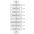
- FIG. It is a flowchart which shows the pipe failure analysis method by the pipe management system which concerns on Embodiment 1.
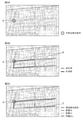
- 4A, 4B, and 4C are diagrams for explaining a method for analyzing a pipe defect by the pipe management system according to the first embodiment, respectively. It is a figure for demonstrating in detail the sewerage ledger used by the culvert management system which concerns on Embodiment 1. It is a figure which shows the traveling route information displayed by the terminal apparatus of the conduit management system which concerns on Embodiment 1.
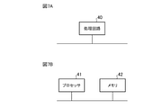
- FIG. 7A is a block diagram showing a hardware configuration that realizes the function of the pipe failure analysis device of the pipe management system according to the first embodiment.
- FIG. 7B is a block diagram showing a hardware configuration for executing software that realizes the function of the pipe failure analysis device of the pipe management system according to the first embodiment.
- FIG. 1 is a block diagram showing a configuration of a drainage management system 100 according to the first embodiment.
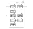
- FIG. 2 is a block diagram showing a detailed configuration of the pipe failure analysis device 10 according to the first embodiment.
- the culvert management system 100 includes a culvert failure analysis server 1, a terminal device 2, a vertical hole lid 3, a vehicle communication device 4, and a power transmission antenna 5.
- the terminal device 2, the vehicle communication device 4, and the power transmission antenna 5 are installed in the vehicle 6.
- the pipe failure analysis server 1 includes a pipe failure analysis device 10 and a storage device 11. As shown in FIG.
- the pipe defect analysis device 10 includes a defect information acquisition unit 20, a pipe information acquisition unit 21, a survey range determination unit 22, a road map information acquisition unit 23, a traveling route information generation unit 24, and a pipe. It includes an internal environment information acquisition unit 25, a cause occurrence location estimation unit 26, and an instruction information generation unit 27.
- the pipe defect analysis device 10 of the pipe defect analysis server 1 has a defect information acquisition unit 20, a pipe information acquisition unit 21, a survey range determination unit 22, a road map information acquisition unit 23, and a traveling route.
- a configuration including an information generation unit 24, an environment information acquisition unit 25 in a pipe, a cause occurrence location estimation unit 26, and an instruction information generation unit 27 will be described.
- the instruction information generation unit 27 may be installed in a device other than the pipe defect analysis server 1, respectively.
- the pipe defect analysis server 1 includes a defect information acquisition unit 20, a pipe information acquisition unit 21, a survey range determination unit 22, a road map information acquisition unit 23, and a travel route information generation unit 24, and the terminal device 2 is a pipe.
- the internal environment information acquisition unit 25, the cause occurrence location estimation unit 26, and the instruction information generation unit 27 may be provided.
- the pipe management system 100 may include at least a defect information acquisition unit 20, a pipe information acquisition unit 21, and a survey range determination unit 22.
- the terminal device 2 receives the defect information regarding the defect in the underground conduit, and transmits the received defect information to the defect information acquisition unit 20 of the conduit defect analysis device 10 of the conduit defect analysis server 1.
- the terminal device 2 is a tablet having a touch panel display. For example, when the passenger of the vehicle 6 inputs the defect information into the terminal device 2, the terminal device 2 receives the defect information.
- the pipe is a sewer.
- the pipe may be, for example, a water supply or a reclaimed water.
- the defect information includes, for example, at least one or more information of the defect occurrence location information regarding the defect occurrence location where the defect has occurred in the pipe, or the defect content information regarding the content of the defect. More specifically, for example, the defect occurrence location information indicates the position of the defect occurrence location of the pipe on the map.
- the defect content information is the rise or fall of the water level in the pipe from the standard water level, the rise from the standard value of the concentration of a specific chemical substance contained in the water in the pipe, and the volatile chemical substance in the pipe.
- the concentration of a certain gas rises from the standard value, the sewage overflows from the manhole connected to the pipe, or the offensive odor from the manhole connected to the pipe.
- the defect content information can be obtained from a complaint from a resident or an inspection of a sewage by a sewage manager.
- the failure information acquisition unit 20 of the pipe defect analysis device 10 of the pipe defect analysis server 1 acquires defect information related to the defect in the underground pipe. More specifically, in the first embodiment, the defect information acquisition unit 20 acquires defect information from the terminal device 2. The defect information acquisition unit 20 outputs the acquired defect information to the investigation range determination unit 22.
- the storage device 11 of the pipe failure analysis server 1 stores the pipe information related to the pipe.
- the storage device 11 outputs the stored pipe information to the pipe information acquisition unit 21 of the pipe failure analysis device 10 of the pipe failure analysis server 1.
- the culvert information includes, for example, culvert map information indicating the position of the culvert, manhole information regarding a manhole connected to the culvert, culvert structure information regarding the structure of the culvert, or running water information regarding running water flowing through the culvert. Contains at least one or more pieces of information.
- An example of culvert information containing such information is a sewerage ledger.
- the pipe information acquisition unit 21 of the pipe defect analysis device 10 of the pipe defect analysis server 1 acquires the pipe information related to the pipe. More specifically, in the first embodiment, the pipe information acquisition unit 21 acquires the pipe information from the storage device 11. The pipe information acquisition unit 21 outputs the acquired pipe information to the investigation range determination unit 22.
- the investigation range determination unit 22 of the pipe defect analysis device 10 of the pipe defect analysis server 1 is based on the defect information acquired by the defect information acquisition unit 20 and the pipe information acquired by the pipe information acquisition unit 21. Determine the scope of investigation to estimate the location of the cause of the failure in the culvert.
- the survey range determination unit 22 outputs the determined survey range to the travel route information generation unit 24.
- the investigation range determined by the investigation range determination unit 22 is a range that may include a cause occurrence location where the cause of the defect has occurred in the pipe.
- the investigation range determined by the investigation range determination unit 22 is a range in which the cause of the trouble may have occurred in the pipe.
- the storage device 11 of the pipe failure analysis server 1 further stores the road map information indicating the road on the ground.
- the storage device 11 outputs the stored road map information to the road map information acquisition unit 23 of the pipe failure analysis device 10 of the pipe failure analysis server 1.
- the road map information is, for example, a digital road map or the like.
- the road map information acquisition unit 23 of the conduit failure analysis device 10 of the conduit failure analysis server 1 acquires road map information indicating a road on the ground. More specifically, in the first embodiment, the road map information acquisition unit 23 acquires the road map information from the storage device 11. The road map information acquisition unit 23 outputs the acquired road map information to the travel route information generation unit 24.
- the travel route information generation unit 24 travels to acquire environmental information in the conduit on the road based on the survey range determined by the survey range determination unit 22 and the road map information acquired by the road map information acquisition unit 23. Generate driving route information about the driving route to be used. The travel route information generation unit 24 outputs the generated travel route information to the terminal device 2.
- the terminal device 2 displays the travel route information generated by the travel route information generation unit 24 as an image.
- the driver of the vehicle 6 drives the vehicle 6 along the travel route indicated by the travel route information displayed by the terminal device 2.
- the terminal device 2 may display, for example, a map showing a road on the ground, and may display the travel route indicated by the travel route information generated by the travel route information generation unit 24 in a specific color on the displayed map. In that case, the terminal device 2 separates the travel route on which the vehicle 6 has traveled and the travel route on which the vehicle 6 has not yet traveled among the travel routes indicated by the travel route information generated by the travel route information generation unit 24. It may be displayed in color.
- the vertical hole lid 3 covers the opening of the vertical hole connecting the above-ground and underground pipes.
- the vertical hole is, in other words, a manhole
- the vertical hole lid 3 is, in other words, a manhole cover.
- the vertical hole lid 3 includes a sensor 30, a transmission unit 31, and a power receiving antenna 32.
- the sensor 30 measures the environment information in the pipe regarding the environment in the pipe.
- the transmission unit 31 is an antenna that transmits the environmental information in the pipe measured by the sensor 30 to the vehicle communication device 4 of the vehicle 6.
- the environmental information in the pipe is, for example, the water level in the pipe, the gas concentration in the pipe, the concentration of a specific chemical substance contained in the water in the pipe, the humidity or temperature in the pipe, and the like.
- the vehicle communication device 4 of the vehicle 6 receives the in-ditch environment information transmitted by the transmission unit 31 of the vertical hole lid 3, and uses the received in-ditch environment information as the pipe defect analysis device 10 of the pipe defect analysis server 1. It is transmitted to the environmental information acquisition unit 25 in the pipe.
- the vehicle communication device 4 when the vehicle 6 travels along the travel route indicated by the travel route information, the vehicle communication device 4 is transmitted by the transmission unit 31 of the vertical hole lid 3 included in the travel route.
- the environment information in the pipe is received, and the received environment information in the pipe is transmitted to the environment information acquisition unit 25 in the pipe.
- the vehicle communication device 4 transmits the in-ditch environment information regarding the environment in the in-ditch of the investigation range determined by the above-mentioned investigation range determination unit 22 to the in-ditch environment information acquisition unit 25.
- the culvert management system 100 includes the road map information acquisition unit 23 and the travel route information generation unit 24, and relates to the environment in the culvert in the survey range based on the travel route information.
- the configuration for acquiring the environmental information in the pipe will be described.
- the pipe management system 100 does not have to include the road map information acquisition unit 23 and the travel route information generation unit 24.
- the terminal device 2 directly displays the survey range determined by the survey range determination unit 22, and the driver of the vehicle 6 drives the vehicle 6 based on the survey range, whereby the vehicle communication device 4 Receives the in-ditch environment information transmitted by the transmission unit 31 of the vertical hole lid 3 included in the investigation range, and transmits the received in-ditch environment information to the in-ditch environment information acquisition unit 25.
- the power transmission antenna 5 of the vehicle 6 transmits power to the power receiving antenna 32 of the vertical hole lid 3 by wireless power transmission.
- the power receiving antenna 32 of the vertical hole lid 3 receives the electric power transmitted by the power transmitting antenna 5 of the vehicle 6 and supplies the received electric power to the sensor 30.
- the sensor 30 uses the electric power as a power source to measure the environment information in the pipe regarding the environment in the pipe.
- the method of wireless power transmission by the transmitting antenna 5 and the receiving antenna 32 is, for example, an electromagnetic induction method, a magnetic field resonance method, an electric field coupling method, a microwave method, or the like.
- the form of the electric power transmitted by the transmitting antenna 5 by wireless power transmission and received by the receiving antenna 32 is, for example, a magnetic flux, a magnetic field, an electric field, an electromagnetic wave, or the like.
- the conduit management system 100 includes the power transmission antenna 5 and the power reception antenna 32, and the power transmission antenna 5 and the power reception antenna 32 perform wireless power transmission.
- the configuration in which the sensor 30 operates by the generated power will be described.
- the conduit management system 100 may not include the power transmission antenna 5 and the power reception antenna 32.
- the vertical hole lid 3 includes a battery, and the sensor 30 measures the environmental information in the pipe using the electric power from the battery as a power source.
- the in-ditch environment information acquisition unit 25 of the in-ditch defect analysis device 10 of the conduit failure analysis server 1 acquires in-ditch environment information regarding the environment in the in-ditch of the investigation range determined by the investigation range determination unit 22. More specifically, in the first embodiment, the in-ditch environment information acquisition unit 25 acquires the in-ditch environment information from the vehicle communication device 4. The in-ditch environment information acquisition unit 25 outputs the acquired in-ditch environment information to the cause occurrence location estimation unit 26.
- the cause occurrence location estimation unit 26 of the pipe defect analysis device 10 of the pipe defect analysis server 1 has generated the cause of the defect based on the in-ditch environment information acquired by the in-ditch environment information acquisition unit 25. Estimate the location of the cause.
- the cause occurrence location estimation unit 26 transmits the estimated cause occurrence location to the terminal device 2. Further, the cause occurrence location estimation unit 26 outputs the estimated cause occurrence location to the instruction information generation unit 27.
- the cause occurrence location estimated by the cause occurrence location 26 is, for example, a clogged location in a pipe, a location in the pipe where sewage containing a specific chemical substance flows in, or a location in which gas which is a volatile chemical substance flows in. And so on.
- the terminal device 2 displays an image of the cause occurrence location estimated by the cause occurrence location estimation unit 26.
- the terminal device 2 displays a map showing a road on the ground, and on the displayed map, the cause occurrence location estimated by the cause occurrence location estimation unit 26 is highlighted by a mark or the like and displayed.
- the instruction information generation unit 27 of the pipe defect analysis device 10 of the pipe defect analysis server 1 responds to the defect indicated by the defect information acquired by the defect information acquisition unit 20 at the cause occurrence location estimated by the cause occurrence location estimation unit 26. Generates instructional information instructing the device to perform an operation. Details will be described later.
- the pipe management system 100 does not have to include the instruction information generation unit 27. In that case, for example, the passenger of the vehicle 6 appropriately responds to the cause occurrence location based on the cause occurrence location displayed by the terminal device 2.
- FIG. 3 is a flowchart showing a pipe failure analysis method by the pipe management system 100 according to the first embodiment. Before each step described below is executed, it is assumed that the terminal device 2 receives the above-mentioned defect information and transmits the accepted defect information to the defect information acquisition unit 20.
- the defect information acquisition unit 20 acquires defect information regarding a defect in an underground pipe from the terminal device 2 (step ST1).
- the defect information acquisition unit 20 outputs the acquired defect information to the investigation range determination unit 22.
- the culvert information acquisition unit 21 acquires culvert information regarding the culvert from the storage device 11 (step ST2).
- the pipe information acquisition unit 21 outputs the acquired pipe information to the investigation range determination unit 22.
- the investigation range determination unit 22 causes a defect in the pipe based on the defect information acquired by the defect information acquisition unit 20 and the pipe information acquired by the pipe information acquisition unit 21.
- the scope of investigation to be investigated in order to estimate the location of the cause is determined (step ST3).
- the survey range determination unit 22 outputs the determined survey range to the travel route information generation unit 24.
- the road map information acquisition unit 23 acquires road map information indicating a road on the ground from the storage device 11 (step ST4).
- the road map information acquisition unit 23 outputs the acquired road map information to the travel route information generation unit 24.
- the travel route information generation unit 24 acquires the environment information in the conduit on the road based on the survey range determined by the survey range determination unit 22 and the road map information acquired by the road map information acquisition unit 23. Generates travel route information regarding the travel route to be traveled for this purpose (step ST5). The travel route information generation unit 24 outputs the generated travel route information to the terminal device 2.
- the terminal device 2 displays the travel route information generated by the travel route information generation unit 24 as an image.
- the driver of the vehicle 6 drives the vehicle 6 along the travel route indicated by the travel route information displayed by the terminal device 2.
- the vehicle communication device 4 receives the in-ditch environment information transmitted by the transmission unit 31 of the vertical hole lid 3 included in the travel route, and transmits the received in-ditch environment information to the in-pipe environment information acquisition unit 25. do.
- the pipe management system 100 may not include the road map information acquisition unit 23 and the travel route information generation unit 24, and may not execute the above steps ST4 and ST5.
- the terminal device 2 directly displays the survey range determined by the survey range determination unit 22, and the driver of the vehicle 6 drives the vehicle 6 based on the survey range, whereby the vehicle communication device 4 Receives the in-ditch environment information transmitted by the transmission unit 31 of the vertical hole lid 3 included in the investigation range, and transmits the received in-ditch environment information to the in-ditch environment information acquisition unit 25.
- the in-ditch environment information acquisition unit 25 acquires in-ditch environment information regarding the environment in the investigation range determined by the investigation range determination unit 22 from the vehicle communication device 4 ( Step ST6).
- the in-ditch environment information acquisition unit 25 outputs the acquired in-ditch environment information to the cause occurrence location estimation unit 26.
- the cause occurrence location estimation unit 26 estimates the cause occurrence location where the cause of the defect has occurred based on the in-ditch environment information acquired by the in-ditch environment information acquisition unit 25 (step ST7).
- the cause occurrence location estimation unit 26 outputs the estimated cause occurrence location to the instruction information generation unit 27.
- the instruction information generation unit 27 gives an instruction to instruct the device according to the defect indicated by the defect information acquired by the defect information acquisition unit 20 to operate at the cause occurrence location estimated by the cause occurrence location estimation unit 26. Generate information (step ST8).
- the drainage management system 100 may not include the instruction information generation unit 27, and may not execute step ST8. In that case, for example, the passenger of the vehicle 6 appropriately responds to the cause occurrence location based on the cause occurrence location displayed by the terminal device 2.
- FIG. 4 is a diagram for explaining a pipe failure analysis method.
- FIG. 4A is a diagram showing a sewerage ledger for explaining the above-mentioned steps ST1 and ST2
- FIG. 4B is a diagram showing a sewerage ledger for explaining each step from the above-mentioned steps ST3 to ST6.
- FIG. 4C is a diagram showing a sewerage ledger for explaining step ST7 and step ST8 described above.
- the defect information acquisition unit 20 receives the defect information from the terminal device 2 as the defect information indicating the defect occurrence location A and the defect content information regarding the content of the defect that occurred in the defect occurrence location A. To get.
- the pipe information acquisition unit 21 acquires the sewerage ledger shown in FIG. 4 as the pipe information from the storage device 11.
- the sewerage ledger includes the above-mentioned culvert map information, manhole information, culvert structure information and running water information.
- FIG. 5 is a diagram for explaining the sewerage ledger in detail.
- the left side of FIG. 5 is a diagram for explaining the manhole information included in the sewerage ledger
- the right side of FIG. 5 is a diagram for explaining the pipe map information, the manhole information, the pipe structure information and the running water information included in the sewerage ledger in detail. It is a figure to do.
- the manhole information acquired by the pipe information acquisition unit 21 indicates the ground height, overburden, manhole depth, manhole number, manhole symbol, and the like.
- the pipe map information acquired by the pipe information acquisition unit 21 includes the manhole position, the positional relationship between manholes, and the positional relationship and connection relationship between the manhole and the pipe. Etc. are shown.
- the culvert map information acquired by the culvert information acquisition unit 21 includes the positional relationship and connection relationship between the culvert and the building pit, and the inflow source of the culvert and a specific chemical substance. The positional relationship and connection relationship of the above shall also be shown.
- the pipe structure information acquired by the pipe information acquisition unit 21 indicates the pipe diameter, pipe thickness, pipe bottom height, extension, slope, and the like of the pipe.
- the flowing water information acquired by the pipe information acquisition unit 21 indicates the direction (arrow) of the flowing water in the pipe.
- the investigation range determination unit 22 manages the pipe based on the defect occurrence location information and the defect content information acquired by the defect information acquisition unit 20 and the sewerage ledger acquired by the drainage information acquisition unit 21. Determine the investigation range B to be investigated in order to estimate the location of the cause of the defect in the culvert.
- the investigation range determination unit 22 determines the pipe. Based on the running water information acquired by the information acquisition unit 21, the range downstream from the defect occurrence location A in the pipe is determined as the investigation range B.
- the investigation range determination unit 22 may determine the flow water information acquired by the pipe information acquisition unit 21.
- the range upstream from the defect occurrence point A in the pipe is determined as the investigation range B.
- the larger the pipe diameter the more the pipe tends not to be clogged. Therefore, the investigation range determination unit 22 is based on the pipe diameter indicated by the pipe structure information acquired by the pipe information acquisition unit 21. Therefore, a range including a pipe having a pipe diameter equal to or larger than a predetermined value may be excluded from the survey range B.
- the investigation range determination unit 22 is based on the running water information acquired by the pipe information acquisition unit 21. , The range upstream from the defect occurrence point A in the pipe is determined as the investigation range B. Further, the survey range determination unit 22 may narrow the survey range B based on the connection point between the pipe and the building pit indicated by the pipe map information acquired by the pipe information acquisition unit 21.
- the investigation range determination unit 22 acquires the pipe information. Based on the running water information acquired by the part 21, the range upstream from the trouble occurrence point A in the pipe is determined as the investigation range B. Further, the survey range determination unit 22 may narrow the survey range B based on the connection point between the pipe and the inflow source of sewage indicated by the pipe map information acquired by the pipe information acquisition unit 21.
- the investigation range determination unit 22 determines the pipe information acquisition unit. Based on the pipe map information acquired by 21, the range around the trouble occurrence point A in the pipe and around the connection point between the pipe and the gas inflow source is determined as the investigation range B.
- step ST4 the road map information acquisition unit 23 acquires road map information indicating a road on the ground from the storage device 11.
- the travel route information generation unit 24 manages the road on the road based on the survey range B determined by the survey range determination unit 22 and the road map information acquired by the road map information acquisition unit 23. Generates driving route information related to the driving route to be traveled in order to acquire the environment information in the culvert.
- the terminal device 2 displays the travel route information generated by the travel route information generation unit 24 as an image.
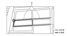
- FIG. 6 is a diagram showing travel route information displayed by the terminal device 2.
- the terminal device 2 has a travel route (measured) on which the vehicle 6 has traveled and a travel route (not yet) on which the vehicle 6 has not yet traveled among the travel routes D indicated by the travel route information generated by the travel route information generation unit 24. (Measurement) is displayed in a different color.
- the vehicle communication device 4 receives the in-ditch environment information transmitted by the transmission unit 31 of the vertical hole lid 3 included in the travel route D. Then, the received environmental information in the pipe is transmitted to the environmental information acquisition unit 25 in the pipe.
- the in-ditch environment information acquisition unit 25 acquires in-ditch environment information regarding the environment in the in-ditch of the investigation range B determined by the investigation range determination unit 22 from the vehicle communication device 4. do.
- the environmental information in the pipe is, for example, the water level in the pipe, the gas concentration in the pipe, the concentration of a specific chemical substance contained in the water in the pipe, and the like.
- the cause occurrence location estimation unit 26 determines the cause occurrence location C in which the cause of the defect has occurred, based on the in-ditch environment information acquired by the in-ditch environment information acquisition unit 25. presume.
- the cause occurrence location estimation unit 26 determines the difference in water level between the two points in the pipe based on the water level in the pipe indicated by the environmental information in the pipe acquired by the environmental information acquisition unit 25 in the pipe. It is presumed that the location larger than the value of is the cause occurrence location C.
- the cause of the malfunction is the inflow of sewage from the building pit connected to the culvert into the culvert
- the concentration of hydrogen sulfide generated from the sewage in the culvert will be in the bill pit, which is the source of hydrogen sulfide. The closer it is, the higher it will be. Therefore, in the cause occurrence location estimation unit 26, the location having the highest concentration of hydrogen sulfide in the conduit indicated by the in-ditch environment information acquired by the in-ditch environment information acquisition unit 25 is the cause occurrence location C. I presume there is.
- the cause occurrence location estimation unit 26 has the highest concentration of the specific chemical substances contained in the water in the pipe, which is indicated by the environmental information in the pipe acquired by the environmental information acquisition unit 25 in the pipe. Is presumed to be the cause occurrence location C.
- the cause occurrence location C is the location having the highest concentration of the gas in the conduit indicated by the in-ditch environment information acquired by the in-ditch environment information acquisition unit 25. I presume.
- the instruction information generation unit 27 operates on the device corresponding to the defect indicated by the defect information acquired by the defect information acquisition unit 20 at the cause occurrence location C estimated by the cause occurrence location estimation unit 26. Generate instructional information instructing you to do.
- the instruction information instructs the equipment installed in the ground to open / close the valve, change the height of the weir or the gate, or clean or remove dust, for example.
- the instruction information generation unit 27 causes when the defect content information of the defect information acquired by the defect information acquisition unit 20 indicates a rise in the water level in the pipe from the standard water level or an overflow of sewage from the manhole connected to the pipe.
- instruction information is generated instructing the heater to perform an operation of raising the temperature in the pipe.
- the temperature inside the culvert rises to about 50 degrees Celsius, and the animal fats and oils are melted to eliminate the clogging in the culvert.
- a water sampler (not shown) is installed in advance at the confluence of drainage from business establishments such as factories in pipes.
- the instruction information generation unit 27 causes the cause.
- instruction information is generated instructing the water sampler to perform an operation of collecting a sample of water in the conduit.
- the weir stop machine is, for example, an electric valve, a gate, a weir, or the like.
- the instruction information generation unit 27 is concerned when the defect content information of the defect information acquired by the defect information acquisition unit 20 indicates a rise in the water level in the pipe from the standard water level or an overflow of sewage from the manhole connected to the pipe. It generates instruction information instructing the dam stop machine to perform an operation of damming the water flowing into the cause occurrence location C estimated by the cause occurrence location estimation unit 26. As a result, for example, the water level at the cause occurrence point C becomes low, and it becomes easy to perform the work for clearing the clogging.
- the pipe defect analysis device 10 of the pipe management system 100 includes a processing circuit for executing the processing of each step shown in FIG. This processing circuit may be dedicated hardware, or may be a CPU (Central Processing Unit) that executes a program stored in the memory.
- This processing circuit may be dedicated hardware, or may be a CPU (Central Processing Unit) that executes a program stored in the memory.
- FIG. 7A is a block diagram showing a hardware configuration that realizes the function of the pipe failure analysis device 10 of the pipe management system 100.
- FIG. 7B is a block diagram showing a hardware configuration for executing software that realizes the function of the pipe failure analysis device 10 of the pipe management system 100.
- the processing circuit 40 may be, for example, a single circuit, a composite circuit, a programmed processor, a parallel programmed processor, or an ASIC (Application Specific Integrated Circuitd). Circuit), FPGA (Field-Programmable Gate Array) or a combination thereof is applicable.
- Failure information acquisition unit 20 pipe information acquisition unit 21, investigation range determination unit 22, road map information acquisition unit 23, travel route information generation unit 24, and pipe inside the pipe failure analysis device 10 of the pipe management system 100.
- the functions of the environment information acquisition unit 25, the cause occurrence location estimation unit 26, and the instruction information generation unit 27 may be realized by separate processing circuits, or these functions may be collectively realized by one processing circuit. ..
- the processing circuit is the processor 41 shown in FIG. 7B, the defect information acquisition unit 20, the conduit information acquisition unit 21, the investigation range determination unit 22, and the road map information in the conduit defect analysis device 10 of the conduit management system 100.
- Each function of the acquisition unit 23, the travel route information generation unit 24, the pipe environment information acquisition unit 25, the cause occurrence location estimation unit 26, and the instruction information generation unit 27 is realized by software, firmware, or a combination of software and firmware.
- the firmware The software or firmware is described as a program and stored in the memory 42.
- the processor 41 By reading and executing the program stored in the memory 42, the processor 41 reads and executes the failure information acquisition unit 20, the pipe information acquisition unit 21, and the investigation range determination unit in the pipe defect analysis device 10 of the pipe management system 100. 22, Each function of the road map information acquisition unit 23, the traveling route information generation unit 24, the in-ditch environment information acquisition unit 25, the cause occurrence location estimation unit 26, and the instruction information generation unit 27 is realized. That is, the culvert failure analysis device 10 of the culvert management system 100 stores a program in which the processing of each step shown in FIG. 3 is executed as a result when each of these functions is executed by the processor 41. A memory 42 for the purpose is provided.
- These programs include a defect information acquisition unit 20, a pipe information acquisition unit 21, a survey range determination unit 22, a road map information acquisition unit 23, and a travel route information generation unit in the pipe defect analysis device 10 of the pipe management system 100.
- the computer is made to execute each procedure or method of the environment information acquisition unit 25 in the pipe, the cause occurrence location estimation unit 26, and the instruction information generation unit 27.
- the memory 42 uses the computer as a defect information acquisition unit 20, a pipe information acquisition unit 21, a survey range determination unit 22, a road map information acquisition unit 23, and a travel route information in the pipe defect analysis device 10 of the pipe management system 100. It may be a computer-readable storage medium in which a program for functioning as a generation unit 24, an environment information acquisition unit 25 in a pipe, a cause occurrence location estimation unit 26, and an instruction information generation unit 27 is stored.
- the processor 41 corresponds to, for example, a CPU (Central Processing Unit), a processing device, a computing device, a processor, a microprocessor, a microcomputer, a DSP (Digital Signal Processor), or the like.
- the memory 42 may include, for example, a RAM (Random Access Memory), a ROM (Read Only Memory), a flash memory, an EPROM (Erasable Programmable Read Only Memory), an EEPROM (Electrically-Volatilizer), or an EEPROM (Electrically-EPROM).
- a RAM Random Access Memory
- ROM Read Only Memory
- flash memory an EPROM (Erasable Programmable Read Only Memory)
- EEPROM Electrically-Volatilizer
- EEPROM Electrically-EPROM
- the trouble information acquisition unit 20 In the pipe defect analysis device 10 of the pipe management system 100, the trouble information acquisition unit 20, the pipe information acquisition unit 21, the investigation range determination unit 22, the road map information acquisition unit 23, the traveling route information generation unit 24, and the pipe inside.
- Some of the functions of the environment information acquisition unit 25, the cause occurrence location estimation unit 26, and the instruction information generation unit 27 may be realized by dedicated hardware, and some may be realized by software or firmware.
- each function of the defect information acquisition unit 20, the pipe information acquisition unit 21, the survey range determination unit 22, the road map information acquisition unit 23, and the travel route information generation unit 24 functions as a processing circuit as dedicated hardware.
- the functions of the in-ditch environment information acquisition unit 25, the cause occurrence location estimation unit 26, and the instruction information generation unit 27 may be realized by the processor 41 reading and executing the program stored in the memory 42.
- the processing circuit can realize each of the above functions by hardware, software, firmware or a combination thereof.
- the culvert management system 100 has a defect information acquisition unit 20 for acquiring defect information regarding a defect in an underground culvert and a culvert information acquisition for acquiring culvert information regarding the culvert. Based on the defect information acquired by the defect information acquisition unit 20 and the conduit information acquired by the conduit information acquisition unit 21, the cause of the defect is estimated in the conduit. Includes a survey scope determination unit 22 that determines the survey scope to be surveyed for the purpose.
- the culvert management system 100 has an in-ditch environment information acquisition unit 25 for acquiring in-ditch environment information regarding the in-ditch environment in the investigation range determined by the investigation range determination unit 22 and a conduit. Further includes a cause occurrence location estimation unit 26 for estimating a cause occurrence location based on the in-ditch environment information acquired by the internal environment information acquisition unit 25.
- the location of the cause can be estimated based on the environment information in the culvert regarding the environment in the culvert in the determined investigation range. That is, it is possible to estimate the location of the cause based on the environment information in the culvert regarding the environment in the culvert in the limited investigation range.
- the defect information acquired by the defect information acquisition unit 20 in the conduit management system 100 according to the first embodiment is the defect occurrence location information regarding the defect occurrence location in the conduit or the defect content regarding the content of the defect. Includes at least one or more pieces of information.
- the culvert information acquired by the culvert information acquisition unit 21 in the culvert management system 100 according to the first embodiment includes culvert map information indicating the position of the culvert, manhole information regarding a manhole connected to the culvert, and culvert information. Includes at least one or more pieces of pipe structure information about the structure or running water information about the running water flowing through the pipe.
- the above configuration in order to estimate the cause occurrence location based on at least one or more information of the pipe map information, the manhole information, the pipe structure information or the running water information. It is possible to determine the scope of investigation to be investigated. This makes it possible to limit the scope of investigation for investigating the cause of a defect in a pipe.
- the conduit management system 100 has a road map information acquisition unit 23 that acquires road map information indicating a road on the ground, a survey range determined by the survey range determination unit 22, and a road map information acquisition unit 23. Further includes a travel route information generation unit 24 that generates travel route information regarding a travel route to be traveled in order to acquire environmental information in the conduit on the road based on the road map information acquired by the road.
- the driving route is appropriately traveled and the environment information in the pipe is acquired, so that the environment information in the pipe is acquired within the limited survey range. Can be done.
- the pipe management system 100 operates at the cause occurrence location estimated by the cause occurrence location estimation unit 26 to the device corresponding to the defect indicated by the defect information acquired by the defect information acquisition unit 20. Further includes an instruction information generation unit 27 that generates instruction information to be instructed. According to the above configuration, by appropriately operating the device based on the generated instruction information, it is possible to take measures according to the defect to the location where the cause occurs.
- the pipe management system 100 is installed in the terminal device 2, the storage device 11, the vertical hole lid 3 covering the opening of the vertical hole connecting the above-ground and underground pipes, and the vehicle 6. Further including the vehicle communication device 4, the terminal device 2 receives the defect information, transmits the received defect information to the defect information acquisition unit 20, and the storage device 11 stores and stores the pipe information.
- the pipe information is transmitted to the pipe information acquisition unit 21, and the vertical hole lid 3 sends the sensor 30 that measures the environment information inside the pipe and the environment information inside the pipe measured by the sensor 30 to the vehicle communication device 4.
- the vehicle communication device 4 includes a transmission unit 31 for transmission, and the vehicle communication device 4 receives the in-ditch environment information transmitted by the transmission unit 31 and transmits the received in-ditch environment information to the in-ditch environment information acquisition unit 25. ..
- the investigation range to be investigated in order to estimate the cause occurrence location based on the defect information obtained from the terminal device 2 and the conduit information obtained from the storage device 11. can.
- This makes it possible to limit the scope of investigation for investigating the cause of a defect in a pipe.
- the location where the cause is generated can be estimated based on the environmental information in the pipe obtained from the vehicle communication device 4. That is, it is possible to estimate the location of the cause based on the environment information in the culvert regarding the environment in the culvert in the limited investigation range.
- the conduit management system 100 further includes a power transmission antenna 5 installed in the vehicle 6, a vertical hole lid 3 further includes a power reception antenna 32, and the power transmission antenna 5 is a radio power transmission.
- the power is transmitted to the power receiving antenna 32, and the power receiving antenna 32 receives the power transmitted by the power transmission antenna 5 and supplies the received power to the sensor 30.
- the sensor 30 it is not necessary to install a battery for supplying electric power to the sensor 30 on the vertical hole lid 3, and the sensor 30 can be operated by the electric power obtained by wireless power transmission.
- the method for determining the investigation range in the pipe defect analysis method is a defect information acquisition step for acquiring defect information regarding a defect in an underground pipe and a pipe information acquisition step for acquiring pipe information regarding the pipe. Based on the defect information acquired in the defect information acquisition step and the conduit information acquired in the conduit information acquisition step, the investigation is conducted to estimate the cause of the defect in the conduit. Includes a survey scope determination step to determine the survey scope to be done. According to the above configuration, it is possible to obtain the same effect as that of the pipe management system 100 according to the first embodiment. It is possible to modify any component of the embodiment or omit any component of the embodiment.
- the culvert management system according to the present disclosure can be used for technology related to culvert management because it can limit the scope of investigation for investigating the cause of a defect in the culvert.
- 1 Ditch defect analysis server 2 Terminal device, 3 Vertical hole lid, 4 Vehicle communication device, 5 Transmission antenna, 6 Vehicle, 10 Ditch defect analysis device, 11 Storage device, 20 Defect information acquisition unit, 21 Ditch information Acquisition unit, 22 Survey range determination unit, 23 Road map information acquisition unit, 24 Driving route information generation unit, 25 Pipeline environment information acquisition unit, 26 Cause occurrence location estimation unit, 27 Instruction information generation unit, 30 Sensor, 31 transmission Department, 32 power receiving antenna, 40 processing circuit, 41 processor, 42 memory, 100 pipe management system.
Landscapes
- Health & Medical Sciences (AREA)
- Life Sciences & Earth Sciences (AREA)
- Engineering & Computer Science (AREA)
- Hydrology & Water Resources (AREA)
- Public Health (AREA)
- Water Supply & Treatment (AREA)
- Sewage (AREA)
Abstract
管渠管理システム(100)は、地下の管渠における不具合に関する不具合情報を取得する不具合情報取得部(20)と、管渠に関する管渠情報を取得する管渠情報取得部(21)と、不具合情報取得部(20)が取得した不具合情報、及び管渠情報取得部(21)が取得した管渠情報に基づいて、管渠における、不具合の原因が発生している原因発生箇所を推定するために調査すべき調査範囲を決定する調査範囲決定部(22)と、を含む。
Description
本開示は、管渠管理システムに関する。
管渠において不具合が生じた場合、当該不具合を調査する必要ある。管渠における不具合を調査する技術として、例えば、特許文献1には、地下の管渠に設置され、管渠内をセンシングするセンサ装置と、当該センサ装置がセンシングした結果得られた情報を地上側に送信するワイヤレスIDタグと、ワイヤレスIDタグが送信した無線信号を地上側で受信するリーダライタ装置とを含むシステムが開示されている。
例えば、上記のようなシステムを用いることにより、地上において管渠内の環境に関する情報を取得することができる。しかし、管渠において、不具合が発生している箇所は、当該不具合の原因が発生している原因発生箇所とは異なる場合がある。その場合、原因発生箇所を特定するために、管渠における、不具合が発生している箇所以外の箇所の環境に関する情報をさらに取得する必要がある。そのためには、例えば、管渠における不具合の原因を調査する人又は車両等が、地上において、当該情報を受信できる場所に移動する必要があり、その調査範囲が広範になるという問題がある。
本開示は、上記のような問題点を解決するためになされたものであり、管渠における不具合の原因を調査する調査範囲を制限することができる技術を提供することを目的とする。
本開示は、上記のような問題点を解決するためになされたものであり、管渠における不具合の原因を調査する調査範囲を制限することができる技術を提供することを目的とする。
本開示に係る管渠管理システムは、地下の管渠における不具合に関する不具合情報を取得する不具合情報取得部と、管渠に関する管渠情報を取得する管渠情報取得部と、不具合情報取得部が取得した不具合情報、及び管渠情報取得部が取得した管渠情報に基づいて、管渠における、不具合の原因が発生している原因発生箇所を推定するために調査すべき調査範囲を決定する調査範囲決定部と、を含む。
本開示によれば、管渠における不具合の原因を調査する調査範囲を制限することができる。
以下、本開示をより詳細に説明するため、本開示を実施するための形態について、添付の図面に従って説明する。
実施の形態1.
図1は、実施の形態1に係る管渠管理システム100の構成を示すブロック図である。図2は、実施の形態1に係る管渠不具合分析装置10の詳細な構成を示すブロック図である。図1が示すように、管渠管理システム100は、管渠不具合分析サーバ1、端末装置2、縦穴用蓋3、車両通信装置4、及び送電用アンテナ5を含む。端末装置2、車両通信装置4及び送電用アンテナ5は、車両6に設置されている。管渠不具合分析サーバ1は、管渠不具合分析装置10、及び記憶装置11を備えている。図2が示すように、管渠不具合分析装置10は、不具合情報取得部20、管渠情報取得部21、調査範囲決定部22、道路地図情報取得部23、走行ルート情報生成部24、管渠内環境情報取得部25、原因発生箇所推定部26、及び指示情報生成部27を備えている。
実施の形態1.
図1は、実施の形態1に係る管渠管理システム100の構成を示すブロック図である。図2は、実施の形態1に係る管渠不具合分析装置10の詳細な構成を示すブロック図である。図1が示すように、管渠管理システム100は、管渠不具合分析サーバ1、端末装置2、縦穴用蓋3、車両通信装置4、及び送電用アンテナ5を含む。端末装置2、車両通信装置4及び送電用アンテナ5は、車両6に設置されている。管渠不具合分析サーバ1は、管渠不具合分析装置10、及び記憶装置11を備えている。図2が示すように、管渠不具合分析装置10は、不具合情報取得部20、管渠情報取得部21、調査範囲決定部22、道路地図情報取得部23、走行ルート情報生成部24、管渠内環境情報取得部25、原因発生箇所推定部26、及び指示情報生成部27を備えている。
なお、実施の形態1では、管渠不具合分析サーバ1の管渠不具合分析装置10が不具合情報取得部20、管渠情報取得部21、調査範囲決定部22、道路地図情報取得部23、走行ルート情報生成部24、管渠内環境情報取得部25、原因発生箇所推定部26及び指示情報生成部27を備えている構成について説明する。しかし、不具合情報取得部20、管渠情報取得部21、調査範囲決定部22、道路地図情報取得部23、走行ルート情報生成部24、管渠内環境情報取得部25、原因発生箇所推定部26及び指示情報生成部27は、それぞれ、管渠不具合分析サーバ1以外の装置に設置されてもよい。例えば、管渠不具合分析サーバ1が不具合情報取得部20、管渠情報取得部21、調査範囲決定部22、道路地図情報取得部23及び走行ルート情報生成部24を備え、端末装置2が管渠内環境情報取得部25、原因発生箇所推定部26及び指示情報生成部27を備えていてもよい。なお、管渠管理システム100は、少なくとも、不具合情報取得部20、管渠情報取得部21、及び調査範囲決定部22含めばよい。
端末装置2は、地下の管渠における不具合に関する不具合情報を受け付け、受け付けた不具合情報を管渠不具合分析サーバ1の管渠不具合分析装置10の不具合情報取得部20に送信する。例えば、端末装置2は、タッチパネルディスプレイを有するタブレットである。例えば、車両6の搭乗者が端末装置2に不具合情報を入力することにより、端末装置2は、不具合情報を受け付ける。
実施の形態1では、管渠は、下水道である。管渠は、例えば、上水道又は中水道等であってもよい。不具合情報は、例えば、管渠における、不具合が発生している不具合発生箇所に関する不具合発生箇所情報、又は不具合の内容に関する不具合内容情報のうちの少なくとも1つ以上の情報を含む。より具体的には、例えば、不具合発生箇所情報は、地図上における、管渠の不具合発生箇所の位置を示す。例えば、不具合内容情報は、管渠における水位の標準水位からの上昇若しくは下降、管渠内の水に含まれる特定の化学物質の濃度の標準値からの上昇、管渠内における揮発性化学物質であるガスの濃度の標準値からの上昇、管渠に繋がるマンホールからの汚水の溢れ、又は管渠に繋がるマンホールからの異臭等である。例えば、不具合内容情報は、住民からの苦情、又は管渠の管理者による管渠の点検等から得られる。
管渠不具合分析サーバ1の管渠不具合分析装置10の不具合情報取得部20は、地下の管渠における不具合に関する不具合情報を取得する。より詳細には、実施の形態1では、不具合情報取得部20は、端末装置2から不具合情報を取得する。不具合情報取得部20は、取得した不具合情報を調査範囲決定部22に出力する。
管渠不具合分析サーバ1の記憶装置11は、管渠に関する管渠情報を記憶している。記憶装置11は、記憶している管渠情報を、管渠不具合分析サーバ1の管渠不具合分析装置10の管渠情報取得部21に出力する。管渠情報は、例えば、管渠の位置を示す管渠地図情報、管渠に接続したマンホールに関するマンホール情報、管渠の構造に関する管渠構造情報、又は、管渠を流れる流水に関する流水情報のうちの少なくとも1つ以上の情報を含む。これらの情報を含む管渠情報の例として、下水道台帳が挙げられる。
管渠不具合分析サーバ1の管渠不具合分析装置10の管渠情報取得部21は、管渠に関する管渠情報を取得する。より詳細には、実施の形態1では、管渠情報取得部21は、記憶装置11から管渠情報を取得する。管渠情報取得部21は、取得した管渠情報を調査範囲決定部22に出力する。
管渠不具合分析サーバ1の管渠不具合分析装置10の調査範囲決定部22は、不具合情報取得部20が取得した不具合情報、及び管渠情報取得部21が取得した管渠情報に基づいて、管渠における、不具合の原因が発生している原因発生箇所を推定するために調査すべき調査範囲を決定する。調査範囲決定部22は、決定した調査範囲を走行ルート情報生成部24に出力する。例えば、調査範囲決定部22が決定する調査範囲は、管渠における、不具合の原因が発生している原因発生箇所を含む可能性がある範囲である。または、例えば、調査範囲決定部22が決定する調査範囲は、管渠における、不具合の原因が発生している可能性がある範囲である。
管渠不具合分析サーバ1の記憶装置11は、地上の道路を示す道路地図情報をさらに記憶している。記憶装置11は、記憶している道路地図情報を、管渠不具合分析サーバ1の管渠不具合分析装置10の道路地図情報取得部23に出力する。道路地図情報は、例えば、デジタルロードマップ等である。
管渠不具合分析サーバ1の管渠不具合分析装置10の道路地図情報取得部23は、地上の道路を示す道路地図情報を取得する。より詳細には、実施の形態1では、道路地図情報取得部23は、記憶装置11から道路地図情報を取得する。道路地図情報取得部23は、取得した道路地図情報を走行ルート情報生成部24に出力する。
走行ルート情報生成部24は、調査範囲決定部22が決定した調査範囲、及び道路地図情報取得部23が取得した道路地図情報に基づいて、道路において、管渠内環境情報を取得するために走行すべき走行ルートに関する走行ルート情報を生成する。走行ルート情報生成部24は、生成した走行ルート情報を端末装置2に出力する。
端末装置2は、走行ルート情報生成部24が生成した走行ルート情報を画像で表示する。車両6の運転者は、端末装置2が表示した走行ルート情報が示す走行ルートに沿って、車両6を走行させる。端末装置2は、例えば、地上の道路を示す地図を表示し、表示した地図において、走行ルート情報生成部24が生成した走行ルート情報が示す走行ルートを特定の色で表示してもよい。その場合、端末装置2は、走行ルート情報生成部24が生成した走行ルート情報が示す走行ルートのうち、車両6が走行した走行ルートと、車両6がまだ走行していない走行ルートとを別の色で表示してもよい。
縦穴用蓋3は、地上と地下の管渠とを繋ぐ縦穴の開口部を覆う。当該縦穴は、換言すればマンホールであり、縦穴用蓋3は、換言すれば、マンホールの蓋である。縦穴用蓋3は、センサ30、送信部31、及び受電用アンテナ32を備えている。センサ30は、管渠内の環境に関する管渠内環境情報を計測する。送信部31は、センサ30が計測した管渠内環境情報を車両6の車両通信装置4に送信するアンテナである。管渠内環境情報は、例えば、管渠内の水位、管渠内のガス濃度、管渠内の水に含まれる特定の化学物質の濃度、又は管渠内の湿度若しくは温度等である。
車両6の車両通信装置4は、縦穴用蓋3の送信部31が送信した管渠内環境情報を受信し、受信した管渠内環境情報を管渠不具合分析サーバ1の管渠不具合分析装置10の管渠内環境情報取得部25に送信する。
つまり、実施の形態1では、車両6が、走行ルート情報が示す走行ルートに沿って走行することにより、車両通信装置4は、当該走行ルートに含まれる縦穴用蓋3の送信部31が送信した管渠内環境情報を受信し、受信した管渠内環境情報を管渠内環境情報取得部25に送信する。結果として、車両通信装置4は、上述の調査範囲決定部22が決定した調査範囲の管渠内の環境に関する管渠内環境情報を管渠内環境情報取得部25に送信する。
なお、実施の形態1では、上記のように、管渠管理システム100が道路地図情報取得部23及び走行ルート情報生成部24を含み、走行ルート情報に基づいて調査範囲の管渠内の環境に関する管渠内環境情報を取得する構成について説明する。しかし、管渠管理システム100は、道路地図情報取得部23及び走行ルート情報生成部24を含まなくてもよい。その場合、例えば、端末装置2は、調査範囲決定部22が決定した調査範囲を直接表示し、車両6の運転者が、当該調査範囲に基づいて車両6を走行させることにより、車両通信装置4は、当該調査範囲に含まれる縦穴用蓋3の送信部31が送信した管渠内環境情報を受信し、受信した管渠内環境情報を管渠内環境情報取得部25に送信する。
車両6の送電用アンテナ5は、無線電力伝送により縦穴用蓋3の受電用アンテナ32に電力を送電する。縦穴用蓋3の受電用アンテナ32は、車両6の送電用アンテナ5が送電した電力を受電し、受電した電力をセンサ30に供給する。センサ30は、当該電力を動力源として、管渠内の環境に関する管渠内環境情報を計測する。送電用アンテナ5及び受電用アンテナ32による無線電力伝送の方式は、例えば、電磁誘導方式、磁界共鳴方式、電界結合方式、又はマイクロ波方式等である。送電用アンテナ5が無線電力伝送により送電し、受電用アンテナ32が受電する電力の形態は、例えば、磁束、磁界、電界、又は電磁波等の形態である。
なお、上記のように、実施の形態1では、管渠管理システム100が送電用アンテナ5及び受電用アンテナ32を含み、送電用アンテナ5と受電用アンテナ32とが無線電力伝送を行うことにより得られた電力によりセンサ30が動作する構成を説明する。しかし、管渠管理システム100は、送電用アンテナ5及び受電用アンテナ32を含まなくてもよい。その場合、例えば、縦穴用蓋3は、バッテリーを備え、センサ30は、バッテリーからの電力を動力源として、管渠内環境情報を計測する。
管渠不具合分析サーバ1の管渠不具合分析装置10の管渠内環境情報取得部25は、調査範囲決定部22が決定した調査範囲の管渠内の環境に関する管渠内環境情報を取得する。より詳細には、実施の形態1では、管渠内環境情報取得部25は、車両通信装置4から当該管渠内環境情報を取得する。管渠内環境情報取得部25は、取得した管渠内環境情報を原因発生箇所推定部26に出力する。
管渠不具合分析サーバ1の管渠不具合分析装置10の原因発生箇所推定部26は、管渠内環境情報取得部25が取得した管渠内環境情報に基づいて、不具合の原因が発生している原因発生箇所を推定する。原因発生箇所推定部26は、推定した原因発生箇所を端末装置2に送信する。また、原因発生箇所推定部26は、推定した原因発生箇所を指示情報生成部27に出力する。原因発生箇所推定部26が推定する原因発生箇所は、例えば、管渠における詰まり箇所、管渠における、特定の化学物質を含む汚水が流入する箇所、又は揮発性化学物質であるガスが流入する箇所等である。
端末装置2は、原因発生箇所推定部26が推定した原因発生箇所を画像で表示する。例えば、端末装置2は、地上の道路を示す地図を表示し、表示した地図において、原因発生箇所推定部26が推定した原因発生箇所をマーク等で強調して表示する。
管渠不具合分析サーバ1の管渠不具合分析装置10の指示情報生成部27は、原因発生箇所推定部26が推定した原因発生箇所において、不具合情報取得部20が取得した不具合情報が示す不具合に応じた機器に動作を行うように指示する指示情報を生成する。詳細については後述する。なお、管渠管理システム100は、指示情報生成部27を含まなくてもよい。その場合、例えば、車両6の搭乗者が、端末装置2が表示した原因発生箇所に基づいて、当該原因発生箇所に対して適宜対応する。
以下で、実施の形態1に係る管渠管理システム100の動作について図面を参照して説明する。図3は、実施の形態1に係る管渠管理システム100による管渠不具合分析方法を示すフローチャートである。なお、以下で説明する各ステップが実行される前に、端末装置2は、上述の不具合情報を受け付け、受け付けた不具合情報を不具合情報取得部20に送信したものとする。
図3が示すように、不具合情報取得部20は、端末装置2から、地下の管渠における不具合に関する不具合情報を取得する(ステップST1)。不具合情報取得部20は、取得した不具合情報を調査範囲決定部22に出力する。
次に、管渠情報取得部21は、記憶装置11から、管渠に関する管渠情報を取得する(ステップST2)。管渠情報取得部21は、取得した管渠情報を調査範囲決定部22に出力する。
次に、管渠情報取得部21は、記憶装置11から、管渠に関する管渠情報を取得する(ステップST2)。管渠情報取得部21は、取得した管渠情報を調査範囲決定部22に出力する。
次に、調査範囲決定部22は、不具合情報取得部20が取得した不具合情報、及び管渠情報取得部21が取得した管渠情報に基づいて、管渠における、不具合の原因が発生している原因発生箇所を推定するために調査すべき調査範囲を決定する(ステップST3)。調査範囲決定部22は、決定した調査範囲を走行ルート情報生成部24に出力する。
次に、道路地図情報取得部23は、記憶装置11から、地上の道路を示す道路地図情報を取得する(ステップST4)。道路地図情報取得部23は、取得した道路地図情報を走行ルート情報生成部24に出力する。
次に、走行ルート情報生成部24は、調査範囲決定部22が決定した調査範囲、及び道路地図情報取得部23が取得した道路地図情報に基づいて、道路において、管渠内環境情報を取得するために走行すべき走行ルートに関する走行ルート情報を生成する(ステップST5)。走行ルート情報生成部24は、生成した走行ルート情報を端末装置2に出力する。
次に、上述のように、端末装置2は、走行ルート情報生成部24が生成した走行ルート情報を画像で表示する。車両6の運転者は、端末装置2が表示した走行ルート情報が示す走行ルートに沿って車両6を走行させる。車両通信装置4は、当該走行ルートに含まれる縦穴用蓋3の送信部31が送信した管渠内環境情報を受信し、受信した管渠内環境情報を管渠内環境情報取得部25に送信する。
なお、上述の通り、管渠管理システム100は、道路地図情報取得部23及び走行ルート情報生成部24を含まなくてもよく、上記のステップST4及びステップST5を実行しなくてもよい。その場合、例えば、端末装置2は、調査範囲決定部22が決定した調査範囲を直接表示し、車両6の運転者が、当該調査範囲に基づいて車両6を走行させることにより、車両通信装置4は、当該調査範囲に含まれる縦穴用蓋3の送信部31が送信した管渠内環境情報を受信し、受信した管渠内環境情報を管渠内環境情報取得部25に送信する。
ステップST5の次のステップとして、管渠内環境情報取得部25は、車両通信装置4から、調査範囲決定部22が決定した調査範囲の管渠内の環境に関する管渠内環境情報を取得する(ステップST6)。管渠内環境情報取得部25は、取得した管渠内環境情報を原因発生箇所推定部26に出力する。
次に、原因発生箇所推定部26は、管渠内環境情報取得部25が取得した管渠内環境情報に基づいて、不具合の原因が発生している原因発生箇所を推定する(ステップST7)。原因発生箇所推定部26は、推定した原因発生箇所を指示情報生成部27に出力する。
次に、指示情報生成部27は、原因発生箇所推定部26が推定した原因発生箇所において、不具合情報取得部20が取得した不具合情報が示す不具合に応じた機器に動作を行うように指示する指示情報を生成する(ステップST8)。なお、上述のように、管渠管理システム100は、指示情報生成部27を含まなくてもよく、ステップST8を実行しなくてもよい。その場合、例えば、車両6の搭乗者が、端末装置2が表示した原因発生箇所に基づいて、当該原因発生箇所に対して適宜対応する。
以下で、実施の形態1に係る管渠管理システム100による管渠不具合分析方法の具体例について図面を参照して説明する。図4は、管渠不具合分析方法を説明するための図である。図4Aは、上述のステップST1及びステップST2を説明するための下水道台帳を示す図であり、図4Bは、上述のステップST3からステップST6までの各ステップを説明するための下水道台帳を示す図であり、図4Cは、上述のステップST7及びステップST8を説明するための下水道台帳を示す図である。
まず、上述のステップST1において、不具合情報取得部20は、端末装置2から、不具合情報として、不具合発生箇所Aを示す不具合発生箇所情報、及び不具合発生箇所Aで発生した不具合の内容に関する不具合内容情報を取得する。
次に、上述のステップST2において、管渠情報取得部21は、記憶装置11から、管渠情報として、図4が示す下水道台帳を取得する。当該下水道台帳は、上述の管渠地図情報、マンホール情報、管渠構造情報及び流水情報を含む。
図5は、下水道台帳を詳細に説明するための図である。図5の左側は、下水道台帳が含むマンホール情報を説明するための図であり、図5の右側は、下水道台帳が含む管渠地図情報、マンホール情報、管渠構造情報及び流水情報を詳細に説明するための図である。図5の左側又は図5の右側が示すように、管渠情報取得部21が取得するマンホール情報は、地盤高、土被り、マンホール深さ、マンホール番号、及びマンホール記号等を示す。図5の左側又は図5の右側が示すように、管渠情報取得部21が取得する管渠地図情報は、マンホール位置、マンホール同士の位置関係、並びにマンホールと管渠との位置関係及び接続関係等を示す。なお、図5には示さないが、管渠情報取得部21が取得する管渠地図情報は、管渠とビルピットとの位置関係及び接続関係、並びに、管渠と特定の化学物質の流入源との位置関係及び接続関係等も示すものとする。図5の左側又は図5の右側が示すように、管渠情報取得部21が取得する管渠構造情報は、管渠の管径、管厚、管底高、延長及び勾配等を示す。図5の右側が示すように、管渠情報取得部21が取得する流水情報は、管渠における流水の流れる方向(矢印)を示す。
次に、上述のステップST3において、調査範囲決定部22は、不具合情報取得部20が取得した不具合発生箇所情報及び不具合内容情報、並びに管渠情報取得部21が取得した下水道台帳に基づいて、管渠における、不具合の原因が発生している原因発生箇所を推定するために調査すべき調査範囲Bを決定する。
例えば、不具合の原因が管渠の詰まりである場合、管渠における詰まった箇所から上流の箇所の水位が下流の箇所の水位よりも高くなる。そのため、調査範囲決定部22は、不具合情報取得部20が取得した不具合内容情報が、管渠における水位の標準水位からの上昇、又は管渠に繋がるマンホールからの汚水の溢れを示す場合、管渠情報取得部21が取得した流水情報に基づいて、管渠における不具合発生箇所Aから下流の範囲を調査範囲Bに決定する。または、調査範囲決定部22は、不具合情報取得部20が取得した不具合内容情報が管渠における水位の標準水位からの下降を示す場合、管渠情報取得部21が取得した流水情報に基づいて、管渠における不具合発生箇所Aから上流の範囲を調査範囲Bに決定する。また、管径が大きければ大きいほど、管渠は、詰まらない傾向があるため、調査範囲決定部22は、管渠情報取得部21が取得した管渠構造情報が示す管渠の管径に基づいて、所定の値以上の管径を有する管渠が含まれる範囲を調査範囲Bから除外してもよい。
例えば、不具合の原因が、管渠に接続するビルピットからの管渠への汚水の流入である場合、当該汚水から発生する硫化水素は、空気より重いため、当該管渠と当該ビルピットとの接続箇所から下流において硫化水素臭がする。そのため、調査範囲決定部22は、不具合情報取得部20が取得した不具合内容情報が、管渠に繋がるマンホールからの硫化水素臭を示す場合、管渠情報取得部21が取得した流水情報に基づいて、管渠における不具合発生箇所Aから上流の範囲を調査範囲Bに決定する。また、調査範囲決定部22は、管渠情報取得部21が取得した管渠地図情報が示す管渠とビルピットとの接続箇所に基づいて、調査範囲Bを絞ってもよい。
例えば、不具合の原因が、特定の化学物質を高濃度に含む汚水の、管渠への流入である場合、当該管渠と当該汚水の流入源との接続箇所から下流において当該特定の化学物質が高濃度で検出される。そのため、調査範囲決定部22は、不具合情報取得部20が取得した不具合内容情報が、管渠内の水に含まれる特定の化学物質の濃度の標準値からの上昇を示す場合、管渠情報取得部21が取得した流水情報に基づいて、管渠における不具合発生箇所Aから上流の範囲を調査範囲Bに決定する。また、調査範囲決定部22は、管渠情報取得部21が取得した管渠地図情報が示す管渠と汚水の流入源との接続箇所に基づいて、調査範囲Bを絞ってもよい。
例えば、不具合の原因が、揮発性化学物質であるガスの管渠への流入である場合、当該管渠と当該ガスの流入源との接続箇所周辺において当該特定の化学物質が高濃度で検出される。そのため、調査範囲決定部22は、不具合情報取得部20が取得した不具合内容情報が、管渠内における揮発性化学物質であるガスの濃度の標準値からの上昇を示す場合、管渠情報取得部21が取得した管渠地図情報に基づいて、管渠における不具合発生箇所A周囲であり且つ管渠とガスの流入源との接続箇所周囲である範囲を調査範囲Bに決定する。
次に、上述のステップST4において、道路地図情報取得部23は、記憶装置11から、地上の道路を示す道路地図情報を取得する。
次に、上述のステップST5において、走行ルート情報生成部24は、調査範囲決定部22が決定した調査範囲B、及び道路地図情報取得部23が取得した道路地図情報に基づいて、道路において、管渠内環境情報を取得するために走行すべき走行ルートに関する走行ルート情報を生成する。端末装置2は、走行ルート情報生成部24が生成した走行ルート情報を画像で表示する。
次に、上述のステップST5において、走行ルート情報生成部24は、調査範囲決定部22が決定した調査範囲B、及び道路地図情報取得部23が取得した道路地図情報に基づいて、道路において、管渠内環境情報を取得するために走行すべき走行ルートに関する走行ルート情報を生成する。端末装置2は、走行ルート情報生成部24が生成した走行ルート情報を画像で表示する。
図6は、端末装置2が表示した走行ルート情報を示す図である。端末装置2は、走行ルート情報生成部24が生成した走行ルート情報が示す走行ルートDのうち、車両6が走行した走行ルート(計測済)と、車両6がまだ走行していない走行ルート(未計測)とを別の色で表示する。車両6が、図6が示す走行ルートDに沿って走行することにより、車両通信装置4は、当該走行ルートDに含まれる縦穴用蓋3の送信部31が送信した管渠内環境情報を受信し、受信した管渠内環境情報を管渠内環境情報取得部25に送信する。
次に、上述のステップST6において、管渠内環境情報取得部25は、車両通信装置4から、調査範囲決定部22が決定した調査範囲Bの管渠内の環境に関する管渠内環境情報を取得する。当該管渠内環境情報は、例えば、管渠内の水位、管渠内のガス濃度、又は管渠内の水に含まれる特定の化学物質の濃度等である。
次に、上述のステップST7において、原因発生箇所推定部26は、管渠内環境情報取得部25が取得した管渠内環境情報に基づいて、不具合の原因が発生している原因発生箇所Cを推定する。
例えば、不具合の原因が管渠の詰まりである場合、管渠における詰まった箇所から上流の範囲において、管渠における水位は、詰まった箇所に近ければ近いほど高くなり、管渠における詰まった箇所から下流の範囲の水位は、管渠における詰まった箇所から上流の範囲の水位よりも低い。そのため、原因発生箇所推定部26は、管渠内環境情報取得部25が取得した管渠内環境情報が示す管渠内の水位に基づいて、管渠内における2点間の水位の差が所定の値よりも大きい箇所が原因発生箇所Cであると推定する。
例えば、不具合の原因が、管渠に接続するビルピットからの管渠への汚水の流入である場合、管渠における、当該汚水から発生する硫化水素の濃度は、硫化水素の発生源であるビルピットに近ければ近いほど高くなる。そのため、原因発生箇所推定部26は、管渠内環境情報取得部25が取得した管渠内環境情報が示す管渠内の硫化水素の濃度のうち最も高い濃度を有する箇所が原因発生箇所Cであると推定する。
例えば、不具合の原因が、特定の化学物質を高濃度に含む汚水の、管渠への流入である場合、管渠内の水に含まれる当該特定の化学物質の濃度は、当該汚水の流入源に近ければ近いほど高くなる。そのため、原因発生箇所推定部26は、管渠内環境情報取得部25が取得した管渠内環境情報が示す管渠内の水に含まれる特定の化学物質の濃度のうち最も高い濃度を有する箇所が原因発生箇所Cであると推定する。
例えば、不具合の原因が、揮発性化学物質であるガスの管渠への流入である場合、管渠におけるガスの濃度は、ガスの流入源に近ければ近いほど高くなる。そのため、原因発生箇所推定部26は、管渠内環境情報取得部25が取得した管渠内環境情報が示す管渠内のガスの濃度のうち最も高い濃度を有する箇所が原因発生箇所Cであると推定する。
次に、上述のステップST8において、指示情報生成部27は、原因発生箇所推定部26が推定した原因発生箇所Cにおいて、不具合情報取得部20が取得した不具合情報が示す不具合に応じた機器に動作を行うように指示する指示情報を生成する。当該指示情報は、例えば、弁の開閉、堰若しくはゲートの高さ変更、又は清掃若しくはゴミ取り等を地中に設置された機器に指示する。
例えば、管渠における詰まりが頻発する箇所にヒータ(図示せず)が予め設置されているものとする。指示情報生成部27は、不具合情報取得部20が取得した不具合情報の不具合内容情報が、管渠における水位の標準水位からの上昇、又は管渠に繋がるマンホールからの汚水の溢れを示す場合、原因発生箇所推定部26が推定した原因発生箇所Cにおいて、当該ヒータに、管渠内の温度を上昇させる動作を行うように指示する指示情報を生成する。これにより、例えば、管渠内の温度が略50度まで上昇し、動物性の油脂を溶かすことによって、管渠における詰まりを解消する。
例えば、管渠における、工場等の事業場からの排水の合流箇所に採水機(図示せず)が予め設置されているものとする。指示情報生成部27は、不具合情報取得部20が取得した不具合情報の不具合内容情報が、管渠内の水に含まれる特定の化学物質の濃度の標準値からの上昇を示す場合、原因発生箇所推定部26が推定した原因発生箇所Cにおいて、当該採水機に、管渠内の水のサンプルを採取する動作を行うように指示する指示情報を生成する。これにより、適宜、管渠の管理者が、当該サンプルに基づいて、特定の化学物質を高濃度に含む汚水の、管渠への流入を解消する。
例えば、管渠における詰まりが頻発する箇所に堰き止め機が予め設置されているものとする。当該堰き止め機は、例えば、電動バルブ、ゲート、又は堰等である。指示情報生成部27は、不具合情報取得部20が取得した不具合情報の不具合内容情報が、管渠における水位の標準水位からの上昇、又は管渠に繋がるマンホールからの汚水の溢れを示す場合、当該堰き止め機に、原因発生箇所推定部26が推定した原因発生箇所Cに流入する水を堰きとめる動作を行うように指示する指示情報を生成する。これにより、例えば、原因発生箇所Cにおける水位が低くなり、詰まりを解消するための作業を行いやすくなる。
管渠管理システム100の管渠不具合分析装置10における、不具合情報取得部20、管渠情報取得部21、調査範囲決定部22、道路地図情報取得部23、走行ルート情報生成部24、管渠内環境情報取得部25、原因発生箇所推定部26及び指示情報生成部27の各機能は、処理回路により実現される。すなわち、管渠管理システム100の管渠不具合分析装置10は、図3に示した各ステップの処理を実行するための処理回路を備える。この処理回路は、専用のハードウェアであってもよいが、メモリに記憶されたプログラムを実行するCPU(Central Processing Unit)であってもよい。
図7Aは、管渠管理システム100の管渠不具合分析装置10の機能を実現するハードウェア構成を示すブロック図である。図7Bは、管渠管理システム100の管渠不具合分析装置10の機能を実現するソフトウェアを実行するハードウェア構成を示すブロック図である。
上記処理回路が図7Aに示す専用のハードウェアの処理回路40である場合、処理回路40は、例えば、単一回路、複合回路、プログラム化したプロセッサ、並列プログラム化したプロセッサ、ASIC(Application Specific Integrated Circuit)、FPGA(Field-Programmable Gate Array)又はこれらを組み合わせたものが該当する。
管渠管理システム100の管渠不具合分析装置10における、不具合情報取得部20、管渠情報取得部21、調査範囲決定部22、道路地図情報取得部23、走行ルート情報生成部24、管渠内環境情報取得部25、原因発生箇所推定部26及び指示情報生成部27の各機能を別々の処理回路で実現してもよいし、これらの機能をまとめて1つの処理回路で実現してもよい。
上記処理回路が図7Bに示すプロセッサ41である場合、管渠管理システム100の管渠不具合分析装置10における、不具合情報取得部20、管渠情報取得部21、調査範囲決定部22、道路地図情報取得部23、走行ルート情報生成部24、管渠内環境情報取得部25、原因発生箇所推定部26及び指示情報生成部27の各機能は、ソフトウェア、ファームウェア又はソフトウェアとファームウェアとの組み合わせによって実現される。
なお、ソフトウェア又はファームウェアは、プログラムとして記述されてメモリ42に記憶される。
なお、ソフトウェア又はファームウェアは、プログラムとして記述されてメモリ42に記憶される。
プロセッサ41は、メモリ42に記憶されたプログラムを読み出して実行することにより、管渠管理システム100の管渠不具合分析装置10における、不具合情報取得部20、管渠情報取得部21、調査範囲決定部22、道路地図情報取得部23、走行ルート情報生成部24、管渠内環境情報取得部25、原因発生箇所推定部26及び指示情報生成部27の各機能を実現する。すなわち、管渠管理システム100の管渠不具合分析装置10は、これらの各機能がプロセッサ41によって実行されるときに、図3に示した各ステップの処理が結果的に実行されるプログラムを記憶するためのメモリ42を備える。
これらのプログラムは、管渠管理システム100の管渠不具合分析装置10における、不具合情報取得部20、管渠情報取得部21、調査範囲決定部22、道路地図情報取得部23、走行ルート情報生成部24、管渠内環境情報取得部25、原因発生箇所推定部26及び指示情報生成部27の各手順又は方法をコンピュータに実行させる。メモリ42は、コンピュータを、管渠管理システム100の管渠不具合分析装置10における、不具合情報取得部20、管渠情報取得部21、調査範囲決定部22、道路地図情報取得部23、走行ルート情報生成部24、管渠内環境情報取得部25、原因発生箇所推定部26及び指示情報生成部27として機能させるためのプログラムが記憶されたコンピュータ可読記憶媒体であってもよい。
プロセッサ41には、例えば、CPU(Central Processing Unit)、処理装置、演算装置、プロセッサ、マイクロプロセッサ、マイクロコンピュータ、またはDSP(Digital Signal Processor)などが該当する。
メモリ42には、例えば、RAM(Random Access Memory)、ROM(Read Only Memory)、フラッシュメモリ、EPROM(Erasable Programmable Read Only Memory)、EEPROM(Electrically-EPROM)などの不揮発性又は揮発性の半導体メモリ、ハードディスク、フレキシブルディスク等の磁気ディスク、フレキシブルディスク、光ディスク、コンパクトディスク、ミニディスク、CD(Compact Disc)、DVD(Digital Versatile Disc)などが該当する。
管渠管理システム100の管渠不具合分析装置10における、不具合情報取得部20、管渠情報取得部21、調査範囲決定部22、道路地図情報取得部23、走行ルート情報生成部24、管渠内環境情報取得部25、原因発生箇所推定部26及び指示情報生成部27の各機能について一部を専用のハードウェアで実現し、一部をソフトウェア又はファームウェアで実現してもよい。
例えば、不具合情報取得部20、管渠情報取得部21、調査範囲決定部22、道路地図情報取得部23及び走行ルート情報生成部24の各機能は、専用のハードウェアとしての処理回路で機能を実現する。管渠内環境情報取得部25、原因発生箇所推定部26及び指示情報生成部27については、プロセッサ41がメモリ42に記憶されたプログラムを読み出して実行することにより機能を実現してもよい。
このように、処理回路は、ハードウェア、ソフトウェア、ファームウェア又はこれらの組み合わせにより上記機能のそれぞれを実現することができる。
このように、処理回路は、ハードウェア、ソフトウェア、ファームウェア又はこれらの組み合わせにより上記機能のそれぞれを実現することができる。
以上のように、実施の形態1に係る管渠管理システム100は、地下の管渠における不具合に関する不具合情報を取得する不具合情報取得部20と、管渠に関する管渠情報を取得する管渠情報取得部21と、不具合情報取得部20が取得した不具合情報、及び管渠情報取得部21が取得した管渠情報に基づいて、管渠における、不具合の原因が発生している原因発生箇所を推定するために調査すべき調査範囲を決定する調査範囲決定部22と、を含む。
上記の構成によれば、不具合情報及び管渠情報に基づいて、原因発生箇所を推定するために調査すべき調査範囲を決定することができる。これにより、管渠における不具合の原因を調査する調査範囲を制限することができる。
実施の形態1に係る管渠管理システム100は、調査範囲決定部22が決定した調査範囲の管渠内の環境に関する管渠内環境情報を取得する管渠内環境情報取得部25と、管渠内環境情報取得部25が取得した管渠内環境情報に基づいて、原因発生箇所を推定する原因発生箇所推定部26と、をさらに含む。
上記の構成によれば、決定した調査範囲の管渠内の環境に関する管渠内環境情報に基づいて、原因発生箇所を推定することができる。つまり、制限された調査範囲の管渠内の環境に関する管渠内環境情報に基づいて、原因発生箇所を推定することができる。
実施の形態1に係る管渠管理システム100における不具合情報取得部20が取得する不具合情報は、管渠における、不具合が発生している不具合発生箇所に関する不具合発生箇所情報、又は不具合の内容に関する不具合内容情報のうちの少なくとも1つ以上の情報を含む。
上記の構成によれば、不具合発生箇所情報及び不具合内容情報のうちの少なくとも1つ以上の情報に基づいて、原因発生箇所を推定するために調査すべき調査範囲を決定することができる。これにより、管渠における不具合の原因を調査する調査範囲を制限することができる。
実施の形態1に係る管渠管理システム100における管渠情報取得部21が取得する管渠情報は、管渠の位置を示す管渠地図情報、管渠に接続したマンホールに関するマンホール情報、管渠の構造に関する管渠構造情報、又は、管渠を流れる流水に関する流水情報のうちの少なくとも1つ以上の情報を含む。
上記の構成によれば、上記の構成によれば、管渠地図情報、マンホール情報、管渠構造情報又は流水情報のうちの少なくとも1つ以上の情報に基づいて、原因発生箇所を推定するために調査すべき調査範囲を決定することができる。これにより、管渠における不具合の原因を調査する調査範囲を制限することができる。
実施の形態1に係る管渠管理システム100は、地上の道路を示す道路地図情報を取得する道路地図情報取得部23と、調査範囲決定部22が決定した調査範囲、及び道路地図情報取得部23が取得した道路地図情報に基づいて、道路において、管渠内環境情報を取得するために走行すべき走行ルートに関する走行ルート情報を生成する走行ルート情報生成部24と、をさらに含む。
上記の構成によれば、生成した走行ルート情報に基づいて、適宜、走行ルートを走行し、管渠内環境情報を取得することによって、制限された調査範囲において管渠内環境情報を取得することができる。
実施の形態1に係る管渠管理システム100は、原因発生箇所推定部26が推定した原因発生箇所において、不具合情報取得部20が取得した不具合情報が示す不具合に応じた機器に動作を行うように指示する指示情報を生成する指示情報生成部27をさらに含む。
上記の構成によれば、生成した指示情報に基づいて、適宜、当該機器を動作させることにより、原因発生箇所に対して、不具合に応じた対応を行うことができる。
上記の構成によれば、生成した指示情報に基づいて、適宜、当該機器を動作させることにより、原因発生箇所に対して、不具合に応じた対応を行うことができる。
実施の形態1に係る管渠管理システム100は、端末装置2と、記憶装置11と、地上と地下の管渠とを繋ぐ縦穴の開口部を覆う縦穴用蓋3と、車両6に設置された車両通信装置4と、をさらに含み、端末装置2は、不具合情報を受け付け、受け付けた不具合情報を不具合情報取得部20に送信し、記憶装置11は、管渠情報を記憶しており、記憶している管渠情報を管渠情報取得部21に送信し、縦穴用蓋3は、管渠内環境情報を計測するセンサ30と、センサ30が計測した管渠内環境情報を車両通信装置4に送信する送信部31と、を備え、車両通信装置4は、送信部31が送信した管渠内環境情報を受信し、受信した管渠内環境情報を管渠内環境情報取得部25に送信する。
上記の構成によれば、端末装置2から得られた不具合情報、及び記憶装置11から得られた管渠情報に基づいて、原因発生箇所を推定するために調査すべき調査範囲を決定することができる。これにより、管渠における不具合の原因を調査する調査範囲を制限することができる。そして、車両通信装置4から得られた管渠内環境情報に基づいて、原因発生箇所を推定することができる。つまり、制限された調査範囲の管渠内の環境に関する管渠内環境情報に基づいて、原因発生箇所を推定することができる。
実施の形態1に係る管渠管理システム100は、車両6に設置された送電用アンテナ5をさらに含み、縦穴用蓋3は、受電用アンテナ32をさらに備え、送電用アンテナ5は、無線電力伝送により受電用アンテナ32に電力を送電し、受電用アンテナ32は、送電用アンテナ5が送電した電力を受電し、受電した電力をセンサ30に供給する。
上記の構成によれば、センサ30に電力を供給するためのバッテリーを縦穴用蓋3に設置する必要がなく、無線電力伝送により得られた電力によってセンサ30を動作させることができる。
実施の形態1に係る管渠不具合分析方法における調査範囲決定方法は、地下の管渠における不具合に関する不具合情報を取得する不具合情報取得ステップと、管渠に関する管渠情報を取得する管渠情報取得ステップと、不具合情報取得ステップで取得した不具合情報、及び管渠情報取得ステップで取得した管渠情報に基づいて、管渠における、不具合の原因が発生している原因発生箇所を推定するために調査すべき調査範囲を決定する調査範囲決定ステップと、を含む。
上記の構成によれば、実施の形態1に係る管渠管理システム100が奏する効果と同様の効果を奏することができる。
なお、実施の形態の任意の構成要素の変形、もしくは実施の形態の任意の構成要素の省略が可能である。
上記の構成によれば、実施の形態1に係る管渠管理システム100が奏する効果と同様の効果を奏することができる。
なお、実施の形態の任意の構成要素の変形、もしくは実施の形態の任意の構成要素の省略が可能である。
本開示に係る管渠管理システムは、管渠における不具合の原因を調査する調査範囲を制限することができるため、管渠の管理に関する技術に利用可能である。
1 管渠不具合分析サーバ、2 端末装置、3 縦穴用蓋、4 車両通信装置、5 送電用アンテナ、6 車両、10 管渠不具合分析装置、11 記憶装置、20 不具合情報取得部、21 管渠情報取得部、22 調査範囲決定部、23 道路地図情報取得部、24 走行ルート情報生成部、25 管渠内環境情報取得部、26 原因発生箇所推定部、27 指示情報生成部、30 センサ、31 送信部、32 受電用アンテナ、40 処理回路、41 プロセッサ、42 メモリ、100 管渠管理システム。
Claims (9)
- 地下の管渠における不具合に関する不具合情報を取得する不具合情報取得部と、
前記管渠に関する管渠情報を取得する管渠情報取得部と、
前記不具合情報取得部が取得した不具合情報、及び前記管渠情報取得部が取得した管渠情報に基づいて、前記管渠における、前記不具合の原因が発生している原因発生箇所を推定するために調査すべき調査範囲を決定する調査範囲決定部と、を含むことを特徴とする、管渠管理システム。 - 前記調査範囲決定部が決定した調査範囲の管渠内の環境に関する管渠内環境情報を取得する管渠内環境情報取得部と、
前記管渠内環境情報取得部が取得した管渠内環境情報に基づいて、前記原因発生箇所を推定する原因発生箇所推定部と、をさらに含むことを特徴とする、請求項1に記載の管渠管理システム。 - 前記不具合情報取得部が取得する不具合情報は、前記管渠における、前記不具合が発生している不具合発生箇所に関する不具合発生箇所情報、又は前記不具合の内容に関する不具合内容情報のうちの少なくとも1つ以上の情報を含むことを特徴とする、請求項1に記載の管渠管理システム。
- 前記管渠情報取得部が取得する管渠情報は、前記管渠の位置を示す管渠地図情報、前記管渠に接続したマンホールに関するマンホール情報、前記管渠の構造に関する管渠構造情報、又は、前記管渠を流れる流水に関する流水情報のうちの少なくとも1つ以上の情報を含むことを特徴とする、請求項1に記載の管渠管理システム。
- 地上の道路を示す道路地図情報を取得する道路地図情報取得部と、
前記調査範囲決定部が決定した調査範囲、及び前記道路地図情報取得部が取得した道路地図情報に基づいて、前記道路において、前記管渠内環境情報を取得するために走行すべき走行ルートに関する走行ルート情報を生成する走行ルート情報生成部と、をさらに含むことを特徴とする、請求項2に記載の管渠管理システム。 - 前記原因発生箇所推定部が推定した原因発生箇所において、前記不具合情報取得部が取得した不具合情報が示す不具合に応じた機器に動作を行うように指示する指示情報を生成する指示情報生成部をさらに含むことを特徴とする、請求項2に記載の管渠管理システム。
- 端末装置と、
記憶装置と、
地上と地下の前記管渠とを繋ぐ縦穴の開口部を覆う縦穴用蓋と、
車両に設置された車両通信装置と、をさらに含み、
前記端末装置は、前記不具合情報を受け付け、受け付けた不具合情報を前記不具合情報取得部に送信し、
前記記憶装置は、前記管渠情報を記憶しており、記憶している管渠情報を前記管渠情報取得部に送信し、
前記縦穴用蓋は、
前記管渠内環境情報を計測するセンサと、
前記センサが計測した管渠内環境情報を前記車両通信装置に送信する送信部と、を備え、
前記車両通信装置は、前記送信部が送信した管渠内環境情報を受信し、受信した管渠内環境情報を前記管渠内環境情報取得部に送信することを特徴とする、請求項2に記載の管渠管理システム。 - 前記車両に設置された送電用アンテナをさらに含み、
前記縦穴用蓋は、受電用アンテナをさらに備え、
前記送電用アンテナは、無線電力伝送により前記受電用アンテナに電力を送電し、
前記受電用アンテナは、前記送電用アンテナが送電した電力を受電し、受電した電力を前記センサに供給することを特徴とする、請求項7に記載の管渠管理システム。 - 地下の管渠における不具合に関する不具合情報を取得する不具合情報取得ステップと、
前記管渠に関する管渠情報を取得する管渠情報取得ステップと、
前記不具合情報取得ステップで取得した不具合情報、及び前記管渠情報取得ステップで取得した管渠情報に基づいて、前記管渠における、前記不具合の原因が発生している原因発生箇所を推定するために調査すべき調査範囲を決定する調査範囲決定ステップと、を含むことを特徴とする、調査範囲決定方法。
Priority Applications (2)
| Application Number | Priority Date | Filing Date | Title |
|---|---|---|---|
| PCT/JP2020/032297 WO2022044183A1 (ja) | 2020-08-27 | 2020-08-27 | 管渠管理システム、及び調査範囲決定方法 |
| JP2020568828A JP6851564B1 (ja) | 2020-08-27 | 2020-08-27 | 管渠管理システム、及び調査範囲決定方法 |
Applications Claiming Priority (1)
| Application Number | Priority Date | Filing Date | Title |
|---|---|---|---|
| PCT/JP2020/032297 WO2022044183A1 (ja) | 2020-08-27 | 2020-08-27 | 管渠管理システム、及び調査範囲決定方法 |
Publications (1)
| Publication Number | Publication Date |
|---|---|
| WO2022044183A1 true WO2022044183A1 (ja) | 2022-03-03 |
Family
ID=75154685
Family Applications (1)
| Application Number | Title | Priority Date | Filing Date |
|---|---|---|---|
| PCT/JP2020/032297 Ceased WO2022044183A1 (ja) | 2020-08-27 | 2020-08-27 | 管渠管理システム、及び調査範囲決定方法 |
Country Status (2)
| Country | Link |
|---|---|
| JP (1) | JP6851564B1 (ja) |
| WO (1) | WO2022044183A1 (ja) |
Citations (3)
| Publication number | Priority date | Publication date | Assignee | Title |
|---|---|---|---|---|
| JP2006183457A (ja) * | 2006-03-02 | 2006-07-13 | Yamaguchi Univ | 下水管損傷予測方法 |
| JP2013231313A (ja) * | 2012-04-28 | 2013-11-14 | Swing Corp | 幹線マンホール緊急時シミュレーションシステム、方法及びプログラム |
| JP2019052521A (ja) * | 2017-09-12 | 2019-04-04 | 管清工業株式会社 | 下水管路の内面腐食個所の推定方法及び腐食個所検出装置 |
-
2020
- 2020-08-27 WO PCT/JP2020/032297 patent/WO2022044183A1/ja not_active Ceased
- 2020-08-27 JP JP2020568828A patent/JP6851564B1/ja active Active
Patent Citations (3)
| Publication number | Priority date | Publication date | Assignee | Title |
|---|---|---|---|---|
| JP2006183457A (ja) * | 2006-03-02 | 2006-07-13 | Yamaguchi Univ | 下水管損傷予測方法 |
| JP2013231313A (ja) * | 2012-04-28 | 2013-11-14 | Swing Corp | 幹線マンホール緊急時シミュレーションシステム、方法及びプログラム |
| JP2019052521A (ja) * | 2017-09-12 | 2019-04-04 | 管清工業株式会社 | 下水管路の内面腐食個所の推定方法及び腐食個所検出装置 |
Also Published As
| Publication number | Publication date |
|---|---|
| JPWO2022044183A1 (ja) | 2022-03-03 |
| JP6851564B1 (ja) | 2021-03-31 |
Similar Documents
| Publication | Publication Date | Title |
|---|---|---|
| CN103912791B (zh) | 地下管网泄漏探测方法 | |
| Naves et al. | Hydraulic, wash-off and sediment transport experiments in a full-scale urban drainage physical model | |
| Beheshti et al. | Detection of extraneous water ingress into the sewer system using tandem methods–a case study in Trondheim city | |
| Follen et al. | Statistical bridge signatures | |
| WO2018138786A1 (ja) | 予兆検知方法、予兆検知システム、及び予兆検知プログラム | |
| Suchowska-Kisielewicz et al. | Influence of storms on the emission of pollutants from sewage into waters | |
| Ouattara et al. | A Review of sewerage and drainage systems typologies with case study in Abidjan, Côte d'Ivoire: failures, policy and management techniques perspectives | |
| US8857256B2 (en) | Micromonitoring apparatus and method | |
| Panasiuk et al. | Identifying sources of infiltration and inflow in sanitary sewers in a northern community: comparative assessment of selected methods | |
| Budai et al. | Development of an autonomous flow-proportional water sampler for the estimation of pollutant loads in urban runoff | |
| JP6851564B1 (ja) | 管渠管理システム、及び調査範囲決定方法 | |
| JP6794899B2 (ja) | 液位測定システム、液位測定方法、及び液位測定プログラム | |
| JP4756092B2 (ja) | 下水道管路における異常水浸入場所の特定のための温度記録方法 | |
| KR100869237B1 (ko) | 폐쇄회로 티브이 영상 또는 회귀분석식을 이용한 하수관거내 퇴적량 예측방법 및 그 기능을 탑재한 하수관거유지관리시스템 | |
| Aguilar et al. | History, mapping, and hydraulic monitoring of a buried stream under a central business district | |
| Chin | Separation of infiltration and inflow in sanitary sewers | |
| Finley et al. | Flood monitoring and mitigation strategies for flood-prone urban areas | |
| Kaur et al. | Reducing the risk of basement flooding through building-and lot-scale flood mitigation approaches: performance of foundation drainage systems | |
| Boogaard et al. | Investigate the condition of an asset | |
| Chen et al. | Performance evaluation of sewer system upgrade in an old residential area in Ningbo, China | |
| JP5842071B1 (ja) | 下水管路の流水検出装置および検出方法 | |
| Verma et al. | On-Site Quality Assurance and Check of Stormwater Drainage Network in the Rural Region of Nagpur, Maharashtra | |
| CN109283308B (zh) | 重力排水管网中定位排放点的测量装置、系统及定位方法 | |
| Meng et al. | Enhancing drainage pipeline inspection: Advanced integration of six-axis sensor fusion and extended Kalman filter | |
| Ahm et al. | Rainfall measurement based on in-situ storm drainage flow sensors |
Legal Events
| Date | Code | Title | Description |
|---|---|---|---|
| ENP | Entry into the national phase |
Ref document number: 2020568828 Country of ref document: JP Kind code of ref document: A |
|
| 121 | Ep: the epo has been informed by wipo that ep was designated in this application |
Ref document number: 20951436 Country of ref document: EP Kind code of ref document: A1 |
|
| NENP | Non-entry into the national phase |
Ref country code: DE |
|
| 122 | Ep: pct application non-entry in european phase |
Ref document number: 20951436 Country of ref document: EP Kind code of ref document: A1 |