WO2022044167A1 - 幹細胞の分化を評価するシステム、方法、及び、プログラム - Google Patents
幹細胞の分化を評価するシステム、方法、及び、プログラム Download PDFInfo
- Publication number
- WO2022044167A1 WO2022044167A1 PCT/JP2020/032191 JP2020032191W WO2022044167A1 WO 2022044167 A1 WO2022044167 A1 WO 2022044167A1 JP 2020032191 W JP2020032191 W JP 2020032191W WO 2022044167 A1 WO2022044167 A1 WO 2022044167A1
- Authority
- WO
- WIPO (PCT)
- Prior art keywords
- differentiation
- information
- cell
- target cell
- failure
- Prior art date
Links
Images


Classifications
-
- G—PHYSICS
- G06—COMPUTING; CALCULATING OR COUNTING
- G06T—IMAGE DATA PROCESSING OR GENERATION, IN GENERAL
- G06T7/00—Image analysis
- G06T7/0002—Inspection of images, e.g. flaw detection
- G06T7/0012—Biomedical image inspection
-
- C—CHEMISTRY; METALLURGY
- C12—BIOCHEMISTRY; BEER; SPIRITS; WINE; VINEGAR; MICROBIOLOGY; ENZYMOLOGY; MUTATION OR GENETIC ENGINEERING
- C12M—APPARATUS FOR ENZYMOLOGY OR MICROBIOLOGY; APPARATUS FOR CULTURING MICROORGANISMS FOR PRODUCING BIOMASS, FOR GROWING CELLS OR FOR OBTAINING FERMENTATION OR METABOLIC PRODUCTS, i.e. BIOREACTORS OR FERMENTERS
- C12M41/00—Means for regulation, monitoring, measurement or control, e.g. flow regulation
- C12M41/30—Means for regulation, monitoring, measurement or control, e.g. flow regulation of concentration
- C12M41/36—Means for regulation, monitoring, measurement or control, e.g. flow regulation of concentration of biomass, e.g. colony counters or by turbidity measurements
-
- C—CHEMISTRY; METALLURGY
- C12—BIOCHEMISTRY; BEER; SPIRITS; WINE; VINEGAR; MICROBIOLOGY; ENZYMOLOGY; MUTATION OR GENETIC ENGINEERING
- C12M—APPARATUS FOR ENZYMOLOGY OR MICROBIOLOGY; APPARATUS FOR CULTURING MICROORGANISMS FOR PRODUCING BIOMASS, FOR GROWING CELLS OR FOR OBTAINING FERMENTATION OR METABOLIC PRODUCTS, i.e. BIOREACTORS OR FERMENTERS
- C12M41/00—Means for regulation, monitoring, measurement or control, e.g. flow regulation
- C12M41/46—Means for regulation, monitoring, measurement or control, e.g. flow regulation of cellular or enzymatic activity or functionality, e.g. cell viability
-
- G—PHYSICS
- G16—INFORMATION AND COMMUNICATION TECHNOLOGY [ICT] SPECIALLY ADAPTED FOR SPECIFIC APPLICATION FIELDS
- G16H—HEALTHCARE INFORMATICS, i.e. INFORMATION AND COMMUNICATION TECHNOLOGY [ICT] SPECIALLY ADAPTED FOR THE HANDLING OR PROCESSING OF MEDICAL OR HEALTHCARE DATA
- G16H30/00—ICT specially adapted for the handling or processing of medical images
- G16H30/40—ICT specially adapted for the handling or processing of medical images for processing medical images, e.g. editing
-
- H—ELECTRICITY
- H04—ELECTRIC COMMUNICATION TECHNIQUE
- H04N—PICTORIAL COMMUNICATION, e.g. TELEVISION
- H04N5/00—Details of television systems
- H04N5/222—Studio circuitry; Studio devices; Studio equipment
- H04N5/262—Studio circuits, e.g. for mixing, switching-over, change of character of image, other special effects ; Cameras specially adapted for the electronic generation of special effects
-
- G—PHYSICS
- G06—COMPUTING; CALCULATING OR COUNTING
- G06T—IMAGE DATA PROCESSING OR GENERATION, IN GENERAL
- G06T2207/00—Indexing scheme for image analysis or image enhancement
- G06T2207/10—Image acquisition modality
- G06T2207/10056—Microscopic image
-
- G—PHYSICS
- G06—COMPUTING; CALCULATING OR COUNTING
- G06T—IMAGE DATA PROCESSING OR GENERATION, IN GENERAL
- G06T2207/00—Indexing scheme for image analysis or image enhancement
- G06T2207/20—Special algorithmic details
- G06T2207/20081—Training; Learning
-
- G—PHYSICS
- G06—COMPUTING; CALCULATING OR COUNTING
- G06T—IMAGE DATA PROCESSING OR GENERATION, IN GENERAL
- G06T2207/00—Indexing scheme for image analysis or image enhancement
- G06T2207/30—Subject of image; Context of image processing
- G06T2207/30004—Biomedical image processing
- G06T2207/30024—Cell structures in vitro; Tissue sections in vitro
Definitions
- the disclosure herein relates to systems, methods, and programs for assessing stem cell differentiation.
- Stem cells which have great potential in applications such as regenerative medicine and disease analysis, have been attracting attention.
- Stem cells are cells having self-renewal ability and differentiation ability, and there are types such as embryonic stem cells (ES cells), induced pluripotent stem cells (iPS cells), and somatic stem cells.
- ES cells embryonic stem cells
- iPS cells induced pluripotent stem cells
- somatic stem cells somatic stem cells.
- iPS cells which can be artificially produced by adding a gene to cells, are attracting particular attention.
- Patent Document 1 proposes a technique for predicting the future state of cells from images of cells in culture.
- iPS cells are prone to individual differences in cells and to be prone to cells with low differentiation potential.
- ES cells it is difficult for ES cells to exhibit the same differentiating ability in a culture vessel (in vitro) as in vivo (in vivo). Therefore, in culturing stem cells, even if the cells are cultured over time and cost to induce cell differentiation, the cells may not differentiate and cells having the desired function may not be obtained, which is time and cost. It often happens that both of them are wasted.
- an object according to one aspect of the present invention is to provide a criterion for determining whether or not cell culture should be continued in cell culture for differentiating stem cells to obtain cells having a desired function. Is to provide the technology to do.
- the system is a system for evaluating the differentiation of stem cells, and is a storage unit that stores a learned model that has learned the success or failure of cell differentiation for a combination of stem cells and a differentiation induction method, and a differentiation induction target.
- An acquisition unit that acquires a target cell image that is an image of a target cell that is a stem cell of the above, and differentiation induction information that is information on a differentiation induction method applied to the target cell, and the target acquired by the acquisition unit.
- an estimation unit Based on the cell image, the differentiation induction information, and the learned model stored in the storage unit, an estimation unit that outputs differentiation success / failure information indicating an estimation result of the differentiation success / failure of the target cell is provided. Be prepared.
- the method according to one aspect of the present invention is a method for evaluating the differentiation of a stem cell, and relates to a target cell image which is an image of a target cell which is a stem cell to be induced to differentiate and a method for inducing differentiation applied to the target cell.
- a target cell image which is an image of a target cell which is a stem cell to be induced to differentiate
- a method for inducing differentiation applied to the target cell Based on the differentiation induction information which is information, the acquired target cell image and the differentiation induction information, and the learned model which learned the success or failure of cell differentiation for the combination of the stem cell and the differentiation induction method. It outputs differentiation success / failure information showing the estimation result of the success / failure of differentiation of the target cell.
- the program according to one aspect of the present invention comprises a computer, a target cell image which is an image of a target cell which is a stem cell to be induced to differentiate, and differentiation induction information which is information about a differentiation induction method applied to the target cell. Based on the acquired target cell image and the differentiation induction information, and a learned model that learned the success or failure of cell differentiation for the combination of stem cells and the differentiation induction method, the success or failure of the differentiation of the target cells was described. The process of outputting the differentiation success / failure information indicating the estimation result is executed.
- FIG. 1 is an example of a flowchart showing a conventional procedure for culturing stem cells.
- a conventional procedure for culturing stem cells will be described before each embodiment of the present invention is described.
- stem cells are first produced (step S1). For example, in the case of producing iPS cells as stem cells, somatic cells are collected, and genes are introduced into the collected somatic cells for reprogramming to produce iPS cells.
- a differentiation inducer is administered to the prepared stem cells (step S2), and the stem cells are observed while continuing the culture of the stem cells (step S3).
- steps S2 and S3 for example, for several days to several weeks, it becomes clear whether or not the differentiation of stem cells has been successful. Then, when it becomes clear that the differentiation has failed (step S4NO), the procedure shown in FIG. 1 is restarted from the beginning.
- step S1 As described above, in the conventional stem cell culturing procedure, all of the procedures shown in FIG. 1 are repeated until the differentiation is successful and the desired amount of cells is obtained. Therefore, unless stem cells having high differentiation potential are stably produced in step S1, the average time required to obtain a desired amount of desired cells is inevitably long.
- the high and low differentiation potentials of the stem cells are discriminated before the induction of differentiation, so that the cell differentiation is unlikely to succeed. Avoid culture.
- stem cells with a high possibility of successful cell differentiation will be cultured, so that even if stem cells with high differentiation potential are not stably produced, a desired amount of desired cells can be obtained.
- the average time required for the cell can be shortened as compared with the conventional case.
- FIG. 2 is a diagram illustrating the configuration of the system 1 according to the present embodiment.
- FIG. 3 is a block diagram illustrating the configuration of the computer 20.
- System 1 is a system for evaluating the differentiation of stem cells having self-renewal potency and differentiation potency. As shown in FIG. 2, the system 1 includes a microscope device 10 for photographing stem cells and a computer 20 for evaluating the differentiation of stem cells.
- the computer 20 applies the image of the stem cells taken by the microscope device 10 and the differentiation induction method to the stem cells. Based on the above, it is estimated in advance whether or not the differentiation of the stem cell will be successful if the culture of the stem cell is continued. As a result, when cell differentiation failure is presumed, it is possible to avoid unnecessary culture by stopping the continuation of cell culture, and as a result, the desired cells can be obtained in a short time and at low cost. It will be possible to obtain.
- the stem cells evaluated by System 1 are, for example, ES cells, iPS cells, and the like.
- the present invention is not limited to pluripotent stem cells such as ES cells and iPS cells, and may be pluripotent stem cells (Multi-potent stem cells).
- the pluripotent stem cell is a stem cell whose direction of differentiation is determined to some extent, and is, for example, a mesenchymal stem cell, which is a typical somatic stem cell.
- Differentiation induction refers to the production of another cell from a stem cell, and the method for inducing differentiation includes at least a stimulus that causes the stem cell to act, that is, a differentiation-inducing factor.
- the differentiation-inducing method may further include a time for the differentiation-inducing factor (stimulation) to act. Further, the differentiation induction method may be a single process or a series of processes performed sequentially.
- the differentiation-inducing factor may be a compound, for example, a humoral factor administered to a culture medium, a gene introduced into a stem cell, or the like. Further, the differentiation-inducing factor may be physical stimulus information, for example, heat, light, electricity, or mechanical stimulus such as pressure or vibration.
- the success or failure of differentiation refers to whether or not the differentiation of a stem cell into another cell is successful, and it does not matter whether or not the differentiated cell has the ability to differentiate. Therefore, for example, differentiation from iPS cells into mesoderm may be interpreted as successful differentiation. In addition, the differentiation of iPS cells into hematopoietic stem cells via mesoderm may be interpreted as successful differentiation. Further, the differentiation of iPS cells into blood cells (platelets, erythrocytes, leukocytes) via mesoderm and hematopoietic stem cells may be interpreted as successful differentiation.
- the microscope device 10 is an example of an imaging unit of the system 1 for photographing a stem cell which is a sample S.
- the microscope device 10 generates an image of a target cell (hereinafter referred to as a target cell image) by photographing a stem cell (also referred to as a target cell) that is a target for differentiation induction. That is, the microscope device 10 photographs the target cell in order to acquire the target cell image.
- the microscope device 10 includes, for example, a digital camera 11, a fluorescent filter cube 12, a turret 13, an objective lens (phase difference objective lens 14, objective lens 15), a stage 16, and a phase difference. It includes a condenser 17 and a light source (light source 18, light source 19).
- the digital camera 11 includes, for example, an image sensor that converts incident observation light into an electric signal.
- the image sensor is, for example, a CCD (Charge Coupled Device) image sensor, a CMOS (Complementary Metal Oxide Sensor) image sensor, or the like, and is a two-dimensional image sensor.
- the digital camera 11 may be a color camera.
- the digital camera 11 captures a sample S, which is a stem cell, and generates a cell image.
- the cell image generated by the digital camera 11 is output from the digital camera 11 to the computer 20.
- the fluorescent filter cube 12 includes, for example, a dichroic mirror, an excitation filter, and an absorption filter.
- the fluorescent filter cube 12 is arranged in the turret 13 and is removable with respect to the optical path.
- the fluorescence filter cube 12 is arranged on the optical path.
- the fluorescence filter cube 12 is arranged outside the optical path.
- the phase difference objective lens 14 and the objective lens 15 are microscope objective lenses mounted on the revolver, and are switched and used according to the observation method.
- the phase difference objective lens 14 is an objective lens used when generating a phase difference image.
- the phase difference objective lens 14 is provided with a phase film for giving a phase difference between the direct light and the diffracted light at the pupil position inside the phase difference objective lens 14.
- the objective lens 15 is an objective lens used when generating a fluorescent image.
- the stage 16 may be an electric stage or a manual stage.
- the phase difference capacitor 17 is a capacitor used when generating a phase difference image.
- the phase difference capacitor 17 is provided with a ring slit at a position optically conjugate with the phase film provided inside the phase difference objective lens 14.
- the light source 18 and the light source 19 are, for example, a mercury lamp, a xenon lamp, an LED light source, and the like.
- the light source 18 and the light source 19 are switched and used according to the observation method.
- the light source 18 is a light source used when generating a phase difference image.
- the light source 18 illuminates the sample S with the light emitted from the light source 18 by using a transmission illumination method.
- the light source 19 is a light source used when generating a fluorescent image.
- the light source 19 illuminates the sample S with the light emitted from the light source 19 by using the epi-illumination method.
- the microscope device 10 can generate both a phase contrast image and a fluorescence image as a cell image. However, considering that the stem cell to be induced to differentiate is subsequently differentiated into other cells and clinically applied, it is desirable that the microscope device 10 photographs the stem cell to be induced to differentiate unstained. Therefore, it is desirable that the microscope device 10 generate a phase contrast image, which is an unstained image obtained by photographing the target cell without staining, as the target cell image. Alternatively, the computer 20 may generate an estimated stained image from the unstained image generated by the microscope device 10 using a trained model that estimates the stained image from the unstained image.
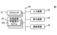
- the computer 20 includes, for example, one or more processors 21, one or more storage devices 22, an input device 23, a display device 24, and a communication device 25. It is connected through bus 26.
- Each of the one or more processors 21 is hardware including, for example, a CPU (Central Processing Unit), a GPU (Graphics Processing Unit), a DSP (Digital Signal Processor), and the like, and is stored in one or more storage devices 22. By executing a program (not shown), the programmed process is performed. Further, the one or more processors 21 may include an ASIC (Application Specific Integrated Circuit), an FPGA (Field-Programmable Gate Array), and the like.
- ASIC Application Specific Integrated Circuit
- FPGA Field-Programmable Gate Array
- One or more processors 21 are an example of the estimation unit of the system 1.
- One or more processors use the learned model 22a stored in the storage device 22 to estimate the success or failure of the differentiation of the target cell, and output the estimation result.
- Each of the one or more storage devices 22 may include, for example, one or more arbitrary semiconductor memories, and may further include one or more other storage devices.
- the semiconductor memory includes, for example, a volatile memory such as a RAM (Random Access Memory), a non-volatile memory such as a ROM (Read Only Memory), a programmable ROM, and a flash memory.
- the RAM may include, for example, a DRAM (Dynamic Random Access Memory), a SRAM (Static Random Access Memory), or the like.
- Other storage devices may include, for example, a magnetic storage device including a magnetic disk, an optical storage device including an optical disk, and the like.
- the one or more storage devices 22 are non-temporary computer-readable media and are an example of the storage unit of the system 1. At least one of the storage devices 22 stores a learned model 22a that has learned the success or failure of cell differentiation for a combination of stem cells and a differentiation-inducing method.
- the input device 23 is a device directly operated by the user, and is, for example, a keyboard, a mouse, a touch panel, or the like.
- the display device 24 is, for example, a liquid crystal display, an organic EL display, a CRT (Cathode Ray Tube) display, or the like.
- the display may have a built-in touch panel.
- the communication device 25 is an example of the notification unit of the system 1.
- the communication device 25 may be a wired communication module or a wireless communication module.
- the input device 23 and the communication device 25 are examples of the acquisition unit of the system 1, and acquire the target cell image and the differentiation induction information.
- Differentiation induction information is information on a differentiation induction method applied to a target cell.
- the differentiation induction information includes information indicating the type of stimulus given to the target cell.
- the differentiation induction information may include information on the timing of giving the stimulus in addition to the information on the type of stimulus. More specifically, it may include information on the differentiation-inducing factor acting on the target cell, for example, information on the differentiation-inducing factor to be administered to the culture medium in which the target cell is immersed, and the timing of the action of the differentiation-inducing factor, for example, differentiation.
- Information on when to administer the inducer to the culture may be included. This is because even if the same differentiation-inducing factor is allowed to act, the success or failure of differentiation and the differentiation destination may differ depending on the timing of action (for example, the 3rd day, the 6th day, etc. from the start of culture).
- the configuration shown in FIG. 3 is an example of the hardware configuration of the computer 20.
- the computer 20 is not limited to this configuration.
- the computer 20 may be a dedicated device instead of a general-purpose device.
- FIG. 4 is an example of a flowchart showing the procedure for culturing stem cells according to this embodiment.
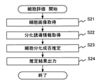
- FIG. 5 is an example of a flowchart of the stem cell evaluation process according to the present embodiment.
- FIG. 6 is a diagram for explaining input / output of the trained model according to the present embodiment.
- the procedure for culturing stem cells performed using the system 1 will be described with reference to FIGS. 4 to 6.
- step S11 the user of the system 1 prepares the stem cells to be induced to differentiate. This process is the same as the process of step S1 in the conventional culture procedure shown in FIG.
- the microscope device 10 photographs the stem cells created in step S11 (step S12).
- the microscope device 10 photographs the stem cells arranged on the stage 16 by using a phase contrast observation method, and generates a target cell image which is a phase contrast image.
- the microscope device 10 outputs the generated target cell image to the computer 20.
- the computer 20 executes the stem cell evaluation process shown in FIG. 5 (step S13).
- the computer 20 first acquires the target cell image generated in step S12 and information (differentiation induction information) regarding the differentiation induction method applied to the stem cells produced in step S11 (step S21, step S22). ..
- the information input by the user using the input device 23 may be acquired as the differentiation induction information.
- the differentiation-inducing information includes, for example, information on the differentiation-inducing factor and information on the timing at which the differentiation-inducing factor acts.
- the timing information may be information that specifies the work start time and period.
- the differentiation induction information may be information that a BMP inhibitor is administered for 12 days and then a TGFbeta / Activin inhibitor is administered for 40 days. Further, as an example of differentiation into chondrocytes, the differentiation induction information may be information that WNT and Activein are administered for 3 days and then BMP4 is administered for 7 days.
- the computer 20 estimates the success or failure of the differentiation of the stem cell produced in step S11 (step S23).
- the computer 20 estimates the success or failure of the differentiation of the stem cells based on the target cell image, the differentiation induction information, and the learned model 22a stored in the storage device 22. More specifically, as shown in FIG. 6, the computer 20 inputs the target cell image and the differentiation induction information into the trained model to estimate the success or failure of the differentiation of the target cell by the trained model. Acquire the differentiation success / failure information shown.
- the differentiation success / failure information may be a binary value of differentiation success and differentiation failure, or may be a probability of differentiation success and a probability of differentiation failure as shown in FIG.
- a step for selecting the trained model to be used may be provided before step S23.
- the operator inputs conditions such as the desired differentiation destination and the type of stem cell into the computer 20 and inputs the desired trained model. You can choose.
- the computer 20 outputs the estimation result in step S23 (step S24).
- the computer 20 outputs the differentiation success / failure information acquired in step S23.
- the differentiation success / failure information may be output to the storage device 22 and recorded in a file or database, or may be output to the display device 24 and displayed as an image.
- cell type information such as the name of the cell or stage after differentiation (for example, the name such as mesoderm or chondrocyte) may be displayed at the same time. ..
- the names of the cells and stages after differentiation may be learned at the same time in the learning procedure described later. As a result, the worker can more reliably determine the success or failure of differentiation of the cells he / she desires.
- step S14 the user determines whether or not the differentiation success is estimated based on the differentiation success / failure information output in step S24 (step S14). If differentiation failure is presumed (step S14NO), the culture of stem cells is stopped at this point, and the procedure shown in FIG. 4 is repeated from the preparation of new stem cells.
- step S14YES when successful differentiation is presumed (step S14YES), the user administers a differentiation-inducing agent (differentiation-inducing factor) to the stem cells (step S15) and observes the stem cells while continuing the culture of the stem cells (step S14 YES).
- step S15 a differentiation-inducing agent
- step S16 The processing of steps S15 and S16 is the same as the processing of steps S2 and S3 in the conventional culture procedure shown in FIG. If it becomes clear that the differentiation of the stem cells has failed after several days to several weeks (step S17NO), the culture of the stem cells is stopped, and the procedure shown in FIG. 4 is repeated from the preparation of new stem cells.
- a stem cell having a low possibility of successful differentiation that is, a stem cell having a low differentiation potential can be identified. It is possible.
- the stem cell differentiation potential estimated by the cell evaluation process as a criterion for determining whether or not to continue the stem cell culture, it is possible to significantly reduce unnecessary culture that fails to differentiate. Therefore, it is possible to reduce the cost of unnecessary culture.
- the culture of unexpected stem cells can be stopped and new stem cells can be produced and evaluated at an early stage, desired cells can be obtained from the stem cells in a shorter time than before.
- desired cells can be obtained from stem cells in a short time and at low cost.
- an undifferentiated cell is targeted as an estimation target instead of a cell that has been differentiated to some extent, it is possible to estimate the success or failure of the culture before proceeding with the culture until the cell differentiates and determine whether to continue the culture.
- the cells to be estimated are preferably cells in an early stage where differentiation and growth have not progressed, considering the cost such as time and labor required for culturing by the operator.
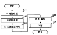
- FIG. 7 is an example of a flowchart showing a learning procedure of the trained model according to the present embodiment.
- FIG. 8 is an example of a flowchart of the learning process according to the present embodiment.
- a learning method of the trained model used for cell evaluation in the system 1 will be described with reference to FIGS. 7 and 8.
- the case where the learning procedure shown in FIGS. 7 and 8 is performed using the system 1 will be described as an example, but the learning procedure shown in FIGS. 7 and 8 is performed using the system 1. It may be performed using a system different from the system 1.
- the user of the system 1 prepares the stem cells to be induced to differentiate (step S31), and then the microscope device 10 photographs the stem cells created in step S21 (step S32).
- the cell image generated in step S32 is, for example, a phase difference image.
- step S33 the user administers a differentiation inducer (differentiation inducer) to the stem cells (step S33), and observes the stem cells while continuing the culture of the stem cells (step S34).
- a differentiation inducer differentiation inducer
- the computer 20 executes the learning process shown in FIG. 8 (step S35).
- the computer 20 first acquires the target cell image, the differentiation induction information, and the differentiation success / failure result information (steps S41 to S43).
- the target cell image is an image generated in step S32.
- the differentiation-inducing information includes information on the differentiation-inducing agent administered in step S33, and the computer 20 acquires, for example, the information input by the user using the input device 23 as the differentiation-inducing information.
- the differentiation success / failure result information is information on the success / failure of differentiation of the stem cells produced in step S31 obtained as a result of the culture / observation in step S34.
- the differentiation success / failure result information may include information on the type and name of the cells after differentiation.
- the computer 20 learns the success or failure of cell differentiation for the combination of stem cells and the differentiation induction method (step S44), and ends the learning process shown in FIGS. 7 and 8.
- the computer 20 trains the machine learning model so as to output the differentiation success / failure result information acquired in step S43 in response to the input of the target cell image acquired in step S41 and the differentiation induction information acquired in step S42.
- FIG. 9 is a diagram illustrating the configuration of the system 2 according to the present embodiment.
- FIG. 10 is a diagram illustrating the configuration of the observation device 30.
- System 2 is a system for evaluating the differentiation of stem cells, similar to system 1.
- the system 2 includes an observation device 30 for photographing stem cells and a computer 20 for evaluating the differentiation of stem cells.
- the system 2 is different from the system 1 in that the observation device 30 is provided instead of the microscope device 10.
- the computer 20 is the same as the computer 20 of the system 1. However, the computer 20 is configured to be able to communicate with a terminal (terminal 50, terminal 60) outside the system 2 registered in advance.
- the terminal 50 and the terminal 60 are, for example, personal terminals of users, and may be mobile phones, smartphones, or the like.
- the observation device 30 is an example of an imaging unit of the system 1 that photographs stem cells (also referred to as target cells) in the culture vessel C.
- the observation device 30 is similar to the microscope device 10 in that the target cell is imaged in order to generate a target cell image.
- the observation device 30 In order to observe the stem cells without removing them from the incubator 40, the observation device 30 is used in a state of being arranged in the incubator 40, for example, as shown in FIG. 9, and the stem cells in culture are photographed. More specifically, the observation device 30 is arranged in the incubator 40 with the culture vessel C placed on the transmission window 31 of the observation device 30, and photographs the stem cells in the culture vessel C according to the instruction from the computer 20. .. By configuring the structure so that the stem cells can be continuously observed without being taken out from the incubator 40, it is possible to prevent contamination due to operations such as opening and closing the incubator 40 and transporting the stem cells.
- the observation device 30 includes a box-shaped housing 32 having a transparent transparent window 31 on which the culture vessel C is arranged as an upper surface.
- the transmission window 31 is a transparent top plate constituting the upper surface of the housing 32 of the observation device 30, and is made of, for example, glass or a transparent resin.
- the observation device 30 further includes a light source unit 34 for illuminating the sample and an imaging unit 35 for acquiring an image of the sample, which are housed inside the housing 32.
- the light source unit 34 and the image pickup unit 35 are installed on the stage 33, and move with respect to the culture vessel C by moving the stage 33 in the housing 32.
- the observation device 30 can illuminate the stem cells existing at an arbitrary position in the culture vessel C by the light source unit 34, and the stem cells can be photographed by the imaging unit 35.
- FIG. 10 shows an example in which the light source unit 34 and the image pickup unit 35 are installed on the stage 33 and, as a result, move together in the housing 32, the light source unit 34 and the image pickup unit are shown. Each of the 35 may move independently in the housing 32.
- the light source unit 34 includes a light source such as a light emitting diode (LED).
- the light source may include a white LED, or may include a plurality of LEDs that emit light having a plurality of different wavelengths, such as R (red), G (green), and B (blue).
- the image pickup unit 35 includes an image pickup element.
- the image sensor is an optical sensor that converts the detected light into an electric signal.
- the image pickup device is specifically an image sensor, and is not particularly limited, and is, for example, a CCD (Challge-Coupled Device) image sensor, a CMOS (Complementary MOS) image sensor, or the like.
- unbalanced illumination is adopted in order to visualize the stem cells in the culture vessel C, which is a phase object.
- the light emitted by the light source unit 34 is emitted to the outside of the housing 32, and then a part of the light emitted to the outside of the housing 32 is reflected by, for example, the upper surface of the culture container C.
- a part of the light deflected above the sample S and further deflected above the sample S is irradiated to the sample S and enters the housing 32 by passing through the sample S and the transmission window 31. do.
- the observation device 30 generates an image of stem cells based on the electric signal output from the image sensor. In this way, the observation device 30 photographs the stem cells without staining, generates a cell image which is a non-staining image that visualizes the stem cells, and outputs the cell image to the computer 20.
- the computer 20 transmits an imaging instruction to the observation device 30 placed in the incubator 40, and receives the cell image generated by the observation device 30 according to the imaging instruction from the observation device 30.
- the computer 20 transmits a shooting instruction to the observation device 30 according to a predetermined schedule, so that the observation device 30 performs time-lapse shooting.
- the time course of the stem cells can be observed without removing the stem cells in culture from the incubator 40.
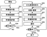
- FIG. 11 is an example of a flowchart showing the procedure for culturing stem cells according to this embodiment.
- FIG. 12 is an example of an application screen displayed on the terminal.
- the procedure for culturing stem cells in time-lapse imaging performed using the system 2 will be described with reference to FIGS. 11 and 12.
- step S51 to step S56 are the same as the processes from steps S11 to S16 of the culturing procedure according to the first embodiment.
- step S58 the microscope device 10 photographs the stem cells produced in step S51 (step S57), and the computer 20 executes the stem cell evaluation process (step S58).
- the processing of steps S57 and S58 is the same as that of steps S52 and S53. That is, in step S58, the computer 20 uses the stem cells (target cells) based on the target cell image and differentiation induction information output from the microscope device 10 by time-lapse imaging and the learned model 22a stored in the storage device 22. ) Differentiation success / failure information is updated at any time.
- the stem cells are continuously photographed even after the differentiation inducer is administered and the differentiation induction is started, and the success or failure of the differentiation of the stem cells is continuously evaluated from the generated cell images. Therefore, although the stem cells themselves have high differentiation potential, it is possible to detect cases where differentiation failure is presumed due to external factors such as the culture environment.
- the computer 20 notifies the terminal registered in advance of the differentiation success / failure information updated in step S58 (step S59).
- the computer 20 may notify the differentiation success / failure information to a terminal outside the system 2, such as a mobile terminal owned by the user (for example, the terminal 50 and the terminal 60 shown in FIG. 9).
- the computer 20 may transmit the cell image generated in step S57 to the user's terminal in addition to the differentiation success / failure information.
- the processes from step S57 to step S59 are repeated until the culture is completed (step S60YES).
- the worker can remotely monitor the differentiation success / failure and the culture status of the stem cells even if he / she is not at the culture site.
- the cell evaluation process shown in FIG. 5 is performed in the same manner as in the system 1 before the initiation of the differentiation induction, so that the stem cells having a low possibility of successful differentiation, that is, differentiation It is possible to distinguish low-potency stem cells. Furthermore, by continuing cell evaluation processing even after the initiation of differentiation induction, it is possible to detect early cases where it is presumed that stem cells with high resolution will fail to differentiate due to late factors such as the culture environment. Can be done. Therefore, according to the system 2, it is possible to further reduce unnecessary cultures that fail to differentiate as compared with the system 1, and it is possible to obtain desired cells from stem cells in a short time and at low cost.
- the computer 20 transmits the differentiation success / failure information to the terminal only when the differentiation success / failure information satisfies a predetermined condition. May be sent to. For example, when the estimation result of differentiation success or failure changes from success to failure, differentiation right / wrong information may be transmitted to the terminal.
- the terminal 60 may display the cell images acquired at different times side by side based on the information from the computer 20, and the transition of the estimated success rate is shown as a graph 61. It may be displayed.
- the trained model 22a (hereinafter, also referred to as the first trained model, if necessary) that has learned the success or failure of cell differentiation for the combination of the stem cells and the differentiation induction method described above.
- a learned model (hereinafter, also referred to as a second learned model, if necessary) that learned the reason for the failure of cell differentiation with respect to the combination of the time course of stem cells and the method for inducing differentiation is stored in the storage device 22. ing. It differs from System 2 in that these trained models are used in the cell evaluation process. Other points are the same as those of the system 2.
- FIG. 13 is a diagram for explaining the input / output of the second trained model.
- the computer 20 in the cell evaluation process of step S58 shown in FIG. 11, the computer 20 is based on a plurality of target cell images taken at different times, differentiation induction information, and a second learned model. , Estimate the reason for the failure of differentiation of target cells. More specifically, as shown in FIG. 13, the computer 20 inputs a plurality of target cell images and differentiation induction information obtained by time-lapse imaging into the second trained model, thereby performing the second learning. Obtain the failure reason information showing the estimation result about the failure reason of the differentiation of the target cell by the completed model.
- the failure reason information may be information indicating a single failure reason, or may be the probability of each of the plurality of failure reasons as shown in FIG.
- the reason for failure when it is presumed that differentiation is successful may be "no reason for failure".
- the reason for the failure of differentiation is presented to the user. Therefore, when differentiation failure is presumed, the culture can be stopped early and the culture of new stem cells can be started. In addition, by presenting the reason for the failure of differentiation, the possibility of repeating the same failure in culturing new stem cells is reduced, so that the probability of failure of differentiation after the start of differentiation induction can be suppressed. Therefore, the system according to the present embodiment also makes it possible to obtain desired cells from stem cells in a short time and at low cost.
- FIG. 14 is an example of a flowchart showing a learning procedure of the trained model according to the present embodiment.
- FIG. 15 is an example of a flowchart of the learning process according to the present embodiment. The learning method of the second trained model among the trained models used for cell evaluation in the system according to the present embodiment will be described with reference to FIGS. 14 and 15.
- step S61 to step S64 are the same as the processes from steps S31 to S34 in the learning process of the first trained model shown in FIG. 7.
- step S66YES the imaging of the stem cells by the microscope device 10 (step S65) and the culture / observation by the user (step S64) are repeated.
- step S67 the computer 20 executes the learning process shown in FIG. 15 (step S67).
- the computer 20 first acquires a plurality of target cell images, differentiation induction information, and failure reason information (steps S71 to S73).
- the plurality of target cell images are the images generated in steps S62 and S65.
- the differentiation-inducing information includes information on the differentiation-inducing agent administered in step S63, and the computer 20 acquires, for example, the information input by the user using the input device 23 as the differentiation-inducing information.
- the failure reason information is information about the reason why the differentiation input by the user using the input device 23 at the end of the culture failed. Specifically, for example, the culture medium is not exchanged properly, the environmental temperature is not set appropriately, and the timing and amount of the differentiation induction information are not appropriate.
- the computer 20 learns the reason for the failure of cell differentiation with respect to the combination of the time course of stem cells and the method for inducing differentiation (step S74), and ends the learning process shown in FIGS. 14 and 15.
- the computer 20 trains the machine learning model so as to output the failure reason information acquired in step S73 with respect to the input of the target cell image acquired in step S71 and the differentiation induction information acquired in step S72.
- the present embodiment is different from the first embodiment and the second embodiment in that the shape of the differentiated cells is estimated in addition to the success or failure of the differentiation of the stem cells using the trained model.
- the shape of the differentiated cell is, more accurately, the shape of the differentiated cell.
- the shape of the cell is not limited to the shape of a single cell, but may be the shape of a colony composed of the cell. That is, the shape of the cells may be an aggregate shape of one or more cells.
- a learned model (hereinafter, also referred to as a third learned model, if necessary) that learned the shape of the cells differentiated from the stem cells with respect to the combination of the stem cells and the differentiation induction method is stored in the storage device 22. There is. It differs from System 1 in that these trained models are used in the cell evaluation process. Other points are the same as those of the system 1.
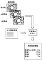
- FIG. 16 is a diagram for explaining the input / output of the third trained model.
- the computer 20 uses the target cell image, the differentiation induction information, and the third learned model to form the shape of the cell differentiated from the target cell.
- the computer 20 differentiated from the target cells according to the third trained model by inputting the target cell image and the differentiation induction information into the third trained model.
- Acquire shape information showing the estimation result about the shape of the cell.
- the shape information may be image information, and may be, for example, image information (cell image) in the same format as the input cell image.
- the shape information may be numerical information such as an internal angle and roundness that can be quantitatively evaluated.
- the shape information may be a combination of image information and numerical information, or both numerical information and image information may be displayed together.
- the system according to the present embodiment in addition to the success or failure of differentiation, the shape of the cells after differentiation is presented to the user. Therefore, it is possible to more specifically recognize the state of cells after differentiation. Therefore, it can be used as an additional judgment material when it is difficult to judge whether or not to continue the culture based on the estimation result of the success or failure of differentiation. Therefore, the system according to the present embodiment also makes it possible to obtain desired cells from stem cells in a short time and at low cost.
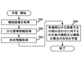
- FIG. 17 is an example of a flowchart of the learning process according to the present embodiment. With reference to FIG. 17, a learning method of a third trained model among the trained models used for cell evaluation in the system according to the present embodiment will be described.
- the learning process of the third trained model is different from the learning process of the first trained model shown in FIG. 7 in that the learning process shown in FIG. 17 is performed instead of the learning process shown in FIG. There is.
- the computer 20 first acquires the target cell image, the differentiation induction information, and the shape information (steps S81 to S83).
- the target cell image is an image generated in step S32 of FIG. 7.
- the differentiation-inducing information includes information on the differentiation-inducing agent administered in step S33, and the computer 20 acquires, for example, the information input by the user using the input device 23 as the differentiation-inducing information.
- the shape information may be, for example, a cell image at the end of the culture, or may be annotation information added by the user to the cell image at the end of the culture.
- the computer 20 learns the shape of the cells differentiated from the stem cells for the combination of the stem cells and the differentiation induction method (step S84), and ends the learning process shown in FIG.
- the computer 20 trains the machine learning model so as to output the shape information acquired in step S83 in response to the input of the target cell image acquired in step S81 and the differentiation induction information acquired in step S82.
- a machine learning model is trained to learn the shape of cells differentiated from stem cells for the combination of stem cells and differentiation induction method.
- the trained model is built.
- a single system including a computer 20 and an imaging device (microscope device 10, observation device 30) is exemplified, but a system for evaluating cell differentiation is, for example, a figure.
- a plurality of independently functioning systems may be connected via a network, or may include a cloud server arranged on the network and accessible from all the systems.
- FIG. 18 is a diagram illustrating the configuration of the system according to the present embodiment.
- the system according to the present embodiment will be referred to as a plurality of systems (system 1, system 2, system 3, system 4, system 5, ... ) And a server 100 that can be accessed from a plurality of subsystems.
- each subsystem is provided, for example, in a business establishment, a laboratory, or the like of a company.
- the server 100 is provided with, for example, a storage device in which the first learning model, the second trained model, and the third trained model described above are stored.
- the server 100 receives the learning data from each subsystem.
- the trained model stored in the storage device of the server 100 is a trained model trained using various training data received from all the subsystems, whereas it is stored in the storage device of each subsystem.
- the trained model is a trained model trained using the training data obtained in each subsystem.
- the stem cells and differentiation induction methods used in the specific establishments and laboratories where the subsystems are located are similar. Therefore, in each subsystem, it is possible to estimate the stem cells and differentiation induction methods that are normally used with high accuracy by using the trained model.
- the server 100 since learning is performed using various learning data, a highly versatile trained model is constructed, and it is possible to deal with various combinations of stem cells and differentiation induction methods. For certain combinations, the estimation accuracy may be inferior to that of the subsystem.
- each subsystem makes an estimation using the learned model in the subsystem for the combination of the already learned stem cells and the differentiation induction method, and for the unknown combination, the server 100 is used. Entrust cell evaluation. By doing so, it is possible to estimate with a certain degree of accuracy or higher for any combination while performing high-precision estimation for the combinations that are usually used.
- each embodiment can modify the components within a range that does not deviate from the purpose and scope.
- a new embodiment can be implemented by appropriately combining a plurality of components disclosed in one or more embodiments.
- some components may be deleted from the components shown in each embodiment, or some components may be added to the components shown in the embodiments.
- the processing procedures shown in each embodiment may be performed in a different order as long as there is no contradiction. That is, the system, method, and program for evaluating the differentiation of stem cells of the present invention can be variously modified and modified without departing from the description of the claims.
- the expression “based on A” does not mean “based solely on A”, but means “at least based on A” and further “at least partially based on A”. It also means “te”. That is, “based on A” may be based on B in addition to A, or may be based on a part of A.
- first and second that modify a noun do not limit the amount or order of the elements expressed by the noun. These terms are used to distinguish between two or more elements, no less, no more. Therefore, the identification of the "first” and “second” elements does not mean that the “first” element precedes the “second” element, nor does it mean that the "second” element precedes it. It does not deny the existence of the "element” of 3.
Landscapes
- Engineering & Computer Science (AREA)
- Health & Medical Sciences (AREA)
- Chemical & Material Sciences (AREA)
- Life Sciences & Earth Sciences (AREA)
- Wood Science & Technology (AREA)
- Organic Chemistry (AREA)
- Bioinformatics & Cheminformatics (AREA)
- General Health & Medical Sciences (AREA)
- Zoology (AREA)
- Microbiology (AREA)
- Radiology & Medical Imaging (AREA)
- Biotechnology (AREA)
- Biochemistry (AREA)
- General Engineering & Computer Science (AREA)
- Biomedical Technology (AREA)
- Genetics & Genomics (AREA)
- Analytical Chemistry (AREA)
- Sustainable Development (AREA)
- Nuclear Medicine, Radiotherapy & Molecular Imaging (AREA)
- Medical Informatics (AREA)
- General Physics & Mathematics (AREA)
- Cell Biology (AREA)
- Multimedia (AREA)
- Quality & Reliability (AREA)
- Computer Vision & Pattern Recognition (AREA)
- Physics & Mathematics (AREA)
- Signal Processing (AREA)
- Theoretical Computer Science (AREA)
- Public Health (AREA)
- Primary Health Care (AREA)
- Epidemiology (AREA)
- Apparatus Associated With Microorganisms And Enzymes (AREA)
- Micro-Organisms Or Cultivation Processes Thereof (AREA)
- Measuring Or Testing Involving Enzymes Or Micro-Organisms (AREA)
Abstract
幹細胞の分化を評価するシステムは、幹細胞と分化誘導方法との組み合わせに対する細胞分化の成否を学習した学習済みモデルを記憶する記憶部と、分化誘導対象の幹細胞である対象細胞の画像である対象細胞画像と、対象細胞に適用される分化誘導方法に関する情報である分化誘導情報と、を取得する取得部と、取得部で取得された対象細胞画像及び分化誘導情報と、記憶部に記憶されている学習済みモデルとに基づいて、対象細胞の分化の成否についての推定結果を示す分化成否情報を出力する推定部と、を備える。
Description
本明細書の開示は、幹細胞の分化を評価するシステム、方法、及び、プログラムに関する。
近年、再生医療や疾患解析などの用途において大きな可能性を有する幹細胞が注目されている。幹細胞は自己複製能と分化能とを有する細胞であり、胚性幹細胞(ES細胞)、人工多能性幹細胞(iPS細胞)、体性幹細胞などの種類が存在する。それらの中でも、細胞に遺伝子を加えることにより人工的に作製可能なiPS細胞には、特に大きな注目が集まっている。
幹細胞を含む細胞の培養に関する技術は様々提案されている。例えば、特許文献1には、培養中の細胞の画像から将来の細胞の状態を予測する技術が提案されている。
ところで、人工的に作製されるiPS細胞は、細胞に個体差が生じやすく、分化能の低い細胞が生じやすいことが知られている。また、ES細胞についても、培養容器内(in vitro)では、生体内(in vivo)と同様の分化能を発揮することは難しい。このため、幹細胞の培養では、時間とコストをかけて細胞を培養し細胞の分化を誘導したとしても、細胞が分化せず望んだ機能を有する細胞を得ることができないことがあり、時間とコストの両方が無駄になってしまうといった事態が度々生じている。
以上のような実情から、本発明の一側面に係る目的は、幹細胞を分化させて所望の機能を有する細胞を得るための細胞培養において、細胞の培養を継続すべきか否かの判断基準を提供する技術を提供することである。
本発明の一態様に係るシステムは、幹細胞の分化を評価するシステムであって、幹細胞と分化誘導方法との組み合わせに対する細胞分化の成否を学習した学習済みモデルを記憶する記憶部と、分化誘導対象の幹細胞である対象細胞の画像である対象細胞画像と、前記対象細胞に適用される分化誘導方法に関する情報である分化誘導情報と、を取得する取得部と、前記取得部で取得された前記対象細胞画像及び前記分化誘導情報と、前記記憶部に記憶されている前記学習済みモデルとに基づいて、前記対象細胞の分化の成否についての推定結果を示す分化成否情報を出力する推定部と、を備える。
本発明の一態様に係る方法は、幹細胞の分化を評価する方法であって、分化誘導対象の幹細胞である対象細胞の画像である対象細胞画像と、前記対象細胞に適用される分化誘導方法に関する情報である分化誘導情報と、を取得し、取得した前記対象細胞画像及び前記分化誘導情報と、幹細胞と分化誘導方法との組み合わせに対する細胞分化の成否を学習した学習済みモデルとに基づいて、前記対象細胞の分化の成否についての推定結果を示す分化成否情報を出力する。
本発明の一態様に係るプログラムは、コンピュータに、分化誘導対象の幹細胞である対象細胞の画像である対象細胞画像と、前記対象細胞に適用される分化誘導方法に関する情報である分化誘導情報と、を取得し、取得した前記対象細胞画像及び前記分化誘導情報と、幹細胞と分化誘導方法との組み合わせに対する細胞分化の成否を学習した学習済みモデルとに基づいて、前記対象細胞の分化の成否についての推定結果を示す分化成否情報を出力する処理を実行させる。
上記の態様によれば、幹細胞を分化させて所望の機能を有する細胞を得るための細胞培養において、細胞の培養を継続すべきか否かの判断基準を提供することができる。
図1は、従来における幹細胞の培養手順を示したフローチャートの一例である。本発明の理解を容易にするために、本発明の各実施形態について説明する前に、従来における幹細胞の培養手順について説明する。
図1に示すように、所望の細胞を得るための従来の幹細胞の培養手順では、まず最初に幹細胞が作製される(ステップS1)。例えば、幹細胞としてiPS細胞を作製する場合であれば、体細胞を採取し、採取した体細胞に遺伝子を導入して初期化することで、iPS細胞を作製する。
その後、作製した幹細胞に分化誘導剤を投与し(ステップS2)、幹細胞の培養を継続しながら幹細胞を観察する(ステップS3)。ステップS2及びステップS3を例えば、数日から数週間程度行うことで、幹細胞の分化が成功したか否かが明らかになる。そして、分化に失敗したことが明らかになった場合には(ステップS4NO)、図1に示す手順を最初からやり直す。
このように、従来の幹細胞の培養手順では、分化に成功して所望の細胞が所望の量得られるまで、図1に示す手順の全てが繰り返し行われることになる。このため、ステップS1において分化能が高い幹細胞が安定して作製されない限り、所望の細胞を所望の量だけ得るまでに要する平均的な時間は、必然的に長くなってしまう。
本発明の各実施形態は、作製される幹細胞の分化能にばらつきがあることを前提に、分化誘導前に幹細胞の分化能の高低を見分けることで、細胞分化が成功する可能性の低い幹細胞の培養を回避する。これにより、細胞分化が成功する可能性の高い幹細胞のみが培養されることになるため、分化能が高い幹細胞が安定して作製されない場合であっても、所望の細胞を所望の量だけ得るために要する平均時間を従来よりも短縮することができる。
以下、本発明の各実施形態について説明する。
[第1の実施形態]
図2は、本実施形態に係るシステム1の構成を例示した図である。図3は、コンピュータ20の構成を例示したブロック図である。システム1は、自己複製能(self-renewal potency)と分化能(differentiation potency)とを有する幹細胞の分化を評価するシステムである。システム1は、図2に示すように、幹細胞を撮影する顕微鏡装置10と、幹細胞の分化を評価するコンピュータ20とを備えている。
図2は、本実施形態に係るシステム1の構成を例示した図である。図3は、コンピュータ20の構成を例示したブロック図である。システム1は、自己複製能(self-renewal potency)と分化能(differentiation potency)とを有する幹細胞の分化を評価するシステムである。システム1は、図2に示すように、幹細胞を撮影する顕微鏡装置10と、幹細胞の分化を評価するコンピュータ20とを備えている。
システム1では、幹細胞と分化誘導方法との組み合わせに対する細胞分化の成否を学習した学習済みモデルを用いることで、コンピュータ20が、顕微鏡装置10で撮影した幹細胞の画像とその幹細胞に適用する分化誘導方法とに基づいて、その幹細胞の培養が継続された場合にその幹細胞の分化が成功するか否かを事前に推定する。これにより、細胞分化の失敗が推定される場合には細胞培養の継続を中止することで、無駄な培養を回避することが可能であり、結果として、所望の細胞を短時間で且つ低コストで得ることが可能となる。
システム1が評価する幹細胞は、例えば、ES細胞、iPS細胞などである。ただし、ES細胞やiPS細胞のような多能性幹細胞(Pluripotent stem cell)に限らず、多分化能幹細胞(Multi-potent stem cell)であってもよい。多分化能幹細胞は、ある程度分化の方向が決まっている幹細胞であり、例えば、代表的な体性幹細胞である間葉系幹細胞(Mesenchymal stem cell)などである。
分化誘導とは、幹細胞から別の細胞を作製することをいい、分化誘導方法には、少なくとも幹細胞に作用させる刺激、即ち、分化誘導因子が含まれる。分化誘導方法には、さらに、分化誘導因子(刺激)を作用させる時期が含まれてもよい。また、分化誘導方法は、単一の処理であってもよく、順次に行われる一連の処理であってもよい。分化誘導因子は、化合物であってもよく、例えば、培養液に投与される液性因子、幹細胞に遺伝子導入される遺伝子などであってもよい。また、分化誘導因子は、物理的刺激情報であってもよく、例えば、熱、光、電気であってもよく、圧力、振動などの機械的刺激であってもよい。
分化の成否とは、幹細胞から別の細胞への分化が成功するか否かをいい、分化後の細胞が分化能を有するか否かは問わない。このため、例えば、iPS細胞から中胚葉へ分化することを分化成功と解釈してもよい。また、iPS細胞から中胚葉を経て造血幹細胞へ分化したことを分化成功と解釈してもよい。また、iPS細胞から中胚葉、造血幹細胞を経て血液細胞(血小板、赤血球、白血球)へ分化したことを分化成功と解釈してもよい。
以下、図2及び図3を参照しながら、システム1の構成について説明する。顕微鏡装置10は、試料Sである幹細胞を撮影する、システム1の撮影部の一例である。顕微鏡装置10は、分化誘導対象である幹細胞(対象細胞ともいう)を撮影することで、対象細胞の画像(以降、対象細胞画像と記す。)を生成する。即ち、顕微鏡装置10は、対象細胞画像を取得するために対象細胞を撮影する。
顕微鏡装置10は、図1に示すように、例えば、デジタルカメラ11と、蛍光フィルタキューブ12と、ターレット13と、対物レンズ(位相差対物レンズ14、対物レンズ15)と、ステージ16と、位相差コンデンサ17と、光源(光源18、光源19)を備えている。
デジタルカメラ11は、例えば、入射した観察光を電気信号に変換するイメージセンサを含んでいる。イメージセンサは、例えば、CCD(Charge Coupled Device)イメージセンサ、CMOS(Complementary Metal Oxide Semiconductor)イメージセンサなどであり、二次元イメージセンサである。デジタルカメラ11は、カラーカメラであってもよい。デジタルカメラ11は、幹細胞である試料Sを撮影して、細胞画像を生成する。デジタルカメラ11が生成した細胞画像は、デジタルカメラ11からコンピュータ20へ出力される。
蛍光フィルタキューブ12は、例えば、ダイクロイックミラー、励起フィルタ、吸収フィルタを含んでいる。蛍光フィルタキューブ12は、ターレット13に配置されていて、光路に対して挿脱自在である。顕微鏡装置10が蛍光画像を生成する場合には蛍光フィルタキューブ12は光路上に配置されている。顕微鏡装置10が位相差画像を生成する場合には蛍光フィルタキューブ12は光路外に配置される。
位相差対物レンズ14及び対物レンズ15は、レボルバに装着された顕微鏡対物レンズであり、観察法に応じて切り替えて使用される。位相差対物レンズ14は、位相差画像を生成する場合に使用される対物レンズである。位相差対物レンズ14は、直接光と回折光に位相差を与えるための位相膜が位相差対物レンズ14内部の瞳位置に設けられている。対物レンズ15は、蛍光画像を生成する場合に使用される対物レンズである。
ステージ16には、試料Sが配置される。ステージ16は、電動ステージであっても手動ステージであってもよい。位相差コンデンサ17は、位相差画像を生成する場合に使用されるコンデンサである。位相差コンデンサ17は、位相差対物レンズ14内部に設けられた位相膜と光学的に共役な位置に、リングスリットを備えている。
光源18と光源19は、例えば、水銀ランプ、キセノンランプ、LED光源などである。光源18と光源19は、観察法に応じて切り替えて使用される。光源18は、位相差画像を生成する場合に使用される光源である。光源18は、光源18から出射した光で試料Sを透過照明法を用いて照明する。光源19は、蛍光画像を生成する場合に使用される光源である。光源19は、光源19から出射した光で試料Sを落射照明法を用いて照明する。
顕微鏡装置10は、位相差画像と蛍光画像の両方を細胞画像として生成可能である。ただし、分化誘導対象の幹細胞が、その後、他の細胞に分化し臨床応用されることを考慮すると、顕微鏡装置10は、分化誘導対象の幹細胞を非染色で撮影することが望ましい。従って、顕微鏡装置10は、非染色で対象細胞を撮影した非染色画像である位相差画像を対象細胞画像として生成することが望ましい。その他、非染色画像から染色画像を推定する学習済みモデルを用いて、コンピュータ20が顕微鏡装置10が生成した非染色画像から推定染色画像を生成しても良い。
コンピュータ20は、図3に示すように、例えば、1つ以上のプロセッサ21と、1つ以上の記憶装置22と、入力装置23と、表示装置24と、通信装置25を備えていて、それがバス26を通じて接続されている。
1つ以上のプロセッサ21のそれぞれは、例えば、CPU(Central Processing Unit)、GPU(Graphics Processing Unit)、DSP(Digital Signal Processor)などを含むハードウェアであり、1つ以上の記憶装置22に記憶されている図示しないプログラムを実行することで、プログラムされた処理を行う。また、1つ以上のプロセッサ21は、ASIC(Application Specific Integrated Circuit)、FPGA(Field-Programmable Gate Array)などを含んでもよい。
1つ以上のプロセッサ21は、システム1の推定部の一例である。1つ以上のプロセッサは、記憶装置22に記憶されている学習済みモデル22aを用いて対象細胞の分化の成否を推定し、推定結果を出力する。
1つ以上の記憶装置22のそれぞれは、例えば、1つ又は複数の任意の半導体メモリを含み、さらに、1つ又は複数のその他の記憶装置を含んでもよい。半導体メモリは、例えば、RAM(Random Access Memory)などの揮発性メモリ、ROM(Read Only Memory)、プログラマブルROM、フラッシュメモリなどの不揮発性メモリを含んでいる。RAMには、例えば、DRAM(Dynamic Random Access Memory)、SRAM(Static Random Access Memory)などが含まれてもよい。その他の記憶装置には、例えば、磁気ディスクを含む磁気記憶装置、光ディスクを含む光学記憶装置などが含まれてもよい。
1つ以上の記憶装置22は、非一時的なコンピュータ読取可能媒体であり、システム1の記憶部の一例である。記憶装置22の少なくとも1つは、幹細胞と分化誘導方法との組み合わせに対する細胞分化の成否を学習した学習済みモデル22aを記憶している。
入力装置23は、利用者が直接操作する装置であり、例えば、キーボード、マウス、タッチパネルなどである。表示装置24は、例えば、液晶ディスプレイ、有機ELディスプレイ、CRT(Cathode Ray Tube)ディスプレイなどである。ディスプレイには、タッチパネルが内蔵されてもよい。通信装置25は、システム1の通知部の一例である。通信装置25は、有線通信モジュールであっても無線通信モジュールであってもよい。
入力装置23及び通信装置25は、システム1の取得部の一例であり、対象細胞画像と分化誘導情報を取得する。分化誘導情報は、対象細胞に適用される分化誘導方法に関する情報である。分化誘導情報には、対象細胞に与える刺激の種類を示す情報が含まれている。また、分化誘導情報には、刺激の種類の情報に加えて、刺激を与える時期の情報が含まれてもよい。より具体的には、対象細胞に作用させる分化誘導因子の情報、例えば、対象細胞を浸す培養液に投与する分化誘導因子の情報、を含んでもよく、分化誘導因子を作用させる時期、例えば、分化誘導因子を培養液に投与する時期、の情報を含んでもよい。これは、同じ分化誘導因子を作用させたとしても作用させる時期(例えば、培養開始から3日目、6日目など)が異なることにより、分化の成否や分化先が異なり得るためである。
なお、図3に示す構成は、コンピュータ20のハードウェア構成の一例である。コンピュータ20はこの構成に限定されるものではない。コンピュータ20は、汎用装置ではなく専用装置であってもよい。
図4は、本実施形態に係る幹細胞の培養手順を示したフローチャートの一例である。図5は、本実施形態に係る幹細胞評価処理のフローチャートの一例である。図6は、本実施形態に係る学習済みモデルの入出力を説明するための図である。以下、図4から図6を参照しながら、システム1を用いて行われる幹細胞の培養手順について説明する。
本実施形態に係る幹細胞の培養手順においても、まず最初に、システム1の利用者が分化誘導対象の幹細胞を作製する(ステップS11)。この処理は、図1に示す従来の培養手順におけるステップS1の処理と同様である。
次に、顕微鏡装置10は、ステップS11で作成した幹細胞を撮影する(ステップS12)。ここでは、顕微鏡装置10がステージ16に配置された幹細胞を位相差観察法を用いて撮影し、位相差画像である対象細胞画像を生成する。顕微鏡装置10は、生成した対象細胞画像をコンピュータ20へ出力する。
その後、コンピュータ20は、図5に示す幹細胞評価処理を実行する(ステップS13)。ここでは、コンピュータ20は、まず、ステップS12で生成された対象細胞画像と、ステップS11で作製された幹細胞に適用する分化誘導方法に関する情報(分化誘導情報)を取得する(ステップS21、ステップS22)。ステップS22では、例えば、入力装置23を用いて利用者が入力した情報を分化誘導情報として取得してもよい。分化誘導情報は、例えば、分化誘導因子の情報と、分化誘導因子を作用させる時期の情報を含んでいる。時期の情報は、作業開始時期と期間を特定する情報であってもよい。具体的には、神経細胞へ分化させる場合の一例として、分化誘導情報は、BMP阻害剤を12日間、その後、TGFbeta/Activin阻害剤を40日間投与するという情報であってもよい。また、軟骨細胞へ分化させる場合の一例として、分化誘導情報は、WNTとAcitivinを3日間、その後、BMP4を7日間投与するという情報であってもよい。
対象細胞画像と分化誘導情報とが取得されると、コンピュータ20は、ステップS11で作製された幹細胞の分化の成否を推定する(ステップS23)。ここでは、コンピュータ20は、対象細胞画像と分化誘導情報と記憶装置22に記憶されている学習済みモデル22aとに基づいて、幹細胞の分化の成否について推定する。より具体的には、コンピュータ20は、図6に示すように、学習済みモデルに、対象細胞画像と分化誘導情報を入力することで、学習済みモデルによる対象細胞の分化の成否についての推定結果を示す分化成否情報を取得する。分化成否情報は、分化成功と分化失敗の二値であってもよく、また、図6に示すように、分化成功の確率と分化失敗の確率であってもよい。なお、記憶装置22に学習済みモデルが複数記録されている場合は、使用する学習済みモデルを選択するステップをステップS23より前に設ければよい。具体的には、幹細胞の種類や分化先の種類によって学習済みモデルが分かれている場合、作業者はコンピュータ20に所望の分化先や幹細胞の種類などの条件を入力し、所望の学習済みモデルを選択することができる。
最後に、コンピュータ20は、ステップS23での推定結果を出力する(ステップS24)。ここでは、コンピュータ20は、ステップS23で取得した分化成否情報を出力する。なお、分化成否情報は、記憶装置22に出力され、ファイルやデータベースに記録されてもよく、表示装置24に出力され、画像表示されてもよい。なお、表示する推定結果には、ステップS23での推定結果のみでなく、分化後の細胞や段階の名称(例えば、中胚葉、軟骨細胞といった名称)などの細胞種情報を同時に表示しても良い。この場合は、後述する学習手順において分化後の細胞や段階の名称も同時に学習させればよい。これにより、作業者は自らが所望する細胞についてより確実に分化成否の判断を行うことが出来る。
コンピュータ20による細胞評価処理が終了すると、利用者は、ステップS24で出力された分化成否情報に基づいて、分化成功が推定されたか否かを判定する(ステップS14)。分化失敗が推定される場合には(ステップS14NO)、この時点で幹細胞の培養を中止し、新たな幹細胞の作製から図4に示す手順をやり直す。
一方、分化成功が推定される場合には(ステップS14YES)、利用者は、幹細胞に分化誘導剤(分化誘導因子)を投与し(ステップS15)、幹細胞の培養を継続しながら幹細胞を観察する(ステップS16)。なお、ステップS15及びステップS16の処理は、図1に示す従来の培養手順におけるステップS2及びステップS3の処理と同様である。数日から数週間経過後に、幹細胞の分化が失敗したことが明らかになった場合には(ステップS17NO)、幹細胞の培養を中止し、新たな幹細胞の作製から図4に示す手順をやり直す。
以上のように、本実施形態に係るシステム1では、分化誘導開始前に、図5に示す細胞評価処理を行うことで、分化成功の可能性の低い幹細胞、即ち、分化能の低い幹細胞を見分けることが可能である。細胞評価処理によって推定された幹細胞の分化能を幹細胞の培養を継続すべきか否かの判断基準として利用することで、分化に失敗する無駄な培養を大幅の削減することができる。このため、無駄な培養に係るコストを削減することが可能となる。また、見込みのない幹細胞の培養を中止し、新たな幹細胞の作製と評価を早期に行うことができるため、従来よりも短時間で幹細胞から所望の細胞を得ることが可能となる。従って、システム1によれば、幹細胞から短時間且つ低コストで所望の細胞を得ることができる。特に、ある程度分化が進んだ細胞ではなく未分化細胞を推定対象とした場合は、細胞が分化するまで培養を進める前に培養成否を推定し、培養を継続するかどうかを判断できる。推定対象とする細胞は、作業者が培養にかける時間や手間などのコストを考えると、分化や成長が進んでいない早期な段階の細胞の方が望ましい。
図7は、本実施形態に係る学習済みモデルの学習手順を示したフローチャートの一例である。図8は、本実施形態に係る学習処理のフローチャートの一例である。図7及び図8を参照しながら、システム1で細胞評価に利用される学習済みモデルの学習方法について説明する。なお、以降では、システム1を用いて図7及び図8に示す学習手順が行われる場合を例にして説明するが、図7及び図8に示す学習手順は、システム1を用いて行われてもよく、システム1とは異なるシステムを用いて行われてもよい。
学習工程においても、まず最初に、システム1の利用者が分化誘導対象の幹細胞を作製し(ステップS31)、その後、顕微鏡装置10がステップS21で作成した幹細胞を撮影する(ステップS32)。これらの処理は、図4に示す培養手順におけるステップS21とステップS22の処理と同様である。従って、ステップS32で生成される細胞画像は、例えば、位相差画像である。
その後、利用者は、幹細胞に分化誘導剤(分化誘導因子)を投与し(ステップS33)、幹細胞の培養を継続しながら幹細胞を観察する(ステップS34)。これらの処理は、図4に示す培養手順におけるステップS15とステップS16の処理と同様である。
そして、培養が終了すると、コンピュータ20は、図8に示す学習処理を実行する(ステップS35)。ここでは、コンピュータ20は、まず、対象細胞画像と、分化誘導情報と、分化成否結果情報を取得する(ステップS41からステップS43)。なお、対象細胞画像は、ステップS32で生成された画像である。分化誘導情報は、ステップS33で投与された分化誘導剤の情報を含み、コンピュータ20は、例えば、入力装置23を用いて利用者が入力した情報を分化誘導情報として取得する。分化成否結果情報は、ステップS34での培養・観察の結果として得られたステップS31で作製された幹細胞の分化の成否の情報である。分化成否結果情報に、分化後の細胞の種類や名称の情報を含んでも良い。
最後に、コンピュータ20は、幹細胞と分化誘導方法の組み合わせに対する細胞分化の成否を学習し(ステップS44)、図7及び図8に示す学習処理を終了する。ここでは、コンピュータ20は、ステップS41で取得した対象細胞画像とステップS42で取得した分化誘導情報の入力に対してステップS43で取得した分化成否結果情報を出力するように機械学習モデルを訓練する。
以上の学習処理を様々な幹細胞と分化誘導方法との組み合わせに対して行うことで、機械学習モデルが訓練されて、幹細胞と分化誘導方法との組み合わせに対して細胞分化の成否を学習した学習済みモデルが構築される。
[第2の実施形態]
第1の実施形態では、分化誘導前に幹細胞の分化の成否を推定することで、幹細胞を分化誘導開始前に選別する例を示した。本実施形態は、分化誘導開始後も継続して幹細胞の分化の成否を推定する点が、第1の実施形態とは異なっている。
第1の実施形態では、分化誘導前に幹細胞の分化の成否を推定することで、幹細胞を分化誘導開始前に選別する例を示した。本実施形態は、分化誘導開始後も継続して幹細胞の分化の成否を推定する点が、第1の実施形態とは異なっている。
以下、図9及び図10を参照しながら、本実施形態に係るシステム2について説明する。図9は、本実施形態に係るシステム2の構成を例示した図である。図10は、観察装置30の構成を例示した図である。
システム2は、システム1と同様に、幹細胞の分化を評価するシステムである。システム2は、幹細胞を撮影する観察装置30と、幹細胞の分化を評価するコンピュータ20と、を備えている。システム2は、顕微鏡装置10の代わりに観察装置30を備える点が、システム1とは異なっている。コンピュータ20については、システム1のコンピュータ20と同様である。ただし、コンピュータ20は、予め登録されているシステム2外の端末(端末50、端末60)と通信可能に構成されている。端末50と端末60は、例えば、利用者個人の端末であり、携帯電話やスマートフォンなどであってもよい。
観察装置30は、培養容器C内の幹細胞(対象細胞ともいう)を撮影する、システム1の撮影部の一例である。観察装置30は、対象細胞画像を生成するために対象細胞を撮影する点は、顕微鏡装置10と同様である。
幹細胞をインキュベータ40から取り出すことなく観察するために、観察装置30は、例えば、図9に示すように、インキュベータ40内に配置された状態で使用され、培養中の幹細胞を撮影する。より詳細には、観察装置30は、培養容器Cが観察装置30の透過窓31に載置された状態でインキュベータ40内に配置され、コンピュータ20からの指示に従って培養容器C内の幹細胞を撮影する。インキュベータ40内から幹細胞を取り出さずに継続的に観察が可能な構成とすることで、インキュベータ40の開閉や幹細胞の運搬などの作業に伴うコンタミネーションを防止することが出来る。
観察装置30は、図10に示すように、培養容器Cが配置される透明な透過窓31を上面とする箱型の筐体32を備えている。なお、透過窓31は、観察装置30の筐体32の上面を構成する透明な天板であり、例えば、ガラスや透明な樹脂などからなる。観察装置30は、さらに、筐体32内部に収容された、試料を照明する光源ユニット34と、試料の画像を取得する撮像ユニット35と、を備えている。光源ユニット34と撮像ユニット35は、ステージ33上に設置されていて、筐体32内でステージ33が移動することで培養容器Cに対して移動する。これにより、観察装置30は、光源ユニット34によって培養容器C内の任意の位置に存在する幹細胞を照明して、撮像ユニット35によって幹細胞を撮影することができる。
なお、図10には、光源ユニット34と撮像ユニット35がステージ33上に設置され、その結果、一体となって筐体32内を移動する例が示されているが、光源ユニット34と撮像ユニット35は、それぞれ独立して筐体32内を移動してもよい。
光源ユニット34は、発光ダイオード(LED)などの光源を含んでいる。光源には、白色LEDが含まれてもよく、R(赤)、G(緑)、B(青)など、複数の異なる波長の光を出射する複数のLEDが含まれてもよい。
撮像ユニット35は、撮像素子を備えている。撮像素子は、検出した光を電気信号に変換する光センサである。撮像素子は、具体的には、イメージセンサであり、特に限定しないが、例えば、CCD(Charge-Coupled Device)イメージセンサ、CMOS(Complementary MOS)イメージセンサなどである。
以上のように構成された観察装置30では、位相物体である培養容器C内の幹細胞を可視化するために、偏射照明が採用されている。具体的には、光源ユニット34が発した光は、筐体32外へ出射し、その後、筐体32外へ出射した光のうちの一部が、例えば、培養容器Cの上面などで反射することで、試料S上方で偏向され、さらに、試料S上方で偏向された光のうちの一部が、試料Sに照射され、試料S及び透過窓31を透過することによって筐体32内に入射する。そして、筐体32内に入射した光のうちの一部が撮像ユニット35に入射し、撮像素子上に幹細胞の像を形成する。最後に、観察装置30は、撮像素子から出力された電気信号に基づいて幹細胞の画像を生成する。このように、観察装置30は、非染色で幹細胞を撮影し、幹細胞を可視化した非染色画像である細胞画像を生成し、コンピュータ20へ出力する。
コンピュータ20は、インキュベータ40内に置かれた観察装置30へ撮影指示を送信し、撮影指示に従って観察装置30で生成された細胞画像を観察装置30から受信する。コンピュータ20が予め決められたスケジュールに従って撮影指示を観察装置30へ送信することで、観察装置30は、タイムラプス撮影を行う。これにより、システム2では、培養中の幹細胞をインキュベータ40から取り出すことなく、幹細胞の経時変化を観察することができる。
図11は、本実施形態に係る幹細胞の培養手順を示したフローチャートの一例である。図12は、端末に表示されるアプリケーション画面の一例である。以下、図11及び図12を参照しながら、システム2を用いて行われるタイムラプス撮影における幹細胞の培養手順について説明する。
本実施形態に係る幹細胞の培養手順のうち、ステップS51からステップS56までの処理は、第1の実施形態に係る培養手順のステップS11からステップS16までの処理と同様である。
その後、顕微鏡装置10が、ステップS51で作製した幹細胞を撮影し(ステップS57)、コンピュータ20が幹細胞評価処理を実行する(ステップS58)。なお、ステップS57及びステップS58の処理は、ステップS52及びステップS53と同様である。即ち、ステップS58では、コンピュータ20は、タイムラプス撮影により顕微鏡装置10から出力される対象細胞画像及び分化誘導情報と、記憶装置22に記憶されている学習済みモデル22aとに基づいて、幹細胞(対象細胞)の分化成否情報を随時更新する。
このように、システム2では、分化誘導剤を投与し分化誘導が開始された後も幹細胞が継続して撮影され、生成された細胞画像から幹細胞の分化の成否が継続して評価される。このため、幹細胞自体は、高い分化能を有していたものの、培養環境などの外的要因によって分化の失敗が推定される場合についても検出することが可能となる。
さらに、コンピュータ20は、ステップS58で更新された分化成否情報を予め登録した端末へ通知する(ステップS59)。ここでは、コンピュータ20は、例えば、利用者の所有する携帯端末(例えば、図9に示す端末50、端末60)など、システム2外の端末へ分化成否情報を通知してもよい。コンピュータ20は、分化成否情報に加えて、ステップS57で生成された細胞画像を利用者の端末へ送信してもよい。なお、システム2では、ステップS57からステップS59の処理が培養が終了するまで(ステップS60YES)、繰り返し行われる。細胞画像や分化成否情報を通知することで、作業者は、培養場所にいなくても遠隔で幹細胞の分化成否や培養状況について監視することができる。
以上のように、本実施形態に係るシステム2では、分化誘導開始前に、システム1と同様に、図5に示す細胞評価処理を行うことで、分化成功の可能性の低い幹細胞、即ち、分化能の低い幹細胞を見分けることが可能である。さらに、分化誘導開始後も、継続して細胞評価処理を行うことで、分解能が高い幹細胞が培養環境などの後発的な要因によって分化に失敗することが推定される場合についても早期に検出することができる。従って、システム2によれば、分化に失敗する無駄な培養をシステム1よりもさらに削減することが可能であり、幹細胞から短時間且つ低コストで所望の細胞を得ることができる。
以上では、幹細胞の分化が評価される度に端末に最新の分化成否情報を送信する例を示したが、コンピュータ20は、分化成否情報が所定の条件を満たす場合にのみ、分化成否情報を端末へ送信してもよい。例えば、分化成否の推定結果が成功から失敗に変化した場合などに、分化正否情報を端末に送信してもよい。
また、幹細胞の分化が評価される度に端末に最新の分化成否情報と細胞画像を送信する例を示したが、端末は、これらの情報に基づいて幹細胞の経時変化を利用者に提示してもよい。例えば、端末60は、図12に示すように、コンピュータ20からの情報に基づいて、異なる時刻に取得した細胞画像を並べて表示してもよく、また、推定される成功率の推移をグラフ61として表示してもよい。複数の分化正否情報に基づいて、幹細胞の経時変化を利用者に提示することで、1回の分化正否情報からでは判断が難しい幹細胞の異常を早期に発見することが可能となる。このため、早期に培養のやり直すこと、又は、異常が深刻になる前に手当てすることなどの対処が可能となる。
[第3の実施形態]
第1の実施形態及び第2の実施形態では、幹細胞の分化の成否を推定する学習済みモデルを用いる例を示した。本実施形態は、学習済みモデルを用いて幹細胞の分化成否に加えて、分化失敗の理由を推定する点が、第1の実施形態及び第2の実施形態とは異なっている。
第1の実施形態及び第2の実施形態では、幹細胞の分化の成否を推定する学習済みモデルを用いる例を示した。本実施形態は、学習済みモデルを用いて幹細胞の分化成否に加えて、分化失敗の理由を推定する点が、第1の実施形態及び第2の実施形態とは異なっている。
本実施形態に係るシステムでは、上述した幹細胞と分化誘導方法との組み合わせに対する細胞分化の成否を学習した学習済みモデル22a(以降、必要に応じて、第1の学習済みモデルとも記す。)に加えて、幹細胞の経時変化と分化誘導方法との組み合わせに対する細胞分化の失敗理由を学習した学習済みモデル(以降、必要に応じて、第2の学習済みモデルとも記す。)が記憶装置22に記憶されている。細胞評価処理において、これらの学習済みモデルが用いられる点が、システム2とは異なっている。その他の点は、システム2と同様である。
図13は、第2の学習済みモデルの入出力を説明するための図である。本実施形態に係るシステムでは、図11に示すステップS58の細胞評価処理において、コンピュータ20はそれぞれ異なる時刻に撮影された複数の対象細胞画像と分化誘導情報と第2の学習済みモデルとに基づいて、対象細胞の分化の失敗理由について推定する。より具体的には、コンピュータ20は、図13に示すように、第2の学習済みモデルに、タイムラプス撮影によって得られた複数の対象細胞画像と分化誘導情報を入力することで、第2の学習済みモデルによる対象細胞の分化の失敗理由についての推定結果を示す失敗理由情報を取得する。なお、失敗理由情報は、単一の失敗理由を示す情報であってもよく、図13に示すように、複数の失敗理由の各々の確率であってもよい。なお、分化が成功することが推定される場合の失敗理由は、“失敗理由なし”であってもよい。
以上のように、本実施形態に係るシステムでは、分化の成否に加えて、分化失敗の理由が利用者に提示される。このため、分化失敗が推定される場合に早期に培養を中止し、新たな幹細胞の培養に取り掛かることができる。また、分化失敗の理由が提示されることで、新たな幹細胞の培養において同じ失敗を繰り返す可能性が低くなるため、分化誘導開始後に分化が失敗する確率を抑えることができる。従って、本実施形態に係るシステムによっても、幹細胞から短時間且つ低コストで所望の細胞を得ることが可能となる。
図14は、本実施形態に係る学習済みモデルの学習手順を示したフローチャートの一例である。図15は、本実施形態に係る学習処理のフローチャートの一例である。図14及び図15を参照しながら、本実施形態に係るシステムで細胞評価に利用される学習済みモデルのうち、第2の学習済みモデルの学習方法について説明する。
図14に示す学習工程のうち、ステップS61からステップS64までの処理については、図7に示す第1の学習済みモデルの学習工程におけるステップS31からステップS34までの処理と同様である。
その後、培養が終了するまで(ステップS66YES)、顕微鏡装置10による幹細胞の撮影(ステップS65)と利用者による培養・観察(ステップS64)とが繰り返される。そして、培養が終了すると、コンピュータ20は、図15に示す学習処理を実行する(ステップS67)。ここでは、コンピュータ20は、まず、複数の対象細胞画像と、分化誘導情報と、失敗理由情報を取得する(ステップS71からステップS73)。なお、複数の対象細胞画像は、ステップS62及びステップS65で生成された画像である。分化誘導情報は、ステップS63で投与された分化誘導剤の情報を含み、コンピュータ20は、例えば、入力装置23を用いて利用者が入力した情報を分化誘導情報として取得する。失敗理由情報は、培養終了時に入力装置23を用いて利用者が入力した分化が失敗した理由についての情報である。具体的には、例えば、培地交換が適切に行われていない、環境温度の設定が適切ではない、分化誘導情報のタイミングや量が適切でないなどである。
最後に、コンピュータ20は、幹細胞の経時変化と分化誘導方法との組み合わせに対する細胞分化の失敗理由を学習し(ステップS74)、図14及び図15に示す学習処理を終了する。ここでは、コンピュータ20は、ステップS71で取得した対象細胞画像とステップS72で取得した分化誘導情報の入力に対してステップS73で取得した失敗理由情報を出力するように機械学習モデルを訓練する。
以上の学習処理を様々な幹細胞と分化誘導方法との組み合わせに対して行うことで、機械学習モデルが訓練されて、幹細胞の経時変化と分化誘導方法との組み合わせに対して細胞分化の失敗理由を学習した学習済みモデルが構築される。
[第4の実施形態]
第1の実施形態及び第2の実施形態では、幹細胞の分化の成否を推定する学習済みモデルを用いる例を示した。本実施形態は、学習済みモデルを用いて幹細胞の分化成否に加えて、分化した細胞の形状を推定する点が、第1の実施形態及び第2の実施形態とは異なっている。なお、分化した細胞の形状とは、より正確には、分化した後の細胞の形状である。また、細胞の形状は、単一の細胞の形状に限らず、細胞が構成するコロニーの形状であってもよい。即ち、細胞の形状は、1つ以上の細胞の集合形状であってもよい。
第1の実施形態及び第2の実施形態では、幹細胞の分化の成否を推定する学習済みモデルを用いる例を示した。本実施形態は、学習済みモデルを用いて幹細胞の分化成否に加えて、分化した細胞の形状を推定する点が、第1の実施形態及び第2の実施形態とは異なっている。なお、分化した細胞の形状とは、より正確には、分化した後の細胞の形状である。また、細胞の形状は、単一の細胞の形状に限らず、細胞が構成するコロニーの形状であってもよい。即ち、細胞の形状は、1つ以上の細胞の集合形状であってもよい。
本実施形態に係るシステムでは、上述した幹細胞と分化誘導方法との組み合わせに対する細胞分化の成否を学習した学習済みモデル22a(以降、必要に応じて、第1の学習済みモデルとも記す。)に加えて、幹細胞と分化誘導方法との組み合わせに対する幹細胞から分化した細胞の形状を学習した学習済みモデル(以降、必要に応じて、第3の学習済みモデルとも記す。)が記憶装置22に記憶されている。細胞評価処理において、これらの学習済みモデルが用いられる点が、システム1とは異なっている。その他の点は、システム1と同様である。
図16は、第3の学習済みモデルの入出力を説明するための図である。本実施形態に係るシステムでは、図4に示すステップS13の細胞評価処理において、コンピュータ20は対象細胞画像と分化誘導情報と第3の学習済みモデルとに基づいて、対象細胞から分化した細胞の形状を推定する。より具体的には、コンピュータ20は、図16に示すように、第3の学習済みモデルに、対象細胞画像と分化誘導情報を入力することで、第3の学習済みモデルによる対象細胞から分化した細胞の形状についての推定結果を示す形状情報を取得する。なお、形状情報は、画像情報であってもよく、例えば、入力された細胞画像と同じ形式の画像情報(細胞画像)であってもよい。また、形状情報は、定量的に評価可能な内角や真円度などの数値情報であってもよい。さらに、形状情報は、画像情報と数値情報の組み合わせであってもよく、数値情報と画像情報とを共に表示しても良い。
以上のように、本実施形態に係るシステムでは、分化の成否に加えて、分化した後の細胞の形状が利用者に提示される。このため、分化後の細胞の状態をより具体的に認識することが可能である。このため、分化成否の推定結果に基づいて培養を継続するか否かの判断が難しい場合に追加の判断材料として利用することができる。従って、本実施形態に係るシステムによっても、幹細胞から短時間且つ低コストで所望の細胞を得ることが可能となる。
図17は、本実施形態に係る学習処理のフローチャートの一例である。図17を参照しながら、本実施形態に係るシステムで細胞評価に利用される学習済みモデルのうち、第3の学習済みモデルの学習方法について説明する。
第3の学習済みモデルの学習工程は、図8に示す学習処理の代わりに、図17に示す学習処理が行われる点が、図7に示す第1の学習済みモデルの学習工程とは異なっている。
図17に示す学習処理では、コンピュータ20は、まず、対象細胞画像と、分化誘導情報と、形状情報を取得する(ステップS81からステップS83)。なお、対象細胞画像は、図7のステップS32で生成された画像である。分化誘導情報は、ステップS33で投与された分化誘導剤の情報を含み、コンピュータ20は、例えば、入力装置23を用いて利用者が入力した情報を分化誘導情報として取得する。形状情報は、例えば、培養終了時の細胞画像であってもよく、また、培養終了時の細胞画像に利用者が付加したアノテーション情報であってもよい。
最後に、コンピュータ20は、幹細胞と分化誘導方法との組み合わせに対する幹細胞から分化した細胞の形状を学習し(ステップS84)、図17に示す学習処理を終了する。ここでは、コンピュータ20は、ステップS81で取得した対象細胞画像とステップS82で取得した分化誘導情報の入力に対してステップS83で取得した形状情報を出力するように機械学習モデルを訓練する。
以上の学習処理を様々な幹細胞と分化誘導方法との組み合わせに対して行うことで、機械学習モデルが訓練されて、幹細胞と分化誘導方法との組み合わせに対して幹細胞から分化した細胞の形状を学習した学習済みモデルが構築される。
[第5の実施形態]
第1の実施形態及び第2の実施形態では、コンピュータ20と撮影装置(顕微鏡装置10、観察装置30)を含む単一のシステムを例示したが、細胞の分化を評価するシステムは、例えば、図18に示すように、それぞれ独立して機能する複数のシステムがネットワークを介して接続されたシステムであってもよく、ネットワーク上に配置され全てのシステムからアクセス可能なクラウドサーバを含んでもよい。
第1の実施形態及び第2の実施形態では、コンピュータ20と撮影装置(顕微鏡装置10、観察装置30)を含む単一のシステムを例示したが、細胞の分化を評価するシステムは、例えば、図18に示すように、それぞれ独立して機能する複数のシステムがネットワークを介して接続されたシステムであってもよく、ネットワーク上に配置され全てのシステムからアクセス可能なクラウドサーバを含んでもよい。
図18は、本実施形態に係るシステムの構成を例示した図である。本実施形態に係るシステムは、それぞれ個別に機能する複数のシステム(システム1、システム2、システム3、システム4、システム5、・・・、以降、全体システムと区別するため、サブシステムと記す。)と、複数のサブシステムからアクセス可能なサーバ100を備えている。なお、各サブシステムは、例えば、企業の事業所、研究室などに設けられている。
サーバ100には、各サブシステムと同様に、例えば、上述した第1の学習モデルと第2の学習済みモデルと第3の学習済みモデルが記憶された記憶装置が設けられている。サーバ100は、各サブシステムから学習データを受信する。サーバ100の記憶装置に記憶されている学習済みモデルは、全サブシステムから受信した様々な学習データを用いて学習した学習済みモデルであるのに対して、各サブシステムの記憶装置に記憶された学習済みモデルは、各サブシステム内で得られた学習データを用いて学習した学習済みモデルである。
サブシステムが置かれる特定の事業所や研究室で使用される幹細胞や分化誘導方法は似通っている。このため、各サブシステムでは、普段から使用している幹細胞や分化誘導方法に対しては、学習済みモデルを用いて精度の高い推定が可能である。一方、サーバ100では、様々な学習データを用いて学習が行われるため、汎用性の高い学習済みモデルが構築されていて、様々な幹細胞と分化誘導方法の組み合わせに対して対応可能であるが、特定の組み合わせについては、サブシステムに比べて推定精度が劣ることがある。
本実施形態では、各サブシステムは、すでに学習済みの幹細胞と分化誘導方法の組み合わせに対しては、サブシステム内の学習済みモデルを用いて推定を行い、未知の組み合わせに対してはサーバ100に細胞評価を委託する。このようにすることで、普段使用する組み合わせに対しては高い精度の推定を行いながら、任意の組み合わせに対して一定以上の精度で推定することが可能となる。
上述した実施形態は、発明の理解を容易にするために具体例を示したものであり、本発明はこれらの実施形態に限定されるものではない。上述の実施形態を変形した変形形態および上述した実施形態に代替する代替形態が包含され得る。つまり、各実施形態は、その趣旨および範囲を逸脱しない範囲で構成要素を変形することが可能である。また、1つ以上の実施形態に開示されている複数の構成要素を適宜組み合わせることにより、新たな実施形態を実施することができる。また、各実施形態に示される構成要素からいくつかの構成要素を削除してもよく、または実施形態に示される構成要素にいくつかの構成要素を追加してもよい。さらに、各実施形態に示す処理手順は、矛盾しない限り順序を入れ替えて行われてもよい。即ち、本発明の幹細胞の分化を評価するシステム、方法、及び、プログラムは、特許請求の範囲の記載を逸脱しない範囲において、さまざまな変形、変更が可能である。
本明細書において、“Aに基づいて”という表現は、“Aのみに基づいて”を意味するものではなく、“少なくともAに基づいて”を意味し、さらに、“少なくともAに部分的に基づいて”をも意味している。即ち、“Aに基づいて”はAに加えてBに基づいてもよく、Aの一部に基づいてよい。
本明細書において、名詞を修飾する“第1の”、“第2の”などの用語は、名詞で表現される要素の量又は順序を限定するものではない。これらの用語は、2つ以上の要素間を区別するために用いられ、それ以下でもそれ以上でもない。従って、“第1の”と“第2の”要素が特定されていることは、“第1の”要素が“第2の”要素に先行することを意味するものではなく、また、“第3の”要素の存在を否定するものでもない。
1、2、3、4、5・・・システム、10・・・顕微鏡装置、20・・・コンピュータ、21・・・プロセッサ、22・・・記憶装置、22a・・・学習済みモデル、23・・・入力装置、24・・・表示装置、25・・・通信装置、30・・・観察装置、40・・・インキュベータ、50、60・・・端末、61・・・グラフ、100・・・サーバ、C・・・培養容器
Claims (17)
- 幹細胞の分化を評価するシステムであって、
幹細胞と分化誘導方法との組み合わせに対する細胞分化の成否を学習した学習済みモデルを記憶する記憶部と、
分化誘導対象の幹細胞である対象細胞の画像である対象細胞画像と、前記対象細胞に適用される分化誘導方法に関する情報である分化誘導情報と、を取得する取得部と、
前記取得部で取得された前記対象細胞画像及び前記分化誘導情報と、前記記憶部に記憶されている前記学習済みモデルとに基づいて、前記対象細胞の分化の成否についての推定結果を示す分化成否情報を出力する推定部と、を備える
ことを特徴するシステム。 - 請求項1に記載のシステムにおいて、
前記分化誘導情報は、前記対象細胞に与える刺激の種類を示す情報を含む
ことを特徴するシステム。 - 請求項2に記載のシステムにおいて、
前記分化誘導情報は、さらに、前記刺激を与える時期の情報を含む
ことを特徴するシステム。 - 請求項1乃至請求項3のいずれか1項に記載のシステムにおいて、
前記分化誘導情報は、前記対象細胞に作用させる分化誘導因子の情報を含む
ことを特徴するシステム。 - 請求項4に記載のシステムにおいて、
前記分化誘導情報は、さらに、前記分化誘導因子を作用させる時期の情報を含む
ことを特徴するシステム。 - 請求項1乃至請求項5のいずれか1項に記載のシステムにおいて、
前記対象細胞画像は、非染色で前記対象細胞を撮影した非染色画像である
ことを特徴するシステム。 - 請求項1乃至請求項6のいずれか1項に記載のシステムにおいて、さらに、
前記対象細胞画像を取得するために前記対象細胞を撮影する撮影部と、を備える
ことを特徴するシステム。 - 請求項7に記載のシステムにおいて、
前記撮影部は、
インキュベータ内に配置され、
前記インキュベータ内で培養中の前記対象細胞を撮影する
ことを特徴するシステム。 - 請求項7又は請求項8に記載のシステムにおいて、
前記撮影部は、タイムラプス撮影を行い、
前記推定部は、前記タイムラプス撮影により前記撮影部から出力される前記対象細胞画像及び前記分化誘導情報と、前記記憶部に記憶されている前記学習済みモデルとに基づいて、前記分化成否情報を更新する
ことを特徴するシステム。 - 請求項9に記載のシステムにおいて、さらに、
更新された前記分化成否情報を予め登録した端末へ通知する通知部を備える
ことを特徴とするシステム。 - 請求項1乃至請求項10のいずれか1項に記載のシステムにおいて、
前記記憶部は、さらに、幹細胞の経時変化と分化誘導方法との組み合わせに対する細胞分化の失敗理由を学習した第2の学習済みモデルを記憶し、
前記推定部は、それぞれ異なる時刻に撮影された前記対象細胞の画像である複数の前記対象細胞画像及び前記分化誘導情報と、前記記憶部に記憶されている前記第2の学習済みモデルとに基づいて、前記対象細胞の分化の失敗理由についての推定結果を示す失敗理由情報を出力する
ことを特徴とするシステム。 - 請求項1乃至請求項11のいずれか1項に記載のシステムにおいて、
前記記憶部は、さらに、幹細胞と分化誘導方法との組み合わせに対する前記幹細胞から分化した細胞の形状を学習した第3の学習済みモデルを記憶し、
前記推定部は、前記取得部で取得された前記対象細胞画像及び前記分化誘導情報と、前記記憶部に記憶されている前記第3の学習済みモデルとに基づいて、前記対象細胞から分化した細胞の形状についての推定結果を示す形状情報を出力する
ことを特徴とするシステム。 - 請求項12に記載のシステムにおいて、
前記形状情報は、前記対象細胞から分化した細胞の形状についての推定結果を示す推定細胞画像を含む
ことを特徴とするシステム。 - 請求項1乃至請求項13のいずれか1項に記載のシステムにおいて、
前記対象細胞が未分化細胞である
ことを特徴とするシステム。 - 請求項1乃至請求項14のいずれか1項に記載のシステムにおいて、
前記分化成否情報には、前記対象細胞が分化した後の細胞種を示す細胞種情報を含む
ことを特徴とするシステム。 - 幹細胞の分化を評価する方法であって、
分化誘導対象の幹細胞である対象細胞の画像である対象細胞画像と、前記対象細胞に適用される分化誘導方法に関する情報である分化誘導情報と、を取得し、
取得した前記対象細胞画像及び前記分化誘導情報と、幹細胞と分化誘導方法との組み合わせに対する細胞分化の成否を学習した学習済みモデルとに基づいて、前記対象細胞の分化の成否についての推定結果を示す分化成否情報を出力する
ことを特徴する方法。 - コンピュータに、
分化誘導対象の幹細胞である対象細胞の画像である対象細胞画像と、前記対象細胞に適用される分化誘導方法に関する情報である分化誘導情報と、を取得し、
取得した前記対象細胞画像及び前記分化誘導情報と、幹細胞と分化誘導方法との組み合わせに対する細胞分化の成否を学習した学習済みモデルとに基づいて、前記対象細胞の分化の成否についての推定結果を示す分化成否情報を出力する
処理を実行させることを特徴するプログラム。
Priority Applications (3)
| Application Number | Priority Date | Filing Date | Title |
|---|---|---|---|
| JP2022544970A JPWO2022044167A1 (ja) | 2020-08-26 | 2020-08-26 | |
| PCT/JP2020/032191 WO2022044167A1 (ja) | 2020-08-26 | 2020-08-26 | 幹細胞の分化を評価するシステム、方法、及び、プログラム |
| US18/083,725 US20230123767A1 (en) | 2020-08-26 | 2022-12-19 | System, method, and recording medium for evaluating stem cell differentiation |
Applications Claiming Priority (1)
| Application Number | Priority Date | Filing Date | Title |
|---|---|---|---|
| PCT/JP2020/032191 WO2022044167A1 (ja) | 2020-08-26 | 2020-08-26 | 幹細胞の分化を評価するシステム、方法、及び、プログラム |
Related Child Applications (1)
| Application Number | Title | Priority Date | Filing Date |
|---|---|---|---|
| US18/083,725 Continuation US20230123767A1 (en) | 2020-08-26 | 2022-12-19 | System, method, and recording medium for evaluating stem cell differentiation |
Publications (1)
| Publication Number | Publication Date |
|---|---|
| WO2022044167A1 true WO2022044167A1 (ja) | 2022-03-03 |
Family
ID=80352846
Family Applications (1)
| Application Number | Title | Priority Date | Filing Date |
|---|---|---|---|
| PCT/JP2020/032191 WO2022044167A1 (ja) | 2020-08-26 | 2020-08-26 | 幹細胞の分化を評価するシステム、方法、及び、プログラム |
Country Status (3)
| Country | Link |
|---|---|
| US (1) | US20230123767A1 (ja) |
| JP (1) | JPWO2022044167A1 (ja) |
| WO (1) | WO2022044167A1 (ja) |
Cited By (1)
| Publication number | Priority date | Publication date | Assignee | Title |
|---|---|---|---|---|
| WO2022270179A1 (ja) * | 2021-06-24 | 2022-12-29 | 富士フイルム株式会社 | 情報処理装置、情報処理方法、及びプログラム |
Citations (4)
| Publication number | Priority date | Publication date | Assignee | Title |
|---|---|---|---|---|
| WO2018101004A1 (ja) * | 2016-12-01 | 2018-06-07 | 富士フイルム株式会社 | 細胞画像評価装置および細胞画像評価制御プログラム |
| JP2018124733A (ja) * | 2017-01-31 | 2018-08-09 | ソニー株式会社 | 電子機器、情報処理方法およびプログラム |
| WO2019230065A1 (ja) * | 2018-05-31 | 2019-12-05 | ソニー株式会社 | 情報処理装置、情報処理方法、プログラム |
| JP2020088263A (ja) * | 2018-11-29 | 2020-06-04 | 富士通株式会社 | 不良解析装置、不良解析方法、及び不良解析プログラム、並びに教師データ作成装置、教師データ作成方法、及び教師データ作成プログラム |
-
2020
- 2020-08-26 WO PCT/JP2020/032191 patent/WO2022044167A1/ja active Application Filing
- 2020-08-26 JP JP2022544970A patent/JPWO2022044167A1/ja active Pending
-
2022
- 2022-12-19 US US18/083,725 patent/US20230123767A1/en active Pending
Patent Citations (4)
| Publication number | Priority date | Publication date | Assignee | Title |
|---|---|---|---|---|
| WO2018101004A1 (ja) * | 2016-12-01 | 2018-06-07 | 富士フイルム株式会社 | 細胞画像評価装置および細胞画像評価制御プログラム |
| JP2018124733A (ja) * | 2017-01-31 | 2018-08-09 | ソニー株式会社 | 電子機器、情報処理方法およびプログラム |
| WO2019230065A1 (ja) * | 2018-05-31 | 2019-12-05 | ソニー株式会社 | 情報処理装置、情報処理方法、プログラム |
| JP2020088263A (ja) * | 2018-11-29 | 2020-06-04 | 富士通株式会社 | 不良解析装置、不良解析方法、及び不良解析プログラム、並びに教師データ作成装置、教師データ作成方法、及び教師データ作成プログラム |
Cited By (1)
| Publication number | Priority date | Publication date | Assignee | Title |
|---|---|---|---|---|
| WO2022270179A1 (ja) * | 2021-06-24 | 2022-12-29 | 富士フイルム株式会社 | 情報処理装置、情報処理方法、及びプログラム |
Also Published As
| Publication number | Publication date |
|---|---|
| JPWO2022044167A1 (ja) | 2022-03-03 |
| US20230123767A1 (en) | 2023-04-20 |
Similar Documents
| Publication | Publication Date | Title |
|---|---|---|
| Jonkman et al. | Tutorial: guidance for quantitative confocal microscopy | |
| Mandracchia et al. | Fast and accurate sCMOS noise correction for fluorescence microscopy | |
| Gritti et al. | Long-term time-lapse microscopy of C. elegans post-embryonic development | |
| Kim et al. | Incubator embedded cell culture imaging system (EmSight) based on Fourier ptychographic microscopy | |
| Giurumescu et al. | Quantitative semi-automated analysis of morphogenesis with single-cell resolution in complex embryos | |
| Mahecic et al. | Event-driven acquisition for content-enriched microscopy | |
| Radtke et al. | IBEX: an iterative immunolabeling and chemical bleaching method for high-content imaging of diverse tissues | |
| JP5259207B2 (ja) | 細胞画像解析装置及びその方法並びにそのソフトウェア | |
| JP2021061836A (ja) | 細胞画像評価装置および細胞画像評価プログラム | |
| Li et al. | Deep learning-based autofocus method enhances image quality in light-sheet fluorescence microscopy | |
| Ma et al. | High-speed compressed-sensing fluorescence lifetime imaging microscopy of live cells | |
| Rieckher et al. | A customized light sheet microscope to measure spatio-temporal protein dynamics in small model organisms | |
| JP2008076088A (ja) | 細胞のモニター方法およびモニター装置 | |
| WO2022044167A1 (ja) | 幹細胞の分化を評価するシステム、方法、及び、プログラム | |
| Diederich et al. | Nanoscopy on the Chea (i) p | |
| Steuwe et al. | Fast quantitative time lapse displacement imaging of endothelial cell invasion | |
| US20200074628A1 (en) | Image processing apparatus, imaging system, image processing method and computer readable recoding medium | |
| Salguedo et al. | Low-cost 3D-printed inverted microscope to detect Mycobacterium tuberculosis in a MODS culture | |
| Colin‐York et al. | Quantifying Molecular Dynamics within Complex Cellular Morphologies using LLSM‐FRAP | |
| JP2023121191A (ja) | 機能性細胞凝集塊の形成を評価するシステム、方法、及び、プログラム | |
| Saska et al. | μSPIM Toolset: A software platform for selective plane illumination microscopy | |
| JP2023121418A (ja) | 細胞の初期化の成否を予測するシステム、方法、及び、プログラム | |
| JP2024515512A (ja) | 迅速で自動化された画像ベースのウイルスプラークおよびポテンシーアッセイ | |
| WO2022050109A1 (ja) | 画像処理装置、画像処理方法及び画像処理システム | |
| CN117377772A (zh) | 快速、自动的基于图像的病毒空斑和效力测定 |
Legal Events
| Date | Code | Title | Description |
|---|---|---|---|
| 121 | Ep: the epo has been informed by wipo that ep was designated in this application |
Ref document number: 20951421 Country of ref document: EP Kind code of ref document: A1 |
|
| ENP | Entry into the national phase |
Ref document number: 2022544970 Country of ref document: JP Kind code of ref document: A |
|
| NENP | Non-entry into the national phase |
Ref country code: DE |
|
| 122 | Ep: pct application non-entry in european phase |
Ref document number: 20951421 Country of ref document: EP Kind code of ref document: A1 |