WO2022030035A1 - Stacker crane - Google Patents
Stacker crane Download PDFInfo
- Publication number
- WO2022030035A1 WO2022030035A1 PCT/JP2021/004889 JP2021004889W WO2022030035A1 WO 2022030035 A1 WO2022030035 A1 WO 2022030035A1 JP 2021004889 W JP2021004889 W JP 2021004889W WO 2022030035 A1 WO2022030035 A1 WO 2022030035A1
- Authority
- WO
- WIPO (PCT)
- Prior art keywords
- cover
- stacker crane
- article
- crane according
- fire
- Prior art date
Links
Images


Classifications
-
- B—PERFORMING OPERATIONS; TRANSPORTING
- B66—HOISTING; LIFTING; HAULING
- B66F—HOISTING, LIFTING, HAULING OR PUSHING, NOT OTHERWISE PROVIDED FOR, e.g. DEVICES WHICH APPLY A LIFTING OR PUSHING FORCE DIRECTLY TO THE SURFACE OF A LOAD
- B66F9/00—Devices for lifting or lowering bulky or heavy goods for loading or unloading purposes
- B66F9/06—Devices for lifting or lowering bulky or heavy goods for loading or unloading purposes movable, with their loads, on wheels or the like, e.g. fork-lift trucks
- B66F9/07—Floor-to-roof stacking devices, e.g. "stacker cranes", "retrievers"
-
- B—PERFORMING OPERATIONS; TRANSPORTING
- B65—CONVEYING; PACKING; STORING; HANDLING THIN OR FILAMENTARY MATERIAL
- B65G—TRANSPORT OR STORAGE DEVICES, e.g. CONVEYORS FOR LOADING OR TIPPING, SHOP CONVEYOR SYSTEMS OR PNEUMATIC TUBE CONVEYORS
- B65G1/00—Storing articles, individually or in orderly arrangement, in warehouses or magazines
- B65G1/02—Storage devices
- B65G1/04—Storage devices mechanical
- B65G1/0407—Storage devices mechanical using stacker cranes
-
- B—PERFORMING OPERATIONS; TRANSPORTING
- B66—HOISTING; LIFTING; HAULING
- B66F—HOISTING, LIFTING, HAULING OR PUSHING, NOT OTHERWISE PROVIDED FOR, e.g. DEVICES WHICH APPLY A LIFTING OR PUSHING FORCE DIRECTLY TO THE SURFACE OF A LOAD
- B66F17/00—Safety devices, e.g. for limiting or indicating lifting force
- B66F17/003—Safety devices, e.g. for limiting or indicating lifting force for fork-lift trucks
-
- B—PERFORMING OPERATIONS; TRANSPORTING
- B65—CONVEYING; PACKING; STORING; HANDLING THIN OR FILAMENTARY MATERIAL
- B65G—TRANSPORT OR STORAGE DEVICES, e.g. CONVEYORS FOR LOADING OR TIPPING, SHOP CONVEYOR SYSTEMS OR PNEUMATIC TUBE CONVEYORS
- B65G2207/00—Indexing codes relating to constructional details, configuration and additional features of a handling device, e.g. Conveyors
- B65G2207/22—Heat or fire protection
-
- B—PERFORMING OPERATIONS; TRANSPORTING
- B65—CONVEYING; PACKING; STORING; HANDLING THIN OR FILAMENTARY MATERIAL
- B65G—TRANSPORT OR STORAGE DEVICES, e.g. CONVEYORS FOR LOADING OR TIPPING, SHOP CONVEYOR SYSTEMS OR PNEUMATIC TUBE CONVEYORS
- B65G2207/00—Indexing codes relating to constructional details, configuration and additional features of a handling device, e.g. Conveyors
- B65G2207/40—Safety features of loads, equipment or persons
Definitions
- the present invention relates to a stacker crane, and more particularly to a stacker crane having a fire suppression function.
- the automated warehouse has a stacker crane as a transport device for unloading cargo on rack shelves or loading cargo from rack shelves.
- the stacker crane has a traveling device that travels along the rail, a transfer device, and an elevating device that moves the transfer device in the vertical direction.
- a part of the rail is arranged side by side on the side of the rack, and the stacker crane arranges the transfer device near the target shelf on the side of the rack and transfers the load in that state.
- the stacker crane installed in the secondary battery manufacturing process is equipped with various fire protection functions as a fire countermeasure for the battery cell of the secondary battery.
- a stacker crane has a fire extinguishing device and a fire spread prevention device.
- the fire extinguishing device for example, performs initial fire extinguishing of a secondary battery housed in a rack.
- the fire spread prevention device consists of a shutter and covers the secondary battery mounted on the elevating table to prevent the battery cells from scattering and prevent the spread of fire during the transportation of luggage.
- the stacker crane transports the cargo covered with the shutter to the submerged tank and puts the load into the submerged tank.
- the shutter has a complicated structure and the number of parts increases, so that the structural space and cost increase.
- the fire force in the shutter becomes stronger, there is a possibility that the sensors may be affected or the shutter may malfunction. If the shutter cannot be opened, the luggage cannot be put into the submerged tank.
- An object of the present invention is to improve reliability by simplifying the fire prevention mechanism and reducing the number of driving parts in a stacker crane.
- the stacker crane is for taking out articles from a plurality of shelves and transporting them, and includes a traveling device, a mast, an elevating table, a transfer device, and a cover.
- the mast is provided on the traveling device.
- the platform moves up and down along the mast.
- the transfer device transfers the article on the lift.
- the cover is made of a flame-retardant or non-flammable material and is detachably supported so as to move towards the article mounting surface of the lift.
- the stacker crane transfer device places the article on the article mounting surface of the lift. Subsequently, the cover is separated and moved so that the cover covers the article. After that, the stacker crane, for example, transports the article to the submerged tank and puts the article together with the cover into the submerged tank. It should be noted that the removal of the cover and the start of transportation of the article may be opposite to each other. The destination for transporting the article and the cover after the work of covering the article with the cover may be another fire extinguishing facility.
- the cover As described above, it is possible to prevent the flame from scattering or spreading when the initially extinguished article is transported to, for example, a submerged tank.
- the sensor on the elevator is also protected by the cover.
- the cover since the cover is made of a flame-retardant or non-flammable material, it is possible to prevent the spread of fire even if the article reignites on the elevator.
- the cover since it is sufficient if the cover can be separated, it has a simple structure and is highly reliable by reducing the number of drive parts.
- the cover since the cover is separated from the holding portion, for example, the cover can be put together when the article is put into the submersion tank, for example. That is, it is not necessary to return the cover to the original position when the article is put into the submerged tank.
- the cover may be larger than the article and have a size capable of covering the article.
- the cover is, for example, a box-shaped lid that is close to the outer shape of the article. In this stacker crane, the cover can cover the article, so that it is possible to surely prevent the spread of fire and the scattering of flames.
- the article may be a container having an opening on the upper surface.
- the cover may be at least in a shape capable of closing the opening of the container.
- "close” is a state in which a part or all of the opening is covered from above. In this stacker crane, the size of the cover can be kept to a minimum by covering the opening on the upper surface of the article.
- Stacker crane A locking device that holds the cover normally and allows the cover to be detached, A sensor that detects that an article has been placed on the article placement surface after an article fire has occurred, A controller that detaches the cover according to the detection information from the sensor, May be further provided.
- the cover disconnection operation is performed only by releasing the holding of the locking device.
- the cover may be movable toward the article mounting surface by its own weight.
- This stacker crane can reduce the number of drive components that drive the cover, thus improving reliability.
- the stacker crane may further include an elastic member that urges the cover towards the article mounting surface.
- the elastic member pushes out the cover so that it can be moved quickly and reliably.
- the stacker crane may further be equipped with a guide that supports the cover in a vertically movable manner.
- the presence of the guide can prevent the cover from unnecessarily shaking during normal times, and the cover can be dropped to the target position on the article mounting surface at the time of disconnection.
- the stacker crane may further include an effervescent fire extinguishing agent provided on the inner surface of the cover and foamed by high temperature.
- an effervescent fire extinguishing agent provided on the inner surface of the cover and foamed by high temperature.
- the foaming fire extinguishing agent foams to fill the inside of the cover to extinguish the fire.
- the foaming fire extinguishing agent is, for example, a chemical foaming agent, a physical foaming agent, or an effervescent microcapsule.
- the fire prevention mechanism is simplified and the number of driving parts is reduced to improve the reliability.
- Schematic plan view of the automated warehouse in which the first embodiment is adopted Schematic side view of an automated warehouse. Front view of shelves and cases. Perspective view of the case. Sectional drawing of case and secondary battery. Schematic front view of the lift (before removing the cover). Schematic plan view of the lift. Schematic front view of the fire control device. A block diagram showing a control configuration of a stacker crane. A flowchart showing the fire extinguishing control operation. Schematic front view of the lift (after removing the cover). Schematic front view of the elevating table of the second embodiment (before the cover is separated). The schematic front view of the cover of 3rd Embodiment.
- FIG. 1 is a schematic plan view of an automated warehouse in which the first embodiment is adopted.
- FIG. 2 is a schematic side view of an automated warehouse.
- the "X direction” is the traveling direction of the stacker crane 3
- the "Y direction” is the transfer direction of the article by the transfer device
- the "Z direction” is the elevating direction of the transfer device. be.
- the X, Y, and Z directions are orthogonal to each other.
- the automated warehouse 1 is mainly composed of a rack 2 and a stacker crane 3.
- the rack 2 has a first rack 2A and a second rack 2B.
- the first rack 2A and the second rack 2B are arranged side by side in the Y direction so as to sandwich the rail 4 in the stacker crane passage extending in the X direction in FIG.
- the first rack 2A and the second rack 2B are composed of a plurality of shelves 6 arranged in the X direction and the Z direction.
- FIG. 3 is a front view of the shelf and the case.
- the shelf 6 has a pair of left and right luggage bearing members 6a.
- a case 7 (described later) can be placed on each shelf 6.
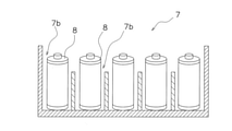
- FIG. 4 is a perspective view of the case.
- FIG. 5 is a cross-sectional view of the case and the secondary battery.
- the case 7 is a container having an opening 7a on the upper surface. Specifically, the case 7 has a plurality of spaces partitioned by partitions, and the secondary battery 8 is housed in each space.
- the term "case 7" includes a state in which the secondary battery 8 is housed.
- a predetermined interval and number of fire detectors 9 are provided on each shelf 6 of the rack or for each of the plurality of shelves 6.
- the fire detector 9 is connected to the system controller 53 (described later).
- the fire detector 9 is a known technique, and the type is not particularly limited.
- the automated warehouse 1 has a submersion tank 10.
- the submersion tank 10 is a water tank for submerging the case 7 in which a fire has occurred.
- the submersion tank 10 is provided on one side of the rack 2 in the X direction.
- the submersion tank 10 is provided with a lifter (not shown), and when the case 7 is handed over to the lifter, the lifter is lowered, whereby the case 7 is submerged in water.
- the stacker crane 3 will be described with reference to FIG.
- the stacker crane 3 is guided so as to be movable in the X direction along the rail 4.
- the stacker crane 3 is provided on the traveling bogie 12, a pair of masts 13 provided on both sides of the upper part of the traveling carriage 12 in the X direction, an elevating table 14 mounted on the mast 13 so as to be able to move up and down, and a case provided on the elevating table 14. It has a slide fork 15 for transferring the 7.
- the traveling carriage 12 is provided with wheels (not shown) having the upper surface of the rail 4 as the traveling surface.
- the traveling bogie 12 further has a traveling motor (not shown) and a speed reducer (not shown) for rotating the wheels (not shown).
- the elevating table 14 has a pair of guide members 25 guided by the mast 13 and a support table 26 extending between the guide members 25.
- the stacker crane 3 has an elevating mechanism 27 (FIG. 9) for elevating and elevating the elevating table 14.
- the elevating mechanism 27 has a belt (not shown) for driving the elevating table 14, an elevating pulley (not shown), and an elevating motor (not shown) for driving the elevating pulley.
- a slide fork 15 is provided on the support base 26 of the lift base 14.
- the slide fork 15 can advance horizontally on both sides in the Y direction.
- the slide fork 15 is connected to a transfer motor (not shown) via a speed reducer or a belt.
- the case 7 on the elevating table 14 can be transferred to the shelf 6, and the case 7 on the shelf 6 can be transferred to the elevating table 14.
- the case 7 is mounted on the upper surface of the slide fork 15 (an example of the article mounting surface) when it is on the elevating table 14.
- the stacker crane 3 has a fire extinguishing device 31 as shown in FIGS. 6 and 9.
- the fire extinguishing device 31 is a device for initially extinguishing a fire in the rack 2.
- the fire extinguishing device 31 is provided on the elevating table 14.
- the fire extinguishing device 31 has, for example, a carbon dioxide gas cylinder (not shown) filled with carbon dioxide gas as a fire extinguishing agent, a fire hose (not shown), and a fire extinguishing nozzle 33.
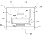
- FIG. 6 is a schematic front view of the elevating table (before the cover is separated).
- FIG. 7 is a schematic plan view of the elevator.
- FIG. 8 is a schematic front view of the locking device.
- the fire suppression device 41 is a device that suppresses the case 7 in which the initial fire is extinguished from reigniting in the elevating table 14.
- the fire suppression device 41 is provided on the elevating table 14.
- the fire suppression device 41 has a cover 43 and a lock device 45 that holds the cover 43 detachably.
- the cover 43 is arranged above the slide fork 15 in the elevating table 14. When the cover 43 is separated, it moves downward toward the slide fork 15.
- the cover 43 is larger than the case 7 and has a size capable of covering the case 7. More specifically, the cover 43 is close to the outer shape of the case 7, that is, has a rectangular box shape in a plan view including a flat surface portion 43a and a side surface portion 43b. Further, the cover 43 is made of a flame-retardant or non-flammable material.
- the cover 43 may be an iron plate, a non-combustible board, or a non-combustible sheet, or may be a structure made of another material to which the non-combustible board or the non-combustible sheet is attached.
- the lock device 45 normally holds the cover 43, and after the case 7 is transferred to the elevating table 14, the cover 43 is separated by releasing the holding.
- the cover 43 moves toward the slide fork 15 due to its own weight. That is, the operation of covering the case 7 by the cover 43 is executed only by releasing the holding of the lock device 45.
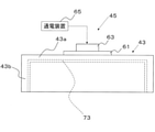
- FIG. 8 is a schematic front view of the fire suppression device.
- the lock device 45 has a magnetic body 61 mounted on the upper surface of the cover 43, an electromagnet 63 arranged above the magnetic body 61, and an energizing device 65.
- the electromagnet 63 holds the magnetic body 61 fixedly by magnetic force. Therefore, as shown in FIG. 6, the cover 43 is maintained at a position separated above the slide fork 15 and the case 7.
- FIG. 11 is a schematic front view (after the cover is separated) of the elevating table.
- the fire suppression device 41 further includes a guide 47 that supports the cover 43 so as to be movable in the vertical direction.
- the presence of the guide 47 can prevent the cover 43 from unnecessarily shaking during normal times, and the cover 43 can be dropped to a target position when it is separated.
- the guide 47 is a member that extends from above and supports the four corners of the cover 43 in the vertical direction.
- the guide 47 normally supports the upper portion of the cover 43 in FIG. Therefore, in normal times, the swing of the cover 43 is suppressed.
- the guide 47 is separated from the upper part of the cover 43 when the cover of FIG. 11 is dropped. Therefore, when the case 7 and the cover 43 move, the guide 47 does not interfere with those members.
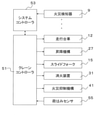
- FIG. 9 is a block diagram showing a control configuration of the stacker crane.
- the stacker crane 3 has a crane controller 51.
- the crane controller 51 can communicate with the system controller 53 that controls the entire automated warehouse 1.
- the crane controller 51 has a processor (for example, a CPU), a storage device (for example, ROM, RAM, HDD, SSD, etc.), and various interfaces (for example, an A / D converter, a D / A converter, a communication interface, etc.). It is a computer system.
- the crane controller 51 performs various control operations by executing a program stored in the storage unit (corresponding to a part or all of the storage area of the storage device).
- the crane controller 51 may be composed of a single processor, or may be composed of a plurality of independent processors for each control. A part or all of the functions of each element of the crane controller 51 may be realized as a program that can be executed by the computer system constituting the control unit. In addition, a part of the function of each element of the control unit may be configured by a custom IC.
- a traveling carriage 12, an elevating mechanism 27, and a slide fork 15 are connected to the crane controller 51, and the crane controller 51 can control these devices.
- a fire extinguishing device 31 and a fire suppression device 41 are connected to the crane controller 51, and the crane controller 51 can control these devices.
- Various sensors such as a load presence detection sensor (not shown) and a load load sensor 55 are further connected to the crane controller 51.
- the crane controller 51 is connected to a sensor that detects the size, shape, and position of the case 7, a sensor and a switch for detecting the state of each device, and an information input device.
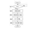
- FIG. 10 is a flowchart showing a fire extinguishing control operation.
- the control flowchart described below is an example, and each step can be omitted or replaced as necessary. Further, a plurality of steps may be executed at the same time, or some or all of them may be executed in an overlapping manner. Further, each block of the control flowchart is not limited to a single control operation, and can be replaced with a plurality of control operations represented by a plurality of blocks.
- the operation of each device is the result of a command from the control unit to each device, and these are represented by each step of the software application.
- step S1 it is determined whether or not a fire has occurred in the rack 2. Specifically, the system controller 93 executes the above determination based on the detection signal from the fire detector 9. At this time, it is also detected in which case 7 of the shelf 6 a fire has occurred.
- step S2 the stacker crane 3 performs an initial (primary) fire extinguishing activity in the shelf 6. Specifically, when the system controller 53 receives the fire detection signal from the fire detector 9, it notifies the crane controller 51 of the stacker crane 3 to that effect. Then, the stacker crane 3 moves the elevating table 14 in front of the shelf 6 and injects carbon dioxide gas from the fire extinguishing nozzle 33 toward the case 7 to extinguish the fire.
- step S3 the slide fork 15 of the stacker crane 3 transfers the case 7 to the inside of the elevating table 14.
- the case 7 is placed on the upper surface of the slide fork 15 (an example of the article mounting surface) as shown in FIG.
- various sensors for example, the load sensor 55 are set to be invalid.
- step S4 the cover 43 is separated and dropped. As a result, as shown in FIG. 11, the cover 43 covers the case 7. At this time, for example, since the load sensor 55 is on the outside of the cover 43, it is protected from the flame and the high temperature state in the case 7 thereafter.
- step S5 the stacker crane 3 conveys the case 7 to the submerged tank 10, and puts the case 7 into the submerged tank 10 together with the cover 43.
- the cover 43 suppresses the spread of the flame in the case 7. It should be noted that the disconnection of the cover 43 (step S4) and the start of the transport of the case 7 (step S5) may be opposite to each other.
- the cover 43 Since it is sufficient if the cover 43 can be separated, it has a simple structure and is highly reliable by reducing the number of driving parts. Since the cover 43 is separated from the lock device 45, for example, the cover 43 can be put together when the case 7 is put into the submersion tank 10, for example. That is, it is not necessary to return the cover 43 to the original position when the case 7 is put into the submerged tank 10.
- the cover is moved by its own weight after being separated, but the moving method is not particularly limited as long as the cover needs to be moved to the side on which the article is placed.
- the cover may be urged by, for example, other members.
- FIG. 12 is a schematic front view (before the cover is separated) of the elevating table of the second embodiment. Since the second embodiment has the same basic configuration and operation as the first embodiment, only the differences will be described.
- the elevating table 14 has an elastic member 71 that urges the cover 43 toward the upper surface of the slide fork 15.
- the elastic member 71 is a compression spring. Further, the elastic member 71 may be a coil spring, a leaf spring, or another spring. The elastic member 71 may be rubber or another elastic member. When the cover is separated, the elastic member 71 pushes the cover 43 downward so that the cover 43 can be moved quickly and surely.
- At least the inner surface of the cover is a nonflammable or flame-retardant material, but another material contributing to fire extinguishing may be applied to the inner surface.
- a nonflammable or flame-retardant material such an embodiment will be described as a third embodiment with reference to FIG.
- FIG. 13 is a schematic front view of the cover of the third embodiment.
- an effervescent fire extinguishing agent 73 that foams due to high temperature is provided on the inner surface of the cover 43.
- the foaming fire extinguishing agent 73 expands by foaming and fills the inside of the cover 43 to extinguish the fire.
- the foaming fire extinguishing agent is, for example, a chemical foaming agent, a physical foaming agent, or an effervescent microcapsule.
- the foam fire extinguishing agent 73 may be provided only on one of the flat surface portion 43a and the side surface portion 43b of the cover.
- the stacker crane (for example, the stacker crane 3) takes out an article (for example, a case 7) from a plurality of shelves (for example, a shelf 6) and conveys the article (for example, a case 7), and transfers a traveling device, a mast, an elevating table, and the like. It is equipped with a mounting device and a cover.
- the mast (for example, the mast 13) is provided on the traveling device (for example, the traveling carriage 12).
- the lift (eg, lift 14) moves up and down along the mast.
- the transfer device (for example, the slide fork 15) transfers the article on the lift.
- the cover (eg, cover 43) is made of a flame-retardant or non-flammable material and is detachably supported so as to move towards the article mounting surface of the lift (eg, the upper surface of the slide fork 15). ..
- the stacker crane transfer device places the article on the article mounting surface of the lift. Subsequently, the cover is separated and moved so that the cover covers the article. After that, the stacker crane, for example, conveys the article to the submerged tank (for example, the submerged tank 10), and puts the article together with the cover into the submerged tank.
- the submerged tank for example, the submerged tank 10
- the lock device is not limited in specific structure as long as the cover can be separated.
- the locking device may be a mechanism in which a flange is provided on the upper surface of the cover and the lower portion thereof is supported by a movable member. The cover can be dropped by moving the movable member laterally or diagonally downward.
- the locking device may also be a mechanism in which a member with a hole is provided on the upper surface of the cover and the member is held through the pin. By pulling out the pin, the pin and the member with a hole can be disengaged and the cover can be dropped.
- the locking device may be a mechanism in which a ring is provided on the upper surface of the cover and a hook is hooked on the ring to hold the ring. By rotating the hook, the ring and the hook can be disengaged and the cover can be dropped.
- the shape of the cover is not particularly limited as long as it can suppress the spread of the flame. Since the cover may be transferred together with the article, it does not have to come into contact with the article mounting surface of the elevator when dropped. That is, the cover may only contact the top of the case.
- the size of the cover can be kept to a minimum as long as the cover has at least a shape that can close the opening of the container.
- the cover should cover at least a part of the opening of the case, thereby preventing the flame from spreading to the outside.
- the cover covers the upper part and the side part of the case, but it may cover only the upper part or only a part of the upper part and the side part.
- the cover may seal the opening of the container or may be located away from the opening.
- the cover is not limited to the box shape. For example, the cover may be flat.
- the article transfer device provided on the support base of the lift is not limited to the slide fork.
- the transfer device may be a rear or front hook type.
- the case may be transferred between the elevating table and the shelf by providing hooks on the arms that can advance horizontally on both sides in the Y direction and hooking the hooks on the case. At this time, if the cover has a shape that covers only the upper part of the case, it does not interfere with the arm.
- the article placing surface is a place on the elevating table where the article is placed by the transfer device.
- the article mounting surface is not limited to the upper surface of the slide fork, as long as the article can be moved together with the lift. For example, it may be a bottom surface provided on a lift.
- the guide may support all four sides.
- the guide may have a rotating member such as a roller.
- the guide may be omitted.
- the shelf for accommodating the secondary battery may be a part of the battery charging / discharging equipment.
- An electric device for charging and discharging a secondary battery is used as a processing device, a battery container containing a plurality of secondary batteries is used as an article, and this battery container is delivered and received to the electric device by an article transport device. It is described that it is configured in.
- each process such as charging, aging, and discharging of the plurality of secondary batteries 8 housed in the case 7 is performed.
- the shelf itself may be provided with a fire extinguishing device such as a sprinkler.
- the fire extinguishing device of the stacker crane may be omitted.
- the fire extinguishing device may be provided on the mast of the stacker crane.
- the fire extinguishing agent may be a highly foaming foam-like fire extinguishing agent or a powder-like fire extinguishing agent.
- the article may not be transported to the submerged tank.
- the configuration of the submersion tank is not particularly limited. Instead of the submersion tank, it may be transported to another fire extinguishing facility.
- Another fire extinguishing device is, for example, a fire extinguishing system that injects a fire extinguishing agent such as water onto an article.
- the configuration and shape of the battery storage case are not particularly limited.
- the article may be something other than a secondary battery or a case.
- the present invention can be widely applied to a stacker crane having a fire suppression function.
Abstract
Description
自動倉庫は、ラックの棚に荷物を下ろす又はラックの棚から荷物を積み込むための搬送装置として、スタッカクレーンを有している。スタッカクレーンは、レールに沿って走行する走行装置と、移載装置と、移載装置を上下方向に移動させる昇降装置とを有している。レールの一部はラックの側方に並んで配置されており、スタッカクレーンは、ラックの側方において目的の棚の近傍に移載装置を配置して、その状態で荷物を移載する。 Traditional automated warehouses have multiple racks. Each rack is arranged side by side in parallel and has a plurality of shelves arranged in the stretching direction and the vertical direction.
The automated warehouse has a stacker crane as a transport device for unloading cargo on rack shelves or loading cargo from rack shelves. The stacker crane has a traveling device that travels along the rail, a transfer device, and an elevating device that moves the transfer device in the vertical direction. A part of the rail is arranged side by side on the side of the rack, and the stacker crane arranges the transfer device near the target shelf on the side of the rack and transfers the load in that state.
例えば、スタッカクレーンは、消火装置、延焼防止装置を有している。消火装置は、例えば、ラックに収納されている二次電池の初期消火を行う。延焼防止装置は、シャッタからなり、昇降台に載せられた二次電池を覆うことで、荷物搬送中に電池セルの飛散防止、延焼防止を実現する。最後に、スタッカクレーンは、シャッタで覆われた荷物を水没槽まで搬送して、荷物を水没槽に投入する。 Conventionally, the stacker crane installed in the secondary battery manufacturing process is equipped with various fire protection functions as a fire countermeasure for the battery cell of the secondary battery.
For example, a stacker crane has a fire extinguishing device and a fire spread prevention device. The fire extinguishing device, for example, performs initial fire extinguishing of a secondary battery housed in a rack. The fire spread prevention device consists of a shutter and covers the secondary battery mounted on the elevating table to prevent the battery cells from scattering and prevent the spread of fire during the transportation of luggage. Finally, the stacker crane transports the cargo covered with the shutter to the submerged tank and puts the load into the submerged tank.
また、シャッタ内で火勢が強まった場合、センサ類への影響やシャッタの動作不具合が生じる可能性がある。シャッタを開けなくなれば、荷物を水没槽に投入できなくなる。 In the above-mentioned conventional technique, the shutter has a complicated structure and the number of parts increases, so that the structural space and cost increase.
In addition, if the fire force in the shutter becomes stronger, there is a possibility that the sensors may be affected or the shutter may malfunction. If the shutter cannot be opened, the luggage cannot be put into the submerged tank.
マストは走行装置に設けられている。
昇降台は、マストに沿って昇降する。
移載装置は、昇降台上に物品を移載する。
カバーは、難燃性又は不燃性の材料からなり、昇降台の物品載置面に向かって移動するように切り離し可能に支持されている。 The stacker crane according to a seemingly present invention is for taking out articles from a plurality of shelves and transporting them, and includes a traveling device, a mast, an elevating table, a transfer device, and a cover.
The mast is provided on the traveling device.
The platform moves up and down along the mast.
The transfer device transfers the article on the lift.
The cover is made of a flame-retardant or non-flammable material and is detachably supported so as to move towards the article mounting surface of the lift.
なお、カバー切り離しと物品の搬送開始とは、先後反対でもよい。
なお、カバーによって物品を覆う作業の後に物品とカバーを搬送する先は、他の消火施設であってもよい。 In this stacker crane, when a fire breaks out on an article on a shelf, for example, after the initial fire extinguishing, the stacker crane transfer device places the article on the article mounting surface of the lift. Subsequently, the cover is separated and moved so that the cover covers the article. After that, the stacker crane, for example, transports the article to the submerged tank and puts the article together with the cover into the submerged tank.
It should be noted that the removal of the cover and the start of transportation of the article may be opposite to each other.
The destination for transporting the article and the cover after the work of covering the article with the cover may be another fire extinguishing facility.
特に、カバーは難燃性又は不燃性の材料からなるので、昇降台上で物品から再出火した場合でも、延焼を防止できる。 By providing the cover as described above, it is possible to prevent the flame from scattering or spreading when the initially extinguished article is transported to, for example, a submerged tank. In addition, the sensor on the elevator is also protected by the cover.
In particular, since the cover is made of a flame-retardant or non-flammable material, it is possible to prevent the spread of fire even if the article reignites on the elevator.
特に、カバーは例えば保持部から切り離されているので、物品を例えば水没槽へ投入する際にカバーも一緒に投入できる。つまり、物品を水没槽に投入する際にカバーを元の位置に戻す等の操作が不要である。 In particular, since it is sufficient if the cover can be separated, it has a simple structure and is highly reliable by reducing the number of drive parts.
In particular, since the cover is separated from the holding portion, for example, the cover can be put together when the article is put into the submersion tank, for example. That is, it is not necessary to return the cover to the original position when the article is put into the submerged tank.
このスタッカクレーンでは、カバーは物品を覆うことができるので、確実に延焼や火炎の飛散を防止できる。 The cover may be larger than the article and have a size capable of covering the article. The cover is, for example, a box-shaped lid that is close to the outer shape of the article.
In this stacker crane, the cover can cover the article, so that it is possible to surely prevent the spread of fire and the scattering of flames.
このスタッカクレーンでは、物品の上面の開口部を覆うことで、カバーのサイズを最小限にとどめることができる。 The article may be a container having an opening on the upper surface. The cover may be at least in a shape capable of closing the opening of the container. In addition, "close" is a state in which a part or all of the opening is covered from above.
In this stacker crane, the size of the cover can be kept to a minimum by covering the opening on the upper surface of the article.
カバーを通常時に保持しており、カバーを切り離し可能なロック装置と、
物品火災発生後に物品が物品載置面に置かれたことを検出するセンサと、
センサからの検出情報に応じてカバーを切り離させるコントローラと、
をさらに備えていてもよい。
このスタッカクレーンでは、カバー切り離し動作は、ロック装置の保持を解除するだけで実行される。 Stacker crane
A locking device that holds the cover normally and allows the cover to be detached,
A sensor that detects that an article has been placed on the article placement surface after an article fire has occurred,
A controller that detaches the cover according to the detection information from the sensor,
May be further provided.
In this stacker crane, the cover disconnection operation is performed only by releasing the holding of the locking device.
このスタッカクレーンでは、カバーを駆動する駆動部品を減らすことができ、そのため信頼性が向上する。 The cover may be movable toward the article mounting surface by its own weight.
This stacker crane can reduce the number of drive components that drive the cover, thus improving reliability.
このスタッカクレーンでは、弾性部材によって、カバーを押し出すことで素早く、確実に移動させることができる。 The stacker crane may further include an elastic member that urges the cover towards the article mounting surface.
In this stacker crane, the elastic member pushes out the cover so that it can be moved quickly and reliably.
このスタッカクレーンでは、ガイドがあることにより通常時にカバーが不必要に揺れることを防止でき、切り離し時はカバーを物品載置面上の狙った位置に落下させることができる。 The stacker crane may further be equipped with a guide that supports the cover in a vertically movable manner.
In this stacker crane, the presence of the guide can prevent the cover from unnecessarily shaking during normal times, and the cover can be dropped to the target position on the article mounting surface at the time of disconnection.
このスタッカクレーンでは、カバーが物品を覆ってから高温状態が維持又は再開されたなら、発泡消火剤が発泡してカバー内を充填することで、消火を行う。
なお、発泡消火剤とは、例えば、化学発泡剤、物理発泡剤、発泡性マイクロカプセルである。 The stacker crane may further include an effervescent fire extinguishing agent provided on the inner surface of the cover and foamed by high temperature.
In this stacker crane, when the high temperature state is maintained or restarted after the cover covers the article, the foaming fire extinguishing agent foams to fill the inside of the cover to extinguish the fire.
The foaming fire extinguishing agent is, for example, a chemical foaming agent, a physical foaming agent, or an effervescent microcapsule.
(1)自動倉庫全体
図1及び図2を用いて、本発明に係る一実施形態としての自動倉庫1を説明する。図1は、第1実施形態が採用された自動倉庫の概略平面図である。図2は、自動倉庫の概略側面図である。
なお、以下の説明で用いる「X方向」はスタッカクレーン3の走行方向であり、「Y方向」は移載装置による物品の移載方向であり、「Z方向」は移載装置の昇降方向である。X方向、Y方向及びZ方向は互いに直交している。 1. 1. 1st Embodiment (1) Overall Automatic Warehouse With reference to FIGS. 1 and 2, an
In the following description, the "X direction" is the traveling direction of the
ラック2は、第1ラック2A及び第2ラック2Bを有している。第1ラック2A及び第2ラック2Bは、図1のX方向に延びるスタッカクレーン通路にあるレール4を挟むようにY方向に並んで配置されている。第1ラック2A及び第2ラック2Bは、X方向とZ方向に並んだ複数の棚6から構成されている。 (2) Rack The
ケース7は、上面に開口部7aを有する容器である。具体的には、ケース7は、仕切りによって区画された複数のスペースを有しており、各スペースには二次電池8が収納される。なお、以下の説明では、単に「ケース7」と記載する場合は、二次電池8を収納した状態を含む。
The
水没槽10にはリフタ(図示せず)が設けられており、ケース7がリフタに受け渡されると、リフタが下降し、これによりケース7が水中に沈められる。 As shown in FIG. 1, the
The
図2を用いて、スタッカクレーン3を説明する。
スタッカクレーン3は、レール4に沿って、X方向に移動可能に案内されている。スタッカクレーン3は、走行台車12と、走行台車12の上部のX方向両側に設けられた一対のマスト13と、マスト13に昇降自在に装着された昇降台14と、昇降台14に設けられケース7を移載するためのスライドフォーク15とを有している。 (3) Mechanism of Stacker Crane The
The
スライドフォーク15は、昇降台14にあるケース7を棚6に移載したり、棚6にあるケース7を昇降台14に移載したりできる。ケース7は、図6に示すように、昇降台14にあるときにはスライドフォーク15の上面(物品載置面の一例)に載っている。 A
In the
消火装置31は、例えば、消火剤として炭酸ガスが充填された炭酸ガスボンベ(図示せず)と、消火ホース(図示せず)と、消火ノズル33とを有している。そして、棚6に収納されているケース7に発煙や火災が発生した場合には、火災検知器9により火災が検出され、その検出情報に基づいて、消火装置31による消火処理が行われる。 The
The
スタッカクレーンは、火災抑制装置41を有している。
図6~図8を用いて、火災抑制装置41を説明する。図6は、昇降台の模式的正面図(カバー切り離し前)である。図7は、昇降台の模式的平面図である。図8は、ロック装置の模式的正面図である。
火災抑制装置41は、初期消火が行われたケース7が昇降台14内で再出火するのを抑える装置である。火災抑制装置41は、昇降台14に設けられている。
火災抑制装置41は、カバー43と、カバー43を切り離し可能に保持するロック装置45とを有している。カバー43は、昇降台14内においてスライドフォーク15の上方に配置されている。カバー43は、切り離されると、スライドフォーク15に向かって下方に移動する。 (4) Fire suppression device The stacker crane has a
The
The
The
また、カバー43は、難燃性又は不燃性の材料からなる。例えば、カバー43は、鉄板、不燃ボード、不燃シートのいずれかであってもよく、他の材料からなる構造に不燃ボード又は不燃シートが貼られたものでもよい。 Specifically, the
Further, the
カバー43は、自重によりスライドフォーク15へ向かって移動する。つまり、カバー43によるケース7を覆う動作は、ロック装置45の保持を解除するだけで実行される。 The
The
ロック装置45は、図8に示すように、カバー43の上面に装着された磁性体61と、その上方に配置された電磁石63と、通電装置65とを有している。通電装置65から電磁石63への通電がONされていると、電磁石63が磁性体61を磁力により固定保持している。したがって、カバー43は、図6に示すように、スライドフォーク15及びケース7の上方に離れた位置に維持されている。
電磁石63への通電がOFFされると、電磁石63の磁力が消滅して、磁性体61が電磁石63から離れる。それにより、カバー43は落下する。カバー43は鉛直方向への落下を続けた後に、最終的に、図11に示すように、スライドフォーク15に衝突する。つまり、カバー43の側面部43bの下面が、スライドフォーク15の上に載った状態になる。このとき、カバー43の平面部43aの下面がケース7の上面に当接していても、離れていてもよい。なお、図11は、昇降台の模式的正面図(カバー切り離し後)である。 The detailed configuration of the
As shown in FIG. 8, the
When the energization of the
具体的には、ガイド47は、上方から延びて、カバー43の四隅を鉛直方向に支持する部材である。ガイド47は、図6の通常時にはカバー43の上側部分を支持している。したがって、通常時にはカバー43の揺動が抑えられている。ガイド47は、図11のカバー落下時にはカバー43の上部から離れている。したがって、ケース7及びカバー43が移動する際に、ガイド47がそれら部材に干渉することがない。 The
Specifically, the
図9を用いて、スタッカクレーン3の制御構成を説明する。図9は、スタッカクレーンの制御構成を示すブロック図である。
スタッカクレーン3は、クレーンコントローラ51を有している。クレーンコントローラ51は、自動倉庫1全体を制御するシステムコントローラ53と通信可能である。
クレーンコントローラ51は、プロセッサ(例えば、CPU)と、記憶装置(例えば、ROM、RAM、HDD、SSDなど)と、各種インターフェース(例えば、A/Dコンバータ、D/Aコンバータ、通信インターフェースなど)を有するコンピュータシステムである。クレーンコントローラ51は、記憶部(記憶装置の記憶領域の一部又は全部に対応)に保存されたプログラムを実行することで、各種制御動作を行う。 (5) Control Configuration of Stacker Crane The control configuration of the
The
The
クレーンコントローラ51の各要素の機能は、一部又は全てが、制御部を構成するコンピュータシステムにて実行可能なプログラムとして実現されてもよい。その他、制御部の各要素の機能の一部は、カスタムICにより構成されていてもよい。 The
A part or all of the functions of each element of the
クレーンコントローラ51には、消火装置31及び火災抑制装置41が接続されており、クレーンコントローラ51はこれら装置を制御可能である。
クレーンコントローラ51には、さらに、荷存在検出センサ(図示せず)、荷はみセンサ55といった各種センサが接続されている。
クレーンコントローラ51には、図示しないが、ケース7の大きさ、形状及び位置を検出するセンサ、各装置の状態を検出するためのセンサ及びスイッチ、並びに情報入力装置が接続されている。 A traveling
A
Various sensors such as a load presence detection sensor (not shown) and a
Although not shown, the
図10を用いて、スタッカクレーン3がケース7を消火する動作を説明する。図10は、消火制御動作を示すフローチャートである。
以下に説明する制御フローチャートは例示であって、各ステップは必要に応じて省略及び入れ替え可能である。また、複数のステップが同時に実行されたり、一部又は全てが重なって実行されたりしてもよい。
さらに、制御フローチャートの各ブロックは、単一の制御動作とは限らず、複数のブロックで表現される複数の制御動作に置き換えることができる。
なお、各装置の動作は、制御部から各装置への指令の結果であり、これらはソフトウェア・アプリケーションの各ステップによって表現される。 (6) Fire extinguishing operation The operation of the
The control flowchart described below is an example, and each step can be omitted or replaced as necessary. Further, a plurality of steps may be executed at the same time, or some or all of them may be executed in an overlapping manner.
Further, each block of the control flowchart is not limited to a single control operation, and can be replaced with a plurality of control operations represented by a plurality of blocks.
The operation of each device is the result of a command from the control unit to each device, and these are represented by each step of the software application.
ステップS2では、スタッカクレーン3により棚6内での初期(一次)消火活動が行われる。具体的には、システムコントローラ53は火災検知器9による火災感知の信号を受信すると、スタッカクレーン3のクレーンコントローラ51にその旨を通知する。そして、スタッカクレーン3は、昇降台14を当該棚6の前に移動し、消火ノズル33から炭酸ガスをケース7に向けて噴射して消火を行う。 In step S1, it is determined whether or not a fire has occurred in the
In step S2, the
なお、カバー43の切り離し(ステップS4)とケース7の搬送(ステップS5)の開始とは、先後反対でもよい。 In step S5, the
It should be noted that the disconnection of the cover 43 (step S4) and the start of the transport of the case 7 (step S5) may be opposite to each other.
上記のようにカバー43が設けられていることで、初期消火したケース7を例えば水没槽10へ搬送する際に、ケース7の飛散や延焼を防止できる。また、昇降台14上の荷はみセンサ55(昇降台14に設けられた各種センサの一例)などもカバー43によって保護される。
カバー43は難燃性又は不燃性の材料からなるので、昇降台14上でケース7から再出火した場合でも、延焼を防止できる。 (7) Effect of Embodiment By providing the
Since the
カバー43は例えばロック装置45から切り離されているので、ケース7を例えば水没槽10へ投入する際にカバー43も一緒に投入できる。つまり、ケース7を水没槽10に投入する際にカバー43を元の位置に戻す等の操作が不要である。 Since it is sufficient if the
Since the
第1実施形態ではカバーは切り離された後に自重によって移動したが、カバーは物品載置面側に移動しさえすればよいので、移動方法は特に限定されない。カバーは例えば他の部材によって付勢力を与えられてもよい。
図12を用いて、そのような実施例を第2実施形態として説明する。図12は、第2実施形態の昇降台の模式的正面図(カバー切り離し前)である。なお、第2実施形態は基本的な構成及び動作が第1実施形態と同じであるので、異なる点のみを説明する。 2. 2. 2nd Embodiment In the 1st embodiment, the cover is moved by its own weight after being separated, but the moving method is not particularly limited as long as the cover needs to be moved to the side on which the article is placed. The cover may be urged by, for example, other members.
Such an embodiment will be described as a second embodiment with reference to FIG. FIG. 12 is a schematic front view (before the cover is separated) of the elevating table of the second embodiment. Since the second embodiment has the same basic configuration and operation as the first embodiment, only the differences will be described.
カバー切り離し時には、弾性部材71によって、カバー43を下方に押し出すことで素早く、確実に移動させることができる。 As shown in FIG. 12, the elevating table 14 has an
When the cover is separated, the
第1実施形態ではカバーの少なくとも内側面は不燃性又は難燃性材料であったが、消火に貢献する他の材料が内側面に塗布されていてもよい。
図13を用いて、そのような実施例を第3実施形態として説明する。図13は、第3実施形態のカバーの模式的正面図である。 3. 3. Third Embodiment In the first embodiment, at least the inner surface of the cover is a nonflammable or flame-retardant material, but another material contributing to fire extinguishing may be applied to the inner surface.
Such an embodiment will be described as a third embodiment with reference to FIG. FIG. 13 is a schematic front view of the cover of the third embodiment.
この実施形態では、カバー43がケース7を覆ってから高温状態が維持又は再開されたなら、発泡消火剤73が発泡膨張してカバー43内を充填することで、消火を行う。
なお、発泡消火剤とは、例えば、化学発泡剤、物理発泡剤、発泡性マイクロカプセルである。
発泡消火剤73は、カバーの平面部43a及び側面部43bの一方のみに設けられていてもよい。 As shown in FIG. 13, an effervescent
In this embodiment, when the high temperature state is maintained or restarted after the
The foaming fire extinguishing agent is, for example, a chemical foaming agent, a physical foaming agent, or an effervescent microcapsule.
The foam
上記第1~第3実施形態は、下記の構成及び機能を共通に有している。
スタッカクレーン(例えば、スタッカクレーン3)は、複数の棚(例えば、棚6)から物品(例えば、ケース7)を取り出して搬送するものであって、走行装置と、マストと、昇降台と、移載装置と、カバーとを備えている。
マスト(例えば、マスト13)は走行装置(例えば、走行台車12)に設けられている。
昇降台(例えば、昇降台14)は、マストに沿って昇降する。
移載装置(例えば、スライドフォーク15)は、昇降台上に物品を移載する。
カバー(例えば、カバー43)は、難燃性又は不燃性の材料からなり、昇降台の物品載置面(例えば、スライドフォーク15の上面)に向かって移動するように切り離し可能に支持されている。 4. Common items of the embodiments The first to third embodiments have the following configurations and functions in common.
The stacker crane (for example, the stacker crane 3) takes out an article (for example, a case 7) from a plurality of shelves (for example, a shelf 6) and conveys the article (for example, a case 7), and transfers a traveling device, a mast, an elevating table, and the like. It is equipped with a mounting device and a cover.
The mast (for example, the mast 13) is provided on the traveling device (for example, the traveling carriage 12).
The lift (eg, lift 14) moves up and down along the mast.
The transfer device (for example, the slide fork 15) transfers the article on the lift.
The cover (eg, cover 43) is made of a flame-retardant or non-flammable material and is detachably supported so as to move towards the article mounting surface of the lift (eg, the upper surface of the slide fork 15). ..
以上、本発明の一実施形態について説明したが、本発明は上記実施形態に限定されるものではなく、発明の要旨を逸脱しない範囲で種々の変更が可能である。特に、本明細書に書かれた複数の実施形態及び変形例は必要に応じて任意に組み合せ可能である。 5. Other Embodiments Although one embodiment of the present invention has been described above, the present invention is not limited to the above embodiment, and various modifications can be made without departing from the gist of the invention. In particular, the plurality of embodiments and modifications described herein can be arbitrarily combined as needed.
ロック装置は、カバーを切り離すことができればよいので、具体的な構造は限定されない。
ロック装置は、カバーの上面にフランジを設けて、その下部を移動可能部材によって支持する機構でもよい。移動可能部材を側方又は斜め下方に移動させることで、カバーを落下させることができる。
ロック装置は、カバーの上面に穴付き部材をも設けそれにピンを通して保持する機構でもよい。ピンを抜くことでピンと穴付き部材の係合を解除して、カバーを落下させることができる。
ロック装置は、カバーの上面にリングを設け、それにフックを引っ掛けて保持する機構でもよい。フックを回転することでリングとフックの係合を解除して、カバーを落下させることができる。 (1) Modification example of lock device The lock device is not limited in specific structure as long as the cover can be separated.
The locking device may be a mechanism in which a flange is provided on the upper surface of the cover and the lower portion thereof is supported by a movable member. The cover can be dropped by moving the movable member laterally or diagonally downward.
The locking device may also be a mechanism in which a member with a hole is provided on the upper surface of the cover and the member is held through the pin. By pulling out the pin, the pin and the member with a hole can be disengaged and the cover can be dropped.
The locking device may be a mechanism in which a ring is provided on the upper surface of the cover and a hook is hooked on the ring to hold the ring. By rotating the hook, the ring and the hook can be disengaged and the cover can be dropped.
カバーは火炎の広がりを抑えることができればよいので、形状は特に限定されない。
カバーは物品と共に移載可能であればよいので、落下時に昇降台の物品載置面には当接しなくてもよい。つまり、カバーはケースの上のみに当接してもよい。
カバーは少なくとも容器の開口部を塞ぐことができる形状であればよいので、カバーのサイズを最小限にとどめることができる。カバーはケースの開口部の少なくとも一部を覆っており、それにより火炎が外部に広がりにくくなっていればよい。第1実施形態ではカバーはケース上部及び側部を覆っているが、上部のみを覆っていてもよいし、上部及び側部の一部のみを覆っていてもよい。
カバーは容器の開口部を密封していてもよいし、開口部から離れて配置されていてもよい。
カバーは箱形状に限定されない。例えば、カバーは、平板状であってもよい。 (2) Deformation example of the cover The shape of the cover is not particularly limited as long as it can suppress the spread of the flame.
Since the cover may be transferred together with the article, it does not have to come into contact with the article mounting surface of the elevator when dropped. That is, the cover may only contact the top of the case.
The size of the cover can be kept to a minimum as long as the cover has at least a shape that can close the opening of the container. The cover should cover at least a part of the opening of the case, thereby preventing the flame from spreading to the outside. In the first embodiment, the cover covers the upper part and the side part of the case, but it may cover only the upper part or only a part of the upper part and the side part.
The cover may seal the opening of the container or may be located away from the opening.
The cover is not limited to the box shape. For example, the cover may be flat.
昇降台の支持台に設けられる物品移載装置は、スライドフォークに限定されない。
移載装置は、リア又はフロントのフック式でもよい。具体的には、Y方向両側でかつ水平方向に進出可能なアームにフックを設け、ケースにフックを引掛けることにより、昇降台と棚の間でケースを移載してもよい。このとき、カバーはケースの上部のみを覆う形状であれば、アームと干渉しない。 (3) Modification example of transfer device The article transfer device provided on the support base of the lift is not limited to the slide fork.
The transfer device may be a rear or front hook type. Specifically, the case may be transferred between the elevating table and the shelf by providing hooks on the arms that can advance horizontally on both sides in the Y direction and hooking the hooks on the case. At this time, if the cover has a shape that covers only the upper part of the case, it does not interfere with the arm.
物品載置面は、昇降台において、移載装置によって物品が置かれる場所である。物品載置面は、物品が昇降台と共に移動可能になればそれでよいので、スライドフォークの上面に限定されない。例えば、昇降台に設けられた底面であってもよい。 (4) Deformation example of the article placing surface The article placing surface is a place on the elevating table where the article is placed by the transfer device. The article mounting surface is not limited to the upper surface of the slide fork, as long as the article can be moved together with the lift. For example, it may be a bottom surface provided on a lift.
ガイドは四辺を支持してもよい。
ガイドは、コロ等の回転部材を有していてもよい。
ガイドは省略されてもよい。 (5) Modification example of the guide The guide may support all four sides.
The guide may have a rotating member such as a roller.
The guide may be omitted.
二次電池を収納する棚は、電池充放電設備の一部であってもよい。二次電池の充電及び放電を行う電気装置を処理装置とし、複数の二次電池を収容した電池容器を物品として、この電池容器を電気装置に対して物品搬送装置にて受け渡し及び受け取りを行うように構成することが記載されている。充放電設備では、ケース7に収容された複数の二次電池8に対する充電、エイジング、放電などの各工程が行われる。
棚自体に、例えばスプリンクラーのような消火装置が設けられていてもよい。 (6) Deformation example of the shelf The shelf for accommodating the secondary battery may be a part of the battery charging / discharging equipment. An electric device for charging and discharging a secondary battery is used as a processing device, a battery container containing a plurality of secondary batteries is used as an article, and this battery container is delivered and received to the electric device by an article transport device. It is described that it is configured in. In the charging / discharging equipment, each process such as charging, aging, and discharging of the plurality of
The shelf itself may be provided with a fire extinguishing device such as a sprinkler.
スタッカクレーンの消火装置は省略されてもよい。
消火装置は、スタッカクレーンのマストに設けられていてもよい。
消火剤としては、高発泡の泡状の消火剤、粉末状の消火剤であってもよい。 (7) Modification example of fire extinguishing device The fire extinguishing device of the stacker crane may be omitted.
The fire extinguishing device may be provided on the mast of the stacker crane.
The fire extinguishing agent may be a highly foaming foam-like fire extinguishing agent or a powder-like fire extinguishing agent.
消火装置及びカバーによる消火によって火災を鎮火できれば、物品を水没槽まで搬送しないようにしてもよい。
水没槽の構成は特に限定されない。
水没槽の代わりに、他の消火施設に搬送してもよい。他の消火装置は、例えば、水等の消火剤を物品に噴射する消火設備である。 (8) Deformation example of submerged tank If the fire can be extinguished by extinguishing the fire with a fire extinguishing device and a cover, the article may not be transported to the submerged tank.
The configuration of the submersion tank is not particularly limited.
Instead of the submersion tank, it may be transported to another fire extinguishing facility. Another fire extinguishing device is, for example, a fire extinguishing system that injects a fire extinguishing agent such as water onto an article.
電池収納ケースの構成や形状は特に限定されない。
物品は二次電池やケース以外のものであってもよい。 (9) Deformation example of the article The configuration and shape of the battery storage case are not particularly limited.
The article may be something other than a secondary battery or a case.
第1実施形態では一連の消火動作は自動で行われていたが、これら動作は自動ではなくてもよい。すなわち、火災検出、初期消火、カバーの切り離し、二次消火のいずれか又は全てを作業員の動作に基づいて行ってもよい。 (10) Modification example of fire extinguishing work In the first embodiment, a series of fire extinguishing operations are automatically performed, but these operations may not be automatic. That is, any or all of fire detection, initial fire extinguishing, cover disconnection, and secondary fire extinguishing may be performed based on the operation of the worker.
2 :ラック
2A :第1ラック
2B :第2ラック
3 :スタッカクレーン
4 :レール
6 :棚
6a :荷物支承部材
6b :フォーク通過間隙
7 :ケース
7a :開口部
8 :二次電池
9 :火災検知器
10 :水没槽
12 :走行台車
13 :マスト
14 :昇降台
15 :スライドフォーク
25 :ガイド部材
26 :支持台
27 :昇降機構
30 :物品
31 :消火装置
33 :消火ノズル
41 :火災抑制装置
43 :カバー
43a :平面部
43b :側面部
45 :ロック装置
47 :ガイド
51 :クレーンコントローラ
53 :システムコントローラ
55 :荷はみセンサ
61 :磁性体
63 :電磁石 1: Automated warehouse 2:
Claims (13)
- 複数の棚から物品を取り出して搬送するスタッカクレーンであって、
走行装置と、
前記走行装置に設けられたマストと、
前記マストに沿って昇降する昇降台と、
前記昇降台上に前記物品を移載する移載装置と、
難燃性又は不燃性の材料からなり、前記昇降台の物品載置面に向かって移動するように切り離し可能に支持されているカバーと、
を備えたスタッカクレーン。 A stacker crane that takes out articles from multiple shelves and transports them.
With the traveling device,
The mast provided on the traveling device and
An elevating platform that goes up and down along the mast,
A transfer device for transferring the article onto the elevator, and a transfer device.
A cover made of a flame-retardant or non-flammable material and supported detachably so as to move toward the article mounting surface of the lift.
Stacker crane equipped with. - 前記カバーは、前記物品より大きく、前記物品を覆うことができるサイズを有する、請求項1に記載のスタッカクレーン。 The stacker crane according to claim 1, wherein the cover is larger than the article and has a size capable of covering the article.
- 前記物品は、上面に開口部を有する容器であり、
前記カバーは少なくとも前記容器の前記開口部を塞ぐことができる形状である、請求項1に記載のスタッカクレーン。 The article is a container having an opening on the upper surface.
The stacker crane according to claim 1, wherein the cover has a shape capable of closing at least the opening of the container. - 前記カバーを通常時に保持しており、前記カバーを切り離し可能なロック装置と、
物品火災発生後に物品が前記物品載置面に置かれたことを検出するセンサと、
前記センサからの情報に応じて前記ロック装置に前記カバーを切り離させるコントローラと、をさらに備えている、請求項1に記載のスタッカクレーン。 A locking device that normally holds the cover and allows the cover to be detached,
A sensor that detects that an article has been placed on the article placement surface after an article fire has occurred, and
The stacker crane according to claim 1, further comprising a controller for causing the locking device to detach the cover in response to information from the sensor. - 前記カバーは、自重により前記物品載置面へ向かって移動可能である、請求項4に記載のスタッカクレーン。 The stacker crane according to claim 4, wherein the cover can be moved toward the article mounting surface by its own weight.
- 前記カバーを前記物品載置面へ向かって付勢する弾性部材をさらに備えている、請求項4に記載のスタッカクレーン。 The stacker crane according to claim 4, further comprising an elastic member for urging the cover toward the article mounting surface.
- 前記カバーを通常時に保持しており、前記カバーを切り離し可能なロック装置と、
物品火災発生後に物品が前記物品載置面に置かれたことを検出するセンサと、
前記センサからの情報に応じて前記ロック装置に前記カバーを切り離させるコントローラと、をさらに備えている、請求項2に記載のスタッカクレーン。 A locking device that normally holds the cover and allows the cover to be detached,
A sensor that detects that an article has been placed on the article placement surface after an article fire has occurred, and
The stacker crane according to claim 2, further comprising a controller for causing the locking device to detach the cover in response to information from the sensor. - 前記カバーは、自重により前記物品載置面へ向かって移動可能である、請求項7に記載のスタッカクレーン。 The stacker crane according to claim 7, wherein the cover can be moved toward the article mounting surface by its own weight.
- 前記カバーを前記物品載置面へ向かって付勢する弾性部材をさらに備えている、請求項7に記載のスタッカクレーン。 The stacker crane according to claim 7, further comprising an elastic member for urging the cover toward the article mounting surface.
- 前記カバーを上下方向に移動可能に支持するガイドをさらに備えている、請求項1に記載のスタッカクレーン。 The stacker crane according to claim 1, further comprising a guide that supports the cover so as to be movable in the vertical direction.
- 前記カバーを上下方向に移動可能に支持するガイドをさらに備えている、請求項2に記載のスタッカクレーン。 The stacker crane according to claim 2, further comprising a guide that supports the cover so as to be movable in the vertical direction.
- 前記カバーの内側面に設けられ高温によって発泡する発泡消火剤をさらに備えている、請求項1に記載のスタッカクレーン。 The stacker crane according to claim 1, further comprising a foaming fire extinguishing agent provided on the inner surface of the cover and foaming due to high temperature.
- 前記カバーの内側面に設けられ高温によって発泡する発泡消火剤をさらに備えている、請求項2に記載のスタッカクレーン。 The stacker crane according to claim 2, further comprising a foaming fire extinguishing agent provided on the inner surface of the cover and foaming due to high temperature.
Priority Applications (5)
| Application Number | Priority Date | Filing Date | Title |
|---|---|---|---|
| EP21852561.6A EP4190718A1 (en) | 2020-08-03 | 2021-02-10 | Stacker crane |
| CN202180058714.6A CN116056987A (en) | 2020-08-03 | 2021-02-10 | Stacker crane |
| JP2022541109A JP7400983B2 (en) | 2020-08-03 | 2021-02-10 | stacker crane |
| KR1020237001722A KR20230025878A (en) | 2020-08-03 | 2021-02-10 | stacker crane |
| US18/009,998 US20230227297A1 (en) | 2020-08-03 | 2021-02-10 | Stacker crane |
Applications Claiming Priority (2)
| Application Number | Priority Date | Filing Date | Title |
|---|---|---|---|
| JP2020-131899 | 2020-08-03 | ||
| JP2020131899 | 2020-08-03 |
Publications (1)
| Publication Number | Publication Date |
|---|---|
| WO2022030035A1 true WO2022030035A1 (en) | 2022-02-10 |
Family
ID=80117217
Family Applications (1)
| Application Number | Title | Priority Date | Filing Date |
|---|---|---|---|
| PCT/JP2021/004889 WO2022030035A1 (en) | 2020-08-03 | 2021-02-10 | Stacker crane |
Country Status (7)
| Country | Link |
|---|---|
| US (1) | US20230227297A1 (en) |
| EP (1) | EP4190718A1 (en) |
| JP (1) | JP7400983B2 (en) |
| KR (1) | KR20230025878A (en) |
| CN (1) | CN116056987A (en) |
| TW (1) | TW202218958A (en) |
| WO (1) | WO2022030035A1 (en) |
Citations (5)
| Publication number | Priority date | Publication date | Assignee | Title |
|---|---|---|---|---|
| JPS62136921U (en) * | 1986-02-25 | 1987-08-28 | ||
| JPH09226909A (en) * | 1996-02-20 | 1997-09-02 | Kajima Corp | Automatic high-rise warehouse having automatic fire detector/fire extinguishing system, automatic fire detecting method, automatic fire extinguishing method and automatic fire extinguishing pallet |
| JPH10118208A (en) * | 1996-10-16 | 1998-05-12 | Ykk Architect Prod Kk | Fireproof structure of automatic door |
| JP2006122286A (en) * | 2004-10-28 | 2006-05-18 | Hochiki Corp | Extinguisher |
| WO2011074312A1 (en) * | 2009-12-14 | 2011-06-23 | 村田機械株式会社 | Automated warehouse system, fire-extinguishing unit, and fire-extinguishing method for automated warehouse |
-
2021
- 2021-02-10 US US18/009,998 patent/US20230227297A1/en active Pending
- 2021-02-10 CN CN202180058714.6A patent/CN116056987A/en active Pending
- 2021-02-10 EP EP21852561.6A patent/EP4190718A1/en active Pending
- 2021-02-10 JP JP2022541109A patent/JP7400983B2/en active Active
- 2021-02-10 WO PCT/JP2021/004889 patent/WO2022030035A1/en active Application Filing
- 2021-02-10 KR KR1020237001722A patent/KR20230025878A/en unknown
- 2021-08-02 TW TW110128303A patent/TW202218958A/en unknown
Patent Citations (6)
| Publication number | Priority date | Publication date | Assignee | Title |
|---|---|---|---|---|
| JPS62136921U (en) * | 1986-02-25 | 1987-08-28 | ||
| JPH09226909A (en) * | 1996-02-20 | 1997-09-02 | Kajima Corp | Automatic high-rise warehouse having automatic fire detector/fire extinguishing system, automatic fire detecting method, automatic fire extinguishing method and automatic fire extinguishing pallet |
| JPH10118208A (en) * | 1996-10-16 | 1998-05-12 | Ykk Architect Prod Kk | Fireproof structure of automatic door |
| JP2006122286A (en) * | 2004-10-28 | 2006-05-18 | Hochiki Corp | Extinguisher |
| WO2011074312A1 (en) * | 2009-12-14 | 2011-06-23 | 村田機械株式会社 | Automated warehouse system, fire-extinguishing unit, and fire-extinguishing method for automated warehouse |
| JP5458856B2 (en) | 2009-12-14 | 2014-04-02 | 村田機械株式会社 | Automatic warehouse system and fire extinguishing unit |
Also Published As
| Publication number | Publication date |
|---|---|
| US20230227297A1 (en) | 2023-07-20 |
| TW202218958A (en) | 2022-05-16 |
| KR20230025878A (en) | 2023-02-23 |
| CN116056987A (en) | 2023-05-02 |
| JPWO2022030035A1 (en) | 2022-02-10 |
| JP7400983B2 (en) | 2023-12-19 |
| EP4190718A1 (en) | 2023-06-07 |
Similar Documents
| Publication | Publication Date | Title |
|---|---|---|
| US20230321469A1 (en) | Robotic fire extinguishing device and handling method | |
| JP5500371B2 (en) | Goods transport equipment | |
| JP5458856B2 (en) | Automatic warehouse system and fire extinguishing unit | |
| KR102176021B1 (en) | Stacker crane and Material flow system having the same | |
| JP5776947B2 (en) | Inert gas injector for storage shelves | |
| JP2013133193A (en) | Article storage facility | |
| JP6610475B2 (en) | Container storage equipment | |
| JPH09226909A (en) | Automatic high-rise warehouse having automatic fire detector/fire extinguishing system, automatic fire detecting method, automatic fire extinguishing method and automatic fire extinguishing pallet | |
| WO2022030035A1 (en) | Stacker crane | |
| CN114681842B (en) | Fire control method for warehouse and fire control warehouse | |
| JPH1059511A (en) | Stored article falling preventive device for storage shelf | |
| JP5949624B2 (en) | Goods storage equipment | |
| JP5400453B2 (en) | Elevator parking device and its fire control method | |
| JPH09150911A (en) | Automated warehouse | |
| JPH08113312A (en) | Automatic high-rise warehouse | |
| TWI761646B (en) | Article transport facility | |
| JP5949625B2 (en) | Goods storage equipment | |
| JP6579492B2 (en) | Automatic warehouse system | |
| JPH09156710A (en) | Automated warehouse | |
| JP2018114229A (en) | Article conveyance apparatus | |
| JP2013256385A (en) | Article storage facility | |
| JPS6210881B2 (en) | ||
| JP2003321103A (en) | Automatic warehouse | |
| CN116764141A (en) | Fire extinguishing system of battery storage warehouse | |
| JP2000128307A (en) | Article storage facility |
Legal Events
| Date | Code | Title | Description |
|---|---|---|---|
| 121 | Ep: the epo has been informed by wipo that ep was designated in this application |
Ref document number: 21852561 Country of ref document: EP Kind code of ref document: A1 |
|
| ENP | Entry into the national phase |
Ref document number: 20237001722 Country of ref document: KR Kind code of ref document: A |
|
| ENP | Entry into the national phase |
Ref document number: 2022541109 Country of ref document: JP Kind code of ref document: A |
|
| WWE | Wipo information: entry into national phase |
Ref document number: 2021852561 Country of ref document: EP |
|
| NENP | Non-entry into the national phase |
Ref country code: DE |
|
| ENP | Entry into the national phase |
Ref document number: 2021852561 Country of ref document: EP Effective date: 20230303 |