WO2022029891A1 - Air conditioner - Google Patents
Air conditioner Download PDFInfo
- Publication number
- WO2022029891A1 WO2022029891A1 PCT/JP2020/029840 JP2020029840W WO2022029891A1 WO 2022029891 A1 WO2022029891 A1 WO 2022029891A1 JP 2020029840 W JP2020029840 W JP 2020029840W WO 2022029891 A1 WO2022029891 A1 WO 2022029891A1
- Authority
- WO
- WIPO (PCT)
- Prior art keywords
- control box
- air conditioner
- housing
- heat exchanger
- blower
- Prior art date
Links
Images


Classifications
-
- F—MECHANICAL ENGINEERING; LIGHTING; HEATING; WEAPONS; BLASTING
- F24—HEATING; RANGES; VENTILATING
- F24F—AIR-CONDITIONING; AIR-HUMIDIFICATION; VENTILATION; USE OF AIR CURRENTS FOR SCREENING
- F24F13/00—Details common to, or for air-conditioning, air-humidification, ventilation or use of air currents for screening
- F24F13/20—Casings or covers
Definitions
- This disclosure relates to the structure of the air conditioner, and particularly to the arrangement of the control box.
- a structure in which a motor and a fan are connected by a pulley and a belt, and a control box is arranged in the space under the drain pan separated from the air passage.
- the air conditioner cools the inverter board inside the control box by arranging the heat sink of the control box in the air passage (for example, Patent Document 1).
- a control box on which an inverter board is mounted is arranged on the front side of the blower arranged in the secondary side region downstream of the heat exchanger.
- the control box is screwed and fixed to the beam of the housing at the four corners, and is arranged so as to hide a part of the blower when viewed from the front of the housing in which the air outlet is arranged.
- the control box needs to be removed from the housing when the fan and the motor inside the housing are maintained and the fan and the like are cleaned.
- the inside of the air conditioner should be cleaned regularly. Therefore, in the air conditioner disclosed in Patent Document 1, there is a problem that the cleaning work becomes complicated and the efficiency of the cleaning work is lowered.
- the present disclosure is to solve the above-mentioned problems, and an object of the present invention is to provide an air conditioner that does not hinder the cleaning work inside the housing while ensuring the cooling inside the control box.
- the air conditioner of the present disclosure includes a heat exchanger installed inside the housing, a drain pan provided below the heat exchanger, a blower arranged above the heat exchanger, and the housing.
- the control box is provided with a control box to which the internal wiring of the above is connected, and the control box is arranged downstream of the heat exchanger in the air passage in which the blower and the heat exchanger are arranged.
- control box since the control box is arranged as described above, the control box hinders the cleaning work when cleaning the inside of the housing while ensuring the cooling of the base inside the control box. do not do.
- FIG. 1 It is a perspective view which shows the air conditioner 100 which concerns on Embodiment 1.
- FIG. 2 It is a perspective view which removed the front plate 2 of the air conditioner 100 of FIG.
- FIG. 3 is a front view showing a state in which the fan casing 50 is removed.
- FIG. 1 It is a perspective view which shows the appearance of the control box 8 which concerns on Embodiment 1.
- FIG. It is a perspective view of the state which removed the control box cover 8b from the control box 8 of FIG. It is sectional drawing of the air conditioner 100 which concerns on Embodiment 1.
- FIG. 8 It is a perspective view of the state which pulled out the control box 8 which concerns on Embodiment 1.
- FIG. It is a perspective view of the state in which the front plate 2 of the air conditioner 200 which concerns on Embodiment 2 is removed. It is a perspective view of the state which the side panel 3a of the air conditioner 200 which concerns on Embodiment 2 is removed.
- FIG. FIG. 11 is a perspective view showing a state in which the control box 208 of FIG. 11 is opened to the front of the unit.
- FIG. 1 is a perspective view showing an air conditioner 100 according to the first embodiment.
- FIG. 2 is a perspective view with the front plate 2 of the air conditioner 100 of FIG. 1 removed.
- the air conditioner 100 according to the first embodiment includes a blower 5, a heat exchanger 6, and a drain pan 7 for recovering condensed water from the heat exchanger 6 inside the housing 1.
- the air conditioner 100 takes in air from the suction port 20 formed in the front plate 2b of the housing 1.
- a heat exchanger 6 is arranged inside the suction port 20.
- an air passage is formed from the suction port 20 formed on the front plate 2 to the air outlet 40 formed on the top plate 4.
- the heat exchanger 6 is arranged on the back side of the suction port 20 when viewed from the side where the front plate 2 of the housing 1 is arranged.
- the blower 5 includes two blowers 5a and 5b, is located above the heat exchanger 6 and is located between the outlet 40 and the heat exchanger 6.
- a fan 51 see FIG. 4
- a motor 9 see FIG. 3
- the air that has flowed in from the suction port 20 passes through the heat exchanger 6 that is inclined and arranged inside the housing 1, and flows upward inside the housing 1.
- the air that has passed through the heat exchanger 6 flows into the inside of the fan casing 50 of the blower 5, and is blown out from the outlet 40 by the fan 51.
- the drain pan 7 is arranged so as to be able to collect the water flowing down below the heat exchanger 6 which is inclined and arranged inside the housing 1.
- the fan 51 is composed of a sirocco fan.
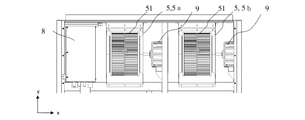
- FIG. 3 is a front view showing the structure of the secondary side region of the heat exchanger 6 of the air conditioner 100 according to the first embodiment.
- FIG. 4 is a front view showing a state in which the fan casing 50 is removed in FIG.
- the secondary side region of the heat exchanger 6 means a region in which the air that has passed through the heat exchanger 6 exists inside the housing 1.
- the primary side region of the heat exchanger 6 means a region in which air exists before passing through the heat exchanger 6. That is, the primary side region is a region upstream of the heat exchanger 6 in the air passage inside the housing 1.
- the secondary side region is a region downstream of the heat exchanger 6 in the air passage inside the housing 1.
- a motor 9, a fan 51 directly connected to the motor 9, and a fan casing 50 that covers the circumference of the fan 51 and is fixed to the top plate 4 are installed.
- two blowers 5a and 5b are arranged in the x direction.
- the control box 8 is arranged side by side with the blower 5 in the horizontal direction of these blowers 5, that is, along the x-axis. Since the control box 8 is arranged on the side of the blower 5, it is not necessary to remove the control box 8 from the air conditioner 100 when the front plate 2 is removed to maintain the area around the blower 5, and maintenance workability is improved. improves.
- the fan casing 50 is divided in the front-rear direction of the air conditioner 100 and is detachably configured, so that maintenance such as cleaning of the internal fan 51 is possible.
- the front-rear direction of the air conditioner 100 is a direction along the z-axis shown in FIGS. 1 and 2.
- a drain pan 7 is arranged in the primary side region of the heat exchanger 6. Dust and dust easily adhere to the heat exchanger 6 and the drain pan 7 due to the condensed water. Therefore, the primary side region of the heat exchanger 6 is frequently cleaned.
- the control box 8 When the control box 8 is installed above the drain pan 7 in the primary side region of the heat exchanger 6 in the air conditioner 100, the control box 8 interferes with the cleaning of the heat exchanger 6 and the drain pan 7, and the cleaning work is performed. It gets complicated. Further, when a large amount of washing water is applied to the control box 8 in the washing work, the water invades the inside of the control box 8. This causes a failure of the air conditioner 100, so that the control box 8 needs to be cured during the cleaning work.
- FIG. 5 is a perspective view showing the appearance of the control box 8 according to the first embodiment.
- FIG. 6 is a perspective view showing a state in which the control box cover 8b is removed from the control box 8 of FIG.
- the control box 8 has an L shape when viewed from the top surface side of the air conditioner 100.
- the control box 8 has an L-shape, and the region on the front side in the z direction is formed wider in the x direction than the region on the back side in the z direction. Therefore, in the control box 8, the boards that are often operated in the field where the air conditioner 100 is installed are arranged on the front side in the control box 8, and the boards that are not operated in the field are on the back side. Have been placed.
- the air conditioner 100 can save space in the arrangement of the control box 8 in the housing 1.
- the terminal block 80 to which the wiring connected to the outside of the control box 8 and the wiring connected to each board is connected is in front of the control box 8 in the z direction. It is located in the area on the side.
- the terminal block mounting portion 8d is screwed and fixed to the control box main body 8a, and is detachably configured from the control box main body 8a. Further, the wiring connecting the terminal block 80 and the boards inside the control box 8 is connected by a connector, and is removable from at least one of the terminal block 80 and the boards.
- the control box left side panel 8e is screwed to the control box main body 8a and is removable.
- the internal wiring has a wiring length with a surplus so that tension is not applied when it is removed.
- FIG. 7 is a cross-sectional view of the air conditioner 100 according to the first embodiment.
- FIG. 7 is a cross-sectional view of the control box 8 as viewed from the blower 5.
- the control box 8 can slide in the front-rear direction of the housing 1, that is, along the z-axis due to the slide structure. Therefore, the control box 8 can be pulled out in the front direction of the housing 1 from which the front plate 2 has been removed during maintenance.
- a slide rail 8f is fixed to the bottom surface of the control box 8.
- the slide rail 8f is formed by bending a plate material so as to have a U-shape, and is welded to the control box main body 8a.
- the slide rail 8f When viewed from the front of the air conditioner 100, the slide rail 8f has two plate-shaped members 8k extending downward from both ends of the plate-shaped joint portion joined to the bottom surface of the control box main body 8a.
- the two plate-shaped members 8k of the slide rail 8f extend in the z direction and are provided with elongated holes 8g on the plate surface arranged in the x direction.
- the housing 1 is provided with a Z-shaped rail 10 in the cross-sectional view of FIG. 7 on the internal beam member 30.
- the rail 10 is fixed to the beam member 30.
- the rail 10 includes a first portion 10a extending in the z direction from the beam member 30, a second portion 10b extending in the y direction from the end of the first portion 10a, and a third portion extending in the z direction from the upper end of the second portion 10b. 10c and.
- the end portion of the third portion 10c in the z direction is a fixed portion 10d.
- the slide rail 8f of the control box 8 and the rail 10 fixed to the housing 1 have a structure that can be fixed by screwing from the side surface. Further, the slide rail 8f of the control box 8 is formed with an elongated hole 8g penetrating the side surface facing the x direction. The elongated hole 8g is formed to have a length corresponding to the slide amount of the control box 8 in the z direction. The control box 8 can be slid along the z-axis by penetrating the elongated hole 8g in the x direction and loosening the screw 8h screwed into the rail 10.
- control box 8 By making the control box 8 slidable in the front-rear direction of the housing 1, the operator can maintain the board without removing the control box 8 from the air conditioner 100. Further, when the front plate 2 of the housing 1 is removed and the inside of the housing 1 is viewed, the area hidden by the control box 8 can be cleaned. Further, when the control box 8 is pulled out toward the front side in the z direction, the control box 8 can be fixed by tightening the screw 8h of the slide rail 8f that has been loosened. There is no need to prepare anything else.
- FIG. 8 is a perspective view of a state in which the control box 8 according to the first embodiment is pulled out.
- the slide rail is used without removing the wiring from the terminal block 80.
- the control box 8 can be pulled out along the 8f.
- the control box left side panel 8e is screwed to the control box main body 8a.
- the left side surface of the control box 8 can be opened.
- access to the substrates inside the control box 8 is facilitated, and the workability of the maintenance of the control box 8 is improved.
- the refrigerant pipe from the outdoor unit (not shown) and the refrigerant pipe of the indoor unit are connected under the drain pan 7.
- Embodiment 2 is a modification of the arrangement and mounting structure of the control box 8 of the air conditioner 100 according to the first embodiment. In the second embodiment, the differences from the first embodiment will be mainly described.
- FIG. 9 is a perspective view of the air conditioner 200 according to the second embodiment with the front plate 2 removed.
- the air conditioner 200 according to the second embodiment has a different arrangement of the control box 8 from the air conditioner 100 according to the first embodiment.
- the control box 208 is arranged in the secondary side region of the heat exchanger 6 and is arranged between the blower 5 and the front plate 2. That is, the control box 208 and the blower 5 are arranged in parallel along the z-axis, and the control box 208 is arranged on the front side in the z direction with respect to the blower 5.
- the inverter board can be cooled while cleaning the heat exchanger 6 and the drain pan 7. It is unlikely that a large amount of water will be applied to the water.
- FIG. 10 is a perspective view of the air conditioner 200 according to the second embodiment with the side panel 3a removed.
- FIG. 10 shows a state seen from the back side, which is the surface opposite to the front side to which the front plate 2 of the housing 1 is attached.
- the heat sink 8c for cooling the inverter board is installed on the side surface 208i facing the blower 5 of the control box 208, and the air passing through the heat exchanger 6 flows. It is configured as follows.
- control box 208 and the housing 1 are connected by a hinge structure in which the control box 208 is rotatable and rotatable.
- the blower 5 installed behind the control box 208 of the housing 1 can be accessed from the front side of the housing 1, and the area around the blower 5 can be easily cleaned.
- a wiring hole for taking the wiring connected to the control box 208 into the control box 208 is provided around the portion where the hinge metal fitting 13 of the control box 208 is arranged.
- the wiring connected to the control box 208 is a motor wiring inside the housing 1 or a sensor wire such as a thermistor.
- the control box 208 can be opened to the outside without making a large surplus in the length of the wiring.
- the pillar 14, the lower beam 11, and the upper beam 12 to which the control box 208 is fixed via the hinge metal fitting 13 may be collectively referred to as a structural member.
- the air conditioner 200 connects the refrigerant pipe from the outdoor unit and the refrigerant pipe of the indoor unit under the drain pan 7 as in the first embodiment. By routing the refrigerant pipe in this way, obstacles above the drain pan 7 are eliminated, and the workability of cleaning the primary side region of the heat exchanger 6 is improved.
Abstract
The purpose of the present disclosure is to provide an air conditioner that does not interfere with the cleaning work inside a housing while ensuring cooling of the interior of a control box. An air conditioner according to the present disclosure comprises: a heat exchanger installed inside a housing; a drain pan disposed below the heat exchanger; a blower disposed above the heat exchanger; and a control box to which the wiring inside the housing is connected. The control box is disposed downstream of the heat exchanger in the air path where the blower and the heat exchanger are arranged.
Description
本開示は、空気調和機の構造に関し、特に制御箱の配置に関する。
This disclosure relates to the structure of the air conditioner, and particularly to the arrangement of the control box.
従来の空気調和機においては、モーターとファンをプーリーとベルトでつながれ、風路と区切られたドレンパンの下側の空間に制御箱を配置した構造が知られている。
In a conventional air conditioner, a structure is known in which a motor and a fan are connected by a pulley and a belt, and a control box is arranged in the space under the drain pan separated from the air passage.
また、冷房や暖房を行うために室内に設置され、モーターとファンとを直結してモーターのインバーター制御を行う空気調和機にあっては、制御箱内に設置されるインバーター基板を冷却する必要がある。例えば、空気調和機は、制御箱のヒートシンクを風路内に配置することにより制御箱内部のインバーター基板の冷却を行っている(例えば特許文献1)。
In addition, in the case of an air conditioner that is installed indoors for cooling and heating and controls the inverter of the motor by directly connecting the motor and fan, it is necessary to cool the inverter board installed in the control box. be. For example, the air conditioner cools the inverter board inside the control box by arranging the heat sink of the control box in the air passage (for example, Patent Document 1).
特許文献1に係る空気調和機は、熱交換器の下流の2次側領域に配置された送風機の前側にインバーター基板を実装している制御箱が配置されている。そして、制御箱は、筐体の梁と四隅でねじ止め固定されており、吹出口が配置されている筐体の正面から見たときに、送風機の一部を隠すように配置されている。このような構造では、筐体の内部のファンやモーターのメンテナンス及びファンなどの洗浄を行う際に、制御箱は、筐体から取り外される必要がある。特に衛生面の管理が厳しい食品工場などでは、空気調和機の内部を定期的に洗浄する。よって、特許文献1に開示されている空気調和機では、洗浄作業が煩雑となり、洗浄作業の効率が下がるという課題があった。
In the air conditioner according to Patent Document 1, a control box on which an inverter board is mounted is arranged on the front side of the blower arranged in the secondary side region downstream of the heat exchanger. The control box is screwed and fixed to the beam of the housing at the four corners, and is arranged so as to hide a part of the blower when viewed from the front of the housing in which the air outlet is arranged. In such a structure, the control box needs to be removed from the housing when the fan and the motor inside the housing are maintained and the fan and the like are cleaned. Especially in food factories where hygiene control is strict, the inside of the air conditioner should be cleaned regularly. Therefore, in the air conditioner disclosed in Patent Document 1, there is a problem that the cleaning work becomes complicated and the efficiency of the cleaning work is lowered.
一方、制御箱を風路外に配置した空気調和機においては、制御箱内に設置したインバーター基板を冷却するためのヒートシンクに風が流れにくく、インバーター基板を冷却することができない。そのため、空気調和機の運転が適切に行うことができないという課題があった。
On the other hand, in an air conditioner in which the control box is placed outside the air passage, it is difficult for wind to flow through the heat sink for cooling the inverter board installed in the control box, and the inverter board cannot be cooled. Therefore, there is a problem that the air conditioner cannot be operated properly.
本開示は、上述の課題を解決するものであり、制御箱の内部の冷却を確保しつつ、筐体内部の洗浄作業を阻害しない空気調和機を提供することを目的とする。
The present disclosure is to solve the above-mentioned problems, and an object of the present invention is to provide an air conditioner that does not hinder the cleaning work inside the housing while ensuring the cooling inside the control box.
本開示の空気調和機は、筐体の内部に設置された熱交換器と、前記熱交換器の下方に設けられたドレンパンと、前記熱交換器の上方に配置された送風機と、前記筐体の内部の配線が接続される制御箱と、を備え、前記制御箱は、前記送風機及び前記熱交換器が配置されている風路において、前記熱交換器よりも下流に配置されている。
The air conditioner of the present disclosure includes a heat exchanger installed inside the housing, a drain pan provided below the heat exchanger, a blower arranged above the heat exchanger, and the housing. The control box is provided with a control box to which the internal wiring of the above is connected, and the control box is arranged downstream of the heat exchanger in the air passage in which the blower and the heat exchanger are arranged.
本開示の空気調和機によれば、上記の様に制御箱が配置されているため、制御箱の内部の基の冷却を確保しつつ、筐体の内部の洗浄時に制御箱が洗浄作業を阻害しない。
According to the air conditioner of the present disclosure, since the control box is arranged as described above, the control box hinders the cleaning work when cleaning the inside of the housing while ensuring the cooling of the base inside the control box. do not do.
実施の形態1.
図1は、実施の形態1に係る空気調和機100を示す斜視図である。図2は、図1の空気調和機100の前板2を取り外した斜視図である。実施の形態1に係る空気調和機100は、筐体1の内部に、送風機5、熱交換器6、及び熱交換器6からの凝縮水を回収するドレンパン7を備える。空気調和機100は、筐体1の前板2bに形成された吸入口20から空気を取り込む。吸入口20の内部には熱交換器6が配置されている。筐体1の内部には、前板2に形成された吸入口20から天板4に形成された吹出口40に至る風路が形成されている。筐体1の内部に取り込まれた空気は、熱交換器6を通過し調和され、筐体1の天板4に形成された吹出口40から吹き出す構造になっている。なお、以下の説明において、筐体1の前板2が配置されている側を前側、前板2と対向する側を背面側、と呼ぶ。また、筐体1の左側及び右側は、筐体1を前板2に向かって見た時の左右に対応している。つまり、x軸の正方向であるx方向が右、x軸に沿った逆向きが左である。なお、xz軸により定義される平面に平行な方向を水平方向、y方向を上とする。Embodiment 1.
FIG. 1 is a perspective view showing anair conditioner 100 according to the first embodiment. FIG. 2 is a perspective view with the front plate 2 of the air conditioner 100 of FIG. 1 removed. The air conditioner 100 according to the first embodiment includes a blower 5, a heat exchanger 6, and a drain pan 7 for recovering condensed water from the heat exchanger 6 inside the housing 1. The air conditioner 100 takes in air from the suction port 20 formed in the front plate 2b of the housing 1. A heat exchanger 6 is arranged inside the suction port 20. Inside the housing 1, an air passage is formed from the suction port 20 formed on the front plate 2 to the air outlet 40 formed on the top plate 4. The air taken into the inside of the housing 1 passes through the heat exchanger 6 and is harmonized, and has a structure of being blown out from the air outlet 40 formed in the top plate 4 of the housing 1. In the following description, the side of the housing 1 where the front plate 2 is arranged is referred to as a front side, and the side facing the front plate 2 is referred to as a back side. Further, the left side and the right side of the housing 1 correspond to the left and right when the housing 1 is viewed toward the front plate 2. That is, the x-direction, which is the positive direction of the x-axis, is the right, and the reverse direction along the x-axis is the left. The direction parallel to the plane defined by the xz axis is the horizontal direction, and the y direction is the top.
図1は、実施の形態1に係る空気調和機100を示す斜視図である。図2は、図1の空気調和機100の前板2を取り外した斜視図である。実施の形態1に係る空気調和機100は、筐体1の内部に、送風機5、熱交換器6、及び熱交換器6からの凝縮水を回収するドレンパン7を備える。空気調和機100は、筐体1の前板2bに形成された吸入口20から空気を取り込む。吸入口20の内部には熱交換器6が配置されている。筐体1の内部には、前板2に形成された吸入口20から天板4に形成された吹出口40に至る風路が形成されている。筐体1の内部に取り込まれた空気は、熱交換器6を通過し調和され、筐体1の天板4に形成された吹出口40から吹き出す構造になっている。なお、以下の説明において、筐体1の前板2が配置されている側を前側、前板2と対向する側を背面側、と呼ぶ。また、筐体1の左側及び右側は、筐体1を前板2に向かって見た時の左右に対応している。つまり、x軸の正方向であるx方向が右、x軸に沿った逆向きが左である。なお、xz軸により定義される平面に平行な方向を水平方向、y方向を上とする。
FIG. 1 is a perspective view showing an
熱交換器6は、筐体1の前板2が配置されている側から見て、吸入口20の裏側に配置されている。送風機5は、2つの送風機5a及び5bを含み、熱交換器6の上方に配置されており、吹出口40と熱交換器6との間に位置している。送風機5は、ファン51(図4参照)とモーター9(図3参照)とが連結されており、モーター9をインバーター制御してファン51を駆動している。吸入口20から流入した空気は、筐体1の内部において傾斜して配置されている熱交換器6を通過して筐体1の内部を上方に流れる。熱交換器6を通過した空気は、送風機5のファンケーシング50の内部に流入し、ファン51により吹出口40から吹き出される。ドレンパン7は、筐体1の内部において傾斜して配置されている熱交換器6の下方で流下する水分を捕集できるように配置されている。なお、実施の形態1において、ファン51はシロッコファンにより構成されている。
The heat exchanger 6 is arranged on the back side of the suction port 20 when viewed from the side where the front plate 2 of the housing 1 is arranged. The blower 5 includes two blowers 5a and 5b, is located above the heat exchanger 6 and is located between the outlet 40 and the heat exchanger 6. In the blower 5, a fan 51 (see FIG. 4) and a motor 9 (see FIG. 3) are connected to each other, and the motor 9 is controlled by an inverter to drive the fan 51. The air that has flowed in from the suction port 20 passes through the heat exchanger 6 that is inclined and arranged inside the housing 1, and flows upward inside the housing 1. The air that has passed through the heat exchanger 6 flows into the inside of the fan casing 50 of the blower 5, and is blown out from the outlet 40 by the fan 51. The drain pan 7 is arranged so as to be able to collect the water flowing down below the heat exchanger 6 which is inclined and arranged inside the housing 1. In the first embodiment, the fan 51 is composed of a sirocco fan.
図3は、実施の形態1に係る空気調和機100の熱交換器6の2次側領域の構造を示す正面図である。図4は、図3においてファンケーシング50を取り外した状態の正面図である。ここで、熱交換器6の2次側領域とは、筐体1の内部において熱交換器6を通過した空気が存在する領域を意味する。なお、熱交換器6の1次側領域は、熱交換器6を通過する前の空気が存在する領域を意味する。つまり、1次側領域は、筐体1の内部の風路において熱交換器6よりも上流の領域である。2次側領域は、筐体1の内部の風路において熱交換器6よりも下流の領域である。
FIG. 3 is a front view showing the structure of the secondary side region of the heat exchanger 6 of the air conditioner 100 according to the first embodiment. FIG. 4 is a front view showing a state in which the fan casing 50 is removed in FIG. Here, the secondary side region of the heat exchanger 6 means a region in which the air that has passed through the heat exchanger 6 exists inside the housing 1. The primary side region of the heat exchanger 6 means a region in which air exists before passing through the heat exchanger 6. That is, the primary side region is a region upstream of the heat exchanger 6 in the air passage inside the housing 1. The secondary side region is a region downstream of the heat exchanger 6 in the air passage inside the housing 1.
熱交換器6の2次側領域は、モーター9と、モーター9に直結されたファン51と、ファン51の周囲を覆い天板4に固定されたファンケーシング50と、が設置されている。実施の形態1においては、x方向に2つの送風機5a及び5bが並べられている。制御箱8は、これらの送風機5の水平方向、即ちx軸に沿って送風機5と共に並べて配置されている。送風機5の側方に制御箱8が配置されているため、前板2を取り外して送風機5周辺をメンテナンスする際に、制御箱8を空気調和機100から取り外す必要が無く、メンテナンスの作業性が向上する。また、制御箱8の配線取出し口(図示なし)及びモーター9を養生すれば、送風機5周辺の洗浄も容易に行える。なお、実施の形態1において、ファンケーシング50は、空気調和機100の前後方向に分割して取り外し自在に構成されているため、内部のファン51の洗浄などのメンテンナンスが可能である。ここで、空気調和機100の前後方向とは、図1及び図2に示されているz軸に沿った方向である。
In the secondary side region of the heat exchanger 6, a motor 9, a fan 51 directly connected to the motor 9, and a fan casing 50 that covers the circumference of the fan 51 and is fixed to the top plate 4 are installed. In the first embodiment, two blowers 5a and 5b are arranged in the x direction. The control box 8 is arranged side by side with the blower 5 in the horizontal direction of these blowers 5, that is, along the x-axis. Since the control box 8 is arranged on the side of the blower 5, it is not necessary to remove the control box 8 from the air conditioner 100 when the front plate 2 is removed to maintain the area around the blower 5, and maintenance workability is improved. improves. Further, if the wiring outlet (not shown) of the control box 8 and the motor 9 are cured, the area around the blower 5 can be easily cleaned. In the first embodiment, the fan casing 50 is divided in the front-rear direction of the air conditioner 100 and is detachably configured, so that maintenance such as cleaning of the internal fan 51 is possible. Here, the front-rear direction of the air conditioner 100 is a direction along the z-axis shown in FIGS. 1 and 2.
熱交換器6の1次側領域には、ドレンパン7が配置されている。熱交換器6及びドレンパン7は、凝縮水で粉塵やゴミなどが付着しやすい。そのため、熱交換器6の1次側領域は、洗浄頻度が高い。空気調和機100において熱交換器6の1次側領域であってドレンパン7の上方に制御箱8を設置した場合、制御箱8が熱交換器6及びドレンパン7の洗浄の妨げとなり、洗浄作業が煩雑になる。また、洗浄作業において制御箱8に洗浄水が大量にかかると制御箱8の内部に水が侵入する。これにより空気調和機100の故障の原因となるため、洗浄作業の際には、制御箱8の養生が必要となる。実施の形態1に係る制御箱8は、洗浄頻度が高い1次側領域ではなく、2次側領域に配置されることにより、空気調和機100のメンテナンス作業を容易にできる。また、制御箱8は、2次側領域に配置されることにより、冷却の効率も高くできる。
A drain pan 7 is arranged in the primary side region of the heat exchanger 6. Dust and dust easily adhere to the heat exchanger 6 and the drain pan 7 due to the condensed water. Therefore, the primary side region of the heat exchanger 6 is frequently cleaned. When the control box 8 is installed above the drain pan 7 in the primary side region of the heat exchanger 6 in the air conditioner 100, the control box 8 interferes with the cleaning of the heat exchanger 6 and the drain pan 7, and the cleaning work is performed. It gets complicated. Further, when a large amount of washing water is applied to the control box 8 in the washing work, the water invades the inside of the control box 8. This causes a failure of the air conditioner 100, so that the control box 8 needs to be cured during the cleaning work. By arranging the control box 8 according to the first embodiment not in the primary side region where the cleaning frequency is high but in the secondary side region, the maintenance work of the air conditioner 100 can be facilitated. Further, by arranging the control box 8 in the secondary side region, the cooling efficiency can be increased.
図5は、実施の形態1に係る制御箱8の外観を示す斜視図である。図6は、図5の制御箱8から制御箱カバー8bを取り外した状態の斜視図である。制御箱8は、空気調和機100の天面側から見たときにL字形状となっている。制御箱8は、L字形状となっており、z方向における手前側の領域がz方向おける奥側の領域よりもx方向に広く形成されている。従って、制御箱8は、空気調和機100が設置されている現地で操作することが多い基板類が制御箱8内の手前側に配置され、現地で操作することがない基板類が奥側に配置されている。制御箱8の内部においてこのように基板類を配置することにより、現地での作業スペースを確保しつつ、制御箱8の小型化が可能となる。つまり、空気調和機100は、筐体1内において制御箱8の配置の省スペース化を図ることができる。図6に示される様に、実施の形態1においては、制御箱8の外部と接続する配線及び各基板類と接続する配線が接続されている端子台80が、制御箱8のz方向の手前側の領域に配置されている。
FIG. 5 is a perspective view showing the appearance of the control box 8 according to the first embodiment. FIG. 6 is a perspective view showing a state in which the control box cover 8b is removed from the control box 8 of FIG. The control box 8 has an L shape when viewed from the top surface side of the air conditioner 100. The control box 8 has an L-shape, and the region on the front side in the z direction is formed wider in the x direction than the region on the back side in the z direction. Therefore, in the control box 8, the boards that are often operated in the field where the air conditioner 100 is installed are arranged on the front side in the control box 8, and the boards that are not operated in the field are on the back side. Have been placed. By arranging the substrates in this way inside the control box 8, it is possible to reduce the size of the control box 8 while securing a work space at the site. That is, the air conditioner 100 can save space in the arrangement of the control box 8 in the housing 1. As shown in FIG. 6, in the first embodiment, the terminal block 80 to which the wiring connected to the outside of the control box 8 and the wiring connected to each board is connected is in front of the control box 8 in the z direction. It is located in the area on the side.
制御箱8の送風機5に対向している側面8iには、ヒートシンク8cが設置されている。ヒートシンク8cは、送風機5に近い側面8iに設置されているため、送風機5に向かって流れる空気の一部をヒートシンク8cに流すことができる。これにより、制御箱8の内部に設置されているインバーター基板(図示なし)を冷却できる。また、送風機5周辺の洗浄の際に、ヒートシンク8cも洗浄することができる。そのため、ヒートシンク8cに汚れが堆積することによる冷却効果の低下を抑えられる。制御箱本体8aは、例えば板金部材を組み合わせて箱体となっている。制御箱本体8aは、ヒートシンク8cの周囲の隙間にシリコンコーキングを充填して水の侵入を防いでいる。これにより、板金部材を組み合わせた制御箱本体8aの外側に設置されているヒートシンク8cの洗浄ができる。
A heat sink 8c is installed on the side surface 8i of the control box 8 facing the blower 5. Since the heat sink 8c is installed on the side surface 8i near the blower 5, a part of the air flowing toward the blower 5 can flow to the heat sink 8c. As a result, the inverter board (not shown) installed inside the control box 8 can be cooled. Further, when cleaning the area around the blower 5, the heat sink 8c can also be cleaned. Therefore, it is possible to suppress a decrease in the cooling effect due to the accumulation of dirt on the heat sink 8c. The control box main body 8a is formed into a box by combining, for example, sheet metal members. The control box main body 8a is filled with silicon caulking in the gap around the heat sink 8c to prevent water from entering. This makes it possible to clean the heat sink 8c installed on the outside of the control box main body 8a in which the sheet metal member is combined.
端子台取付部8dは、制御箱本体8aとねじ止め固定されており、制御箱本体8aから着脱自在に構成されている。また、端子台80と制御箱8の内部の基板類とを繋ぐ配線はコネクターにより接続されており、端子台80及び基板類の少なくとも一方から取り外し可能となっている。制御箱左側面パネル8eは制御箱本体8aとねじ止めされており取り外し可能である。また、内部の配線は取り外した時に張力が掛からないように余剰を持った配線長さとしている。
The terminal block mounting portion 8d is screwed and fixed to the control box main body 8a, and is detachably configured from the control box main body 8a. Further, the wiring connecting the terminal block 80 and the boards inside the control box 8 is connected by a connector, and is removable from at least one of the terminal block 80 and the boards. The control box left side panel 8e is screwed to the control box main body 8a and is removable. In addition, the internal wiring has a wiring length with a surplus so that tension is not applied when it is removed.
図7は、実施の形態1に係る空気調和機100の断面図である。図7は、送風機5から制御箱8を見た状態の断面図である。実施の形態1においては、制御箱8は、スライド構造により、筐体1の前後方向、つまりz軸に沿ってスライドできる。従って、制御箱8は、メンテナンスの際、前板2を取り外した筐体1の前方向に引き出し可能である。制御箱8の底面にはスライドレール8fが固定されている。スライドレール8fは、コの字形状になるように板材を折り曲げて形成され、制御箱本体8aに溶接されている。スライドレール8fは、空気調和機100の正面から見たときに、制御箱本体8aの底面に接合されている板状の接合部の両端から下方に2つの板状部材8kが延びている。スライドレール8fの2つの板状部材8kは、z方向に延び、x方向に向けて配置された板面に長孔8gを設けたものである。
FIG. 7 is a cross-sectional view of the air conditioner 100 according to the first embodiment. FIG. 7 is a cross-sectional view of the control box 8 as viewed from the blower 5. In the first embodiment, the control box 8 can slide in the front-rear direction of the housing 1, that is, along the z-axis due to the slide structure. Therefore, the control box 8 can be pulled out in the front direction of the housing 1 from which the front plate 2 has been removed during maintenance. A slide rail 8f is fixed to the bottom surface of the control box 8. The slide rail 8f is formed by bending a plate material so as to have a U-shape, and is welded to the control box main body 8a. When viewed from the front of the air conditioner 100, the slide rail 8f has two plate-shaped members 8k extending downward from both ends of the plate-shaped joint portion joined to the bottom surface of the control box main body 8a. The two plate-shaped members 8k of the slide rail 8f extend in the z direction and are provided with elongated holes 8g on the plate surface arranged in the x direction.
筐体1は、内部の梁部材30に図7の断面図においてZ形状のレール10を備える。レール10は、梁部材30に固定されている。レール10は、梁部材30からz方向に延びる第1部分10aと、第1部分10aの端部からy方向に延びる第2部分10bと、第2部分10bの上端からz方向に延びる第3部分10cと、を備える。第3部分10cのz方向の端部は、固定部10dとなっている。第1部分10a及び第2部分10bのように、レール10のz方向側の部分が制御箱8から下方に離れて位置しているため、制御箱8のz方向側の制御箱本体8aの底部に形成されている端子台取付部8dの下方に配線取り回し用のスペースが確保できる。言い換えると、制御箱8が引き出される方向のレール10の一部が制御箱8の底面から下方に離れて形成されたレール10は、端子台取付部8dの下方に配線取り回し用のスペースを形成している。
The housing 1 is provided with a Z-shaped rail 10 in the cross-sectional view of FIG. 7 on the internal beam member 30. The rail 10 is fixed to the beam member 30. The rail 10 includes a first portion 10a extending in the z direction from the beam member 30, a second portion 10b extending in the y direction from the end of the first portion 10a, and a third portion extending in the z direction from the upper end of the second portion 10b. 10c and. The end portion of the third portion 10c in the z direction is a fixed portion 10d. Since the portion of the rail 10 on the z-direction side is located downward from the control box 8 as in the first portion 10a and the second portion 10b, the bottom portion of the control box main body 8a on the z-direction side of the control box 8 is located. A space for wiring can be secured below the terminal block mounting portion 8d formed in. In other words, the rail 10 formed so that a part of the rail 10 in the direction in which the control box 8 is pulled out is separated downward from the bottom surface of the control box 8 forms a space for wiring under the terminal block mounting portion 8d. ing.
制御箱8のスライドレール8fと筐体1に固定されたレール10とは、側面からねじ止めして固定できる構造となっている。また、制御箱8のスライドレール8fは、x方向を向いた側面に貫通する長孔8gが形成されている。長孔8gは、z方向において制御箱8のスライド量に応じた長さに形成されている。x方向に長孔8gを貫通し、レール10にねじ込まれているねじ8hを緩めることで、制御箱8は、z軸に沿ってスライドできる。
The slide rail 8f of the control box 8 and the rail 10 fixed to the housing 1 have a structure that can be fixed by screwing from the side surface. Further, the slide rail 8f of the control box 8 is formed with an elongated hole 8g penetrating the side surface facing the x direction. The elongated hole 8g is formed to have a length corresponding to the slide amount of the control box 8 in the z direction. The control box 8 can be slid along the z-axis by penetrating the elongated hole 8g in the x direction and loosening the screw 8h screwed into the rail 10.
制御箱8を筐体1の前後方向にスライドできる構造とすることで、作業者は、制御箱8を空気調和機100から降ろすことなく基板のメンテナンスを行える。また、筐体1の前板2を外して筐体1の内部を見た際に、制御箱8で隠れている領域の洗浄が可能となる。また、制御箱8をz方向手前側に引き出した際に、緩めておいたスライドレール8fのねじ8hを締めることにより、制御箱8を固定できるため、メンテナンス時に制御箱8を固定する台などを他に用意する必要が無い。
By making the control box 8 slidable in the front-rear direction of the housing 1, the operator can maintain the board without removing the control box 8 from the air conditioner 100. Further, when the front plate 2 of the housing 1 is removed and the inside of the housing 1 is viewed, the area hidden by the control box 8 can be cleaned. Further, when the control box 8 is pulled out toward the front side in the z direction, the control box 8 can be fixed by tightening the screw 8h of the slide rail 8f that has been loosened. There is no need to prepare anything else.
図8は、実施の形態1に係る制御箱8を引き出した状態の斜視図である。制御箱本体8aに端子台取付部8dを固定しているねじ及び端子台80と制御箱8内の他の基板類とを繋ぐコネクターを取り外すと、配線を端子台80から取り外すことなく、スライドレール8fに沿って制御箱8を手前に引き出すことができる。また、制御箱左側面パネル8eは制御箱本体8aにねじ止めされている。制御箱8を引き出し、制御箱左側面パネル8eを取り外すと、制御箱8の左側面を開くことができる。制御箱8を引き出した状態で制御箱8の左側面を開くことにより、制御箱8の内部の基板類へのアクセスを容易にし、制御箱8のメンテンナンスの作業性が向上する。
FIG. 8 is a perspective view of a state in which the control box 8 according to the first embodiment is pulled out. When the screw that fixes the terminal block mounting portion 8d to the control box body 8a and the connector that connects the terminal block 80 and other boards in the control box 8 are removed, the slide rail is used without removing the wiring from the terminal block 80. The control box 8 can be pulled out along the 8f. Further, the control box left side panel 8e is screwed to the control box main body 8a. By pulling out the control box 8 and removing the control box left side panel 8e, the left side surface of the control box 8 can be opened. By opening the left side surface of the control box 8 with the control box 8 pulled out, access to the substrates inside the control box 8 is facilitated, and the workability of the maintenance of the control box 8 is improved.
制御箱8の端子台取付部8dと制御箱本体8aとの合わせ面、制御箱左側面パネル8eと制御箱本体8aとの合わせ面及び制御箱カバー8bと制御箱本体8aの合わせ面は、シール材を貼り付けてある。シール材は、送風機5を洗浄する際に制御箱8に水が掛かっても制御箱8の内部への水の浸入を防止する。制御箱8の配線取り込み口8jには配線を包むような形状のゴムブッシュが配置されている。配線が内部に通されたゴムブッシュを結束部材により外周から括ることにより、配線取り込み口8jからの水及びゴミ等が制御箱8内への侵入するのを防止する。
The mating surface between the terminal block mounting portion 8d of the control box 8 and the control box main body 8a, the mating surface between the control box left side panel 8e and the control box main body 8a, and the mating surface between the control box cover 8b and the control box main body 8a are sealed. The material is pasted. The sealing material prevents water from entering the inside of the control box 8 even if the control box 8 is splashed with water when the blower 5 is washed. A rubber bush having a shape that wraps the wiring is arranged at the wiring intake port 8j of the control box 8. By tying the rubber bush through which the wiring is passed from the outer circumference with a binding member, it is possible to prevent water, dust, etc. from the wiring intake port 8j from entering the control box 8.
実施の形態1に係る空気調和機100は、室外機(図示なし)からの冷媒配管と室内機の冷媒配管の接続をドレンパン7の下側で行っている。このように冷媒配管を引き回すことにより、ドレンパン7の上方に障害物がなく、熱交換器6の一次側領域の洗浄をする際の作業性が向上する。
In the air conditioner 100 according to the first embodiment, the refrigerant pipe from the outdoor unit (not shown) and the refrigerant pipe of the indoor unit are connected under the drain pan 7. By routing the refrigerant pipe in this way, there are no obstacles above the drain pan 7, and workability when cleaning the primary side region of the heat exchanger 6 is improved.
実施の形態2.
実施の形態2は、実施の形態1に係る空気調和機100の制御箱8の配置及び取付構造を変更したものである。実施の形態2においては、実施の形態1に対する相違点を中心に説明する。 Embodiment 2.
The second embodiment is a modification of the arrangement and mounting structure of thecontrol box 8 of the air conditioner 100 according to the first embodiment. In the second embodiment, the differences from the first embodiment will be mainly described.
実施の形態2は、実施の形態1に係る空気調和機100の制御箱8の配置及び取付構造を変更したものである。実施の形態2においては、実施の形態1に対する相違点を中心に説明する。 Embodiment 2.
The second embodiment is a modification of the arrangement and mounting structure of the
図9は、実施の形態2に係る空気調和機200の前板2を取り外した状態の斜視図である。実施の形態2に係る空気調和機200は、実施形態1に係る空気調和機100とは制御箱8の配置が異なる。実施の形態2に係る空気調和機200においては、制御箱208は、熱交換器6の2次側領域に配置され、送風機5と前板2との間に配置されている。つまり、制御箱208と送風機5とは、z軸に沿って並列しており、制御箱208が送風機5よりもz方向手前側に配置されている。制御箱208は、実施形態1の空気調和機100と同様に熱交換器6の2次側に配置することで、インバーター基板の冷却を可能としながら、熱交換器6やドレンパン7の洗浄の際に水が大量にかかることが少ない。
FIG. 9 is a perspective view of the air conditioner 200 according to the second embodiment with the front plate 2 removed. The air conditioner 200 according to the second embodiment has a different arrangement of the control box 8 from the air conditioner 100 according to the first embodiment. In the air conditioner 200 according to the second embodiment, the control box 208 is arranged in the secondary side region of the heat exchanger 6 and is arranged between the blower 5 and the front plate 2. That is, the control box 208 and the blower 5 are arranged in parallel along the z-axis, and the control box 208 is arranged on the front side in the z direction with respect to the blower 5. By arranging the control box 208 on the secondary side of the heat exchanger 6 in the same manner as the air conditioner 100 of the first embodiment, the inverter board can be cooled while cleaning the heat exchanger 6 and the drain pan 7. It is unlikely that a large amount of water will be applied to the water.
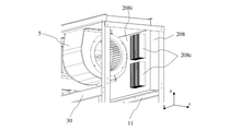
図10は、実施の形態2に係る空気調和機200のサイドパネル3aを外した状態の斜視図である。図10は、筐体1の前板2が取り付けられている正面に対し反対側の面である背面側から見た状態を示している。図10に示されている様に、制御箱208は、インバーター基板を冷却するヒートシンク8cが制御箱208の送風機5と対向する側面208iに設置されており、熱交換器6を通過した空気が流れるように構成されている。
FIG. 10 is a perspective view of the air conditioner 200 according to the second embodiment with the side panel 3a removed. FIG. 10 shows a state seen from the back side, which is the surface opposite to the front side to which the front plate 2 of the housing 1 is attached. As shown in FIG. 10, in the control box 208, the heat sink 8c for cooling the inverter board is installed on the side surface 208i facing the blower 5 of the control box 208, and the air passing through the heat exchanger 6 flows. It is configured as follows.
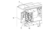
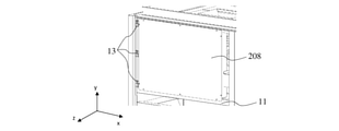
図11は、実施の形態2の筐体1に取り付けられた状態の制御箱208の斜視図である。図12は、図11の制御箱208をユニット前方へ開いた状態の斜視図である。図11において、制御箱208の左側の端と筐体1の左前側の柱14とは、ヒンジ金具13を介して連結されている。制御箱208は下側梁11と上側梁12にねじ止めして固定されている。送風機5の周辺を洗浄する際は、制御箱208と下側梁11及び上側梁12とを留めているねじを取り外す。そして、制御箱208をヒンジ金具13の周りに回転させて制御箱208を筐体1の外側に向かって開く。つまり、制御箱208と筐体1とは、制御箱208が回転移動自在なヒンジ構造により接続されている。これにより、筐体1の制御箱208の後ろ側に設置された送風機5に筐体1の正面側からアクセスでき、送風機5の周辺の洗浄が容易となる。また、制御箱208に接続される配線を制御箱208内へ取り込む配線穴が制御箱208のヒンジ金具13が配置されている部分の周辺に設けている。制御箱208に接続される配線とは、筐体1の内部のモータ配線やサーミスタ等のセンサー線である。配線穴をヒンジ金具13の近傍とすることにより、配線の長さに余剰を大きくとらずとも、制御箱208を外側に開くことができる。なお、制御箱208がヒンジ金具13を介して固定されている柱14、下側梁11及び上側梁12を総称して構造部材と称する場合がある。
FIG. 11 is a perspective view of the control box 208 in a state of being attached to the housing 1 of the second embodiment. FIG. 12 is a perspective view showing a state in which the control box 208 of FIG. 11 is opened to the front of the unit. In FIG. 11, the left end of the control box 208 and the left front pillar 14 of the housing 1 are connected via a hinge metal fitting 13. The control box 208 is fixed to the lower beam 11 and the upper beam 12 by screwing. When cleaning the periphery of the blower 5, the screws holding the control box 208 and the lower beam 11 and the upper beam 12 are removed. Then, the control box 208 is rotated around the hinge fitting 13 to open the control box 208 toward the outside of the housing 1. That is, the control box 208 and the housing 1 are connected by a hinge structure in which the control box 208 is rotatable and rotatable. As a result, the blower 5 installed behind the control box 208 of the housing 1 can be accessed from the front side of the housing 1, and the area around the blower 5 can be easily cleaned. Further, a wiring hole for taking the wiring connected to the control box 208 into the control box 208 is provided around the portion where the hinge metal fitting 13 of the control box 208 is arranged. The wiring connected to the control box 208 is a motor wiring inside the housing 1 or a sensor wire such as a thermistor. By setting the wiring hole in the vicinity of the hinge metal fitting 13, the control box 208 can be opened to the outside without making a large surplus in the length of the wiring. The pillar 14, the lower beam 11, and the upper beam 12 to which the control box 208 is fixed via the hinge metal fitting 13 may be collectively referred to as a structural member.
実施の形態2においては、制御箱208がヒンジ構造により回転移動でき、送風機5の洗浄時には、制御箱208を筐体1の外側に開いて退避する。そのため、洗浄水が制御箱208に掛かることが無く、制御箱208は、制御箱208の内部に水が浸入しないような水密構造でなくともよい。この場合、ヒートシンク8cが汚れているときには、制御箱208を外側に開いた状態で湿らせたウエスなどを用いて拭き取り清掃を行う。
In the second embodiment, the control box 208 can be rotated and moved by the hinge structure, and when the blower 5 is cleaned, the control box 208 is opened to the outside of the housing 1 and retracted. Therefore, the washing water does not hang on the control box 208, and the control box 208 does not have to have a watertight structure so that water does not enter the inside of the control box 208. In this case, when the heat sink 8c is dirty, the control box 208 is wiped off and cleaned with a damp cloth with the control box 208 open to the outside.
また、実施の形態2においても、空気調和機200は、実施の形態1と同様に室外機からの冷媒配管と室内機の冷媒配管の接続をドレンパン7の下側で行っている。このように冷媒配管を引き回すことにより、ドレンパン7の上方の障害物を無くして、熱交換器6の1次側領域の洗浄の作業性が向上する。
Further, also in the second embodiment, the air conditioner 200 connects the refrigerant pipe from the outdoor unit and the refrigerant pipe of the indoor unit under the drain pan 7 as in the first embodiment. By routing the refrigerant pipe in this way, obstacles above the drain pan 7 are eliminated, and the workability of cleaning the primary side region of the heat exchanger 6 is improved.
1 筐体、2 前板、2b 前板、3a サイドパネル、4 天板、5 送風機、5a 送風機、6 熱交換器、7 ドレンパン、8 制御箱、8a 制御箱本体、8b 制御箱カバー、8c ヒートシンク、8d 端子台取付部、8e 制御箱左側面パネル、8f スライドレール、8g 長孔、8h ねじ、8i 側面、8j 配線取り込み口、8k 板状部材、9 モーター、10 レール、10a 第1部分、10b 第2部分、10c 第3部分、10d 固定部、11 下側梁、12 上側梁、13 ヒンジ金具、14 柱、20 吸入口、30 梁部材、40 吹出口、50 ファンケーシング、51 ファン、80 端子台、100 空気調和機、200 空気調和機、208 制御箱、208i 側面。
1 housing, 2 front plate, 2b front plate, 3a side panel, 4 top plate, 5 blower, 5a blower, 6 heat exchanger, 7 drain pan, 8 control box, 8a control box body, 8b control box cover, 8c heat sink , 8d terminal block mounting part, 8e control box left side panel, 8f slide rail, 8g long hole, 8h screw, 8i side surface, 8j wiring intake port, 8k plate-shaped member, 9 motor, 10 rail, 10a first part, 10b 2nd part, 10c, 3rd part, 10d fixed part, 11 lower beam, 12 upper beam, 13 hinge metal fittings, 14 pillars, 20 suction ports, 30 beam members, 40 outlets, 50 fan casings, 51 fans, 80 terminals Platform, 100 air conditioner, 200 air conditioner, 208 control box, 208i side.
Claims (12)
- 筐体の内部に設置された熱交換器と、
前記熱交換器の下方に設けられたドレンパンと、
前記熱交換器の上方に配置された送風機と、
前記筐体の内部の配線が接続される制御箱と、を備え、
前記制御箱は、
前記送風機及び前記熱交換器が配置されている風路において、前記熱交換器よりも下流に配置されている、空気調和機。 The heat exchanger installed inside the housing and
The drain pan provided below the heat exchanger and
The blower located above the heat exchanger and
A control box to which the wiring inside the housing is connected is provided.
The control box is
An air conditioner arranged downstream of the heat exchanger in the air passage in which the blower and the heat exchanger are arranged. - 前記制御箱は、
前記送風機の水平方向に並べて配置されている、請求項1に記載の空気調和機。 The control box is
The air conditioner according to claim 1, wherein the blowers are arranged side by side in the horizontal direction. - 前記制御箱は、
内部に配置された基板を冷却するヒートシンクを備え、
前記ヒートシンクは
前記制御箱の前記送風機と対向する面に設置されている、請求項1又は請求項2に記載の空気調和機。 The control box is
Equipped with a heat sink to cool the board placed inside
The air conditioner according to claim 1 or 2, wherein the heat sink is installed on a surface of the control box facing the blower. - 前記制御箱は、
水平方向に動かせるスライド構造を備える、請求項1~請求項3の何れか1項に記載の空気調和機。 The control box is
The air conditioner according to any one of claims 1 to 3, further comprising a slide structure that can be moved in the horizontal direction. - 前記スライド構造は、
前記筐体の梁に固定されたレールと、
前記制御箱の底面に固定されたスライドレールと、を備え、
前記スライドレールは、
前記筐体の前後方向に沿って延び、水平方向に貫通する長孔が形成され、
前記長孔は、
前記レールに螺合して固定されたねじが挿通され、
前記制御箱は、
前記筐体の前方向に引き出し可能である、請求項4に記載の空気調和機。 The slide structure is
The rail fixed to the beam of the housing and
With a slide rail fixed to the bottom of the control box,
The slide rail
An elongated hole extending along the front-rear direction of the housing and penetrating in the horizontal direction is formed.
The long hole is
A screw screwed and fixed to the rail is inserted and inserted.
The control box is
The air conditioner according to claim 4, which can be pulled out in the front direction of the housing. - 前記制御箱は、
前記筐体の前側の下部に着脱自在に固定された端子台取付部を備え、
前記端子台取付部は、
前記制御箱の内部に配置された基板に接続する配線が着脱自在に接続されている端子台が固定され、
前記端子台は
前記制御箱の外部からの配線が接続されている、請求項4又は請求項5に記載の空気調和機。 The control box is
A terminal block mounting part that is detachably fixed at the lower part of the front side of the housing is provided.
The terminal block mounting portion is
The terminal block to which the wiring connected to the board arranged inside the control box is detachably connected is fixed.
The air conditioner according to claim 4 or 5, wherein the terminal block is connected to wiring from the outside of the control box. - 前記制御箱は、
前記端子台取付部と前記端子台取付部が固定されている制御箱本体との合わせ面に挟まれて配置されたシール材を備える、請求項6に記載の空気調和機。 The control box is
The air conditioner according to claim 6, further comprising a sealing material sandwiched between a mating surface of the terminal block mounting portion and a control box main body to which the terminal block mounting portion is fixed. - 前記制御箱は、
前記送風機の水平方向であって、前記送風機と前記筐体の前板との間に配置され、
前記筐体の内部にヒンジ構造を介して取り付けられ、前記ヒンジ構造を中心に前記筐体の外側に回動する、請求項1~請求項3の何れか1項に記載の空気調和機。 The control box is
Located in the horizontal direction of the blower and between the blower and the front plate of the housing.
The air conditioner according to any one of claims 1 to 3, which is attached to the inside of the housing via a hinge structure and rotates to the outside of the housing around the hinge structure. - 前記ヒンジ構造は、
前記制御箱の水平方向の端部と前記筐体の構造部材とを連結し、
前記制御箱は、
前記ヒンジ構造が配置されている端部において配線が前記制御箱の内部に引き込まれる、請求項8に記載の空気調和機。 The hinge structure is
The horizontal end of the control box and the structural member of the housing are connected to each other.
The control box is
The air conditioner according to claim 8, wherein the wiring is drawn into the control box at the end where the hinge structure is arranged. - 前記送風機は、
内部にファンが配置されるファンケーシングを備え、
前記ファンケーシングは、
前記筐体の前後方向に分割して取り外し自在である、請求項1~請求項9の何れか1項に記載の空気調和機。 The blower is
Equipped with a fan casing in which the fan is placed
The fan casing is
The air conditioner according to any one of claims 1 to 9, which is split and removable in the front-rear direction of the housing. - 前記ドレンパンの下方に冷媒配管が引き回され、
前記冷媒配管は、
前記筐体の外部に配置された室外機からの配管と接続される、請求項1~請求項10の何れか1項に記載の空気調和機。 A refrigerant pipe is routed under the drain pan,
The refrigerant pipe is
The air conditioner according to any one of claims 1 to 10, which is connected to a pipe from an outdoor unit arranged outside the housing. - 前記送風機は、
モーターとファンとを備え、
前記モーターと前記ファンとが連結しており、
前記モーターは、
インバーター制御により駆動される、請求項1~請求項11の何れか1項に記載の空気調和機。 The blower is
Equipped with a motor and a fan,
The motor and the fan are connected to each other.
The motor is
The air conditioner according to any one of claims 1 to 11, which is driven by inverter control.
Priority Applications (2)
| Application Number | Priority Date | Filing Date | Title |
|---|---|---|---|
| PCT/JP2020/029840 WO2022029891A1 (en) | 2020-08-04 | 2020-08-04 | Air conditioner |
| JP2022541378A JP7459258B2 (en) | 2020-08-04 | 2020-08-04 | air conditioner |
Applications Claiming Priority (1)
| Application Number | Priority Date | Filing Date | Title |
|---|---|---|---|
| PCT/JP2020/029840 WO2022029891A1 (en) | 2020-08-04 | 2020-08-04 | Air conditioner |
Publications (1)
| Publication Number | Publication Date |
|---|---|
| WO2022029891A1 true WO2022029891A1 (en) | 2022-02-10 |
Family
ID=80117766
Family Applications (1)
| Application Number | Title | Priority Date | Filing Date |
|---|---|---|---|
| PCT/JP2020/029840 WO2022029891A1 (en) | 2020-08-04 | 2020-08-04 | Air conditioner |
Country Status (2)
| Country | Link |
|---|---|
| JP (1) | JP7459258B2 (en) |
| WO (1) | WO2022029891A1 (en) |
Citations (7)
| Publication number | Priority date | Publication date | Assignee | Title |
|---|---|---|---|---|
| JP2006145082A (en) * | 2004-11-17 | 2006-06-08 | Matsushita Electric Ind Co Ltd | Air conditioner |
| JP2009079871A (en) * | 2007-09-27 | 2009-04-16 | Fujitsu General Ltd | Outdoor unit of air conditioner |
| JP2013057428A (en) * | 2011-09-07 | 2013-03-28 | Mitsubishi Electric Corp | Indoor unit for air conditioner |
| WO2016075817A1 (en) * | 2014-11-14 | 2016-05-19 | 三菱電機株式会社 | Indoor unit for air conditioning device |
| WO2017122343A1 (en) * | 2016-01-15 | 2017-07-20 | 三菱電機株式会社 | Air conditioning indoor unit |
| WO2017134720A1 (en) * | 2016-02-01 | 2017-08-10 | 三菱電機株式会社 | Air-conditioner |
| JP2018185121A (en) * | 2017-04-27 | 2018-11-22 | 東芝キヤリア株式会社 | Indoor unit of air conditioner |
-
2020
- 2020-08-04 JP JP2022541378A patent/JP7459258B2/en active Active
- 2020-08-04 WO PCT/JP2020/029840 patent/WO2022029891A1/en active Application Filing
Patent Citations (7)
| Publication number | Priority date | Publication date | Assignee | Title |
|---|---|---|---|---|
| JP2006145082A (en) * | 2004-11-17 | 2006-06-08 | Matsushita Electric Ind Co Ltd | Air conditioner |
| JP2009079871A (en) * | 2007-09-27 | 2009-04-16 | Fujitsu General Ltd | Outdoor unit of air conditioner |
| JP2013057428A (en) * | 2011-09-07 | 2013-03-28 | Mitsubishi Electric Corp | Indoor unit for air conditioner |
| WO2016075817A1 (en) * | 2014-11-14 | 2016-05-19 | 三菱電機株式会社 | Indoor unit for air conditioning device |
| WO2017122343A1 (en) * | 2016-01-15 | 2017-07-20 | 三菱電機株式会社 | Air conditioning indoor unit |
| WO2017134720A1 (en) * | 2016-02-01 | 2017-08-10 | 三菱電機株式会社 | Air-conditioner |
| JP2018185121A (en) * | 2017-04-27 | 2018-11-22 | 東芝キヤリア株式会社 | Indoor unit of air conditioner |
Also Published As
| Publication number | Publication date |
|---|---|
| JPWO2022029891A1 (en) | 2022-02-10 |
| JP7459258B2 (en) | 2024-04-01 |
Similar Documents
| Publication | Publication Date | Title |
|---|---|---|
| AU2007244221A1 (en) | Indoor unit of air conditioning system | |
| JP5097487B2 (en) | Air conditioner outdoor unit | |
| JP2002071157A (en) | Air conditioner | |
| WO2022029891A1 (en) | Air conditioner | |
| JP4436787B2 (en) | Air conditioner | |
| JP3054538B2 (en) | Air conditioner | |
| JP6410211B2 (en) | Embedded ceiling air conditioner | |
| JP7060838B2 (en) | Outdoor unit of air conditioner | |
| JP6507870B2 (en) | Indoor unit of duct type air conditioner | |
| US11932082B2 (en) | Vehicle air conditioner | |
| JP7121900B2 (en) | outdoor unit of air conditioner | |
| JP4425184B2 (en) | Method of assembling air conditioner and air conditioner | |
| JPH11230569A (en) | Ceiling buried air-conditioner | |
| JP3823988B2 (en) | Air conditioner | |
| JP7227552B2 (en) | outdoor unit of air conditioner | |
| JP7276643B2 (en) | outdoor unit of air conditioner | |
| JP7381999B2 (en) | Wind direction board for air conditioner | |
| JP7328620B2 (en) | Ceiling suspended air conditioner | |
| WO2019220777A1 (en) | Air conditioning device for vehicle | |
| JP2021055952A (en) | Ceiling-pendant type air conditioner | |
| JP7338380B2 (en) | Ceiling suspended air conditioner | |
| WO2023238183A1 (en) | Dehumidifier | |
| JPWO2019043986A1 (en) | Indoor unit of air conditioner | |
| JP7310512B2 (en) | Templates for ceiling-mounted air conditioners | |
| JP7463683B2 (en) | Ceiling-mounted air conditioner |
Legal Events
| Date | Code | Title | Description |
|---|---|---|---|
| 121 | Ep: the epo has been informed by wipo that ep was designated in this application |
Ref document number: 20947932 Country of ref document: EP Kind code of ref document: A1 |
|
| ENP | Entry into the national phase |
Ref document number: 2022541378 Country of ref document: JP Kind code of ref document: A |
|
| NENP | Non-entry into the national phase |
Ref country code: DE |
|
| 122 | Ep: pct application non-entry in european phase |
Ref document number: 20947932 Country of ref document: EP Kind code of ref document: A1 |