WO2022024901A1 - 支持構造および産業機械 - Google Patents
支持構造および産業機械 Download PDFInfo
- Publication number
- WO2022024901A1 WO2022024901A1 PCT/JP2021/027258 JP2021027258W WO2022024901A1 WO 2022024901 A1 WO2022024901 A1 WO 2022024901A1 JP 2021027258 W JP2021027258 W JP 2021027258W WO 2022024901 A1 WO2022024901 A1 WO 2022024901A1
- Authority
- WO
- WIPO (PCT)
- Prior art keywords
- bearing
- support structure
- drive pulley
- motor
- structure according
- Prior art date
- Legal status (The legal status is an assumption and is not a legal conclusion. Google has not performed a legal analysis and makes no representation as to the accuracy of the status listed.)
- Ceased
Links
Images




Classifications
-
- F—MECHANICAL ENGINEERING; LIGHTING; HEATING; WEAPONS; BLASTING
- F16—ENGINEERING ELEMENTS AND UNITS; GENERAL MEASURES FOR PRODUCING AND MAINTAINING EFFECTIVE FUNCTIONING OF MACHINES OR INSTALLATIONS; THERMAL INSULATION IN GENERAL
- F16C—SHAFTS; FLEXIBLE SHAFTS; ELEMENTS OR CRANKSHAFT MECHANISMS; ROTARY BODIES OTHER THAN GEARING ELEMENTS; BEARINGS
- F16C19/00—Bearings with rolling contact, for exclusively rotary movement
- F16C19/02—Bearings with rolling contact, for exclusively rotary movement with bearing balls essentially of the same size in one or more circular rows
- F16C19/04—Bearings with rolling contact, for exclusively rotary movement with bearing balls essentially of the same size in one or more circular rows for radial load mainly
- F16C19/06—Bearings with rolling contact, for exclusively rotary movement with bearing balls essentially of the same size in one or more circular rows for radial load mainly with a single row or balls
-
- B—PERFORMING OPERATIONS; TRANSPORTING
- B29—WORKING OF PLASTICS; WORKING OF SUBSTANCES IN A PLASTIC STATE IN GENERAL
- B29C—SHAPING OR JOINING OF PLASTICS; SHAPING OF MATERIAL IN A PLASTIC STATE, NOT OTHERWISE PROVIDED FOR; AFTER-TREATMENT OF THE SHAPED PRODUCTS, e.g. REPAIRING
- B29C45/00—Injection moulding, i.e. forcing the required volume of moulding material through a nozzle into a closed mould; Apparatus therefor
- B29C45/17—Component parts, details or accessories; Auxiliary operations
- B29C45/26—Moulds
- B29C45/27—Sprue channels ; Runner channels or runner nozzles
- B29C45/28—Closure devices therefor
- B29C45/2806—Closure devices therefor consisting of needle valve systems
- B29C45/281—Drive means therefor
-
- B—PERFORMING OPERATIONS; TRANSPORTING
- B29—WORKING OF PLASTICS; WORKING OF SUBSTANCES IN A PLASTIC STATE IN GENERAL
- B29C—SHAPING OR JOINING OF PLASTICS; SHAPING OF MATERIAL IN A PLASTIC STATE, NOT OTHERWISE PROVIDED FOR; AFTER-TREATMENT OF THE SHAPED PRODUCTS, e.g. REPAIRING
- B29C45/00—Injection moulding, i.e. forcing the required volume of moulding material through a nozzle into a closed mould; Apparatus therefor
- B29C45/17—Component parts, details or accessories; Auxiliary operations
- B29C45/46—Means for plasticising or homogenising the moulding material or forcing it into the mould
- B29C45/47—Means for plasticising or homogenising the moulding material or forcing it into the mould using screws
- B29C45/50—Axially movable screw
- B29C45/5008—Drive means therefor
-
- F—MECHANICAL ENGINEERING; LIGHTING; HEATING; WEAPONS; BLASTING
- F16—ENGINEERING ELEMENTS AND UNITS; GENERAL MEASURES FOR PRODUCING AND MAINTAINING EFFECTIVE FUNCTIONING OF MACHINES OR INSTALLATIONS; THERMAL INSULATION IN GENERAL
- F16C—SHAFTS; FLEXIBLE SHAFTS; ELEMENTS OR CRANKSHAFT MECHANISMS; ROTARY BODIES OTHER THAN GEARING ELEMENTS; BEARINGS
- F16C25/00—Bearings for exclusively rotary movement adjustable for wear or play
- F16C25/06—Ball or roller bearings
- F16C25/08—Ball or roller bearings self-adjusting
- F16C25/083—Ball or roller bearings self-adjusting with resilient means acting axially on a race ring to preload the bearing
-
- F—MECHANICAL ENGINEERING; LIGHTING; HEATING; WEAPONS; BLASTING
- F16—ENGINEERING ELEMENTS AND UNITS; GENERAL MEASURES FOR PRODUCING AND MAINTAINING EFFECTIVE FUNCTIONING OF MACHINES OR INSTALLATIONS; THERMAL INSULATION IN GENERAL
- F16C—SHAFTS; FLEXIBLE SHAFTS; ELEMENTS OR CRANKSHAFT MECHANISMS; ROTARY BODIES OTHER THAN GEARING ELEMENTS; BEARINGS
- F16C35/00—Rigid support of bearing units; Housings, e.g. caps, covers
- F16C35/04—Rigid support of bearing units; Housings, e.g. caps, covers in the case of ball or roller bearings
- F16C35/06—Mounting or dismounting of ball or roller bearings; Fixing them onto shaft or in housing
- F16C35/063—Fixing them on the shaft
-
- F—MECHANICAL ENGINEERING; LIGHTING; HEATING; WEAPONS; BLASTING
- F16—ENGINEERING ELEMENTS AND UNITS; GENERAL MEASURES FOR PRODUCING AND MAINTAINING EFFECTIVE FUNCTIONING OF MACHINES OR INSTALLATIONS; THERMAL INSULATION IN GENERAL
- F16C—SHAFTS; FLEXIBLE SHAFTS; ELEMENTS OR CRANKSHAFT MECHANISMS; ROTARY BODIES OTHER THAN GEARING ELEMENTS; BEARINGS
- F16C35/00—Rigid support of bearing units; Housings, e.g. caps, covers
- F16C35/04—Rigid support of bearing units; Housings, e.g. caps, covers in the case of ball or roller bearings
- F16C35/06—Mounting or dismounting of ball or roller bearings; Fixing them onto shaft or in housing
- F16C35/067—Fixing them in a housing
-
- F—MECHANICAL ENGINEERING; LIGHTING; HEATING; WEAPONS; BLASTING
- F16—ENGINEERING ELEMENTS AND UNITS; GENERAL MEASURES FOR PRODUCING AND MAINTAINING EFFECTIVE FUNCTIONING OF MACHINES OR INSTALLATIONS; THERMAL INSULATION IN GENERAL
- F16H—GEARING
- F16H55/00—Elements with teeth or friction surfaces for conveying motion; Worms, pulleys or sheaves for gearing mechanisms
- F16H55/32—Friction members
- F16H55/36—Pulleys
-
- F—MECHANICAL ENGINEERING; LIGHTING; HEATING; WEAPONS; BLASTING
- F16—ENGINEERING ELEMENTS AND UNITS; GENERAL MEASURES FOR PRODUCING AND MAINTAINING EFFECTIVE FUNCTIONING OF MACHINES OR INSTALLATIONS; THERMAL INSULATION IN GENERAL
- F16H—GEARING
- F16H55/00—Elements with teeth or friction surfaces for conveying motion; Worms, pulleys or sheaves for gearing mechanisms
- F16H55/32—Friction members
- F16H55/52—Pulleys or friction discs of adjustable construction
- F16H55/56—Pulleys or friction discs of adjustable construction of which the bearing parts are relatively axially adjustable
-
- B—PERFORMING OPERATIONS; TRANSPORTING
- B29—WORKING OF PLASTICS; WORKING OF SUBSTANCES IN A PLASTIC STATE IN GENERAL
- B29C—SHAPING OR JOINING OF PLASTICS; SHAPING OF MATERIAL IN A PLASTIC STATE, NOT OTHERWISE PROVIDED FOR; AFTER-TREATMENT OF THE SHAPED PRODUCTS, e.g. REPAIRING
- B29C45/00—Injection moulding, i.e. forcing the required volume of moulding material through a nozzle into a closed mould; Apparatus therefor
- B29C45/17—Component parts, details or accessories; Auxiliary operations
- B29C2045/1784—Component parts, details or accessories not otherwise provided for; Auxiliary operations not otherwise provided for
- B29C2045/1792—Machine parts driven by an electric motor, e.g. electric servomotor
-
- F—MECHANICAL ENGINEERING; LIGHTING; HEATING; WEAPONS; BLASTING
- F16—ENGINEERING ELEMENTS AND UNITS; GENERAL MEASURES FOR PRODUCING AND MAINTAINING EFFECTIVE FUNCTIONING OF MACHINES OR INSTALLATIONS; THERMAL INSULATION IN GENERAL
- F16C—SHAFTS; FLEXIBLE SHAFTS; ELEMENTS OR CRANKSHAFT MECHANISMS; ROTARY BODIES OTHER THAN GEARING ELEMENTS; BEARINGS
- F16C2322/00—Apparatus used in shaping articles
Definitions
- the present invention relates to a support structure that supports a drive pulley that rotates integrally with a drive shaft of a motor, and an industrial machine having the support mechanism.
- Japanese Patent Application Laid-Open No. 2012-161995 describes a motor fixed to a motor bracket, a drive pulley connected to a drive shaft of the motor, a driven pulley fixed to a holding plate, and a drive pulley and a driven pulley.
- a power transmission device having a belt and a belt is disclosed.
- the drive shaft of the motor extends through the motor bracket.
- a bearing that rotatably supports the drive pulley is provided at the tip of the drive shaft of the motor.
- a bearing holder that supports this bearing is attached to the motor bracket so as to cover the circumference of the drive pulley.
- the present invention provides a support structure and an industrial machine capable of reducing the load on the drive shaft of a bearing or a motor.
- the first aspect of the present invention is It is a support structure that is attached to the drive shaft of the motor and supports the drive pulley that rotates integrally with the drive shaft.
- a bearing arranged between the motor and the drive pulley to support a radial load,
- a bearing holder provided on the motor and supporting the bearing, Equipped with
- the inner ring of the bearing is fixed to the drive pulley so as not to slide in the axial direction of the drive shaft.
- the outer ring of the bearing is allowed to move in the axial direction between the bearing holder and the drive pulley.
- the second aspect of the present invention is It is an industrial machine including the above-mentioned support structure, a motor, and a drive pulley.
- the load on the drive shaft of the bearing or the motor can be reduced. That is, by arranging the bearing that supports the radial load between the motor and the drive pulley, the bearing holder can be provided without covering the periphery of the drive pulley. Therefore, as compared with the case of covering the periphery of the drive pulley, the heat generated between the motor or the drive pulley and the belt can be easily released to the outside, and the thermal expansion of the drive pulley can be suppressed. Therefore, it is possible to suppress an increase in the radial load received by the drive shaft of the bearing or the motor.
- the drive shaft of the motor in the axial direction due to the temperature change is allowed as compared with the case where the movement is not permitted. Expansion and contraction can be released together with the bearing. In this way, it is possible to prevent an excessive force from being applied to the drive shaft of the bearing or the motor, and as a result, the load on the drive shaft of the bearing or the motor can be reduced.
- FIG. 2 is a cross-sectional view taken along the line III-III in FIG. It is a figure which shows the power transmission device from the same viewpoint as FIG. It is a figure which shows the power transmission device from the same viewpoint as FIG.
- FIG. 1 is a schematic view showing an industrial machine 10 according to an embodiment.
- the industrial machine 10 is an injection molding machine
- the present invention is not limited thereto.
- the industrial machine 10 is provided with a mold clamping device 12 and an injection device 14.
- the mold clamping device 12 and the injection device 14 are installed on the base 16.
- the industrial machine 10 is further provided with a control unit (control device) 18 for controlling the mold clamping device 12 and the injection device 14.
- the mold clamping device 12 is provided with a rear platen 22, a movable platen 24, and a fixed platen 26.
- the movable platen 24 can move forward and backward along the tie bar 28 provided between the rear platen 22 and the fixed platen 26.
- a mold 30 is provided between the movable platen 24 and the fixed platen 26.
- the mold 30 is provided with a movable mold 32 and a fixed mold 34.
- the movable mold 32 is attached to the movable platen 24.
- the fixed mold 34 is attached to the fixed platen 26.
- a toggle link 36 is provided between the rear platen 22 and the movable platen 24.
- the toggle link 36 is connected to the crosshead 40 via the crosslink 38.
- the mold clamping device 12 is further provided with a mold opening / closing mechanism 42.
- the mold opening / closing mechanism 42 can move the movable platen 24 forward and backward with respect to the fixed platen 26.
- the mold opening / closing mechanism 42 is provided with a power transmission device 100A.
- the power transmission device 100A includes a motor (type opening / closing motor) 102A, a drive pulley 104A, a driven pulley 106A, and a belt 108A.
- Reference numeral 100 is used when describing the power transmission device in general, and reference numerals 100A to 100D are used when describing the individual power transmission devices.
- Reference numerals 102 will be used when describing the motors in general, and reference numerals 102A to 102D will be used when describing the individual motors.
- Reference numerals 104 are used when describing the drive pulleys in general, and reference numerals 104A to 104D are used when describing individual drive pulleys.
- Reference numeral 106 is used when describing the driven pulley in general, and reference numerals 106A to 106D are used when describing the individual driven pulleys.
- Reference numerals 108 are used when describing belts in general, and reference numerals 108A to 108D are used when describing individual belts.
- a drive pulley 104A is fixed to the drive shaft of the motor 102A.
- the drive pulley 104A rotates together with the motor 102A.
- a belt 108A is hung on the drive pulley 104A and the driven pulley 106A.
- the driven pulley 106A rotates based on the rotational force of the drive pulley 104A transmitted by the belt 108A.
- the drive of the motor 102A may be controlled by the control unit 18.
- the rotational motion of the motor 102A is transmitted to the ball screw mechanism 46 connected to the crosshead 40.
- the rotational motion transmitted from the motor 102A is converted into motion in the advancing / retreating direction of the crosshead 40 by the ball screw mechanism 46.
- the forward / backward movement of the crosshead 40 is transmitted to the movable platen 24 via the toggle link 36. In this way, the movable platen 24 can be moved back and forth with respect to the fixed platen 26.
- the mold clamping device 12 is provided with an ejector mechanism 48.
- the ejector mechanism 48 is for taking out a molded product from the movable mold 32.
- the ejector mechanism 48 is provided with a power transmission device 100B.
- the power transmission device 100B includes a motor (ejector motor) 102B, a drive pulley 104B, a driven pulley 106B, and a belt 108B.
- the drive pulley 104B is fixed to the drive shaft of the motor 102B.
- the drive pulley 104B rotates together with the motor 102B.
- a belt 108B is hung on the drive pulley 104B and the driven pulley 106B.
- the driven pulley 106B rotates based on the rotational force of the drive pulley 104B transmitted by the belt 108B.
- the drive of the motor 102B may be controlled by the control unit 18.
- the rotational motion of the motor 102B is transmitted to the ball screw mechanism 54 connected to the ejector pin 52.
- the rotational motion transmitted from the motor 102B is converted into motion in the advancing / retreating direction of the ejector pin 52 by the ball screw mechanism 54.
- the ejector pin 52 can be moved back and forth with respect to the movable platen 24.
- the injection device 14 is provided with a nozzle 56, a cylinder 58, a screw 60, a hopper 62, and a heater 64.
- the nozzle 56 is provided at the tip of the cylinder 58.
- the cylinder 58 is composed of a hollow member.
- a screw 60 is inserted in the cylinder 58.
- the cylinder 58 and the screw 60 extend in the opening / closing direction of the mold 30.
- a hopper 62 is connected to the cylinder 58.
- the hopper 62 is for charging the resin material into the cylinder 58. When the resin material charged from the hopper 62 is in the form of pellets, the resin material is melted by the heater 64.
- the injection device 14 is provided with a resin supply mechanism 66 and an injection mechanism 68.
- the resin supply mechanism 66 sends the resin material in the cylinder 58 toward the nozzle 56 of the cylinder 58.
- the injection mechanism 68 injects the resin material toward the mold 30.
- the resin supply mechanism 66 is provided with a power transmission device 100C.
- the power transmission device 100C includes a motor (motor for rotary motion) 102C, a drive pulley 104C, a driven pulley 106C, and a belt 108C.
- the drive pulley 104C is fixed to the drive shaft of the motor 102C.
- the drive pulley 104C rotates together with the motor 102C.
- a belt 108C is hung on the drive pulley 104C and the driven pulley 106C.
- the driven pulley 106C rotates based on the rotational force of the drive pulley 104C transmitted by the belt 108C.
- the drive of the motor 102C may be controlled by the control unit 18.
- the rotational movement of the motor 102C is transmitted to the bush 72 connected to the screw 60, whereby the screw 60 rotates about the axis.
- the resin material in the cylinder 58 is sent toward the nozzle 56 of the cylinder 58.
- the injection mechanism 68 is provided with a power transmission device 100D.
- the power transmission device 100D includes a motor (motor for linear motion) 102D, a drive pulley 104D, a driven pulley 106D, and a belt 108D.
- the drive pulley 104D is fixed to the drive shaft of the motor 102D.
- the drive pulley 104D rotates together with the motor 102D.
- a belt 108D is hung on the drive pulley 104D and the driven pulley 106D.
- the driven pulley 106D rotates based on the rotational force of the drive pulley 104D transmitted by the belt 108D.
- the drive of the motor 102D may be controlled by the control unit 18.
- the rotary motion of the motor 102D is converted into a motion in the advancing / retreating direction of the bush 72 by the ball screw mechanism 78 and transmitted to the screw 60.
- the screw 60 moves in the axial direction.
- the resin material in the cylinder 58 is ejected from the nozzle 56 toward the mold 30.
- FIG. 2 is a schematic view showing a power transmission device 100 according to an embodiment.
- the power transmission device 100 includes a motor 102, a drive pulley 104, a driven pulley 106, and a belt 108.
- the motor 102 is provided on the holding plate 110.
- the motor 102 may be provided so as to be movable with respect to the holding plate 110.
- the motor 102 is movably provided with respect to the holding plate 110.
- a drive pulley 104 is fixed to the drive shaft 102S of the motor 102.
- the drive pulley 104 is fixed to the drive shaft 102S by the fastener 104N. Therefore, the drive pulley 104 rotates together with the motor 102.
- FIG. 2 the case of a pulley nut as the fastener 104N is exemplified.
- the drive pulley 104 is fixed to the drive shaft 102S by a fastener 104N (pulley nut) via a washer 104W (see FIG.
- the driven pulley 106 is fixed to the holding plate 110.
- the belt 108 is hung on the drive pulley 104 and the driven pulley 106.
- the driven pulley 106 rotates based on the rotational force of the drive pulley 104 transmitted by the belt 108.
- the diameter of the drive pulley 104 may be smaller than the diameter of the driven pulley 106, larger than the diameter of the driven pulley 106, and may be the same as the diameter of the driven pulley 106.
- the number of belts 108 mounted on the drive pulley 104 and the driven pulley 106 may be one or a plurality of belts 108.
- FIG. 2 illustrates a case where the diameter of the drive pulley 104 is smaller than the diameter of the driven pulley 106, and the number of belts 108 mounted on the drive pulley 104 and the driven pulley 106 is one.
- the belt 108 may be provided with a plurality of teeth at intervals in the stretching direction of the belt 108, or may not be provided with the teeth.
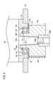
- FIG. 3 is a cross-sectional view taken along the line III-III of FIG.
- the support structure of the drive pulley 104 includes a bearing 112, a bearing holder 114, a contact plate 116, and a motor bracket 118.
- the bearing 112 is a rolling bearing that supports a radial load.
- the number of bearings 112 may be one or a plurality. When there are a plurality of bearings 112, a spacer may be provided between the bearings 112 and the bearings 112. In this embodiment, there is only one bearing 112.
- the bearing 112 has an inner ring 120, an outer ring 122, and a plurality of rolling elements 124 rotatably interposed between the inner ring 120 and the outer ring 122. Specific examples of the bearing 112 include ball bearings and the like.
- the bearing 112 is arranged between the motor 102 and the drive pulley 104.
- the bearing holder 114 supports the bearing 112 and is provided on the motor 102.
- the bearing holder 114 may be formed integrally with the motor housing of the motor 102, or may be formed separately from the motor housing of the motor 102.
- the bearing holder 114 is fixed to the motor housing of the motor 102 by fasteners such as bolts.
- the bearing holder 114 is arranged on the end face of the motor housing through which the drive shaft 102S of the motor 102 penetrates.
- the bearing holder 114 is formed with a bearing accommodating portion 126 accommodating the bearing 112 and a shaft insertion hole 128 into which the drive shaft 102S of the motor 102 is inserted.
- the bearing accommodating portion 126 is formed on the surface of the bearing holder 114 on the drive pulley 104 side, and the bearing accommodating portion 126 is recessed toward the motor 102.
- the shaft insertion hole 128 penetrates the bearing holder 114 from the bottom surface of the bearing accommodating portion 126 to the surface of the bearing holder 114 on the motor 102 side.
- the shaft insertion hole 128 has a diameter larger than the outer diameter of the inner ring 120 of the bearing 112 and smaller than the outer diameter of the outer ring 122 of the bearing 112.
- a protruding portion 104P of the drive pulley 104 is arranged in the bearing accommodating portion 126.
- the protrusion 104P projects from the surface of the drive pulley 104 facing the bearing holder 114 toward the bearing accommodating portion 126.
- the inner ring 120 of the bearing 112 housed in the bearing accommodating portion 126 is inserted through the projecting portion 104P and fitted with the projecting portion 104P. Therefore, the inner ring 120 of the bearing 112 accommodated in the bearing accommodating portion 126 rotates together with the drive pulley 104.
- the outer ring 122 of the bearing 112 accommodated in the bearing accommodating portion 126 is fitted into the gap with the bearing accommodating portion 126.
- the outer ring 122 of the bearing 112 housed in the bearing accommodating portion 126 is slidable in the axial direction of the drive shaft 102S.
- the drive shaft 102S of the motor 102 penetrates the protrusion 104P.
- the end of the protrusion 104P on the motor 102 side is arranged in the shaft insertion hole 128 of the bearing holder 114.
- An annular groove 104G is formed on the outer peripheral surface of the end portion of the protrusion 104P on the motor 102 side.
- a retaining ring 130 is fitted in the annular groove 104G.
- the retaining ring 130 is a stopper member that comes into contact with the surface of the inner ring 120 of the bearing 112 on the motor 102 side.
- the retaining ring 130 regulates the inner ring 120 from sliding toward the motor 102.
- the surface of the outer ring 122 of the bearing 112 on the motor 102 side is not in contact with the bottom surface of the bearing accommodating portion 126.
- a gap is formed between the bottom surface of the bearing accommodating portion 126 and the surface of the outer ring 122 of the bearing 112 facing the motor 102. This gap is larger than the gap between the axial peripheral surface of the outer ring 122 fitted with the gap and the axial peripheral surface of the bearing accommodating portion 126.
- the contact plate 116 regulates the inner ring 120 from sliding toward the drive pulley 104 along the axial direction, and is provided on the drive pulley 104.
- the contact plate 116 may be formed integrally with the drive pulley 104, or may be formed separately from the drive pulley 104.
- the contact plate 116 may be fixed by being sandwiched between the inner ring 120 of the bearing 112 and the drive pulley 104, and may be fixed by a fastener such as a bolt. It may be fixed to the drive pulley 104.
- the contact plate 116 has at least a portion that comes into contact with the surface of the inner ring 120 of the bearing 112 on the drive pulley 104 side.
- the contact plate 116 may be arranged inside the outer ring 122 of the bearing 112, or may extend from the outer ring 122 toward the outside in the radial direction of the drive pulley 104. When the contact plate 116 extends from the outer ring 122 of the bearing 112 toward the outside in the radial direction of the drive pulley 104, the contact plate 116 is not in contact with the surface of the outer ring 122 on the drive pulley 104 side.
- the contact plate 116 projects outward from the circumferential surface on which the belt 108 of the drive pulley 104 is hung. Further, in the present embodiment, the contact plate 116 has an inclined surface 116F that is inclined so as to be separated from the bearing 112 toward the outer side in the radial direction of the drive pulley 104. Due to the presence of the inclined surface 116F, a gap SP is formed between the contact plate 116 and the outer ring 122. As a result, the contact plate 116 is not in contact with the surface of the outer ring 122 on the drive pulley 104 side.
- the contact plate 116 is not limited to the shape of the present embodiment as long as it is not in contact with the surface of the outer ring 122 on the drive pulley 104 side.
- the motor bracket 118 is provided on the holding plate 110 so that the drive pulley 104 can slide along the direction in which the drive pulley 104 approaches or separates from the driven pulley 106 (see FIG. 2).
- the motor bracket 118 is provided with a bearing holder 114. Therefore, the bearing holder 114, the motor 102 provided with the bearing holder 114, the drive pulley 104 fixed to the drive shaft 102S of the motor 102, and the contact plate 116 provided on the drive pulley 104 are the motor bracket 118. Move together.
- the bearing holder 114 may be formed integrally with the motor bracket 118, or may be formed separately from the motor bracket 118. When the bearing holder 114 is formed separately from the motor bracket 118, the bearing holder 114 is fixed to the motor bracket 118 by fasteners such as bolts.
- the bearing 112 that supports the radial load is arranged between the motor 102 and the drive pulley 104.
- the bearing holder 114 can be provided without covering the periphery of the drive pulley 104. Therefore, the heat generated between the motor 102 or the drive pulley 104 and the belt 108 is more likely to be released to the outside than in the case of covering the periphery of the drive pulley as in Japanese Patent Application Laid-Open No. 2012-161995. Therefore, the thermal expansion of the drive pulley 104 can be suppressed.
- the inner ring 120 of the bearing 112 is fixed to the drive pulley 104 so as not to slide in the axial direction of the drive shaft 102S.
- the outer ring 122 of the bearing 112 is allowed to move in the axial direction of the drive shaft 102S between the bearing holder 114 and the drive pulley 104.
- the expansion and contraction of the drive shaft 102S in the axial direction due to the temperature change can be released together with the bearing 112 as compared with the case where the movement of the drive shaft 102S in the axial direction is not allowed.
- the drive shaft 102S in the axial direction due to a temperature change can be suppressed. Expansion and contraction can be released together with the bearing 112. Therefore, it is possible to prevent an excessive force from being applied to the drive shaft 102S of the bearing 112 or the motor 102. As a result, the load on the bearing 112 or the drive shaft 102S can be reduced.
- the present invention is not limited to this.
- the present invention can be applied to various industrial machines 10 other than injection molding machines, such as machine tools, robots, mining machines, woodworking machines, agricultural machines, construction machines and the like.
- the power transmission device 100 is provided in the industrial machine 10 as an example, but the present invention is not limited to this.
- the power transmission device 100 can be provided in any device.
- the power transmission device 100 may be provided in a vehicle or the like.
- a retaining ring 130 that fits into the annular groove 104G of the protrusion 104P of the drive pulley 104 is adopted.
- a nut 140 screwed into the thread groove 104S formed on the outer peripheral surface of the protruding portion 104P of the drive pulley 104 may be adopted as the stopper member.
- the drive shaft 102S of the motor 102 whose outer diameter becomes smaller toward the tip is adopted.
- a pulley nut is adopted as the fastener 104N.
- the drive shaft 102S of the motor 102 having a substantially constant outer diameter may be adopted.
- a bolt may be adopted as the fastener 104N.
- the recess 150 is formed on the end surface of the drive pulley 104 opposite to the motor 102 side.
- An annular outer sleeve member 152 is fitted in the recess 150.
- An annular convex portion of the inner sleeve member 154 is fitted between the drive shaft 102S inserted through the outer sleeve member 152 and the outer sleeve member 152.
- the inner sleeve member 154 and the outer sleeve member 152 are fixed by a fastener 104N (bolt).
- the outer sleeve member 152 may be integrally formed with the drive pulley 104.
- the first invention is a support structure that supports a drive pulley (104) that is fixed to a drive shaft (102S) of a motor (102) and rotates integrally with the drive shaft (102S).
- the support structure is arranged between the motor (102) and the drive pulley (104), and the bearing (112) that supports the radial load and the bearing holder (112) that is provided on the motor (102) and supports the bearing (112). 114) and.
- the inner ring (120) of the bearing (112) is fixed to the drive pulley (104) so as not to slide in the axial direction of the drive shaft (102S), and the outer ring (122) of the bearing (112) is a bearing. Axial movement between the holder (114) and the drive pulley (104) is allowed.
- the bearing holder (114) By arranging the bearing (112) that supports the radial load between the motor (102) and the drive pulley (104), the bearing holder (114) is provided without covering the periphery of the drive pulley (104). Can be done. Therefore, as compared with the case of covering the periphery of the drive pulley (104), it becomes easier to release the heat generated between the motor (102) or the drive pulley (104) and the belt (108) to the outside, and the drive pulley (104) Thermal expansion can be suppressed. Therefore, it is possible to suppress an increase in the radial load received by the drive shaft (102S) of the bearing (112) and the motor (102).
- the movement is allowed as compared with the case where the movement is not permitted.
- the expansion and contraction of the drive shaft (102S) in the axial direction due to the temperature change can be released together with the bearing (112). In this way, it is possible to suppress an excessive force from being applied to the drive shaft (102S) of the bearing (112) and the motor (102), and as a result, the drive shaft (102S) of the bearing (112) and the motor (102) The load can be reduced.
- the support structure is non-contact with the surface of the outer ring (122) of the bearing (112) on the drive pulley (104) side, and is in contact with the surface of the inner ring (120) of the bearing (112) on the drive pulley (104) side.
- a bearing plate (116) may be provided. Thereby, the contact plate (116) is used to regulate the axial movement of the inner ring (120) of the bearing (112) and allow the outer ring (122) of the bearing (112) to move in the axial direction. Can be done.
- the contact plate (116) may have an inclined surface (116F) that is inclined so as to be separated from the bearing (112) toward the outer side in the radial direction of the drive pulley (104). Thereby, the inclination angle of the inclined surface (116F) can be changed according to the type of the motor (102), the bearing (112), and the like. Therefore, it is possible to appropriately set the gap (SP) between the surface of the outer ring (122) on the drive pulley (104) side and the contact plate (116) without forming it into a complicated shape. ..
- the contact plate (116) may protrude outward from the circumferential surface on which the belt (108) of the drive pulley (104) is hung. As a result, it is possible to prevent the belt (108) from coming off from the drive pulley (104) while allowing the outer ring (122) of the bearing (112) to move in the axial direction.
- the contact plate (116) may be integrally formed with the drive pulley (104). As a result, the number of parts can be reduced as compared with the case where the contact plate (116) is separate from the drive pulley (104).
- the surface of the bearing holder (114) on the drive pulley (104) side is recessed on the motor (102) side to form a bearing accommodating portion (126) for accommodating the bearing (112), and the outer ring (122) of the bearing (112) is formed. ) May be fitted to the bearing accommodating portion (126) in a non-contact state with the bottom surface of the bearing accommodating portion (126). Thereby, it is possible to allow the outer ring (122) of the bearing (112) to move in the axial direction while supporting the radial load.
- the drive pulley (104) has a protrusion (104P) that protrudes toward the bearing accommodating portion (126), and the inner ring (120) of the bearing (112) is inserted through the protrusion (104P) and the protrusion (104P). 104P) may be fitted. As a result, it is possible to prevent the inner ring (120) from shifting.
- the support structure may include a stopper member that comes into contact with the surface of the inner ring (120) of the bearing (112) on the motor (102) side. As a result, it is possible to prevent the inner ring (120) from shifting.
- a drive shaft (102S) is inserted on the bottom surface side of the bearing accommodating portion (126), and a shaft insertion hole (128) having a diameter larger than the outer diameter of the inner ring (120) of the bearing (112) is formed to form a stopper member.
- a drive shaft (102S) is inserted on the bottom surface side of the bearing accommodating portion (126), and a shaft insertion hole (128) having a diameter larger than the outer diameter of the inner ring (120) of the bearing (112) is formed to form a stopper member.
- the depth of the bearing accommodating portion (126) can be adjusted according to the type of the bearing (112).
- the support structure is a motor bracket (118) provided so as to be slidable along the direction in which the drive pulley (104) approaches or separates from the driven pulley (106) on which the belt (108) is hung together with the drive pulley (104). ), And the bearing holder (114) may be provided on the motor bracket (118) and may be movable together with the motor bracket (118). Thereby, the tension of the belt (108) can be adjusted, and as a result, the radial load can be appropriately applied to the bearing (112).
- the bearing holder (114) may be integrally formed with the motor bracket (118). As a result, the number of parts can be reduced as compared with the case where the bearing holder (114) is separate from the motor bracket (118).
- the second invention is an industrial machine (10) including the above-mentioned support structure, a motor (102), and a drive pulley (104). Since the industrial machine (10) includes the above-mentioned support structure and the motor (102), it is possible to suppress an excessive force from being applied to the bearing (112) and the drive shaft (102S) of the motor (102). As a result, the load on the drive shaft (102S) of the bearing (112) and the motor (102) can be reduced.
Landscapes
- Engineering & Computer Science (AREA)
- General Engineering & Computer Science (AREA)
- Mechanical Engineering (AREA)
- Manufacturing & Machinery (AREA)
- Devices For Conveying Motion By Means Of Endless Flexible Members (AREA)
- Mounting Of Bearings Or Others (AREA)
- Rolling Contact Bearings (AREA)
- Injection Moulding Of Plastics Or The Like (AREA)
- Support Of The Bearing (AREA)
- Pulleys (AREA)
Abstract
モータの駆動軸や軸受の負荷を低減し得る支持構造および産業機械を提供する。一実施形態の支持構造は、モータ(102)と駆動プーリ(104)との間に配置される軸受(112)と、モータ(102)に設けられる軸受ホルダ(114)と、を備える。軸受(112)の内輪(120)は、駆動プーリ(104)に対して駆動軸(102S)の軸方向にスライド不能となるように固定され、軸受(112)の外輪(122)は、軸受ホルダ(114)と駆動プーリ(104)との間における軸方向の移動が許容される。
Description
本発明は、モータの駆動軸と一体に回転する駆動プーリを支持する支持構造、および、その支持機構を有する産業機械に関する。
特開2012-161995号公報には、モータブラケットに固定されたモータと、モータの駆動軸に連結された駆動プーリと、保持プレートに固定された従動プーリと、駆動プーリと従動プーリとに架けられたベルトとを有する動力伝達装置が開示されている。
特開2012-161995号公報の動力伝達装置では、モータの駆動軸が、モータブラケットを貫通して延びている。モータの駆動軸の先端部分には、駆動プーリを回転可能に支持する軸受が設けられる。この軸受を支持する軸受ホルダが、駆動プーリの周囲を覆うようにモータブラケットに取り付けられている。
しかしながら、特開2012-161995号公報の動力伝達装置では、駆動プーリの周囲が軸受ホルダで覆われているため、モータ或いは駆動プーリと、ベルトとの間で生じる熱が外部に放出され難い。したがって、駆動プーリが熱膨張し易い。駆動プーリが熱膨張すると、軸受やモータの駆動軸が受けるラジアル荷重が増加し、モータや軸受が短命化する傾向にある。
そこで、本発明は、軸受やモータの駆動軸の負荷を低減し得る支持構造および産業機械を提供する。
本発明の第1の態様は、
モータの駆動軸に取り付けられ、前記駆動軸と一体に回転する駆動プーリを支持する支持構造であって、
前記モータと前記駆動プーリとの間に配置され、ラジアル荷重を支持する軸受と、
前記モータに設けられ、前記軸受を支持する軸受ホルダと、
を備え、
前記軸受の内輪は、前記駆動プーリに対して前記駆動軸の軸方向にスライド不能となるように固定され、
前記軸受の外輪は、前記軸受ホルダと前記駆動プーリとの間における前記軸方向の移動が許容される。
モータの駆動軸に取り付けられ、前記駆動軸と一体に回転する駆動プーリを支持する支持構造であって、
前記モータと前記駆動プーリとの間に配置され、ラジアル荷重を支持する軸受と、
前記モータに設けられ、前記軸受を支持する軸受ホルダと、
を備え、
前記軸受の内輪は、前記駆動プーリに対して前記駆動軸の軸方向にスライド不能となるように固定され、
前記軸受の外輪は、前記軸受ホルダと前記駆動プーリとの間における前記軸方向の移動が許容される。
本発明の第2の態様は、
上記の支持構造と、モータと、駆動プーリとを備える産業機械である。
上記の支持構造と、モータと、駆動プーリとを備える産業機械である。
本発明の態様によれば、軸受やモータの駆動軸の負荷を低減することができる。
すなわち、ラジアル荷重を支持する軸受が、モータと駆動プーリとの間に配置されることで、駆動プーリの周囲を覆うことなく軸受ホルダを設けることができる。したがって、駆動プーリの周囲を覆う場合に比べて、モータや駆動プーリとベルトの間で生じる熱を外部に放出し易くなり、駆動プーリの熱膨張を抑制することができる。このため、軸受やモータの駆動軸が受けるラジアル荷重の増加を抑制することができる。
また、軸受ホルダと駆動プーリとの間における軸受の外輪の軸方向の移動が許容されているため、当該移動が許容されていない場合に比べて、温度変化による軸方向へのモータの駆動軸の伸縮を軸受とともに逃がすことができる。
こうして、軸受やモータの駆動軸に過大な力がかかることを抑制することができ、この結果、軸受やモータの駆動軸の負荷を低減することができる。
すなわち、ラジアル荷重を支持する軸受が、モータと駆動プーリとの間に配置されることで、駆動プーリの周囲を覆うことなく軸受ホルダを設けることができる。したがって、駆動プーリの周囲を覆う場合に比べて、モータや駆動プーリとベルトの間で生じる熱を外部に放出し易くなり、駆動プーリの熱膨張を抑制することができる。このため、軸受やモータの駆動軸が受けるラジアル荷重の増加を抑制することができる。
また、軸受ホルダと駆動プーリとの間における軸受の外輪の軸方向の移動が許容されているため、当該移動が許容されていない場合に比べて、温度変化による軸方向へのモータの駆動軸の伸縮を軸受とともに逃がすことができる。
こうして、軸受やモータの駆動軸に過大な力がかかることを抑制することができ、この結果、軸受やモータの駆動軸の負荷を低減することができる。
本発明について、好適な実施形態を挙げ、添付の図面を参照して以下に詳細に説明する。
[実施形態]
図1は、一実施形態による産業機械10を示す概略図である。ここでは、産業機械10が射出成形機である場合を例に説明するが、これに限定されるものではない。
図1は、一実施形態による産業機械10を示す概略図である。ここでは、産業機械10が射出成形機である場合を例に説明するが、これに限定されるものではない。
産業機械10には、型締装置12と、射出装置14とが備えられている。型締装置12と射出装置14とは、ベース16上に設置されている。産業機械10には、型締装置12と射出装置14とを制御する制御部(制御装置)18が更に備えられている。
型締装置12には、リアプラテン22と、可動プラテン24と、固定プラテン26とが備えられている。可動プラテン24は、リアプラテン22と固定プラテン26との間に設けられたタイバー28に沿って進退可能である。
可動プラテン24と固定プラテン26との間には、金型30が備えられている。金型30には、可動金型32と固定金型34とが備えられている。可動金型32は、可動プラテン24に取り付けられている。固定金型34は、固定プラテン26に取り付けられている。
リアプラテン22と可動プラテン24との間には、トグルリンク36が備えられている。トグルリンク36は、クロスリンク38を介してクロスヘッド40に接続されている。
型締装置12には、型開閉機構42が更に備えられている。型開閉機構42は、可動プラテン24を固定プラテン26に対して進退させ得る。型開閉機構42には、動力伝達装置100Aが備えられている。動力伝達装置100Aには、モータ(型開閉モータ)102Aと、駆動プーリ104Aと、従動プーリ106Aと、ベルト108Aとが備えられている。動力伝達装置一般について説明する際には、符号100を用い、個々の動力伝達装置について説明する際には、符号100A~100Dを用いる。モータ一般について説明する際には、符号102を用い、個々のモータについて説明する際には、符号102A~102Dを用いる。駆動プーリ一般について説明する際には、符号104を用い、個々の駆動プーリについて説明する際には、符号104A~104Dを用いる。従動プーリ一般について説明する際には、符号106を用い、個々の従動プーリについて説明する際には、符号106A~106Dを用いる。ベルト一般について説明する際には、符号108を用い、個々のベルトについて説明する際には、符号108A~108Dを用いる。
モータ102Aの駆動軸には駆動プーリ104Aが固定される。駆動プーリ104Aは、モータ102Aと一緒に回転する。駆動プーリ104Aと従動プーリ106Aとには、ベルト108Aが架けられている。従動プーリ106Aは、ベルト108Aにより伝達される駆動プーリ104Aの回転力に基づいて回転する。モータ102Aの駆動は、制御部18によって制御され得る。
モータ102Aの回転運動は、クロスヘッド40に接続されているボールねじ機構46に伝達される。モータ102Aから伝達された回転運動は、ボールねじ機構46によってクロスヘッド40の進退方向の運動に変換される。クロスヘッド40の進退方向の運動は、トグルリンク36を介して可動プラテン24に伝達される。こうして、可動プラテン24が固定プラテン26に対して進退され得る。
型締装置12には、エジェクタ機構48が備えられている。エジェクタ機構48は、可動金型32から成形品を取り出すためのものである。エジェクタ機構48には、動力伝達装置100Bが備えられている。動力伝達装置100Bには、モータ(エジェクタモータ)102Bと、駆動プーリ104Bと、従動プーリ106Bと、ベルト108Bとが備えられている。
モータ102Bの駆動軸には駆動プーリ104Bが固定される。駆動プーリ104Bは、モータ102Bと一緒に回転する。駆動プーリ104Bと従動プーリ106Bとには、ベルト108Bが架けられている。従動プーリ106Bは、ベルト108Bにより伝達される駆動プーリ104Bの回転力に基づいて回転する。モータ102Bの駆動は、制御部18によって制御され得る。
モータ102Bの回転運動は、エジェクタピン52に接続されているボールねじ機構54に伝達される。モータ102Bから伝達された回転運動は、ボールねじ機構54によって、エジェクタピン52の進退方向の運動に変換される。こうして、エジェクタピン52が可動プラテン24に対して進退され得る。エジェクタピン52が可動プラテン24側に移動されることにより、可動金型32から成形品が押し出され、成形品が取り出される。
射出装置14には、ノズル56と、シリンダ58と、スクリュ60と、ホッパ62と、ヒータ64とが備えられている。ノズル56は、シリンダ58の先端に備えられている。シリンダ58は、中空の部材によって構成されている。シリンダ58内には、スクリュ60が挿通されている。シリンダ58と、スクリュ60とは、金型30の開閉方向に延びている。シリンダ58には、ホッパ62が接続されている。ホッパ62は、シリンダ58内に樹脂材料を投入するためのものである。ホッパ62から投入された樹脂材料がペレット状の場合は、ヒータ64によって樹脂材料が溶融される。
射出装置14には、樹脂供給機構66と、射出機構68とが備えられている。樹脂供給機構66は、シリンダ58内の樹脂材料をシリンダ58のノズル56に向けて送る。射出機構68は、樹脂材料を金型30に向けて射出する。樹脂供給機構66には、動力伝達装置100Cが備えられている。動力伝達装置100Cには、モータ(回転運動用モータ)102Cと、駆動プーリ104Cと、従動プーリ106Cと、ベルト108Cとが備えられている。
モータ102Cの駆動軸には駆動プーリ104Cが固定される。駆動プーリ104Cは、モータ102Cと一緒に回転する。駆動プーリ104Cと、従動プーリ106Cとにはベルト108Cが架けられている。従動プーリ106Cは、ベルト108Cにより伝達される駆動プーリ104Cの回転力に基づいて回転する。モータ102Cの駆動は、制御部18によって制御され得る。
モータ102Cの回転運動は、スクリュ60に接続されたブッシュ72に伝達され、これにより、スクリュ60が軸回りに回転する。スクリュ60が軸回りに回転すると、シリンダ58内の樹脂材料がシリンダ58のノズル56に向けて送られる。
射出機構68には、動力伝達装置100Dが備えられている。動力伝達装置100Dには、モータ(直線運動用モータ)102Dと、駆動プーリ104Dと、従動プーリ106Dと、ベルト108Dとが備えられている。
モータ102Dの駆動軸には駆動プーリ104Dが固定される。駆動プーリ104Dは、モータ102Dと一緒に回転する。駆動プーリ104Dと、従動プーリ106Dとにはベルト108Dが架けられている。従動プーリ106Dは、ベルト108Dにより伝達される駆動プーリ104Dの回転力に基づいて回転する。モータ102Dの駆動は、制御部18によって制御され得る。
モータ102Dの回転運動は、ボールねじ機構78によってブッシュ72の進退方向の運動に変換され、スクリュ60に伝達される。これにより、スクリュ60が軸方向に移動する。スクリュ60がノズル56に向かう方向に移動することにより、シリンダ58内の樹脂材料がノズル56から金型30に向けて射出される。
以下は、動力伝達装置100一般の駆動プーリ104の支持構造に関して説明する。図2は、一実施形態による動力伝達装置100を示す概略図である。図2に示すように、動力伝達装置100には、モータ102、駆動プーリ104、従動プーリ106およびベルト108が備えられている。
モータ102は、保持プレート110に設けられる。モータ102は、保持プレート110に対して移動可能に設けられてもよい。本実施形態では、モータ102は、保持プレート110に対して移動可能に設けられている。モータ102の駆動軸102Sには駆動プーリ104が固定される。駆動プーリ104は、締結具104Nにより駆動軸102Sに固定される。このため、駆動プーリ104は、モータ102と一緒に回転する。図2では、締結具104Nとしてプーリナットの場合が例示される。駆動プーリ104は、ワッシャ104W(図3参照)を介して締結具104N(プーリナット)により駆動軸102Sに固定されている。従動プーリ106は、保持プレート110に固定される。ベルト108は、駆動プーリ104と従動プーリ106とに架けられる。従動プーリ106は、ベルト108により伝達される駆動プーリ104の回転力に基づいて回転する。
駆動プーリ104の直径は、従動プーリ106の直径より小さくてもよく、従動プーリ106の直径より大きくてもよく、従動プーリ106の直径と同じであってもよい。駆動プーリ104と従動プーリ106とに架けられるベルト108の本数は、1本であってもよく、複数本であってもよい。図2では、駆動プーリ104の直径が従動プーリ106の直径より小さく、駆動プーリ104と従動プーリ106とに架けられるベルト108の本数が1本である場合が例示されている。なお、ベルト108には、ベルト108の延伸方向に間隔をあけて複数の歯が設けられていてもよく、当該歯が設けられていなくてもよい。
図3は、図2のIII-III矢視断面図である。図3に示すように、駆動プーリ104の支持構造は、軸受112と、軸受ホルダ114と、当接板116と、モータブラケット118と、を有する。
軸受112は、ラジアル荷重を支持する転がり軸受である。軸受112は、1つであってもよく、複数であってもよい。軸受112が複数である場合、軸受112と軸受112との間に間座が設けられてもよい。本実施形態では、軸受112は1つである。軸受112は、内輪120と、外輪122と、内輪120と外輪122との間に転動可能に介装される複数の転動体124とを有する。軸受112の具体例として、玉軸受等が挙げられる。軸受112は、モータ102と駆動プーリ104との間に配置される。
軸受ホルダ114は、軸受112を支持するものであり、モータ102に設けられる。軸受ホルダ114は、モータ102のモータハウジングと一体に形成されてもよく、モータ102のモータハウジングとは別体に形成されてもよい。軸受ホルダ114がモータハウジングと別体に形成される場合、軸受ホルダ114は、ボルト等の締結具によりモータ102のモータハウジングに固定される。軸受ホルダ114は、モータ102の駆動軸102Sが貫通するモータハウジングの端面に配置される。
軸受ホルダ114には、軸受112を収容する軸受収容部126と、モータ102の駆動軸102Sが挿通される軸挿通孔128とが形成される。軸受収容部126は、軸受ホルダ114の駆動プーリ104側の面に形成され、軸受収容部126は、モータ102に向かって凹んでいる。軸挿通孔128は、軸受収容部126の底面から、軸受ホルダ114のモータ102側の面までにわたって軸受ホルダ114を貫通する。軸挿通孔128は、軸受112の内輪120の外径よりも大きく、かつ、軸受112の外輪122の外径よりも小さい径を有する。
軸受収容部126には、駆動プーリ104の突出部104Pが配置される。突出部104Pは、軸受ホルダ114に向く駆動プーリ104の面から軸受収容部126に向かって突出する。軸受収容部126に収容される軸受112の内輪120は、突出部104Pに挿通されて突出部104Pと嵌合する。このため、軸受収容部126に収容される軸受112の内輪120は、駆動プーリ104と一緒に回転する。軸受収容部126に収容される軸受112の外輪122は、軸受収容部126とすき間嵌めされる。軸受収容部126に収容される軸受112の外輪122は、駆動軸102Sの軸方向にスライド可能である。
突出部104Pにはモータ102の駆動軸102Sが貫通する。突出部104Pのモータ102側の端部は、軸受ホルダ114の軸挿通孔128に配置される。突出部104Pのモータ102側の端部の外周面には、環状溝104Gが形成される。環状溝104Gには、止め輪130が嵌っている。
止め輪130は、軸受112の内輪120のモータ102側の面と当接するストッパー部材である。止め輪130は、モータ102に向かって内輪120がスライドしないように規制している。なお、軸受112の外輪122のモータ102側の面は、軸受収容部126の底面と非接触である。軸受収容部126の底面と、モータ102に向く軸受112の外輪122の面との間には隙間が形成される。この隙間は、すき間嵌めされた外輪122の軸回り面と軸受収容部126の軸回り面との間の隙間よりも大きい。
当接板116は、軸方向に沿って駆動プーリ104側に内輪120がスライドしないように規制するものであり、駆動プーリ104に設けられる。当接板116は、駆動プーリ104と一体に形成されてもよく、駆動プーリ104とは別体に形成されてもよい。当接板116が駆動プーリ104と別体に形成される場合、当接板116は、軸受112の内輪120と駆動プーリ104とに挟まれることで固定されてもよく、ボルト等の締結具により駆動プーリ104に固定されてもよい。
当接板116は、少なくとも、軸受112の内輪120の駆動プーリ104側の面と当接する部位を有する。なお、当接板116は、軸受112の外輪122の内側に配置されてもよく、外輪122から駆動プーリ104の径方向の外側に向かって延びていてもよい。軸受112の外輪122から駆動プーリ104の径方向の外側に向かって当接板116が延びている場合、当接板116は、当該外輪122の駆動プーリ104側の面と非接触である。
本実施形態では、当接板116は、駆動プーリ104のベルト108が架けられる円周面よりも外側に突出する。また、本実施形態では、当接板116は、駆動プーリ104の径方向の外側に向かうほど軸受112から離間するように傾斜する傾斜面116Fを有する。この傾斜面116Fがあることで、当接板116と外輪122との間に隙間SPが形成される。これにより、当接板116が、外輪122の駆動プーリ104側の面と非接触となる。なお、当接板116は、外輪122の駆動プーリ104側の面と非接触である限り、本実施形態の形状に限定されない。
モータブラケット118は、従動プーリ106に対して駆動プーリ104が接近または隔離する方向に沿ってスライドできるように、保持プレート110に設けられている(図2参照)。このモータブラケット118には、軸受ホルダ114が設けられる。したがって、軸受ホルダ114と、当該軸受ホルダ114が設けられるモータ102と、モータ102の駆動軸102Sに固定される駆動プーリ104と、駆動プーリ104に設けられる当接板116とは、モータブラケット118と一緒に移動する。
なお、軸受ホルダ114は、モータブラケット118と一体に形成されていてもよいし、モータブラケット118とは別体に形成されてもよい。軸受ホルダ114がモータブラケット118と別体に形成される場合、軸受ホルダ114は、ボルト等の締結具によりモータブラケット118に固定される。
以上説明したように、本実施形態による駆動プーリ104の支持構造では、ラジアル荷重を支持する軸受112が、モータ102と駆動プーリ104との間に配置されている。これにより、駆動プーリ104の周囲を覆うことなく軸受ホルダ114を設けることができる。このため、特開2012-161995号公報のように駆動プーリの周囲を覆う場合に比べて、モータ102や駆動プーリ104とベルト108の間で生じる熱を外部に放出し易くなる。したがって、駆動プーリ104の熱膨張を抑制することができる。その結果、軸受112やモータ102の駆動軸102Sが受けるラジアル荷重の増加を抑制することができる。また、特開2012-161995号公報のように駆動プーリの周囲を覆う場合に比べて省スペース化を図ることができるとともに、ベルト108の交換やメンテナンスを容易に実行することができる。
また、本実施形態による駆動プーリ104の支持構造では、軸受112の内輪120は、駆動プーリ104に対して駆動軸102Sの軸方向にスライド不能となるように固定される。一方、軸受112の外輪122は、軸受ホルダ114と駆動プーリ104との間における駆動軸102Sの軸方向の移動が許容される。これにより、駆動軸102Sの軸方向の移動が許容されていない場合に比べて、温度変化による駆動軸102Sの軸方向への伸縮を軸受112とともに逃がすことができる。
このように駆動プーリ104の支持構造によれば、駆動プーリ104の熱膨張に起因する軸受112のラジアル荷重の増加を抑制することができることに加えて、温度変化による軸方向への駆動軸102Sの伸縮を軸受112とともに逃がすことができる。したがって、軸受112或いはモータ102の駆動軸102Sに過大な力がかかることを防ぐことができる。その結果、軸受112或いは駆動軸102Sの負荷を低減することができる。
[変形例]
本発明についての好適な実施形態を上述したが、本発明は上記実施形態に限定されるものではなく、本発明の要旨を逸脱しない範囲において、種々の改変が可能である。
本発明についての好適な実施形態を上述したが、本発明は上記実施形態に限定されるものではなく、本発明の要旨を逸脱しない範囲において、種々の改変が可能である。
例えば、上記実施形態では、産業機械10が、射出成形機である場合を例に説明したが、これに限定されるものではない。射出成形機以外の様々な産業機械10、例えば、工作機械、ロボット、鉱山機械、木工機械、農業機械、建設機械等に本発明を適用することができる。
また、上記実施形態では、動力伝達装置100が産業機械10に備える場合を例に説明したが、これに限定されるものではない。動力伝達装置100は、あらゆる装置に備えられ得る。例えば、動力伝達装置100が、車両等に備えられるようにしてもよい。
また、上記実施形態では、軸受112の内輪120のモータ102側の面と当接するストッパー部材として、駆動プーリ104の突出部104Pの環状溝104Gに嵌まる止め輪130が採用されたが、これに限定されるものではない。例えば、図4に示すように、駆動プーリ104の突出部104Pの外周面に形成されるねじ溝104Sに螺合するナット140が、ストッパー部材として採用されてもよい。
また、上記実施形態では、先端に向かうほど外径が小さくなるモータ102の駆動軸102Sが採用された。また、上記実施形態では、締結具104Nとして、プーリナットが採用された。例えば、図5に示すように、外径が略一定であるモータ102の駆動軸102Sが採用されてもよい。また、締結具104Nとして、ボルトが採用されてもよい。図5の例示では、駆動プーリ104のモータ102側とは逆側の端面に凹部150が形成される。この凹部150には環状のアウタースリーブ部材152が嵌合される。アウタースリーブ部材152に挿通される駆動軸102Sと、アウタースリーブ部材152との間にはインナースリーブ部材154の環状凸部が嵌め込まれる。インナースリーブ部材154と、アウタースリーブ部材152とは、締結具104N(ボルト)により固定される。なお、アウタースリーブ部材152は、駆動プーリ104と一体に形成されていてもよい。
以上をまとめると以下のようになる。
第1の発明は、モータ(102)の駆動軸(102S)に固定され、駆動軸(102S)と一体に回転する駆動プーリ(104)を支持する支持構造である。支持構造は、モータ(102)と駆動プーリ(104)との間に配置され、ラジアル荷重を支持する軸受(112)と、モータ(102)に設けられ、軸受(112)を支持する軸受ホルダ(114)と、を備える。軸受(112)の内輪(120)は、駆動プーリ(104)に対して前記駆動軸(102S)の軸方向にスライド不能となるように固定され、軸受(112)の外輪(122)は、軸受ホルダ(114)と駆動プーリ(104)との間における軸方向の移動が許容される。
ラジアル荷重を支持する軸受(112)が、モータ(102)と駆動プーリ(104)との間に配置されることで、駆動プーリ(104)の周囲を覆うことなく軸受ホルダ(114)を設けることができる。したがって、駆動プーリ(104)の周囲を覆う場合に比べて、モータ(102)や駆動プーリ(104)とベルト(108)の間で生じる熱を外部に放出し易くなり、駆動プーリ(104)の熱膨張を抑制することができる。このため、軸受(112)やモータ(102)の駆動軸(102S)が受けるラジアル荷重の増加を抑制することができる。また、軸受ホルダ(114)と駆動プーリ(104)との間における軸受(112)の外輪(122)の軸方向の移動が許容されているため、当該移動が許容されていない場合に比べて、温度変化による軸方向への駆動軸(102S)の伸縮を軸受(112)とともに逃がすことができる。こうして、軸受(112)やモータ(102)の駆動軸(102S)に過大な力がかかることを抑制することができ、この結果、軸受(112)やモータ(102)の駆動軸(102S)の負荷を低減することができる。
支持構造は、軸受(112)の外輪(122)の駆動プーリ(104)側の面と非接触であり、軸受(112)の内輪(120)の駆動プーリ(104)側の面と当接する当接板(116)を備えてもよい。これにより、当接板(116)を用いて、軸受(112)の内輪(120)の軸方向の移動を規制するとともに、軸受(112)の外輪(122)の軸方向の移動を許容することができる。
当接板(116)は、駆動プーリ(104)の径方向の外側に向かうほど軸受(112)から離間するように傾斜する傾斜面(116F)を有してもよい。これにより、モータ(102)や軸受(112)の種類等に応じて、傾斜面(116F)の傾斜角度を変えることができる。したがって、複雑な形状に形成しなくても、外輪(122)の駆動プーリ(104)側の面と当接板(116)との間の隙間(SP)を適切に設定することが可能となる。
当接板(116)は、駆動プーリ(104)のベルト(108)が架けられる円周面よりも外側に突出していてもよい。これにより、軸受(112)の外輪(122)の軸方向の移動を許容させつつ、駆動プーリ(104)からベルト(108)が外れることを抑制することができる。
当接板(116)は、駆動プーリ(104)と一体に形成されてもよい。これにより、当接板(116)が駆動プーリ(104)と別体である場合に比べて、部品点数を削減することができる。
軸受ホルダ(114)の駆動プーリ(104)側の面には、モータ(102)側に凹み、軸受(112)を収容する軸受収容部(126)が形成され、軸受(112)の外輪(122)は、軸受収容部(126)の底面と非接触の状態で軸受収容部(126)と嵌合してもよい。これにより、ラジアル荷重を支持しながら、軸受(112)の外輪(122)の軸方向の移動を許容することができる。
駆動プーリ(104)は、軸受収容部(126)に向けて突出する突出部(104P)を有し、軸受(112)の内輪(120)は、突出部(104P)に挿通されて突出部(104P)と嵌合してもよい。これにより、内輪(120)がずれることを抑制することができる。
支持構造は、軸受(112)の内輪(120)のモータ(102)側の面と当接するストッパー部材を備えてもよい。これにより、内輪(120)がずれることを抑制することができる。
軸受収容部(126)の底面側には、駆動軸(102S)が挿通され、軸受(112)の内輪(120)の外径よりも大きい径の軸挿通孔(128)が形成され、ストッパー部材は、突出部(104P)の外周面に形成された環状溝(104G)に嵌まる止め輪(130)であってもよい。これにより、内輪(120)がずれることを抑制することができる。
軸受収容部(126)の底面側には、駆動軸(102S)が挿通され、軸受(112)の内輪(120)の外径よりも大きい径の軸挿通孔(128)が形成され、ストッパー部材は、突出部(104P)の外周面に形成されたねじ溝(104S)に螺合するナット(140)であってもよい。これにより、内輪(120)がずれることを抑制することができる。また、軸受(112)の種類に応じて、軸受収容部(126)の深さを調整することができる。
支持構造は、駆動プーリ(104)と一緒にベルト(108)が架けられる従動プーリ(106)に対して駆動プーリ(104)が接近または隔離する方向に沿ってスライド可能に設けられるモータブラケット(118)を備え、軸受ホルダ(114)は、モータブラケット(118)に設けられ、モータブラケット(118)と一緒に可動してもよい。これにより、ベルト(108)の張力を調整することができ、この結果、軸受(112)に対してラジアル荷重を適切に与えることができる。
軸受ホルダ(114)は、モータブラケット(118)と一体に形成されてもよい。これにより、軸受ホルダ(114)がモータブラケット(118)と別体である場合に比べて、部品点数を削減することができる。
第2の発明は、上記の支持構造と、モータ(102)と、駆動プーリ(104)とを備える産業機械(10)である。産業機械(10)は、上記の支持構造と、モータ(102)を備えているため、軸受(112)やモータ(102)の駆動軸(102S)に過大な力がかかることを抑制することができ、この結果、軸受(112)やモータ(102)の駆動軸(102S)の負荷を低減することができる。
Claims (13)
- モータ(102)の駆動軸(102S)に固定され、前記駆動軸と一体に回転する駆動プーリ(104)を支持する支持構造であって、
前記モータと前記駆動プーリとの間に配置され、ラジアル荷重を支持する軸受(112)と、
前記モータに設けられ、前記軸受を支持する軸受ホルダ(114)と、
を備え、
前記軸受の内輪(120)は、前記駆動プーリに対して前記駆動軸の軸方向にスライド不能となるように固定され、
前記軸受の外輪(122)は、前記軸受ホルダと前記駆動プーリとの間における前記軸方向の移動が許容される、支持構造。 - 請求項1に記載の支持構造であって、
前記軸受の外輪の前記駆動プーリ側の面と非接触であり、前記軸受の内輪の前記駆動プーリ側の面と当接する当接板(116)を備える、支持構造。 - 請求項2に記載の支持構造であって、
前記当接板は、前記駆動プーリの径方向の外側に向かうほど前記軸受から離間するように傾斜する傾斜面(116F)を有する、支持構造。 - 請求項2または3に記載の支持構造であって、
前記当接板は、前記駆動プーリのベルト(108)が架けられる円周面よりも外側に突出している、支持構造。 - 請求項2~4のいずれか1項に記載の支持構造であって、
前記当接板は、前記駆動プーリと一体に形成される、支持構造。 - 請求項1~5のいずれか1項に記載の支持構造であって、
前記軸受ホルダの前記駆動プーリ側の面には、前記モータ側に凹み、前記軸受を収容する軸受収容部(126)が形成され、
前記軸受の外輪は、前記軸受収容部の底面と非接触の状態で前記軸受収容部と嵌合する、支持構造。 - 請求項6に記載の支持構造であって、
前記駆動プーリは、前記軸受収容部に向けて突出する突出部(104P)を有し、
前記軸受の内輪は、前記突出部に挿通されて前記突出部と嵌合する、支持構造。 - 請求項7に記載の支持構造であって、
前記軸受の内輪の前記モータ側の面と当接するストッパー部材を備える、支持構造。 - 請求項8に記載の支持構造であって、
前記軸受収容部の底面側には、前記駆動軸が挿通され、前記軸受の内輪の外径よりも大きい径の軸挿通孔(128)が形成され、
前記ストッパー部材は、前記突出部の外周面に形成された環状溝(104G)に嵌まる止め輪(130)である、支持構造。 - 請求項8に記載の支持構造であって、
前記軸受収容部の底面側には、前記駆動軸が挿通され、前記軸受の内輪の外径よりも大きい径の軸挿通孔(128)が形成され、
前記ストッパー部材は、前記突出部の外周面に形成されたねじ溝(104S)に螺合するナット(140)である、支持構造。 - 請求項1~10のいずれか1項に記載の支持構造であって、
前記駆動プーリと一緒にベルトが架けられる従動プーリ(106)に対して前記駆動プーリが接近または隔離する方向に沿ってスライド可能に設けられるモータブラケット(118)
を備え、
前記軸受ホルダは、前記モータブラケットに設けられ、前記モータブラケットと一緒に可動する、支持構造。 - 請求項11に記載の支持構造であって、
前記軸受ホルダは、前記モータブラケットと一体に形成される、支持構造。 - 請求項1~12のいずれか1項に記載の支持構造と、前記モータと、前記駆動プーリとを備える産業機械(10)。
Priority Applications (4)
| Application Number | Priority Date | Filing Date | Title |
|---|---|---|---|
| DE112021003967.9T DE112021003967T5 (de) | 2020-07-27 | 2021-07-21 | Trägerstruktur und Industriemaschine |
| US18/006,793 US20230265889A1 (en) | 2020-07-27 | 2021-07-21 | Support structure and industrial machine |
| JP2022540234A JP7502447B2 (ja) | 2020-07-27 | 2021-07-21 | 支持構造および産業機械 |
| CN202180059619.8A CN116157245A (zh) | 2020-07-27 | 2021-07-21 | 支承结构及产业用机械 |
Applications Claiming Priority (2)
| Application Number | Priority Date | Filing Date | Title |
|---|---|---|---|
| JP2020126089 | 2020-07-27 | ||
| JP2020-126089 | 2020-07-27 |
Publications (1)
| Publication Number | Publication Date |
|---|---|
| WO2022024901A1 true WO2022024901A1 (ja) | 2022-02-03 |
Family
ID=80036877
Family Applications (1)
| Application Number | Title | Priority Date | Filing Date |
|---|---|---|---|
| PCT/JP2021/027258 Ceased WO2022024901A1 (ja) | 2020-07-27 | 2021-07-21 | 支持構造および産業機械 |
Country Status (5)
| Country | Link |
|---|---|
| US (1) | US20230265889A1 (ja) |
| JP (1) | JP7502447B2 (ja) |
| CN (1) | CN116157245A (ja) |
| DE (1) | DE112021003967T5 (ja) |
| WO (1) | WO2022024901A1 (ja) |
Citations (6)
| Publication number | Priority date | Publication date | Assignee | Title |
|---|---|---|---|---|
| US4529324A (en) * | 1980-10-24 | 1985-07-16 | Sperry Corporation | Spindle bearing follower |
| JPH0890306A (ja) * | 1994-09-21 | 1996-04-09 | Enshu Ltd | 工作機械の主軸装置 |
| JPH11332201A (ja) * | 1998-05-14 | 1999-11-30 | Nippon Densan Corp | スピンドルモータ |
| JP2003120791A (ja) * | 2001-10-10 | 2003-04-23 | Nsk Ltd | プーリの回転支持装置 |
| JP2012161995A (ja) * | 2011-02-07 | 2012-08-30 | Fanuc Ltd | 静音性を有する射出成形機 |
| JP2013237400A (ja) * | 2012-05-16 | 2013-11-28 | Jtekt Corp | 電動パワーステアリング装置 |
Family Cites Families (14)
| Publication number | Priority date | Publication date | Assignee | Title |
|---|---|---|---|---|
| US1437833A (en) * | 1919-01-24 | 1922-12-05 | Timken Roller Bearing Co | Antifriction bearing |
| US3287988A (en) * | 1964-05-11 | 1966-11-29 | Heyer Don | Variable speed pulley-belt drive |
| US5156573A (en) * | 1991-06-05 | 1992-10-20 | Litens Automotive Partnership | Serpentine drive with coil spring-one-way clutch alternator connection |
| US5707157A (en) * | 1996-08-07 | 1998-01-13 | New Venture Gear, Inc. | Bearing retention mechanism |
| DE19921750B4 (de) * | 1998-05-18 | 2012-03-08 | Schaeffler Technologies Gmbh & Co. Kg | Getriebe |
| JP3982236B2 (ja) * | 2001-11-02 | 2007-09-26 | 日本精工株式会社 | 無段変速機用プーリ幅調節装置 |
| DE10324621A1 (de) * | 2003-05-28 | 2004-12-16 | Robert Bosch Gmbh | Elektrische Maschine |
| DE102006014146B4 (de) * | 2006-03-28 | 2015-09-17 | Ab Skf | Wälzlageranordnung mit einem Rad zum Antreiben eines Riemens oder einer Kette |
| JP2011125923A (ja) * | 2009-12-21 | 2011-06-30 | Honda Motor Co Ltd | 軸受けの設置構造体及び設置方法 |
| JP2012037004A (ja) * | 2010-08-09 | 2012-02-23 | Sumitomo Heavy Ind Ltd | 射出成型機 |
| JP2014162413A (ja) * | 2013-02-27 | 2014-09-08 | Jtekt Corp | 電動パワーステアリング装置および、電動パワーステアリング装置におけるベルトテンション調整方法 |
| JP6711036B2 (ja) * | 2015-03-31 | 2020-06-17 | 日本精工株式会社 | 一軸アクチュエータおよびこれを備える一軸アクチュエータ装置 |
| JP6601127B2 (ja) * | 2015-10-08 | 2019-11-06 | 株式会社デンソー | 駆動装置 |
| CN112639330B (zh) * | 2018-10-22 | 2024-12-13 | 加特可株式会社 | 车辆用的无级变速器 |
-
2021
- 2021-07-21 US US18/006,793 patent/US20230265889A1/en not_active Abandoned
- 2021-07-21 DE DE112021003967.9T patent/DE112021003967T5/de active Pending
- 2021-07-21 JP JP2022540234A patent/JP7502447B2/ja active Active
- 2021-07-21 WO PCT/JP2021/027258 patent/WO2022024901A1/ja not_active Ceased
- 2021-07-21 CN CN202180059619.8A patent/CN116157245A/zh active Pending
Patent Citations (6)
| Publication number | Priority date | Publication date | Assignee | Title |
|---|---|---|---|---|
| US4529324A (en) * | 1980-10-24 | 1985-07-16 | Sperry Corporation | Spindle bearing follower |
| JPH0890306A (ja) * | 1994-09-21 | 1996-04-09 | Enshu Ltd | 工作機械の主軸装置 |
| JPH11332201A (ja) * | 1998-05-14 | 1999-11-30 | Nippon Densan Corp | スピンドルモータ |
| JP2003120791A (ja) * | 2001-10-10 | 2003-04-23 | Nsk Ltd | プーリの回転支持装置 |
| JP2012161995A (ja) * | 2011-02-07 | 2012-08-30 | Fanuc Ltd | 静音性を有する射出成形機 |
| JP2013237400A (ja) * | 2012-05-16 | 2013-11-28 | Jtekt Corp | 電動パワーステアリング装置 |
Also Published As
| Publication number | Publication date |
|---|---|
| CN116157245A (zh) | 2023-05-23 |
| JPWO2022024901A1 (ja) | 2022-02-03 |
| US20230265889A1 (en) | 2023-08-24 |
| DE112021003967T5 (de) | 2023-05-11 |
| JP7502447B2 (ja) | 2024-06-18 |
Similar Documents
| Publication | Publication Date | Title |
|---|---|---|
| US5679384A (en) | Injection apparatus for an electric injection molding machine | |
| KR0178691B1 (ko) | 이젝터장치 | |
| US5421712A (en) | Screw rotating and advancing device for an injection molding machine | |
| JP5052253B2 (ja) | 成形機 | |
| US20090017151A1 (en) | Drive apparatus for injection molding machine, injection apparatus, and mold clamping apparatus | |
| JP2009045891A (ja) | 射出成形機 | |
| WO2022024901A1 (ja) | 支持構造および産業機械 | |
| EP1136224A2 (en) | Product ejecting apparatus and method for an injection molding machine | |
| JP2002292683A (ja) | 射出成形機 | |
| US6368095B1 (en) | Injection drive mechanism for a servo injection molding machine | |
| JP2013018210A (ja) | スクリュー式射出装置 | |
| EP3315283B1 (en) | Injection unit | |
| US20040265423A1 (en) | Injection mechanism for injection molding machine | |
| EP3288157A1 (en) | Injection molding machine | |
| JP6232600B2 (ja) | 射出成形機 | |
| US20020081350A1 (en) | Mechanism and method for rotating a machine tool element | |
| JPH1034714A (ja) | 射出成形機の射出ユニット | |
| JP2000190360A (ja) | エジェクタ装置 | |
| JP5896279B2 (ja) | 射出成形機の射出装置 | |
| JP3522629B2 (ja) | 駆動部の給脂装置 | |
| KR20260008000A (ko) | 사출 장치와 이것을 구비한 사출 성형기 | |
| JP3302922B2 (ja) | エジェクタ装置 | |
| JP3811606B2 (ja) | 型締駆動装置 | |
| JP7589115B2 (ja) | 型締装置および射出成形機 | |
| US10099414B2 (en) | Mold clamping device of injection molding machine |
Legal Events
| Date | Code | Title | Description |
|---|---|---|---|
| 121 | Ep: the epo has been informed by wipo that ep was designated in this application |
Ref document number: 21849837 Country of ref document: EP Kind code of ref document: A1 |
|
| ENP | Entry into the national phase |
Ref document number: 2022540234 Country of ref document: JP Kind code of ref document: A |
|
| 122 | Ep: pct application non-entry in european phase |
Ref document number: 21849837 Country of ref document: EP Kind code of ref document: A1 |