WO2022024573A1 - Crawler work machine - Google Patents
Crawler work machine Download PDFInfo
- Publication number
- WO2022024573A1 WO2022024573A1 PCT/JP2021/022729 JP2021022729W WO2022024573A1 WO 2022024573 A1 WO2022024573 A1 WO 2022024573A1 JP 2021022729 W JP2021022729 W JP 2021022729W WO 2022024573 A1 WO2022024573 A1 WO 2022024573A1
- Authority
- WO
- WIPO (PCT)
- Prior art keywords
- steering
- lubricating oil
- planetary gear
- brake
- oil passage
- Prior art date
Links
Images


Classifications
-
- B—PERFORMING OPERATIONS; TRANSPORTING
- B62—LAND VEHICLES FOR TRAVELLING OTHERWISE THAN ON RAILS
- B62D—MOTOR VEHICLES; TRAILERS
- B62D11/00—Steering non-deflectable wheels; Steering endless tracks or the like
- B62D11/02—Steering non-deflectable wheels; Steering endless tracks or the like by differentially driving ground-engaging elements on opposite vehicle sides
- B62D11/06—Steering non-deflectable wheels; Steering endless tracks or the like by differentially driving ground-engaging elements on opposite vehicle sides by means of a single main power source
- B62D11/08—Steering non-deflectable wheels; Steering endless tracks or the like by differentially driving ground-engaging elements on opposite vehicle sides by means of a single main power source using brakes or clutches as main steering-effecting means
-
- E—FIXED CONSTRUCTIONS
- E02—HYDRAULIC ENGINEERING; FOUNDATIONS; SOIL SHIFTING
- E02F—DREDGING; SOIL-SHIFTING
- E02F3/00—Dredgers; Soil-shifting machines
- E02F3/04—Dredgers; Soil-shifting machines mechanically-driven
- E02F3/76—Graders, bulldozers, or the like with scraper plates or ploughshare-like elements; Levelling scarifying devices
- E02F3/7604—Combinations of scraper blades with soil loosening tools working independently of scraper blades
-
- B—PERFORMING OPERATIONS; TRANSPORTING
- B60—VEHICLES IN GENERAL
- B60K—ARRANGEMENT OR MOUNTING OF PROPULSION UNITS OR OF TRANSMISSIONS IN VEHICLES; ARRANGEMENT OR MOUNTING OF PLURAL DIVERSE PRIME-MOVERS IN VEHICLES; AUXILIARY DRIVES FOR VEHICLES; INSTRUMENTATION OR DASHBOARDS FOR VEHICLES; ARRANGEMENTS IN CONNECTION WITH COOLING, AIR INTAKE, GAS EXHAUST OR FUEL SUPPLY OF PROPULSION UNITS IN VEHICLES
- B60K17/00—Arrangement or mounting of transmissions in vehicles
- B60K17/04—Arrangement or mounting of transmissions in vehicles characterised by arrangement, location, or kind of gearing
- B60K17/06—Arrangement or mounting of transmissions in vehicles characterised by arrangement, location, or kind of gearing of change-speed gearing
- B60K17/08—Arrangement or mounting of transmissions in vehicles characterised by arrangement, location, or kind of gearing of change-speed gearing of mechanical type
-
- E—FIXED CONSTRUCTIONS
- E02—HYDRAULIC ENGINEERING; FOUNDATIONS; SOIL SHIFTING
- E02F—DREDGING; SOIL-SHIFTING
- E02F3/00—Dredgers; Soil-shifting machines
- E02F3/04—Dredgers; Soil-shifting machines mechanically-driven
- E02F3/76—Graders, bulldozers, or the like with scraper plates or ploughshare-like elements; Levelling scarifying devices
- E02F3/80—Component parts
- E02F3/84—Drives or control devices therefor, e.g. hydraulic drive systems
- E02F3/841—Devices for controlling and guiding the whole machine, e.g. by feeler elements and reference lines placed exteriorly of the machine
-
- E—FIXED CONSTRUCTIONS
- E02—HYDRAULIC ENGINEERING; FOUNDATIONS; SOIL SHIFTING
- E02F—DREDGING; SOIL-SHIFTING
- E02F9/00—Component parts of dredgers or soil-shifting machines, not restricted to one of the kinds covered by groups E02F3/00 - E02F7/00
- E02F9/02—Travelling-gear, e.g. associated with slewing gears
-
- E—FIXED CONSTRUCTIONS
- E02—HYDRAULIC ENGINEERING; FOUNDATIONS; SOIL SHIFTING
- E02F—DREDGING; SOIL-SHIFTING
- E02F9/00—Component parts of dredgers or soil-shifting machines, not restricted to one of the kinds covered by groups E02F3/00 - E02F7/00
- E02F9/20—Drives; Control devices
- E02F9/202—Mechanical transmission, e.g. clutches, gears
-
- E—FIXED CONSTRUCTIONS
- E02—HYDRAULIC ENGINEERING; FOUNDATIONS; SOIL SHIFTING
- E02F—DREDGING; SOIL-SHIFTING
- E02F9/00—Component parts of dredgers or soil-shifting machines, not restricted to one of the kinds covered by groups E02F3/00 - E02F7/00
- E02F9/20—Drives; Control devices
- E02F9/2058—Electric or electro-mechanical or mechanical control devices of vehicle sub-units
- E02F9/2079—Control of mechanical transmission
-
- E—FIXED CONSTRUCTIONS
- E02—HYDRAULIC ENGINEERING; FOUNDATIONS; SOIL SHIFTING
- E02F—DREDGING; SOIL-SHIFTING
- E02F9/00—Component parts of dredgers or soil-shifting machines, not restricted to one of the kinds covered by groups E02F3/00 - E02F7/00
- E02F9/20—Drives; Control devices
- E02F9/22—Hydraulic or pneumatic drives
- E02F9/225—Control of steering, e.g. for hydraulic motors driving the vehicle tracks
-
- F—MECHANICAL ENGINEERING; LIGHTING; HEATING; WEAPONS; BLASTING
- F16—ENGINEERING ELEMENTS AND UNITS; GENERAL MEASURES FOR PRODUCING AND MAINTAINING EFFECTIVE FUNCTIONING OF MACHINES OR INSTALLATIONS; THERMAL INSULATION IN GENERAL
- F16D—COUPLINGS FOR TRANSMITTING ROTATION; CLUTCHES; BRAKES
- F16D55/00—Brakes with substantially-radial braking surfaces pressed together in axial direction, e.g. disc brakes
- F16D55/24—Brakes with substantially-radial braking surfaces pressed together in axial direction, e.g. disc brakes with a plurality of axially-movable discs, lamellae, or pads, pressed from one side towards an axially-located member
- F16D55/26—Brakes with substantially-radial braking surfaces pressed together in axial direction, e.g. disc brakes with a plurality of axially-movable discs, lamellae, or pads, pressed from one side towards an axially-located member without self-tightening action
- F16D55/36—Brakes with a plurality of rotating discs all lying side by side
- F16D55/40—Brakes with a plurality of rotating discs all lying side by side actuated by a fluid-pressure device arranged in or one the brake
-
- F—MECHANICAL ENGINEERING; LIGHTING; HEATING; WEAPONS; BLASTING
- F16—ENGINEERING ELEMENTS AND UNITS; GENERAL MEASURES FOR PRODUCING AND MAINTAINING EFFECTIVE FUNCTIONING OF MACHINES OR INSTALLATIONS; THERMAL INSULATION IN GENERAL
- F16H—GEARING
- F16H57/00—General details of gearing
- F16H57/04—Features relating to lubrication or cooling or heating
- F16H57/048—Type of gearings to be lubricated, cooled or heated
- F16H57/0482—Gearings with gears having orbital motion
- F16H57/0486—Gearings with gears having orbital motion with fixed gear ratio
-
- B—PERFORMING OPERATIONS; TRANSPORTING
- B62—LAND VEHICLES FOR TRAVELLING OTHERWISE THAN ON RAILS
- B62D—MOTOR VEHICLES; TRAILERS
- B62D11/00—Steering non-deflectable wheels; Steering endless tracks or the like
- B62D11/02—Steering non-deflectable wheels; Steering endless tracks or the like by differentially driving ground-engaging elements on opposite vehicle sides
- B62D11/06—Steering non-deflectable wheels; Steering endless tracks or the like by differentially driving ground-engaging elements on opposite vehicle sides by means of a single main power source
- B62D11/10—Steering non-deflectable wheels; Steering endless tracks or the like by differentially driving ground-engaging elements on opposite vehicle sides by means of a single main power source using gearings with differential power outputs on opposite sides, e.g. twin-differential or epicyclic gears
- B62D11/14—Steering non-deflectable wheels; Steering endless tracks or the like by differentially driving ground-engaging elements on opposite vehicle sides by means of a single main power source using gearings with differential power outputs on opposite sides, e.g. twin-differential or epicyclic gears differential power outputs being effected by additional power supply to one side, e.g. power originating from secondary power source
- B62D11/16—Steering non-deflectable wheels; Steering endless tracks or the like by differentially driving ground-engaging elements on opposite vehicle sides by means of a single main power source using gearings with differential power outputs on opposite sides, e.g. twin-differential or epicyclic gears differential power outputs being effected by additional power supply to one side, e.g. power originating from secondary power source the additional power supply being supplied mechanically
Definitions
- This disclosure relates to track-type work machines.
- a track-type work machine for example, a bulldozer
- the power of the engine is transmitted to the left and right drive wheels via a transmission, and the left and right drive wheels drive the left and right tracks.
- left and right turning is executed by hydraulically controlling the left and right steering clutches and steering brakes provided corresponding to the left and right drive wheels.
- Patent Document 1 proposes a method of supplying a part of the lubricating oil supplied from the hydraulic pump to the steering clutch to the steering brake for the purpose of efficiently using the lubricating oil.
- the subject of this disclosure is to provide a track-type work machine that can efficiently use lubricating oil.
- the belt-type work machine includes a planetary gear mechanism, a steering clutch, a steering brake, a hydraulic pump, a first oil passage, a second oil passage, and a third oil passage.
- the planetary gear mechanism is arranged between the input shaft and the output shaft.
- the steering clutch switches between transmission and interruption of rotation from the input shaft to the output shaft by the planetary gear mechanism.
- the steering brake brakes the rotation of the output shaft.
- the hydraulic pump discharges lubricating oil.
- the first oil passage guides a part of the lubricating oil discharged from the hydraulic pump to the steering brake.
- the second oil passage guides a part of the lubricating oil discharged from the hydraulic pump to the planetary gear mechanism.
- the third oil passage guides at least a part of the lubricating oil that has passed through the planetary gear mechanism to the steering brake. At least a portion of the planetary gear mechanism is located inside the steering brake in the radial direction perpendicular to the axis of the input shaft.
- the lubricating oil can be used efficiently.
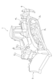
- FIG. 1 is a perspective view of a bulldozer 1, which is an example of a track-type work machine.
- FIG. 2 is a cross-sectional configuration diagram of the power transmission system of the bulldozer 1.
- FIG. 3 is a schematic system configuration diagram of the power transmission system of the bulldozer 1.
- the bulldozer 1 includes left and right traveling devices 4L and 4R having left and right sprockets 2L and 2R and left and right tracks 3L and 3R, a blade 5 provided at the front of the vehicle, and a ripper device 6 provided at the rear of the vehicle. Be prepared.
- the bulldozer 1 can perform work such as soil pushing by the blade 5 and work such as crushing and excavation by the ripper device 6.
- the bulldozer 1 includes an engine 10, a power transmission device 20, left and right planetary gear mechanisms 30L and 30R, left and right steering clutches 40L and 40R, left and right steering brakes 50L and 50R, and left and right output shafts 60L and 60R. It has left and right final deceleration devices 70L and 70R, and a lubricating oil supply unit 80.
- the power transmission device 20 transmits the power from the engine 10 to the left and right planetary gear mechanisms 30L and 30R.
- the power transmission device 20 includes a power take-off device (power take-off) 21, a torque converter 22, a transmission 23, a pinion 24, a bevel gear 25, and an input shaft 26.
- the power extraction device 21 distributes the power from the engine 10 to the torque converter 22 and the lubricating oil supply unit 80.
- the torque converter 22 transmits the power of the engine 10 transmitted from the power extraction device 21 to the transmission 23 via a fluid.
- the transmission 23 shifts the rotational motion transmitted from the torque converter 22.
- the transmission 23 can be switched between forward and reverse.
- the transmission 23 is connected to the pinion 24.
- the power from the transmission 23 is transmitted to the input shaft 26 via the pinion 24 and the bevel gear 25.
- the left and right planetary gear mechanisms 30L and 30R are arranged between the input shaft 26 and the left and right output shafts 60L and 60R.
- the left and right planetary gear mechanisms 30L and 30R have left and right ring gears 31L and 31R, left and right planetary gears 32L and 32R, left and right sun gears 33L and 33R, and left and right carriers 34L and 34R.
- the left and right ring gears 31L and 31R are connected to the input shaft 26.
- the left and right planetary gears 32L and 32R are arranged inside the left and right ring gears 31L and 31R in the radial direction perpendicular to the axis of the input shaft 26.
- the left and right planetary gears 32L and 32R are arranged between the left and right ring gears 31L and 31R and the left and right sun gears 33L and 33R.
- the left and right planetary gears 32L and 32R mesh with the left and right ring gears 31L and 31R and the left and right sun gears 33L and 33R.
- the left and right sun gears 33L and 33R are rotatably attached to the input shaft 26.
- the left and right sun gears 33L and 33R are arranged inside the left and right planetary gears 32L and 32R in the radial direction.
- the left and right sun gears 33L and 33R are connected to the left and right steering clutches 40L and 40R.
- the left and right carriers 34L and 34R are connected to the left and right planetary gears 32L and 32R and the left and right output shafts 60L and 60R.
- the left and right steering clutches 40L and 40R are wet multi-plate clutches that can be engaged with or released from the left and right sun gears 33L and 33R.
- the left and right steering clutches 40L and 40R switch between transmission and interruption of rotational power from the input shaft 26 by the left and right planetary gear mechanisms 30L and 30R to the left and right output shafts 60L and 60R.
- the left steering clutch 40L when the left steering clutch 40L is engaged and the left sun gear 33L is directly connected to the first clutch gear 91, the first clutch gear 91 is non-rotatable (described later), so that the left sun gear 33L is also non-rotatable. .. Then, the rotation of the input shaft 26 is transmitted to the left output shaft 60L via the left ring gear 31L, the left planetary gear 32L, and the left carrier 34L. Further, when the left steering clutch 40L is released and the left sun gear 33L is in a free rotation state, the rotation from the input shaft 26 to the left output shaft 60L is cut off. Similarly, the right steering clutch 40R also switches between transmission and disconnection of rotation from the input shaft 26 to the right output shaft 60R according to its engagement and disengagement.
- the first clutch gear 91 is attached to the left steering clutch 40L, and the first clutch gear 91 is connected to the idler gear 93 and the pinion gear 94.
- a second clutch gear 92 is attached to the right steering clutch 40R, and the second clutch gear 92 passes through the idler gear 93 and the pinion via the first transfer gear 95, the auxiliary shaft 96 and the second transfer gear 97. It is connected to the gear 94.
- the pinion shaft 94a connected to the pinion gear 94 is fixed by the fixing member 98 and cannot rotate. Therefore, rotational power is not applied from the left and right steering clutches 40L and 40R to the left and right sun gears 33L and 33R.
- the fixing member 98 is detachably fixed to a housing (not shown).
- the fixing member 98 is also removable from the pinion gear 94. As a result, the fixing of the pinion gear 94 by the fixing member 98 is released.
- a turning motor (not shown) may be connected to the pinion shaft 94a.
- the left and right steering clutches 40L and 40R are engaged and the rotational power of the turning motor is transmitted to the left and right sun gears 33L and 33R via the left and right steering clutches 40L and 40R, the left and right sun gears 33L , 33R reversely rotate at the same rotation speed.
- a difference in rotation speed occurs between the left and right output shafts 60L and 60R, and the bulldozer 1 can slowly turn left and right.
- the left and right steering brakes 50L and 50R brake the rotation of the left and right output shafts 60L and 60R.
- the left and right steering brakes 50L and 50R are wet multi-plate clutches that can be engaged with or released from the left and right output shafts 60L and 60R.
- the lubricating oil supply unit 80 includes a hydraulic pump 81, a lubricating oil passage 82, and a lubricating oil tank 83.
- the hydraulic pump 81 is driven by the power of the engine 10 transmitted from the power extraction device 21.
- the hydraulic pump 81 discharges lubricating oil from the lubricating oil tank 83 to the lubricating oil passage 82.
- the hydraulic pump 81 is a fixed capacity pump.
- the lubricating oil passage 82 includes a first supply oil passage 100, a second supply oil passage 110, left and right first oil passages 101L and 101R, left and right second oil passages 102L and 102R, and left and right third oil passages. It includes 103L, 103R, left and right fourth oil passages 104L, 104R, left and right fifth oil passages 105L, 105R, and left and right discharge oil passages 106L, 106R.
- the first supply oil passage 100 is connected to the second supply oil passage 110, each of the left and right first oil passages 101L and 101R, and the hydraulic pump 81.
- the first supply oil passage 100 supplies the lubricating oil discharged from the hydraulic pump 81 to the second supply oil passage 110 and the left and right first oil passages 101L and 101R.
- the left and right first oil passages 101L and 101R guide a part of the lubricating oil discharged from the hydraulic pump 81 to the left and right steering brakes 50L and 50R.
- the second supply oil passage 110 is connected to the first supply oil passage 100 and the inside of the input shaft 26.
- the second supply oil passage 110 guides a part of the lubricating oil discharged from the hydraulic pump 81 to the left and right second oil passages 102L and 102R and the left and right fourth oil passages 104L and 104R.
- the left and right second oil passages 102L and 102R guide a part of the lubricating oil discharged from the hydraulic pump 81 to the left and right planetary gear mechanisms 30L and 30R.
- the left and right third oil passages 103L and 103R guide at least a part of the lubricating oil that has passed through the left and right planetary gear mechanisms 30L and 30R to the left and right steering brakes 50L and 50R.
- the left and right third oil passages 103L and 103R guide all of the lubricating oil that has passed through the left and right planetary gear mechanisms 30L and 30R to the left and right steering brakes 50L and 50R.
- the left and right fourth oil passages 104L and 104R guide a part of the lubricating oil discharged from the hydraulic pump 81 to the left and right steering clutches 40L and 40R.
- the left and right fifth oil passages 105L and 105R guide at least a part of the lubricating oil that has passed through the left and right steering clutches 40L and 40R to the left and right steering brakes 50L and 50R.
- the left and right fifth oil passages 105L and 105R are lubricating oils that have passed through the left and right steering clutches 40L and 40R via the left and right planetary gear mechanisms 30L and 30R and the left and right third oil passages 103L and 103R. Lead all of the above to the left and right steering brakes 50L and 50R.
- all of the lubricating oils guided to the left and right planetary gear mechanisms 30L and 30R and the steering clutches 40L and 40R are all the left and right third oil passages 103L and 103R and the left and right fifth oil passages. It is guided to the left and right steering brakes 50L and 50R via 105L and 105R.
- the left and right discharge oil passages 106L and 106R guide the lubricating oil that has passed through the left and right steering brakes 50L and 50R to the lubricating oil tank 83.
- FIG. 4 is a cross-sectional view showing the configuration around the lubricating oil passage 82.
- a cross section perpendicular to the axis of the input shaft 26 is shown. Since the configuration around the lubricating oil passage 82 is basically symmetrical, the configuration on the right side will be described below.
- the right steering clutch 40R has a rotating member 41, a clutch housing 42, a plurality of clutch discs 43, a plurality of clutch plates 44, and a clutch piston 45.
- the rotating member 41 is supported by the input shaft 26 and rotates around the axis of the input shaft 26.
- the clutch housing 42 is installed so as to be rotatable relative to the rotating member 41.
- the clutch housing 42 surrounds the outside of each clutch disc 43 and each clutch plate 44.
- Each clutch disc 43 is supported by a rotating member 41.
- Each clutch plate 44 is supported by a clutch housing 42.
- the clutch discs 43 and the clutch plates 44 are alternately arranged in the axial direction parallel to the axis of the input shaft 26.
- the right steering brake 50R has a rotating member 51, a brake housing 52, a plurality of fixing plates 53, a plurality of brake discs 54, and a brake piston 55.
- the rotating member 51 is fixed to the right output shaft 60R and rotates around the axis of the right output shaft 60R.
- the brake housing 52 can rotate relative to the rotating member 51. In the present embodiment, the brake housing 52 is fixed, and the brake housing 52 itself does not rotate.
- the brake housing 52 surrounds the outside of each fixing plate 53 and each brake disc 54.
- Each fixing plate 53 is attached to the brake housing 52.
- Each fixing plate 53 may move slightly axially with respect to the brake housing 52.
- Each brake disc 54 is supported by a rotating member 51.
- Each brake disc 54 may move slightly in the axial direction with respect to the rotating member 51.
- Each fixed plate 53 and each brake disc 54 are arranged alternately in the axial direction.
- Each fixing plate 53 and each brake disc 54 are pressure-welded by a spring (for example, a disc spring, a coil spring, etc.) (not shown).
- the brake piston 55 separates each fixing plate 53 and each brake disc 54 from each other when hydraulic oil is supplied. As a result, the right steering brake 50R is in a non-braking state.
- the right planetary gear mechanism 30R is arranged inside the right steering brake 50R in the radial direction.
- the right ring gear 31R is arranged inside each brake disc 54 in the radial direction.
- the right planetary gear 32R and the right sun gear 33R arranged inside the right ring gear 31R are also arranged inside the brake discs 54 in the radial direction.
- a part of the right carrier 34R connected to the right planetary gear 32R and the right output shaft 60R is also arranged inside the brake disc 54 in the radial direction.
- each clutch disc 43 and each clutch plate 44 are arranged inside each brake disc 54 in the radial direction.
- the X member and the X member are viewed from an axial direction parallel to the axis of the input shaft 26. It means that the shortest distance from the axis is shorter than the shortest distance between the Y member and the axis. In this case, the position of the X member in the axial direction and the position of the Y member in the axial direction may or may not partially overlap.
- the right steering brake 50R, the right planetary gear mechanism 30R, and the right steering clutch 40R are arranged in this order from the right side, but the arrangement order in the axial direction can be changed as appropriate.
- FIG. 5 is a schematic diagram for explaining the flow of the lubricating oil.
- the lubricating oil discharged from the hydraulic pump 81 passes through the first supply oil passage 100 and the second supply oil passage 110 to the right first oil passage 101R, the right second oil passage 102R, and the right fourth oil passage 104R, respectively. Will be distributed.
- the distribution ratio to each oil passage can be appropriately adjusted by changing the diameter of each oil passage.
- the lubricating oil distributed to the right fourth oil passage 104R lubricates the right steering clutch 40R, and then is guided from the right fifth oil passage 105R to the right planetary gear mechanism 30R by centrifugal force.
- the lubricating oil distributed to the right second oil passage 102R lubricates the right planetary gear mechanism 30R, and then, together with the lubricating oil guided from the right fifth oil passage 105R to the right planetary gear mechanism 30R, the right third oil passage by centrifugal force. It is guided from the oil passage 103R to the right steering brake 50R.
- the lubricating oil distributed to the right first oil passage 101R lubricates the right steering brake 50R together with the lubricating oil guided from the right third oil passage 103R to the right steering brake 50R, and then from the right exhaust oil passage 106R by centrifugal force. It is guided to the lubricating oil tank 83.
- the bulldozer 1 includes a right first oil passage 101R, a right second oil passage 102R, and a right third oil passage 103R.
- the right first oil passage 101R guides a part of the lubricating oil discharged from the hydraulic pump 81 to the right steering brake 50R.
- the right second oil passage 102R guides a part of the lubricating oil discharged from the hydraulic pump 81 to the right planetary gear mechanism 30R.
- the right third oil passage 103R guides at least a part of the lubricating oil that has passed through the right planetary gear mechanism 30R to the right steering brake 50R.
- At least a part of the right planetary gear mechanism 30R is arranged inside the right steering brake 50R in the radial direction perpendicular to the axis of the input shaft 26.
- the lubricating oil can be guided from the right planetary gear mechanism 30R to the right steering brake 50R via the third oil passage 103R by centrifugal force, the lubricating oil used for lubricating the right planetary gear mechanism 30R is used to the right. It can also be used for lubrication of the steering brake 50R. Therefore, the lubricating oil supplied from the hydraulic pump 81 can be efficiently used, and the capacity of the hydraulic pump 81 can be reduced. This effect can be similarly obtained with the left steering brake 50L.
- the bulldozer 1 includes a right fourth oil passage 104R and a right fifth oil passage 105R.
- the right fourth oil passage 104R guides a part of the lubricating oil discharged from the hydraulic pump 81 to the right steering clutch 40R.
- the right fifth oil passage 105R guides at least a part of the lubricating oil that has passed through the right steering clutch 40R to the right steering brake 50R. At least a part of the right steering clutch 40R is arranged inside the right steering brake 50R in the radial direction.
- the lubricating oil can be guided from the right steering clutch 40R to the right steering brake 50R via the fifth oil passage 105R by centrifugal force, the lubricating oil used for lubricating the right steering clutch 40R can be used as the right steering brake. It can also be used for lubrication of 50R. Therefore, the lubricating oil supplied from the hydraulic pump 81 can be used more efficiently, and the capacity of the hydraulic pump 81 can be further reduced. This effect can be similarly obtained with the left steering brake 50L.
- the left and right third oil passages 103L and 103R guide all the lubricating oil that has passed through the left and right planetary gear mechanisms 30L and 30R to the left and right steering brakes 50L and 50R, but the present invention is limited to this. No.
- the left and right third oil passages 103L and 103R may guide only a part of the lubricating oil that has passed through the left and right planetary gear mechanisms 30L and 30R to the left and right steering brakes 50L and 50R. In this case, the remaining portion of the lubricating oil that has passed through the left and right planetary gear mechanisms 30L and 30R may be directly collected in the lubricating oil tank 83.
- the left and right fifth oil passages 105L and 105R guide all the lubricating oil that has passed through the left and right steering clutches 40L and 40R to the left and right steering brakes 50L and 50R, but the present invention is not limited to this. ..
- the left and right fifth oil passages 105L and 105R may guide only a part of the lubricating oil that has passed through the left and right steering clutches 40L and 40R to the left and right steering brakes 50L and 50R. In this case, the remaining portion of the lubricating oil that has passed through the left and right steering clutches 40L and 40R may be directly collected in the lubricating oil tank 83.
- the left and right fifth oil passages 105L and 105R are connected to the left and right planetary gear mechanisms 30L and 30R from the left and right steering clutches 40L and 40R, but the present invention is not limited to this.
- the left and right fifth oil passages 105L and 105R may be directly connected to the left and right steering brakes 50L and 50R from the left and right steering clutches 40L and 40R.
- the left and right fifth oil passages 105L and 105R may be directly connected to the lubricating oil tank 83 from the left and right steering clutches 40L and 40R.
Landscapes
- Engineering & Computer Science (AREA)
- General Engineering & Computer Science (AREA)
- Mechanical Engineering (AREA)
- Mining & Mineral Resources (AREA)
- Civil Engineering (AREA)
- Structural Engineering (AREA)
- Chemical & Material Sciences (AREA)
- Combustion & Propulsion (AREA)
- Transportation (AREA)
- Non-Deflectable Wheels, Steering Of Trailers, Or Other Steering (AREA)
- General Details Of Gearings (AREA)
Abstract
In the present invention, a bulldozer (1) comprises: a first right oil passage (101R), a second right oil passage (102R), and a third right oil passage (103R). The first right oil passage (101R) guides some of lubricating oil discharged from a hydraulic pump (81) to a right steering brake (50R). The second right oil passage (102R) guides some of the lubricating oil discharged from the hydraulic pump (81) to a right planetary gear structure (30R). The third right oil passage (103R) guides at least some of the lubricating oil that has passed through the right planetary gear structure (30R) to the right steering brake (50R). At least a part of the right planetary gear structure (30R) is arranged further inside than the right steering brake (50R) in a radial direction perpendicular to the shaft center of an input shaft (26).
Description
本開示は、履帯式作業機械に関する。
This disclosure relates to track-type work machines.
履帯式作業機械(例えば、ブルドーザなど)においては、エンジンの動力がトランスミッションを介して左右の駆動輪に伝達され、左右の駆動輪によって左右の履帯が駆動される。このような履帯式作業機械では、左右の駆動輪に対応して設けられた左右のステアリングクラッチ及びステアリングブレーキを油圧制御することによって、左右の旋回が実行される。
In a track-type work machine (for example, a bulldozer), the power of the engine is transmitted to the left and right drive wheels via a transmission, and the left and right drive wheels drive the left and right tracks. In such a track-type work machine, left and right turning is executed by hydraulically controlling the left and right steering clutches and steering brakes provided corresponding to the left and right drive wheels.
特許文献1では、潤滑油を効率的に利用することを目的として、油圧ポンプからステアリングクラッチに供給された潤滑油の一部をステアリングブレーキに供給する手法が提案されている。
Patent Document 1 proposes a method of supplying a part of the lubricating oil supplied from the hydraulic pump to the steering clutch to the steering brake for the purpose of efficiently using the lubricating oil.
ところで、ステアリングクラッチを小型化するには、入力軸と出力軸との間に遊星歯車機構を設けることが考えられるが、特許文献1では、遊星歯車機構を設けた場合における潤滑油の効率的な利用については検討されていない。
By the way, in order to reduce the size of the steering clutch, it is conceivable to provide a planetary gear mechanism between the input shaft and the output shaft. However, in Patent Document 1, the efficiency of the lubricating oil when the planetary gear mechanism is provided is efficient. The use has not been considered.
本開示の課題は、潤滑油を効率的に利用可能な履帯式作業機械を提供することである。
The subject of this disclosure is to provide a track-type work machine that can efficiently use lubricating oil.
本開示の一側面に係る履帯式作業機械は、遊星歯車機構と、ステアリングクラッチと、ステアリングブレーキと、油圧ポンプと、第1油路と、第2油路と、第3油路とを備える。遊星歯車機構は、入力軸と出力軸との間に配置される。ステアリングクラッチは、遊星歯車機構による入力軸から出力軸への回転の伝達及び遮断を切り替える。ステアリングブレーキは、出力軸の回転を制動する。油圧ポンプは、潤滑油を吐出する。第1油路は、油圧ポンプから吐出される潤滑油の一部をステアリングブレーキに導く。第2油路は、油圧ポンプから吐出される潤滑油の一部を遊星歯車機構に導く。第3油路は、遊星歯車機構を通過した潤滑油の少なくとも一部をステアリングブレーキに導く。遊星歯車機構の少なくとも一部は、入力軸の軸心に垂直な径方向において、ステアリングブレーキよりも内側に配置される。
The belt-type work machine according to one aspect of the present disclosure includes a planetary gear mechanism, a steering clutch, a steering brake, a hydraulic pump, a first oil passage, a second oil passage, and a third oil passage. The planetary gear mechanism is arranged between the input shaft and the output shaft. The steering clutch switches between transmission and interruption of rotation from the input shaft to the output shaft by the planetary gear mechanism. The steering brake brakes the rotation of the output shaft. The hydraulic pump discharges lubricating oil. The first oil passage guides a part of the lubricating oil discharged from the hydraulic pump to the steering brake. The second oil passage guides a part of the lubricating oil discharged from the hydraulic pump to the planetary gear mechanism. The third oil passage guides at least a part of the lubricating oil that has passed through the planetary gear mechanism to the steering brake. At least a portion of the planetary gear mechanism is located inside the steering brake in the radial direction perpendicular to the axis of the input shaft.
本開示に係る履帯式作業機械によれば、潤滑油を効率的に利用することができる。
According to the track-type work machine according to the present disclosure, the lubricating oil can be used efficiently.
(ブルドーザ1の構成)
図1は、履帯式作業機械の一例であるブルドーザ1の斜視図である。図2は、ブルドーザ1の動力伝達系統の断面構成図である。図3は、ブルドーザ1の動力伝達系統の概略システム構成図である。 (Structure of bulldozer 1)
FIG. 1 is a perspective view of a bulldozer 1, which is an example of a track-type work machine. FIG. 2 is a cross-sectional configuration diagram of the power transmission system of the bulldozer 1. FIG. 3 is a schematic system configuration diagram of the power transmission system of the bulldozer 1.
ブルドーザ1は、左右のスプロケット2L,2R及び左右の履帯3L,3Rを有する左右の走行装置4L,4Rと、車両前部に設けられたブレード5と、車両後部に設けられたリッパ装置6とを備える。
The bulldozer 1 includes left and right traveling devices 4L and 4R having left and right sprockets 2L and 2R and left and right tracks 3L and 3R, a blade 5 provided at the front of the vehicle, and a ripper device 6 provided at the rear of the vehicle. Be prepared.
ブルドーザ1は、ブレード5による土押し等の作業や、リッパ装置6による破砕及び掘削等の作業を行うことができる。
The bulldozer 1 can perform work such as soil pushing by the blade 5 and work such as crushing and excavation by the ripper device 6.
ブルドーザ1は、エンジン10と、動力伝達装置20と、左右の遊星歯車機構30L,30Rと、左右のステアリングクラッチ40L,40Rと、左右のステアリングブレーキ50L,50Rと、左右の出力軸60L,60Rと、左右の終減速装置70L,70Rと、潤滑油供給部80とを有する。
The bulldozer 1 includes an engine 10, a power transmission device 20, left and right planetary gear mechanisms 30L and 30R, left and right steering clutches 40L and 40R, left and right steering brakes 50L and 50R, and left and right output shafts 60L and 60R. It has left and right final deceleration devices 70L and 70R, and a lubricating oil supply unit 80.
動力伝達装置20は、エンジン10からの動力を左右の遊星歯車機構30L,30Rに伝達する。動力伝達装置20は、動力取出装置(パワーテイクオフ)21と、トルクコンバータ22と、トランスミッション23と、ピニオン24と、ベベルギア25と、入力軸26とを含む。
The power transmission device 20 transmits the power from the engine 10 to the left and right planetary gear mechanisms 30L and 30R. The power transmission device 20 includes a power take-off device (power take-off) 21, a torque converter 22, a transmission 23, a pinion 24, a bevel gear 25, and an input shaft 26.
動力取出装置21は、エンジン10からの動力をトルクコンバータ22と潤滑油供給部80とに分配する。トルクコンバータ22は、動力取出装置21から伝達されるエンジン10の動力を、流体を介してトランスミッション23に伝達する。トランスミッション23は、トルクコンバータ22から伝達される回転運動を変速する。トランスミッション23は、前進と後進に切り替え可能である。トランスミッション23は、ピニオン24に連結される。トランスミッション23からの動力は、ピニオン24及びベベルギア25を介して、入力軸26に伝達される。
The power extraction device 21 distributes the power from the engine 10 to the torque converter 22 and the lubricating oil supply unit 80. The torque converter 22 transmits the power of the engine 10 transmitted from the power extraction device 21 to the transmission 23 via a fluid. The transmission 23 shifts the rotational motion transmitted from the torque converter 22. The transmission 23 can be switched between forward and reverse. The transmission 23 is connected to the pinion 24. The power from the transmission 23 is transmitted to the input shaft 26 via the pinion 24 and the bevel gear 25.
左右の遊星歯車機構30L,30Rは、入力軸26と左右の出力軸60L,60Rとの間に配置される。左右の遊星歯車機構30L,30Rは、左右のリングギア31L,31R、左右のプラネタリギア32L,32R、左右のサンギア33L,33R及び左右のキャリア34L,34Rを有する。
The left and right planetary gear mechanisms 30L and 30R are arranged between the input shaft 26 and the left and right output shafts 60L and 60R. The left and right planetary gear mechanisms 30L and 30R have left and right ring gears 31L and 31R, left and right planetary gears 32L and 32R, left and right sun gears 33L and 33R, and left and right carriers 34L and 34R.
左右のリングギア31L,31Rは、入力軸26に連結される。左右のプラネタリギア32L,32Rは、入力軸26の軸心に垂直な径方向において、左右のリングギア31L,31Rの内側に配置される。左右のプラネタリギア32L,32Rは、左右のリングギア31L,31Rと左右のサンギア33L,33Rとの間に配置される。左右のプラネタリギア32L,32Rは、左右のリングギア31L,31Rと左右のサンギア33L,33Rとに噛み合っている。左右のサンギア33L,33Rは、入力軸26に対して回転自在に取り付けられる。左右のサンギア33L,33Rは、径方向において、左右のプラネタリギア32L,32Rの内側に配置される。左右のサンギア33L,33Rは、左右のステアリングクラッチ40L,40Rに連結される。左右のキャリア34L,34Rは、左右のプラネタリギア32L,32Rと左右の出力軸60L,60Rとに連結される。
The left and right ring gears 31L and 31R are connected to the input shaft 26. The left and right planetary gears 32L and 32R are arranged inside the left and right ring gears 31L and 31R in the radial direction perpendicular to the axis of the input shaft 26. The left and right planetary gears 32L and 32R are arranged between the left and right ring gears 31L and 31R and the left and right sun gears 33L and 33R. The left and right planetary gears 32L and 32R mesh with the left and right ring gears 31L and 31R and the left and right sun gears 33L and 33R. The left and right sun gears 33L and 33R are rotatably attached to the input shaft 26. The left and right sun gears 33L and 33R are arranged inside the left and right planetary gears 32L and 32R in the radial direction. The left and right sun gears 33L and 33R are connected to the left and right steering clutches 40L and 40R. The left and right carriers 34L and 34R are connected to the left and right planetary gears 32L and 32R and the left and right output shafts 60L and 60R.
左右のステアリングクラッチ40L,40Rは、左右のサンギア33L,33Rに対して係合又は開放可能な湿式多板式クラッチである。左右のステアリングクラッチ40L,40Rは、左右の遊星歯車機構30L,30Rによる入力軸26から左右の出力軸60L,60Rへの回転動力の伝達及び遮断を切り替える。
The left and right steering clutches 40L and 40R are wet multi-plate clutches that can be engaged with or released from the left and right sun gears 33L and 33R. The left and right steering clutches 40L and 40R switch between transmission and interruption of rotational power from the input shaft 26 by the left and right planetary gear mechanisms 30L and 30R to the left and right output shafts 60L and 60R.
具体的には、左ステアリングクラッチ40Lが係合されて左サンギア33Lが第1クラッチギア91と直結すると、第1クラッチギア91は回転不能(後述)であるため、左サンギア33Lも回転不能になる。すると、入力軸26の回転は、左リングギア31L、左プラネタリギア32L及び左キャリア34Lを介して左出力軸60Lに伝達される。また、左ステアリングクラッチ40Lが開放されて左サンギア33Lが自由回転状態になると、入力軸26から左出力軸60Lへの回転は遮断される。同様に、右ステアリングクラッチ40Rも、その係合及び開放に応じて、入力軸26から右出力軸60Rへの回転の伝達及び遮断を切り替える。
Specifically, when the left steering clutch 40L is engaged and the left sun gear 33L is directly connected to the first clutch gear 91, the first clutch gear 91 is non-rotatable (described later), so that the left sun gear 33L is also non-rotatable. .. Then, the rotation of the input shaft 26 is transmitted to the left output shaft 60L via the left ring gear 31L, the left planetary gear 32L, and the left carrier 34L. Further, when the left steering clutch 40L is released and the left sun gear 33L is in a free rotation state, the rotation from the input shaft 26 to the left output shaft 60L is cut off. Similarly, the right steering clutch 40R also switches between transmission and disconnection of rotation from the input shaft 26 to the right output shaft 60R according to its engagement and disengagement.
なお、図3に示すように、左ステアリングクラッチ40Lには、第1クラッチギア91が取り付けられており、第1クラッチギア91は、アイドラギア93及びピニオンギア94に連結されている。また、右ステアリングクラッチ40Rには、第2クラッチギア92が取り付けられており、第2クラッチギア92は、第1トランスファギア95、副軸96及び第2トランスファギア97を介して、アイドラギア93及びピニオンギア94に連結されている。そして、ピニオンギア94に連結されたピニオン軸94aは、固定部材98によって固定されて回転不能である。そのため、左右のステアリングクラッチ40L,40Rから左右のサンギア33L,33Rに回転動力が加えられることはない。
As shown in FIG. 3, the first clutch gear 91 is attached to the left steering clutch 40L, and the first clutch gear 91 is connected to the idler gear 93 and the pinion gear 94. Further, a second clutch gear 92 is attached to the right steering clutch 40R, and the second clutch gear 92 passes through the idler gear 93 and the pinion via the first transfer gear 95, the auxiliary shaft 96 and the second transfer gear 97. It is connected to the gear 94. The pinion shaft 94a connected to the pinion gear 94 is fixed by the fixing member 98 and cannot rotate. Therefore, rotational power is not applied from the left and right steering clutches 40L and 40R to the left and right sun gears 33L and 33R.
ここで、固定部材98は、図示しないハウジングに着脱可能に固定されている。固定部材98をハウジングから取り外した場合、固定部材98は、ピニオンギア94からも取り外し可能である。これにより、固定部材98によるピニオンギア94の固定は解除される。
Here, the fixing member 98 is detachably fixed to a housing (not shown). When the fixing member 98 is removed from the housing, the fixing member 98 is also removable from the pinion gear 94. As a result, the fixing of the pinion gear 94 by the fixing member 98 is released.
固定部材98によるピニオンギア94の固定を解除した場合、ピニオン軸94aには旋回用モータ(不図示)を連結してもよい。この場合、左右のステアリングクラッチ40L,40Rが係合され、かつ、旋回用モータの回転動力が左右のステアリングクラッチ40L,40Rを介して左右のサンギア33L,33Rに伝達されると、左右のサンギア33L,33Rが同じ回転数で逆回転する。これによって、左右の出力軸60L,60Rに回転数差が生じて、ブルドーザ1は左右に緩旋回することができる。
When the pinion gear 94 is released from the fixing member 98, a turning motor (not shown) may be connected to the pinion shaft 94a. In this case, when the left and right steering clutches 40L and 40R are engaged and the rotational power of the turning motor is transmitted to the left and right sun gears 33L and 33R via the left and right steering clutches 40L and 40R, the left and right sun gears 33L , 33R reversely rotate at the same rotation speed. As a result, a difference in rotation speed occurs between the left and right output shafts 60L and 60R, and the bulldozer 1 can slowly turn left and right.
左右のステアリングブレーキ50L,50Rは、左右の出力軸60L,60Rの回転を制動する。左右のステアリングブレーキ50L,50Rは、左右の出力軸60L,60Rに対して係合又は開放可能な湿式多板式クラッチである。
The left and right steering brakes 50L and 50R brake the rotation of the left and right output shafts 60L and 60R. The left and right steering brakes 50L and 50R are wet multi-plate clutches that can be engaged with or released from the left and right output shafts 60L and 60R.
左ステアリングブレーキ50Lが係合されると、左出力軸60Lの回転が制動される。その結果、左スプロケット2Lに連結された左終減速装置70Lの回転が低減される。右ステアリングブレーキ50Rが係合されると、右出力軸60Rの回転が制動される。その結果、右スプロケット2Rに連結された右終減速装置70Rの回転が低減される。
When the left steering brake 50L is engaged, the rotation of the left output shaft 60L is damped. As a result, the rotation of the left final speed reducer 70L connected to the left sprocket 2L is reduced. When the right steering brake 50R is engaged, the rotation of the right output shaft 60R is damped. As a result, the rotation of the right final speed reducer 70R connected to the right sprocket 2R is reduced.
潤滑油供給部80は、油圧ポンプ81と、潤滑油路82と、潤滑油タンク83とを有する。
The lubricating oil supply unit 80 includes a hydraulic pump 81, a lubricating oil passage 82, and a lubricating oil tank 83.
油圧ポンプ81は、動力取出装置21から伝達されるエンジン10の動力によって駆動される。油圧ポンプ81は、潤滑油タンク83から潤滑油路82に潤滑油を吐出する。本実施形態において、油圧ポンプ81は、固定容量型ポンプである。
The hydraulic pump 81 is driven by the power of the engine 10 transmitted from the power extraction device 21. The hydraulic pump 81 discharges lubricating oil from the lubricating oil tank 83 to the lubricating oil passage 82. In the present embodiment, the hydraulic pump 81 is a fixed capacity pump.
潤滑油路82は、第1供給油路100と、第2供給油路110と、左右の第1油路101L,101Rと、左右の第2油路102L,102Rと、左右の第3油路103L,103Rと、左右の第4油路104L,104Rと、左右の第5油路105L,105Rと、左右の排出油路106L,106Rとを含む。
The lubricating oil passage 82 includes a first supply oil passage 100, a second supply oil passage 110, left and right first oil passages 101L and 101R, left and right second oil passages 102L and 102R, and left and right third oil passages. It includes 103L, 103R, left and right fourth oil passages 104L, 104R, left and right fifth oil passages 105L, 105R, and left and right discharge oil passages 106L, 106R.
第1供給油路100は、第2供給油路110及び左右の第1油路101L,101Rそれぞれと油圧ポンプ81とに連なる。第1供給油路100は、油圧ポンプ81から吐出される潤滑油を、第2供給油路110及び左右の第1油路101L,101Rに供給する。
The first supply oil passage 100 is connected to the second supply oil passage 110, each of the left and right first oil passages 101L and 101R, and the hydraulic pump 81. The first supply oil passage 100 supplies the lubricating oil discharged from the hydraulic pump 81 to the second supply oil passage 110 and the left and right first oil passages 101L and 101R.
左右の第1油路101L,101Rは、油圧ポンプ81から吐出される潤滑油の一部を左右のステアリングブレーキ50L,50Rに導く。
The left and right first oil passages 101L and 101R guide a part of the lubricating oil discharged from the hydraulic pump 81 to the left and right steering brakes 50L and 50R.
第2供給油路110は、第1供給油路100と入力軸26の内部とに連なる。第2供給油路110は、油圧ポンプ81から吐出される潤滑油の一部を、左右の第2油路102L,102Rと左右の第4油路104L,104Rとに導く。
The second supply oil passage 110 is connected to the first supply oil passage 100 and the inside of the input shaft 26. The second supply oil passage 110 guides a part of the lubricating oil discharged from the hydraulic pump 81 to the left and right second oil passages 102L and 102R and the left and right fourth oil passages 104L and 104R.
左右の第2油路102L,102Rは、油圧ポンプ81から吐出される潤滑油の一部を左右の遊星歯車機構30L,30Rに導く。左右の第3油路103L,103Rは、左右の遊星歯車機構30L,30Rを通過した潤滑油の少なくとも一部を左右のステアリングブレーキ50L,50Rに導く。本実施形態において、左右の第3油路103L,103Rは、左右の遊星歯車機構30L,30Rを通過した潤滑油の全部を左右のステアリングブレーキ50L,50Rに導く。
The left and right second oil passages 102L and 102R guide a part of the lubricating oil discharged from the hydraulic pump 81 to the left and right planetary gear mechanisms 30L and 30R. The left and right third oil passages 103L and 103R guide at least a part of the lubricating oil that has passed through the left and right planetary gear mechanisms 30L and 30R to the left and right steering brakes 50L and 50R. In the present embodiment, the left and right third oil passages 103L and 103R guide all of the lubricating oil that has passed through the left and right planetary gear mechanisms 30L and 30R to the left and right steering brakes 50L and 50R.
左右の第4油路104L,104Rは、油圧ポンプ81から吐出される潤滑油の一部を左右のステアリングクラッチ40L,40Rに導く。左右の第5油路105L,105Rは、左右のステアリングクラッチ40L,40Rを通過した潤滑油の少なくとも一部を左右のステアリングブレーキ50L,50Rに導く。具体的には、左右の第5油路105L,105Rは、左右の遊星歯車機構30L,30R及び左右の第3油路103L,103Rを介して、左右のステアリングクラッチ40L,40Rを通過した潤滑油の全部を左右のステアリングブレーキ50L,50Rに導く。
The left and right fourth oil passages 104L and 104R guide a part of the lubricating oil discharged from the hydraulic pump 81 to the left and right steering clutches 40L and 40R. The left and right fifth oil passages 105L and 105R guide at least a part of the lubricating oil that has passed through the left and right steering clutches 40L and 40R to the left and right steering brakes 50L and 50R. Specifically, the left and right fifth oil passages 105L and 105R are lubricating oils that have passed through the left and right steering clutches 40L and 40R via the left and right planetary gear mechanisms 30L and 30R and the left and right third oil passages 103L and 103R. Lead all of the above to the left and right steering brakes 50L and 50R.
このように、本実施形態では、左右の遊星歯車機構30L,30R及びステアリングクラッチ40L,40Rそれぞれに導かれた潤滑油の全部が、左右の第3油路103L,103R及び左右の第5油路105L,105Rを介して、左右のステアリングブレーキ50L,50Rに導かれる。
As described above, in the present embodiment, all of the lubricating oils guided to the left and right planetary gear mechanisms 30L and 30R and the steering clutches 40L and 40R are all the left and right third oil passages 103L and 103R and the left and right fifth oil passages. It is guided to the left and right steering brakes 50L and 50R via 105L and 105R.
左右の排出油路106L,106Rは、左右のステアリングブレーキ50L,50Rを通過した潤滑油を潤滑油タンク83に導く。
The left and right discharge oil passages 106L and 106R guide the lubricating oil that has passed through the left and right steering brakes 50L and 50R to the lubricating oil tank 83.
(潤滑油路82周辺の構成)
図4は、潤滑油路82周辺の構成を示す断面図である。図4では、入力軸26の軸心に垂直な断面が図示されている。潤滑油路82周辺の構成は基本的に左右対称であるため、以下においては右側の構成について説明する。 (Structure around the lubricating oil passage 82)
FIG. 4 is a cross-sectional view showing the configuration around the lubricatingoil passage 82. In FIG. 4, a cross section perpendicular to the axis of the input shaft 26 is shown. Since the configuration around the lubricating oil passage 82 is basically symmetrical, the configuration on the right side will be described below.
図4は、潤滑油路82周辺の構成を示す断面図である。図4では、入力軸26の軸心に垂直な断面が図示されている。潤滑油路82周辺の構成は基本的に左右対称であるため、以下においては右側の構成について説明する。 (Structure around the lubricating oil passage 82)
FIG. 4 is a cross-sectional view showing the configuration around the lubricating
右ステアリングクラッチ40Rは、回転部材41、クラッチハウジング42、複数のクラッチディスク43、複数のクラッチプレート44、及びクラッチピストン45を有する。
The right steering clutch 40R has a rotating member 41, a clutch housing 42, a plurality of clutch discs 43, a plurality of clutch plates 44, and a clutch piston 45.
回転部材41は、入力軸26に支持されており、入力軸26の軸心周りに回転する。クラッチハウジング42は、回転部材41に対して相対回転可能に設置されている。クラッチハウジング42は、各クラッチディスク43及び各クラッチプレート44の外側を取り囲む。各クラッチディスク43は、回転部材41に支持される。各クラッチプレート44は、クラッチハウジング42に支持される。各クラッチディスク43と各クラッチプレート44は、入力軸26の軸心に平行な軸方向において交互に配置される。クラッチピストン45は、作動油が供給されると各クラッチディスク43と各クラッチプレート44とを互いに圧接させる。これにより、右ステアリングクラッチ40Rは係合状態となる。
The rotating member 41 is supported by the input shaft 26 and rotates around the axis of the input shaft 26. The clutch housing 42 is installed so as to be rotatable relative to the rotating member 41. The clutch housing 42 surrounds the outside of each clutch disc 43 and each clutch plate 44. Each clutch disc 43 is supported by a rotating member 41. Each clutch plate 44 is supported by a clutch housing 42. The clutch discs 43 and the clutch plates 44 are alternately arranged in the axial direction parallel to the axis of the input shaft 26. When the hydraulic oil is supplied, the clutch piston 45 presses each clutch disc 43 and each clutch plate 44 against each other. As a result, the right steering clutch 40R is in an engaged state.
右ステアリングブレーキ50Rは、回転部材51、ブレーキハウジング52、複数の固定プレート53、複数のブレーキディスク54、及びブレーキピストン55を有する。
The right steering brake 50R has a rotating member 51, a brake housing 52, a plurality of fixing plates 53, a plurality of brake discs 54, and a brake piston 55.
回転部材51は、右出力軸60Rに固定されており、右出力軸60Rの軸心周りに回転する。ブレーキハウジング52は、回転部材51に対して相対回転可能である。本実施形態において、ブレーキハウジング52は固定されており、ブレーキハウジング52自体は回転しない。ブレーキハウジング52は、各固定プレート53及び各ブレーキディスク54の外側を取り囲む。各固定プレート53は、ブレーキハウジング52に取り付けられる。各固定プレート53は、ブレーキハウジング52に対して軸方向に若干移動してもよい。各ブレーキディスク54は、回転部材51に支持される。各ブレーキディスク54は、回転部材51に対して軸方向に若干移動してもよい。
The rotating member 51 is fixed to the right output shaft 60R and rotates around the axis of the right output shaft 60R. The brake housing 52 can rotate relative to the rotating member 51. In the present embodiment, the brake housing 52 is fixed, and the brake housing 52 itself does not rotate. The brake housing 52 surrounds the outside of each fixing plate 53 and each brake disc 54. Each fixing plate 53 is attached to the brake housing 52. Each fixing plate 53 may move slightly axially with respect to the brake housing 52. Each brake disc 54 is supported by a rotating member 51. Each brake disc 54 may move slightly in the axial direction with respect to the rotating member 51.
各固定プレート53と各ブレーキディスク54は、軸方向において交互に配置される。各固定プレート53と各ブレーキディスク54は、図示しないばね(例えば、皿ばね、コイルばねなど)によって圧接されている。ブレーキピストン55は、作動油が供給されると各固定プレート53と各ブレーキディスク54とを互いに離反させる。これにより、右ステアリングブレーキ50Rは非制動状態となる。
Each fixed plate 53 and each brake disc 54 are arranged alternately in the axial direction. Each fixing plate 53 and each brake disc 54 are pressure-welded by a spring (for example, a disc spring, a coil spring, etc.) (not shown). The brake piston 55 separates each fixing plate 53 and each brake disc 54 from each other when hydraulic oil is supplied. As a result, the right steering brake 50R is in a non-braking state.
ここで、右遊星歯車機構30Rの少なくとも一部は、径方向において、右ステアリングブレーキ50Rよりも内側に配置される。具体的には、右リングギア31Rは、径方向において、各ブレーキディスク54よりも内側に配置されている。また、右リングギア31Rの内側に配置されている右プラネタリギア32R及び右サンギア33Rも、径方向において、各ブレーキディスク54よりも内側に配置されている。更に、右プラネタリギア32Rと右出力軸60Rとに連結された右キャリア34Rの一部も、径方向において、各ブレーキディスク54よりも内側に配置されている。
Here, at least a part of the right planetary gear mechanism 30R is arranged inside the right steering brake 50R in the radial direction. Specifically, the right ring gear 31R is arranged inside each brake disc 54 in the radial direction. Further, the right planetary gear 32R and the right sun gear 33R arranged inside the right ring gear 31R are also arranged inside the brake discs 54 in the radial direction. Further, a part of the right carrier 34R connected to the right planetary gear 32R and the right output shaft 60R is also arranged inside the brake disc 54 in the radial direction.
また、右ステアリングクラッチ40Rの少なくとも一部は、径方向において、右ステアリングブレーキ50Rよりも内側に配置される。具体的には、各クラッチディスク43及び各クラッチプレート44は、径方向において、各ブレーキディスク54よりも内側に配置されている。
Further, at least a part of the right steering clutch 40R is arranged inside the right steering brake 50R in the radial direction. Specifically, each clutch disc 43 and each clutch plate 44 are arranged inside each brake disc 54 in the radial direction.
本明細書において「X部材の少なくとも一部は、径方向において、Y部材よりも内側に配置される」とは、入力軸26の軸心と平行な軸方向から見た場合に、X部材と軸心との最短距離が、Y部材と軸心との最短距離よりも短いことを意味する。この場合、軸方向におけるX部材の位置と、軸方向におけるY部材の位置とが、部分的又は全体的に重なっていてもよいし、重なっていなくてもよい。
In the present specification, "at least a part of the X member is arranged inside the Y member in the radial direction" means that the X member and the X member are viewed from an axial direction parallel to the axis of the input shaft 26. It means that the shortest distance from the axis is shorter than the shortest distance between the Y member and the axis. In this case, the position of the X member in the axial direction and the position of the Y member in the axial direction may or may not partially overlap.
なお、本実施形態では、右ステアリングブレーキ50R、右遊星歯車機構30R及び右ステアリングクラッチ40Rが、右側からこの順で配置されているが、軸方向における配置順序は適宜変更可能である。
In the present embodiment, the right steering brake 50R, the right planetary gear mechanism 30R, and the right steering clutch 40R are arranged in this order from the right side, but the arrangement order in the axial direction can be changed as appropriate.
次に、潤滑油の流れについて説明する。図5は、潤滑油の流れを説明するための模式図である。
Next, the flow of lubricating oil will be explained. FIG. 5 is a schematic diagram for explaining the flow of the lubricating oil.
油圧ポンプ81から吐出される潤滑油は、第1供給油路100及び第2供給油路110を介して、右第1油路101R、右第2油路102R及び右第4油路104Rそれぞれに分配される。各油路への分配比は、各油路の口径を変更することによって適宜調整可能である。
The lubricating oil discharged from the hydraulic pump 81 passes through the first supply oil passage 100 and the second supply oil passage 110 to the right first oil passage 101R, the right second oil passage 102R, and the right fourth oil passage 104R, respectively. Will be distributed. The distribution ratio to each oil passage can be appropriately adjusted by changing the diameter of each oil passage.
右第4油路104Rに分配された潤滑油は、右ステアリングクラッチ40Rを潤滑した後、遠心力によって右第5油路105Rから右遊星歯車機構30Rへと導かれる。
The lubricating oil distributed to the right fourth oil passage 104R lubricates the right steering clutch 40R, and then is guided from the right fifth oil passage 105R to the right planetary gear mechanism 30R by centrifugal force.
右第2油路102Rに分配された潤滑油は、右遊星歯車機構30Rを潤滑した後、右第5油路105Rから右遊星歯車機構30Rに導かれた潤滑油とともに、遠心力によって右第3油路103Rから右ステアリングブレーキ50Rへと導かれる。
The lubricating oil distributed to the right second oil passage 102R lubricates the right planetary gear mechanism 30R, and then, together with the lubricating oil guided from the right fifth oil passage 105R to the right planetary gear mechanism 30R, the right third oil passage by centrifugal force. It is guided from the oil passage 103R to the right steering brake 50R.
右第1油路101Rに分配された潤滑油は、右第3油路103Rから右ステアリングブレーキ50Rに導かれた潤滑油とともに右ステアリングブレーキ50Rを潤滑した後、遠心力によって右排出油路106Rから潤滑油タンク83へと導かれる。
The lubricating oil distributed to the right first oil passage 101R lubricates the right steering brake 50R together with the lubricating oil guided from the right third oil passage 103R to the right steering brake 50R, and then from the right exhaust oil passage 106R by centrifugal force. It is guided to the lubricating oil tank 83.
(特徴)
(1)ブルドーザ1は、右第1油路101Rと、右第2油路102Rと、右第3油路103Rとを備える。右第1油路101Rは、油圧ポンプ81から吐出される潤滑油の一部を右ステアリングブレーキ50Rに導く。右第2油路102Rは、油圧ポンプ81から吐出される潤滑油の一部を右遊星歯車機構30Rに導く。右第3油路103Rは、右遊星歯車機構30Rを通過した潤滑油の少なくとも一部を右ステアリングブレーキ50Rに導く。右遊星歯車機構30Rの少なくとも一部は、入力軸26の軸心に垂直な径方向において、右ステアリングブレーキ50Rよりも内側に配置される。 (Features)
(1) The bulldozer 1 includes a rightfirst oil passage 101R, a right second oil passage 102R, and a right third oil passage 103R. The right first oil passage 101R guides a part of the lubricating oil discharged from the hydraulic pump 81 to the right steering brake 50R. The right second oil passage 102R guides a part of the lubricating oil discharged from the hydraulic pump 81 to the right planetary gear mechanism 30R. The right third oil passage 103R guides at least a part of the lubricating oil that has passed through the right planetary gear mechanism 30R to the right steering brake 50R. At least a part of the right planetary gear mechanism 30R is arranged inside the right steering brake 50R in the radial direction perpendicular to the axis of the input shaft 26.
(1)ブルドーザ1は、右第1油路101Rと、右第2油路102Rと、右第3油路103Rとを備える。右第1油路101Rは、油圧ポンプ81から吐出される潤滑油の一部を右ステアリングブレーキ50Rに導く。右第2油路102Rは、油圧ポンプ81から吐出される潤滑油の一部を右遊星歯車機構30Rに導く。右第3油路103Rは、右遊星歯車機構30Rを通過した潤滑油の少なくとも一部を右ステアリングブレーキ50Rに導く。右遊星歯車機構30Rの少なくとも一部は、入力軸26の軸心に垂直な径方向において、右ステアリングブレーキ50Rよりも内側に配置される。 (Features)
(1) The bulldozer 1 includes a right
従って、第3油路103Rを介して、遠心力によって右遊星歯車機構30Rから右ステアリングブレーキ50Rへと潤滑油を導くことができるため、右遊星歯車機構30Rの潤滑に用いられた潤滑油を右ステアリングブレーキ50Rの潤滑にも用いることができる。そのため、油圧ポンプ81から供給される潤滑油を効率的に利用することができるので、油圧ポンプ81の容量を低減させられる。本効果は、左ステアリングブレーキ50Lにおいても同様に得られる。
Therefore, since the lubricating oil can be guided from the right planetary gear mechanism 30R to the right steering brake 50R via the third oil passage 103R by centrifugal force, the lubricating oil used for lubricating the right planetary gear mechanism 30R is used to the right. It can also be used for lubrication of the steering brake 50R. Therefore, the lubricating oil supplied from the hydraulic pump 81 can be efficiently used, and the capacity of the hydraulic pump 81 can be reduced. This effect can be similarly obtained with the left steering brake 50L.
(2)ブルドーザ1は、右第4油路104Rと、右第5油路105Rとを備える。右第4油路104Rは、油圧ポンプ81から吐出される潤滑油の一部を右ステアリングクラッチ40Rに導く。右第5油路105Rは、右ステアリングクラッチ40Rを通過した潤滑油の少なくとも一部を右ステアリングブレーキ50Rに導く。右ステアリングクラッチ40Rの少なくとも一部は、径方向において、右ステアリングブレーキ50Rよりも内側に配置される。
(2) The bulldozer 1 includes a right fourth oil passage 104R and a right fifth oil passage 105R. The right fourth oil passage 104R guides a part of the lubricating oil discharged from the hydraulic pump 81 to the right steering clutch 40R. The right fifth oil passage 105R guides at least a part of the lubricating oil that has passed through the right steering clutch 40R to the right steering brake 50R. At least a part of the right steering clutch 40R is arranged inside the right steering brake 50R in the radial direction.
従って、第5油路105Rを介して、遠心力によって右ステアリングクラッチ40Rから右ステアリングブレーキ50Rへと潤滑油を導くことができるため、右ステアリングクラッチ40Rの潤滑に用いられた潤滑油を右ステアリングブレーキ50Rの潤滑にも用いることができる。そのため、油圧ポンプ81から供給される潤滑油をより効率的に利用することができるので、油圧ポンプ81の容量をより低減させられる。本効果は、左ステアリングブレーキ50Lにおいても同様に得られる。
Therefore, since the lubricating oil can be guided from the right steering clutch 40R to the right steering brake 50R via the fifth oil passage 105R by centrifugal force, the lubricating oil used for lubricating the right steering clutch 40R can be used as the right steering brake. It can also be used for lubrication of 50R. Therefore, the lubricating oil supplied from the hydraulic pump 81 can be used more efficiently, and the capacity of the hydraulic pump 81 can be further reduced. This effect can be similarly obtained with the left steering brake 50L.
(実施形態の変形例)
本発明は以上のような実施形態に限定されるものではなく、本発明の範囲を逸脱することなく種々の変形又は修正が可能である。 (Modified example of the embodiment)
The present invention is not limited to the above embodiments, and various modifications or modifications can be made without departing from the scope of the present invention.
本発明は以上のような実施形態に限定されるものではなく、本発明の範囲を逸脱することなく種々の変形又は修正が可能である。 (Modified example of the embodiment)
The present invention is not limited to the above embodiments, and various modifications or modifications can be made without departing from the scope of the present invention.
(変形例1)
上記実施形態において、左右の第3油路103L,103Rは、左右の遊星歯車機構30L,30Rを通過した潤滑油の全部を左右のステアリングブレーキ50L,50Rに導くこととしたが、これに限られない。左右の第3油路103L,103Rは、左右の遊星歯車機構30L,30Rを通過した潤滑油の一部のみを左右のステアリングブレーキ50L,50Rに導いてもよい。この場合、左右の遊星歯車機構30L,30Rを通過した潤滑油の残部は、潤滑油タンク83に直接回収すればよい。 (Modification 1)
In the above embodiment, the left and right third oil passages 103L and 103R guide all the lubricating oil that has passed through the left and right planetary gear mechanisms 30L and 30R to the left and right steering brakes 50L and 50R, but the present invention is limited to this. No. The left and right third oil passages 103L and 103R may guide only a part of the lubricating oil that has passed through the left and right planetary gear mechanisms 30L and 30R to the left and right steering brakes 50L and 50R. In this case, the remaining portion of the lubricating oil that has passed through the left and right planetary gear mechanisms 30L and 30R may be directly collected in the lubricating oil tank 83.
上記実施形態において、左右の第3油路103L,103Rは、左右の遊星歯車機構30L,30Rを通過した潤滑油の全部を左右のステアリングブレーキ50L,50Rに導くこととしたが、これに限られない。左右の第3油路103L,103Rは、左右の遊星歯車機構30L,30Rを通過した潤滑油の一部のみを左右のステアリングブレーキ50L,50Rに導いてもよい。この場合、左右の遊星歯車機構30L,30Rを通過した潤滑油の残部は、潤滑油タンク83に直接回収すればよい。 (Modification 1)
In the above embodiment, the left and right
(変形例2)
上記実施形態において、左右の第5油路105L,105Rは、左右のステアリングクラッチ40L,40Rを通過した潤滑油の全部を左右のステアリングブレーキ50L,50Rに導くこととしたが、これに限られない。左右の第5油路105L,105Rは、左右のステアリングクラッチ40L,40Rを通過した潤滑油の一部のみを左右のステアリングブレーキ50L,50Rに導いてもよい。この場合、左右のステアリングクラッチ40L,40Rを通過した潤滑油の残部は、潤滑油タンク83に直接回収すればよい。 (Modification 2)
In the above embodiment, the left and right fifth oil passages 105L and 105R guide all the lubricating oil that has passed through the left and right steering clutches 40L and 40R to the left and right steering brakes 50L and 50R, but the present invention is not limited to this. .. The left and right fifth oil passages 105L and 105R may guide only a part of the lubricating oil that has passed through the left and right steering clutches 40L and 40R to the left and right steering brakes 50L and 50R. In this case, the remaining portion of the lubricating oil that has passed through the left and right steering clutches 40L and 40R may be directly collected in the lubricating oil tank 83.
上記実施形態において、左右の第5油路105L,105Rは、左右のステアリングクラッチ40L,40Rを通過した潤滑油の全部を左右のステアリングブレーキ50L,50Rに導くこととしたが、これに限られない。左右の第5油路105L,105Rは、左右のステアリングクラッチ40L,40Rを通過した潤滑油の一部のみを左右のステアリングブレーキ50L,50Rに導いてもよい。この場合、左右のステアリングクラッチ40L,40Rを通過した潤滑油の残部は、潤滑油タンク83に直接回収すればよい。 (Modification 2)
In the above embodiment, the left and right
(変形例3)
上記実施形態において、左右の第5油路105L,105Rは、左右のステアリングクラッチ40L,40Rから左右の遊星歯車機構30L,30Rに繋がることとしたが、これに限られない。例えば、左右の第5油路105L,105Rは、左右のステアリングクラッチ40L,40Rから左右のステアリングブレーキ50L,50Rに直接繋がっていてもよい。或いは、左右の第5油路105L,105Rは、左右のステアリングクラッチ40L,40Rから潤滑油タンク83に直接繋がっていてもよい。 (Modification 3)
In the above embodiment, the left and right fifth oil passages 105L and 105R are connected to the left and right planetary gear mechanisms 30L and 30R from the left and right steering clutches 40L and 40R, but the present invention is not limited to this. For example, the left and right fifth oil passages 105L and 105R may be directly connected to the left and right steering brakes 50L and 50R from the left and right steering clutches 40L and 40R. Alternatively, the left and right fifth oil passages 105L and 105R may be directly connected to the lubricating oil tank 83 from the left and right steering clutches 40L and 40R.
上記実施形態において、左右の第5油路105L,105Rは、左右のステアリングクラッチ40L,40Rから左右の遊星歯車機構30L,30Rに繋がることとしたが、これに限られない。例えば、左右の第5油路105L,105Rは、左右のステアリングクラッチ40L,40Rから左右のステアリングブレーキ50L,50Rに直接繋がっていてもよい。或いは、左右の第5油路105L,105Rは、左右のステアリングクラッチ40L,40Rから潤滑油タンク83に直接繋がっていてもよい。 (Modification 3)
In the above embodiment, the left and right
1 ブルドーザ
10 エンジン
20 動力伝達装置
26 入力軸
30L,30R 左右の遊星歯車機構
40L,40R 左右のステアリングクラッチ
50L,50R 左右のステアリングブレーキ
60L,60R 左右の出力軸
70L,70R 左右の終減速装置
80 潤滑油供給部
81 油圧ポンプ
82 潤滑油路
100 供給油路
101L,101R 左右の第1油路
102L,102R 左右の第2油路
103L,103R 左右の第3油路
104L,104R 左右の第4油路
105L,105R 左右の第5油路
106L,106R 左右の排出油路 1Bulldozer 10 Engine 20 Power transmission device 26 Input shaft 30L, 30R Left and right planetary gear mechanism 40L, 40R Left and right steering clutch 50L, 50R Left and right steering brake 60L, 60R Left and right output shaft 70L, 70R Left and right final deceleration device 80 Lubrication Oil supply unit 81 Hydraulic pump 82 Lubricating oil passage 100 Supply oil passage 101L, 101R Left and right first oil passages 102L, 102R Left and right second oil passages 103L, 103R Left and right third oil passages 104L, 104R Left and right fourth oil passages 105L, 105R Left and right fifth oil passages 106L, 106R Left and right discharge oil passages
10 エンジン
20 動力伝達装置
26 入力軸
30L,30R 左右の遊星歯車機構
40L,40R 左右のステアリングクラッチ
50L,50R 左右のステアリングブレーキ
60L,60R 左右の出力軸
70L,70R 左右の終減速装置
80 潤滑油供給部
81 油圧ポンプ
82 潤滑油路
100 供給油路
101L,101R 左右の第1油路
102L,102R 左右の第2油路
103L,103R 左右の第3油路
104L,104R 左右の第4油路
105L,105R 左右の第5油路
106L,106R 左右の排出油路 1
Claims (3)
- 入力軸と出力軸との間に配置される遊星歯車機構と、
前記遊星歯車機構による前記入力軸から前記出力軸への回転動力の伝達及び遮断を切り替えるステアリングクラッチと、
前記出力軸の回転を制動するステアリングブレーキと、
潤滑油を吐出する油圧ポンプと、
前記油圧ポンプから吐出される潤滑油の一部を前記ステアリングブレーキに導く第1油路と、
前記油圧ポンプから吐出される潤滑油の一部を前記遊星歯車機構に導く第2油路と、
前記遊星歯車機構を通過した潤滑油の少なくとも一部を前記ステアリングブレーキに導く第3油路と、
を備え、
前記遊星歯車機構の少なくとも一部は、前記入力軸の軸心に垂直な径方向において、前記ステアリングブレーキよりも内側に配置される、
履帯式作業機械。 A planetary gear mechanism located between the input shaft and the output shaft,
A steering clutch that switches the transmission and disconnection of rotational power from the input shaft to the output shaft by the planetary gear mechanism, and
A steering brake that brakes the rotation of the output shaft and
A hydraulic pump that discharges lubricating oil,
A first oil passage that guides a part of the lubricating oil discharged from the hydraulic pump to the steering brake, and
A second oil passage that guides a part of the lubricating oil discharged from the hydraulic pump to the planetary gear mechanism, and
A third oil passage that guides at least a part of the lubricating oil that has passed through the planetary gear mechanism to the steering brake,
Equipped with
At least a portion of the planetary gear mechanism is located inside the steering brake in a radial direction perpendicular to the axis of the input shaft.
Track type work machine. - 前記遊星歯車機構は、
前記入力軸に連結されるリングギアと、
前記径方向において前記リングギアの内側に配置されるプラネタリギアと、
前記径方向において前記プラネタリギアの内側に配置され、前記ステアリングクラッチに連結されるサンギアと、
前記プラネタリギアと前記出力軸とに連結されるキャリアと、
を有し、
前記ステアリングブレーキは、
前記出力軸とともに回転する回転部材と、
前記回転部材に対して相対回転可能なブレーキハウジングと、
前記ブレーキハウジングに取り付けられる複数の固定プレートと、
前記回転部材に取り付けられる複数のブレーキディスクと、
を有し、
前記リングギアは、前記径方向において、前記複数のブレーキディスクよりも内側に配置される、
請求項1に記載の履帯式作業機械。 The planetary gear mechanism
The ring gear connected to the input shaft and
A planetary gear arranged inside the ring gear in the radial direction,
A sun gear that is arranged inside the planetary gear in the radial direction and is connected to the steering clutch.
A carrier connected to the planetary gear and the output shaft,
Have,
The steering brake is
A rotating member that rotates with the output shaft,
A brake housing that can rotate relative to the rotating member,
A plurality of fixing plates attached to the brake housing and
A plurality of brake discs attached to the rotating member,
Have,
The ring gear is arranged inside the plurality of brake discs in the radial direction.
The track-type work machine according to claim 1. - 前記油圧ポンプから吐出される潤滑油の一部を前記ステアリングクラッチに導く第4油路と、
前記ステアリングクラッチを通過した潤滑油の少なくとも一部を前記ステアリングブレーキに導く第5油路と、
を備え、
前記ステアリングクラッチの少なくとも一部は、前記径方向において、前記ステアリングブレーキよりも内側に配置される、
請求項1又は2に記載の履帯式作業機械。 A fourth oil passage that guides a part of the lubricating oil discharged from the hydraulic pump to the steering clutch, and
A fifth oil passage that guides at least a part of the lubricating oil that has passed through the steering clutch to the steering brake,
Equipped with
At least a portion of the steering clutch is located inside the steering brake in the radial direction.
The track-type work machine according to claim 1 or 2.
Priority Applications (3)
| Application Number | Priority Date | Filing Date | Title |
|---|---|---|---|
| JP2022540057A JPWO2022024573A1 (en) | 2020-07-30 | 2021-06-15 | |
| US17/918,167 US20230136679A1 (en) | 2020-07-30 | 2021-06-15 | Crawler-type work machine |
| CN202180030115.3A CN115427289A (en) | 2020-07-30 | 2021-06-15 | Crawler-type working machine |
Applications Claiming Priority (2)
| Application Number | Priority Date | Filing Date | Title |
|---|---|---|---|
| JP2020129004 | 2020-07-30 | ||
| JP2020-129004 | 2020-07-30 |
Publications (1)
| Publication Number | Publication Date |
|---|---|
| WO2022024573A1 true WO2022024573A1 (en) | 2022-02-03 |
Family
ID=80035428
Family Applications (1)
| Application Number | Title | Priority Date | Filing Date |
|---|---|---|---|
| PCT/JP2021/022729 WO2022024573A1 (en) | 2020-07-30 | 2021-06-15 | Crawler work machine |
Country Status (4)
| Country | Link |
|---|---|
| US (1) | US20230136679A1 (en) |
| JP (1) | JPWO2022024573A1 (en) |
| CN (1) | CN115427289A (en) |
| WO (1) | WO2022024573A1 (en) |
Citations (5)
| Publication number | Priority date | Publication date | Assignee | Title |
|---|---|---|---|---|
| JPS5382145U (en) * | 1976-12-09 | 1978-07-07 | ||
| JPS6141052A (en) * | 1984-07-31 | 1986-02-27 | Aisin Warner Ltd | Power transmission drum of automatic speed change gear |
| JP2001058579A (en) * | 1999-08-23 | 2001-03-06 | Kanzaki Kokyukoki Mfg Co Ltd | Transmission of working vehicle |
| JP2003074678A (en) * | 2001-09-04 | 2003-03-12 | Exedy Corp | Lubricating structure of planetary gear transmission |
| WO2017061420A1 (en) * | 2015-10-09 | 2017-04-13 | 株式会社小松製作所 | Bulldozer |
Family Cites Families (3)
| Publication number | Priority date | Publication date | Assignee | Title |
|---|---|---|---|---|
| JP2001227625A (en) * | 2000-02-14 | 2001-08-24 | Aisin Seiki Co Ltd | Lubricating device of planetary gear bearing |
| AT8015U1 (en) * | 2005-02-25 | 2005-12-15 | Magna Steyr Fahrzeugtechnik Ag | DIFFERENTIAL GEARBOX UNIT FOR MOTOR VEHICLES WITH ACTIVE CONTROL OF THE DRIVE POWER DISTRIBUTION |
| CN101649628A (en) * | 2009-06-30 | 2010-02-17 | 成都市宇中梅科技有限责任公司 | Vibrating dozer |
-
2021
- 2021-06-15 US US17/918,167 patent/US20230136679A1/en active Pending
- 2021-06-15 WO PCT/JP2021/022729 patent/WO2022024573A1/en active Application Filing
- 2021-06-15 CN CN202180030115.3A patent/CN115427289A/en active Pending
- 2021-06-15 JP JP2022540057A patent/JPWO2022024573A1/ja active Pending
Patent Citations (5)
| Publication number | Priority date | Publication date | Assignee | Title |
|---|---|---|---|---|
| JPS5382145U (en) * | 1976-12-09 | 1978-07-07 | ||
| JPS6141052A (en) * | 1984-07-31 | 1986-02-27 | Aisin Warner Ltd | Power transmission drum of automatic speed change gear |
| JP2001058579A (en) * | 1999-08-23 | 2001-03-06 | Kanzaki Kokyukoki Mfg Co Ltd | Transmission of working vehicle |
| JP2003074678A (en) * | 2001-09-04 | 2003-03-12 | Exedy Corp | Lubricating structure of planetary gear transmission |
| WO2017061420A1 (en) * | 2015-10-09 | 2017-04-13 | 株式会社小松製作所 | Bulldozer |
Also Published As
| Publication number | Publication date |
|---|---|
| CN115427289A (en) | 2022-12-02 |
| JPWO2022024573A1 (en) | 2022-02-03 |
| US20230136679A1 (en) | 2023-05-04 |
Similar Documents
| Publication | Publication Date | Title |
|---|---|---|
| EP1862344B1 (en) | Hydraulic power transmission device and work vehicle | |
| KR100442475B1 (en) | Compact Transmission installed between bevel and differential gear | |
| US8671801B2 (en) | Power transmission apparatus for hybrid vehicle | |
| JP4616321B2 (en) | Transmission device for traveling vehicle | |
| JP2008069961A (en) | Axle apparatus with built-in transmission for preventing reverse movement on upward slope | |
| GB2408082A (en) | Lubrication system in a transmission housing and transfer case | |
| EP3842656A1 (en) | Work machine | |
| WO2022024573A1 (en) | Crawler work machine | |
| CN102821994A (en) | Forklift | |
| JP7028141B2 (en) | Transfer for four-wheel drive vehicles | |
| WO2022024571A1 (en) | Crawler-type work machine | |
| KR101931970B1 (en) | Clutch of transmission for agriculture vehicle with sub parking brake function | |
| WO2022137833A1 (en) | Crawler-type work machine | |
| JP5257601B2 (en) | Left / right driving force distribution device | |
| JP2017105385A (en) | Running drive device of vehicle | |
| JP4869836B2 (en) | Crawler work vehicle | |
| JP5639445B2 (en) | Power transmission structure of work vehicle | |
| WO2022158179A1 (en) | Crawler-type work machine | |
| WO2022137836A1 (en) | Track-type work machine | |
| JP2019031201A (en) | Axle driving device and hybrid vehicle | |
| KR20220054477A (en) | Driving force distribution device | |
| JP2012215270A (en) | Multi-plate type drive force transmission device | |
| JP2012101614A (en) | Power transmission structure for working vehicle | |
| JP2002065033A (en) | Combine harvester | |
| JPH11334640A (en) | Direction control device of working equipment |
Legal Events
| Date | Code | Title | Description |
|---|---|---|---|
| 121 | Ep: the epo has been informed by wipo that ep was designated in this application |
Ref document number: 21850648 Country of ref document: EP Kind code of ref document: A1 |
|
| ENP | Entry into the national phase |
Ref document number: 2022540057 Country of ref document: JP Kind code of ref document: A |
|
| NENP | Non-entry into the national phase |
Ref country code: DE |
|
| 122 | Ep: pct application non-entry in european phase |
Ref document number: 21850648 Country of ref document: EP Kind code of ref document: A1 |