WO2022024571A1 - Crawler-type work machine - Google Patents
Crawler-type work machine Download PDFInfo
- Publication number
- WO2022024571A1 WO2022024571A1 PCT/JP2021/022721 JP2021022721W WO2022024571A1 WO 2022024571 A1 WO2022024571 A1 WO 2022024571A1 JP 2021022721 W JP2021022721 W JP 2021022721W WO 2022024571 A1 WO2022024571 A1 WO 2022024571A1
- Authority
- WO
- WIPO (PCT)
- Prior art keywords
- gear
- clutch
- pinion
- steering
- shaft
- Prior art date
Links
Images


Classifications
-
- B—PERFORMING OPERATIONS; TRANSPORTING
- B62—LAND VEHICLES FOR TRAVELLING OTHERWISE THAN ON RAILS
- B62D—MOTOR VEHICLES; TRAILERS
- B62D11/00—Steering non-deflectable wheels; Steering endless tracks or the like
- B62D11/02—Steering non-deflectable wheels; Steering endless tracks or the like by differentially driving ground-engaging elements on opposite vehicle sides
- B62D11/06—Steering non-deflectable wheels; Steering endless tracks or the like by differentially driving ground-engaging elements on opposite vehicle sides by means of a single main power source
- B62D11/10—Steering non-deflectable wheels; Steering endless tracks or the like by differentially driving ground-engaging elements on opposite vehicle sides by means of a single main power source using gearings with differential power outputs on opposite sides, e.g. twin-differential or epicyclic gears
- B62D11/14—Steering non-deflectable wheels; Steering endless tracks or the like by differentially driving ground-engaging elements on opposite vehicle sides by means of a single main power source using gearings with differential power outputs on opposite sides, e.g. twin-differential or epicyclic gears differential power outputs being effected by additional power supply to one side, e.g. power originating from secondary power source
- B62D11/18—Steering non-deflectable wheels; Steering endless tracks or the like by differentially driving ground-engaging elements on opposite vehicle sides by means of a single main power source using gearings with differential power outputs on opposite sides, e.g. twin-differential or epicyclic gears differential power outputs being effected by additional power supply to one side, e.g. power originating from secondary power source the additional power supply being supplied hydraulically
-
- B—PERFORMING OPERATIONS; TRANSPORTING
- B62—LAND VEHICLES FOR TRAVELLING OTHERWISE THAN ON RAILS
- B62D—MOTOR VEHICLES; TRAILERS
- B62D11/00—Steering non-deflectable wheels; Steering endless tracks or the like
- B62D11/02—Steering non-deflectable wheels; Steering endless tracks or the like by differentially driving ground-engaging elements on opposite vehicle sides
- B62D11/06—Steering non-deflectable wheels; Steering endless tracks or the like by differentially driving ground-engaging elements on opposite vehicle sides by means of a single main power source
- B62D11/08—Steering non-deflectable wheels; Steering endless tracks or the like by differentially driving ground-engaging elements on opposite vehicle sides by means of a single main power source using brakes or clutches as main steering-effecting means
-
- B—PERFORMING OPERATIONS; TRANSPORTING
- B60—VEHICLES IN GENERAL
- B60K—ARRANGEMENT OR MOUNTING OF PROPULSION UNITS OR OF TRANSMISSIONS IN VEHICLES; ARRANGEMENT OR MOUNTING OF PLURAL DIVERSE PRIME-MOVERS IN VEHICLES; AUXILIARY DRIVES FOR VEHICLES; INSTRUMENTATION OR DASHBOARDS FOR VEHICLES; ARRANGEMENTS IN CONNECTION WITH COOLING, AIR INTAKE, GAS EXHAUST OR FUEL SUPPLY OF PROPULSION UNITS IN VEHICLES
- B60K17/00—Arrangement or mounting of transmissions in vehicles
- B60K17/04—Arrangement or mounting of transmissions in vehicles characterised by arrangement, location, or kind of gearing
- B60K17/16—Arrangement or mounting of transmissions in vehicles characterised by arrangement, location, or kind of gearing of differential gearing
-
- B—PERFORMING OPERATIONS; TRANSPORTING
- B62—LAND VEHICLES FOR TRAVELLING OTHERWISE THAN ON RAILS
- B62D—MOTOR VEHICLES; TRAILERS
- B62D11/00—Steering non-deflectable wheels; Steering endless tracks or the like
- B62D11/02—Steering non-deflectable wheels; Steering endless tracks or the like by differentially driving ground-engaging elements on opposite vehicle sides
- B62D11/06—Steering non-deflectable wheels; Steering endless tracks or the like by differentially driving ground-engaging elements on opposite vehicle sides by means of a single main power source
- B62D11/10—Steering non-deflectable wheels; Steering endless tracks or the like by differentially driving ground-engaging elements on opposite vehicle sides by means of a single main power source using gearings with differential power outputs on opposite sides, e.g. twin-differential or epicyclic gears
-
- E—FIXED CONSTRUCTIONS
- E02—HYDRAULIC ENGINEERING; FOUNDATIONS; SOIL SHIFTING
- E02F—DREDGING; SOIL-SHIFTING
- E02F3/00—Dredgers; Soil-shifting machines
- E02F3/04—Dredgers; Soil-shifting machines mechanically-driven
- E02F3/76—Graders, bulldozers, or the like with scraper plates or ploughshare-like elements; Levelling scarifying devices
-
- F—MECHANICAL ENGINEERING; LIGHTING; HEATING; WEAPONS; BLASTING
- F16—ENGINEERING ELEMENTS AND UNITS; GENERAL MEASURES FOR PRODUCING AND MAINTAINING EFFECTIVE FUNCTIONING OF MACHINES OR INSTALLATIONS; THERMAL INSULATION IN GENERAL
- F16H—GEARING
- F16H1/00—Toothed gearings for conveying rotary motion
- F16H1/28—Toothed gearings for conveying rotary motion with gears having orbital motion
-
- B—PERFORMING OPERATIONS; TRANSPORTING
- B60—VEHICLES IN GENERAL
- B60Y—INDEXING SCHEME RELATING TO ASPECTS CROSS-CUTTING VEHICLE TECHNOLOGY
- B60Y2200/00—Type of vehicle
- B60Y2200/40—Special vehicles
- B60Y2200/41—Construction vehicles, e.g. graders, excavators
- B60Y2200/411—Bulldozers, Graders
-
- E—FIXED CONSTRUCTIONS
- E02—HYDRAULIC ENGINEERING; FOUNDATIONS; SOIL SHIFTING
- E02F—DREDGING; SOIL-SHIFTING
- E02F3/00—Dredgers; Soil-shifting machines
- E02F3/04—Dredgers; Soil-shifting machines mechanically-driven
- E02F3/76—Graders, bulldozers, or the like with scraper plates or ploughshare-like elements; Levelling scarifying devices
- E02F3/7604—Combinations of scraper blades with soil loosening tools working independently of scraper blades
-
- E—FIXED CONSTRUCTIONS
- E02—HYDRAULIC ENGINEERING; FOUNDATIONS; SOIL SHIFTING
- E02F—DREDGING; SOIL-SHIFTING
- E02F9/00—Component parts of dredgers or soil-shifting machines, not restricted to one of the kinds covered by groups E02F3/00 - E02F7/00
- E02F9/20—Drives; Control devices
- E02F9/202—Mechanical transmission, e.g. clutches, gears
Definitions
- This disclosure relates to track-type work machines.
- a belt-type work machine for example, a bulldozer
- a left and right steering brake that brakes the left and right output shafts connected to the left and right drive wheels, and an input shaft arranged between the left and right output shafts.
- a steering clutch that transmits or cuts off rotational power from the input shaft to the output shaft is provided (see, for example, Patent Document 1).
- the track-type work machine can turn left and right by hydraulically controlling the steering clutch and steering brake.
- the subject of this disclosure is to provide a track-type work machine capable of downsizing the steering clutch.
- the track-type work machine includes a planetary gear mechanism, a steering clutch, and a clutch gear.
- the planetary gear mechanism is arranged between the input shaft and the output shaft.
- the steering clutch switches between transmission and disconnection of rotational power from the input shaft to the output shaft by the planetary gear mechanism.
- the clutch gear is attached to the steering clutch.
- the planetary gear mechanism is connected to a ring gear connected to an input shaft, a sun gear rotatably attached to the input shaft, a planetary gear arranged between the ring gear and the sun gear, and a planetary gear and an output shaft. Have a carrier to be.
- the steering clutch can be engaged or disengaged with respect to the sun gear.
- the clutch gear is fixed so that it cannot rotate.
- the steering clutch can be miniaturized.
- FIG. 1 is a perspective view of a bulldozer 1, which is an example of a track-type work machine.
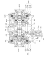
- FIG. 2 is a cross-sectional configuration diagram of the power transmission system of the bulldozer 1.
- FIG. 3 is a schematic system configuration diagram of the power transmission system of the bulldozer 1.
- the bulldozer 1 includes left and right traveling devices 4L and 4R having left and right sprockets 2L and 2R and left and right tracks 3L and 3R, a blade 5 provided at the front of the vehicle, and a ripper device 6 provided at the rear of the vehicle. Be prepared.
- the bulldozer 1 can perform work such as soil pushing by the blade 5 and work such as crushing and excavation by the ripper device 6.
- the bulldozer 1 includes an engine 10, a power transmission device 20, left and right planetary gear mechanisms 30L and 30R, left and right steering clutches 40L and 40R, left and right steering brakes 50L and 50R, and left and right output shafts 60L and 60R. It has left and right final deceleration devices 70L and 70R.
- the power transmission device 20 transmits the power from the engine 10 to the left and right planetary gear mechanisms 30L and 30R.
- the power transmission device 20 includes a power take-off device (power take-off) 21, a torque converter 22, a transmission 23, a pinion 24, a bevel gear 25, and an input shaft 26.
- the power extraction device 21 transmits the power from the engine 10 to the torque converter 22.
- the torque converter 22 transmits the power of the engine 10 transmitted from the power extraction device 21 to the transmission 23 via a fluid.
- the transmission 23 shifts the rotational motion transmitted from the torque converter 22.
- the transmission 23 can be switched between forward and reverse.
- the transmission 23 is connected to the pinion 24.
- the power from the transmission 23 is transmitted to the input shaft 26 via the pinion 24 and the bevel gear 25.
- the left and right planetary gear mechanisms 30L and 30R are arranged between the input shaft 26 and the left and right output shafts 60L and 60R.
- the left and right planetary gear mechanisms 30L and 30R have left and right ring gears 31L and 31R, left and right planetary gears 32L and 32R, left and right sun gears 33L and 33R, and left and right carriers 34L and 34R.
- the left and right ring gears 31L and 31R are connected to the input shaft 26.
- the left and right planetary gears 32L and 32R are arranged inside the left and right ring gears 31L and 31R in the radial direction perpendicular to the axis of the input shaft 26.
- the left and right planetary gears 32L and 32R mesh with the left and right ring gears 31L and 31R and the left and right sun gears 33L and 33R.
- the left and right sun gears 33L and 33R are rotatably attached to the input shaft 26.
- the left and right sun gears 33L and 33R are arranged inside the left and right planetary gears 32L and 32R in the radial direction.
- the left and right sun gears 33L and 33R are connected to the left and right steering clutches 40L and 40R.
- the left and right carriers 34L and 34R are connected to the left and right planetary gears 32L and 32R and the left and right output shafts 60L and 60R.
- the left and right steering clutches 40L and 40R are wet multi-plate clutches that can be engaged with or released from the left and right sun gears 33L and 33R.
- the left and right steering clutches 40L and 40R switch between transmission and interruption of rotation from the input shaft 26 by the left and right planetary gear mechanisms 30L and 30R to the left and right output shafts 60L and 60R.
- the left steering clutch 40L when the left steering clutch 40L is engaged and the left sun gear 33L is directly connected to the first clutch gear 91, the first clutch gear 91 is non-rotatable (described later), so that the left sun gear 33L is also non-rotatable. .. Then, the rotation of the input shaft 26 is transmitted to the left output shaft 60L via the left ring gear 31L, the left planetary gear 32L, and the left carrier 34L. Further, when the left steering clutch 40L is released and the left sun gear 33L is in a free rotation state, the rotation from the input shaft 26 to the left output shaft 60L is cut off. Similarly, the right steering clutch 40R also switches between transmission and disconnection of rotation from the input shaft 26 to the right output shaft 60R according to its engagement and disengagement.
- the first clutch gear 91 is attached to the left steering clutch 40L.
- the first clutch gear 91 is fixed so as not to rotate.
- the first clutch gear 91 is directly connected to the idler gear 93.
- the second clutch gear 92 is attached to the right steering clutch 40R.
- the second clutch gear 92 is fixed so as not to rotate.
- the second clutch gear 92 is indirectly connected to the idler gear 93 via the first transfer gear 95, the auxiliary shaft 96, and the second transfer gear 97.
- the idler gear 93 is connected to the pinion gear 94.
- a pinion shaft 94a is connected to the pinion gear 94.
- the pinion shaft 94a is non-rotatably fixed by the fixing member 98.
- the pinion gear 94 is fixed so as not to be rotatable by fixing the pinion shaft 94a so as not to be rotatable. Then, by fixing the pinion gear 94 so as not to rotate, each of the first clutch gear 91 and the second clutch gear 92 is fixed so as not to rotate.
- the fixing member 98 is detachably fixed to a housing (not shown).
- the fixing member 98 is also removable from the pinion gear 94. As a result, the fixing of the pinion gear 94 by the fixing member 98 is released.
- the turning motor 99 can be attached to the pinion shaft 94a as shown in FIG.
- the turning motor 99 is a hydraulic pump driven by the power of the engine 10 transmitted from the power extraction device 21.
- the gear 97 functions as a transmission unit that transmits the rotational power of the turning motor 99 to the left and right sun gears 33L and 33R.
- the left and right steering brakes 50L and 50R brake the rotation of the left and right output shafts 60L and 60R.
- the left and right steering brakes 50L and 50R are wet multi-plate clutches that can be engaged with or released from the left and right output shafts 60L and 60R.
- the bulldozer 1 includes a left planetary gear mechanism 30L, a left steering clutch 40L, and a first clutch gear 91.
- the left planetary gear mechanism 30L is arranged between the input shaft 26 and the left output shaft 60L.
- the left steering clutch 40L switches between transmission and interruption of rotational power from the input shaft 26 to the left output shaft 60L by the left planetary gear mechanism 30L.
- the first clutch gear 91 is attached to the left steering clutch 40L.
- the left steering clutch 40L can be engaged with or disengaged from the left sun gear 33L.
- the first clutch gear 91 is fixed so as not to rotate.
- the left steering clutch 40L is attached to the left sun gear 33L in this way, the torque passing through the left steering clutch 40L can be reduced. Therefore, since it is not necessary to excessively increase the rigidity of the left steering clutch 40L, the left steering clutch 40L can be miniaturized. This effect can be similarly obtained with the right steering clutch 40R.
- the left sun gear 33L can be easily braked, and when the fixing of the first clutch gear 91 is released, the left steering clutch 40L is released. It can be easily modified to a configuration that can transmit rotational power to the left sun gear 33L via the clutch. This effect is also obtained by the second clutch gear 92.
- the pinion gear 94 is fixed to be non-rotatable by fixing the pinion shaft 94a so as not to be rotatable, but the fixing method of the pinion gear 94 is not limited to this.
- the teeth of the pinion gear 94 may be directly fixed.
- the first clutch gear 91 and the second clutch gear 92 are connected to the pinion gear 94 via the idler gear 93, but as shown in FIG. 5, the idler gear 93 can be omitted.
- the idler gear 93 is non-rotatably fixed by a plurality of idler gear bolts 100 as fixing members, but the number of idler gear bolts 100 is not particularly limited and may be one or more.
- the pinion gear 94 is fixed in a non-rotatable manner to fix the first clutch gear 91 and the second clutch gear 92 in a non-rotatable manner, but the present invention is not limited to this.
- the idler gear 93 is fixed to be non-rotatable instead of the pinion gear 94, so that the first clutch gear 91 and the second clutch gear 92 are fixed to be non-rotatable. Can be done.
- the idler gear bolt 100 shown in FIG. 5 can be used to fix the idler gear 93.
Abstract
According to the present invention, a bulldozer (1) comprises a left planetary gear mechanism (30L), a left steering clutch (40L), and a first clutch gear (91). The left planetary gear mechanism (30L) is disposed between an input shaft (26) and a left output shaft (60L). The left steering clutch (40L) switches the transmission and cutoff of rotary power from the input shaft (26) to the left output shaft (60L) by means of the left planetary gear mechanism (30L). The first clutch gear (91) is attached to the left steering clutch (40L). The left steering clutch (40L) can engage with or disengage from a left sun gear (33L). The first clutch gear (91) is fixed in a non-rotatable manner.
Description
本開示は、履帯式作業機械に関する。
This disclosure relates to track-type work machines.
従来、履帯式作業機械(例えば、ブルドーザなど)は、左右の駆動輪に連結された左右の出力軸を制動する左右のステアリングブレーキと、左右の出力軸の間に配置される入力軸に取り付けられ、入力軸から出力軸へ回転動力を伝達又は遮断するステアリングクラッチとが設けられている(例えば、特許文献1参照)。
Conventionally, a belt-type work machine (for example, a bulldozer) is attached to a left and right steering brake that brakes the left and right output shafts connected to the left and right drive wheels, and an input shaft arranged between the left and right output shafts. , A steering clutch that transmits or cuts off rotational power from the input shaft to the output shaft is provided (see, for example, Patent Document 1).
履帯式作業機械は、ステアリングクラッチ及びステアリングブレーキを油圧制御することによって、左右に旋回することができる。
The track-type work machine can turn left and right by hydraulically controlling the steering clutch and steering brake.
しかしながら、特許文献1に記載の履帯式作業機械では、ステアリングクラッチが入力軸に直接的に取り付けられているため、ステアリングクラッチを大きなトルクが通過する。そのため、ステアリングクラッチに高い剛性を持たせる必要があり、ステアリングクラッチを小型化することができない。
However, in the track-type work machine described in Patent Document 1, since the steering clutch is directly attached to the input shaft, a large torque passes through the steering clutch. Therefore, it is necessary to give the steering clutch high rigidity, and the steering clutch cannot be miniaturized.
本開示の課題は、ステアリングクラッチを小型化可能な履帯式作業機械を提供することである。
The subject of this disclosure is to provide a track-type work machine capable of downsizing the steering clutch.
本開示の一側面に係る履帯式作業機械は、遊星歯車機構と、ステアリングクラッチと、クラッチギアとを備える。遊星歯車機構は、入力軸と出力軸との間に配置される。ステアリングクラッチは、遊星歯車機構による入力軸から出力軸への回転動力の伝達及び遮断を切り替える。クラッチギアは、ステアリングクラッチに取り付けられる。遊星歯車機構は、入力軸に連結されるリングギアと、入力軸に対して回転自在に取り付けられるサンギアと、リングギア及びサンギアの間に配置されるプラネタリギアと、プラネタリギアと出力軸とに連結されるキャリアとを有する。ステアリングクラッチは、サンギアに対して係合又は開放可能である。クラッチギアは、回転不能に固定されている。
The track-type work machine according to one aspect of the present disclosure includes a planetary gear mechanism, a steering clutch, and a clutch gear. The planetary gear mechanism is arranged between the input shaft and the output shaft. The steering clutch switches between transmission and disconnection of rotational power from the input shaft to the output shaft by the planetary gear mechanism. The clutch gear is attached to the steering clutch. The planetary gear mechanism is connected to a ring gear connected to an input shaft, a sun gear rotatably attached to the input shaft, a planetary gear arranged between the ring gear and the sun gear, and a planetary gear and an output shaft. Have a carrier to be. The steering clutch can be engaged or disengaged with respect to the sun gear. The clutch gear is fixed so that it cannot rotate.
本開示に係る履帯式作業機械によれば、ステアリングクラッチを小型化することができる。
According to the track-type work machine according to the present disclosure, the steering clutch can be miniaturized.
(ブルドーザ1の構成)
図1は、履帯式作業機械の一例であるブルドーザ1の斜視図である。図2は、ブルドーザ1の動力伝達系統の断面構成図である。図3は、ブルドーザ1の動力伝達系統の概略システム構成図である。 (Structure of bulldozer 1)
FIG. 1 is a perspective view of a bulldozer 1, which is an example of a track-type work machine. FIG. 2 is a cross-sectional configuration diagram of the power transmission system of the bulldozer 1. FIG. 3 is a schematic system configuration diagram of the power transmission system of the bulldozer 1.
ブルドーザ1は、左右のスプロケット2L,2R及び左右の履帯3L,3Rを有する左右の走行装置4L,4Rと、車両前部に設けられたブレード5と、車両後部に設けられたリッパ装置6とを備える。
The bulldozer 1 includes left and right traveling devices 4L and 4R having left and right sprockets 2L and 2R and left and right tracks 3L and 3R, a blade 5 provided at the front of the vehicle, and a ripper device 6 provided at the rear of the vehicle. Be prepared.
ブルドーザ1は、ブレード5による土押し等の作業や、リッパ装置6による破砕及び掘削等の作業を行うことができる。
The bulldozer 1 can perform work such as soil pushing by the blade 5 and work such as crushing and excavation by the ripper device 6.
ブルドーザ1は、エンジン10と、動力伝達装置20と、左右の遊星歯車機構30L,30Rと、左右のステアリングクラッチ40L,40Rと、左右のステアリングブレーキ50L,50Rと、左右の出力軸60L,60Rと、左右の終減速装置70L,70Rとを有する。
The bulldozer 1 includes an engine 10, a power transmission device 20, left and right planetary gear mechanisms 30L and 30R, left and right steering clutches 40L and 40R, left and right steering brakes 50L and 50R, and left and right output shafts 60L and 60R. It has left and right final deceleration devices 70L and 70R.
動力伝達装置20は、エンジン10からの動力を左右の遊星歯車機構30L,30Rに伝達する。動力伝達装置20は、動力取出装置(パワーテイクオフ)21と、トルクコンバータ22と、トランスミッション23と、ピニオン24と、ベベルギア25と、入力軸26とを含む。
The power transmission device 20 transmits the power from the engine 10 to the left and right planetary gear mechanisms 30L and 30R. The power transmission device 20 includes a power take-off device (power take-off) 21, a torque converter 22, a transmission 23, a pinion 24, a bevel gear 25, and an input shaft 26.
動力取出装置21は、エンジン10からの動力をトルクコンバータ22に伝達する。トルクコンバータ22は、動力取出装置21から伝達されるエンジン10の動力を、流体を介してトランスミッション23に伝達する。トランスミッション23は、トルクコンバータ22から伝達される回転運動を変速する。トランスミッション23は、前進と後進に切り替え可能である。トランスミッション23は、ピニオン24に連結される。トランスミッション23からの動力は、ピニオン24及びベベルギア25を介して、入力軸26に伝達される。
The power extraction device 21 transmits the power from the engine 10 to the torque converter 22. The torque converter 22 transmits the power of the engine 10 transmitted from the power extraction device 21 to the transmission 23 via a fluid. The transmission 23 shifts the rotational motion transmitted from the torque converter 22. The transmission 23 can be switched between forward and reverse. The transmission 23 is connected to the pinion 24. The power from the transmission 23 is transmitted to the input shaft 26 via the pinion 24 and the bevel gear 25.
左右の遊星歯車機構30L,30Rは、入力軸26と左右の出力軸60L,60Rとの間に配置される。左右の遊星歯車機構30L,30Rは、左右のリングギア31L,31R、左右のプラネタリギア32L,32R、左右のサンギア33L,33R及び左右のキャリア34L,34Rを有する。
The left and right planetary gear mechanisms 30L and 30R are arranged between the input shaft 26 and the left and right output shafts 60L and 60R. The left and right planetary gear mechanisms 30L and 30R have left and right ring gears 31L and 31R, left and right planetary gears 32L and 32R, left and right sun gears 33L and 33R, and left and right carriers 34L and 34R.
左右のリングギア31L,31Rは、入力軸26に連結される。左右のプラネタリギア32L,32Rは、入力軸26の軸心に垂直な径方向において、左右のリングギア31L,31Rの内側に配置される。左右のプラネタリギア32L,32Rは、左右のリングギア31L,31Rと左右のサンギア33L,33Rとに噛み合っている。左右のサンギア33L,33Rは、入力軸26に対して回転自在に取り付けられる。左右のサンギア33L,33Rは、径方向において、左右のプラネタリギア32L,32Rの内側に配置される。左右のサンギア33L,33Rは、左右のステアリングクラッチ40L,40Rに連結される。左右のキャリア34L,34Rは、左右のプラネタリギア32L,32Rと左右の出力軸60L,60Rとに連結される。
The left and right ring gears 31L and 31R are connected to the input shaft 26. The left and right planetary gears 32L and 32R are arranged inside the left and right ring gears 31L and 31R in the radial direction perpendicular to the axis of the input shaft 26. The left and right planetary gears 32L and 32R mesh with the left and right ring gears 31L and 31R and the left and right sun gears 33L and 33R. The left and right sun gears 33L and 33R are rotatably attached to the input shaft 26. The left and right sun gears 33L and 33R are arranged inside the left and right planetary gears 32L and 32R in the radial direction. The left and right sun gears 33L and 33R are connected to the left and right steering clutches 40L and 40R. The left and right carriers 34L and 34R are connected to the left and right planetary gears 32L and 32R and the left and right output shafts 60L and 60R.
左右のステアリングクラッチ40L,40Rは、左右のサンギア33L,33Rに対して係合又は開放可能な湿式多板式クラッチである。左右のステアリングクラッチ40L,40Rは、左右の遊星歯車機構30L,30Rによる入力軸26から左右の出力軸60L,60Rへの回転の伝達及び遮断を切り替える。
The left and right steering clutches 40L and 40R are wet multi-plate clutches that can be engaged with or released from the left and right sun gears 33L and 33R. The left and right steering clutches 40L and 40R switch between transmission and interruption of rotation from the input shaft 26 by the left and right planetary gear mechanisms 30L and 30R to the left and right output shafts 60L and 60R.
具体的には、左ステアリングクラッチ40Lが係合されて左サンギア33Lが第1クラッチギア91と直結すると、第1クラッチギア91は回転不能(後述)であるため、左サンギア33Lも回転不能になる。すると、入力軸26の回転は、左リングギア31L、左プラネタリギア32L及び左キャリア34Lを介して左出力軸60Lに伝達される。また、左ステアリングクラッチ40Lが開放されて左サンギア33Lが自由回転状態になると、入力軸26から左出力軸60Lへの回転は遮断される。同様に、右ステアリングクラッチ40Rも、その係合及び開放に応じて、入力軸26から右出力軸60Rへの回転の伝達及び遮断を切り替える。
Specifically, when the left steering clutch 40L is engaged and the left sun gear 33L is directly connected to the first clutch gear 91, the first clutch gear 91 is non-rotatable (described later), so that the left sun gear 33L is also non-rotatable. .. Then, the rotation of the input shaft 26 is transmitted to the left output shaft 60L via the left ring gear 31L, the left planetary gear 32L, and the left carrier 34L. Further, when the left steering clutch 40L is released and the left sun gear 33L is in a free rotation state, the rotation from the input shaft 26 to the left output shaft 60L is cut off. Similarly, the right steering clutch 40R also switches between transmission and disconnection of rotation from the input shaft 26 to the right output shaft 60R according to its engagement and disengagement.
ここで、左ステアリングクラッチ40Lには、第1クラッチギア91が取り付けられている。第1クラッチギア91は、回転不能に固定されている。第1クラッチギア91は、アイドラギア93と直接的に連結される。
Here, the first clutch gear 91 is attached to the left steering clutch 40L. The first clutch gear 91 is fixed so as not to rotate. The first clutch gear 91 is directly connected to the idler gear 93.
また、右ステアリングクラッチ40Rには、第2クラッチギア92が取り付けられている。第2クラッチギア92は、回転不能に固定されている。第2クラッチギア92は、第1トランスファギア95、副軸96及び第2トランスファギア97を介して、アイドラギア93と間接的に連結される。
Further, the second clutch gear 92 is attached to the right steering clutch 40R. The second clutch gear 92 is fixed so as not to rotate. The second clutch gear 92 is indirectly connected to the idler gear 93 via the first transfer gear 95, the auxiliary shaft 96, and the second transfer gear 97.
アイドラギア93は、ピニオンギア94に連結される。ピニオンギア94には、ピニオン軸94aが連結される。ピニオン軸94aは、固定部材98によって回転不能に固定される。
The idler gear 93 is connected to the pinion gear 94. A pinion shaft 94a is connected to the pinion gear 94. The pinion shaft 94a is non-rotatably fixed by the fixing member 98.
このように、本実施形態では、ピニオン軸94aを回転不能に固定することによって、ピニオンギア94が回転不能に固定されている。そして、ピニオンギア94を回転不能に固定することによって、第1クラッチギア91及び第2クラッチギア92それぞれが回転不能に固定されている。
As described above, in the present embodiment, the pinion gear 94 is fixed so as not to be rotatable by fixing the pinion shaft 94a so as not to be rotatable. Then, by fixing the pinion gear 94 so as not to rotate, each of the first clutch gear 91 and the second clutch gear 92 is fixed so as not to rotate.
従って、左右のステアリングクラッチ40L,40Rから左右のサンギア33L,33Rに回転動力が加えられることはない。よって、図3に示す構成において、第1クラッチギア91、第2クラッチギア92、アイドラギア93、ピニオンギア94、第1トランスファギア95、副軸96及び第2トランスファギア97は、左右のステアリングクラッチ40L,40Rが係合された場合に左右のサンギア33L,33Rを制動(固定)する機能のみを有している。
Therefore, rotational power is not applied from the left and right steering clutches 40L and 40R to the left and right sun gears 33L and 33R. Therefore, in the configuration shown in FIG. 3, the first clutch gear 91, the second clutch gear 92, the idler gear 93, the pinion gear 94, the first transfer gear 95, the layshaft 96, and the second transfer gear 97 are the left and right steering clutches 40L. , 40R has only the function of braking (fixing) the left and right sun gears 33L and 33R when engaged.
ここで、固定部材98は、図示しないハウジングに着脱可能に固定されている。固定部材98をハウジングから取り外した場合、固定部材98は、ピニオンギア94からも取り外し可能である。これにより、固定部材98によるピニオンギア94の固定は解除される。
Here, the fixing member 98 is detachably fixed to a housing (not shown). When the fixing member 98 is removed from the housing, the fixing member 98 is also removable from the pinion gear 94. As a result, the fixing of the pinion gear 94 by the fixing member 98 is released.
固定部材98によるピニオンギア94の固定を解除した場合、図4に示すように、ピニオン軸94aには、旋回用モータ99を取り付け可能である。本実施形態において、旋回用モータ99は、動力取出装置21から伝達されるエンジン10の動力によって駆動される油圧ポンプである。
When the pinion gear 94 is released from the fixing member 98, the turning motor 99 can be attached to the pinion shaft 94a as shown in FIG. In the present embodiment, the turning motor 99 is a hydraulic pump driven by the power of the engine 10 transmitted from the power extraction device 21.
このように、ピニオン軸94aの固定が解除されると、第1クラッチギア91及び第2クラッチギア92は回転可能となり、左右のステアリングクラッチ40L,40Rを介して旋回用モータ99の回転動力を左右のサンギア33L,33Rに加えることができる。
In this way, when the pinion shaft 94a is released from being fixed, the first clutch gear 91 and the second clutch gear 92 become rotatable, and the rotational power of the turning motor 99 is left and right via the left and right steering clutches 40L and 40R. It can be added to the Sun Gear 33L and 33R.
具体的には、左右のステアリングクラッチ40L,40Rが係合され、かつ、モータの回転動力が左右のステアリングクラッチ40L,40Rを介して左右のサンギア33L,33Rに伝達されると、左右のサンギア33L,33Rが同じ回転数で逆回転する。これによって、左右の出力軸60L,60Rに回転数差が生じて、ブルドーザ1は左右に緩旋回することができる。
Specifically, when the left and right steering clutches 40L and 40R are engaged and the rotational power of the motor is transmitted to the left and right sun gears 33L and 33R via the left and right steering clutches 40L and 40R, the left and right sun gears 33L , 33R reversely rotate at the same rotation speed. As a result, a difference in rotation speed occurs between the left and right output shafts 60L and 60R, and the bulldozer 1 can slowly turn left and right.
以上の通り、ピニオン軸94aに旋回用モータ99が取り付けられた場合、第1クラッチギア91、第2クラッチギア92、アイドラギア93、ピニオンギア94、第1トランスファギア95、副軸96及び第2トランスファギア97は、旋回用モータ99の回転動力を左右のサンギア33L,33Rに伝達する伝達部として機能する。
As described above, when the turning motor 99 is attached to the pinion shaft 94a, the first clutch gear 91, the second clutch gear 92, the idler gear 93, the pinion gear 94, the first transfer gear 95, the auxiliary shaft 96 and the second transfer are used. The gear 97 functions as a transmission unit that transmits the rotational power of the turning motor 99 to the left and right sun gears 33L and 33R.
左右のステアリングブレーキ50L,50Rは、左右の出力軸60L,60Rの回転を制動する。左右のステアリングブレーキ50L,50Rは、左右の出力軸60L,60Rに対して係合又は開放可能な湿式多板式クラッチである。
The left and right steering brakes 50L and 50R brake the rotation of the left and right output shafts 60L and 60R. The left and right steering brakes 50L and 50R are wet multi-plate clutches that can be engaged with or released from the left and right output shafts 60L and 60R.
左ステアリングブレーキ50Lが係合されると、左出力軸60Lの回転が制動される。その結果、左スプロケット2Lに連結された左終減速装置70Lの回転が低減される。右ステアリングブレーキ50Rが係合されると、右出力軸60Rの回転が制動される。その結果、右スプロケット2Rに連結された右終減速装置70Rの回転が低減される。
When the left steering brake 50L is engaged, the rotation of the left output shaft 60L is damped. As a result, the rotation of the left final speed reducer 70L connected to the left sprocket 2L is reduced. When the right steering brake 50R is engaged, the rotation of the right output shaft 60R is damped. As a result, the rotation of the right final speed reducer 70R connected to the right sprocket 2R is reduced.
(特徴)
ブルドーザ1は、左遊星歯車機構30Lと、左ステアリングクラッチ40Lと、第1クラッチギア91とを備える。左遊星歯車機構30Lは、入力軸26と左出力軸60Lとの間に配置される。左ステアリングクラッチ40Lは、左遊星歯車機構30Lによる入力軸26から左出力軸60Lへの回転動力の伝達及び遮断を切り替える。第1クラッチギア91は、左ステアリングクラッチ40Lに取り付けられる。左ステアリングクラッチ40Lは、左サンギア33Lに対して係合又は開放可能である。第1クラッチギア91は、回転不能に固定されている。 (Features)
The bulldozer 1 includes a leftplanetary gear mechanism 30L, a left steering clutch 40L, and a first clutch gear 91. The left planetary gear mechanism 30L is arranged between the input shaft 26 and the left output shaft 60L. The left steering clutch 40L switches between transmission and interruption of rotational power from the input shaft 26 to the left output shaft 60L by the left planetary gear mechanism 30L. The first clutch gear 91 is attached to the left steering clutch 40L. The left steering clutch 40L can be engaged with or disengaged from the left sun gear 33L. The first clutch gear 91 is fixed so as not to rotate.
ブルドーザ1は、左遊星歯車機構30Lと、左ステアリングクラッチ40Lと、第1クラッチギア91とを備える。左遊星歯車機構30Lは、入力軸26と左出力軸60Lとの間に配置される。左ステアリングクラッチ40Lは、左遊星歯車機構30Lによる入力軸26から左出力軸60Lへの回転動力の伝達及び遮断を切り替える。第1クラッチギア91は、左ステアリングクラッチ40Lに取り付けられる。左ステアリングクラッチ40Lは、左サンギア33Lに対して係合又は開放可能である。第1クラッチギア91は、回転不能に固定されている。 (Features)
The bulldozer 1 includes a left
このように、左ステアリングクラッチ40Lが左サンギア33Lに取り付けられているため、左ステアリングクラッチ40Lを通過するトルクを小さくすることができる。従って、左ステアリングクラッチ40Lの剛性を過剰に高める必要がないため、左ステアリングクラッチ40Lを小型化することができる。本効果は、右ステアリングクラッチ40Rにおいても同様に得られる。
Since the left steering clutch 40L is attached to the left sun gear 33L in this way, the torque passing through the left steering clutch 40L can be reduced. Therefore, since it is not necessary to excessively increase the rigidity of the left steering clutch 40L, the left steering clutch 40L can be miniaturized. This effect can be similarly obtained with the right steering clutch 40R.
また、第1クラッチギア91が回転不能に固定されているため、左サンギア33Lを簡便に制動することができるとともに、第1クラッチギア91の固定が解除された場合には、左ステアリングクラッチ40Lを介して左サンギア33Lに回転動力を伝達可能な構成に簡便に改造できる。本効果は、第2クラッチギア92によっても同様に得られる。
Further, since the first clutch gear 91 is fixed so as not to rotate, the left sun gear 33L can be easily braked, and when the fixing of the first clutch gear 91 is released, the left steering clutch 40L is released. It can be easily modified to a configuration that can transmit rotational power to the left sun gear 33L via the clutch. This effect is also obtained by the second clutch gear 92.
(実施形態の変形例)
本発明は以上のような実施形態に限定されるものではなく、本発明の範囲を逸脱することなく種々の変形又は修正が可能である。 (Modified example of the embodiment)
The present invention is not limited to the above embodiments, and various modifications or modifications can be made without departing from the scope of the present invention.
本発明は以上のような実施形態に限定されるものではなく、本発明の範囲を逸脱することなく種々の変形又は修正が可能である。 (Modified example of the embodiment)
The present invention is not limited to the above embodiments, and various modifications or modifications can be made without departing from the scope of the present invention.
(変形例1)
上記実施形態では、ピニオン軸94aを回転不能に固定することによって、ピニオンギア94が回転不能に固定されることとしたが、ピニオンギア94の固定方法はこれに限られない。例えば、ピニオンギア94の歯を直接的に固定してもよい。 (Modification 1)
In the above embodiment, thepinion gear 94 is fixed to be non-rotatable by fixing the pinion shaft 94a so as not to be rotatable, but the fixing method of the pinion gear 94 is not limited to this. For example, the teeth of the pinion gear 94 may be directly fixed.
上記実施形態では、ピニオン軸94aを回転不能に固定することによって、ピニオンギア94が回転不能に固定されることとしたが、ピニオンギア94の固定方法はこれに限られない。例えば、ピニオンギア94の歯を直接的に固定してもよい。 (Modification 1)
In the above embodiment, the
(変形例2)
上記実施形態では、第1クラッチギア91及び第2クラッチギア92は、アイドラギア93を介してピニオンギア94に連結されることとしたが、図5に示すように、アイドラギア93は省略可能である。この場合、ピニオンギア94の代わりにアイドラギア93を回転不能に固定することによって、第1クラッチギア91及び第2クラッチギア92それぞれを回転不能に固定することができる。図5に示す例では、固定部材としての複数のアイドラギアボルト100によってアイドラギア93が回転不能に固定されているが、アイドラギアボルト100の本数は特に限られず、1本以上であればよい。 (Modification 2)
In the above embodiment, the firstclutch gear 91 and the second clutch gear 92 are connected to the pinion gear 94 via the idler gear 93, but as shown in FIG. 5, the idler gear 93 can be omitted. In this case, by fixing the idler gear 93 non-rotatably instead of the pinion gear 94, each of the first clutch gear 91 and the second clutch gear 92 can be fixed non-rotatably. In the example shown in FIG. 5, the idler gear 93 is non-rotatably fixed by a plurality of idler gear bolts 100 as fixing members, but the number of idler gear bolts 100 is not particularly limited and may be one or more.
上記実施形態では、第1クラッチギア91及び第2クラッチギア92は、アイドラギア93を介してピニオンギア94に連結されることとしたが、図5に示すように、アイドラギア93は省略可能である。この場合、ピニオンギア94の代わりにアイドラギア93を回転不能に固定することによって、第1クラッチギア91及び第2クラッチギア92それぞれを回転不能に固定することができる。図5に示す例では、固定部材としての複数のアイドラギアボルト100によってアイドラギア93が回転不能に固定されているが、アイドラギアボルト100の本数は特に限られず、1本以上であればよい。 (Modification 2)
In the above embodiment, the first
(変形例3)
上記実施形態では、ピニオンギア94を回転不能に固定することによって、第1クラッチギア91及び第2クラッチギア92それぞれを回転不能に固定することとしたが、これに限られない。例えば、ピニオンギア94が存在する場合であっても、ピニオンギア94の代わりにアイドラギア93を回転不能に固定することによって、第1クラッチギア91及び第2クラッチギア92それぞれを回転不能に固定することができる。この場合、アイドラギア93の固定には、図5に示したアイドラギアボルト100を用いることができる。 (Modification 3)
In the above embodiment, thepinion gear 94 is fixed in a non-rotatable manner to fix the first clutch gear 91 and the second clutch gear 92 in a non-rotatable manner, but the present invention is not limited to this. For example, even when the pinion gear 94 is present, the idler gear 93 is fixed to be non-rotatable instead of the pinion gear 94, so that the first clutch gear 91 and the second clutch gear 92 are fixed to be non-rotatable. Can be done. In this case, the idler gear bolt 100 shown in FIG. 5 can be used to fix the idler gear 93.
上記実施形態では、ピニオンギア94を回転不能に固定することによって、第1クラッチギア91及び第2クラッチギア92それぞれを回転不能に固定することとしたが、これに限られない。例えば、ピニオンギア94が存在する場合であっても、ピニオンギア94の代わりにアイドラギア93を回転不能に固定することによって、第1クラッチギア91及び第2クラッチギア92それぞれを回転不能に固定することができる。この場合、アイドラギア93の固定には、図5に示したアイドラギアボルト100を用いることができる。 (Modification 3)
In the above embodiment, the
1 ブルドーザ
10 エンジン
20 動力伝達装置
26 入力軸
30L,30R 左右の遊星歯車機構
31L,31R 左右のリングギア
32L,32R 左右のプラネタリギア
33L,33R 左右のサンギア
34L,34R 左右のキャリア
40L,40R 左右のステアリングクラッチ
50L,50R 左右のステアリングブレーキ
60L,60R 左右の出力軸
70L,70R 左右の終減速装置
91 第1クラッチギア
92 第2クラッチギア
93 アイドラギア
94 ピニオンギア
95 第1トランスファギア
96 副軸
97 第2トランスファギア
98 固定部材
99 旋回用モータ 1Bulldozer 10 Engine 20 Power transmission device 26 Input shaft 30L, 30R Left and right planetary gear mechanism 31L, 31R Left and right ring gear 32L, 32R Left and right planetary gear 33L, 33R Left and right sun gear 34L, 34R Left and right carriers 40L, 40R Left and right Steering clutch 50L, 50R Left and right steering brakes 60L, 60R Left and right output shafts 70L, 70R Left and right final reduction gear 91 1st clutch gear 92 2nd clutch gear 93 Idler gear 94 Pinion gear 95 1st transfer gear 96 Sub shaft 97 2nd Transfer gear 98 Fixing member 99 Turning motor
10 エンジン
20 動力伝達装置
26 入力軸
30L,30R 左右の遊星歯車機構
31L,31R 左右のリングギア
32L,32R 左右のプラネタリギア
33L,33R 左右のサンギア
34L,34R 左右のキャリア
40L,40R 左右のステアリングクラッチ
50L,50R 左右のステアリングブレーキ
60L,60R 左右の出力軸
70L,70R 左右の終減速装置
91 第1クラッチギア
92 第2クラッチギア
93 アイドラギア
94 ピニオンギア
95 第1トランスファギア
96 副軸
97 第2トランスファギア
98 固定部材
99 旋回用モータ 1
Claims (5)
- 入力軸と出力軸との間に配置される遊星歯車機構と、
前記遊星歯車機構による前記入力軸から前記出力軸への回転動力の伝達及び遮断を切り替えるステアリングクラッチと、
前記ステアリングクラッチに取り付けられるクラッチギアと、
を備え、
前記遊星歯車機構は、
前記入力軸に連結されるリングギアと、
前記入力軸に対して回転自在に取り付けられるサンギアと、
前記リングギア及び前記サンギアの間に配置されるプラネタリギアと、
前記プラネタリギアと前記出力軸とに連結されるキャリアと、
を有し、
前記ステアリングクラッチは、前記サンギアに対して係合又は開放可能であり、
前記クラッチギアは、回転不能に固定されている、
履帯式作業機械。 A planetary gear mechanism located between the input shaft and the output shaft,
A steering clutch that switches the transmission and disconnection of rotational power from the input shaft to the output shaft by the planetary gear mechanism, and
The clutch gear attached to the steering clutch and
Equipped with
The planetary gear mechanism
The ring gear connected to the input shaft and
A sun gear that can be rotatably attached to the input shaft,
A planetary gear arranged between the ring gear and the sun gear, and
A carrier connected to the planetary gear and the output shaft,
Have,
The steering clutch can be engaged or disengaged with respect to the sun gear.
The clutch gear is fixed so as not to rotate.
Track type work machine. - 前記クラッチギアと連結されるアイドラギアと、
前記アイドラギアと連結されるピニオンギアと、
を備え、
前記アイドラギア及び前記ピニオンギアの少なくとも一方が回転不能に固定されることによって、前記クラッチギアが回転不能に固定されている、
請求項1に記載の履帯式作業機械。 The idler gear connected to the clutch gear and
The pinion gear connected to the idler gear and
Equipped with
The clutch gear is fixed to be non-rotatable by fixing at least one of the idler gear and the pinion gear to be non-rotatable.
The track-type work machine according to claim 1. - 前記クラッチギアと連結されるピニオンギアを備え、
前記ピニオンギアが回転不能に固定されることによって、前記クラッチギアが回転不能に固定されている、
請求項1に記載の履帯式作業機械。 It has a pinion gear that is connected to the clutch gear.
By fixing the pinion gear so that it cannot rotate, the clutch gear is fixed so that it cannot rotate.
The track-type work machine according to claim 1. - 前記ピニオンギアに連結されるピニオン軸を備え、
前記ピニオン軸が回転不能に固定されることによって、前記クラッチギアが回転不能に固定されている、
請求項2又は3に記載の履帯式作業機械。 A pinion shaft connected to the pinion gear is provided.
By fixing the pinion shaft so that it cannot rotate, the clutch gear is fixed so that it cannot rotate.
The track-type work machine according to claim 2 or 3. - 前記ピニオン軸の固定を取り外した場合、前記ピニオン軸には、旋回用モータを取り付け可能である、
請求項4に記載の履帯式作業機械。 When the fixing of the pinion shaft is removed, a turning motor can be attached to the pinion shaft.
The track-type work machine according to claim 4.
Priority Applications (3)
| Application Number | Priority Date | Filing Date | Title |
|---|---|---|---|
| CN202180030294.0A CN115427290A (en) | 2020-07-30 | 2021-06-15 | Crawler-type working machine |
| US17/918,195 US20230192187A1 (en) | 2020-07-30 | 2021-06-15 | Crawler-type work machine |
| JP2022540055A JPWO2022024571A1 (en) | 2020-07-30 | 2021-06-15 |
Applications Claiming Priority (2)
| Application Number | Priority Date | Filing Date | Title |
|---|---|---|---|
| JP2020129003 | 2020-07-30 | ||
| JP2020-129003 | 2020-07-30 |
Publications (1)
| Publication Number | Publication Date |
|---|---|
| WO2022024571A1 true WO2022024571A1 (en) | 2022-02-03 |
Family
ID=80035425
Family Applications (1)
| Application Number | Title | Priority Date | Filing Date |
|---|---|---|---|
| PCT/JP2021/022721 WO2022024571A1 (en) | 2020-07-30 | 2021-06-15 | Crawler-type work machine |
Country Status (4)
| Country | Link |
|---|---|
| US (1) | US20230192187A1 (en) |
| JP (1) | JPWO2022024571A1 (en) |
| CN (1) | CN115427290A (en) |
| WO (1) | WO2022024571A1 (en) |
Citations (4)
| Publication number | Priority date | Publication date | Assignee | Title |
|---|---|---|---|---|
| JPS5292065A (en) * | 1976-01-29 | 1977-08-03 | Srm Hydromekanik Ab | Multiple step planetary toothed wheel transmission gear for use in automobiles |
| JPS5382145U (en) * | 1976-12-09 | 1978-07-07 | ||
| US5041064A (en) * | 1987-10-09 | 1991-08-20 | Zahnradfabrik Friedrichshafen Ag | Superimposed steering gear for tracklaying vehicles |
| US20170182884A1 (en) * | 2015-12-24 | 2017-06-29 | Hyundai Dymos Incorporated | Driving apparatus for rear wheel of environment-friendly vehicle |
-
2021
- 2021-06-15 JP JP2022540055A patent/JPWO2022024571A1/ja active Pending
- 2021-06-15 US US17/918,195 patent/US20230192187A1/en active Pending
- 2021-06-15 CN CN202180030294.0A patent/CN115427290A/en active Pending
- 2021-06-15 WO PCT/JP2021/022721 patent/WO2022024571A1/en active Application Filing
Patent Citations (4)
| Publication number | Priority date | Publication date | Assignee | Title |
|---|---|---|---|---|
| JPS5292065A (en) * | 1976-01-29 | 1977-08-03 | Srm Hydromekanik Ab | Multiple step planetary toothed wheel transmission gear for use in automobiles |
| JPS5382145U (en) * | 1976-12-09 | 1978-07-07 | ||
| US5041064A (en) * | 1987-10-09 | 1991-08-20 | Zahnradfabrik Friedrichshafen Ag | Superimposed steering gear for tracklaying vehicles |
| US20170182884A1 (en) * | 2015-12-24 | 2017-06-29 | Hyundai Dymos Incorporated | Driving apparatus for rear wheel of environment-friendly vehicle |
Also Published As
| Publication number | Publication date |
|---|---|
| US20230192187A1 (en) | 2023-06-22 |
| CN115427290A (en) | 2022-12-02 |
| JPWO2022024571A1 (en) | 2022-02-03 |
Similar Documents
| Publication | Publication Date | Title |
|---|---|---|
| KR100442475B1 (en) | Compact Transmission installed between bevel and differential gear | |
| JP4372072B2 (en) | Variable speed transmission | |
| WO2022158138A1 (en) | Crawler-type work machine | |
| JP2008089075A (en) | Driving force distributing device for vehicle | |
| WO2022024571A1 (en) | Crawler-type work machine | |
| WO2020050216A1 (en) | Tractor, travel transmission device for tractor, and tractor equipped with travel transmission device for tractor | |
| JP7028141B2 (en) | Transfer for four-wheel drive vehicles | |
| JP2008175294A (en) | Travel transmission device | |
| JP2003267079A (en) | Front wheel transmission device for working vehicle | |
| WO2022024573A1 (en) | Crawler work machine | |
| WO2022158179A1 (en) | Crawler-type work machine | |
| WO2022137833A1 (en) | Crawler-type work machine | |
| WO2022137836A1 (en) | Track-type work machine | |
| JP4362196B2 (en) | Tracked tractor | |
| WO2023149141A1 (en) | Crawler-type work machine | |
| JP2003083420A (en) | Machinery-hydraulic transmission of wheel type vehicle | |
| JP2009292210A (en) | Working vehicle | |
| JP7206077B2 (en) | Tractor travel transmission and tractor equipped with this tractor travel transmission | |
| JP2023118535A (en) | Work machine | |
| JP5037426B2 (en) | Work vehicle | |
| JP4551716B2 (en) | Power transmission mechanism | |
| WO2020178908A1 (en) | Power transmission mechanism and travel drive device for vehicle | |
| JP4551718B2 (en) | Power transmission mechanism | |
| KR20120079686A (en) | Transmission unit for agriculture machine | |
| JP2022175726A (en) | Vehicular four-wheel drive device |
Legal Events
| Date | Code | Title | Description |
|---|---|---|---|
| 121 | Ep: the epo has been informed by wipo that ep was designated in this application |
Ref document number: 21850042 Country of ref document: EP Kind code of ref document: A1 |
|
| ENP | Entry into the national phase |
Ref document number: 2022540055 Country of ref document: JP Kind code of ref document: A |
|
| NENP | Non-entry into the national phase |
Ref country code: DE |
|
| 122 | Ep: pct application non-entry in european phase |
Ref document number: 21850042 Country of ref document: EP Kind code of ref document: A1 |