WO2022019295A1 - ガスタービンプラント - Google Patents
ガスタービンプラント Download PDFInfo
- Publication number
- WO2022019295A1 WO2022019295A1 PCT/JP2021/027085 JP2021027085W WO2022019295A1 WO 2022019295 A1 WO2022019295 A1 WO 2022019295A1 JP 2021027085 W JP2021027085 W JP 2021027085W WO 2022019295 A1 WO2022019295 A1 WO 2022019295A1
- Authority
- WO
- WIPO (PCT)
- Prior art keywords
- exhaust gas
- gas
- heater
- turbine
- egr
- Prior art date
Links
- CURLTUGMZLYLDI-UHFFFAOYSA-N Carbon dioxide Chemical compound O=C=O CURLTUGMZLYLDI-UHFFFAOYSA-N 0.000 claims abstract description 62
- 238000010521 absorption reaction Methods 0.000 claims abstract description 42
- 238000011084 recovery Methods 0.000 claims abstract description 40
- 229910002092 carbon dioxide Inorganic materials 0.000 claims abstract description 31
- 239000001569 carbon dioxide Substances 0.000 claims abstract description 28
- XLYOFNOQVPJJNP-UHFFFAOYSA-N water Substances O XLYOFNOQVPJJNP-UHFFFAOYSA-N 0.000 claims abstract description 20
- 238000001816 cooling Methods 0.000 claims description 15
- 238000010438 heat treatment Methods 0.000 claims description 4
- 239000000284 extract Substances 0.000 claims description 3
- 239000007789 gas Substances 0.000 abstract description 235
- 239000002918 waste heat Substances 0.000 abstract 2
- 239000007788 liquid Substances 0.000 description 31
- 230000008929 regeneration Effects 0.000 description 16
- 238000011069 regeneration method Methods 0.000 description 16
- 239000000779 smoke Substances 0.000 description 14
- 229920006395 saturated elastomer Polymers 0.000 description 7
- 239000002250 absorbent Substances 0.000 description 6
- 230000002745 absorbent Effects 0.000 description 6
- 238000000034 method Methods 0.000 description 6
- 239000000203 mixture Substances 0.000 description 3
- 238000012986 modification Methods 0.000 description 3
- 230000004048 modification Effects 0.000 description 3
- MWUXSHHQAYIFBG-UHFFFAOYSA-N nitrogen oxide Inorganic materials O=[N] MWUXSHHQAYIFBG-UHFFFAOYSA-N 0.000 description 3
- HZAXFHJVJLSVMW-UHFFFAOYSA-N 2-Aminoethan-1-ol Chemical compound NCCO HZAXFHJVJLSVMW-UHFFFAOYSA-N 0.000 description 2
- GSEJCLTVZPLZKY-UHFFFAOYSA-N Triethanolamine Chemical compound OCCN(CCO)CCO GSEJCLTVZPLZKY-UHFFFAOYSA-N 0.000 description 2
- 150000001412 amines Chemical class 0.000 description 2
- 239000007864 aqueous solution Substances 0.000 description 2
- 238000009529 body temperature measurement Methods 0.000 description 2
- 239000000567 combustion gas Substances 0.000 description 2
- 230000006835 compression Effects 0.000 description 2
- 238000007906 compression Methods 0.000 description 2
- ZBCBWPMODOFKDW-UHFFFAOYSA-N diethanolamine Chemical compound OCCNCCO ZBCBWPMODOFKDW-UHFFFAOYSA-N 0.000 description 2
- LVTYICIALWPMFW-UHFFFAOYSA-N diisopropanolamine Chemical compound CC(O)CNCC(C)O LVTYICIALWPMFW-UHFFFAOYSA-N 0.000 description 2
- 229940043276 diisopropanolamine Drugs 0.000 description 2
- 238000000605 extraction Methods 0.000 description 2
- 239000000446 fuel Substances 0.000 description 2
- CRVGTESFCCXCTH-UHFFFAOYSA-N methyl diethanolamine Chemical compound OCCN(C)CCO CRVGTESFCCXCTH-UHFFFAOYSA-N 0.000 description 2
- 150000001413 amino acids Chemical class 0.000 description 1
- 230000015572 biosynthetic process Effects 0.000 description 1
- 239000012141 concentrate Substances 0.000 description 1
- 230000000694 effects Effects 0.000 description 1
- 238000005516 engineering process Methods 0.000 description 1
- 230000007613 environmental effect Effects 0.000 description 1
- 230000003628 erosive effect Effects 0.000 description 1
- 239000002803 fossil fuel Substances 0.000 description 1
- 239000007791 liquid phase Substances 0.000 description 1
- 238000005259 measurement Methods 0.000 description 1
- 238000002156 mixing Methods 0.000 description 1
- 239000003960 organic solvent Substances 0.000 description 1
- 239000012071 phase Substances 0.000 description 1
- 230000003134 recirculating effect Effects 0.000 description 1
- 230000001172 regenerating effect Effects 0.000 description 1
- 238000011144 upstream manufacturing Methods 0.000 description 1
- 230000002087 whitening effect Effects 0.000 description 1
Images

Classifications
-
- F—MECHANICAL ENGINEERING; LIGHTING; HEATING; WEAPONS; BLASTING
- F02—COMBUSTION ENGINES; HOT-GAS OR COMBUSTION-PRODUCT ENGINE PLANTS
- F02C—GAS-TURBINE PLANTS; AIR INTAKES FOR JET-PROPULSION PLANTS; CONTROLLING FUEL SUPPLY IN AIR-BREATHING JET-PROPULSION PLANTS
- F02C3/00—Gas-turbine plants characterised by the use of combustion products as the working fluid
- F02C3/34—Gas-turbine plants characterised by the use of combustion products as the working fluid with recycling of part of the working fluid, i.e. semi-closed cycles with combustion products in the closed part of the cycle
-
- F—MECHANICAL ENGINEERING; LIGHTING; HEATING; WEAPONS; BLASTING
- F01—MACHINES OR ENGINES IN GENERAL; ENGINE PLANTS IN GENERAL; STEAM ENGINES
- F01K—STEAM ENGINE PLANTS; STEAM ACCUMULATORS; ENGINE PLANTS NOT OTHERWISE PROVIDED FOR; ENGINES USING SPECIAL WORKING FLUIDS OR CYCLES
- F01K17/00—Using steam or condensate extracted or exhausted from steam engine plant
- F01K17/06—Returning energy of steam, in exchanged form, to process, e.g. use of exhaust steam for drying solid fuel or plant
-
- F—MECHANICAL ENGINEERING; LIGHTING; HEATING; WEAPONS; BLASTING
- F01—MACHINES OR ENGINES IN GENERAL; ENGINE PLANTS IN GENERAL; STEAM ENGINES
- F01K—STEAM ENGINE PLANTS; STEAM ACCUMULATORS; ENGINE PLANTS NOT OTHERWISE PROVIDED FOR; ENGINES USING SPECIAL WORKING FLUIDS OR CYCLES
- F01K23/00—Plants characterised by more than one engine delivering power external to the plant, the engines being driven by different fluids
- F01K23/02—Plants characterised by more than one engine delivering power external to the plant, the engines being driven by different fluids the engine cycles being thermally coupled
- F01K23/06—Plants characterised by more than one engine delivering power external to the plant, the engines being driven by different fluids the engine cycles being thermally coupled combustion heat from one cycle heating the fluid in another cycle
- F01K23/10—Plants characterised by more than one engine delivering power external to the plant, the engines being driven by different fluids the engine cycles being thermally coupled combustion heat from one cycle heating the fluid in another cycle with exhaust fluid of one cycle heating the fluid in another cycle
-
- F—MECHANICAL ENGINEERING; LIGHTING; HEATING; WEAPONS; BLASTING
- F02—COMBUSTION ENGINES; HOT-GAS OR COMBUSTION-PRODUCT ENGINE PLANTS
- F02C—GAS-TURBINE PLANTS; AIR INTAKES FOR JET-PROPULSION PLANTS; CONTROLLING FUEL SUPPLY IN AIR-BREATHING JET-PROPULSION PLANTS
- F02C6/00—Plural gas-turbine plants; Combinations of gas-turbine plants with other apparatus; Adaptations of gas- turbine plants for special use
- F02C6/18—Plural gas-turbine plants; Combinations of gas-turbine plants with other apparatus; Adaptations of gas- turbine plants for special use using the waste heat of gas-turbine plants outside the plants themselves, e.g. gas-turbine power heat plants
-
- F—MECHANICAL ENGINEERING; LIGHTING; HEATING; WEAPONS; BLASTING
- F05—INDEXING SCHEMES RELATING TO ENGINES OR PUMPS IN VARIOUS SUBCLASSES OF CLASSES F01-F04
- F05D—INDEXING SCHEME FOR ASPECTS RELATING TO NON-POSITIVE-DISPLACEMENT MACHINES OR ENGINES, GAS-TURBINES OR JET-PROPULSION PLANTS
- F05D2220/00—Application
- F05D2220/70—Application in combination with
- F05D2220/72—Application in combination with a steam turbine
-
- Y—GENERAL TAGGING OF NEW TECHNOLOGICAL DEVELOPMENTS; GENERAL TAGGING OF CROSS-SECTIONAL TECHNOLOGIES SPANNING OVER SEVERAL SECTIONS OF THE IPC; TECHNICAL SUBJECTS COVERED BY FORMER USPC CROSS-REFERENCE ART COLLECTIONS [XRACs] AND DIGESTS
- Y02—TECHNOLOGIES OR APPLICATIONS FOR MITIGATION OR ADAPTATION AGAINST CLIMATE CHANGE
- Y02E—REDUCTION OF GREENHOUSE GAS [GHG] EMISSIONS, RELATED TO ENERGY GENERATION, TRANSMISSION OR DISTRIBUTION
- Y02E20/00—Combustion technologies with mitigation potential
- Y02E20/16—Combined cycle power plant [CCPP], or combined cycle gas turbine [CCGT]
Definitions
- the exhaust gas may contain water (moisture).
- water moisture
- white smoke is generated when the exhaust gas is discharged.
- the exhaust gas directly drops near the exhaust gas outlet and a small amount of nitrogen oxides in the exhaust gas are also accompanied. It has been demanded. Therefore, in the technique according to Patent Document 1 below, a method is adopted in which the used absorption liquid is heated and regenerated by the heat of the exhaust gas, and the exhaust gas is heated by using the heat of the regenerated absorption liquid. As a result, the water in the exhaust gas evaporates, and it is said that the generation of white smoke can be suppressed.
- the present disclosure has been made to solve the above problems, and an object of the present disclosure is to provide a gas turbine plant capable of further suppressing the generation of white smoke.
- the gas turbine plant includes a gas turbine, an exhaust heat recovery boiler that generates steam by exchanging heat between the exhaust gas of the gas turbine and water, and the exhaust gas.
- the absorption tower that recovers the contained carbon dioxide, the EGR line that extracts a part of the exhaust gas and guides it to the intake side of the gas turbine, and the steam taken out from the exhaust heat recovery boiler are used as heat media.
- An exhaust gas heater that heats the exhaust gas by exchanging heat between the heat medium and the exhaust gas that has passed through the absorption tower, and the exhaust gas and the exhaust gas heating that are provided on the EGR line and flow through the EGR line.
- the EGR heater is provided to heat the exhaust gas flowing through the EGR line by exchanging heat with the heat medium discharged from the vessel.
- the generation of white smoke can be further suppressed.
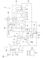
- the gas turbine plant 100 includes a gas turbine 1, an exhaust heat recovery boiler 2, a steam turbine 4, an exhaust gas treatment facility 6, an EGR line L2, an EGR heater 7, and a control device. It is equipped with 90.
- the gas turbine 1 has a compressor 11, a combustor 12, and a turbine 13.
- the compressor 11 compresses the outside air guided through the intake line La to generate high-pressure air.
- an outside air temperature measuring unit To for measuring the temperature of the outside air and an outside air humidity measuring unit H for measuring the humidity of the outside air are provided on the intake line La.
- an intake duct 11D and a filter F arranged in the intake duct 11D are provided.
- the combustor 12 produces high-temperature and high-pressure combustion gas by mixing fuel with the high-pressure air generated by the compressor 11 and burning the fuel.
- the turbine 13 is driven by this combustion gas.
- the rotational energy of the turbine 13 is taken out from the shaft end and used for driving, for example, the generator G.
- the exhaust gas discharged from the turbine 13 is recovered by the exhaust line L1 and sent to the exhaust heat recovery boiler 2.
- the exhaust heat recovery boiler 2 generates superheated steam by exchanging heat between the exhaust gas flowing in the exhaust line L1 and water. This superheated steam is sent to the steam turbine 4 through the first line S1 and used to drive the steam turbine 4. The rotational energy of the steam turbine 4 is used, for example, to drive the generator G.
- the steam discharged from the steam turbine 4 is recovered by the condenser 41. In the condenser 41, steam is condensed to generate water by exchanging heat with a medium guided from the outside. The water generated by the condenser 41 is supplied to the exhaust heat recovery boiler 2 through the fifth line S5.
- An exhaust gas treatment facility 6 is provided on the exhaust line L1 on the downstream side of the exhaust heat recovery boiler 2.
- the exhaust gas treatment facility 6 is provided to keep the exhaust gas flowing in the exhaust line L1 in a clean state and dissipate it to the outside air.
- the exhaust gas treatment equipment 6 includes a carbon dioxide recovery device 3 and an exhaust gas heater 5.
- the carbon dioxide recovery device 3 is a device for recovering and removing carbon dioxide contained in the exhaust gas.
- the carbon dioxide capture device 3 has a cooling tower 31 (quencher), an absorption tower 32, and a regeneration tower 33.
- the cooling tower 31 is a facility for cooling the exhaust gas flowing through the exhaust line L1 prior to the recovery of carbon dioxide in the absorption tower 32 described later.
- the temperature of the exhaust gas flowing through the exhaust line L1 is about 90 ° C.
- the exhaust gas is cooled to about 30 ° C. in the cooling tower 31.
- the exhaust gas cooled by the cooling tower 31 is sent to the absorption tower 32 through the exhaust line L1.
- the absorption tower 32 has a cylindrical shape extending in the vertical direction, and an exhaust line L1 extending from the cooling tower 31 is connected to the lower portion thereof.
- an absorption liquid capable of chemically bonding with carbon dioxide flows from above to below.
- an absorbent include an aqueous solution of an amine containing monoethanolamine (MEA), diethanolamine (DEA), triethanolamine (TEA), diisopropanolamine (DIPA), and methyldiethanolamine (MDEA).
- An organic solvent containing no water, a mixture thereof, and an amino acid-based aqueous solution are preferably used.
- the exhaust gas flowing into the lower part of the absorption tower 32 rises in the absorption tower 32 while contacting the absorption liquid flowing from above. At this time, carbon dioxide contained in the exhaust gas is chemically absorbed by the absorbing liquid. The residual exhaust gas from which carbon dioxide has been removed flows into the exhaust line L1 again from the upper part of the absorption tower 32.
- the absorption liquid that has absorbed carbon dioxide is sent to the regeneration tower 33 through the absorption liquid recovery line L4 connected to the lower part of the absorption tower 32.
- the regeneration tower 33 is a device for regenerating (separating carbon dioxide) the absorbing liquid in a state where carbon dioxide has been absorbed.
- a third line S3 through which steam taken out from the exhaust heat recovery boiler 2 described above flows is connected to the regeneration tower 33.
- a reboiler 34 is provided on the third line S3. Steam from the exhaust heat recovery boiler 2 is supplied to the reboiler 34 through the third line S3. In the reboiler 34, a part of the water contained in the absorbing liquid is heated by the heat exchange with the steam to become stripping steam.
- the stripping steam is sent into the regeneration tower 33 through the absorption liquid extraction line L7.
- the stripping steam comes into contact with the pre-regeneration absorption liquid supplied from the absorption liquid recovery line L4.
- carbon dioxide is dissipated from the absorption liquid before regeneration, and the absorption liquid is regenerated (the state does not contain carbon dioxide).
- the carbon dioxide emitted from the absorption liquid before regeneration is sent from the regeneration tower 33 to a carbon dioxide compression device (not shown). Further, the steam discharged from the reboiler 34 is sent to the above-mentioned condenser 41 through the third line S3.
- a part of the absorbed liquid after regeneration (that is, the component that did not become stripping steam) is sent to the absorbent liquid supply line L5 connected to the lower part of the regeneration tower 33.
- a heat exchanger, a pump, and a cooler (not shown) are provided on the absorbent liquid supply line L5.
- the regenerated absorption liquid is supplied from the regeneration tower 33 to the heat exchanger.
- the absorbed liquid after regeneration is appropriately cooled to a temperature suitable for absorbing carbon dioxide.
- the regenerated absorption liquid at a low temperature is supplied to the upper part of the absorption tower 32.
- the exhaust gas heater 5 heats the exhaust gas in order to suppress whitening of the exhaust gas discharged from the carbon dioxide recovery device 3 via the exhaust line L1.
- the exhaust gas heater 5 is a heat exchanger. Steam (for example, 200 ° C. to 230 ° C.) taken out through the second line S2 branched from the third line S3 described above flows through the exhaust gas heater 5 as a heat medium. That is, the exhaust gas heater 5 uses the steam taken out from the exhaust heat recovery boiler 2 as a heat medium.
- the "steam taken out from the exhaust heat recovery boiler 2" is the steam directly taken out from the exhaust heat recovery boiler 2 and the steam extracted from the exhaust heat recovery boiler 2 after being used for driving the steam turbine 4. Contains at least one of the steam.
- the steam as a heat medium that has passed through the exhaust gas heater 5 is sent as a heat medium to the EGR heater 7, which will be described later, through the second line S2.
- the heat medium may be in a liquid phase state (water) or a gas phase state (steam).
- the EGR line L2 draws at least a part of the exhaust gas that has passed through the cooling tower 31 of the carbon dioxide recovery device 3 and guides it to the intake side (compressor 11) of the gas turbine 1. More specifically, one end of the EGR line L2 is provided on the upstream side (that is, the side in contact with the outside air) of the filter F in the intake duct 11D described above.
- an EGR heater 7 and an exhaust gas temperature measuring unit Te are provided in order from the cooling tower 31 side toward the gas turbine 1 side.
- the EGR heater 7 is a heat exchanger. In the EGR heater 7, heat exchange is performed between the heat medium guided from the exhaust gas heater 5 and the exhaust gas through the second line S2 described above.
- the exhaust gas that has passed through the EGR heater 7 is heated.
- the temperature of the exhaust gas supplied from the cooling tower 31 is about 30 ° C.
- it is desirable that the temperature of the exhaust gas after passing through the EGR heater 7 is about 40 ° C.
- the heat medium that has passed through the EGR heater 7 is guided to the condenser 41 through the second line S2.
- a valve device V (supply amount adjusting unit) is provided between the EGR heater 7 and the condenser 41 on the second line S2.
- the valve device V is a flow rate adjusting valve.
- the opening degree of the valve device V is the humidity of the exhaust gas measured by the temperature of the exhaust gas measured by the exhaust gas temperature measuring unit Te, the temperature of the outside air measured by the outside air temperature measuring unit To, and the outside air measured by the outside air humidity measuring unit H. It is determined and adjusted by the control device 90 based on the humidity of the above.
- the exhaust gas that has passed through the absorption tower 32 is heated by the exhaust gas heater 5.
- the moisture contained in the exhaust gas evaporates, so that the possibility of white smoke when the exhaust gas is released to the outside can be further reduced.
- a part of the exhaust gas discharged from the cooling tower 31 is guided (recirculated) to the intake side of the gas turbine 1 through the EGR line L2.
- the exhaust gas contains moisture, moisture may adhere to the filter F provided in the intake duct 11D of the compressor 11, and the intake resistance may increase. Further, such water may become water droplets and collide with the moving blades of the compressor 11 to generate erosion.
- the EGR line L2 concentrates not only CO2 but also water, the possibility of white smoke tends to increase.
- the exhaust gas flowing through the EGR line L2 is heated by the EGR heater 7.
- the humidity of the exhaust gas is reduced, so that the adhesion of water to the filter F is suppressed.
- an increase in intake resistance can be suppressed.
- the amount of the heat medium supplied to the EGR heater 7 is adjusted based on the temperature of the exhaust gas flowing through the EGR line L2.
- the heating amount of the exhaust gas by the EGR heater 7 can be changed.
- the temperature of the exhaust gas supplied to the gas turbine 1 is too high, the amount of the heat medium is reduced by reducing the opening degree of the valve device V as the supply amount adjusting unit, and the temperature is lowered. Can be changed to.
- the amount of heat medium used can be reduced and the efficiency of the plant can be improved.
- the temperature of the exhaust gas is too low, the temperature can be changed in the direction of increasing by increasing the amount of the heat medium.
- the temperature of the exhaust gas supplied to the gas turbine 1 is optimized, and the moisture content can be kept from being saturated in the mixed gas of the outside air and the exhaust gas.
- the amount of the heat medium supplied to the EGR heater 7 is adjusted based on the temperature of the outside air supplied to the gas turbine 1 in addition to the temperature of the exhaust gas flowing through the EGR line L2.
- the amount of the heat medium is increased by increasing the opening degree of the valve device V as the supply amount adjusting unit, and the temperature of the exhaust gas is raised.
- the temperature of the exhaust gas supplied to the gas turbine 1 is optimized, the temperature of the mixed gas of the outside air and the exhaust gas exceeds the dew point, and the moisture content can be not saturated.
- the amount of the heat medium supplied to the EGR heater 7 is adjusted based on the humidity of the outside air in addition to the temperature of the exhaust gas flowing through the EGR line L2 and the temperature of the outside air. For example, when the humidity of the outside air is excessively high, the temperature of the exhaust gas is raised by increasing the amount of the heat medium supplied to the EGR heater 7. On the other hand, when the humidity of the outside air is excessively low, the temperature of the exhaust gas is lowered by reducing the amount of the heat medium supplied to the EGR heater 7. As a result, the temperature and humidity of the exhaust gas supplied to the gas turbine 1 are optimized, and the moisture content can be kept from being saturated in the mixed gas of the outside air and the exhaust gas.
- the first embodiment of the present disclosure has been described above. It is possible to make various changes and modifications to the above configuration as long as it does not deviate from the gist of the present disclosure.
- the exhaust gas temperature measuring unit Te and the outside air humidity measuring unit H are provided on the EGR line and the outside air temperature measuring unit To is provided on the intake line La has been described.
- the steam turbine 4 has a high-pressure steam turbine 4H and a low-pressure steam turbine 4L.
- the low-pressure steam turbine 4L and the high-pressure steam turbine 4H may be connected coaxially or may be independent of each other.
- the high-pressure steam turbine 4H is driven by steam guided from the exhaust heat recovery boiler 2 through the first line S1.
- the steam that has passed through the high-pressure steam turbine 4H is guided to the low-pressure steam turbine 4L to drive the low-pressure steam turbine 4L.
- the steam that has passed through the low-pressure steam turbine 4L is sent to the condenser 41.
- the sixth line S6 is connected to the middle stage of the high pressure steam turbine 4H.
- the high-temperature steam extracted by the sixth line S6 (for example, 250 ° C. to 350 ° C.) is sent as a heat medium to the auxiliary exhaust gas heater 5B described later. It is also possible to adopt a configuration in which the steam turbine 4 has only one turbine. In this case, it is desirable that the sixth line S6 is connected to the high pressure side stage of the steam turbine 4.
- the auxiliary exhaust gas heater 5B is provided on the downstream side of the exhaust gas heater 5 in the exhaust line L1.
- the auxiliary exhaust gas heater 5B is a heat exchanger that exchanges heat between the steam extracted from the high-pressure steam turbine 4H and the exhaust gas flowing through the exhaust line L1.
- the exhaust gas that has passed through the exhaust gas heater 5 is further heated by the auxiliary exhaust gas heater 5B.
- the moisture content in the exhaust gas is further reduced, and the possibility of white smoke formation can be further reduced.
- the gas turbine plant 100 includes a gas turbine 1, an exhaust heat recovery boiler 2 that generates steam by exchanging heat between the exhaust gas of the gas turbine 1 and water, and the exhaust gas.
- the absorption tower 32 that recovers the carbon dioxide contained in the exhaust gas
- the EGR line L2 that extracts a part of the exhaust gas and guides it to the intake side of the gas turbine 1, and the steam taken out from the exhaust heat recovery boiler 2.
- the exhaust gas heater 5 that heats the exhaust gas by exchanging heat between the heat medium and the exhaust gas that has passed through the absorption tower 32, and the EGR line L2 provided on the EGR line L2.
- the EGR heater 7 is provided to heat the exhaust gas flowing through the EGR line L2 by exchanging heat between the flowing exhaust gas and the heat medium discharged from the exhaust gas heater 5.
- the exhaust gas that has passed through the absorption tower 32 is heated by the exhaust gas heater 5.
- the moisture contained in the exhaust gas evaporates, so that the possibility of white smoke when the exhaust gas is released to the outside can be reduced.
- the gas turbine plant 100 further includes a quencher (cooling tower 31) for cooling the exhaust gas exhausted from the exhaust heat recovery boiler 2, and the EGR line L2 is discharged from the quencher. A part of the exhaust gas is extracted and guided to the intake side of the gas turbine 1.
- a quencher cooling tower 31 for cooling the exhaust gas exhausted from the exhaust heat recovery boiler 2, and the EGR line L2 is discharged from the quencher. A part of the exhaust gas is extracted and guided to the intake side of the gas turbine 1.
- the gas turbine plant 100 according to the third aspect is provided on the intake side of the gas turbine with respect to the EGR heater 7 on the EGR line L2, and the temperature of the exhaust gas flowing through the EGR line L2 is adjusted. Further, an exhaust gas temperature measuring unit Te to be measured and a supply amount adjusting unit (valve device V) for adjusting the amount of the heat medium supplied to the EGR heater 7 based on the temperature of the exhaust gas are further provided.
- the amount of the heat medium supplied to the EGR heater 7 is adjusted based on the temperature of the exhaust gas flowing through the EGR line L2.
- the heating amount of the exhaust gas by the EGR heater 7 can be changed.
- the supply amount adjusting unit reduces the amount of the heat medium, so that the temperature can be changed in the direction of lowering.
- the supply amount adjusting unit can increase the amount of the heat medium to change the temperature in the direction of increasing.
- the gas turbine plant 100 according to the fourth aspect further includes an outside air temperature measuring unit To for measuring the temperature of the outside air supplied to the gas turbine 1, and the supply amount adjusting unit (valve device V) includes the supply amount adjusting unit (valve device V).
- the amount of the heat medium supplied to the EGR heater 7 is adjusted based on the temperature of the exhaust gas and the temperature of the outside air.
- the amount of the heat medium supplied to the EGR heater 7 is adjusted based on the temperature of the outside air supplied to the gas turbine 1 in addition to the temperature of the exhaust gas flowing through the EGR line L2.
- the supply amount adjusting unit reduces the amount of the heat medium to bring the temperature of the exhaust gas closer to the temperature of the outside air.
- the temperature of the exhaust gas supplied to the gas turbine 1 is optimized, and the moisture content can be kept from being saturated in the mixed gas of the outside air and the exhaust gas.
- the gas turbine plant 100 further includes an outside air humidity measuring unit (H) for measuring the humidity of the outside air sucked by the gas turbine, and the supply amount adjusting unit (valve device V) is the above.
- the amount of the heat medium supplied to the EGR heater is adjusted based on the temperature of the exhaust gas, the temperature of the outside air, and the humidity of the outside air.
- the amount of the heat medium supplied to the EGR heater 7 is adjusted based on the temperature of the exhaust gas flowing through the EGR line L2 and the temperature of the outside air as well as the humidity of the outside air.
- the temperature and humidity of the exhaust gas supplied to the gas turbine 1 are optimized, and the moisture content can be kept from being saturated in the mixed gas of the outside air and the exhaust gas.
- the gas turbine plant 100 has passed through the steam turbine 4 driven by the steam generated in the exhaust heat recovery boiler 2, the steam extracted from the steam turbine 4, and the absorption tower 32.
- An auxiliary exhaust gas heater 5B that heats the exhaust gas by exchanging heat with the exhaust gas is further provided.
- the exhaust gas that has passed through the exhaust gas heater 5 is further heated by the auxiliary exhaust gas heater 5B.
- the moisture content in the exhaust gas is further reduced, and the possibility of white smoke can be further reduced.
- the steam turbine 4 includes a high-pressure steam turbine 4H and a low-pressure steam turbine 4L driven by steam discharged from the high-pressure steam turbine 4H, and the auxiliary.
- the exhaust gas heater 5B is provided on the downstream side of the exhaust gas heater 5 in the flow direction of the exhaust gas, and includes steam extracted from the high-pressure steam turbine 4H and exhaust gas that has passed through the exhaust gas heater 5. By exchanging heat with the turbine, the exhaust gas is further heated.
- the exhaust gas that has passed through the exhaust gas heater 5 is further heated by the auxiliary exhaust gas heater 5B.
- the moisture content in the exhaust gas is further reduced, and the possibility of white smoke can be further reduced.
- This disclosure relates to a gas turbine plant. According to the present disclosure, the generation of white smoke can be further suppressed.
Abstract
このガスタービンプラントは、ガスタービンと、ガスタービンの排気ガスと水とを熱交換させることで蒸気を発生させる排熱回収ボイラーと、排気ガスに含まれる二酸化炭素を回収する吸収塔と、排気ガスの一部を抽気して、ガスタービンの吸気側に導くEGRラインと、排熱回収ボイラーから取り出された蒸気を熱媒体として、前記熱媒体と吸収塔を通過した排気ガスとを熱交換させて排気ガスを加熱する排気ガス加熱器と、EGRライン上に設けられ、EGRラインを流通する排気ガスと排気ガス加熱器から排出された熱媒体とを熱交換させることで、EGRラインを流通する排気ガスを加熱するEGR加熱器と、を備える。
Description
本開示は、ガスタービンプラントに関する。本願は、2020年7月20日に出願された特願2020-123749号に対して優先権を主張し、その内容をここに援用する。
化石燃料を用いる発電プラント、例えばガスタービンプラントでは、ガスタービンの運転に伴って排気ガスが発生する。この排気ガスには、二酸化炭素が含まれている。環境保全の観点から、二酸化炭素を可能な限り排気ガスから除去する技術が求められている。このような技術として、例えば下記特許文献1に記載された方法が知られている。特許文献1に係る方法では、排ガスの少なくとも一部を吸収液に接触させることで、当該吸収液によって二酸化炭素を吸着除去する。
ところで、プラントの運転状態によっては、排気ガスに水分(湿分)が含まれる場合がある。このような水分が凝縮すると、排気ガスの排出に際して白煙が発生する。白煙は、周囲の景観を損なうことに加えて、排気ガスの排出口近傍に排気ガスが直接降下することで、微量に残存する排気ガス中の窒素酸化物も随伴されるため、その抑制が求められている。そこで、下記特許文献1に係る技術では、排気ガスの熱によって使用済みの吸収液を加熱・再生させるとともに、再生された吸収液の熱を利用して排気ガスを加熱する方法を採っている。これにより、排気ガス中の水分が蒸発し、白煙の発生を抑制できるとされている。
しかしながら、再生された吸収液の熱は限定的であることから、当該吸収液を用いただけでは排気ガスを十分に加熱することができない虞がある。また、排気ガス中のCO2の回収を容易にするため、排気ガスを吸気に再循環させることによって、排気ガス中のCO2の濃度を高める技術があるが、この場合、同時に、排気ガス中の水分の濃度も高まるため、十分に加熱しないと白煙が発生する可能性が高い。したがって、特許文献1に記載された装置では、依然として白煙が発生してしまう可能性がある。
本開示は上記課題を解決するためになされたものであって、白煙の発生をさらに抑制できるガスタービンプラントを提供することを目的とする。
上記課題を解決するために、本開示に係るガスタービンプラントは、ガスタービンと、前記ガスタービンの排気ガスと水とを熱交換させることで蒸気を発生させる排熱回収ボイラーと、前記排気ガスに含まれる二酸化炭素を回収する吸収塔と、前記排気ガスの一部を抽気して、前記ガスタービンの吸気側に導くEGRラインと、前記排熱回収ボイラーから取り出された蒸気を熱媒体として、前記熱媒体と前記吸収塔を通過した排気ガスとを熱交換させて前記排気ガスを加熱する排気ガス加熱器と、前記EGRライン上に設けられ、前記EGRラインを流通する排気ガスと前記排気ガス加熱器から排出された前記熱媒体とを熱交換させることで、前記EGRラインを流通する排気ガスを加熱するEGR加熱器と、を備える。
本開示のガスタービンプラントによれば、白煙の発生をさらに抑制できる。
<第一実施形態>
(ガスタービンプラントの構成)
以下、本開示の第一実施形態に係るガスタービンプラント100について、図1を参照して説明する。図1に示すように、ガスタービンプラント100は、ガスタービン1と、排熱回収ボイラー2と、蒸気タービン4と、排気ガス処理設備6と、EGRラインL2と、EGR加熱器7と、制御装置90と、を備えている。
(ガスタービンプラントの構成)
以下、本開示の第一実施形態に係るガスタービンプラント100について、図1を参照して説明する。図1に示すように、ガスタービンプラント100は、ガスタービン1と、排熱回収ボイラー2と、蒸気タービン4と、排気ガス処理設備6と、EGRラインL2と、EGR加熱器7と、制御装置90と、を備えている。
(ガスタービンの構成)
ガスタービン1は、圧縮機11と、燃焼器12と、タービン13と、を有している。圧縮機11は、吸気ラインLaを通じて導かれた外気を圧縮して高圧空気を生成する。吸気ラインLa上には、外気の温度を計測する外気温度計測部To、及び外気の湿度を計測する外気湿度計測部Hが設けられている。また、圧縮機11の吸気側には、吸気ダクト11Dと、この吸気ダクト11D内に配置されたフィルタFと、が設けられている。
ガスタービン1は、圧縮機11と、燃焼器12と、タービン13と、を有している。圧縮機11は、吸気ラインLaを通じて導かれた外気を圧縮して高圧空気を生成する。吸気ラインLa上には、外気の温度を計測する外気温度計測部To、及び外気の湿度を計測する外気湿度計測部Hが設けられている。また、圧縮機11の吸気側には、吸気ダクト11Dと、この吸気ダクト11D内に配置されたフィルタFと、が設けられている。
燃焼器12は、圧縮機11が生成した高圧空気に燃料を混合して燃焼させることで高温高圧の燃焼ガスを生成する。タービン13は、この燃焼ガスによって駆動される。タービン13の回転エネルギーは軸端から取り出されて例えば発電機Gの駆動に利用される。タービン13から排出される排気ガスは、排気ラインL1によって回収されて、排熱回収ボイラー2に送られる。
(排熱回収ボイラーの構成)
排熱回収ボイラー2は、排気ラインL1中を流通する排ガスと水とを熱交換させることで過熱蒸気を生成する。この過熱蒸気は、第一ラインS1を通じて蒸気タービン4に送られ、当該蒸気タービン4の駆動に用いられる。蒸気タービン4の回転エネルギーは例えば発電機Gの駆動に利用される。蒸気タービン4から排出された蒸気は復水器41によって回収される。復水器41では、外部から導かれた媒体と熱交換させることで蒸気を凝縮させて水を生成する。復水器41で生成された水は、第五ラインS5を通じて排熱回収ボイラー2に供給される。
排熱回収ボイラー2は、排気ラインL1中を流通する排ガスと水とを熱交換させることで過熱蒸気を生成する。この過熱蒸気は、第一ラインS1を通じて蒸気タービン4に送られ、当該蒸気タービン4の駆動に用いられる。蒸気タービン4の回転エネルギーは例えば発電機Gの駆動に利用される。蒸気タービン4から排出された蒸気は復水器41によって回収される。復水器41では、外部から導かれた媒体と熱交換させることで蒸気を凝縮させて水を生成する。復水器41で生成された水は、第五ラインS5を通じて排熱回収ボイラー2に供給される。
排気ラインL1上であって、排熱回収ボイラー2の下流側には、排ガス処理設備6が設けられている。排ガス処理設備6は、排気ラインL1中を流通する排気ガスを清浄な状態にして外気に放散させるために設けられている。排ガス処理設備6は、二酸化炭素回収装置3と、排気ガス加熱器5と、を有している。
(二酸化炭素回収装置の構成)
二酸化炭素回収装置3は、排気ガス中に含まれる二酸化炭素を回収除去するための装置である。二酸化炭素回収装置3は、冷却塔31(クエンチャ)と、吸収塔32と、再生塔33と、を有している。
二酸化炭素回収装置3は、排気ガス中に含まれる二酸化炭素を回収除去するための装置である。二酸化炭素回収装置3は、冷却塔31(クエンチャ)と、吸収塔32と、再生塔33と、を有している。
冷却塔31は、後述する吸収塔32における二酸化炭素の回収に先立って、排気ラインL1を流通する排気ガスを冷却するための設備である。排気ラインL1を流通する排気ガスの温度が90℃程度である場合、冷却塔31では、30℃程度まで排気ガスが冷却される。冷却塔31で冷却された排気ガスは排気ラインL1を通じて吸収塔32に送られる。
吸収塔32は上下方向に延びる筒状をなしており、その下部には、冷却塔31から延びる排気ラインL1が接続されている。吸収塔32の内部では、二酸化炭素と化学結合することが可能な吸収液が上方から下方に向かって流れている。なお、このような吸収液として具体的には、モノエタノールアミン(MEA)、ジエタノールアミン(DEA)、トリエタノールアミン(TEA)、ジイソプロパノールアミン(DIPA)、メチルジエタノールアミン(MDEA)を含むアミンの水溶液や水を含まない有機溶媒、その混合物、アミノ酸系の水溶液が好適に用いられる。また吸収液はアミン以外を用いても良い。
吸収塔32内の下部に流入した排気ガスは、上方から流れる吸収液に対して接触しながら吸収塔32内を上昇する。この時、排気ガスに含まれる二酸化炭素が吸収液に化学吸収される。二酸化炭素が除去された残余の排気ガスは、吸収塔32の上部から再び排気ラインL1中に流入する。
二酸化炭素を吸収した吸収液は、吸収塔32の下部に接続された吸収液回収ラインL4を通じて再生塔33に送られる。再生塔33は、二酸化炭素を吸収した状態の吸収液を再生する(二酸化炭素を分離する)ための装置である。再生塔33には、上述の排熱回収ボイラー2から取り出された蒸気が流れる第三ラインS3が接続されている。第三ラインS3上には、リボイラー34が設けられている。リボイラー34には、第三ラインS3を通じて排熱回収ボイラー2からの蒸気が供給される。リボイラー34では、この蒸気との熱交換によって、吸収液に含まれる水の一部が加熱されてストリッピングスチームとなる。ストリッピングスチームは、吸収液抽出ラインL7を通じて再生塔33内に送られる。再生塔33内で、ストリッピングスチームは吸収液回収ラインL4から供給された再生前の吸収液と接触する。これにより、再生前の吸収液から二酸化炭素が放散し、吸収液が再生される(二酸化炭素を含まない状態となる)。再生前の吸収液から放散された二酸化炭素は、再生塔33から不図示の二酸化炭素圧縮装置に送られる。また、リボイラー34から排出された蒸気は、第三ラインS3を通じて上述の復水器41に送られる。
再生後の吸収液の一部(即ち、ストリッピングスチームとならなかった成分)は、再生塔33の下部に接続された吸収液供給ラインL5に送られる。吸収液供給ラインL5上には、不図示の熱交換器、ポンプ、及び冷却器が設けられている。ポンプを駆動することにより、再生塔33から熱交換器に、再生後の吸収液が供給される。これにより、再生前の吸収液と再生後の吸収液との間で熱交換が行われる。さらに、冷却器にて、再生後の吸収液は二酸化炭素を吸収するために適した温度へ適宜冷却される。低温となった再生後の吸収液は、吸収塔32の上部に供給される。
(排気ガス加熱器の構成)
排気ガス加熱器5は、排気ラインL1を経て上記の二酸化炭素回収装置3から排出された排気ガスの白煙化を抑制するために排気ガスを加熱する。排気ガス加熱器5は熱交換器である。排気ガス加熱器5には、上述の第三ラインS3から分岐する第二ラインS2を通じて取り出された蒸気(一例として200℃~230℃)が熱媒体として流通する。つまり、排気ガス加熱器5は、排熱回収ボイラー2から取り出された蒸気を熱媒体として利用する。なお、「排熱回収ボイラー2から取り出された蒸気」とは、排熱回収ボイラー2から直接的に取り出された蒸気、及び排熱回収ボイラー2から蒸気タービン4の駆動に用いられた後抽気された蒸気の少なくとも一方を含む。これにより、排気ラインL1を流通する排気ガスと蒸気との間で熱交換が生じ、排気ガスの温度が上昇する。このとき、排気ガス中に含まれる水分(湿分)の少なくとも一部が蒸発する。排気ガス加熱器5を通過した熱媒体としての蒸気は、第二ラインS2を通じて、後述するEGR加熱器7に熱媒体として送られる。熱媒体は液相状態(水)であってもよいし、気相状態(蒸気)であってもよい。
排気ガス加熱器5は、排気ラインL1を経て上記の二酸化炭素回収装置3から排出された排気ガスの白煙化を抑制するために排気ガスを加熱する。排気ガス加熱器5は熱交換器である。排気ガス加熱器5には、上述の第三ラインS3から分岐する第二ラインS2を通じて取り出された蒸気(一例として200℃~230℃)が熱媒体として流通する。つまり、排気ガス加熱器5は、排熱回収ボイラー2から取り出された蒸気を熱媒体として利用する。なお、「排熱回収ボイラー2から取り出された蒸気」とは、排熱回収ボイラー2から直接的に取り出された蒸気、及び排熱回収ボイラー2から蒸気タービン4の駆動に用いられた後抽気された蒸気の少なくとも一方を含む。これにより、排気ラインL1を流通する排気ガスと蒸気との間で熱交換が生じ、排気ガスの温度が上昇する。このとき、排気ガス中に含まれる水分(湿分)の少なくとも一部が蒸発する。排気ガス加熱器5を通過した熱媒体としての蒸気は、第二ラインS2を通じて、後述するEGR加熱器7に熱媒体として送られる。熱媒体は液相状態(水)であってもよいし、気相状態(蒸気)であってもよい。
EGRラインL2は、二酸化炭素回収装置3の冷却塔31を通過した排気ガスの少なくとも一部を抽気して、ガスタービン1の吸気側(圧縮機11)に導く。より具体的には、EGRラインL2の一端は、上述した吸気ダクト11D内におけるフィルタFよりも上流側(つまり、外気に接する側)に設けられている。EGRラインL2上には、冷却塔31側からガスタービン1側に向かって順に、EGR加熱器7、及び排ガス温度計測部Teが設けられている。EGR加熱器7は熱交換器である。EGR加熱器7では、上記の第二ラインS2を通じて排気ガス加熱器5から導かれた熱媒体と排気ガスとの間で熱交換が行われる。これにより、EGR加熱器7を通過した排気ガスは加熱される。一例として、冷却塔31から供給される排気ガスの温度が30℃程度である場合、EGR加熱器7を通過した後の排気ガスの温度は40℃程度とされることが望ましい。
EGR加熱器7を通過した熱媒体は、第二ラインS2を通じて復水器41に導かれる。第二ラインS2上におけるEGR加熱器7と復水器41との間には、弁装置V(供給量調整部)が設けられている。この弁装置Vの開度を変化させることで、第二ラインS2を流通する熱媒体の流量が変化する。つまり、弁装置Vは流量調整弁である。弁装置Vの開度は、排ガス温度計測部Teが計測した排気ガスの温度が計測した排気ガスの湿度、外気温度計測部Toが計測した外気の温度、及び外気湿度計測部Hが計測した外気の湿度に基づいて、制御装置90によって決定・調整される。
(作用効果)
上記構成によれば、吸収塔32を通過した排気ガスは、排気ガス加熱器5によって加熱される。これにより、当該排気ガスに含まれる湿分が蒸発するため、排気ガスが外部に放散される際に白煙化する可能性をより一層低減することができる。さらに、上記構成では、EGRラインL2を通じて、冷却塔31から排出された排気ガスの一部がガスタービン1の吸気側に導かれる(再循環する)。このとき、排気ガス中に湿分が含まれていると、圧縮機11の吸気ダクト11Dに設けられたフィルタFに水分が付着して、吸気抵抗が増加する恐れがある。また、このような水分が水滴となって圧縮機11の動翼に衝突することで、エロージョンを発生させる虞もある。さらに、EGRラインL2によって、CO2のみならず、水分も濃縮されるため、白煙が生じる可能性が高くなる傾向にある。上記構成では、EGRラインL2を流通する排気ガスは、EGR加熱器7によって加熱される。これにより、当該排気ガスの湿度が低減されるため、フィルタFへの水分付着が抑制される。この結果、吸気抵抗の増加を抑えることができる。
上記構成によれば、吸収塔32を通過した排気ガスは、排気ガス加熱器5によって加熱される。これにより、当該排気ガスに含まれる湿分が蒸発するため、排気ガスが外部に放散される際に白煙化する可能性をより一層低減することができる。さらに、上記構成では、EGRラインL2を通じて、冷却塔31から排出された排気ガスの一部がガスタービン1の吸気側に導かれる(再循環する)。このとき、排気ガス中に湿分が含まれていると、圧縮機11の吸気ダクト11Dに設けられたフィルタFに水分が付着して、吸気抵抗が増加する恐れがある。また、このような水分が水滴となって圧縮機11の動翼に衝突することで、エロージョンを発生させる虞もある。さらに、EGRラインL2によって、CO2のみならず、水分も濃縮されるため、白煙が生じる可能性が高くなる傾向にある。上記構成では、EGRラインL2を流通する排気ガスは、EGR加熱器7によって加熱される。これにより、当該排気ガスの湿度が低減されるため、フィルタFへの水分付着が抑制される。この結果、吸気抵抗の増加を抑えることができる。
上記構成によれば、EGRラインL2を流通する排気ガスの温度に基づいて、EGR加熱器7に供給される熱媒体の量が調整される。これにより、EGR加熱器7による排気ガスの加熱量を変化させることができる。例えば、ガスタービン1に供給される排気ガスの温度が高すぎる場合には、供給量調整部としての弁装置Vの開度を小さくすることで熱媒体の量を減らし、当該温度を低くなる方向に変化させることができる。これにより、使用される熱媒体の量が削減され、プラントの効率を向上させることができる。反対に、排気ガスの温度が低すぎる場合には、熱媒体の量を増やすことで、当該温度を高くなる方向に変化させることができる。その結果、ガスタービン1に供給される排気ガスの温度が最適化され、外気と排気ガスとの混合ガス中で湿分が飽和しない状態とすることができる。
上記構成によれば、EGRラインL2を流通する排気ガスの温度に加えて、ガスタービン1に供給される外気の温度にも基づいて、EGR加熱器7に供給される熱媒体の量が調整される。例えば、外気の温度が低い場合には、供給量調整部としての弁装置Vの開度を大きくすることで熱媒体の量を増やし、排気ガスの温度を上昇させる。その結果、ガスタービン1に供給される排気ガスの温度が最適化され、外気と排気ガスとの混合ガスの温度が露点を上回り、湿分が飽和しない状態とすることができる。
上記構成によれば、EGRラインL2を流通する排気ガスの温度と外気の温度に加えて、外気の湿度にも基づいて、EGR加熱器7に供給される熱媒体の量が調整される。例えば、外気の湿度が過度に高い場合には、EGR加熱器7に供給される熱媒体の量を増やすことで、排気ガスの温度を上げる。一方で、外気の湿度が過度に低い場合には、EGR加熱器7に供給される熱媒体の量を減らすことで、排気ガスの温度を下げる。その結果、ガスタービン1に供給される排気ガスの温度、及び湿度が最適化され、外気と排気ガスとの混合ガス中で湿分が飽和しない状態とすることができる。
以上、本開示の第一実施形態について説明した。なお、本開示の要旨を逸脱しない限りにおいて、上記の構成に種々の変更や改修を施すことが可能である。例えば、上記第一実施形態では、EGRライン上に排ガス温度計測部Te、及び外気湿度計測部Hが設けられ、吸気ラインLa上には外気温度計測部Toが設けられている例について説明した。しかしながら、外気温度計測部Toを設けない構成や、外気湿度計測部Hを設けない構成を採ることも可能である。つまり、排ガス温度計測部Teのみを備える構成を採ることが可能である。
<第二実施形態>
次いで、本開示の第二実施形態について、図2を参照して説明する。なお、上記第一実施形態と同様の構成については同一の符号を付し、詳細な説明を省略する。本実施形態では、蒸気タービン4の構成が第一実施形態とは異なっている。また、本実施形態では、第一実施形態で説明した排気ガス加熱器5に加えて、補助排気ガス加熱器5Bをさらに備えている。
次いで、本開示の第二実施形態について、図2を参照して説明する。なお、上記第一実施形態と同様の構成については同一の符号を付し、詳細な説明を省略する。本実施形態では、蒸気タービン4の構成が第一実施形態とは異なっている。また、本実施形態では、第一実施形態で説明した排気ガス加熱器5に加えて、補助排気ガス加熱器5Bをさらに備えている。
蒸気タービン4は、高圧蒸気タービン4Hと、低圧蒸気タービン4Lと、を有している。低圧蒸気タービン4Lと高圧蒸気タービン4Hは、同軸上に接続されていてもよいし、互いに独立していてもよい。高圧蒸気タービン4Hは、第一ラインS1を通じて排熱回収ボイラー2から導かれた蒸気によって駆動する。高圧蒸気タービン4Hを通過した蒸気は、低圧蒸気タービン4Lに導かれて当該低圧蒸気タービン4Lを駆動する。低圧蒸気タービン4Lを通過した蒸気は復水器41に送られる。
高圧蒸気タービン4Hの中間段には、第六ラインS6が接続されている。第六ラインS6によって抽気された高温の蒸気(一例として250℃~350℃)は、後述する補助排気ガス加熱器5Bに熱媒体として送られる。なお、蒸気タービン4が1つのみのタービンを有する構成を採ることも可能である。この場合、第六ラインS6は、蒸気タービン4の高圧側の段に接続されることが望ましい。
補助排気ガス加熱器5Bは、排気ラインL1における排気ガス加熱器5の下流側に設けられている。補助排気ガス加熱器5Bは熱交換器であり、高圧蒸気タービン4Hから抽気された蒸気と、排気ラインL1を流通する排気ガスとの間で熱交換をさせる。
また、本実施形態では、補助排気ガス加熱器5Bを通過した熱媒体としての蒸気を、補助ラインS7を通じて、第二ラインS2に導くことが可能とされている。
上記構成によれば、排気ガス加熱器5を通過した排気ガスは、補助排気ガス加熱器5Bによってさらに加熱される。これにより、排気ガス中に含まれる湿分がさらに減少し、白煙化が生じる可能性をより一層低減することができる。
以上、本開示の第二実施形態について説明した。なお、本開示の要旨を逸脱しない限りにおいて、上記の構成に種々の変更や改修を施すことが可能である。
例えば、各実施形態に共通する変形例として、蒸気タービン4から抽気された蒸気のみがEGR加熱器7に熱媒体として供給される構成を採ることも可能である。また、EGR加熱器7の熱媒体として、排熱回収ボイラー2から取り出された蒸気のみを用いることも可能である。さらに、これら蒸気タービン4から抽気された蒸気と排熱回収ボイラー2から取り出された蒸気とを併用することも可能である。このように、EGR加熱器7の熱媒体としては3種類の態様が考えられる。
また、排気ガス加熱器5は、蒸気タービン4から抽気された蒸気のみを熱媒体として用いることも可能である。さらに、上記実施形態のように排熱回収ボイラー2のみを排気ガス加熱器5の熱媒体とすることも可能である。排熱回収ボイラー2から取り出された蒸気と蒸気タービン4から抽気された蒸気とを併用して排気ガス加熱器5の熱媒体とすることも可能である。このように、排気ガス加熱器5の熱媒体としては3種類の態様が考えられる。つまり、上述のEGR加熱器7の熱媒体との組み合わせとして、計9種類の構成が考えられる。これら9種類の組み合わせから設計や仕様に応じて好適な構成を適宜選択することが可能である。
また、排気ガス加熱器5は、蒸気タービン4から抽気された蒸気のみを熱媒体として用いることも可能である。さらに、上記実施形態のように排熱回収ボイラー2のみを排気ガス加熱器5の熱媒体とすることも可能である。排熱回収ボイラー2から取り出された蒸気と蒸気タービン4から抽気された蒸気とを併用して排気ガス加熱器5の熱媒体とすることも可能である。このように、排気ガス加熱器5の熱媒体としては3種類の態様が考えられる。つまり、上述のEGR加熱器7の熱媒体との組み合わせとして、計9種類の構成が考えられる。これら9種類の組み合わせから設計や仕様に応じて好適な構成を適宜選択することが可能である。
<付記>
各実施形態に記載のガスタービンプラント100は、例えば以下のように把握される。
各実施形態に記載のガスタービンプラント100は、例えば以下のように把握される。
(1)第1の態様に係るガスタービンプラント100は、ガスタービン1と、前記ガスタービン1の排気ガスと水とを熱交換させることで蒸気を発生させる排熱回収ボイラー2と、前記排気ガスに含まれる二酸化炭素を回収する吸収塔32と、前記排気ガスの一部を抽気して、前記ガスタービン1の吸気側に導くEGRラインL2と、前記排熱回収ボイラー2から取り出された蒸気を熱媒体として、前記熱媒体と前記吸収塔32を通過した排気ガスとを熱交換させて前記排気ガスを加熱する排気ガス加熱器5と、前記EGRラインL2上に設けられ、前記EGRラインL2を流通する排気ガスと前記排気ガス加熱器5から排出された前記熱媒体とを熱交換させることで、前記EGRラインL2を流通する排気ガスを加熱するEGR加熱器7と、を備える。
上記構成によれば、吸収塔32を通過した排気ガスは、排気ガス加熱器5によって加熱される。これにより、当該排気ガスに含まれる湿分が蒸発するため、排気ガスが外部に放散される際に白煙化する可能性を低減することができる。
(2)第2の態様に係るガスタービンプラント100は、前記排熱回収ボイラー2から排気された排気ガスを冷却するクエンチャ(冷却塔31)をさらに備え、前記EGRラインL2は、前記クエンチャから排出された排気ガスの一部を抽気して、前記ガスタービン1の吸気側に導く。
上記構成では、EGRラインL2を通じて、クエンチャから排出された排気ガスの一部がガスタービン1の吸気側に導かれる(再循環する)。このとき、排気ガス中に湿分が含まれていると、圧縮機11の吸気ダクト11Dに設けられたフィルタFに水分が付着して、吸気抵抗が増加してしまう。しかしながら、上記構成では、EGRラインL2を流通する排気ガスは、EGR加熱器7によって加熱される。これにより、当該排気ガス中に含まれる湿度が低減され、外気と排気ガスとの混合ガス中で湿分が飽和しない状態とすることができる。
(3)第3の態様に係るガスタービンプラント100は、前記EGRラインL2上における前記EGR加熱器7よりも前記ガスタービンの吸気側に設けられ、前記EGRラインL2を流通する排気ガスの温度を計測する排ガス温度計測部Teと、前記排気ガスの温度に基づいて、前記EGR加熱器7に供給される前記熱媒体の量を調整する供給量調整部(弁装置V)と、をさらに備える。
上記構成によれば、EGRラインL2を流通する排気ガスの温度に基づいて、EGR加熱器7に供給される熱媒体の量が調整される。これにより、EGR加熱器7による排気ガスの加熱量を変化させることができる。例えば、ガスタービン1に供給される排気ガスの温度が高すぎる場合には、供給量調整部が熱媒体の量を減らすことで、当該温度を低くなる方向に変化させることができる。反対に、排気ガスの温度が低すぎる場合には、供給量調整部が熱媒体の量を増やすことで、当該温度を高くなる方向に変化させることができる。その結果、ガスタービン1に供給される排気ガスの温度が最適化され、外気と排気ガスとの混合ガス中で湿分が飽和しない状態とすることができる。
(4)第4の態様に係るガスタービンプラント100は、前記ガスタービン1に供給される外気の温度を計測する外気温度計測部Toをさらに備え、前記供給量調整部(弁装置V)は、前記排気ガスの温度、及び前記外気の温度に基づいて、前記EGR加熱器7に供給される前記熱媒体の量を調整する。
上記構成によれば、EGRラインL2を流通する排気ガスの温度に加えて、ガスタービン1に供給される外気の温度にも基づいて、EGR加熱器7に供給される熱媒体の量が調整される。例えば、外気の温度が排気ガスの温度よりも低い場合には、供給量調整部は熱媒体の量を減らすことで、排気ガスの温度を外気の温度に近づける。その結果、ガスタービン1に供給される排気ガスの温度が最適化され、外気と排気ガスとの混合ガス中で湿分が飽和しない状態とすることができる。
(5)第5の態様に係るガスタービンプラント100は、前記ガスタービンが吸い込む外気の湿度を計測する外気湿度計測部(H)をさらに備え、前記供給量調整部(弁装置V)は、前記排気ガスの温度、外気の温度、及び外気の湿度に基づいて、前記EGR加熱器に供給される前記熱媒体の量を調整する。
上記構成によれば、EGRラインL2を流通する排気ガスの温度、及び外気の温度に加えて、外気の湿度にも基づいて、EGR加熱器7に供給される熱媒体の量が調整される。その結果、ガスタービン1に供給される排気ガスの温度、及び湿度が最適化され、外気と排気ガスとの混合ガス中で湿分が飽和しない状態とすることができる。
(6)第6の態様に係るガスタービンプラント100は、前記排熱回収ボイラー2で発生した蒸気によって駆動する蒸気タービン4と、前記蒸気タービン4から抽気された蒸気と前記吸収塔32を通過した排気ガスとを熱交換させることで、排気ガスを加熱する補助排気ガス加熱器5Bと、をさらに備える。
上記構成によれば、排気ガス加熱器5を通過した排気ガスは、補助排気ガス加熱器5Bによってさらに加熱される。これにより、排気ガス中に含まれる湿分がさらに減少し、白煙化の可能性をより一層低減することができる。
(7)第7の態様に係るガスタービンプラント100において、前記蒸気タービン4は、高圧蒸気タービン4Hと、前記高圧蒸気タービン4Hから排出された蒸気によって駆動する低圧蒸気タービン4Lとを備え、前記補助排気ガス加熱器5Bは、前記排気ガス加熱器5の前記排気ガスの流れ方向の下流側に設けられ、前記高圧蒸気タービン4Hから抽気された蒸気と前記排気ガス加熱器5を通過した排気ガスとを熱交換させることで、排気ガスをさらに加熱する。
上記構成によれば、排気ガス加熱器5を通過した排気ガスは、補助排気ガス加熱器5Bによってさらに加熱される。これにより、排気ガス中に含まれる湿分がさらに減少し、白煙化の可能性をより一層低減することができる。
本開示は、ガスタービンプラントに関する。本開示によれば、白煙の発生をさらに抑制できる。
100 ガスタービンプラント
1 ガスタービン
2 排熱回収ボイラー
3 二酸化炭素回収装置
4 蒸気タービン
4H 高圧蒸気タービン
4L 低圧蒸気タービン
5 排気ガス加熱器
5B 補助排気ガス加熱器
6 排気ガス処理設備
7 EGR加熱器
11 圧縮機
11D 吸気ダクト
12 燃焼器
13 タービン
31 冷却塔(クエンチャ)
32 吸収塔
33 再生塔
34 リボイラー
90 制御装置
F フィルタ
G 発電機
H 外気湿度計測部
P 給水ポンプ
Te 排ガス温度計測部
To 外気温度計測部
L1 排気ライン
L2 EGRライン
L4 吸収液回収ライン
L5 吸収液供給ライン
L6 冷却ライン
L7 吸収液抽出ライン
S1 第一ライン
S2 第二ライン
S3 第三ライン
S4 第四ライン
S5 第五ライン
S6 第六ライン
V 弁装置(供給量調整部)
Claims (7)
- ガスタービンと、
前記ガスタービンの排気ガスと水とを熱交換させることで蒸気を発生させる排熱回収ボイラーと、
前記排気ガスに含まれる二酸化炭素を回収する吸収塔と、
前記排気ガスの一部を抽気して、前記ガスタービンの吸気側に導くEGRラインと、
前記排熱回収ボイラーから取り出された蒸気を熱媒体として、前記熱媒体と前記吸収塔を通過した排気ガスとを熱交換させて前記排気ガスを加熱する排気ガス加熱器と、
前記EGRライン上に設けられ、前記EGRラインを流通する排気ガスと前記排気ガス加熱器から排出された前記熱媒体とを熱交換させることで、前記EGRラインを流通する排気ガスを加熱するEGR加熱器と、
を備えるガスタービンプラント。 - 前記排熱回収ボイラーから排気された排気ガスを冷却するクエンチャをさらに備え、
前記EGRラインは、前記クエンチャから排出された排気ガスの一部を抽気して、前記ガスタービンの吸気側に導く請求項1に記載のガスタービンプラント。 - 前記EGRライン上における前記EGR加熱器よりも前記ガスタービンの吸気側に設けられ、前記EGRラインを流通する排気ガスの温度を計測する排ガス温度計測部と、
前記排気ガスの温度に基づいて、前記EGR加熱器に供給される前記熱媒体の量を調整する供給量調整部と、
をさらに備える請求項1又は2に記載のガスタービンプラント。 - 前記ガスタービンに供給される外気の温度を計測する外気温度計測部をさらに備え、
前記供給量調整部は、前記排気ガスの温度、及び前記外気の温度に基づいて、前記EGR加熱器に供給される前記熱媒体の量を調整する請求項3に記載のガスタービンプラント。 - 前記ガスタービンが吸い込む外気の湿度を計測する外気湿度計測部をさらに備え、
前記供給量調整部は、前記排気ガスの温度、外気の温度、及び外気の湿度に基づいて、前記EGR加熱器に供給される前記熱媒体の量を調整する請求項3又は4に記載のガスタービンプラント。 - 前記排熱回収ボイラーで発生した蒸気によって駆動する蒸気タービンと、
前記蒸気タービンから抽気された蒸気と前記吸収塔を通過した排気ガスとを熱交換させることで、排気ガスを加熱する補助排気ガス加熱器と、
をさらに備える請求項1から5のいずれか一項に記載のガスタービンプラント。 - 前記蒸気タービンは、高圧蒸気タービンと、
前記高圧蒸気タービンから排出された蒸気によって駆動する低圧蒸気タービンとを備え、
前記補助排気ガス加熱器は、前記排気ガス加熱器の前記排気ガスの流れ方向の下流側に設けられ、前記高圧蒸気タービンから抽気された蒸気と前記排気ガス加熱器を通過した排気ガスとを熱交換させることで、排気ガスをさらに加熱する請求項6に記載のガスタービンプラント。
Priority Applications (2)
| Application Number | Priority Date | Filing Date | Title |
|---|---|---|---|
| EP21846784.3A EP4166764A4 (en) | 2020-07-20 | 2021-07-20 | GAS TURBINE POWER PLANT |
| US18/015,788 US20230258124A1 (en) | 2020-07-20 | 2021-07-20 | Gas turbine plant |
Applications Claiming Priority (2)
| Application Number | Priority Date | Filing Date | Title |
|---|---|---|---|
| JP2020-123749 | 2020-07-20 | ||
| JP2020123749A JP2022020324A (ja) | 2020-07-20 | 2020-07-20 | ガスタービンプラント |
Publications (1)
| Publication Number | Publication Date |
|---|---|
| WO2022019295A1 true WO2022019295A1 (ja) | 2022-01-27 |
Family
ID=79729154
Family Applications (1)
| Application Number | Title | Priority Date | Filing Date |
|---|---|---|---|
| PCT/JP2021/027085 WO2022019295A1 (ja) | 2020-07-20 | 2021-07-20 | ガスタービンプラント |
Country Status (4)
| Country | Link |
|---|---|
| US (1) | US20230258124A1 (ja) |
| EP (1) | EP4166764A4 (ja) |
| JP (1) | JP2022020324A (ja) |
| WO (1) | WO2022019295A1 (ja) |
Citations (4)
| Publication number | Priority date | Publication date | Assignee | Title |
|---|---|---|---|---|
| JP2007170307A (ja) * | 2005-12-22 | 2007-07-05 | Mitsubishi Heavy Ind Ltd | ガスタービンコンバインドサイクルプラント及び発電方法。 |
| JP2009247932A (ja) | 2008-04-02 | 2009-10-29 | Chiyoda Kako Kensetsu Kk | 排ガス熱源を利用した二酸化炭素の除去方法 |
| JP2013029305A (ja) * | 2011-07-27 | 2013-02-07 | Alstom Technology Ltd | 排気ガス再循環を備えるガスタービン発電機を作動するために方法 |
| JP2020123749A (ja) | 2020-05-07 | 2020-08-13 | 株式会社Fuji | ノズル管理装置 |
Family Cites Families (3)
| Publication number | Priority date | Publication date | Assignee | Title |
|---|---|---|---|---|
| EP2248999A1 (en) * | 2008-12-24 | 2010-11-10 | Alstom Technology Ltd | Power plant with CO2 capture |
| EP2290202A1 (en) * | 2009-07-13 | 2011-03-02 | Siemens Aktiengesellschaft | Cogeneration plant and cogeneration method |
| CA2858631C (en) * | 2011-12-19 | 2017-01-10 | Alstom Technology Ltd. | Control of the gas composition in a gas turbine power plant with flue gas recirculation |
-
2020
- 2020-07-20 JP JP2020123749A patent/JP2022020324A/ja active Pending
-
2021
- 2021-07-20 US US18/015,788 patent/US20230258124A1/en active Pending
- 2021-07-20 EP EP21846784.3A patent/EP4166764A4/en active Pending
- 2021-07-20 WO PCT/JP2021/027085 patent/WO2022019295A1/ja unknown
Patent Citations (4)
| Publication number | Priority date | Publication date | Assignee | Title |
|---|---|---|---|---|
| JP2007170307A (ja) * | 2005-12-22 | 2007-07-05 | Mitsubishi Heavy Ind Ltd | ガスタービンコンバインドサイクルプラント及び発電方法。 |
| JP2009247932A (ja) | 2008-04-02 | 2009-10-29 | Chiyoda Kako Kensetsu Kk | 排ガス熱源を利用した二酸化炭素の除去方法 |
| JP2013029305A (ja) * | 2011-07-27 | 2013-02-07 | Alstom Technology Ltd | 排気ガス再循環を備えるガスタービン発電機を作動するために方法 |
| JP2020123749A (ja) | 2020-05-07 | 2020-08-13 | 株式会社Fuji | ノズル管理装置 |
Non-Patent Citations (1)
| Title |
|---|
| See also references of EP4166764A4 |
Also Published As
| Publication number | Publication date |
|---|---|
| EP4166764A1 (en) | 2023-04-19 |
| US20230258124A1 (en) | 2023-08-17 |
| EP4166764A4 (en) | 2023-11-22 |
| JP2022020324A (ja) | 2022-02-01 |
Similar Documents
| Publication | Publication Date | Title |
|---|---|---|
| JP5100294B2 (ja) | 発電プラントエミッションを低減するためのシステム | |
| WO2008090168A1 (en) | Process for reducing carbon dioxide emission in a power plant | |
| WO2011105120A1 (ja) | Co2回収装置およびco2回収方法 | |
| JP2010235395A (ja) | 二酸化炭素回収装置および二酸化炭素回収装置を備えた火力発電システム | |
| JP2010112377A (ja) | ガスタービンシステム内の腐食を低減するためのシステム及び方法 | |
| US20180216532A1 (en) | System and method for treating exhaust gas | |
| WO2021015260A1 (ja) | ガスタービンプラント | |
| JP7330718B2 (ja) | ガスタービンプラント、及びその排出二酸化炭素回収方法 | |
| CA2883111C (en) | Heat recovery system and heat recovery method | |
| WO2022019295A1 (ja) | ガスタービンプラント | |
| JP4929227B2 (ja) | 高湿分空気利用ガスタービンシステム | |
| WO2021131459A1 (ja) | 排気ガス処理設備、及びガスタービンプラント | |
| WO2008090166A1 (en) | Process for enabling constant power output in a power plant integrated with a carbon dioxide capture unit | |
| WO2014129391A1 (ja) | Co2回収システム及びco2回収方法 | |
| JPWO2014058007A1 (ja) | 二酸化炭素回収システム |
Legal Events
| Date | Code | Title | Description |
|---|---|---|---|
| 121 | Ep: the epo has been informed by wipo that ep was designated in this application |
Ref document number: 21846784 Country of ref document: EP Kind code of ref document: A1 |
|
| ENP | Entry into the national phase |
Ref document number: 2021846784 Country of ref document: EP Effective date: 20230110 |
|
| NENP | Non-entry into the national phase |
Ref country code: DE |