WO2022018951A1 - 原子セル及びその製造方法 - Google Patents
原子セル及びその製造方法 Download PDFInfo
- Publication number
- WO2022018951A1 WO2022018951A1 PCT/JP2021/019167 JP2021019167W WO2022018951A1 WO 2022018951 A1 WO2022018951 A1 WO 2022018951A1 JP 2021019167 W JP2021019167 W JP 2021019167W WO 2022018951 A1 WO2022018951 A1 WO 2022018951A1
- Authority
- WO
- WIPO (PCT)
- Prior art keywords
- hole
- main surface
- lid member
- cell body
- atomic
- Prior art date
- Legal status (The legal status is an assumption and is not a legal conclusion. Google has not performed a legal analysis and makes no representation as to the accuracy of the status listed.)
- Ceased
Links
Images




Classifications
-
- H—ELECTRICITY
- H01—ELECTRIC ELEMENTS
- H01S—DEVICES USING THE PROCESS OF LIGHT AMPLIFICATION BY STIMULATED EMISSION OF RADIATION [LASER] TO AMPLIFY OR GENERATE LIGHT; DEVICES USING STIMULATED EMISSION OF ELECTROMAGNETIC RADIATION IN WAVE RANGES OTHER THAN OPTICAL
- H01S1/00—Masers, i.e. devices using stimulated emission of electromagnetic radiation in the microwave range
- H01S1/06—Gaseous, i.e. beam masers
-
- H—ELECTRICITY
- H03—ELECTRONIC CIRCUITRY
- H03L—AUTOMATIC CONTROL, STARTING, SYNCHRONISATION OR STABILISATION OF GENERATORS OF ELECTRONIC OSCILLATIONS OR PULSES
- H03L7/00—Automatic control of frequency or phase; Synchronisation
- H03L7/26—Automatic control of frequency or phase; Synchronisation using energy levels of molecules, atoms, or subatomic particles as a frequency reference
Definitions
- the present invention relates to an atomic cell and a method for producing the same.
- Atomic clocks are equipped with an atomic oscillator that oscillates based on energy transitions in alkali metal atoms such as cesium (Cs) and rubidium (Rb), and this atomic clock is an oscillator that can obtain highly accurate oscillation characteristics over the long term.
- alkali metal atoms such as cesium (Cs) and rubidium (Rb)
- Cs cesium
- Rb rubidium
- the operating principle of an atomic oscillator can be divided into several methods, but an atomic oscillator using the quantum interference effect (CPT: Coherent Population Trapping) has a frequency stability that is about three orders of magnitude higher than that of a crystal oscillator. It has been known.
- CPT Coherent Population Trapping
- a gaseous alkali metal is enclosed in an atomic cell and used.
- a buffer gas such as nitrogen (N 2 ), neon (Ne), or argon (Ar) is further enclosed in the atomic cell and used.
- Patent Document 1 discloses an example of an atomic cell.
- This atomic cell has a fuselage portion having two through holes and a pair of window portions that close the openings of the two through holes.
- the portion surrounded by one through hole and a pair of windows is a gas accommodating portion, and a gaseous alkali metal is enclosed.
- the portion surrounded by the other through hole and the pair of windows is a metal sump, and is filled with a liquid or solid alkali metal.
- the body portion is provided with a groove portion for communicating the two through holes.
- An object of the present invention is to provide an atomic cell and a method for producing the same, which can facilitate the placement of an alkali metal and increase the productivity.
- the atomic cell according to the present invention has a first main surface and a second main surface facing each other, and has a first through hole and a first through hole penetrating between the first main surface and the second main surface.
- a cell body having two through holes, a first inner wall surface surrounding the first through hole, and a second inner wall surface surrounding the second through hole, and a cell body of the cell body.
- a first lid member provided on the first main surface and closing one side of the first through hole and the second through hole, and provided on the second main surface of the cell body.
- the second through hole is provided with a first through hole and a second lid member that closes the other side of the second through hole, and the second through hole is directed inward from the end on the first main surface side. It is characterized by having a reduced diameter portion that reduces the diameter.
- the portion surrounded by the second inner wall surface, the first lid member and the second lid member is an ampoule arrangement portion in which an ampoule containing an alkali metal is arranged.
- the first through hole has a reduced diameter portion whose diameter is reduced inward from the end portion on the first main surface side.
- the cell body has a partition wall portion located between the first through hole and the second through hole, and the cell body is provided with a communication portion for communicating the first through hole and the second through hole.
- the communication portion is located between the end portion of the partition wall portion on the first main surface side and the first lid member, and the first through hole and the second through hole are formed. It is preferably located in the reduced diameter portion.
- the first through hole has a reduced diameter portion that is reduced in diameter from the end portion on the second main surface side toward the inside, and the second through hole is inward from the end portion on the second main surface side. It is preferable to have a reduced diameter portion whose diameter is reduced toward the diameter.
- the communication portion is the first communication portion, and the cell body is provided with a second communication portion for communicating the first through hole and the second through hole, and the second communication portion is the partition wall portion. It is located between the end on the second main surface side and the second lid member, and is located in the front first through hole and the reduced diameter portion of the second through hole. Is preferable.
- the cell body is made of glass.
- the method for manufacturing an atomic cell according to the present invention is a method for manufacturing the above-mentioned atomic cell, the cell body having a first main surface, a second main surface, a first through hole, and a second through hole.
- the cell body is obtained by forming a reduced diameter portion that is reduced inward toward the inside at the end portion of the second through hole on the first main surface side by the step of forming the intermediate body of the above and etching. It is characterized by comprising a step, a step of joining a first lid member on a first main surface of a cell body, and a step of joining a second lid member on a second main surface of the cell body.
- FIG. 1 is a front sectional view showing an atomic cell according to the first embodiment of the present invention.
- FIG. 2 is a perspective view of the atomic cell according to the first embodiment of the present invention, in which the first lid member is omitted.
- 3 (a) to 3 (c) are enlarged front sectional views of the first lid member side of the atomic cell according to the first embodiment and the first and second modifications thereof.
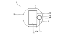
- FIG. 4 is a plan view of the cell body according to the first embodiment of the present invention.
- FIG. 5 is a front sectional view showing a state in which the ampoule is arranged in the second through hole of the cell body.
- FIG. 6 is a front sectional view for explaining an example of a method of encapsulating an alkali metal in a first through hole of an atomic cell.
- FIG. 7 is a perspective view for explaining an example of a step of preparing a preform in the method for manufacturing an atomic cell of the present invention.
- FIG. 8 is a perspective view for explaining an example of a step of obtaining an intermediate in the method for producing an atomic cell of the present invention.
- FIG. 9 is a front sectional view for explaining an example of a step of obtaining a cell body in the method for manufacturing an atomic cell of the present invention.
- FIG. 10 is a front sectional view showing an atomic cell according to a second embodiment of the present invention.
- FIG. 1 is a front sectional view showing an atomic cell according to the first embodiment of the present invention.
- FIG. 2 is a perspective view of the atomic cell according to the first embodiment, omitting the first lid member.
- 3 (a) to 3 (c) are enlarged front sectional views of the first lid member side of the atomic cell according to the first embodiment and the first and second modifications thereof. Note that FIG. 1 is a cross-sectional view taken along the line I-I in FIG.
- the atomic cell 1 includes a cell body 2, a first lid member 3 and a second lid member 4.
- the cell body 2 has a first main surface 5 and a second main surface 6.
- the first main surface 5 and the second main surface 6 face each other.
- the cell body 2 is provided with a first through hole 13, a second through hole 14, and a communication portion 15.
- the first through hole 13 and the second through hole 14 penetrate between the first main surface 5 and the second main surface 6.
- the directions in which the first through hole 13 and the second through hole 14 extend are parallel.
- the communication portion 15 is a portion that communicates the first through hole 13 and the second through hole 14.
- the cell body 2 has a partition wall portion 7.
- the partition wall portion 7 is a portion of the cell body 2 located between the first through hole 13 and the second through hole 14.
- the communication portion 15 is located on the end portion of the partition wall portion 7 on the first main surface 5 side.
- the communication portion 15 is located between the end portion of the partition wall portion 7 on the first main surface 5 side and the first lid member 3.
- the arrangement of the communication unit 15 is not limited to the above.
- the cell body 2 has a first inner wall surface 16 and a second inner wall surface 17.
- the first inner wall surface 16 surrounds the first through hole 13.
- the second inner wall surface 17 surrounds the second through hole 14.
- the first inner wall surface 16 and the second inner wall surface 17 are open at the communication portion 15.
- a part of the wall surface of the partition wall portion 7 is included in the first inner wall surface 16.
- the other part of the wall surface of the partition wall portion 7 is included in the second inner wall surface 17.
- the cell body 2 has an outer wall surface 18.
- the outer wall surface 18 is connected to the first main surface 5 and the second main surface 6.
- the first through hole 13 has a reduced diameter portion whose diameter is reduced toward the inside of the first through hole 13 from the end portion on the first main surface 5 side.
- the reduced diameter portion of the first through hole 13 is configured as an inclined surface 16a located at the end of the first inner wall surface 16 on the first main surface 5 side.
- the inclined surface 16a is inclined with respect to the direction in which the first through hole 13 extends.
- the second through hole 14 has a reduced diameter portion whose diameter is reduced toward the inside of the second through hole 14 from the end portion on the first main surface 5 side.
- the reduced diameter portion of the second through hole 14 is configured as an inclined surface 17a located at the end of the second inner wall surface 17 on the first main surface 5 side.
- the inclined surface 17a is inclined with respect to the direction in which the second through hole 14 extends.
- the inclined surface 16a on the first inner wall surface 16 and the inclined surface 17a on the second inner wall surface 17 are end portions on the side of the first main surface 5 of the through hole, as shown in FIG. 3A.
- the inner wall surface of the through hole extending in a straight line is inclined so as to be convex toward the first main surface 5.
- the shape may be concave on the side of the first main surface 5, or the second modification shown in FIG. 3 (c). As in the example, it may be linear. Therefore, the portion of the first inner wall surface 16 and the second inner wall surface 17 connected to the communication portion 15 is an inclined surface constituting the reduced diameter portion of the first through hole 13 and the second through hole 14.
- the end portion of the outer wall surface 18 on the first main surface 5 side is also an inclined surface.
- the end portion of the outer wall surface 18 on the first main surface 5 side is not an inclined surface, and the first through hole 13 or the second through hole 14 is not formed. Extends parallel to the extending direction.
- the end portion of the second inner wall surface 17 on the first main surface 5 side may be an inclined surface 17a.
- the shortest distance between the outer wall surface 18 and the first inner wall surface 16 is defined as the first thickness W1.
- the shortest distance between the outer wall surface 18 and the second inner wall surface 17 is defined as the second thickness W2.
- the shortest distance between the first inner wall surface 16 and the second inner wall surface 17 is defined as the third thickness W3.
- the third thickness W3 is the thickness of the thinnest portion of the partition wall portion 7. In this embodiment, W3 ⁇ W1 and W3 ⁇ W2.
- the relationship between the first thickness W1, the second thickness W2, and the third thickness W3 is not limited to the above.
- FIG. 4 is a plan view of the cell body in the first embodiment.
- the first through hole 13 has a rectangular shape
- the second through hole 14 has a circular shape.
- the shapes of the first through hole 13 and the second through hole 14 in a plan view are not limited to the above.
- the shape of the first through hole 13 in a plan view may be, for example, a substantially rectangular shape, a polygonal shape other than a quadrangle, or a circular shape or the like.
- the shape of the second through hole 14 in a plan view may also be a polygonal shape or the like.
- the term "planar view" refers to the direction seen from above in FIG.
- the outer shape of the cell body 2 in a plan view is substantially elliptical.
- the shape of the outer shape of the cell body 2 in a plan view is not limited to the above, and may be, for example, a rectangle or the like.
- the volume of the second through hole 14 is smaller than the volume of the first through hole 13. Specifically, the area of the portion of the second through hole 14 that is open to the first main surface 5 is larger than the area of the portion of the first through hole 13 that is open to the first main surface 5. Is also small. Similarly, the area of the portion of the second through hole 14 that is open to the second main surface 6 is smaller than the area of the portion of the first through hole 13 that is open to the second main surface 6. .
- the first lid member 3 is joined to the first main surface 5.
- the first lid member 3 closes one side of the first through hole 13 and the second through hole 14, and the communication portion 15.
- the second lid member 4 is joined to the second main surface 6.
- the second lid member 4 closes the other side of the first through hole 13 and the second through hole 14.
- the first lid member 3 and the second lid member 4 and the cell body 2 have the same shape in a plan view and are substantially elliptical.
- the shape of the first lid member 3 and the second lid member 4 may be any shape that can close the first through hole 13, the second through hole 14, and the communication portion 15.
- the shape of the first lid member 3 and the second lid member 4 may be, for example, a disk shape or a rectangular plate shape.
- the atomic cell 1 is a container in which an alkali metal or a buffer gas is sealed, and is used by enclosing a gaseous alkali metal or a buffer gas in a first through hole 13 of the atomic cell 1.
- the atomic cell 1 is used for an atomic oscillator.
- the portion surrounded by the first inner wall surface 16, the first lid member 3 and the second lid member 4 is gas-filled to enclose a gaseous alkali metal. It is a department.
- the light A emitted from the light source is incident on the atomic cell 1 and passes through the first through hole 13. Then, the light B is emitted from the atomic cell 1.
- the first lid member 3 includes an incoming light surface
- the second lid member 4 includes an outgoing light surface.
- the light A incident from the first lid member 3 irradiates the gaseous alkali metal in the first through hole 13.
- the light B is emitted from the second lid member 4.
- the light B emitted from the atomic cell 1 is incident on the photodetector.
- the signal is acquired.
- the alkali metal cesium (Cs) or rubidium (Rb) can be used.
- As the buffer gas nitrogen (N 2 ), neon (Ne), or argon (Ar) can be used.
- the portion surrounded by the second inner wall surface 17, the first lid member 3 and the second lid member 4 is an ampoule arranging portion in which an ampoule containing an alkali metal is arranged.
- the feature of this embodiment is that the end portion of the second inner wall surface 17 on the first main surface 5 side is an inclined surface 17a.
- FIG. 5 is a front sectional view showing a state in which the ampoule is arranged in the second through hole of the cell body.
- FIG. 6 is a front sectional view for explaining an example of a method of encapsulating an alkali metal in a first through hole of an atomic cell.
- the second lid member 4 is joined to the second main surface 6 of the cell body 2.
- an ampoule 19 in which the alkali metal M is sealed is arranged in the second through hole 14.
- the first lid member 3 is joined to the first main surface 5 of the cell body 2.
- the ampoule 19 arranged in the second through hole 14 is irradiated with the laser beam L from the outside of the atomic cell 1 to break the ampoule 19.
- the gaseous alkali metal is released into the second through hole 14.
- the alkali metal M may be gasified by heating.
- the gaseous alkali metal passes through the communication portion 15 and diffuses into the first through hole 13.
- the ampoule when an ampoule filled with an alkali metal is inserted into an ampoule arrangement portion, the ampoule may fall into the gas filling portion or fall to the outside of the cell body due to a slight misalignment.
- the diameter of the ampoule arrangement portion is about several mm or about 1 mm, the above tendency becomes remarkable.
- the miniaturization of the atomic cell progresses, it becomes difficult to reliably arrange the ampoule in the ampoule arrangement portion.
- the second through hole 14 has a reduced diameter portion whose diameter is reduced from the end portion on the first main surface 5 side toward the inside of the second through hole 14.
- the reduced diameter portion is configured as an inclined surface 17a located at the end of the second inner wall surface 17 on the first main surface 5 side.
- the shape of the ampoule 19 and the shape of the second through hole 14 in a plan view have a similar relationship. This facilitates the positioning of the ampoule 19 in the second through hole 14. More specifically, when the ampoule 19 is arranged in the second through hole 14 as shown in FIG. 6, the ampoule 19 is in contact with the second lid member 4. When the shape of the ampoule 19 and the shape of the second through hole 14 in a plan view have a substantially similar relationship, the ampoule 19 tends to come into contact with the second inner wall surface 17 in the second through hole 14. Therefore, the ampoule 19 is less likely to tilt, and the ampoule 19 can be easily positioned.
- the ampoule 19 can be easily and more reliably irradiated with the laser beam L. Therefore, the gaseous alkali metal can be easily and more reliably diffused into the first through hole 13.
- the shape of the ampoule 19 and the shape of the second through hole 14 in a plan view are both circular.
- the difference between the diameter of the ampoule 19 and the diameter of the second through hole 14 in a plan view is preferably 0.5 mm or less, and more preferably 0.2 mm or less. This makes the positioning of the ampoule 19 even easier.
- the difference between the diameter of the ampoule 19 and the diameter of the second through hole 14 in a plan view is preferably 0.01 mm or more, and more preferably 0.05 mm or more. As a result, the ampoule 19 can be easily arranged in the second through hole 14.
- the method of encapsulating the alkali metal in the atomic cell 1 is not limited to the above.
- a liquid or solid alkali metal may be placed directly in the atomic cell 1 and then gasified by heating or the like.
- the alkali metal can be guided into the second through hole 14 by the inclined surface 17a, it is easy to arrange the alkali metal in the second through hole 14.
- the liquid or solid alkali metal is arranged in the first through hole 13 (gas storage portion)
- the light passing through the first through hole 13 is blocked, and the oscillation characteristic is improved. May decrease.
- the height of the inclined surface 17a is preferably 0.05 mm or more, and more preferably 0.1 mm or more.
- the ampoule 19 can be more easily arranged in the second through hole 14.
- the height of the inclined surface 17a is preferably 3 mm or less, and more preferably 2 mm or less. In this case, the ampoule 19 can be suitably brought into contact with the inclined surface 17a, and the ampoule 19 can be more easily arranged in the second through hole 14.
- the angle at which the inclined surface 17a of the second inner wall surface 17 is inclined with respect to the direction in which the second through hole 14 extends is defined as the inclined surface 17a.
- the inclination angle of the inclined surface 17a is preferably 10 ° or more, and more preferably 30 ° or more. Thereby, the ampoule 19 can be more easily arranged in the second through hole 14.
- the inclination angle of the inclined surface 17a is preferably 80 ° or less, and more preferably 60 ° or less. In this case, the ampoule 19 can be suitably brought into contact with the inclined surface 17a, and the ampoule 19 can be more easily arranged in the second through hole 14.
- the reduced diameter portion of the first through hole 13 and the second through hole 14 on the first main surface 5 side has an inclined surface 16a and an inclined surface 17a of the first inner wall surface 16 and the second inner wall surface 17. It can be formed, for example, by drilling or etching. In the case of etching, when the capillary phenomenon occurs, as shown in FIG. 3 (a), it becomes convex toward the first main surface 5 side, and when the capillary phenomenon does not occur, as shown in FIG. 3 (b). In addition, it becomes concave on the 5th side of the first main surface. When a drill is used, as shown in FIG. 3C, the inclined surface 16a and the inclined surface 17a of the first inner wall surface 16 and the second inner wall surface 17 are linearly inclined.
- W3 ⁇ W1 and W3 ⁇ W2 as in the present embodiment.
- the partition wall portion 7 is thin, etching easily proceeds. Therefore, the communication portion 15 can be provided at the same time as the inclined surface 16a and the inclined surface 17a by etching. Therefore, productivity can be further increased.
- the cell body 2, the first lid member 3 and the second lid member 4 are made of the same glass.
- the material of the first lid member 3 and the second lid member 4 is not limited to the above, and may be any material having light transmittance.
- the cell body 2 may be made of, for example, metal, crystal, silicon, or the like.
- it is preferable that the cell body 2, the first lid member 3 and the second lid member 4 are made of glass. As a result, the coefficients of thermal expansion of the cell body 2, the first lid member 3 and the second lid member 4 can be brought close to each other, and the stability of joining can be improved.
- the glass used for the first lid member 3 and the second lid member 4 is not particularly limited, and for example, lead-free glass, leaded glass, bismuth-based glass, or the like can be used.
- the lead-free glass for example, as a glass composition, SiO 2 50% to 60%, Al 2 O 3 10% to 16%, B 2 O 30 % to 8%, MgO 0% to 5%, by mass%, CaO 16% ⁇ 30%, R 2 O (R is, Li, represents at least one selected from Na and K) containing 0% to 2%, and P 2 O 5 0% to 3% alumino Silicate glass can be used.
- a lead-based glass having a glass composition containing SiO 2 10% to 45%, PbO 40% to 75%, and K 2 O 0.5% to 10% in mass% can be used.
- the bismuth glass for example, as a glass composition, in mass%, Bi 2 O 3 5% ⁇ 80%, B 2 O 3 5% ⁇ 35%, ZnO 0% ⁇ 20%, SiO 2 0% ⁇ 20% , And glass containing 0% to 30% SrO can be used.
- the cell body 2, the first lid member 3 and the second lid member 4 have the same glass composition. It is more preferable that the cell body 2, the first lid member 3 and the second lid member 4 have the same glass composition. As a result, the coefficients of thermal expansion of the cell body 2, the first lid member 3 and the second lid member 4 can be brought close to each other, and the stability of joining can be improved. Therefore, the airtightness of the atomic cell 1 can be effectively increased.
- the glass of "the glass composition of the same system” means that the upper three components contained as a glass composition coincide with each other. Further, in the present invention, the glass having the same glass composition has the same components contained as the glass composition, and the difference in the content of each component of the other glass with respect to the composition of one glass is +5. Includes those in the range of% to -5%.
- FIG. 7 is a perspective view for explaining an example of a process of preparing a preform in a method for manufacturing an atomic cell.
- FIG. 8 is a perspective view for explaining an example of a step of obtaining an intermediate in a method for manufacturing an atomic cell.
- FIG. 9 is a front sectional view for explaining an example of a process of obtaining a cell body in a method for manufacturing an atomic cell.
- the cell body 2 is formed by redraw molding.
- the preform 22 used for redraw molding is prepared by cutting or the like.
- the shape of the outer shape of at least a part of the preform 22 and the shape of the outer shape of the cell body 2 to be obtained have a similar relationship.
- the preform 22 is provided with a first hole 23 and a second hole 24.
- the shape of the first hole portion 23 and the shape of the first through hole 13 of the cell body 2 to be obtained have a similar relationship.
- the shape of the second hole portion 24 and the shape of the second through hole 14 of the cell body 2 to be obtained have a similar relationship.
- the first hole 23 and the second hole 24 can be formed by, for example, drilling, ultrasonic processing, or the like.
- the first hole 23 and the second hole 24 may be through holes or may not be through holes.
- the preform 22 does not necessarily have to be provided with the first hole 23 and the second hole 24.
- the preform 22 is heated and stretched.
- the intermediate 25 is then obtained by cutting the stretched portion of the preform 22.
- the DD line in FIG. 8 indicates that the preform 22 is cut.
- the cutting can be performed by dicing, for example.
- the intermediate 25 has a first through hole 13 and a second through hole 14.
- the first through hole 13 of the intermediate 25 is formed from the first hole 23 in the preform 22.
- the second through hole 14 of the intermediate 25 is formed from the second hole 24 in the preform 22.
- the intermediate 25 may be provided with the first through hole 13 and the second through hole 14. .
- the preform 22 is provided with the first hole 23 and the second hole 24. Thereby, the step of providing the first through hole 13 and the second through hole 14 in each intermediate 25 can be reduced. Therefore, productivity can be increased.
- the intermediate 25 does not necessarily have to be formed by redraw molding.
- the intermediate 25 may be formed by cutting or the like.
- an inclined surface is formed on the end of the first inner wall surface 16 and the second inner wall surface 17 on the first main surface 5 side.
- 16a and an inclined surface 17a are provided, and a reduced diameter portion is formed in the first through hole 13 and the second through hole 14 so as to reduce the diameter from the end portion on the first main surface 5 side toward the inside of each through hole. do.
- etching proceeds on both the first inner wall surface 16 and the second inner wall surface 17, so that the other Etching is easier to proceed than the part of.
- the first through hole 13 and the second through hole 14 are provided with a reduced diameter portion whose diameter is reduced from the end portion on the first main surface 5 side toward the inside of each through hole, and at the same time, the communication portion is provided. 15 can be provided. Therefore, productivity can be increased.
- the partition wall portion 7 is thin, etching is more likely to proceed. Therefore, by etching, the communication portion 15 can be more reliably provided at the same time as each inclined surface. Therefore, productivity can be increased more reliably.
- the thickness of the partition wall portion 7 can be easily adjusted. Therefore, the etching rate can be easily adjusted.
- the communication portion 15 may be formed by, for example, drilling or ultrasonic processing.
- the first lid member 3 and the second lid member 4 shown in FIG. 1 are prepared.
- the first main surface 5 of the cell body 2 and the first lid member 3 are joined.
- one side of the first through hole 13 and the second through hole 14 and the communication portion 15 are closed by the first lid member 3.
- the second main surface 6 of the cell body 2 and the second lid member 4 are joined.
- the other side of the first through hole 13 and the second through hole 14 is closed by the second lid member 4.
- the atomic cell 1 shown in FIG. 1 is obtained.
- the cell body 2 When the alkali metal is sealed in the atomic cell 1, as shown in FIG. 5, after joining the second main surface 6 of the cell body 2 and the second lid member 4, the cell body 2 An ampoule 19 or the like is arranged in the second through hole 14.
- the ampoule 19 when the ampoule 19 is inserted into the second through hole 14, even if a misalignment occurs, the ampoule 19 in contact with the inclined surface 17a is guided into the second through hole 14. be able to. Therefore, the alkali metal can be easily arranged and the productivity can be improved.
- the first main surface 5 of the cell body 2 and the first lid member 3 are joined.
- buffer gas is introduced into the first through hole 13 and the second through hole 14, and this buffer gas atmosphere is introduced.
- the alkali metal in the atomic cell 1 may be enclosed in an ampoule, may be in a liquid or solid state, or may be in a gaseous state. When the atomic cell 1 is used, it is sufficient that the gaseous alkali metal is sealed in the first through hole 13.
- the cell body 2 and the first lid member 3 and the second lid member 4 can be joined by, for example, heat crimping.
- the first lid member 3, the second lid member 4 and the temperature range of the glass material constituting the first lid member 3 and the second lid member 4 to a temperature range equal to or higher than the bending point and lower than the softening point. It is preferable to heat the cell body 2 and apply a load. When applying a load, the cell body 2 and the first lid member 3 and the second lid member 4 are sandwiched.
- the pressure in the heat crimping is preferably 0.5 MPa or less, preferably 0.1 MPa or less, and further preferably 0.001 MPa to 0.05 MPa.
- each of the above-mentioned joint surfaces may be polished before joining.
- the arithmetic mean roughness (Ra) of the joint surface is preferably 0.3 nm or less, more preferably 0.2 nm or less, and further preferably 0.1 nm or less.
- the arithmetic mean roughness (Ra) in the present specification is based on JIS B 0601: 2013.
- the cell body 2 may be joined to the first lid member 3 and the second lid member 4 by optical contact.
- the arithmetic mean roughness (Ra) of the joint surface of the first lid member 3, the second lid member 4, and the cell body 2 is preferably 1 nm or less, more preferably 0.6 nm or less, and 0. It is more preferably 0.4 nm or less.
- the heating temperature is preferably not less than the glass transition temperature of the glass constituting the first lid member 3, the second lid member 4 and the cell body 2, more preferably 400 ° C. or less, and more preferably 300 ° C. or less. Is more preferable.
- the pressurizing pressure in the optical contact is preferably 300 MPa or less, more preferably 200 MPa or less, and even more preferably 100 MPa to 150 MPa.
- the cell body 2 and the first lid member 3 and the second lid member 4 may be joined by anode joining.
- the anode bonding can be performed, for example, at a temperature of 300 ° C. or higher and 350 ° C. or lower.
- Anode bonding can be performed, for example, in an atmospheric pressure atmosphere.
- Anode bonding can be performed, for example, at a voltage of 250 V or more and 300 V or less. In this case, the voltage may be increased depending on the alkali content in the glass composition.
- the anode bonding can be performed under a pressure of 0.1 MPa or more and 0.3 MPa or less, for example. In this case, the pressure may be increased according to the thickness of the cell body 2, the first lid member 3, and the second lid member 4.
- the cell body 2 may be joined to the first lid member 3 and the second lid member 4 by laser sealing.
- Laser sealing is preferably performed using a glass frit.
- the glass frit for example, bismuth-based glass can be used.
- the glass composition of bismuth-based glass is, for example, in mol%, Bi 2 O 3 39%, B 2 O 3 23.7%, ZnO 14.1%, Al 2 O 3 2.7%, CuO 20%, Fe. 2 O 3 can be 0.6%.
- a paste containing a glass frit and, if necessary, a vehicle and a solvent is prepared.
- this paste is applied and glazed (heat-treated) on the first main surface 5 and the second main surface 6 of the cell body 2 to form a frame-shaped sealing material layer.
- the first lid member 3 and the second lid member 4 are placed on the first main surface 5 and the second main surface 6 of the cell body 2 on which the sealing material layer is formed, respectively.
- the sealing material layer can be arranged between the first main surface 5 and the second main surface 6 of the cell body 2 and the first lid member 3 and the second lid member 4.
- the frame-shaped sealing material layer may be formed on the first lid member 3 side and the second lid member 4 side.
- the sealing material may be applied to both the first main surface 5 and the second main surface 6 of the cell body 2 and the first lid member 3 and the second lid member 4.
- laser light is irradiated through the first lid member 3 to heat and melt one of the sealing material layers.
- laser light is applied through the second lid member 4 to heat and melt the other sealing material layer.
- the first main surface 5 and the second main surface 6 of the cell body 2 and the first lid member 3 and the second lid member 4 are air-sealed. Can be joined.
- the laser light for example, a semiconductor laser having a wavelength of 808 nm and a wavelength of 3 W to 20 W can be used.
- the cell body 2 may be joined to the first lid member 3 and the second lid member 4 by using an adhesive such as a resin adhesive or an inorganic adhesive.
- FIG. 10 is a front sectional view showing an atomic cell according to a second embodiment.
- the configuration of the cell body 32 on the second main surface 6 side is different from that of the first embodiment.
- the atomic cell 31 of the present embodiment has the same configuration as the atomic cell 1 of the first embodiment.
- the first through hole 13 and the second through hole 14 are directed from the end on the second main surface 6 side toward the inside of the first through hole 13 and the second through hole 14. It has a reduced diameter portion that reduces the diameter.
- the reduced diameter portion of the first through hole 13 is configured as an inclined surface 16b located at the end of the first inner wall surface 16 on the second main surface 6 side.
- the inclined surface 16b is inclined with respect to the direction in which the first through hole 13 extends.
- the second through hole 14 has a reduced diameter portion whose diameter is reduced toward the inside of the second through hole 14 from the end portion on the second main surface 6 side.
- the reduced diameter portion of the second through hole 14 is configured as an inclined surface 17b located at the end of the second inner wall surface 17 on the second main surface 6 side.
- the inclined surface 17b is inclined with respect to the direction in which the second through hole 14 extends.
- the atomic cell 31 has a first communication portion 35 and a second communication portion 36.
- the first through hole 13 and the second through hole 14 communicate with each other in both the first communication portion 35 and the second communication portion 36.
- the first communication unit 35 is arranged in the same manner as the communication unit 15 of the first embodiment.
- the second communication portion 36 is located on the end portion of the partition wall portion 37 on the second main surface 6 side.
- the second communication portion 36 is located between the end portion of the partition wall portion 37 on the second main surface 6 side and the second lid member 4.
- the portions of the first inner wall surface 16 and the second inner wall surface 17 connected to the second communication portion 36 are inclined to form the reduced diameter portions of the first through hole 13 and the second through hole 14. It is located on the surface 16b and the inclined surface 17b. Further, the end portion of the outer wall surface 18 on the second main surface 6 side is also an inclined surface.
- the alkali metal can be easily arranged in the second through hole 14, and the productivity can be improved.
- the gaseous alkali metal can be more reliably and uniformly diffused in the first through hole 13.
- the inclined surface 16b and the inclined surface 17b at the ends of the first inner wall surface 16, the second inner wall surface 17, and the outer wall surface 18 on the second main surface 6 side are the same as the first main surface 5 side. It can be formed by etching the 6 side of the main surface of 2.
- the second communication portion 36 can also be formed by etching at the same time as each of the inclined surfaces. Etching of the first main surface 5 side and the second main surface 6 side may be performed at the same time.
- the atomic cell of the present invention can be used, for example, in an atomic oscillator that makes a resonance transition of an alkali metal by utilizing the quantum interference effect of two types of light having different wavelengths.
- it may be used for an atomic oscillator that makes a resonance transition of an alkali metal by utilizing a double resonance phenomenon caused by light and microwave, and is not particularly limited.
Landscapes
- Physics & Mathematics (AREA)
- Electromagnetism (AREA)
- Engineering & Computer Science (AREA)
- Plasma & Fusion (AREA)
- Optics & Photonics (AREA)
- Spectroscopy & Molecular Physics (AREA)
- Stabilization Of Oscillater, Synchronisation, Frequency Synthesizers (AREA)
Abstract
アルカリ金属を配置し易くすることができ、生産性を高めることができる、原子セル及びその製造方法を提供することにある。 対向し合う第1の主面5及び第2の主面6を有し、第1の主面5及び第2の主面6間を貫通している第1の貫通孔13及び第2の貫通孔14が設けられており、第1の貫通孔13を囲んでいる第1の内壁面16と、第2の貫通孔14を囲んでいる第2の内壁面17とを有するセル本体2と、セル本体2の第1の主面5上に設けられており、第1の貫通孔13及び第2の貫通孔14の一方側を塞いでいる第1の蓋部材3と、セル本体2の第2の主面6上に設けられており、第1の貫通孔13及び第2の貫通孔14の他方側を塞いでいる第2の蓋部材4とを備え、第2の貫通孔14が、第1の主面5側の端部から内部に向かって縮径する縮径部を有することを特徴とする。
Description
本発明は、原子セル及びその製造方法に関する。
原子時計は、セシウム(Cs)やルビジウム(Rb)等のアルカリ金属原子におけるエネルギー遷移に基づいて発振する原子発振器を備えており、この原子発振器は、長期的に高精度な発振特性が得られる発振器として知られている。原子発振器の動作原理は、いくつかの方式に区別されるが、量子干渉効果(CPT:Coherent Population Trapping)を利用した原子発振器は、水晶発振器と比較して3桁程度高い周波数安定性を有することが知られている。
このような原子発振器では、原子セル内にガス状のアルカリ金属が封入されて用いられる。また、原子発振器として必要な性能を確保するため、原子セル内には、さらに窒素(N2)やネオン(Ne)、アルゴン(Ar)などのバッファガスが封入されて用いられている。
下記の特許文献1には、原子セルの一例が開示されている。この原子セルは、2箇所の貫通孔を有する胴体部と、2箇所の貫通孔の開口を塞ぐ1対の窓部とを有する。一方の貫通孔及び1対の窓部により囲まれた部分は気体収納部であり、ガス状のアルカリ金属が封入されている。他方の貫通孔及び1対の窓部により囲まれた部分は金属溜まり部であり、液体状又は固体状のアルカリ金属が封入されている。なお、胴体部には、2箇所の貫通孔を連通させる溝部が設けられている。
しかしながら、特許文献1に記載の原子セルにおいては、アルカリ金属を原子セル内に配置する際に、わずかな位置ずれにより、液体状又は固体状のアルカリ金属が、連通部や気体収納部に配置されるおそれがある。上記のような配置の位置ずれが生じた場合には、励起光により励起されるガス状のアルカリ金属の状態が不均一となり、発振特性が低下する場合がある。そのため、アルカリ金属の配置に高い精度が要求され、また、上記のような配置の位置ずれに起因する不良が生じることにより、生産性が低くなりがちであった。
本発明の目的は、アルカリ金属を配置し易くすることができ、生産性を高めることができる、原子セル及びその製造方法を提供することにある。
本発明に係る原子セルは、対向し合う第1の主面及び第2の主面を有し、第1の主面及び第2の主面間を貫通している第1の貫通孔及び第2の貫通孔が設けられており、第1の貫通孔を囲んでいる第1の内壁面と、第2の貫通孔を囲んでいる第2の内壁面とを有するセル本体と、セル本体の第1の主面上に設けられており、第1の貫通孔及び第2の貫通孔の一方側を塞いでいる第1の蓋部材と、セル本体の第2の主面上に設けられており、第1の貫通孔及び第2の貫通孔の他方側を塞いでいる第2の蓋部材とを備え、第2の貫通孔が、第1の主面側の端部から内部に向かって縮径する縮径部を有することを特徴としている。
第2の内壁面、第1の蓋部材及び第2の蓋部材により囲まれている部分が、アルカリ金属が封入されたアンプルが配置される、アンプル配置部であることが好ましい。
第1の貫通孔が、第1の主面側の端部から内部に向かって縮径する縮径部を有することが好ましい。
セル本体が、第1の貫通孔及び第2の貫通孔の間に位置している隔壁部を有し、セル本体に、第1の貫通孔及び第2の貫通孔を連通させる連通部が設けられており、連通部が、隔壁部の第1の主面側の端部と、第1の蓋部材との間に位置しており、且つ、第1の貫通孔及び第2の貫通孔の縮径部に位置していることが好ましい。
第1の貫通孔が、第2の主面側の端部から内部に向かって縮径する縮径部を有し、第2の貫通孔が、第2の主面側の端部から内部に向かって縮径する縮径部を有することが好ましい。
連通部が第1の連通部であり、セル本体に、第1の貫通孔及び第2の貫通孔を連通させる第2の連通部が設けられており、第2の連通部が、隔壁部の第2の主面側の端部と、第2の蓋部材との間に位置しており、且つ、前第1の貫通孔及び前記第2の貫通孔の縮径部に位置していることが好ましい。
セル本体がガラスにより構成されていることが好ましい。
本発明に係る原子セルの製造方法は、上記原子セルを製造する方法であって、第1の主面、第2の主面、第1の貫通孔及び第2の貫通孔を有する、セル本体の中間体を形成する工程と、エッチングにより、第2の貫通孔の、第1の主面側の端部に、内部に向かって縮径する縮径部を形成することにより、セル本体を得る工程と、セル本体の第1の主面上に第1の蓋部材を接合する工程と、セル本体の第2の主面上に第2の蓋部材を接合する工程とを備えることを特徴としている。
リドロー成形により、プリフォームから中間体を形成することが好ましい。
プリフォームに第1の孔部及び第2の孔部を形成した後に、リドロー成形により中間体を形成する工程を行うことが好ましい。
本発明によれば、アルカリ金属を配置し易くすることができ、生産性を高めることができる、原子セル及びその製造方法を提供することができる。
以下、好ましい実施形態について説明する。但し、以下の実施形態は単なる例示であり、本発明は以下の実施形態に限定されるものではない。また、図面において、実質的に同一の機能を有する部材は同一の符号で参照する場合がある。
(原子セル)
(第1の実施形態)
図1は、本発明の第1の実施形態に係る原子セルを示す正面断面図である。図2は、第1の実施形態に係る原子セルの、第1の蓋部材を省略した斜視図である。図3(a)~図3(c)は第1の実施形態並びにその第1及び第2の変形例に係る原子セルの第1の蓋部材側を拡大した正面断面図である。なお、図1は、図2中のI-I線に沿う断面図である。
(第1の実施形態)
図1は、本発明の第1の実施形態に係る原子セルを示す正面断面図である。図2は、第1の実施形態に係る原子セルの、第1の蓋部材を省略した斜視図である。図3(a)~図3(c)は第1の実施形態並びにその第1及び第2の変形例に係る原子セルの第1の蓋部材側を拡大した正面断面図である。なお、図1は、図2中のI-I線に沿う断面図である。
図1に示すように、原子セル1は、セル本体2と、第1の蓋部材3と第2の蓋部材4とを備える。図2に示すように、セル本体2は、第1の主面5及び第2の主面6を有する。第1の主面5及び第2の主面6は対向し合っている。
セル本体2には、第1の貫通孔13と、第2の貫通孔14と、連通部15とが設けられている。第1の貫通孔13及び第2の貫通孔14は、第1の主面5及び第2の主面6間を貫通している。本実施形態では、第1の貫通孔13及び第2の貫通孔14が延びる方向は平行である。連通部15は、第1の貫通孔13及び第2の貫通孔14を連通させている部分である。ここで、セル本体2は隔壁部7を有する。隔壁部7は、セル本体2における、第1の貫通孔13及び第2の貫通孔14の間に位置している部分である。図1に示すように、連通部15は、隔壁部7の第1の主面5側の端部上に位置している。具体的には、連通部15は、隔壁部7の第1の主面5側の端部と、第1の蓋部材3との間に位置している。もっとも、連通部15の配置は上記に限定されない。
セル本体2は、第1の内壁面16と、第2の内壁面17とを有する。第1の内壁面16は、第1の貫通孔13を囲んでいる。第2の内壁面17は、第2の貫通孔14を囲んでいる。第1の内壁面16及び第2の内壁面17は、連通部15において開口している。なお、上記隔壁部7の壁面の一部は、第1の内壁面16に含まれる。隔壁部7の壁面の他の一部は、第2の内壁面17に含まれる。さらに、セル本体2は外壁面18を有する。外壁面18は、第1の主面5及び第2の主面6に接続されている。
第1の貫通孔13は、第1の主面5側の端部から第1の貫通孔13の内部に向かって縮径する縮径部を有している。第1の貫通孔13の縮径部は、第1の内壁面16の、第1の主面5側の端部に位置している傾斜面16aとして構成されている。傾斜面16aは、第1の貫通孔13が延びる方向に対して傾斜している。また、第2の貫通孔14は、第1の主面5側の端部から第2の貫通孔14の内部に向かって縮径する縮径部を有している。第2の貫通孔14の縮径部は、第2の内壁面17の、第1の主面5側の端部に位置している傾斜面17aとして構成されている。傾斜面17aは、第2の貫通孔14が延びる方向に対して傾斜している。
本実施形態では、第1の内壁面16における傾斜面16a及び第2の内壁面17における傾斜面17aは、図3(a)に示すように、貫通孔の第1の主面5側端部から直線に延びる貫通孔の内壁面までが、第1の主面5側に凸状となるように傾斜している。もっとも、図3(b)に示す本実施形態の第1の変形例のように、第1の主面5側に凹状となっていてもよいし、図3(c)に示す第2の変形例のように、直線状となっていてもよい。よって、第1の内壁面16及び第2の内壁面17の、連通部15に接続されている部分は、第1の貫通孔13及び第2の貫通孔14の縮径部を構成する傾斜面16a及び傾斜面17aに位置している。さらに、外壁面18の第1の主面5側の端部も傾斜面である。なお、図3(c)に示す場合には、外壁面18の第1の主面5側の端部は傾斜面とはなっておらず、第1の貫通孔13又は第2の貫通孔14が延びる方向と平行に延びている。なお、少なくとも、第2の内壁面17の第1の主面5側の端部が傾斜面17aであればよい。
ここで、外壁面18と、第1の内壁面16との間の最も短い距離を第1の厚みW1とする。外壁面18と、第2の内壁面17との間の最も短い距離を第2の厚みW2とする。第1の内壁面16と、第2の内壁面17との間の最も短い距離を第3の厚みW3とする。第3の厚みW3は、隔壁部7の最も薄い部分の厚みである。本実施形態では、W3≦W1であり、かつW3≦W2である。もっとも、第1の厚みW1、第2の厚みW2及び第3の厚みW3の関係は上記に限定されない。
図4は、第1の実施形態におけるセル本体の平面図である。平面視において、第1の貫通孔13は、矩形の形状を有し、第2の貫通孔14は円形の形状を有する。なお、第1の貫通孔13及び第2の貫通孔14の平面視における形状は上記に限定されない。第1の貫通孔13の平面視における形状は、例えば、略矩形状の形状であってもよく、四角形以外の多角形状の形状であってもよく、円形状等の形状であってもよい。第2の貫通孔14の平面視における形状も、多角形状等であってもよい。本明細書において平面視とは、図1における上方から見る方向をいう。
セル本体2の平面視における外形の形状は、略楕円形である。もっとも、セル本体2の平面視における外形の形状は上記に限定されず、例えば、矩形等であってもよい。
図1に戻り、第2の貫通孔14の容積は、第1の貫通孔13の容積よりも小さい。具体的には、第2の貫通孔14における第1の主面5に開口している部分の面積は、第1の貫通孔13における第1の主面5に開口している部分の面積よりも小さい。同様に、第2の貫通孔14における第2の主面6に開口している部分の面積は、第1の貫通孔13における第2の主面6に開口している部分の面積よりも小さい。
第1の主面5上に、上記第1の蓋部材3が接合されている。第1の蓋部材3は、第1の貫通孔13及び第2の貫通孔14の一方側、並びに連通部15を塞いでいる。第2の主面6上に、上記第2の蓋部材4が接合されている。第2の蓋部材4は、第1の貫通孔13及び第2の貫通孔14の他方側を塞いでいる。本実施形態において、第1の蓋部材3及び第2の蓋部材4と、セル本体2との平面視における形状は同じであり、略楕円形である。もっとも、第1の蓋部材3及び第2の蓋部材4の形状は、第1の貫通孔13、第2の貫通孔14及び連通部15を塞ぐことができる形状であればよい。第1の蓋部材3及び第2の蓋部材4の形状は、例えば、円板状又は矩形板状等であってもよい。
原子セル1は、アルカリ金属やバッファガスが封入される容器であり、原子セル1の第1の貫通孔13内にガス状のアルカリ金属やバッファガスが封入されて用いられる。原子セル1は、原子発振器に用いられる。なお、本実施形態の原子セル1においては、第1の内壁面16、第1の蓋部材3及び第2の蓋部材4により囲まれている部分が、ガス状のアルカリ金属を封入するガス封入部である。図1に示すように、光源から出射された光Aが原子セル1に入射し、第1の貫通孔13を通る。そして、原子セル1から光Bが出射する。具体的には、本実施形態では、第1の蓋部材3が入光面を含み、第2の蓋部材4が出光面を含む。第1の蓋部材3から入射した光Aは、第1の貫通孔13内のガス状のアルカリ金属に照射される。そして、光Bが第2の蓋部材4から出射する。原子セル1から出射した光Bは、光検出器に入射する。これにより、信号が取得される。なお、アルカリ金属としては、セシウム(Cs)やルビジウム(Rb)を用いることができる。バッファガスとしては、窒素(N2)やネオン(Ne)、アルゴン(Ar)を用いることができる。
他方、第2の内壁面17、第1の蓋部材3及び第2の蓋部材4により囲まれている部分は、アルカリ金属が封入されたアンプルが配置される、アンプル配置部である。本実施形態の特徴は、第2の内壁面17の、第1の主面5側の端部が傾斜面17aであることにある。それによって、第2の貫通孔14にアルカリ金属が封入されたアンプルを配置し易くすることができ、生産性を高めることができる。以下、この詳細を、原子セル1内にアルカリ金属を封入する方法の一例と共に説明する。
図5は、セル本体の第2の貫通孔内にアンプルを配置した状態を示す正面断面図である。図6は、原子セルの第1の貫通孔内にアルカリ金属を封入する方法の例を説明するための正面断面図である。
図5に示すように、セル本体2の第2の主面6に第2の蓋部材4が接合されている。第1の主面5に第1の蓋部材3を接合する前に、第2の貫通孔14内に、アルカリ金属Mが封入されたアンプル19を配置する。次に、図6に示すように、セル本体2の第1の主面5に第1の蓋部材3を接合する。その後、第2の貫通孔14内に配置されたアンプル19に、原子セル1の外側からレーザー光Lを照射し、アンプル19を割る。これにより、ガス状のアルカリ金属が第2の貫通孔14内に放出される。なお、アンプル19内に液体状又は固体状のアルカリ金属Mが封入されている場合には、加熱によりアルカリ金属Mをガス化させてもよい。ガス状のアルカリ金属は、連通部15を通り、第1の貫通孔13内にも拡散する。
ここで、従来においては、アルカリ金属が封入されたアンプルをアンプル配置部に挿入する際には、わずかな位置ずれにより、アンプルがガス封入部に落下し、あるいは、セル本体の外側に落下するおそれがある。例えば、アンプル配置部の径が数mmあるいは1mm程度である場合には、上記の傾向が顕著となる。さらに、原子セルの小型化が進むにつれて、アンプルをアンプル配置部に確実に配置することは困難となる。
これに対して、本実施形態においては、第2の貫通孔14が第1の主面5側の端部から第2の貫通孔14の内部に向かって縮径する縮径部を有しており、この縮径部は、第2の内壁面17の、第1の主面5側の端部に位置している傾斜面17aとして構成されている。それによって、アンプル19を第2の貫通孔14内に挿入する際に、位置ずれが生じた場合においても、傾斜面17aに接触したアンプル19を第2の貫通孔14内に誘導することができる。従って、アルカリ金属を配置し易くすることができ、生産性を高めることができる。
なお、平面視におけるアンプル19の形状と、第2の貫通孔14の形状とは、相似の関係であることが好ましい。それによって、第2の貫通孔14内において、アンプル19の位置決めが容易となる。より詳細には、図6に示すようにアンプル19を第2の貫通孔14内に配置した場合、アンプル19は第2の蓋部材4に接触している。平面視におけるアンプル19の形状及び第2の貫通孔14の形状が略相似の関係である場合には、第2の貫通孔14内において、アンプル19が第2の内壁面17に接触し易い。よって、アンプル19が傾き難く、アンプル19の位置決めが容易となる。これにより、アンプル19のサイズに応じてレーザー光Lを照射する位置を設定することによって、アンプル19に、容易に、且つより確実にレーザー光Lを照射することができる。従って、ガス状のアルカリ金属を第1の貫通孔13内に、容易に、且つより確実に拡散させることができる。
本実施形態においては、平面視におけるアンプル19の形状及び第2の貫通孔14の形状は、双方共に円形である。この場合、平面視におけるアンプル19の直径と、第2の貫通孔14の直径との差は、0.5mm以下であることが好ましく、0.2mm以下であることがより好ましい。それによって、アンプル19の位置決めがより一層容易となる。一方で、平面視におけるアンプル19の直径と、第2の貫通孔14の直径との差は、0.01mm以上であることが好ましく、0.05mm以上であることがより好ましい。それによって、第2の貫通孔14内にアンプル19を配置し易い。
なお、アルカリ金属を原子セル1内に封入する方法は上記に限定されない。例えば、液体状又は固体状のアルカリ金属を原子セル1内に直接的に配置した後に、加熱等によりアルカリ金属をガス化させてもよい。この場合においても、傾斜面17aにより、第2の貫通孔14内にアルカリ金属を誘導することができるため、アルカリ金属を第2の貫通孔14内に配置し易い。上述したように、液体状又は固体状のアルカリ金属が、第1の貫通孔13(気体収納部)に配置されると、第1の貫通孔13を通る光を遮ることになり、発振特性が低下する場合がある。本実施形態においては、このような不良を生じ難くすることができるため、生産性を効果的に高めることができる。
ここで、第2の貫通孔14の第1の主面5側の縮径部を構成する第2の内壁面17の上記傾斜面17aの、第2の貫通孔14が延びる方向に沿う寸法を、傾斜面17aの高さとする。傾斜面17aの高さは、0.05mm以上であることが好ましく、0.1mm以上であることがより好ましい。それによって、アンプル19を第2の貫通孔14内に、より一層配置し易くすることができる。傾斜面17aの高さは、3mm以下であることが好ましく、2mm以下であることがより好ましい。この場合には、アンプル19を傾斜面17aに好適に接触させることができ、アンプル19を第2の貫通孔14内に、より一層配置し易くすることができる。
第2の内壁面17の傾斜面17aの、第2の貫通孔14が延びる方向に対して傾斜している角度を、傾斜面17aの傾斜角度とする。傾斜面17aの傾斜角度は、10°以上であることが好ましく、30°以上であることがより好ましい。それによって、アンプル19を第2の貫通孔14内に、より一層配置し易くすることができる。傾斜面17aの傾斜角度は、80°以下であることが好ましく、60°以下であることがより好ましい。この場合には、アンプル19を傾斜面17aに好適に接触させることができ、アンプル19を第2の貫通孔14内に、より一層配置し易くすることができる。
第1の貫通孔13及び第2の貫通孔14の第1の主面5側の縮径部は、第1の内壁面16及び第2の内壁面17の傾斜面16a及び傾斜面17aを有し、例えば、ドリルやエッチングにより形成することができる。なお、エッチングの場合、毛細管現象が生じる場合は、図3(a)に示すように、第1の主面5側に凸状となり、毛細管現象が生じない場合、図3(b)に示すように、第1の主面5側に凹状となる。ドリルを用いた場合、図3(c)に示すように、第1の内壁面16及び第2の内壁面17の傾斜面16a及び傾斜面17aは、直線状に傾斜する。
ここで、本実施形態のように、W3≦W1であり、かつW3≦W2であることが好ましい。この場合には、隔壁部7の厚みが薄いため、エッチングが進行し易い。よって、エッチングにより、傾斜面16a及び傾斜面17aと同時に連通部15も設けることができる。従って、生産性をより一層高めることができる。
本実施形態では、セル本体2、第1の蓋部材3及び第2の蓋部材4は、同じガラスにより構成されている。なお、第1の蓋部材3及び第2の蓋部材4の材料は上記に限定されず、光透過性を有する材料であればよい。セル本体2は、例えば、金属、水晶又はシリコン等により構成されていてもよい。もっとも、セル本体2、第1の蓋部材3及び第2の蓋部材4は、ガラスにより構成されていることが好ましい。それによって、セル本体2、第1の蓋部材3及び第2の蓋部材4の熱膨張係数を互いに近づけることができ、接合の安定性を高めることができる。
第1の蓋部材3及び第2の蓋部材4に用いられるガラスとしては、特に限定されず、例えば、無鉛ガラス、有鉛ガラス、又はビスマス系ガラス等を用いることができる。
無鉛ガラスとしては、例えば、ガラス組成として、質量%で、SiO2 50%~60%、Al2O3 10%~16%、B2O3 0%~8%、MgO 0%~5%、CaO 16%~30%、R2O(Rは、Li、Na及びKから選択される少なくとも1種を表す)0%~2%、及びP2O5 0%~3%を含有する、アルミノ珪酸塩系ガラスを用いることができる。
有鉛ガラスとしては、例えば、ガラス組成として、質量%で、SiO2 10%~45%、PbO 40%~75%、及びK2O 0.5%~10%を含有する、鉛系ガラスを用いることができる。
ビスマス系ガラスとしては、例えば、ガラス組成として、質量%で、Bi2O3 5%~80%、B2O3 5%~35%、ZnO 0%~20%、SiO2 0%~20%、及びSrO 0%~30%を含有する、ガラスを用いることができる。
セル本体2、第1の蓋部材3及び第2の蓋部材4は、同系統のガラス組成を有することが好ましい。セル本体2、第1の蓋部材3及び第2の蓋部材4は、同じガラス組成を有することがより好ましい。それによって、セル本体2、第1の蓋部材3及び第2の蓋部材4の熱膨張係数を互いに近づけることができ、接合の安定性を高めることができる。よって、原子セル1の気密性を効果的に高めることができる。なお、本明細書において「同系統のガラス組成」のガラスとは、ガラス組成として含有される上位3成分が互いに一致することを指す。また、本発明において、「同じガラス組成」のガラスとは、互いにガラス組成として含有される各成分が一致し、一方のガラスの組成に対して他方のガラスの各成分の含有量の差が+5%~-5%の範囲内であるものを含む。
以下、原子セル1の製造方法の一例について説明する。
(製造方法)
図7は、原子セルの製造方法における、プリフォームを用意する工程の一例を説明するための斜視図である。図8は、原子セルの製造方法における、中間体を得る工程の一例を説明するための斜視図である。図9は、原子セルの製造方法における、セル本体を得る工程の一例を説明するための正面断面図である。
図7は、原子セルの製造方法における、プリフォームを用意する工程の一例を説明するための斜視図である。図8は、原子セルの製造方法における、中間体を得る工程の一例を説明するための斜視図である。図9は、原子セルの製造方法における、セル本体を得る工程の一例を説明するための正面断面図である。
原子セル1の製造方法においては、セル本体2をリドロー成形により形成する。具体的には、図7に示すように、リドロー成形に用いるプリフォーム22を、切削加工等によって用意する。平面視において、プリフォーム22の少なくとも一部の外形の形状と、得ようとするセル本体2の外形の形状とは、相似の関係を有する。
次に、プリフォーム22に、第1の孔部23及び第2の孔部24を設ける。平面視において、第1の孔部23の形状と、得ようとするセル本体2の第1の貫通孔13の形状とは、相似の関係を有する。同様に、平面視において、第2の孔部24の形状と、得ようとするセル本体2の第2の貫通孔14の形状とは、相似の関係を有する。第1の孔部23及び第2の孔部24は、例えば、ドリルや超音波加工等により形成することができる。第1の孔部23及び第2の孔部24は、貫通孔であってもよく、あるいは、貫通孔ではなくともよい。なお、プリフォーム22には、第1の孔部23及び第2の孔部24を必ずしも設けなくともよい。
次に、図8に示すように、プリフォーム22を加熱し、引き延ばす。次に、プリフォーム22における引き延ばされた部分を切断することにより、中間体25を得る。図8中のD-D線は、プリフォーム22が切断されていることを示す。上記切断は、例えば、ダイシングにより行うことができる。中間体25は、第1の貫通孔13及び第2の貫通孔14を有する。中間体25の第1の貫通孔13は、プリフォーム22における第1の孔部23から形成される。中間体25の第2の貫通孔14は、プリフォーム22における第2の孔部24から形成される。図8に示す工程を繰り返すことにより、1個のプリフォーム22から複数の中間体25を得る。
なお、プリフォーム22に第1の孔部23及び第2の孔部24を設けない場合には、それぞれの中間体25に第1の貫通孔13及び第2の貫通孔14を設けてもよい。もっとも、プリフォーム22に第1の孔部23及び第2の孔部24を設けることが好ましい。それによって、各中間体25に第1の貫通孔13及び第2の貫通孔14を設ける工程を削減できる。よって、生産性を高めることができる。
中間体25は、必ずしもリドロー成形により形成しなくともよい。例えば、中間体25を切削等により形成してもよい。
次に、図9に示すように、第1の主面5側をエッチングすることにより、第1の内壁面16及び第2の内壁面17の第1の主面5側の端部に傾斜面16a及び傾斜面17aを設け、第1の貫通孔13及び第2の貫通孔14に第1の主面5側の端部からそれぞれの貫通孔の内部に向かって縮径する縮径部を形成する。ここで、第1の貫通孔13及び第2の貫通孔14の間に位置している部分においては、第1の内壁面16及び第2の内壁面17の双方においてエッチングが進行するため、他の部分よりもエッチングが進行し易い。これにより、第1の貫通孔13及び第2の貫通孔14に第1の主面5側の端部からそれぞれの貫通孔の内部に向かって縮径する縮径部を設けると同時に、連通部15を設けることができる。従って、生産性を高めることができる。
上述したように、W3≦W1であり、かつW3≦W2であることが好ましい。この場合には、隔壁部7の厚みが薄いため、エッチングがより一層進行し易い。よって、エッチングにより、各傾斜面と同時に連通部15をより確実に設けることができる。従って、生産性をより一層確実に高めることができる。
中間体25をリドロー成形により形成する場合には、隔壁部7の厚みを容易に調整することができる。よって、エッチングの速度を容易に調整することができる。
もっとも、必ずしも上記各傾斜面16a及び傾斜面17aと同時に連通部15を設けなくともよい。連通部15は、例えば、ドリルや超音波加工等により形成してもよい。
なお、第1の内壁面16及び第2の内壁面17の傾斜面16a及び傾斜面17aと同時に、外壁面18の第1の主面5側の端部にも傾斜面を形成することもできる。これにより、セル本体2を得る。
一方で、図1に示した第1の蓋部材3及び第2の蓋部材4を用意する。次に、セル本体2の第1の主面5と第1の蓋部材3とを接合する。このとき、第1の貫通孔13及び第2の貫通孔14の一方側、並びに連通部15を、第1の蓋部材3により塞ぐ。さらに、セル本体2の第2の主面6と第2の蓋部材4とを接合する。このとき、第1の貫通孔13及び第2の貫通孔14の他方側を、第2の蓋部材4により塞ぐ。以上により、図1に示す原子セル1を得る。
なお、アルカリ金属を原子セル1に封入する際には、図5に示したように、セル本体2の第2の主面6と第2の蓋部材4とを接合した後に、セル本体2の第2の貫通孔14内にアンプル19等を配置する。本実施形態においては、アンプル19を第2の貫通孔14内に挿入する際に、位置ずれが生じた場合においても、傾斜面17aに接触したアンプル19を第2の貫通孔14内に誘導することができる。従って、アルカリ金属を配置し易くすることができ、生産性を高めることができる。
その後、セル本体2の第1の主面5と第1の蓋部材3とを接合する。なお、セル本体2の第1の主面5と第1の蓋部材3との接合に際しては、第1の貫通孔13及び第2の貫通孔14内にバッファガスを導入し、このバッファガス雰囲気において接合を行う。本発明においては、原子セル1内におけるアルカリ金属は、アンプルに封入された状態であってもよいし、液体又は固体の状態であってもよいし、ガス状の状態であってもよい。原子セル1の使用時に、第1の貫通孔13内にガス状のアルカリ金属が封入されていればよい。
以下、セル本体2と、第1の蓋部材3及び第2の蓋部材4との接合の方法の例を説明する。
セル本体2と、第1の蓋部材3及び第2の蓋部材4との接合は、例えば、加熱圧着により行うことができる。加熱圧着においては、第1の蓋部材3及び第2の蓋部材4を構成するガラス材料の屈伏点以上、軟化点以下の温度域まで、第1の蓋部材3、第2の蓋部材4及びセル本体2を加熱し、荷重を印加することが好ましい。荷重を加える際には、セル本体2と、第1の蓋部材3及び第2の蓋部材4を挟持する。加熱圧着における圧力は、0.5MPa以下であることが好ましく、0.1MPa以下であることが好ましく、0.001MPa~0.05MPaであることがさらに好ましい。
加熱圧着により上記接合を行う場合には、セル本体2の第1の主面5及び第2の主面6、並びに第1の蓋部材3及び第2の蓋部材4の接合面を研磨する必要はない。よって、生産性を高めることができる。もっとも、上記各接合面を、接合前に研磨してもよい。この場合、接合面の算術平均粗さ(Ra)は、0.3nm以下であることが好ましく、0.2nm以下であることがより好ましく、0.1nm以下であることがさらに好ましい。本明細書における算術平均粗さ(Ra)は、JIS B 0601:2013に基づく。
セル本体2と、第1の蓋部材3及び第2の蓋部材4との接合は、オプティカルコンタクトにより行ってもよい。この場合には、接合前に、セル本体2の第1の主面5及び第2の主面6、並びに第1の蓋部材3及び第2の蓋部材4の接合面を研磨する。第1の蓋部材3、第2の蓋部材4及びセル本体2の接合面の算術平均粗さ(Ra)は、1nm以下であることが好ましく、0.6nm以下であることがより好ましく、0.4nm以下であることがさらに好ましい。加熱温度としては、第1の蓋部材3、第2の蓋部材4及びセル本体2を構成するガラスのガラス転移温度以下とすることが好ましく、400℃以下とすることがより好ましく、300℃以下とすることがさらに好ましい。また、オプティカルコンタクトにおける加圧の圧力としては、300MPa以下であることが好ましく、200MPa以下であることがより好ましく、100MPa~150MPaであることがさらに好ましい。
セル本体2と、第1の蓋部材3及び第2の蓋部材4との接合は、陽極接合により行ってもよい。陽極接合は、例えば、300℃以上、350℃以下の温度で行うことができる。陽極接合は、例えば、大気圧雰囲気下で行うことができる。陽極接合は、例えば、250V以上、300V以下の電圧で行うことができる。この場合、ガラス組成中のアルカリ含有量により電圧を増加させてもよい。また、陽極接合は、例えば、0.1MPa以上、0.3MPa以下の加圧下で行うことができる。この場合、セル本体2、第1の蓋部材3及び第2の蓋部材4の厚みに応じて圧力を大きくしてもよい。
セル本体2と、第1の蓋部材3及び第2の蓋部材4との接合は、レーザーシールにより行ってもよい。レーザーシールは、ガラスフリットを用いて行うことが好ましい。ガラスフリットとしては、例えば、ビスマス系ガラスを用いることができる。ビスマス系ガラスのガラス組成は、例えば、モル%で、Bi2O3 39%、B2O3 23.7%、ZnO 14.1%、Al2O3 2.7%、CuO 20%、Fe2O3 0.6%とすることができる。
レーザーシールによる接合の一例では、まず、ガラスフリットと、必要に応じてビークル及び溶剤とを含むペーストを用意する。次に、このペーストをセル本体2の第1の主面5及び第2の主面6上に塗布及びグレーズ(加熱処理)し、額縁状の封着材料層を形成する。次に、封着材料層を形成したセル本体2の第1の主面5及び第2の主面6上に、それぞれ、第1の蓋部材3及び第2の蓋部材4を載置する。これにより、セル本体2の第1の主面5及び第2の主面6と第1の蓋部材3及び第2の蓋部材4との間に封着材料層を配置することができる。なお、額縁状の封着材料層は、第1の蓋部材3側及び第2の蓋部材4側に形成してもよい。あるいは、セル本体2の第1の主面5及び第2の主面6と第1の蓋部材3及び第2の蓋部材4との両方に封着材料を塗布してもよい。次に、レーザー光を、第1の蓋部材3を通して照射し、一方の封着材料層を加熱溶融する。同様に、レーザー光を、第2の蓋部材4を通して照射し、他方の封着材料層を加熱溶融する。これらにより、封着材料層を軟化変形させることにより、セル本体2の第1の主面5及び第2の主面6と第1の蓋部材3及び第2の蓋部材4とを気密封着して接合することができる。なお、レーザー光としては、例えば、波長808nm、3W~20Wの半導体レーザーを用いることができる。
また、セル本体2と、第1の蓋部材3及び第2の蓋部材4との接合は、樹脂接着剤や無機接着剤等の接着剤を用いて行ってもよい。
(原子セル)
(第2の実施形態)
図10は、第2の実施形態に係る原子セルを示す正面断面図である。本実施形態は、セル本体32の第2の主面6側の構成が第1の実施形態と異なる。上記の点以外においては、本実施形態の原子セル31は第1の実施形態の原子セル1と同様の構成を有する。
(第2の実施形態)
図10は、第2の実施形態に係る原子セルを示す正面断面図である。本実施形態は、セル本体32の第2の主面6側の構成が第1の実施形態と異なる。上記の点以外においては、本実施形態の原子セル31は第1の実施形態の原子セル1と同様の構成を有する。
セル本体32においては、第1の貫通孔13及び第2の貫通孔14が、第2の主面6側の端部から第1の貫通孔13及び第2の貫通孔14の内部に向かって縮径する縮径部を有している。具体的には、第1の貫通孔13の縮径部は、第1の内壁面16の、第2の主面6側の端部に位置している傾斜面16bとして構成されている。傾斜面16bは、第1の貫通孔13が延びる方向に対して傾斜している。また、第2の貫通孔14は、第2の主面6側の端部から第2の貫通孔14の内部に向かって縮径する縮径部を有している。第2の貫通孔14の縮径部は、第2の内壁面17の、第2の主面6側の端部に位置している傾斜面17bとして構成されている。傾斜面17bは、第2の貫通孔14が延びる方向に対して傾斜している。
原子セル31は、第1の連通部35及び第2の連通部36を有する。第1の貫通孔13及び第2の貫通孔14は、第1の連通部35及び第2の連通部36の双方において連通している。第1の連通部35は、第1の実施形態の連通部15と同様に配置されている。他方、第2の連通部36は、隔壁部37の第2の主面6側の端部上に位置している。具体的には、第2の連通部36は、隔壁部37の第2の主面6側の端部と、第2の蓋部材4との間に位置している。第1の内壁面16及び第2の内壁面17の、第2の連通部36に接続されている部分は、第1の貫通孔13及び第2の貫通孔14の縮径部を構成する傾斜面16b及び傾斜面17bに位置している。さらに、外壁面18の第2の主面6側の端部も傾斜面である。
本実施形態においても、アルカリ金属を第2の貫通孔14内に配置し易くすることができ、生産性を高めることができる。加えて、第1の連通部35及び第2の連通部36を有するため、ガス状のアルカリ金属を第1の貫通孔13内に、より確実に、均一に拡散させることができる。
第1の内壁面16、第2の内壁面17及び外壁面18の第2の主面6側の端部における傾斜面16b及び傾斜面17bは、第1の主面5側と同様に、第2の主面6側をエッチングすることにより形成することができる。第2の連通部36も、上記各傾斜面と同時に、エッチングにより形成することができる。第1の主面5側及び第2の主面6側のエッチングを同時に行ってもよい。
本発明の原子セルは、例えば、波長の異なる2種類の光による量子干渉効果を利用してアルカリ金属を共鳴遷移させる原子発振器に用いることができる。もっとも、光及びマイクロ波による二重共鳴現象を利用してアルカリ金属を共鳴遷移させる原子発振器に用いてもよく、特に限定されない。
1…原子セル
2…セル本体
3…第1の蓋部材
4…第2の蓋部材
5…第1の主面
6…第2の主面
7…隔壁部
13…第1の貫通孔
14…第2の貫通孔
15…連通部
16…第1の内壁面
16a,16b…傾斜面
17…第2の内壁面
17a,17b…傾斜面
18…外壁面
19…アンプル
22…プリフォーム
23…第1の孔部
24…第2の孔部
25…中間体
31…原子セル
32…セル本体
35…第1の連通部
36…第2の連通部
37…隔壁部
2…セル本体
3…第1の蓋部材
4…第2の蓋部材
5…第1の主面
6…第2の主面
7…隔壁部
13…第1の貫通孔
14…第2の貫通孔
15…連通部
16…第1の内壁面
16a,16b…傾斜面
17…第2の内壁面
17a,17b…傾斜面
18…外壁面
19…アンプル
22…プリフォーム
23…第1の孔部
24…第2の孔部
25…中間体
31…原子セル
32…セル本体
35…第1の連通部
36…第2の連通部
37…隔壁部
Claims (10)
- 対向し合う第1の主面及び第2の主面を有し、前記第1の主面及び前記第2の主面間を貫通している第1の貫通孔及び第2の貫通孔が設けられており、前記第1の貫通孔を囲んでいる第1の内壁面と、前記第2の貫通孔を囲んでいる第2の内壁面と、を有するセル本体と、
前記セル本体の前記第1の主面上に設けられており、前記第1の貫通孔及び前記第2の貫通孔の一方側を塞いでいる第1の蓋部材と、
前記セル本体の前記第2の主面上に設けられており、前記第1の貫通孔及び前記第2の貫通孔の他方側を塞いでいる第2の蓋部材と、
を備え、
前記第2の貫通孔が、前記第1の主面側の端部から内部に向かって縮径する縮径部を有する、原子セル。 - 前記第2の内壁面、前記第1の蓋部材及び前記第2の蓋部材により囲まれている部分が、アルカリ金属が封入されたアンプルが配置される、アンプル配置部である、請求項1に記載の原子セル。
- 前記第1の貫通孔が、前記第1の主面側の端部から内部に向かって縮径する縮径部を有する、請求項1又は2に記載の原子セル。
- 前記セル本体が、前記第1の貫通孔及び前記第2の貫通孔の間に位置している隔壁部を有し、
前記セル本体に、前記第1の貫通孔及び前記第2の貫通孔を連通させる連通部が設けられており、
前記連通部が、前記隔壁部の前記第1の主面側の端部と、前記第1の蓋部材との間に位置しており、且つ、前記第1の貫通孔及び前記第2の貫通孔の縮径部に位置している、請求項3に記載の原子セル。 - 前記第1の貫通孔が、前記第2の主面側の端部から内部に向かって縮径する縮径部を有し、
前記第2の貫通孔が、前記第2の主面側の端部から内部に向かって縮径する縮径部を有する、請求項4に記載の原子セル。 - 前記連通部が第1の連通部であり、
前記セル本体に、前記第1の貫通孔及び前記第2の貫通孔を連通させる第2の連通部が設けられており、
前記第2の連通部が、前記隔壁部の前記第2の主面側の端部と、前記第2の蓋部材との間に位置しており、且つ、前記第1の貫通孔及び前記第2の貫通孔の縮径部に位置している、請求項5に記載の原子セル。 - 前記セル本体がガラスにより構成されている、請求項1又は2に記載の原子セル。
- 請求項1~7のいずれか1項に記載の原子セルを製造する方法であって、
前記第1の主面、前記第2の主面、前記第1の貫通孔及び前記第2の貫通孔を有する、前記セル本体の中間体を形成する工程と、
エッチングにより、前記第2の貫通孔の、前記第1の主面側の端部に、内部に向かって縮径する縮径部を形成することにより、前記セル本体を得る工程と、
前記セル本体の前記第1の主面上に前記第1の蓋部材を接合する工程と、
前記セル本体の前記第2の主面上に前記第2の蓋部材を接合する工程と、
を備える、原子セルの製造方法。 - リドロー成形により、プリフォームから前記中間体を形成する、請求項8に記載の原子セルの製造方法。
- 前記プリフォームに第1の孔部及び第2の孔部を形成した後に、リドロー成形により前記中間体を形成する工程を行う、請求項9に記載の原子セルの製造方法。
Applications Claiming Priority (2)
| Application Number | Priority Date | Filing Date | Title |
|---|---|---|---|
| JP2020123576A JP7528597B2 (ja) | 2020-07-20 | 2020-07-20 | 原子セル及びその製造方法 |
| JP2020-123576 | 2020-07-20 |
Publications (1)
| Publication Number | Publication Date |
|---|---|
| WO2022018951A1 true WO2022018951A1 (ja) | 2022-01-27 |
Family
ID=79728650
Family Applications (1)
| Application Number | Title | Priority Date | Filing Date |
|---|---|---|---|
| PCT/JP2021/019167 Ceased WO2022018951A1 (ja) | 2020-07-20 | 2021-05-20 | 原子セル及びその製造方法 |
Country Status (2)
| Country | Link |
|---|---|
| JP (1) | JP7528597B2 (ja) |
| WO (1) | WO2022018951A1 (ja) |
Families Citing this family (1)
| Publication number | Priority date | Publication date | Assignee | Title |
|---|---|---|---|---|
| US20260079451A1 (en) * | 2022-09-09 | 2026-03-19 | Kyoto University | Metal-gas-filled cell |
Citations (5)
| Publication number | Priority date | Publication date | Assignee | Title |
|---|---|---|---|---|
| JP2007239045A (ja) * | 2006-03-09 | 2007-09-20 | Matsushita Electric Ind Co Ltd | めっき治具とそれを用いためっき方法およびめっき装置 |
| JP2015053304A (ja) * | 2013-09-05 | 2015-03-19 | セイコーエプソン株式会社 | 原子セル、量子干渉装置、原子発振器、電子機器および移動体 |
| JP2017534559A (ja) * | 2014-10-07 | 2017-11-24 | ショット アクチエンゲゼルシャフトSchott AG | 高められた強度を有する合わせガラス |
| JP2018132348A (ja) * | 2017-02-14 | 2018-08-23 | セイコーエプソン株式会社 | ガスセル、磁気計測装置、および原子発振器 |
| JP2018528605A (ja) * | 2015-07-16 | 2018-09-27 | センター ナショナル ド ラ ルシェルシュ サイエンティフィーク | 原子センサ用のガスセル及びガスセルの充填方法 |
-
2020
- 2020-07-20 JP JP2020123576A patent/JP7528597B2/ja active Active
-
2021
- 2021-05-20 WO PCT/JP2021/019167 patent/WO2022018951A1/ja not_active Ceased
Patent Citations (5)
| Publication number | Priority date | Publication date | Assignee | Title |
|---|---|---|---|---|
| JP2007239045A (ja) * | 2006-03-09 | 2007-09-20 | Matsushita Electric Ind Co Ltd | めっき治具とそれを用いためっき方法およびめっき装置 |
| JP2015053304A (ja) * | 2013-09-05 | 2015-03-19 | セイコーエプソン株式会社 | 原子セル、量子干渉装置、原子発振器、電子機器および移動体 |
| JP2017534559A (ja) * | 2014-10-07 | 2017-11-24 | ショット アクチエンゲゼルシャフトSchott AG | 高められた強度を有する合わせガラス |
| JP2018528605A (ja) * | 2015-07-16 | 2018-09-27 | センター ナショナル ド ラ ルシェルシュ サイエンティフィーク | 原子センサ用のガスセル及びガスセルの充填方法 |
| JP2018132348A (ja) * | 2017-02-14 | 2018-08-23 | セイコーエプソン株式会社 | ガスセル、磁気計測装置、および原子発振器 |
Also Published As
| Publication number | Publication date |
|---|---|
| JP2022020207A (ja) | 2022-02-01 |
| JP7528597B2 (ja) | 2024-08-06 |
Similar Documents
| Publication | Publication Date | Title |
|---|---|---|
| US4293986A (en) | Method of making a quartz crystal oscillator | |
| US9146540B2 (en) | Fabrication techniques to enhance pressure uniformity in anodically bonded vapor cells | |
| US8089200B2 (en) | Piezoelectric vibrating devices and methods for manufacturing same | |
| US3555450A (en) | Laser window having a metallic frame arranged to permit post optical grinding and polishing | |
| JP5504851B2 (ja) | 原子発振器及び製造方法 | |
| JP2009283526A (ja) | ガスセルの製造方法及びガスセル | |
| JP2009212416A (ja) | ガスセルの製造方法及びガスセル | |
| JP2011119325A5 (ja) | ||
| JP6685565B2 (ja) | ガスセル、原子時計および原子センサ | |
| US6728286B2 (en) | Method of joining mirrors to ring laser gyro block assemblies | |
| JP4905859B2 (ja) | 圧電デバイスおよび圧電デバイスの製造方法 | |
| CN109003971B (zh) | 用于光电器件的外壳及其生产方法、以及用于外壳的盖 | |
| JP7528597B2 (ja) | 原子セル及びその製造方法 | |
| EP4091005B1 (en) | Integrated vacuum cell assemblies | |
| JP2013038727A (ja) | 気密パッケージおよびその製造方法。 | |
| JP7491112B2 (ja) | 気密容器及びその製造方法 | |
| US4865436A (en) | Low cost ring laser angular rate sensor | |
| US5056920A (en) | Low cost ring laser angular rate sensor including thin fiber glass bonding of components to a laser block | |
| JP7643274B2 (ja) | 気密容器及びその製造方法 | |
| WO2021255862A1 (ja) | 光集積回路 | |
| WO2021024619A1 (ja) | 原子セル用ガラス、原子セル、及び原子セルの製造方法 | |
| JP2011082736A (ja) | 圧電デバイスの製造方法 | |
| JP3659314B2 (ja) | 光半導体素子収納用パッケージ | |
| US20230291381A1 (en) | Vibrator device and method for manufacturing vibrator device | |
| CN116520462B (zh) | 一种光窗及其制造方法、红外传感器及光窗晶圆 |
Legal Events
| Date | Code | Title | Description |
|---|---|---|---|
| 121 | Ep: the epo has been informed by wipo that ep was designated in this application |
Ref document number: 21845533 Country of ref document: EP Kind code of ref document: A1 |
|
| NENP | Non-entry into the national phase |
Ref country code: DE |
|
| 122 | Ep: pct application non-entry in european phase |
Ref document number: 21845533 Country of ref document: EP Kind code of ref document: A1 |