WO2022018940A1 - Retardation film and method for manufacturing same - Google Patents
Retardation film and method for manufacturing same Download PDFInfo
- Publication number
- WO2022018940A1 WO2022018940A1 PCT/JP2021/018319 JP2021018319W WO2022018940A1 WO 2022018940 A1 WO2022018940 A1 WO 2022018940A1 JP 2021018319 W JP2021018319 W JP 2021018319W WO 2022018940 A1 WO2022018940 A1 WO 2022018940A1
- Authority
- WO
- WIPO (PCT)
- Prior art keywords
- group
- retardation film
- retardation
- resin
- film
- Prior art date
Links
- 238000000034 method Methods 0.000 title claims abstract description 30
- 238000004519 manufacturing process Methods 0.000 title claims abstract description 25
- 239000011347 resin Substances 0.000 claims abstract description 148
- 229920005989 resin Polymers 0.000 claims abstract description 148
- 239000003431 cross linking reagent Substances 0.000 claims abstract description 24
- 239000011203 carbon fibre reinforced carbon Substances 0.000 claims abstract description 15
- 238000004132 cross linking Methods 0.000 claims description 28
- 238000006356 dehydrogenation reaction Methods 0.000 claims description 15
- BVKZGUZCCUSVTD-UHFFFAOYSA-L Carbonate Chemical compound [O-]C([O-])=O BVKZGUZCCUSVTD-UHFFFAOYSA-L 0.000 claims description 8
- 239000002904 solvent Substances 0.000 abstract description 26
- 230000008859 change Effects 0.000 abstract description 16
- -1 polyethylene terephthalate Polymers 0.000 description 107
- 239000010410 layer Substances 0.000 description 101
- 125000001424 substituent group Chemical group 0.000 description 66
- 125000004432 carbon atom Chemical group C* 0.000 description 61
- 150000001875 compounds Chemical class 0.000 description 29
- NIXOWILDQLNWCW-UHFFFAOYSA-M Acrylate Chemical compound [O-]C(=O)C=C NIXOWILDQLNWCW-UHFFFAOYSA-M 0.000 description 26
- 125000003983 fluorenyl group Chemical group C1(=CC=CC=2C3=CC=CC=C3CC12)* 0.000 description 22
- 239000000203 mixture Substances 0.000 description 21
- 150000003254 radicals Chemical class 0.000 description 21
- 239000004372 Polyvinyl alcohol Substances 0.000 description 20
- 229920002451 polyvinyl alcohol Polymers 0.000 description 20
- KLDXJTOLSGUMSJ-JGWLITMVSA-N Isosorbide Chemical compound O[C@@H]1CO[C@@H]2[C@@H](O)CO[C@@H]21 KLDXJTOLSGUMSJ-JGWLITMVSA-N 0.000 description 19
- 125000003545 alkoxy group Chemical group 0.000 description 19
- 229960002479 isosorbide Drugs 0.000 description 19
- 125000002252 acyl group Chemical group 0.000 description 17
- 125000002947 alkylene group Chemical group 0.000 description 17
- 125000003118 aryl group Chemical group 0.000 description 16
- 238000010438 heat treatment Methods 0.000 description 16
- NIHNNTQXNPWCJQ-UHFFFAOYSA-N fluorene Chemical compound C1=CC=C2CC3=CC=CC=C3C2=C1 NIHNNTQXNPWCJQ-UHFFFAOYSA-N 0.000 description 15
- 125000000217 alkyl group Chemical group 0.000 description 13
- 125000005843 halogen group Chemical group 0.000 description 13
- 239000000463 material Substances 0.000 description 13
- YXFVVABEGXRONW-UHFFFAOYSA-N Toluene Chemical compound CC1=CC=CC=C1 YXFVVABEGXRONW-UHFFFAOYSA-N 0.000 description 12
- 125000004442 acylamino group Chemical group 0.000 description 12
- 238000006243 chemical reaction Methods 0.000 description 12
- 125000004093 cyano group Chemical group *C#N 0.000 description 12
- 125000000449 nitro group Chemical group [O-][N+](*)=O 0.000 description 12
- ZCYVEMRRCGMTRW-UHFFFAOYSA-N 7553-56-2 Chemical group [I] ZCYVEMRRCGMTRW-UHFFFAOYSA-N 0.000 description 11
- 229910052740 iodine Inorganic materials 0.000 description 11
- 230000003287 optical effect Effects 0.000 description 11
- 239000000047 product Substances 0.000 description 11
- WKBOTKDWSSQWDR-UHFFFAOYSA-N Bromine atom Chemical group [Br] WKBOTKDWSSQWDR-UHFFFAOYSA-N 0.000 description 9
- OKKJLVBELUTLKV-UHFFFAOYSA-N Methanol Chemical compound OC OKKJLVBELUTLKV-UHFFFAOYSA-N 0.000 description 9
- 125000004423 acyloxy group Chemical group 0.000 description 9
- 229910052801 chlorine Inorganic materials 0.000 description 9
- 238000005259 measurement Methods 0.000 description 9
- 125000002777 acetyl group Chemical group [H]C([H])([H])C(*)=O 0.000 description 8
- 125000003277 amino group Chemical group 0.000 description 8
- 125000001309 chloro group Chemical group Cl* 0.000 description 8
- 230000000052 comparative effect Effects 0.000 description 8
- 229910052731 fluorine Inorganic materials 0.000 description 8
- 125000001153 fluoro group Chemical group F* 0.000 description 8
- 125000001997 phenyl group Chemical group [H]C1=C([H])C([H])=C(*)C([H])=C1[H] 0.000 description 8
- 229920000515 polycarbonate Polymers 0.000 description 8
- 239000004417 polycarbonate Substances 0.000 description 8
- 229920000139 polyethylene terephthalate Polymers 0.000 description 8
- 239000005020 polyethylene terephthalate Substances 0.000 description 8
- 239000000126 substance Substances 0.000 description 8
- DLFVBJFMPXGRIB-UHFFFAOYSA-N Acetamide Chemical group CC(N)=O DLFVBJFMPXGRIB-UHFFFAOYSA-N 0.000 description 7
- KXDAEFPNCMNJSK-UHFFFAOYSA-N Benzamide Chemical group NC(=O)C1=CC=CC=C1 KXDAEFPNCMNJSK-UHFFFAOYSA-N 0.000 description 7
- 229920002799 BoPET Polymers 0.000 description 7
- LYCAIKOWRPUZTN-UHFFFAOYSA-N Ethylene glycol Chemical compound OCCO LYCAIKOWRPUZTN-UHFFFAOYSA-N 0.000 description 7
- 125000004104 aryloxy group Chemical group 0.000 description 7
- 125000003236 benzoyl group Chemical group [H]C1=C([H])C([H])=C(C([H])=C1[H])C(*)=O 0.000 description 7
- 238000004043 dyeing Methods 0.000 description 7
- 229910052757 nitrogen Inorganic materials 0.000 description 7
- 229920001223 polyethylene glycol Polymers 0.000 description 7
- 238000006116 polymerization reaction Methods 0.000 description 7
- 125000000391 vinyl group Chemical group [H]C([*])=C([H])[H] 0.000 description 7
- BAPJBEWLBFYGME-UHFFFAOYSA-N Methyl acrylate Chemical compound COC(=O)C=C BAPJBEWLBFYGME-UHFFFAOYSA-N 0.000 description 6
- 239000002202 Polyethylene glycol Substances 0.000 description 6
- 125000002534 ethynyl group Chemical group [H]C#C* 0.000 description 6
- 125000004435 hydrogen atom Chemical group [H]* 0.000 description 6
- 239000000243 solution Substances 0.000 description 6
- 229910052799 carbon Inorganic materials 0.000 description 5
- 125000001495 ethyl group Chemical group [H]C([H])([H])C([H])([H])* 0.000 description 5
- 238000011156 evaluation Methods 0.000 description 5
- 125000001449 isopropyl group Chemical group [H]C([H])([H])C([H])(*)C([H])([H])[H] 0.000 description 5
- 125000002496 methyl group Chemical group [H]C([H])([H])* 0.000 description 5
- 125000001624 naphthyl group Chemical group 0.000 description 5
- IJGRMHOSHXDMSA-UHFFFAOYSA-N nitrogen Substances N#N IJGRMHOSHXDMSA-UHFFFAOYSA-N 0.000 description 5
- 229910052717 sulfur Inorganic materials 0.000 description 5
- OKTJSMMVPCPJKN-UHFFFAOYSA-N Carbon Chemical compound [C] OKTJSMMVPCPJKN-UHFFFAOYSA-N 0.000 description 4
- BGTOWKSIORTVQH-UHFFFAOYSA-N cyclopentanone Chemical compound O=C1CCCC1 BGTOWKSIORTVQH-UHFFFAOYSA-N 0.000 description 4
- 230000000694 effects Effects 0.000 description 4
- 238000001125 extrusion Methods 0.000 description 4
- 239000011630 iodine Substances 0.000 description 4
- 125000005647 linker group Chemical group 0.000 description 4
- 239000000178 monomer Substances 0.000 description 4
- 238000000465 moulding Methods 0.000 description 4
- 239000012299 nitrogen atmosphere Substances 0.000 description 4
- 229920005668 polycarbonate resin Polymers 0.000 description 4
- 239000004431 polycarbonate resin Substances 0.000 description 4
- 229920000728 polyester Polymers 0.000 description 4
- FIHBHSQYSYVZQE-UHFFFAOYSA-N 6-prop-2-enoyloxyhexyl prop-2-enoate Chemical compound C=CC(=O)OCCCCCCOC(=O)C=C FIHBHSQYSYVZQE-UHFFFAOYSA-N 0.000 description 3
- ISWSIDIOOBJBQZ-UHFFFAOYSA-N Phenol Chemical compound OC1=CC=CC=C1 ISWSIDIOOBJBQZ-UHFFFAOYSA-N 0.000 description 3
- NINIDFKCEFEMDL-UHFFFAOYSA-N Sulfur Chemical compound [S] NINIDFKCEFEMDL-UHFFFAOYSA-N 0.000 description 3
- DAKWPKUUDNSNPN-UHFFFAOYSA-N Trimethylolpropane triacrylate Chemical compound C=CC(=O)OCC(CC)(COC(=O)C=C)COC(=O)C=C DAKWPKUUDNSNPN-UHFFFAOYSA-N 0.000 description 3
- 125000001931 aliphatic group Chemical group 0.000 description 3
- IISBACLAFKSPIT-UHFFFAOYSA-N bisphenol A Chemical class C=1C=C(O)C=CC=1C(C)(C)C1=CC=C(O)C=C1 IISBACLAFKSPIT-UHFFFAOYSA-N 0.000 description 3
- MTHSVFCYNBDYFN-UHFFFAOYSA-N diethylene glycol Chemical compound OCCOCCO MTHSVFCYNBDYFN-UHFFFAOYSA-N 0.000 description 3
- 238000001035 drying Methods 0.000 description 3
- 125000001301 ethoxy group Chemical group [H]C([H])([H])C([H])([H])O* 0.000 description 3
- 230000009477 glass transition Effects 0.000 description 3
- 125000000956 methoxy group Chemical group [H]C([H])([H])O* 0.000 description 3
- 125000006216 methylsulfinyl group Chemical group [H]C([H])([H])S(*)=O 0.000 description 3
- 238000002156 mixing Methods 0.000 description 3
- OTLDLKLSNZMTTA-UHFFFAOYSA-N octahydro-1h-4,7-methanoindene-1,5-diyldimethanol Chemical compound C1C2C3C(CO)CCC3C1C(CO)C2 OTLDLKLSNZMTTA-UHFFFAOYSA-N 0.000 description 3
- 238000002360 preparation method Methods 0.000 description 3
- 230000008569 process Effects 0.000 description 3
- 239000011241 protective layer Substances 0.000 description 3
- 239000011734 sodium Substances 0.000 description 3
- 238000003756 stirring Methods 0.000 description 3
- 239000011593 sulfur Substances 0.000 description 3
- 238000012360 testing method Methods 0.000 description 3
- 238000009281 ultraviolet germicidal irradiation Methods 0.000 description 3
- XLYOFNOQVPJJNP-UHFFFAOYSA-N water Substances O XLYOFNOQVPJJNP-UHFFFAOYSA-N 0.000 description 3
- PUPZLCDOIYMWBV-UHFFFAOYSA-N (+/-)-1,3-Butanediol Chemical compound CC(O)CCO PUPZLCDOIYMWBV-UHFFFAOYSA-N 0.000 description 2
- 125000004814 1,1-dimethylethylene group Chemical group [H]C([H])([H])C([*:1])(C([H])([H])[H])C([H])([H])[*:2] 0.000 description 2
- RYHBNJHYFVUHQT-UHFFFAOYSA-N 1,4-Dioxane Chemical compound C1COCCO1 RYHBNJHYFVUHQT-UHFFFAOYSA-N 0.000 description 2
- ALVZNPYWJMLXKV-UHFFFAOYSA-N 1,9-Nonanediol Chemical compound OCCCCCCCCCO ALVZNPYWJMLXKV-UHFFFAOYSA-N 0.000 description 2
- VXNZUUAINFGPBY-UHFFFAOYSA-N 1-Butene Chemical group CCC=C VXNZUUAINFGPBY-UHFFFAOYSA-N 0.000 description 2
- 125000004812 1-ethylethylene group Chemical group [H]C([H])([H])C([H])([H])C([H])([*:1])C([H])([H])[*:2] 0.000 description 2
- 125000004806 1-methylethylene group Chemical group [H]C([H])([H])C([H])([*:1])C([H])([H])[*:2] 0.000 description 2
- 125000004809 1-methylpropylene group Chemical group [H]C([H])([H])C([H])([*:1])C([H])([H])C([H])([H])[*:2] 0.000 description 2
- 125000004825 2,2-dimethylpropylene group Chemical group [H]C([H])([H])C(C([H])([H])[H])(C([H])([H])[*:1])C([H])([H])[*:2] 0.000 description 2
- BTJPUDCSZVCXFQ-UHFFFAOYSA-N 2,4-diethylthioxanthen-9-one Chemical compound C1=CC=C2C(=O)C3=CC(CC)=CC(CC)=C3SC2=C1 BTJPUDCSZVCXFQ-UHFFFAOYSA-N 0.000 description 2
- BXGYYDRIMBPOMN-UHFFFAOYSA-N 2-(hydroxymethoxy)ethoxymethanol Chemical compound OCOCCOCO BXGYYDRIMBPOMN-UHFFFAOYSA-N 0.000 description 2
- LCZVSXRMYJUNFX-UHFFFAOYSA-N 2-[2-(2-hydroxypropoxy)propoxy]propan-1-ol Chemical compound CC(O)COC(C)COC(C)CO LCZVSXRMYJUNFX-UHFFFAOYSA-N 0.000 description 2
- TXBCBTDQIULDIA-UHFFFAOYSA-N 2-[[3-hydroxy-2,2-bis(hydroxymethyl)propoxy]methyl]-2-(hydroxymethyl)propane-1,3-diol Chemical compound OCC(CO)(CO)COCC(CO)(CO)CO TXBCBTDQIULDIA-UHFFFAOYSA-N 0.000 description 2
- 125000004813 2-ethylethylene group Chemical group [H]C([H])([H])C([H])([H])C([H])([*:2])C([H])([H])[*:1] 0.000 description 2
- 125000004807 2-methylethylene group Chemical group [H]C([H])([H])C([H])([*:2])C([H])([H])[*:1] 0.000 description 2
- SVTBMSDMJJWYQN-UHFFFAOYSA-N 2-methylpentane-2,4-diol Chemical compound CC(O)CC(C)(C)O SVTBMSDMJJWYQN-UHFFFAOYSA-N 0.000 description 2
- 125000004810 2-methylpropylene group Chemical group [H]C([H])([H])C([H])(C([H])([H])[*:2])C([H])([H])[*:1] 0.000 description 2
- 125000004811 3-methylpropylene group Chemical group [H]C([H])([H])C([H])([*:2])C([H])([H])C([H])([H])[*:1] 0.000 description 2
- XUIMIQQOPSSXEZ-UHFFFAOYSA-N Silicon Chemical group [Si] XUIMIQQOPSSXEZ-UHFFFAOYSA-N 0.000 description 2
- UWHCKJMYHZGTIT-UHFFFAOYSA-N Tetraethylene glycol, Natural products OCCOCCOCCOCCO UWHCKJMYHZGTIT-UHFFFAOYSA-N 0.000 description 2
- 230000002378 acidificating effect Effects 0.000 description 2
- 239000012790 adhesive layer Substances 0.000 description 2
- 125000002723 alicyclic group Chemical group 0.000 description 2
- 150000001338 aliphatic hydrocarbons Chemical class 0.000 description 2
- 230000008901 benefit Effects 0.000 description 2
- 230000015572 biosynthetic process Effects 0.000 description 2
- KGBXLFKZBHKPEV-UHFFFAOYSA-N boric acid Chemical compound OB(O)O KGBXLFKZBHKPEV-UHFFFAOYSA-N 0.000 description 2
- 239000004327 boric acid Substances 0.000 description 2
- WERYXYBDKMZEQL-UHFFFAOYSA-N butane-1,4-diol Chemical compound OCCCCO WERYXYBDKMZEQL-UHFFFAOYSA-N 0.000 description 2
- 238000005266 casting Methods 0.000 description 2
- 239000003795 chemical substances by application Substances 0.000 description 2
- 125000002993 cycloalkylene group Chemical group 0.000 description 2
- PFURGBBHAOXLIO-UHFFFAOYSA-N cyclohexane-1,2-diol Chemical compound OC1CCCCC1O PFURGBBHAOXLIO-UHFFFAOYSA-N 0.000 description 2
- FOTKYAAJKYLFFN-UHFFFAOYSA-N decane-1,10-diol Chemical compound OCCCCCCCCCCO FOTKYAAJKYLFFN-UHFFFAOYSA-N 0.000 description 2
- 238000000354 decomposition reaction Methods 0.000 description 2
- VILAVOFMIJHSJA-UHFFFAOYSA-N dicarbon monoxide Chemical compound [C]=C=O VILAVOFMIJHSJA-UHFFFAOYSA-N 0.000 description 2
- 238000007865 diluting Methods 0.000 description 2
- KGGOIDKBHYYNIC-UHFFFAOYSA-N ditert-butyl 4-[3,4-bis(tert-butylperoxycarbonyl)benzoyl]benzene-1,2-dicarboperoxoate Chemical compound C1=C(C(=O)OOC(C)(C)C)C(C(=O)OOC(C)(C)C)=CC=C1C(=O)C1=CC=C(C(=O)OOC(C)(C)C)C(C(=O)OOC(C)(C)C)=C1 KGGOIDKBHYYNIC-UHFFFAOYSA-N 0.000 description 2
- GHLKSLMMWAKNBM-UHFFFAOYSA-N dodecane-1,12-diol Chemical compound OCCCCCCCCCCCCO GHLKSLMMWAKNBM-UHFFFAOYSA-N 0.000 description 2
- 125000000816 ethylene group Chemical group [H]C([H])([*:1])C([H])([H])[*:2] 0.000 description 2
- 238000001879 gelation Methods 0.000 description 2
- 239000011521 glass Substances 0.000 description 2
- XXMIOPMDWAUFGU-UHFFFAOYSA-N hexane-1,6-diol Chemical compound OCCCCCCO XXMIOPMDWAUFGU-UHFFFAOYSA-N 0.000 description 2
- WGCNASOHLSPBMP-UHFFFAOYSA-N hydroxyacetaldehyde Natural products OCC=O WGCNASOHLSPBMP-UHFFFAOYSA-N 0.000 description 2
- 238000004898 kneading Methods 0.000 description 2
- 238000010030 laminating Methods 0.000 description 2
- XMGQYMWWDOXHJM-UHFFFAOYSA-N limonene Chemical compound CC(=C)C1CCC(C)=CC1 XMGQYMWWDOXHJM-UHFFFAOYSA-N 0.000 description 2
- 239000000155 melt Substances 0.000 description 2
- 125000004184 methoxymethyl group Chemical group [H]C([H])([H])OC([H])([H])* 0.000 description 2
- 125000001570 methylene group Chemical group [H]C([H])([*:1])[*:2] 0.000 description 2
- SLCVBVWXLSEKPL-UHFFFAOYSA-N neopentyl glycol Chemical compound OCC(C)(C)CO SLCVBVWXLSEKPL-UHFFFAOYSA-N 0.000 description 2
- WXZMFSXDPGVJKK-UHFFFAOYSA-N pentaerythritol Chemical compound OCC(CO)(CO)CO WXZMFSXDPGVJKK-UHFFFAOYSA-N 0.000 description 2
- 229920001451 polypropylene glycol Polymers 0.000 description 2
- 238000012545 processing Methods 0.000 description 2
- 238000000197 pyrolysis Methods 0.000 description 2
- 230000009257 reactivity Effects 0.000 description 2
- 238000010992 reflux Methods 0.000 description 2
- 229910052710 silicon Inorganic materials 0.000 description 2
- 239000002356 single layer Substances 0.000 description 2
- 125000004434 sulfur atom Chemical group 0.000 description 2
- 238000001269 time-of-flight mass spectrometry Methods 0.000 description 2
- 125000002088 tosyl group Chemical group [H]C1=C([H])C(=C([H])C([H])=C1C([H])([H])[H])S(*)(=O)=O 0.000 description 2
- 125000004665 trialkylsilyl group Chemical group 0.000 description 2
- 125000002023 trifluoromethyl group Chemical group FC(F)(F)* 0.000 description 2
- DNIAPMSPPWPWGF-VKHMYHEASA-N (+)-propylene glycol Chemical compound C[C@H](O)CO DNIAPMSPPWPWGF-VKHMYHEASA-N 0.000 description 1
- KLDXJTOLSGUMSJ-BXKVDMCESA-N (3s,3as,6s,6as)-2,3,3a,5,6,6a-hexahydrofuro[3,2-b]furan-3,6-diol Chemical compound O[C@H]1CO[C@H]2[C@@H](O)CO[C@H]21 KLDXJTOLSGUMSJ-BXKVDMCESA-N 0.000 description 1
- DNIAPMSPPWPWGF-GSVOUGTGSA-N (R)-(-)-Propylene glycol Chemical compound C[C@@H](O)CO DNIAPMSPPWPWGF-GSVOUGTGSA-N 0.000 description 1
- NALFRYPTRXKZPN-UHFFFAOYSA-N 1,1-bis(tert-butylperoxy)-3,3,5-trimethylcyclohexane Chemical compound CC1CC(C)(C)CC(OOC(C)(C)C)(OOC(C)(C)C)C1 NALFRYPTRXKZPN-UHFFFAOYSA-N 0.000 description 1
- YPFDHNVEDLHUCE-UHFFFAOYSA-N 1,3-propanediol Substances OCCCO YPFDHNVEDLHUCE-UHFFFAOYSA-N 0.000 description 1
- 125000001637 1-naphthyl group Chemical group [H]C1=C([H])C([H])=C2C(*)=C([H])C([H])=C([H])C2=C1[H] 0.000 description 1
- FQXGHZNSUOHCLO-UHFFFAOYSA-N 2,2,4,4-tetramethyl-1,3-cyclobutanediol Chemical compound CC1(C)C(O)C(C)(C)C1O FQXGHZNSUOHCLO-UHFFFAOYSA-N 0.000 description 1
- DPGYCJUCJYUHTM-UHFFFAOYSA-N 2,4,4-trimethylpentan-2-yloxy 2-ethylhexaneperoxoate Chemical compound CCCCC(CC)C(=O)OOOC(C)(C)CC(C)(C)C DPGYCJUCJYUHTM-UHFFFAOYSA-N 0.000 description 1
- 125000005999 2-bromoethyl group Chemical group 0.000 description 1
- WVQHODUGKTXKQF-UHFFFAOYSA-N 2-ethyl-2-methylhexane-1,1-diol Chemical compound CCCCC(C)(CC)C(O)O WVQHODUGKTXKQF-UHFFFAOYSA-N 0.000 description 1
- 125000002941 2-furyl group Chemical group O1C([*])=C([H])C([H])=C1[H] 0.000 description 1
- 125000001622 2-naphthyl group Chemical group [H]C1=C([H])C([H])=C2C([H])=C(*)C([H])=C([H])C2=C1[H] 0.000 description 1
- 125000004105 2-pyridyl group Chemical group N1=C([*])C([H])=C([H])C([H])=C1[H] 0.000 description 1
- 125000000175 2-thienyl group Chemical group S1C([*])=C([H])C([H])=C1[H] 0.000 description 1
- 125000003762 3,4-dimethoxyphenyl group Chemical group [H]C1=C([H])C(OC([H])([H])[H])=C(OC([H])([H])[H])C([H])=C1* 0.000 description 1
- 125000001999 4-Methoxybenzoyl group Chemical group [H]C1=C([H])C(=C([H])C([H])=C1OC([H])([H])[H])C(*)=O 0.000 description 1
- VNGLVZLEUDIDQH-UHFFFAOYSA-N 4-[2-(4-hydroxyphenyl)propan-2-yl]phenol;2-methyloxirane Chemical compound CC1CO1.C=1C=C(O)C=CC=1C(C)(C)C1=CC=C(O)C=C1 VNGLVZLEUDIDQH-UHFFFAOYSA-N 0.000 description 1
- WPSWDCBWMRJJED-UHFFFAOYSA-N 4-[2-(4-hydroxyphenyl)propan-2-yl]phenol;oxirane Chemical compound C1CO1.C=1C=C(O)C=CC=1C(C)(C)C1=CC=C(O)C=C1 WPSWDCBWMRJJED-UHFFFAOYSA-N 0.000 description 1
- 125000004217 4-methoxybenzyl group Chemical group [H]C1=C([H])C(=C([H])C([H])=C1OC([H])([H])[H])C([H])([H])* 0.000 description 1
- 125000004172 4-methoxyphenyl group Chemical group [H]C1=C([H])C(OC([H])([H])[H])=C([H])C([H])=C1* 0.000 description 1
- 125000000590 4-methylphenyl group Chemical group [H]C1=C([H])C(=C([H])C([H])=C1*)C([H])([H])[H] 0.000 description 1
- 239000004925 Acrylic resin Substances 0.000 description 1
- 229920000178 Acrylic resin Polymers 0.000 description 1
- QGZKDVFQNNGYKY-UHFFFAOYSA-O Ammonium Chemical compound [NH4+] QGZKDVFQNNGYKY-UHFFFAOYSA-O 0.000 description 1
- LCFVJGUPQDGYKZ-UHFFFAOYSA-N Bisphenol A diglycidyl ether Chemical compound C=1C=C(OCC2OC2)C=CC=1C(C)(C)C(C=C1)=CC=C1OCC1CO1 LCFVJGUPQDGYKZ-UHFFFAOYSA-N 0.000 description 1
- 239000004215 Carbon black (E152) Substances 0.000 description 1
- ZAMOUSCENKQFHK-UHFFFAOYSA-N Chlorine atom Chemical compound [Cl] ZAMOUSCENKQFHK-UHFFFAOYSA-N 0.000 description 1
- VGGSQFUCUMXWEO-UHFFFAOYSA-N Ethene Chemical compound C=C VGGSQFUCUMXWEO-UHFFFAOYSA-N 0.000 description 1
- 239000005977 Ethylene Substances 0.000 description 1
- ZHNUHDYFZUAESO-UHFFFAOYSA-N Formamide Chemical group NC=O ZHNUHDYFZUAESO-UHFFFAOYSA-N 0.000 description 1
- UFHFLCQGNIYNRP-UHFFFAOYSA-N Hydrogen Chemical compound [H][H] UFHFLCQGNIYNRP-UHFFFAOYSA-N 0.000 description 1
- DGAQECJNVWCQMB-PUAWFVPOSA-M Ilexoside XXIX Chemical compound C[C@@H]1CC[C@@]2(CC[C@@]3(C(=CC[C@H]4[C@]3(CC[C@@H]5[C@@]4(CC[C@@H](C5(C)C)OS(=O)(=O)[O-])C)C)[C@@H]2[C@]1(C)O)C)C(=O)O[C@H]6[C@@H]([C@H]([C@@H]([C@H](O6)CO)O)O)O.[Na+] DGAQECJNVWCQMB-PUAWFVPOSA-M 0.000 description 1
- 241000692870 Inachis io Species 0.000 description 1
- WHXSMMKQMYFTQS-UHFFFAOYSA-N Lithium Chemical compound [Li] WHXSMMKQMYFTQS-UHFFFAOYSA-N 0.000 description 1
- FYYHWMGAXLPEAU-UHFFFAOYSA-N Magnesium Chemical compound [Mg] FYYHWMGAXLPEAU-UHFFFAOYSA-N 0.000 description 1
- ZLMJMSJWJFRBEC-UHFFFAOYSA-N Potassium Chemical compound [K] ZLMJMSJWJFRBEC-UHFFFAOYSA-N 0.000 description 1
- 206010042674 Swelling Diseases 0.000 description 1
- ZJCCRDAZUWHFQH-UHFFFAOYSA-N Trimethylolpropane Chemical compound CCC(CO)(CO)CO ZJCCRDAZUWHFQH-UHFFFAOYSA-N 0.000 description 1
- XHGOOONXMVTTHL-UHFFFAOYSA-N [2-(hydroxymethyl)-5-bicyclo[2.2.1]heptanyl]methanol Chemical compound C1C2C(CO)CC1C(CO)C2 XHGOOONXMVTTHL-UHFFFAOYSA-N 0.000 description 1
- XDODWINGEHBYRT-UHFFFAOYSA-N [2-(hydroxymethyl)cyclohexyl]methanol Chemical compound OCC1CCCCC1CO XDODWINGEHBYRT-UHFFFAOYSA-N 0.000 description 1
- DCBVRWAFSWCCCH-UHFFFAOYSA-N [3-(hydroxymethyl)-1,2,3,4,4a,5,6,7,8,8a-decahydronaphthalen-2-yl]methanol Chemical compound C1CCCC2CC(CO)C(CO)CC21 DCBVRWAFSWCCCH-UHFFFAOYSA-N 0.000 description 1
- RABVYVVNRHVXPJ-UHFFFAOYSA-N [3-(hydroxymethyl)-1-adamantyl]methanol Chemical compound C1C(C2)CC3CC1(CO)CC2(CO)C3 RABVYVVNRHVXPJ-UHFFFAOYSA-N 0.000 description 1
- YSVZGWAJIHWNQK-UHFFFAOYSA-N [3-(hydroxymethyl)-2-bicyclo[2.2.1]heptanyl]methanol Chemical compound C1CC2C(CO)C(CO)C1C2 YSVZGWAJIHWNQK-UHFFFAOYSA-N 0.000 description 1
- LUSFFPXRDZKBMF-UHFFFAOYSA-N [3-(hydroxymethyl)cyclohexyl]methanol Chemical compound OCC1CCCC(CO)C1 LUSFFPXRDZKBMF-UHFFFAOYSA-N 0.000 description 1
- YIMQCDZDWXUDCA-UHFFFAOYSA-N [4-(hydroxymethyl)cyclohexyl]methanol Chemical compound OCC1CCC(CO)CC1 YIMQCDZDWXUDCA-UHFFFAOYSA-N 0.000 description 1
- KBWLBXSZWRTHKM-UHFFFAOYSA-N [6-(hydroxymethyl)-1,2,3,4,4a,5,6,7,8,8a-decahydronaphthalen-2-yl]methanol Chemical compound C1C(CO)CCC2CC(CO)CCC21 KBWLBXSZWRTHKM-UHFFFAOYSA-N 0.000 description 1
- 238000010521 absorption reaction Methods 0.000 description 1
- VEBCLRKUSAGCDF-UHFFFAOYSA-N ac1mi23b Chemical compound C1C2C3C(COC(=O)C=C)CCC3C1C(COC(=O)C=C)C2 VEBCLRKUSAGCDF-UHFFFAOYSA-N 0.000 description 1
- 125000003668 acetyloxy group Chemical group [H]C([H])([H])C(=O)O[*] 0.000 description 1
- NIXOWILDQLNWCW-UHFFFAOYSA-N acrylic acid group Chemical group C(C=C)(=O)O NIXOWILDQLNWCW-UHFFFAOYSA-N 0.000 description 1
- 150000001253 acrylic acids Chemical class 0.000 description 1
- MOLCWHCSXCKHAP-UHFFFAOYSA-N adamantane-1,3-diol Chemical compound C1C(C2)CC3CC1(O)CC2(O)C3 MOLCWHCSXCKHAP-UHFFFAOYSA-N 0.000 description 1
- 125000004466 alkoxycarbonylamino group Chemical group 0.000 description 1
- 125000004644 alkyl sulfinyl group Chemical group 0.000 description 1
- 125000004390 alkyl sulfonyl group Chemical group 0.000 description 1
- 125000004414 alkyl thio group Chemical group 0.000 description 1
- 125000004397 aminosulfonyl group Chemical group NS(=O)(=O)* 0.000 description 1
- 239000007864 aqueous solution Substances 0.000 description 1
- 125000005141 aryl amino sulfonyl group Chemical group 0.000 description 1
- 125000005142 aryl oxy sulfonyl group Chemical group 0.000 description 1
- 125000005135 aryl sulfinyl group Chemical group 0.000 description 1
- 125000004391 aryl sulfonyl group Chemical group 0.000 description 1
- 125000005110 aryl thio group Chemical group 0.000 description 1
- 125000004429 atom Chemical group 0.000 description 1
- 125000001231 benzoyloxy group Chemical group C(C1=CC=CC=C1)(=O)O* 0.000 description 1
- 125000001797 benzyl group Chemical group [H]C1=C([H])C([H])=C(C([H])=C1[H])C([H])([H])* 0.000 description 1
- 230000000903 blocking effect Effects 0.000 description 1
- 125000005997 bromomethyl group Chemical group 0.000 description 1
- BMRWNKZVCUKKSR-UHFFFAOYSA-N butane-1,2-diol Chemical compound CCC(O)CO BMRWNKZVCUKKSR-UHFFFAOYSA-N 0.000 description 1
- XQKKWWCELHKGKB-UHFFFAOYSA-L calcium acetate monohydrate Chemical compound O.[Ca+2].CC([O-])=O.CC([O-])=O XQKKWWCELHKGKB-UHFFFAOYSA-L 0.000 description 1
- 229940067460 calcium acetate monohydrate Drugs 0.000 description 1
- 150000001721 carbon Chemical group 0.000 description 1
- 125000005587 carbonate group Chemical group 0.000 description 1
- 125000002915 carbonyl group Chemical group [*:2]C([*:1])=O 0.000 description 1
- 239000003054 catalyst Substances 0.000 description 1
- 239000007795 chemical reaction product Substances 0.000 description 1
- 239000000460 chlorine Substances 0.000 description 1
- VXIVSQZSERGHQP-UHFFFAOYSA-N chloroacetamide Chemical group NC(=O)CCl VXIVSQZSERGHQP-UHFFFAOYSA-N 0.000 description 1
- 125000002668 chloroacetyl group Chemical group ClCC(=O)* 0.000 description 1
- 125000004218 chloromethyl group Chemical group [H]C([H])(Cl)* 0.000 description 1
- PMMYEEVYMWASQN-IMJSIDKUSA-N cis-4-Hydroxy-L-proline Chemical compound O[C@@H]1CN[C@H](C(O)=O)C1 PMMYEEVYMWASQN-IMJSIDKUSA-N 0.000 description 1
- 238000004140 cleaning Methods 0.000 description 1
- 238000003776 cleavage reaction Methods 0.000 description 1
- 238000000576 coating method Methods 0.000 description 1
- 229920001577 copolymer Polymers 0.000 description 1
- 238000007334 copolymerization reaction Methods 0.000 description 1
- 125000006165 cyclic alkyl group Chemical group 0.000 description 1
- 125000000753 cycloalkyl group Chemical group 0.000 description 1
- 125000000113 cyclohexyl group Chemical group [H]C1([H])C([H])([H])C([H])([H])C([H])(*)C([H])([H])C1([H])[H] 0.000 description 1
- 125000000640 cyclooctyl group Chemical group [H]C1([H])C([H])([H])C([H])([H])C([H])([H])C([H])(*)C([H])([H])C([H])([H])C1([H])[H] 0.000 description 1
- 125000001511 cyclopentyl group Chemical group [H]C1([H])C([H])([H])C([H])([H])C([H])(*)C1([H])[H] 0.000 description 1
- 125000001559 cyclopropyl group Chemical group [H]C1([H])C([H])([H])C1([H])* 0.000 description 1
- TUTWLYPCGCUWQI-UHFFFAOYSA-N decanamide Chemical group CCCCCCCCCC(N)=O TUTWLYPCGCUWQI-UHFFFAOYSA-N 0.000 description 1
- 230000007423 decrease Effects 0.000 description 1
- 230000002950 deficient Effects 0.000 description 1
- 238000003795 desorption Methods 0.000 description 1
- 238000011161 development Methods 0.000 description 1
- LSXWFXONGKSEMY-UHFFFAOYSA-N di-tert-butyl peroxide Chemical compound CC(C)(C)OOC(C)(C)C LSXWFXONGKSEMY-UHFFFAOYSA-N 0.000 description 1
- 238000010586 diagram Methods 0.000 description 1
- GPLRAVKSCUXZTP-UHFFFAOYSA-N diglycerol Chemical class OCC(O)COCC(O)CO GPLRAVKSCUXZTP-UHFFFAOYSA-N 0.000 description 1
- 125000006263 dimethyl aminosulfonyl group Chemical group [H]C([H])([H])N(C([H])([H])[H])S(*)(=O)=O 0.000 description 1
- 150000002009 diols Chemical class 0.000 description 1
- SZXQTJUDPRGNJN-UHFFFAOYSA-N dipropylene glycol Chemical compound OCCCOCCCO SZXQTJUDPRGNJN-UHFFFAOYSA-N 0.000 description 1
- 239000006185 dispersion Substances 0.000 description 1
- 125000004185 ester group Chemical group 0.000 description 1
- 150000002148 esters Chemical class 0.000 description 1
- 125000006125 ethylsulfonyl group Chemical group 0.000 description 1
- 125000004705 ethylthio group Chemical group C(C)S* 0.000 description 1
- 239000003925 fat Substances 0.000 description 1
- 125000002485 formyl group Chemical group [H]C(*)=O 0.000 description 1
- NNYOSLMHXUVJJH-UHFFFAOYSA-N heptane-1,5-diol Chemical compound CCC(O)CCCCO NNYOSLMHXUVJJH-UHFFFAOYSA-N 0.000 description 1
- 125000001072 heteroaryl group Chemical group 0.000 description 1
- VLKZOEOYAKHREP-UHFFFAOYSA-N hexane Substances CCCCCC VLKZOEOYAKHREP-UHFFFAOYSA-N 0.000 description 1
- 229940051250 hexylene glycol Drugs 0.000 description 1
- 238000007731 hot pressing Methods 0.000 description 1
- 229930195733 hydrocarbon Natural products 0.000 description 1
- 229910052739 hydrogen Inorganic materials 0.000 description 1
- 239000001257 hydrogen Substances 0.000 description 1
- 229920001477 hydrophilic polymer Polymers 0.000 description 1
- 239000003112 inhibitor Substances 0.000 description 1
- 125000000959 isobutyl group Chemical group [H]C([H])([H])C([H])(C([H])([H])[H])C([H])([H])* 0.000 description 1
- 125000003253 isopropoxy group Chemical group [H]C([H])([H])C([H])(O*)C([H])([H])[H] 0.000 description 1
- 235000001510 limonene Nutrition 0.000 description 1
- 229940087305 limonene Drugs 0.000 description 1
- 239000004973 liquid crystal related substance Substances 0.000 description 1
- 229910052744 lithium Inorganic materials 0.000 description 1
- 239000011777 magnesium Substances 0.000 description 1
- 229910052749 magnesium Inorganic materials 0.000 description 1
- 239000011159 matrix material Substances 0.000 description 1
- 238000000691 measurement method Methods 0.000 description 1
- 229910052751 metal Inorganic materials 0.000 description 1
- 239000002184 metal Substances 0.000 description 1
- 150000004702 methyl esters Chemical class 0.000 description 1
- 125000000250 methylamino group Chemical group [H]N(*)C([H])([H])[H] 0.000 description 1
- 125000002816 methylsulfanyl group Chemical group [H]C([H])([H])S[*] 0.000 description 1
- 125000004170 methylsulfonyl group Chemical group [H]C([H])([H])S(*)(=O)=O 0.000 description 1
- 230000000116 mitigating effect Effects 0.000 description 1
- DNIAPMSPPWPWGF-UHFFFAOYSA-N monopropylene glycol Natural products CC(O)CO DNIAPMSPPWPWGF-UHFFFAOYSA-N 0.000 description 1
- 125000004108 n-butyl group Chemical group [H]C([H])([H])C([H])([H])C([H])([H])C([H])([H])* 0.000 description 1
- 125000001280 n-hexyl group Chemical group C(CCCCC)* 0.000 description 1
- 125000000740 n-pentyl group Chemical group [H]C([H])([H])C([H])([H])C([H])([H])C([H])([H])C([H])([H])* 0.000 description 1
- 125000004123 n-propyl group Chemical group [H]C([H])([H])C([H])([H])C([H])([H])* 0.000 description 1
- QJGQUHMNIGDVPM-UHFFFAOYSA-N nitrogen group Chemical group [N] QJGQUHMNIGDVPM-UHFFFAOYSA-N 0.000 description 1
- 125000003261 o-tolyl group Chemical group [H]C1=C([H])C(*)=C(C([H])=C1[H])C([H])([H])[H] 0.000 description 1
- 150000001451 organic peroxides Chemical class 0.000 description 1
- 125000004430 oxygen atom Chemical group O* 0.000 description 1
- 125000003232 p-nitrobenzoyl group Chemical group [N+](=O)([O-])C1=CC=C(C(=O)*)C=C1 0.000 description 1
- 125000000636 p-nitrophenyl group Chemical group [H]C1=C([H])C(=C([H])C([H])=C1*)[N+]([O-])=O 0.000 description 1
- 239000008188 pellet Substances 0.000 description 1
- 230000035515 penetration Effects 0.000 description 1
- 230000035699 permeability Effects 0.000 description 1
- 125000000951 phenoxy group Chemical group [H]C1=C([H])C([H])=C(O*)C([H])=C1[H] 0.000 description 1
- GROIHDHFSBIQKH-UHFFFAOYSA-N phenyl 3-[9-[[9-(3-oxo-3-phenoxypropyl)fluoren-9-yl]methyl]fluoren-9-yl]propanoate Chemical compound C=1C=CC=CC=1OC(=O)CCC1(C2=CC=CC=C2C2=CC=CC=C21)CC1(C2=CC=CC=C2C2=CC=CC=C21)CCC(=O)OC1=CC=CC=C1 GROIHDHFSBIQKH-UHFFFAOYSA-N 0.000 description 1
- 125000003356 phenylsulfanyl group Chemical group [*]SC1=C([H])C([H])=C([H])C([H])=C1[H] 0.000 description 1
- 125000003170 phenylsulfonyl group Chemical group C1(=CC=CC=C1)S(=O)(=O)* 0.000 description 1
- 229920001230 polyarylate Polymers 0.000 description 1
- 150000004291 polyenes Chemical class 0.000 description 1
- 229920001225 polyester resin Polymers 0.000 description 1
- 239000004645 polyester resin Substances 0.000 description 1
- 229920000166 polytrimethylene carbonate Polymers 0.000 description 1
- 239000004800 polyvinyl chloride Substances 0.000 description 1
- 229920000915 polyvinyl chloride Polymers 0.000 description 1
- 239000011591 potassium Substances 0.000 description 1
- 229910052700 potassium Inorganic materials 0.000 description 1
- 150000003138 primary alcohols Chemical group 0.000 description 1
- 125000001501 propionyl group Chemical group O=C([*])C([H])([H])C([H])([H])[H] 0.000 description 1
- 125000006308 propyl amino group Chemical group 0.000 description 1
- 235000013772 propylene glycol Nutrition 0.000 description 1
- LLHKCFNBLRBOGN-UHFFFAOYSA-N propylene glycol methyl ether acetate Chemical compound COCC(C)OC(C)=O LLHKCFNBLRBOGN-UHFFFAOYSA-N 0.000 description 1
- 238000011084 recovery Methods 0.000 description 1
- 150000003839 salts Chemical class 0.000 description 1
- 230000007017 scission Effects 0.000 description 1
- 150000003333 secondary alcohols Chemical class 0.000 description 1
- 230000001568 sexual effect Effects 0.000 description 1
- 125000003808 silyl group Chemical group [H][Si]([H])([H])[*] 0.000 description 1
- 238000002791 soaking Methods 0.000 description 1
- 229910052708 sodium Inorganic materials 0.000 description 1
- 239000002689 soil Substances 0.000 description 1
- 150000005846 sugar alcohols Polymers 0.000 description 1
- 125000000020 sulfo group Chemical group O=S(=O)([*])O[H] 0.000 description 1
- 125000000472 sulfonyl group Chemical group *S(*)(=O)=O 0.000 description 1
- 238000004381 surface treatment Methods 0.000 description 1
- 230000008961 swelling Effects 0.000 description 1
- 230000002522 swelling effect Effects 0.000 description 1
- 235000007586 terpenes Nutrition 0.000 description 1
- 125000004213 tert-butoxy group Chemical group [H]C([H])([H])C(O*)(C([H])([H])[H])C([H])([H])[H] 0.000 description 1
- GJBRNHKUVLOCEB-UHFFFAOYSA-N tert-butyl benzenecarboperoxoate Chemical compound CC(C)(C)OOC(=O)C1=CC=CC=C1 GJBRNHKUVLOCEB-UHFFFAOYSA-N 0.000 description 1
- 150000003509 tertiary alcohols Chemical class 0.000 description 1
- 125000005369 trialkoxysilyl group Chemical group 0.000 description 1
- ZIBGPFATKBEMQZ-UHFFFAOYSA-N triethylene glycol Chemical compound OCCOCCOCCO ZIBGPFATKBEMQZ-UHFFFAOYSA-N 0.000 description 1
- 125000004044 trifluoroacetyl group Chemical group FC(C(=O)*)(F)F 0.000 description 1
- 125000000876 trifluoromethoxy group Chemical group FC(F)(F)O* 0.000 description 1
- 125000000026 trimethylsilyl group Chemical group [H]C([H])([H])[Si]([*])(C([H])([H])[H])C([H])([H])[H] 0.000 description 1
- 238000001291 vacuum drying Methods 0.000 description 1
- 229920002554 vinyl polymer Polymers 0.000 description 1
- 230000000007 visual effect Effects 0.000 description 1
- 238000005406 washing Methods 0.000 description 1
Images

Classifications
-
- G—PHYSICS
- G02—OPTICS
- G02B—OPTICAL ELEMENTS, SYSTEMS OR APPARATUS
- G02B5/00—Optical elements other than lenses
- G02B5/30—Polarising elements
-
- G—PHYSICS
- G02—OPTICS
- G02F—OPTICAL DEVICES OR ARRANGEMENTS FOR THE CONTROL OF LIGHT BY MODIFICATION OF THE OPTICAL PROPERTIES OF THE MEDIA OF THE ELEMENTS INVOLVED THEREIN; NON-LINEAR OPTICS; FREQUENCY-CHANGING OF LIGHT; OPTICAL LOGIC ELEMENTS; OPTICAL ANALOGUE/DIGITAL CONVERTERS
- G02F1/00—Devices or arrangements for the control of the intensity, colour, phase, polarisation or direction of light arriving from an independent light source, e.g. switching, gating or modulating; Non-linear optics
- G02F1/01—Devices or arrangements for the control of the intensity, colour, phase, polarisation or direction of light arriving from an independent light source, e.g. switching, gating or modulating; Non-linear optics for the control of the intensity, phase, polarisation or colour
- G02F1/13—Devices or arrangements for the control of the intensity, colour, phase, polarisation or direction of light arriving from an independent light source, e.g. switching, gating or modulating; Non-linear optics for the control of the intensity, phase, polarisation or colour based on liquid crystals, e.g. single liquid crystal display cells
- G02F1/133—Constructional arrangements; Operation of liquid crystal cells; Circuit arrangements
- G02F1/1333—Constructional arrangements; Manufacturing methods
- G02F1/1335—Structural association of cells with optical devices, e.g. polarisers or reflectors
- G02F1/13363—Birefringent elements, e.g. for optical compensation
-
- G—PHYSICS
- G09—EDUCATION; CRYPTOGRAPHY; DISPLAY; ADVERTISING; SEALS
- G09F—DISPLAYING; ADVERTISING; SIGNS; LABELS OR NAME-PLATES; SEALS
- G09F9/00—Indicating arrangements for variable information in which the information is built-up on a support by selection or combination of individual elements
-
- H—ELECTRICITY
- H05—ELECTRIC TECHNIQUES NOT OTHERWISE PROVIDED FOR
- H05B—ELECTRIC HEATING; ELECTRIC LIGHT SOURCES NOT OTHERWISE PROVIDED FOR; CIRCUIT ARRANGEMENTS FOR ELECTRIC LIGHT SOURCES, IN GENERAL
- H05B33/00—Electroluminescent light sources
- H05B33/02—Details
-
- H—ELECTRICITY
- H10—SEMICONDUCTOR DEVICES; ELECTRIC SOLID-STATE DEVICES NOT OTHERWISE PROVIDED FOR
- H10K—ORGANIC ELECTRIC SOLID-STATE DEVICES
- H10K59/00—Integrated devices, or assemblies of multiple devices, comprising at least one organic light-emitting element covered by group H10K50/00
- H10K59/80—Constructional details
- H10K59/8791—Arrangements for improving contrast, e.g. preventing reflection of ambient light
Definitions
- the present invention relates to a retardation film and a method for manufacturing the same.
- the organic EL panel has a highly reflective metal layer, and tends to cause problems such as external light reflection and / or background reflection. Therefore, it is known to prevent these problems by using a circularly polarizing plate having a ⁇ / 4 plate on the visual recognition side.
- the retardation film used for the circularly polarizing plate has a problem that a retardation change occurs in a heating environment and / or a humidifying environment. Further, the retardation film has a problem that the retardation change occurs even when it comes into contact with a solvent.
- the present invention has been made to solve the above-mentioned conventional problems, and its main purpose is to have a small phase difference change even in a heating environment and a humidified environment, and further, a phase difference change even when in contact with a solvent. It is an object of the present invention to provide a small retardation film and a simple manufacturing method thereof.
- the retardation film according to the embodiment of the present invention includes a first cured layer, a retardation layer, and a second cured layer in this order, and the retardation layer is formed of a stretched resin film.
- the resin is crosslinked via the carbon-carbon double bond.
- the resin comprises a structural unit represented by the following formula.
- the resin comprises a structural unit represented by the following formula.
- the retardation film satisfies the relationship Re (450) ⁇ Re (550) ⁇ Re (650).
- the retardation film satisfies the relationship 0.7 ⁇ Re (450) / Re (550) ⁇ 1.0.
- the Re (550) of the retardation film is 100 nm to 180 nm or 220 nm to 330 nm.
- the circularly polarizing plate includes the above-mentioned retardation film and a polarizing element.
- an image display device is provided. This image display device includes the retardation film. In another embodiment, the image display device comprises the circularly polarizing plate. According to another aspect of the present invention, there is provided a method for manufacturing the above retardation film.
- This production method includes a step of cross-linking the resin and the cross-linking agent via the carbon-carbon double bond of the cross-linking agent using a radical generator.
- the radical generator is a hydrogen abstraction type photoradical generator.
- the radical generator is a hydrogen abstraction type thermal radical generator.
- the retardation film according to the embodiment of the present invention includes a first cured layer, a retardation layer, and a second cured layer in this order.
- the retardation layer is formed from a stretched resin film, which comprises a resin containing at least one binding group selected from carbonate and ester bonds. Further, in the first cured layer and the second cured layer, the cross-linking agent having a carbon-carbon double bond and the resin contained in the stretched resin film are cross-linked via the carbon-carbon double bond. There is.
- the retardation layer and the first cured layer and the second cured layer are crosslinked as described above, so that even in a heating environment and a humidified environment. It is possible to obtain a retardation film having a small retardation change and a small retardation change even when in contact with a solvent.
- FIG. 3 is a schematic cross-sectional view of a retardation film according to one embodiment of the present invention.
- Refractive index (nx, ny, nz) "Nx" is the refractive index in the direction in which the refractive index in the plane is maximized (that is, the direction of the slow phase axis), and "ny” is the direction orthogonal to the slow phase axis in the plane (that is, the direction of the phase advance axis). Is the refractive index of, and "nz” is the refractive index in the thickness direction.
- In-plane phase difference (Re) “Re ( ⁇ )” is an in-plane phase difference measured with light having a wavelength of ⁇ nm at 23 ° C.
- Re (550) is an in-plane phase difference measured with light having a wavelength of 550 nm at 23 ° C.
- Angle When referring to an angle herein, the angle includes both clockwise and counterclockwise with respect to the reference direction. Therefore, for example, "45 °” means ⁇ 45 °.
- FIG. 1 is a schematic cross-sectional view of a retardation film according to one embodiment of the present invention.
- the retardation film 100 of the illustrated example has a first cured layer 10, a retardation layer 20, and a second cured layer 30 in this order.
- the retardation layer is formed from a stretched resin film, the stretched resin film containing a resin containing at least one binding group selected from carbonate and ester bonds.
- the cross-linking agent having a carbon-carbon double bond and the resin contained in the stretched resin film are cross-linked via the carbon-carbon double bond.
- the first cured layer and the second cured layer can be formed in the vicinity of the surfaces on both sides of the retardation layer.
- the central portion of the retardation layer in the thickness direction is composed of the above-mentioned resin which is not crosslinked or has a small degree of cross-linking, and as a result of the above-mentioned resin near the surface being crosslinked, the first cured layer and the first cured layer.
- the hardened layer of 2 is formed. That is, the first cured layer and the second cured layer are formed from the resin contained in the retardation layer.
- FIG. 1 is a schematic diagram, and for convenience, the interface between the first cured layer, the stretched resin film, and the second cured layer is clearly shown. However, in reality, there is no clear interface, and it is presumed that the first cured layer, the stretched resin film, and the second cured layer may have a gradation structure.
- the gel fraction of the retardation film is preferably 90% or more, more preferably 95% or more, and further preferably 97% to 99%. It is presumed that such a gel fraction is realized because the first cured layer and the second cured layer substantially prevent the solvent from entering the retardation layer. As described above, it is presumed that the central portion of the retardation layer in the thickness direction is uncrosslinked or is composed of the above resin having a small degree of crosslinking. Is not reflected.
- the gel fraction can be calculated from the weight of the sample before and after immersing the sample prepared from the retardation film in a predetermined solvent (for example, toluene).
- the cross-linking may be cross-linking between structural units derived from the isosorbide-based dihydroxy compound in the resin contained in the retardation layer.
- the first cured layer and the second cured layer may be cross-linked via a carbon-carbon bond between the cross-linking agent and the structural unit derived from the isosorbide-based dihydroxy compound in the above resin. ..
- the structure of a reaction product in which structural units derived from the isosorbide dihydroxy compound are crosslinked via a carbon-carbon double bond of a crosslinking agent is shown below. Further, the structure of the cross-linking agent used in the cross-linking reaction is shown below.
- Such a crosslinked structure can be formed (by post-crosslinking) by performing a crosslinking treatment after producing a stretched resin film.
- a polyethylene terephthalate (PET) film is roll-laminated on both sides of a stretched resin film via a reactive composition containing a cross-linking agent and a radical generator.
- a crosslinking reaction By performing a crosslinking reaction on the obtained laminate and further peeling off the PET film, a first cured layer and a second cured layer are formed on the surface of the stretched resin film (phase difference layer), and the present invention
- a retardation film according to the above embodiment can be obtained.
- the surface of the stretched resin film is coated with a reactive composition containing a cross-linking agent, a radical generator (with a diluting solvent if necessary), and then heat-treated as necessary.
- a cured layer can be obtained by carrying out a cross-linking reaction (by heat or UV irradiation) in a nitrogen atmosphere.
- a first cured layer and a second cured layer are formed on the surface of the stretched resin film (phase difference layer), and a retardation film according to the embodiment of the present invention is obtained. Be done.
- the resin forming the stretched resin film does not need to contain a crosslinkable group.
- a stretched resin film is manufactured using a resin containing a crosslinkable group
- problems such as gelation of the resin may occur in the manufacturing process (for example, kneading, extrusion, stretching).
- the embodiment of the present invention it is possible to manufacture a retardation film having a first cured layer and a second cured layer without causing such a problem.
- the retardation film can be produced according to the embodiment of the present invention without modifying the normal retardation film and the process for producing the retardation film. .. In this respect, the invention of the present application has an excellent effect.
- the retardation film (substantially, the retardation layer) preferably satisfies the relationship of Re (450) ⁇ Re (550) ⁇ Re (650). Further, the retardation film preferably satisfies the relationship of 0.7 ⁇ Re (450) / Re (550) ⁇ 1.0. That is, the retardation film exhibits a reverse wavelength dispersion characteristic in which the retardation value increases according to the wavelength of the measured light. When the retardation film has such characteristics, very excellent antireflection characteristics can be realized.
- the retardation film (substantially, the retardation layer) preferably has Re (550) of 100 nm to 180 nm or 220 nm to 330 nm, and more preferably Re (550) of 120 nm to 180 nm. Alternatively, it is 240 nm to 310 nm.
- the thickness of the retardation film any appropriate thickness can be adopted depending on the desired Re (550).
- the thickness of the retardation film is preferably 20 ⁇ m to 100 ⁇ m, more preferably 30 ⁇ m to 60 ⁇ m.
- the thickness indicates the total thickness of the retardation layer and the first cured layer and the second cured layer.
- the retardation film (substantially, the retardation layer) has an internal haze of preferably 3% or less, more preferably 2% or less, still more preferably 1% or less.
- the lower limit of the internal haze can be substantially 0%. If the internal haze is in such a range, excellent transparency of the retardation film can be realized.
- the photoelastic coefficient of the retardation film is preferably 1 ⁇ 10 -12 (m 2 / N) to 40 ⁇ 10 -12 (m 2 / N), more preferably. 1 ⁇ 10 -12 (m 2 / N) ⁇ 30 ⁇ 10 -12 (m 2 / N) deli, more preferably 1 ⁇ 10 -12 (m 2 / N) ⁇ 20 ⁇ 10 -12 (m 2 / N).
- the retardation layer can be formed from a stretched resin film.
- the stretched resin film can be obtained by stretching the resin film.
- the resin film contains a resin containing at least one bonding group of carbonate bond and ester bond.
- the resin include a polycarbonate resin, a polyester carbonate resin, a polyester resin, a polyarylate resin, and an acrylic resin. These resins may be used alone or in combination (eg, blending, copolymerization).
- a polycarbonate-based resin or a polyester carbonate-based resin (hereinafter, may be simply referred to as a polycarbonate-based resin) is preferably used.
- the polycarbonate-based resin preferably contains a structural unit derived from a fluorene-based dihydroxy compound, a structural unit derived from an isosorbide-based dihydroxy compound, and an alicyclic diol, an alicyclic dimethanol, di, tri or polyethylene glycol. Also included are structural units derived from at least one dihydroxy compound selected from the group consisting of alkylene glycols or spiroglycols.
- the polycarbonate-based resin contains a structural unit derived from a fluorene-based dihydroxy compound, a structural unit derived from an isosorbide-based dihydroxy compound, a structural unit derived from an alicyclic dimethanol, and / or di, tri or polyethylene glycol. Containing structural units derived from; more preferably, structural units derived from fluorene-based dihydroxy compounds, structural units derived from isosorbide-based dihydroxy compounds, and structural units derived from di, tri or polyethylene glycol. include.
- the polycarbonate-based resin may contain structural units derived from other dihydroxy compounds, if necessary.
- Examples of the structural unit derived from the fluorene-based dihydroxy compound include structural units represented by the following formulas.
- the structural unit may be referred to as an oligofluorene structural unit.
- R 1 to R 3 are alkylene groups having 1 to 4 carbon atoms which may independently have a direct bond and a substituent, respectively, and are R. 4 to R 9 are each independently a hydrogen atom, an alkyl group having 1 to 10 carbon atoms which may have a substituent, an aryl group having 4 to 10 carbon atoms which may have a substituent, and a substituent.
- at least two adjacent groups of R 4 to R 9 may be bonded to each other to form a ring.
- the two R 4 , R 5 , R 6 , R 7 , R 8 and R 9 included in the general formula (1) may be the same or different from each other.
- the two R 4 , R 5 , R 6 , R 7 , R 8 and R 9 included in the general formula (2) may be the same as or different from each other.
- R 1 and R 2 for example, the following alkylene groups can be adopted as the "alkylene group having 1 to 4 carbon atoms which may have a substituent".
- Linear alkylene group such as methylene group, ethylene group, n-propylene group, n-butylene group; methylmethylene group, dimethylmethylene group, ethylmethylene group, propylmethylene group, (1-methylethyl) methylene group, 1 -Methylethylene group, 2-methylethylene group, 1-ethylethylene group, 2-ethylethylene group, 1-methylpropylene group, 2-methylpropylene group, 1,1-dimethylethylene group, 2,2-dimethylpropylene group , A alkylene group having a branched chain, such as a 3-methylpropylene group.
- the positions of the branched chains in R 1 and R 2 are indicated by the numbers assigned so that the carbon on the fluorene ring side is at the 1st position.
- R 1 and R 2 has a particularly important effect on the development of reverse wavelength dispersibility.
- the resin exhibits the strongest reverse wavelength dispersibility in a state where the fluorene ring is oriented perpendicular to the main chain direction (stretching direction).
- R 1 and R 2 having 2 to 3 carbon atoms on the main chain of the alkylene group. ..
- the number of carbon atoms is 1, unexpectedly, the reverse wavelength dispersibility may not be exhibited.
- the orientation of the fluorene ring is fixed in a direction that is not perpendicular to the main chain direction due to steric hindrance of the carbonate group and / or ester group that are the linking groups of the oligofluorene structural unit. Conceivable.
- the fixation of the orientation of the fluorene ring is weakened, which may weaken the reverse wavelength dispersibility. In addition, the heat resistance of the resin is also reduced.
- one end of the alkylene group is bonded to the fluorene ring and the other end is either an oxygen atom or a carbonyl carbon contained in the linking group. It is bound to the crab. From the viewpoint of thermal stability, heat resistance and reverse wavelength dispersibility, it is preferable that the other end of the alkylene group is bonded to the carbonyl carbon.
- alkylene group having 1 to carbon atoms which may have a substituent 4" may be employed for example, the following alkylene groups.
- Linear alkylene group such as methylene group, ethylene group, n-propylene group, n-butylene group; methylmethylene group, dimethylmethylene group, ethylmethylene group, propylmethylene group, (1-methylethyl) methylene group, 1 -Methylethylene group, 2-methylethylene group, 1-ethylethylene group, 2-ethylethylene group, 1-methylpropylene group, 2-methylpropylene group, 1,1-dimethylethylene group, 2,2-dimethylpropylene group , A alkylene group having a branched chain such as a 3-methylpropylene group.
- R 3 preferably has 1 to 2 carbon atoms on the main chain of the alkylene group, and particularly preferably 1 carbon atom.
- R 3 having too many carbon atoms on the main chain is adopted , the immobilization of the fluorene ring is weakened as in R 1 and R 2 , the reverse wavelength dispersibility is lowered, the photoelastic coefficient is increased, and the heat resistance is lowered. Etc. may be invited.
- the smaller the number of carbon atoms on the main chain the better the optical properties and / or heat resistance, but when the 9-positions of the two fluorene rings are directly connected by a direct bond, the thermal stability deteriorates.
- R 1 to R 3 the substituents exemplified below may be adopted as the substituents that the alkylene group may have, but substituents other than these may be adopted.
- Halogen atom selected from fluorine atom, chlorine atom, bromine atom and iodine atom; alkoxy group having 1 to 10 carbon atoms such as methoxy group and ethoxy group; acyl group having 1 to 10 carbon atoms such as acetyl group and benzoyl group; Acylamino groups having 1 to 10 carbon atoms such as acetoamide groups and benzoylamide groups; nitro groups; cyano groups; 1 to 1 to the halogen atoms, the alkoxy groups, the acyl groups, the acylamino groups, the nitro groups, the cyano groups and the like.
- An aryl group having 6 to 10 carbon atoms such as a phenyl group and a naphthyl group, wherein three hydrogen atoms may be substitute
- the number of the substituents is not particularly limited, but is preferably 1 to 3.
- the types of substituents may be the same or different. If the number of substituents is too large, the reaction may be inhibited or pyrolysis may occur during the polymerization. Further, from the viewpoint of industrially inexpensive production, it is preferable that R 1 to R 3 are unsubstituted.
- alkyl groups can be adopted as the "alkyl group having 1 to 10 carbon atoms which may have a substituent".
- Linear alkyl groups such as methyl group, ethyl group, n-propyl group, n-butyl group, n-pentyl group, n-hexyl, n-decyl; isopropyl group, 2-methylpropyl group, 2,2- An alkyl group having a branched chain such as a dimethylpropyl group and a 2-ethylhexyl group; a cyclic alkyl group such as a cyclopropyl group, a cyclopentyl group, a cyclohexyl group and a cyclooctyl group.
- the number of carbon atoms of the alkyl group is preferably 4 or less, and more preferably 2 or less. When the number of carbon atoms of the alkyl group is within this range, steric hindrance between fluorene rings is unlikely to occur, and desired optical properties derived from the fluorene ring tend to be obtained.
- Halogen atom selected from fluorine atom, chlorine atom, bromine atom and iodine atom; alkoxy group having 1 to 10 carbon atoms such as methoxy group and ethoxy group; acyl group having 1 to 10 carbon atoms such as acetyl group and benzoyl group; Acylamino groups having 1 to 10 carbon atoms such as acetoamide groups and benzoylamide groups; nitro groups; cyano groups; 1 to 1 to the halogen atoms, the alkoxy groups, the acyl groups, the acylamino groups, the nitro groups, the cyano groups and the like.
- An aryl group having 6 to 10 carbon atoms such as a phenyl group and a naphthyl group, wherein three hydrogen atoms may be substituted.
- the number of the substituents is not particularly limited, but is preferably 1 to 3.
- the types of substituents may be the same or different. If the number of such substituents is too large, the reaction may be inhibited or pyrolysis may occur during the polymerization. Further, from the viewpoint of industrially inexpensive production, it is preferable that R 4 to R 9 are unsubstituted.
- alkyl group examples include a trifluoromethyl group, a benzyl group, a 4-methoxybenzyl group, a methoxymethyl group and the like.
- R 4 to R 9 for example, the following aryl group can be adopted as the "aryl group having 4 to 10 carbon atoms which may have a substituent".
- Aryl groups such as phenyl group, 1-naphthyl group and 2-naphthyl group; heteroaryl groups such as 2-pyridyl group, 2-thienyl group and 2-furyl group.
- the aryl group preferably has 8 or less carbon atoms, and more preferably 7 or less carbon atoms. When the number of carbon atoms of the aryl group is within this range, steric hindrance between the fluorene rings is unlikely to occur, and the desired optical properties derived from the fluorene ring tend to be obtained.
- R 4 to R 9 the substituents exemplified below may be adopted as the substituents that the aryl group may have, but substituents other than these may be adopted.
- Halogen atom selected from fluorine atom, chlorine atom, bromine atom and iodine atom; alkyl group having 1 to 10 carbon atoms such as methyl group, ethyl group and isopropyl group; Alkoxy group; acyl group having 1 to 10 carbon atoms such as acetyl group and benzoyl group; acylamino group having 1 to 10 carbon atoms such as acetamide group and benzoylamide group; nitro group; cyano group.
- the number of the substituents is not particularly limited, but is preferably 1 to 3.
- the types of substituents may be the same or different. Further, from the viewpoint of industrially inexpensive production, it is preferable that R 4 to R 9 are unsubstituted.
- aryl group examples include 2-methylphenyl group, 4-methylphenyl group, 3,5-dimethylphenyl group, 4-benzoylphenyl group, 4-methoxyphenyl group, 4-nitrophenyl group and 4-cyano.
- acyl group which has ⁇ 1 carbon atoms which may 10 have a substituent may be employed for example the following acyl groups.
- An aliphatic acyl group such as a formyl group, an acetyl group, a propionyl group, a 2-methylpropionyl group, a 2,2-dimethylpropionyl group and a 2-ethylhexanoyl group; a benzoyl group, a 1-naphthylcarbonyl group and a 2-naphthylcarbonyl group.
- 2-Aromatic acyl groups such as frill carbonyl groups.
- the number of carbon atoms of the acyl group is preferably 4 or less, and more preferably 2 or less. When the number of carbon atoms of the acyl group is within this range, steric hindrance between the fluorene rings is unlikely to occur, and the desired optical properties derived from the fluorene ring tend to be obtained.
- Halogen atom selected from fluorine atom, chlorine atom, bromine atom and iodine atom; alkyl group having 1 to 10 carbon atoms such as methyl group, ethyl group and isopropyl group; Alkoxy group; acylamino group having 1 to 10 carbon atoms such as acetamide group and benzoylamide group; nitro group; cyano group; acyl group having 1 to 10 carbon atoms such as the halogen atom, the alkoxy group, the acetyl group and the benzoyl group.
- An aryl group having 6 to 10 carbon atoms such as a phenyl group and a naphthyl group, wherein 1 to 3 hydrogen atoms may be substituted with the acylamino group, the nitro group, the cyano group and the like.
- the number of the substituents is not particularly limited, but is preferably 1 to 3.
- the types of substituents may be the same or different. Further, from the viewpoint of industrially inexpensive production, it is preferable that R 4 to R 9 are unsubstituted.
- acyl group examples include chloroacetyl group, trifluoroacetyl group, methoxyacetyl group, phenoxyacetyl group, 4-methoxybenzoyl group, 4-nitrobenzoyl group, 4-cyanobenzoyl group and 4-trifluoromethylben. Soil groups and the like can be mentioned.
- alkoxy group and aryloxy group can be adopted as the "alkoxy group or aryloxy group having 1 to 10 carbon atoms which may have a substituent".
- Alkoxy groups such as methoxy group, ethoxy group, isopropoxy group, tert-butoxy group, trifluoromethoxy group and phenoxy group.
- the number of carbon atoms of the alkoxy group and the aryloxy group is preferably 4 or less, and more preferably 2 or less. When the carbon number of the alkoxy group and the aryloxy group is within this range, steric hindrance between the fluorene rings is unlikely to occur, and the desired optical properties derived from the fluorene ring tend to be obtained.
- Halogen atom selected from fluorine atom, chlorine atom, bromine atom and iodine atom; alkyl group having 1 to 10 carbon atoms such as methyl group, ethyl group and isopropyl group; Alkoxy group; acylamino group having 1 to 10 carbon atoms such as acetamide group and benzoylamide group; nitro group; cyano group; acyl group having 1 to 10 carbon atoms such as the halogen atom, the alkoxy group, the acetyl group and the benzoyl group.
- An aryl group having 6 to 10 carbon atoms such as a phenyl group and a naphthyl group, wherein 1 to 3 hydrogen atoms may be substituted with the acylamino group, the nitro group, the cyano group and the like.
- the number of the substituents is not particularly limited, but is preferably 1 to 3.
- the types of substituents may be the same or different. Further, from the viewpoint of industrially inexpensive production, it is preferable that R 4 to R 9 are unsubstituted.
- alkoxy group and the aryloxy group include chloromethyl group, bromomethyl group, 2-bromoethyl group, trifluoromethyl group, methoxymethyl group, methoxyethoxymethyl group, 3-chlorophenoxy group and 3-bromophenoxy.
- Examples thereof include a group, a 4-chlorophenoxy group, a 3-chlorophenoxy group, a 4-chlorophenoxy group, a 3-bromophenoxy group, a 4-bromophenoxy group, a 4-methoxyphenoxy group and the like.
- acyloxy groups can be adopted as the "acyloxy group having 1 to 10 carbon atoms which may have a substituent".
- An aliphatic acyloxy group such as a formyloxy group, an acetyloxy group, a propanoyloxy group, a butanoyloxy group, an acrylyloxy group and a methylenedioxy group; an aromatic acyloxy group such as a benzoyloxy group.
- the number of carbon atoms of the acyloxy group is preferably 4 or less, and more preferably 2 or less. When the number of carbon atoms of the acyloxy group is within this range, steric hindrance between the fluorene rings is unlikely to occur, and the desired optical properties derived from the fluorene ring tend to be obtained.
- the substituents exemplified below can be adopted, but substituents other than these may be adopted.
- Halogen atom selected from fluorine atom, chlorine atom, bromine atom and iodine atom; alkyl group having 1 to 10 carbon atoms such as methyl group, ethyl group and isopropyl group; Alkoxy group; acylamino group having 1 to 10 carbon atoms such as acetamide group and benzoylamide group; nitro group; cyano group; acyl group having 1 to 10 carbon atoms such as the halogen atom, the alkoxy group, the acetyl group and the benzoyl group.
- An aryl group having 6 to 10 carbon atoms such as a phenyl group and a naphthyl group, wherein 1 to 3 hydrogen atoms may be substituted with the acylamino group, the nitro group, the cyano group and the like.
- the number of the substituents is not particularly limited, but is preferably 1 to 3.
- the types of substituents may be the same or different. Further, from the viewpoint of industrially inexpensive production, it is preferable that R 4 to R 9 are unsubstituted.
- acyloxy group examples include a chloroacetyloxy group, a trifluoroacetyloxy group, a methoxyacetyloxy group, a phenoxyacetyloxy group, a 4-methoxybenzoyloxy group, a 4-nitrobenzoyloxy group, and a 4-cyanobenzoyloxy group. , 4-Trifluoromethylbenzyloxy group and the like.
- amino groups can be adopted as the specific structure of the "amino group which may have a substituent", but other amino groups are adopted. It is also possible to do.
- An aliphatic amino group such as a propylamino group, an N-isopropylamino group, an N, N-diisopropylamino group; an aromatic amino group such as an N-phenylamino group, an N, N-diphenylamino group; a formamide group, an acetamide group, Acylamino groups such as decanoylamide group, benzoylamide group and chloroacetamide group; alkoxycarbonylamino group;
- the amino group is an N, N-dimethylamino group, an N-ethylamino group, or an N, N-diethylamino group, which does not have a highly acidic proton, has a small molecular weight, and tends to increase the fluorene ratio. It is preferable to adopt a group, and it is more preferable to adopt an N, N-dimethylamino group.
- R 4 to R 9 for example, the following vinyl group and ethynyl group can be adopted as the "vinyl group or ethynyl group having 1 to 10 carbon atoms which may have a substituent". It is also possible to adopt a vinyl group or the like other than these. Vinyl group, 2-methylvinyl group, 2,2-dimethylvinyl group, 2-phenylvinyl group, 2-acetylvinyl group, ethynyl group, methylethynyl group, tert-butylethynyl group, phenylethynyl group, acetylethynyl group, Trimethylsilylethynyl group.
- the carbon number of the vinyl group and the ethynyl group is preferably 4 or less. When the carbon number of the vinyl group and the ethynyl group is within this range, steric hindrance between the fluorene rings is unlikely to occur, and the desired optical properties derived from the fluorene ring tend to be obtained. In addition, the longer the conjugated system of the fluorene ring makes it easier to obtain stronger inverse wavelength dispersibility.
- sulfur-containing groups can be adopted, but sulfur-containing groups other than these can also be adopted.
- a methylsulfinyl group, an ethylsulfinyl group, or a phenylsulfinyl group which does not have a highly acidic proton, has a small molecular weight, and can increase the fluorene ratio, and is preferably a methylsulfinyl group. It is more preferable to adopt.
- R 4 to R 9 for example, the following silyl group can be adopted as the "silicon atom having a substituent".
- Trialkylsilyl group such as trimethylsilyl group and triethylsilyl group
- trialkoxysilyl group such as trimethoxysilyl group and triethoxysilyl group.
- a trialkylsilyl group that can be handled stably is preferable.
- a fluorine atom, a chlorine atom, a bromine atom and an iodine atom can be adopted as the "halogen atom".
- a fluorine atom, a chlorine atom, or a bromine atom which is relatively easy to introduce and has a tendency to increase the reactivity at the 9-position of fluorene because of its electron-withdrawing property, and chlorine. It is more preferable to adopt an atom or a bromine atom.
- Examples of the structural unit derived from the isosorbide-based dihydroxy compound include structural units represented by the following formulas.
- Examples of the dihydroxy compound into which the structural unit represented by the general formula (3) can be introduced include isosorbide (ISB), isomannide, and isoidet having a stereoisomer relationship. These may be used individually by 1 type and may be used in combination of 2 or more type. Among these, ISB is most preferable from the viewpoint of availability and polymerization reactivity.
- the structural unit represented by the general formula (3) is preferably contained in the resin in an amount of 5% by mass or more and 70% by mass or less, and preferably 10% by mass or more and 65% by mass or less. It is more preferable, and it is particularly preferable that the content is 20% by mass or more and 60% by mass or less. If the content of the structural unit represented by the general formula (3) is too small, the heat resistance may be insufficient. On the other hand, if the content of the structural unit represented by the general formula (3) is too large, the heat resistance becomes excessively high, and the mechanical properties and / or the melt processability deteriorate.
- Examples of the structural unit derived from di, bird or polyethylene glycol include structural units represented by the following general formulas (4) to (8) that do not contain an aromatic component.
- R 10 represents an alkylene group having 2 to 20 carbon atoms which may have a substituent.
- dihydroxy compound into which the structural unit of the general formula (4) can be introduced for example, the following dihydroxy compound can be adopted.
- Dihydroxy compounds of linear aliphatic hydrocarbons such as diol, 1,9-nonanediol, 1,10-decanediol and 1,12-dodecanediol; dihydroxy of branched aliphatic hydrocarbons such as neopentyl glycol and hexylene glycol.
- R 11 represents a cycloalkylene group having 4 to 20 carbon atoms which may have a substituent.
- dihydroxy compound into which the structural unit of the general formula (5) can be introduced for example, the following dihydroxy compound can be adopted.
- R 12 represents a cycloalkylene group having 4 to 20 carbon atoms which may have a substituent.
- dihydroxy compound into which the structural unit of the general formula (6) can be introduced for example, the following dihydroxy compound can be adopted.
- dihydroxy compounds derived from terpene compounds such as methanol, 2,3-decalindimethanol, 2,3-norbornandimethanol, 2,5-norbornandimethanol, 1,3-adamantandimethanol, limonene and the like.
- a dihydroxy compound that is a primary alcohol of alicyclic hydrocarbon for example, the following dihydroxy compound can be adopted.
- R 13 represents an alkylene group having 2 to 10 carbon atoms which may have a substituent, and p is an integer of 1 to 40. Two or more R 13s may be the same or different from each other.
- dihydroxy compound into which the structural unit of the general formula (7) can be introduced for example, the following dihydroxy compound can be adopted.
- Oxyalkylene glycols such as diethylene glycol, triethylene glycol, tetraethylene glycol, polyethylene glycol and polypropylene glycol.
- R 14 represents a group having an acetal ring having 2 to 20 carbon atoms which may have a substituent.
- dihydroxy compound into which the structural unit of the general formula (8) can be introduced for example, spiroglycol represented by the following structural formula (14), dioxane glycol represented by the following structural formula (15), or the like is adopted. Can be done.
- the first hardened layer and the second hardened layer can be formed by cross-linking the resin contained in the retardation layer and a cross-linking agent as described above. Therefore, the first cured layer and the second cured layer may be substantially composed of the above resin crosslinked via a crosslinking agent.
- the retardation film according to the embodiment of the present invention has a first cured layer and a second cured layer on both sides of the retardation layer, so that the retardation change is small under a heating environment, a humidifying environment, and after contact with a solvent. Further, it has the advantage of being excellent in solvent resistance.
- cross-linking agent examples include tripropylene glycol di (meth) acrylate, tetraethylene glycol di (meth) acrylate, 1,6-hexanediol di (meth) acrylate, and 1,9-nonanediol di (meth) acrylate.
- Examples include the compound, 9,9-bis [4- (2- (meth) acryloyloxyethoxy) phenyl] fluorene. These can be used alone or as a mixture of two or more. Among these, tricyclodecanedimethanol di (meth) acrylate, trimethylolpropane tri (meth) acrylate, and 1,6-hexanediol di (meth) acrylate are particularly preferable.
- the cross-linking agent can be appropriately selected depending on the swelling property of the stretched resin film to be cross-linked.
- the thickness of the first cured layer and the second cured layer is preferably 0.2 ⁇ m to 10.0 ⁇ m, and more preferably 0.5 ⁇ m to 5.0 ⁇ m.
- Method for manufacturing a retardation film B-1 Method for Producing Resin Film
- a melt extrusion method for example, T die molding method
- a cast coating method for example, a casting method
- a calendar molding method for example, a hot pressing method, a coextrusion method, a comelt method, a multi-layer extrusion, an inflation forming method and the like
- a T-die molding method, a casting method and an inflation molding method are used.
- the thickness of the resin film (that is, the unstretched film) can be set to an arbitrary appropriate value according to desired optical characteristics, stretching conditions described later, and the like. It is preferably 50 ⁇ m to 300 ⁇ m, and more preferably 80 ⁇ m to 250 ⁇ m.
- any appropriate stretching direction and stretching conditions for example, stretching temperature, stretching ratio, stretching direction
- various stretching methods such as free-end stretching, fixed-end stretching / free-end shrinkage, and fixed-end shrinkage can be used alone or simultaneously or sequentially.
- the stretching direction can also be performed in various directions and / or dimensions such as a horizontal direction, a vertical direction, a thickness direction, and a diagonal direction.
- the stretching temperature is preferably in the range of the glass transition temperature (Tg) ⁇ 20 ° C. of the resin film.
- the stretched resin film is produced by uniaxially stretching or fixed-end uniaxially stretching the resin film.
- the uniaxial stretching include a method of stretching the resin film in the longitudinal direction (that is, the longitudinal direction) while running the resin film in the long direction.
- the draw ratio is preferably 10% to 500%.
- the stretched resin film is produced by continuously diagonally stretching a long resin film in a direction of an angle ⁇ with respect to the long direction.
- a long stretched resin film having an orientation angle of an angle ⁇ with respect to the long direction of the film can be obtained. The process can be simplified.
- Examples of the stretching machine used for diagonal stretching include a tenter type stretching machine capable of applying a feeding force, a pulling force, or a pulling force at different speeds in the lateral and / or vertical directions.
- the tenter type stretching machine includes a horizontal uniaxial stretching machine, a simultaneous biaxial stretching machine, and the like, but any suitable stretching machine can be used as long as the long resin film can be continuously and diagonally stretched.
- Examples of the method of diagonal stretching include JP-A-50-83482, JP-A-2-113920, JP-A-3-182701, JP-A-2000-9912, and JP-A-2002-86554. Examples thereof include the methods described in JP-A-2002-22944.
- the thickness of the stretched resin film is preferably 10 ⁇ m to 90 ⁇ m, more preferably 20 ⁇ m to 50 ⁇ m.
- a commercially available film may be used as it is, or a commercially available film may be used by secondary processing (for example, stretching treatment, surface treatment) depending on the purpose.
- Specific examples of commercially available films include the trade name "Pure Ace RM” manufactured by Teijin Limited.
- the stretched resin film is subjected to a relaxation treatment. This makes it possible to relieve the stress caused by stretching. Any appropriate conditions may be adopted as the mitigation processing conditions.
- the stretched resin film is shrunk along the stretching direction at a predetermined relaxation temperature and a predetermined relaxation rate (that is, shrinkage rate).
- the relaxation temperature is preferably 60 ° C to 150 ° C.
- the relaxation rate is preferably 3% to 6%.
- a polyethylene terephthalate (PET) film is roll-laminated on both sides of the stretched resin film via a reactive composition containing a cross-linking agent and a radical generator.
- a reactive composition containing a cross-linking agent and a radical generator By performing a crosslinking reaction on the obtained laminate, a first cured layer and a second cured layer can be formed.
- the surface of the stretched resin film is coated with a reactive composition containing a cross-linking agent, a radical generator (with a diluting solvent if necessary), and then heat-treated as necessary.
- a cured layer can be obtained by carrying out a cross-linking reaction (by heat or UV irradiation) in a nitrogen atmosphere.
- a first cured layer and a second cured layer can be formed on the surface of the stretched resin film (phase difference layer).
- the resin forming the stretched resin film does not need to contain a crosslinkable group.
- problems such as gelation of the resin may occur in the manufacturing process (for example, kneading, extrusion, stretching).
- it is possible to manufacture a retardation film having a first cured layer and a second cured layer without causing such a problem.
- the retardation film can be produced according to the embodiment of the present invention without modifying the normal retardation film and the process for producing the retardation film. .. In this respect, the invention of the present application has an excellent effect.
- heat treatment may be performed in order to promote the penetration of the cross-linking agent into the stretched resin film.
- the heating temperature of the heat treatment is preferably lower than the glass transition temperature of the resin of the stretched resin film. This is because the phase difference of the stretched resin film decreases when the heat treatment is performed at a temperature higher than the glass transition temperature.
- the heat treatment is unnecessary when a cross-linking agent having high permeability to the stretched resin film is used.
- the heat treatment can be performed in combination with the drying step.
- the radical generator include a thermal radical generator and a photoradical generator, both of which can be used.
- the radical generator includes a cleavage type radical generator and a hydrogen abstraction type radical generator, and an agent having a high hydrogen abstraction ability such as a hydrogen abstraction type radical generator is preferably used. That is, in the embodiment of the present invention, a hydrogen abstraction type thermal radical generator or a hydrogen abstraction type photoradical generator can be preferably used.
- the hydrogen abstraction type radical generator becomes a radical
- the radical abstracts hydrogen in the resin contained in the retardation film, generates a radical in the chemical structure of the resin, and the monomer polymerizes (that is, that is, starts from there. Addition) It is considered to react. This is because in the embodiment of the present invention, since the polyfunctional monomer is used as the cross-linking agent, the reaction point thereof becomes the cross-linking point.
- Examples of the hydrogen abstraction type thermal radical generator include organic peroxides such as perbutyl D, perbutyl C, park mill D, perhexyl D, perbutyl E, perbutyl I, perhexyl I, perbutyl Z, perhexyl Z, perbutyl A, and perbutyl 355.
- the retardation film obtained above can be subjected to matrix-assisted laser desorption / ionization time-of-flight mass spectrometer (MALDI-TOFMS, manufactured by BRUKER DALTONICS) after high-temperature methanol decomposition treatment. Whether or not the post-crosslinking reaction has proceeded can be evaluated depending on whether or not a repeating pattern derived from the crosslinking reaction is obtained.
- MALDI-TOFMS matrix-assisted laser desorption / ionization time-of-flight mass spectrometer
- Circular polarizing plate The circularly polarizing plate according to the embodiment of the present invention includes the retardation film according to the above items A and B, and a polarizing element.
- a protective layer may be placed on at least one side of the polarizing element.
- the angle formed by the slow axis of the retardation layer of the retardation film and the absorption axis of the polarizing element is preferably 35 ° to 55 °, more preferably 40 ° to 50 °, and particularly preferably 43 to 47 °. °, most preferably about 45 °.
- the polarizing element any appropriate polarizing element can be adopted.
- the resin film forming the polarizing element may be a single-layer resin film or a laminated body having two or more layers.
- the polarizing element composed of a single-layer resin film include a hydrophilic polymer film such as a polyvinyl alcohol (PVA) -based film, a partially formalized PVA-based film, and an ethylene / vinyl acetate copolymer-based partially saponified film.
- a hydrophilic polymer film such as a polyvinyl alcohol (PVA) -based film, a partially formalized PVA-based film, and an ethylene / vinyl acetate copolymer-based partially saponified film.
- PVA polyvinyl alcohol
- a partially formalized PVA-based film ethylene / vinyl acetate copolymer-based partially saponified film
- examples thereof include those which have been dyed and stretched with a bicolor substance such as iodine or a bicolor dye, a polyene-based oriented film such as a dehydrated product of PVA or a dehydrogenated product of polyvinyl chloride.
- the dyeing with iodine is performed, for example, by immersing a PVA-based film in an aqueous iodine solution.
- the draw ratio of the uniaxial stretching is preferably 3 to 7 times.
- the stretching may be performed after the dyeing treatment or may be performed while dyeing. Further, it may be dyed after being stretched. If necessary, the PVA-based film is subjected to a swelling treatment, a crosslinking treatment, a cleaning treatment, a drying treatment and the like.
- the polarizing element obtained by using the laminate include a laminate of a resin base material and a PVA-based resin layer (PVA-based resin film) laminated on the resin base material, or a resin base material and the resin.
- Examples thereof include a polarizing element obtained by using a laminate with a PVA-based resin layer coated and formed on a base material.
- the polarizing element obtained by using the laminate of the resin base material and the PVA-based resin layer coated and formed on the resin base material is, for example, a resin base material obtained by applying a PVA-based resin solution to the resin base material and drying it.
- stretching typically includes immersing the laminate in an aqueous boric acid solution for stretching. Further, stretching may further comprise, if necessary, stretching the laminate in the air at a high temperature (eg, 95 ° C. or higher) prior to stretching in boric acid aqueous solution.
- a high temperature eg, 95 ° C. or higher
- the obtained resin base material / polarizing element laminate may be used as it is (that is, the resin base material may be used as a protective layer for the polarizing element), and the resin base material is peeled off from the resin base material / polarizing element laminate. Then, an arbitrary appropriate protective layer according to the purpose may be laminated on the peeled surface and used. Details of the method for producing such a polarizing element are described in, for example, Japanese Patent Application Laid-Open No. 2012-73580. The entire description of the publication is incorporated herein by reference.
- the thickness of the polarizing element is, for example, 1 ⁇ m to 80 ⁇ m. In one embodiment, the thickness of the polarizing element is preferably 1 ⁇ m to 15 ⁇ m, more preferably 3 ⁇ m to 10 ⁇ m, and even more preferably 3 ⁇ m to 8 ⁇ m. When the thickness of the polarizing element is within such a range, curling during heating can be satisfactorily suppressed, and good appearance durability during heating can be obtained.
- Image display device The retardation film according to items A and B and the circularly polarizing plate according to item C can be used for an image display device. Therefore, in the embodiment of the present invention, an image display device using such an optical laminate is also included. Typical examples of the image display device include a liquid crystal display device and an organic EL display device.
- the image display device according to the embodiment of the present invention includes the retardation film according to the above items A and B and the circularly polarizing plate according to the item C.
- Thickness Measured using a dial gauge manufactured by PEACOCK, product name "DG-205 type pds-2").
- Phase difference value A sample having a size of 50 mm ⁇ 50 mm was cut out from the retardation films obtained in Examples and Comparative Examples to prepare a measurement sample, and the measurement was performed using Axoscan manufactured by Axometrics. The measurement wavelengths were 450 nm, 550 nm and 650 nm, and the measurement temperature was 23 ° C.
- Heat phase difference change A sample is prepared by laminating the retardation film obtained in Examples and Comparative Examples to glass via an adhesive layer, and the phase difference is measured by the same method as the phase difference measurement. Was measured.
- Example 1 Preparation of Polycarbonate Resin Polymerization was carried out using a batch polymerization apparatus consisting of two vertical reactors equipped with a stirring blade and a reflux condenser controlled at 100 ° C.
- a polyethylene terephthalate (PET) film (thickness 50 ⁇ m) was roll-laminated on both sides of the stretched resin film obtained in 1 above via the reactive composition 1, and “PET film / reactive composition 1 / stretched resin film / reaction” was obtained.
- a laminate having the composition of "sexual composition 1 / PET film” was obtained. The laminate was heat-treated at 120 ° C. for 10 minutes to carry out a crosslinking treatment. Next, the PET films on both sides of the laminated body were peeled off to obtain a retardation film.
- the obtained retardation film had a thickness of 50 ⁇ m, a Re (550) of 144 nm, a Re (450) / Re (550) of 0.85, and a haze of 0.7%.
- the obtained retardation film was subjected to the evaluations (3) to (7) above. The results are shown in Table 1.
- Example 2 A stretched resin film was obtained in the same manner as in Example 1 except that the stretching temperature and the stretching ratio were appropriately adjusted.
- the stretched resin film had a thickness of 48 ⁇ m, a Re (550) of 147 nm, and a Re (450) / Re (550) of 0.85.
- a polyethylene terephthalate (PET) film (thickness 50 ⁇ m) was roll-laminated on both sides of the stretched resin film via the reactive composition 2, and “PET film / reactive composition 2 / stretched resin film / reactive composition” was obtained.
- a laminate having the composition of "2 / PET film” was obtained.
- the laminate was subjected to UV irradiation (900 mJ / cm 2 ) for cross-linking treatment.
- the PET films on both sides of the laminated body were peeled off to obtain a retardation film.
- the obtained retardation film had a thickness of 50 ⁇ m, a Re (550) of 144 nm, a Re (450) / Re (550) of 0.85, and a haze of 0.9%.
- the obtained retardation film was subjected to the evaluations (3) to (7) above. The results are shown in Table 1.
- Example 3 A stretched resin film was obtained in the same manner as in Example 1 except that the stretching temperature and the stretching ratio were appropriately adjusted.
- the stretched resin film had a thickness of 48 ⁇ m, a Re (550) of 165 nm, and a Re (450) / Re (550) of 0.85.
- the reactive composition 3 was bar-coated on one side surface of the stretched resin film, heat-treated at 50 ° C. for 10 minutes, and then UV-irradiated (900 mJ / cm 2 ) in a nitrogen atmosphere for cross-linking treatment. .. Similarly, the reactive composition 3 is bar-coated on another surface, heat-treated at 50 ° C. for 10 minutes, and then UV-irradiated (900 mJ / cm 2 ) in a nitrogen atmosphere for cross-linking treatment. As a result, a retardation film was obtained.
- the obtained retardation film had a thickness of 55 ⁇ m, a Re (550) of 144 nm, a Re (450) / Re (550) of 0.85, and a haze of 0.7%.
- the obtained retardation film was subjected to the evaluations (3) to (7) above. The results are shown in Table 1.
- Example 1 A retardation film was obtained in the same manner as in Example 1 except that the stretching temperature and the stretching ratio were appropriately adjusted and the crosslinking treatment using the reactive composition was not performed as in Examples 1 and 2.
- the retardation film had a thickness of 48 ⁇ m, a Re (550) of 144 nm, a Re (450) / Re (550) of 0.85, and a haze of 0.3%.
- the obtained retardation film was subjected to the evaluations (3) to (7) above. The results are shown in Table 1.
- the retardation film according to the embodiment of the present invention is suitably applied to a circularly polarizing plate and an image display device.
Abstract
Provided are: a retardation film that has little change in phase difference in heated environments, humidified environments, and after contact with solvents, and that also has excellent solvent resistance; and a method for manufacturing the retardation film. The retardation film according to an embodiment of the present invention comprises a first cured layer, a retardation layer, and a second cured layer, in that order. The retardation layer is formed from a stretched resin film, and the stretched resin film includes a resin containing at least one binding group chosen from carbonate bonds and ester bonds. In the first cured layer and the second cured layer, a cross-linking agent that has a carbon–carbon double bond and the resin included in the stretched resin film are cross-linked via the carbon–carbon double bond.
Description
本発明は、位相差フィルムおよびその製造方法に関する。
The present invention relates to a retardation film and a method for manufacturing the same.
近年、薄型ディスプレイの普及と共に、有機ELパネルを搭載したディスプレイが提案されている。有機ELパネルは反射性の高い金属層を有しており、外光反射および/または背景の映り込み等の問題を生じやすい。そこで、λ/4板を有する円偏光板を視認側に用いることにより、これらの問題を防ぐことが知られている。上記円偏光板に用いられる位相差フィルムは、加熱環境下および/または加湿環境下において、位相差変化が生じるという課題がある。さらに、当該位相差フィルムは、溶剤に接触した場合にも位相差変化が生じるという課題がある。
In recent years, with the spread of thin displays, displays equipped with organic EL panels have been proposed. The organic EL panel has a highly reflective metal layer, and tends to cause problems such as external light reflection and / or background reflection. Therefore, it is known to prevent these problems by using a circularly polarizing plate having a λ / 4 plate on the visual recognition side. The retardation film used for the circularly polarizing plate has a problem that a retardation change occurs in a heating environment and / or a humidifying environment. Further, the retardation film has a problem that the retardation change occurs even when it comes into contact with a solvent.
本発明は上記従来の課題を解決するためになされたものであり、その主たる目的は、加熱環境下および加湿環境下においても位相差変化が小さく、さらに溶剤に接触した場合においても位相差変化が小さい、位相差フィルムおよびその簡便な製造方法を提供することにある。
The present invention has been made to solve the above-mentioned conventional problems, and its main purpose is to have a small phase difference change even in a heating environment and a humidified environment, and further, a phase difference change even when in contact with a solvent. It is an object of the present invention to provide a small retardation film and a simple manufacturing method thereof.
本発明の実施形態による位相差フィルムは、第1の硬化層と位相差層と第2の硬化層とをこの順に備え、該位相差層は延伸樹脂フィルムから形成されており、該延伸樹脂フィルムは、カーボネート結合およびエステル結合から選択される少なくとも1種の結合基を含有する樹脂を含み、該第1の硬化層および該第2の硬化層において、炭素―炭素二重結合を有する架橋剤と該樹脂とは該炭素―炭素二重結合を介して架橋している。
1つの実施形態においては、上記樹脂は、下記式で表される構造単位を含む。

1つの実施形態においては、上記樹脂は、下記式で表される構造単位を含む。
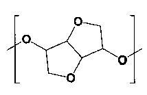
1つの実施形態においては、上記位相差フィルムは、Re(450)<Re(550)<Re(650)の関係を満たす。
1つの実施形態においては、上記位相差フィルムは、0.7<Re(450)/Re(550)<1.0の関係を満たす。
1つの実施形態においては、上記位相差フィルムのRe(550)は、100nm~180nmまたは220nm~330nmである。
円偏光板が提供される局面においては、この円偏光板は、上記位相差フィルムと、偏光子とを備える。
本発明の別の局面によれば、画像表示装置が提供される。この画像表示装置は、上記位相差フィルムを備える。別の実施形態においては、この画像表示装置は、上記円偏光板を備える。
本発明の別の局面によれば、上記位相差フィルムの製造方法が提供される。この製造方法は、ラジカル発生剤を用いて、上記樹脂と上記架橋剤とを、上記架橋剤の上記炭素―炭素二重結合を介して架橋させる工程を含む。
1つの実施形態においては、上記ラジカル発生剤は、水素引き抜き型光ラジカル発生剤である。
1つの実施形態においては、上記ラジカル発生剤は、水素引き抜き型熱ラジカル発生剤である。 The retardation film according to the embodiment of the present invention includes a first cured layer, a retardation layer, and a second cured layer in this order, and the retardation layer is formed of a stretched resin film. Contains a resin containing at least one bonding group selected from carbonate and ester bonds, with a cross-linking agent having a carbon-carbon double bond in the first cured layer and the second cured layer. The resin is crosslinked via the carbon-carbon double bond.
In one embodiment, the resin comprises a structural unit represented by the following formula.
In one embodiment, the resin comprises a structural unit represented by the following formula.
In one embodiment, the retardation film satisfies the relationship Re (450) <Re (550) <Re (650).
In one embodiment, the retardation film satisfies the relationship 0.7 <Re (450) / Re (550) <1.0.
In one embodiment, the Re (550) of the retardation film is 100 nm to 180 nm or 220 nm to 330 nm.
In the aspect where the circularly polarizing plate is provided, the circularly polarizing plate includes the above-mentioned retardation film and a polarizing element.
According to another aspect of the present invention, an image display device is provided. This image display device includes the retardation film. In another embodiment, the image display device comprises the circularly polarizing plate.
According to another aspect of the present invention, there is provided a method for manufacturing the above retardation film. This production method includes a step of cross-linking the resin and the cross-linking agent via the carbon-carbon double bond of the cross-linking agent using a radical generator.
In one embodiment, the radical generator is a hydrogen abstraction type photoradical generator.
In one embodiment, the radical generator is a hydrogen abstraction type thermal radical generator.
1つの実施形態においては、上記樹脂は、下記式で表される構造単位を含む。
1つの実施形態においては、上記位相差フィルムは、0.7<Re(450)/Re(550)<1.0の関係を満たす。
1つの実施形態においては、上記位相差フィルムのRe(550)は、100nm~180nmまたは220nm~330nmである。
円偏光板が提供される局面においては、この円偏光板は、上記位相差フィルムと、偏光子とを備える。
本発明の別の局面によれば、画像表示装置が提供される。この画像表示装置は、上記位相差フィルムを備える。別の実施形態においては、この画像表示装置は、上記円偏光板を備える。
本発明の別の局面によれば、上記位相差フィルムの製造方法が提供される。この製造方法は、ラジカル発生剤を用いて、上記樹脂と上記架橋剤とを、上記架橋剤の上記炭素―炭素二重結合を介して架橋させる工程を含む。
1つの実施形態においては、上記ラジカル発生剤は、水素引き抜き型光ラジカル発生剤である。
1つの実施形態においては、上記ラジカル発生剤は、水素引き抜き型熱ラジカル発生剤である。 The retardation film according to the embodiment of the present invention includes a first cured layer, a retardation layer, and a second cured layer in this order, and the retardation layer is formed of a stretched resin film. Contains a resin containing at least one bonding group selected from carbonate and ester bonds, with a cross-linking agent having a carbon-carbon double bond in the first cured layer and the second cured layer. The resin is crosslinked via the carbon-carbon double bond.
In one embodiment, the resin comprises a structural unit represented by the following formula.
In one embodiment, the retardation film satisfies the relationship 0.7 <Re (450) / Re (550) <1.0.
In one embodiment, the Re (550) of the retardation film is 100 nm to 180 nm or 220 nm to 330 nm.
In the aspect where the circularly polarizing plate is provided, the circularly polarizing plate includes the above-mentioned retardation film and a polarizing element.
According to another aspect of the present invention, an image display device is provided. This image display device includes the retardation film. In another embodiment, the image display device comprises the circularly polarizing plate.
According to another aspect of the present invention, there is provided a method for manufacturing the above retardation film. This production method includes a step of cross-linking the resin and the cross-linking agent via the carbon-carbon double bond of the cross-linking agent using a radical generator.
In one embodiment, the radical generator is a hydrogen abstraction type photoradical generator.
In one embodiment, the radical generator is a hydrogen abstraction type thermal radical generator.
本発明の実施形態による位相差フィルムは、第1の硬化層と位相差層と第2の硬化層とをこの順に備える。位相差層は延伸樹脂フィルムから形成されており、延伸樹脂フィルムは、カーボネート結合およびエステル結合から選択される少なくとも1種の結合基を含有する樹脂を含む。さらに、第1の硬化層および第2の硬化層においては、炭素―炭素二重結合を有する架橋剤と、延伸樹脂フィルムに含まれる樹脂とが、炭素―炭素二重結合を介して架橋している。本発明の実施形態による位相差フィルムにおいて、位相差層と、第1の硬化層および第2の硬化層とが、上記のように架橋していることにより、加熱環境下および加湿環境下においても位相差変化が小さく、さらに溶剤に接触した場合においても位相差変化が小さい、位相差フィルムを得ることができる。
The retardation film according to the embodiment of the present invention includes a first cured layer, a retardation layer, and a second cured layer in this order. The retardation layer is formed from a stretched resin film, which comprises a resin containing at least one binding group selected from carbonate and ester bonds. Further, in the first cured layer and the second cured layer, the cross-linking agent having a carbon-carbon double bond and the resin contained in the stretched resin film are cross-linked via the carbon-carbon double bond. There is. In the retardation film according to the embodiment of the present invention, the retardation layer and the first cured layer and the second cured layer are crosslinked as described above, so that even in a heating environment and a humidified environment. It is possible to obtain a retardation film having a small retardation change and a small retardation change even when in contact with a solvent.
以下、本発明の代表的な実施形態について説明するが、本発明はこれらの実施形態には限定されない。
Hereinafter, typical embodiments of the present invention will be described, but the present invention is not limited to these embodiments.
(用語および記号の定義)
本明細書における用語および記号の定義は下記の通りである。
(1)屈折率(nx、ny、nz)
「nx」は面内の屈折率が最大になる方向(すなわち、遅相軸方向)の屈折率であり、「ny」は面内で遅相軸と直交する方向(すなわち、進相軸方向)の屈折率であり、「nz」は厚み方向の屈折率である。
(2)面内位相差(Re)
「Re(λ)」は、23℃における波長λnmの光で測定した面内位相差である。例えば、「Re(550)」は、23℃における波長550nmの光で測定した面内位相差である。Re(λ)は、層(フィルム)の厚みをd(nm)としたとき、式:Re(λ)=(nx-ny)×dによって求められる。
(3)角度
本明細書において角度に言及するときは、当該角度は基準方向に対して時計回りおよび反時計回りの両方を包含する。したがって、例えば「45°」は±45°を意味する。 (Definition of terms and symbols)
Definitions of terms and symbols herein are as follows.
(1) Refractive index (nx, ny, nz)
"Nx" is the refractive index in the direction in which the refractive index in the plane is maximized (that is, the direction of the slow phase axis), and "ny" is the direction orthogonal to the slow phase axis in the plane (that is, the direction of the phase advance axis). Is the refractive index of, and "nz" is the refractive index in the thickness direction.
(2) In-plane phase difference (Re)
“Re (λ)” is an in-plane phase difference measured with light having a wavelength of λ nm at 23 ° C. For example, "Re (550)" is an in-plane phase difference measured with light having a wavelength of 550 nm at 23 ° C. Re (λ) is obtained by the formula: Re (λ) = (nx−ny) × d, where d (nm) is the thickness of the layer (film).
(3) Angle When referring to an angle herein, the angle includes both clockwise and counterclockwise with respect to the reference direction. Therefore, for example, "45 °" means ± 45 °.
A.位相差フィルムの全体構成
図1は、本発明の1つの実施形態による位相差フィルムの概略断面図である。図示例の位相差フィルム100は、第1の硬化層10と、位相差層20と、第2の硬化層30とをこの順に有する。位相差層は延伸樹脂フィルムから形成されており、該延伸樹脂フィルムは、カーボネート結合およびエステル結合から選択される少なくとも1種の結合基を含有する樹脂を含む。第1の硬化層および第2の硬化層においては、炭素―炭素二重結合を有する架橋剤と、延伸樹脂フィルムに含まれる樹脂とが、炭素―炭素二重結合を介して架橋している。その結果、位相差層の両側の表面近傍に第1の硬化層及び第2の硬化層が形成され得る。より詳細には、位相差フィルムにおいては、位相差層の厚み方向中央部は未架橋または架橋度合いの小さい上記樹脂で構成され、表面近傍の上記樹脂が架橋した結果、第1の硬化層および第2の硬化層が形成されていると推察される。すなわち、第1の硬化層および第2の硬化層は、位相差層に含まれる樹脂から形成される。位相差フィルムは、このような構造を有することにより、加熱環境下、加湿環境下および溶剤接触後の位相差変化が小さく、さらに耐溶剤性にも優れるという利点を有する。なお、図1は模式図であり、便宜上、第1の硬化層、延伸樹脂フィルムおよび第2の硬化層の界面が明確に示されている。しかし、実際は、明確な界面は存在せず、第1の硬化層、延伸樹脂フィルムおよび第2の硬化層はグラデーション構造を有している場合があり得ると推察される。 A. Overall Configuration of Phase Difference Film FIG. 1 is a schematic cross-sectional view of a retardation film according to one embodiment of the present invention. Theretardation film 100 of the illustrated example has a first cured layer 10, a retardation layer 20, and a second cured layer 30 in this order. The retardation layer is formed from a stretched resin film, the stretched resin film containing a resin containing at least one binding group selected from carbonate and ester bonds. In the first cured layer and the second cured layer, the cross-linking agent having a carbon-carbon double bond and the resin contained in the stretched resin film are cross-linked via the carbon-carbon double bond. As a result, the first cured layer and the second cured layer can be formed in the vicinity of the surfaces on both sides of the retardation layer. More specifically, in the retardation film, the central portion of the retardation layer in the thickness direction is composed of the above-mentioned resin which is not crosslinked or has a small degree of cross-linking, and as a result of the above-mentioned resin near the surface being crosslinked, the first cured layer and the first cured layer. It is presumed that the hardened layer of 2 is formed. That is, the first cured layer and the second cured layer are formed from the resin contained in the retardation layer. By having such a structure, the retardation film has an advantage that the phase difference change is small in a heating environment, a humidifying environment, and after contact with a solvent, and further, it is excellent in solvent resistance. Note that FIG. 1 is a schematic diagram, and for convenience, the interface between the first cured layer, the stretched resin film, and the second cured layer is clearly shown. However, in reality, there is no clear interface, and it is presumed that the first cured layer, the stretched resin film, and the second cured layer may have a gradation structure.
図1は、本発明の1つの実施形態による位相差フィルムの概略断面図である。図示例の位相差フィルム100は、第1の硬化層10と、位相差層20と、第2の硬化層30とをこの順に有する。位相差層は延伸樹脂フィルムから形成されており、該延伸樹脂フィルムは、カーボネート結合およびエステル結合から選択される少なくとも1種の結合基を含有する樹脂を含む。第1の硬化層および第2の硬化層においては、炭素―炭素二重結合を有する架橋剤と、延伸樹脂フィルムに含まれる樹脂とが、炭素―炭素二重結合を介して架橋している。その結果、位相差層の両側の表面近傍に第1の硬化層及び第2の硬化層が形成され得る。より詳細には、位相差フィルムにおいては、位相差層の厚み方向中央部は未架橋または架橋度合いの小さい上記樹脂で構成され、表面近傍の上記樹脂が架橋した結果、第1の硬化層および第2の硬化層が形成されていると推察される。すなわち、第1の硬化層および第2の硬化層は、位相差層に含まれる樹脂から形成される。位相差フィルムは、このような構造を有することにより、加熱環境下、加湿環境下および溶剤接触後の位相差変化が小さく、さらに耐溶剤性にも優れるという利点を有する。なお、図1は模式図であり、便宜上、第1の硬化層、延伸樹脂フィルムおよび第2の硬化層の界面が明確に示されている。しかし、実際は、明確な界面は存在せず、第1の硬化層、延伸樹脂フィルムおよび第2の硬化層はグラデーション構造を有している場合があり得ると推察される。 A. Overall Configuration of Phase Difference Film FIG. 1 is a schematic cross-sectional view of a retardation film according to one embodiment of the present invention. The
位相差フィルムのゲル分率は、好ましくは90%以上であり、より好ましくは95%以上であり、さらに好ましくは97%~99%である。このようなゲル分率は、第1の硬化層および第2の硬化層により位相差層への溶媒の侵入が実質的に防止されているために実現されると推察される。上記のとおり、位相差層の厚み方向中央部は未架橋または架橋度合いの小さい上記樹脂で構成されていると推察されるが、第1の硬化層および第2の硬化層により、ゲル分率には反映されない。なお、ゲル分率は、位相差フィルムから作製した試料を所定の溶媒(例えば、トルエン)に浸漬し、浸漬前後の試料の重量から算出され得る。
The gel fraction of the retardation film is preferably 90% or more, more preferably 95% or more, and further preferably 97% to 99%. It is presumed that such a gel fraction is realized because the first cured layer and the second cured layer substantially prevent the solvent from entering the retardation layer. As described above, it is presumed that the central portion of the retardation layer in the thickness direction is uncrosslinked or is composed of the above resin having a small degree of crosslinking. Is not reflected. The gel fraction can be calculated from the weight of the sample before and after immersing the sample prepared from the retardation film in a predetermined solvent (for example, toluene).
上記架橋は、1つの実施形態においては、位相差層に含まれる樹脂におけるイソソルビド系ジヒドロキシ化合物に由来する構造単位同士の架橋であり得る。さらに、1つの実施形態においては、第1の硬化層および第2の硬化層において、架橋剤と上記樹脂におけるイソソルビド系ジヒドロキシ化合物に由来する構造単位との炭素―炭素結合を介した架橋であり得る。例として、該イソソルビド系ジヒドロキシ化合物に由来する構造単位同士が、架橋剤の炭素―炭素二重結合を介して架橋した反応物の構造を下記に示す。さらに、該架橋反応に用いられる架橋剤の構造を下記に示す。


In one embodiment, the cross-linking may be cross-linking between structural units derived from the isosorbide-based dihydroxy compound in the resin contained in the retardation layer. Further, in one embodiment, the first cured layer and the second cured layer may be cross-linked via a carbon-carbon bond between the cross-linking agent and the structural unit derived from the isosorbide-based dihydroxy compound in the above resin. .. As an example, the structure of a reaction product in which structural units derived from the isosorbide dihydroxy compound are crosslinked via a carbon-carbon double bond of a crosslinking agent is shown below. Further, the structure of the cross-linking agent used in the cross-linking reaction is shown below.
このような架橋構造は、延伸樹脂フィルムを作製した後に架橋処理を行うことにより(後架橋により)形成され得る。1つの実施形態においては、延伸樹脂フィルムの両面に、架橋剤とラジカル発生剤とを含む反応性組成物を介してポリエチレンテレフタレート(PET)フィルムをロールラミネートする。得られた積層体に対して架橋反応を行い、さらにPETフィルムを剥離することで、延伸樹脂フィルム(位相差層)の表面に第1の硬化層および第2の硬化層が形成され、本発明の実施形態による位相差フィルムが得られる。別の実施形態においては、延伸樹脂フィルムの表面に、架橋剤とラジカル発生剤と(必要に応じて希釈溶剤と)を含む反応性組成物を塗布し、必要に応じて加熱処理を施した後、窒素雰囲気にて(熱またはUV照射により)架橋反応を行うことで、硬化層を得ることができる。この操作を延伸樹脂フィルムの両面に施すことで、延伸樹脂フィルム(位相差層)の表面に第1の硬化層および第2の硬化層が形成され、本発明の実施形態による位相差フィルムが得られる。このような架橋構造の形成においては、延伸樹脂フィルムを形成する樹脂が架橋性基を含む必要がない。架橋性基を含む樹脂を用いて延伸樹脂フィルムを製造する場合、製造工程(例えば、混練、押出、延伸)において、該樹脂がゲル化するなどの問題が発生し得る。本発明の実施形態によれば、このような問題を起こすことなく、第1の硬化層および第2の硬化層を有する位相差フィルムを製造することができる。さらに、本発明の実施形態による後架橋によれば、通常の位相差フィルムおよび当該位相差フィルムを製造する工程を改変することなく、本発明の実施形態による位相差フィルムの製造に供することができる。この点において、本願発明は優れた効果を有する。
Such a crosslinked structure can be formed (by post-crosslinking) by performing a crosslinking treatment after producing a stretched resin film. In one embodiment, a polyethylene terephthalate (PET) film is roll-laminated on both sides of a stretched resin film via a reactive composition containing a cross-linking agent and a radical generator. By performing a crosslinking reaction on the obtained laminate and further peeling off the PET film, a first cured layer and a second cured layer are formed on the surface of the stretched resin film (phase difference layer), and the present invention A retardation film according to the above embodiment can be obtained. In another embodiment, the surface of the stretched resin film is coated with a reactive composition containing a cross-linking agent, a radical generator (with a diluting solvent if necessary), and then heat-treated as necessary. A cured layer can be obtained by carrying out a cross-linking reaction (by heat or UV irradiation) in a nitrogen atmosphere. By applying this operation to both sides of the stretched resin film, a first cured layer and a second cured layer are formed on the surface of the stretched resin film (phase difference layer), and a retardation film according to the embodiment of the present invention is obtained. Be done. In forming such a crosslinked structure, the resin forming the stretched resin film does not need to contain a crosslinkable group. When a stretched resin film is manufactured using a resin containing a crosslinkable group, problems such as gelation of the resin may occur in the manufacturing process (for example, kneading, extrusion, stretching). According to the embodiment of the present invention, it is possible to manufacture a retardation film having a first cured layer and a second cured layer without causing such a problem. Further, according to the post-crosslinking according to the embodiment of the present invention, the retardation film can be produced according to the embodiment of the present invention without modifying the normal retardation film and the process for producing the retardation film. .. In this respect, the invention of the present application has an excellent effect.
位相差フィルム(実質的には、位相差層)は、好ましくはRe(450)<Re(550)<Re(650)の関係を満たす。さらに、位相差フィルムは、好ましくは0.7<Re(450)/Re(550)<1.0の関係を満たす。すなわち、位相差フィルムは、位相差値が測定光の波長に応じて大きくなる逆波長分散特性を示す。位相差フィルムがこのような特性を有することにより、非常に優れた反射防止特性が実現され得る。
The retardation film (substantially, the retardation layer) preferably satisfies the relationship of Re (450) <Re (550) <Re (650). Further, the retardation film preferably satisfies the relationship of 0.7 <Re (450) / Re (550) <1.0. That is, the retardation film exhibits a reverse wavelength dispersion characteristic in which the retardation value increases according to the wavelength of the measured light. When the retardation film has such characteristics, very excellent antireflection characteristics can be realized.
位相差フィルム(実質的には、位相差層)は、好ましくはRe(550)が100nm~180nmであり、または、220nm~330nmであり、より好ましくはRe(550)が120nm~180nmであり、または、240nm~310nmである。
The retardation film (substantially, the retardation layer) preferably has Re (550) of 100 nm to 180 nm or 220 nm to 330 nm, and more preferably Re (550) of 120 nm to 180 nm. Alternatively, it is 240 nm to 310 nm.
位相差フィルムの厚みは、所望のRe(550)に応じて、任意の適切な厚みが採用され得る。位相差フィルムの厚みは、好ましくは20μm~100μmであり、より好ましくは30μm~60μmである。該厚みとは、位相差層と、第1の硬化層および第2の硬化層との総厚みを示す。
As the thickness of the retardation film, any appropriate thickness can be adopted depending on the desired Re (550). The thickness of the retardation film is preferably 20 μm to 100 μm, more preferably 30 μm to 60 μm. The thickness indicates the total thickness of the retardation layer and the first cured layer and the second cured layer.
位相差フィルム(実質的には、位相差層)は、内部ヘイズが好ましくは3%以下であり、より好ましくは2%以下であり、さらに好ましくは1%以下である。内部ヘイズの下限は、実質的には0%であり得る。内部ヘイズがこのような範囲であれば、位相差フィルムの優れた透明性が実現され得る。
The retardation film (substantially, the retardation layer) has an internal haze of preferably 3% or less, more preferably 2% or less, still more preferably 1% or less. The lower limit of the internal haze can be substantially 0%. If the internal haze is in such a range, excellent transparency of the retardation film can be realized.
位相差フィルム(実質的には、位相差層)の光弾性係数は、好ましくは1×10-12(m2/N)~40×10-12(m2/N)であり、より好ましくは1×10-12(m2/N)~30×10-12(m2/N)でり、さらに好ましくは1×10-12(m2/N)~20×10-12(m2/N)である。
The photoelastic coefficient of the retardation film (substantially the retardation layer) is preferably 1 × 10 -12 (m 2 / N) to 40 × 10 -12 (m 2 / N), more preferably. 1 × 10 -12 (m 2 / N) ~ 30 × 10 -12 (m 2 / N) deli, more preferably 1 × 10 -12 (m 2 / N) ~ 20 × 10 -12 (m 2 / N).
A-1.位相差層
位相差層は、延伸樹脂フィルムから形成され得る。該延伸樹脂フィルムは、樹脂フィルムを延伸することにより得られ得る。該樹脂フィルムは、カーボネート結合とエステル結合の少なくとも1種の結合基を含有する樹脂を含む。該樹脂としては、例えば、ポリカーボネート系樹脂、ポリエステルカーボネート系樹脂、ポリエステル系樹脂、ポリアリレート系樹脂、アクリル系樹脂が挙げられる。これらの樹脂は、単独で用いてもよく組み合わせて(例えば、ブレンド、共重合)用いてもよい。これらの樹脂の中でも、ポリカーボネート系樹脂またはポリエステルカーボネート系樹脂(以下、単にポリカーボネート系樹脂と称する場合がある)が好適に用いられる。 A-1. Phase difference layer The retardation layer can be formed from a stretched resin film. The stretched resin film can be obtained by stretching the resin film. The resin film contains a resin containing at least one bonding group of carbonate bond and ester bond. Examples of the resin include a polycarbonate resin, a polyester carbonate resin, a polyester resin, a polyarylate resin, and an acrylic resin. These resins may be used alone or in combination (eg, blending, copolymerization). Among these resins, a polycarbonate-based resin or a polyester carbonate-based resin (hereinafter, may be simply referred to as a polycarbonate-based resin) is preferably used.
位相差層は、延伸樹脂フィルムから形成され得る。該延伸樹脂フィルムは、樹脂フィルムを延伸することにより得られ得る。該樹脂フィルムは、カーボネート結合とエステル結合の少なくとも1種の結合基を含有する樹脂を含む。該樹脂としては、例えば、ポリカーボネート系樹脂、ポリエステルカーボネート系樹脂、ポリエステル系樹脂、ポリアリレート系樹脂、アクリル系樹脂が挙げられる。これらの樹脂は、単独で用いてもよく組み合わせて(例えば、ブレンド、共重合)用いてもよい。これらの樹脂の中でも、ポリカーボネート系樹脂またはポリエステルカーボネート系樹脂(以下、単にポリカーボネート系樹脂と称する場合がある)が好適に用いられる。 A-1. Phase difference layer The retardation layer can be formed from a stretched resin film. The stretched resin film can be obtained by stretching the resin film. The resin film contains a resin containing at least one bonding group of carbonate bond and ester bond. Examples of the resin include a polycarbonate resin, a polyester carbonate resin, a polyester resin, a polyarylate resin, and an acrylic resin. These resins may be used alone or in combination (eg, blending, copolymerization). Among these resins, a polycarbonate-based resin or a polyester carbonate-based resin (hereinafter, may be simply referred to as a polycarbonate-based resin) is preferably used.
上記ポリカーボネート系樹脂としては、本発明の効果が得られる限りにおいて、任意の適切なポリカーボネート系樹脂を用いることができる。例えば、ポリカーボネート系樹脂は、好ましくは、フルオレン系ジヒドロキシ化合物に由来する構造単位と、イソソルビド系ジヒドロキシ化合物に由来する構造単位と、脂環式ジオール、脂環式ジメタノール、ジ、トリまたはポリエチレングリコール、ならびに、アルキレングリコールまたはスピログリコールからなる群から選択される少なくとも1つのジヒドロキシ化合物に由来する構造単位と、を含む。より好ましくは、ポリカーボネート系樹脂は、フルオレン系ジヒドロキシ化合物に由来する構造単位と、イソソルビド系ジヒドロキシ化合物に由来する構造単位と、脂環式ジメタノールに由来する構造単位ならびに/あるいはジ、トリまたはポリエチレングリコールに由来する構造単位と、を含み;さらに好ましくは、フルオレン系ジヒドロキシ化合物に由来する構造単位と、イソソルビド系ジヒドロキシ化合物に由来する構造単位と、ジ、トリまたはポリエチレングリコールに由来する構造単位と、を含む。ポリカーボネート系樹脂は、必要に応じてその他のジヒドロキシ化合物に由来する構造単位を含んでいてもよい。なお、本発明に好適に用いられ得るポリカーボネート系樹脂の詳細は、例えば、特開2014-10291号公報、特開2014-26266号公報、特開2015-212816号公報、特開2015-212817号公報、特開2015-212818号公報に記載されており、当該記載は本明細書に参考として援用される。
As the above-mentioned polycarbonate-based resin, any suitable polycarbonate-based resin can be used as long as the effects of the present invention can be obtained. For example, the polycarbonate-based resin preferably contains a structural unit derived from a fluorene-based dihydroxy compound, a structural unit derived from an isosorbide-based dihydroxy compound, and an alicyclic diol, an alicyclic dimethanol, di, tri or polyethylene glycol. Also included are structural units derived from at least one dihydroxy compound selected from the group consisting of alkylene glycols or spiroglycols. More preferably, the polycarbonate-based resin contains a structural unit derived from a fluorene-based dihydroxy compound, a structural unit derived from an isosorbide-based dihydroxy compound, a structural unit derived from an alicyclic dimethanol, and / or di, tri or polyethylene glycol. Containing structural units derived from; more preferably, structural units derived from fluorene-based dihydroxy compounds, structural units derived from isosorbide-based dihydroxy compounds, and structural units derived from di, tri or polyethylene glycol. include. The polycarbonate-based resin may contain structural units derived from other dihydroxy compounds, if necessary. Details of the polycarbonate-based resin that can be suitably used for the present invention are, for example, JP-A-2014-10291, JP-A-2014-226666, JP-A-2015-21816, JP-A-2015-21217. , Japanese Patent Application Laid-Open No. 2015-21218, and the description is incorporated herein by reference.
前記フルオレン系ジヒドロキシ化合物に由来する構造単位として、下記式で表される構造単位が挙げられる。当該構造単位をオリゴフルオレン構造単位ということがある。
Examples of the structural unit derived from the fluorene-based dihydroxy compound include structural units represented by the following formulas. The structural unit may be referred to as an oligofluorene structural unit.


前記一般式(1)及び前記一般式(2)中、R1~R3は、それぞれ独立に、直接結合、置換基を有していてもよい炭素数1~4のアルキレン基であり、R4~R9は、それぞれ独立に、水素原子、置換基を有していてもよい炭素数1~10のアルキル基、置換基を有していてもよい炭素数4~10のアリール基、置換基を有していてもよい炭素数1~10のアシル基、置換基を有していてもよい炭素数1~10のアルコキシ基、置換基を有していてもよい炭素数1~10のアリールオキシ基、置換基を有していてもよい炭素数1~10のアシルオキシ基、置換基を有していてもよいアミノ基、置換基を有していてもよい炭素数1~10のビニル基、置換基を有していてもよい炭素数1~10のエチニル基、置換基を有する硫黄原子、置換基を有するケイ素原子、ハロゲン原子、ニトロ基、又はシアノ基である。但し、R4~R9のうち隣接する少なくとも2つの基が互いに結合して環を形成していてもよい。また、前記一般式(1)に含まれる2つのR4、R5、R6、R7、R8及びR9は、互いに同一であっても、異なっていてもよい。同様に、前記一般式(2)に含まれる2つのR4、R5、R6、R7、R8及びR9は、互いに同一であっても、異なっていてもよい。
In the general formula (1) and the general formula (2), R 1 to R 3 are alkylene groups having 1 to 4 carbon atoms which may independently have a direct bond and a substituent, respectively, and are R. 4 to R 9 are each independently a hydrogen atom, an alkyl group having 1 to 10 carbon atoms which may have a substituent, an aryl group having 4 to 10 carbon atoms which may have a substituent, and a substituent. An acyl group having 1 to 10 carbon atoms which may have a group, an alkoxy group having 1 to 10 carbon atoms which may have a substituent, and 1 to 10 carbon atoms which may have a substituent. An aryloxy group, an acyloxy group having 1 to 10 carbon atoms which may have a substituent, an amino group which may have a substituent, and a vinyl having 1 to 10 carbon atoms which may have a substituent. A group, an ethynyl group having 1 to 10 carbon atoms which may have a substituent, a sulfur atom having a substituent, a silicon atom having a substituent, a halogen atom, a nitro group, or a cyano group. However, at least two adjacent groups of R 4 to R 9 may be bonded to each other to form a ring. Further, the two R 4 , R 5 , R 6 , R 7 , R 8 and R 9 included in the general formula (1) may be the same or different from each other. Similarly, the two R 4 , R 5 , R 6 , R 7 , R 8 and R 9 included in the general formula (2) may be the same as or different from each other.
R1及びR2において、「置換基を有していてもよい炭素数1~4のアルキレン基」としては、例えば以下のアルキレン基を採用することができる。メチレン基、エチレン基、n-プロピレン基、n-ブチレン基等の直鎖状のアルキレン基;メチルメチレン基、ジメチルメチレン基、エチルメチレン基、プロピルメチレン基、(1-メチルエチル)メチレン基、1-メチルエチレン基、2-メチルエチレン基、1-エチルエチレン基、2-エチルエチレン基、1-メチルプロピレン基、2-メチルプロピレン基、1,1-ジメチルエチレン基、2,2-ジメチルプロピレン基、3-メチルプロピレン基等の、分岐鎖を有するアルキレン基。ここで、R1及びR2における分岐鎖の位置は、フルオレン環側の炭素が1位となるように付与した番号により示した。
In R 1 and R 2 , for example, the following alkylene groups can be adopted as the "alkylene group having 1 to 4 carbon atoms which may have a substituent". Linear alkylene group such as methylene group, ethylene group, n-propylene group, n-butylene group; methylmethylene group, dimethylmethylene group, ethylmethylene group, propylmethylene group, (1-methylethyl) methylene group, 1 -Methylethylene group, 2-methylethylene group, 1-ethylethylene group, 2-ethylethylene group, 1-methylpropylene group, 2-methylpropylene group, 1,1-dimethylethylene group, 2,2-dimethylpropylene group , A alkylene group having a branched chain, such as a 3-methylpropylene group. Here, the positions of the branched chains in R 1 and R 2 are indicated by the numbers assigned so that the carbon on the fluorene ring side is at the 1st position.
R1及びR2の選択は、逆波長分散性の発現に特に重要な影響を及ぼす。前記樹脂は、フルオレン環が主鎖方向(延伸方向)に対して垂直に配向した状態において、最も強い逆波長分散性を示す。フルオレン環の配向状態を前記の状態に近づけ、強い逆波長分散性を発現させるためには、アルキレン基の主鎖上の炭素数が2~3であるR1及びR2を採用することが好ましい。炭素数が1の場合は意外にも逆波長分散性を示さない場合がある。この要因としては、オリゴフルオレン構造単位の連結基であるカーボネート基および/またはエステル基の立体障害によって、フルオレン環の配向が主鎖方向に対して垂直ではない方向に固定化されてしまうこと等が考えられる。一方、炭素数が多すぎる場合は、フルオレン環の配向の固定が弱くなることで、逆波長分散性が弱くなるおそれがある。また、樹脂の耐熱性も低下する。
The choice of R 1 and R 2 has a particularly important effect on the development of reverse wavelength dispersibility. The resin exhibits the strongest reverse wavelength dispersibility in a state where the fluorene ring is oriented perpendicular to the main chain direction (stretching direction). In order to bring the orientation state of the fluorene ring closer to the above state and to exhibit strong reverse wavelength dispersibility, it is preferable to adopt R 1 and R 2 having 2 to 3 carbon atoms on the main chain of the alkylene group. .. When the number of carbon atoms is 1, unexpectedly, the reverse wavelength dispersibility may not be exhibited. The reason for this is that the orientation of the fluorene ring is fixed in a direction that is not perpendicular to the main chain direction due to steric hindrance of the carbonate group and / or ester group that are the linking groups of the oligofluorene structural unit. Conceivable. On the other hand, when the number of carbon atoms is too large, the fixation of the orientation of the fluorene ring is weakened, which may weaken the reverse wavelength dispersibility. In addition, the heat resistance of the resin is also reduced.
前記一般式(1)及び一般式(2)に示すように、R1及びR2は、アルキレン基の一端がフルオレン環に結合し、他端が連結基に含まれる酸素原子またはカルボニル炭素のいずれかに結合している。熱安定性、耐熱性及び逆波長分散性の観点からは、アルキレン基の他端がカルボニル炭素に結合していることが好ましい。
As shown in the general formulas (1) and (2), in R 1 and R 2 , one end of the alkylene group is bonded to the fluorene ring and the other end is either an oxygen atom or a carbonyl carbon contained in the linking group. It is bound to the crab. From the viewpoint of thermal stability, heat resistance and reverse wavelength dispersibility, it is preferable that the other end of the alkylene group is bonded to the carbonyl carbon.
また、製造を容易にする観点からは、R1及びR2に同一のアルキレン基を採用することが好ましい。
Further, from the viewpoint of facilitating production, it is preferable to use the same alkylene group for R 1 and R 2.
R3において、「置換基を有していてもよい炭素数1~4のアルキレン基」としては、例えば以下のアルキレン基を採用することができる。メチレン基、エチレン基、n-プロピレン基、n-ブチレン基等の直鎖状のアルキレン基;メチルメチレン基、ジメチルメチレン基、エチルメチレン基、プロピルメチレン基、(1-メチルエチル)メチレン基、1-メチルエチレン基、2-メチルエチレン基、1-エチルエチレン基、2-エチルエチレン基、1-メチルプロピレン基、2-メチルプロピレン基、1,1-ジメチルエチレン基、2,2-ジメチルプロピレン基、3-メチルプロピレン基等の分岐鎖を有するアルキレン基。
In R 3, the term "alkylene group having 1 to carbon atoms which may have a substituent 4" may be employed for example, the following alkylene groups. Linear alkylene group such as methylene group, ethylene group, n-propylene group, n-butylene group; methylmethylene group, dimethylmethylene group, ethylmethylene group, propylmethylene group, (1-methylethyl) methylene group, 1 -Methylethylene group, 2-methylethylene group, 1-ethylethylene group, 2-ethylethylene group, 1-methylpropylene group, 2-methylpropylene group, 1,1-dimethylethylene group, 2,2-dimethylpropylene group , A alkylene group having a branched chain such as a 3-methylpropylene group.
R3は、アルキレン基の主鎖上の炭素数が1~2であることが好ましく、特に炭素数が1であることが好ましい。主鎖上の炭素数が多すぎるR3を採用する場合は、R1及びR2と同様にフルオレン環の固定化が弱まり、逆波長分散性の低下、光弾性係数の増加、耐熱性の低下等を招くおそれがある。一方、主鎖上の炭素数は少ない方が光学特性および/または耐熱性は良好であるが、二つのフルオレン環の9位が直接結合でつながる場合は熱安定性が悪化する。
R 3 preferably has 1 to 2 carbon atoms on the main chain of the alkylene group, and particularly preferably 1 carbon atom. When R 3 having too many carbon atoms on the main chain is adopted , the immobilization of the fluorene ring is weakened as in R 1 and R 2 , the reverse wavelength dispersibility is lowered, the photoelastic coefficient is increased, and the heat resistance is lowered. Etc. may be invited. On the other hand, the smaller the number of carbon atoms on the main chain, the better the optical properties and / or heat resistance, but when the 9-positions of the two fluorene rings are directly connected by a direct bond, the thermal stability deteriorates.
R1~R3において、アルキレン基が有していてもよい置換基としては、以下に例示する置換基を採用することができるが、これら以外の置換基を採用してもよい。フッ素原子、塩素原子、臭素原子及びヨウ素原子から選択されるハロゲン原子;メトキシ基、エトキシ基等の炭素数1~10のアルコキシ基;アセチル基、ベンゾイル基等の炭素数1~10のアシル基;アセトアミド基、ベンゾイルアミド基等の炭素数1~10のアシルアミノ基;ニトロ基;シアノ基;前記ハロゲン原子、前記アルコキシ基、前記アシル基、前記アシルアミノ基、前記ニトロ基、前記シアノ基等により1~3個の水素原子が置換されていてもよい、フェニル基、ナフチル基等の炭素数6~10のアリール基。
In R 1 to R 3 , the substituents exemplified below may be adopted as the substituents that the alkylene group may have, but substituents other than these may be adopted. Halogen atom selected from fluorine atom, chlorine atom, bromine atom and iodine atom; alkoxy group having 1 to 10 carbon atoms such as methoxy group and ethoxy group; acyl group having 1 to 10 carbon atoms such as acetyl group and benzoyl group; Acylamino groups having 1 to 10 carbon atoms such as acetoamide groups and benzoylamide groups; nitro groups; cyano groups; 1 to 1 to the halogen atoms, the alkoxy groups, the acyl groups, the acylamino groups, the nitro groups, the cyano groups and the like. An aryl group having 6 to 10 carbon atoms such as a phenyl group and a naphthyl group, wherein three hydrogen atoms may be substituted.
前記置換基の数は特に限定されないが、1~3個が好ましい。置換基が2個以上ある場合は、置換基の種類は同一でも異なっていてもよい。置換基の数が多すぎる場合には重合中に反応を阻害したり、熱分解したりするおそれがある。また、工業的に安価に製造できるとの観点からは、R1~R3が無置換であることが好ましい。
The number of the substituents is not particularly limited, but is preferably 1 to 3. When there are two or more substituents, the types of substituents may be the same or different. If the number of substituents is too large, the reaction may be inhibited or pyrolysis may occur during the polymerization. Further, from the viewpoint of industrially inexpensive production, it is preferable that R 1 to R 3 are unsubstituted.
R4~R9において、「置換基を有していてもよい炭素数1~10のアルキル基」としては、例えば以下のアルキル基を採用することができる。メチル基、エチル基、n-プロピル基、n-ブチル基、n-ペンチル基、n-ヘキシル、n-デシル等の直鎖状のアルキル基;イソプロピル基、2-メチルプロピル基、2,2-ジメチルプロピル基、2-エチルヘキシル基等の分岐鎖を有するアルキル基;シクロプロピル基、シクロペンチル基、シクロヘキシル基、シクロオクチル基等の環状のアルキル基。
In R 4 to R 9 , for example, the following alkyl groups can be adopted as the "alkyl group having 1 to 10 carbon atoms which may have a substituent". Linear alkyl groups such as methyl group, ethyl group, n-propyl group, n-butyl group, n-pentyl group, n-hexyl, n-decyl; isopropyl group, 2-methylpropyl group, 2,2- An alkyl group having a branched chain such as a dimethylpropyl group and a 2-ethylhexyl group; a cyclic alkyl group such as a cyclopropyl group, a cyclopentyl group, a cyclohexyl group and a cyclooctyl group.
前記アルキル基の炭素数は、4以下であることが好ましく、2以下であることがより好ましい。前記アルキル基の炭素数がこの範囲内であると、フルオレン環同士の立体障害が生じにくく、フルオレン環に由来する所望の光学特性が得られる傾向がある。
The number of carbon atoms of the alkyl group is preferably 4 or less, and more preferably 2 or less. When the number of carbon atoms of the alkyl group is within this range, steric hindrance between fluorene rings is unlikely to occur, and desired optical properties derived from the fluorene ring tend to be obtained.
前記アルキル基が有していてもよい置換基としては、以下に例示する置換基を採用することができるが、これら以外の置換基を採用してもよい。フッ素原子、塩素原子、臭素原子及びヨウ素原子から選択されるハロゲン原子;メトキシ基、エトキシ基等の炭素数1~10のアルコキシ基;アセチル基、ベンゾイル基等の炭素数1~10のアシル基;アセトアミド基、ベンゾイルアミド基等の炭素数1~10のアシルアミノ基;ニトロ基;シアノ基;前記ハロゲン原子、前記アルコキシ基、前記アシル基、前記アシルアミノ基、前記ニトロ基、前記シアノ基等により1~3個の水素原子が置換されていてもよい、フェニル基、ナフチル基等の炭素数6~10のアリール基。
As the substituent that the alkyl group may have, the substituents exemplified below can be adopted, but substituents other than these may be adopted. Halogen atom selected from fluorine atom, chlorine atom, bromine atom and iodine atom; alkoxy group having 1 to 10 carbon atoms such as methoxy group and ethoxy group; acyl group having 1 to 10 carbon atoms such as acetyl group and benzoyl group; Acylamino groups having 1 to 10 carbon atoms such as acetoamide groups and benzoylamide groups; nitro groups; cyano groups; 1 to 1 to the halogen atoms, the alkoxy groups, the acyl groups, the acylamino groups, the nitro groups, the cyano groups and the like. An aryl group having 6 to 10 carbon atoms such as a phenyl group and a naphthyl group, wherein three hydrogen atoms may be substituted.
前記置換基の数は特に限定されないが、1~3個が好ましい。置換基が2個以上ある場合は、置換基の種類は同一でも異なっていてもよい。このような置換基の数が多すぎる場合には重合中に反応を阻害したり、熱分解したりするおそれがある。また、工業的に安価に製造できるとの観点からは、R4~R9が無置換であることが好ましい。
The number of the substituents is not particularly limited, but is preferably 1 to 3. When there are two or more substituents, the types of substituents may be the same or different. If the number of such substituents is too large, the reaction may be inhibited or pyrolysis may occur during the polymerization. Further, from the viewpoint of industrially inexpensive production, it is preferable that R 4 to R 9 are unsubstituted.
前記アルキル基の具体例としては、トリフルオロメチル基、ベンジル基、4-メトキシベンジル基、メトキシメチル基等が挙げられる。
Specific examples of the alkyl group include a trifluoromethyl group, a benzyl group, a 4-methoxybenzyl group, a methoxymethyl group and the like.
また、R4~R9において、「置換基を有していてもよい炭素数4~10のアリール基」としては、例えば以下のアリール基を採用することができる。フェニル基、1-ナフチル基、2-ナフチル基等のアリール基;2-ピリジル基、2-チエニル基、2-フリル基等のヘテロアリール基。
Further, in R 4 to R 9 , for example, the following aryl group can be adopted as the "aryl group having 4 to 10 carbon atoms which may have a substituent". Aryl groups such as phenyl group, 1-naphthyl group and 2-naphthyl group; heteroaryl groups such as 2-pyridyl group, 2-thienyl group and 2-furyl group.
前記アリール基の炭素数は、8以下であることが好ましく、7以下であることがより好ましい。前記アリール基の炭素数がこの範囲内であると、フルオレン環同士の立体障害が生じにくく、フルオレン環に由来する所望の光学特性が得られる傾向がある。
The aryl group preferably has 8 or less carbon atoms, and more preferably 7 or less carbon atoms. When the number of carbon atoms of the aryl group is within this range, steric hindrance between the fluorene rings is unlikely to occur, and the desired optical properties derived from the fluorene ring tend to be obtained.
R4~R9において、前記アリール基が有していてもよい置換基としては、以下に例示する置換基を採用することができるが、これら以外の置換基を採用してもよい。フッ素原子、塩素原子、臭素原子及びヨウ素原子から選択されるハロゲン原子;メチル基、エチル基、イソプロピル基等の炭素数1~10のアルキル基;メトキシ基、エトキシ基等の炭素数1~10のアルコキシ基;アセチル基、ベンゾイル基等の炭素数1~10のアシル基;アセトアミド基、ベンゾイルアミド基等の炭素数1~10のアシルアミノ基;ニトロ基;シアノ基。前記置換基の数は特に限定されないが、1~3個が好ましい。置換基が2個以上ある場合は、置換基の種類は同一でも異なっていてもよい。また、工業的に安価に製造できるとの観点からは、R4~R9が無置換であることが好ましい。
In R 4 to R 9 , the substituents exemplified below may be adopted as the substituents that the aryl group may have, but substituents other than these may be adopted. Halogen atom selected from fluorine atom, chlorine atom, bromine atom and iodine atom; alkyl group having 1 to 10 carbon atoms such as methyl group, ethyl group and isopropyl group; Alkoxy group; acyl group having 1 to 10 carbon atoms such as acetyl group and benzoyl group; acylamino group having 1 to 10 carbon atoms such as acetamide group and benzoylamide group; nitro group; cyano group. The number of the substituents is not particularly limited, but is preferably 1 to 3. When there are two or more substituents, the types of substituents may be the same or different. Further, from the viewpoint of industrially inexpensive production, it is preferable that R 4 to R 9 are unsubstituted.
前記アリール基の具体例としては、2-メチルフェニル基、4-メチルフェニル基、3,5-ジメチルフェニル基、4-ベンゾイルフェニル基、4-メトキシフェニル基、4-ニトロフェニル基、4-シアノフェニル基、3-トリフルオロメチルフェニル基、3,4-ジメトキシフェニル基、3,4-メチレンジオキシフェニル基、2,3,4,5,6-ペンタフルオロフェニル基、4-メチルフリル基等が挙げられる。
Specific examples of the aryl group include 2-methylphenyl group, 4-methylphenyl group, 3,5-dimethylphenyl group, 4-benzoylphenyl group, 4-methoxyphenyl group, 4-nitrophenyl group and 4-cyano. Phenyl group, 3-trifluoromethylphenyl group, 3,4-dimethoxyphenyl group, 3,4-methylenedioxyphenyl group, 2,3,4,5,6-pentafluorophenyl group, 4-methylfuryl group, etc. Can be mentioned.
また、R4~R9において、「置換基を有していてもよい炭素数1~10のアシル基」としては、例えば以下のアシル基を採用することができる。ホルミル基、アセチル基、プロピオニル基、2-メチルプロピオニル基、2,2-ジメチルプロピオニル基、2-エチルヘキサノイル基等の脂肪族アシル基;ベンゾイル基、1-ナフチルカルボニル基、2-ナフチルカルボニル基、2-フリルカルボニル基等の芳香族アシル基。
Further, in R 4 - R 9, "acyl group which has ~ 1 carbon atoms which may 10 have a substituent" may be employed for example the following acyl groups. An aliphatic acyl group such as a formyl group, an acetyl group, a propionyl group, a 2-methylpropionyl group, a 2,2-dimethylpropionyl group and a 2-ethylhexanoyl group; a benzoyl group, a 1-naphthylcarbonyl group and a 2-naphthylcarbonyl group. , 2-Aromatic acyl groups such as frill carbonyl groups.
前記アシル基の炭素数は、4以下であることが好ましく、2以下であることがより好ましい。前記アシル基の炭素数がこの範囲内であると、フルオレン環同士の立体障害が生じにくく、フルオレン環に由来する所望の光学特性が得られる傾向がある。
The number of carbon atoms of the acyl group is preferably 4 or less, and more preferably 2 or less. When the number of carbon atoms of the acyl group is within this range, steric hindrance between the fluorene rings is unlikely to occur, and the desired optical properties derived from the fluorene ring tend to be obtained.
前記アシル基が有していてもよい置換基としては、以下に例示する置換基を採用することができるが、これら以外の置換基を採用してもよい。フッ素原子、塩素原子、臭素原子及びヨウ素原子から選択されるハロゲン原子;メチル基、エチル基、イソプロピル基等の炭素数1~10のアルキル基;メトキシ基、エトキシ基等の炭素数1~10のアルコキシ基;アセトアミド基、ベンゾイルアミド基等の炭素数1~10のアシルアミノ基;ニトロ基;シアノ基;前記ハロゲン原子、前記アルコキシ基、アセチル基、ベンゾイル基等の炭素数1~10のアシル基、前記アシルアミノ基、前記ニトロ基、前記シアノ基等により1~3個の水素原子が置換されていてもよい、フェニル基、ナフチル基等の炭素数6~10のアリール基。
As the substituent that the acyl group may have, the substituents exemplified below can be adopted, but substituents other than these may be adopted. Halogen atom selected from fluorine atom, chlorine atom, bromine atom and iodine atom; alkyl group having 1 to 10 carbon atoms such as methyl group, ethyl group and isopropyl group; Alkoxy group; acylamino group having 1 to 10 carbon atoms such as acetamide group and benzoylamide group; nitro group; cyano group; acyl group having 1 to 10 carbon atoms such as the halogen atom, the alkoxy group, the acetyl group and the benzoyl group. An aryl group having 6 to 10 carbon atoms such as a phenyl group and a naphthyl group, wherein 1 to 3 hydrogen atoms may be substituted with the acylamino group, the nitro group, the cyano group and the like.
前記置換基の数は特に限定されないが、1~3個が好ましい。置換基が2個以上ある場合は、置換基の種類は同一でも異なっていてもよい。また、工業的に安価に製造できるとの観点からは、R4~R9が無置換であることが好ましい。
The number of the substituents is not particularly limited, but is preferably 1 to 3. When there are two or more substituents, the types of substituents may be the same or different. Further, from the viewpoint of industrially inexpensive production, it is preferable that R 4 to R 9 are unsubstituted.
前記アシル基の具体例としては、クロロアセチル基、トリフルオロアセチル基、メトキシアセチル基、フェノキシアセチル基、4-メトキシベンゾイル基、4-ニトロベンゾイル基、4-シアノベンゾイル基、4-トリフルオロメチルベンソイル基等が挙げられる。
Specific examples of the acyl group include chloroacetyl group, trifluoroacetyl group, methoxyacetyl group, phenoxyacetyl group, 4-methoxybenzoyl group, 4-nitrobenzoyl group, 4-cyanobenzoyl group and 4-trifluoromethylben. Soil groups and the like can be mentioned.
また、R4~R9において、「置換基を有していてもよい炭素数1~10のアルコキシ基又はアリールオキシ基」としては、例えば以下のアルコキシ基及びアリールオキシ基を採用することができる。メトキシ基、エトキシ基、イソプロポキシ基、tert-ブトキシ基、トリフルオロメトキシ基、フェノキシ基等のアルコキシ基。
Further, in R 4 to R 9 , for example, the following alkoxy group and aryloxy group can be adopted as the "alkoxy group or aryloxy group having 1 to 10 carbon atoms which may have a substituent". .. Alkoxy groups such as methoxy group, ethoxy group, isopropoxy group, tert-butoxy group, trifluoromethoxy group and phenoxy group.
前記アルコキシ基及び前記アリールオキシ基の炭素数は、4以下であることが好ましく、2以下であることがより好ましい。前記アルコキシ基及び前記アリールオキシ基の炭素数がこの範囲内であると、フルオレン環同士の立体障害が生じにくく、フルオレン環に由来する所望の光学特性が得られる傾向がある。
The number of carbon atoms of the alkoxy group and the aryloxy group is preferably 4 or less, and more preferably 2 or less. When the carbon number of the alkoxy group and the aryloxy group is within this range, steric hindrance between the fluorene rings is unlikely to occur, and the desired optical properties derived from the fluorene ring tend to be obtained.
前記アルコキシ基及び前記アリールオキシ基が有していてもよい置換基としては、以下に例示する置換基を採用することができるが、これら以外の置換基を採用してもよい。フッ素原子、塩素原子、臭素原子及びヨウ素原子から選択されるハロゲン原子;メチル基、エチル基、イソプロピル基等の炭素数1~10のアルキル基;メトキシ基、エトキシ基等の炭素数1~10のアルコキシ基;アセトアミド基、ベンゾイルアミド基等の炭素数1~10のアシルアミノ基;ニトロ基;シアノ基; 前記ハロゲン原子、前記アルコキシ基、アセチル基、ベンゾイル基等の炭素数1~10のアシル基、前記アシルアミノ基、前記ニトロ基、前記シアノ基等により1~3個の水素原子が置換されていてもよい、フェニル基、ナフチル基等の炭素数6~10のアリール基。
As the substituents that the alkoxy group and the aryloxy group may have, the substituents exemplified below can be adopted, but substituents other than these may be adopted. Halogen atom selected from fluorine atom, chlorine atom, bromine atom and iodine atom; alkyl group having 1 to 10 carbon atoms such as methyl group, ethyl group and isopropyl group; Alkoxy group; acylamino group having 1 to 10 carbon atoms such as acetamide group and benzoylamide group; nitro group; cyano group; acyl group having 1 to 10 carbon atoms such as the halogen atom, the alkoxy group, the acetyl group and the benzoyl group. An aryl group having 6 to 10 carbon atoms such as a phenyl group and a naphthyl group, wherein 1 to 3 hydrogen atoms may be substituted with the acylamino group, the nitro group, the cyano group and the like.
前記置換基の数は特に限定されないが、1~3個が好ましい。置換基が2個以上ある場合は、置換基の種類は同一でも異なっていてもよい。また、工業的に安価に製造できるとの観点からは、R4~R9が無置換であることが好ましい。
The number of the substituents is not particularly limited, but is preferably 1 to 3. When there are two or more substituents, the types of substituents may be the same or different. Further, from the viewpoint of industrially inexpensive production, it is preferable that R 4 to R 9 are unsubstituted.
前記アルコキシ基及び前記アリールオキシ基の具体例としては、クロロメチル基、ブロモメチル基、2-ブロモエチル基、トリフルオロメチル基、メトキシメチル基、メトキシエトキシメチル基、3-クロロフェノキシ基、3-ブロモフェノキシ基、4-クロロフェノキシ基、3-クロロフェノキシ基、4-クロロフェノキシ基、3-ブロモフェノキシ基、4-ブロモフェノキシ基、4-メトキシフェノキシ基等が挙げられる。
Specific examples of the alkoxy group and the aryloxy group include chloromethyl group, bromomethyl group, 2-bromoethyl group, trifluoromethyl group, methoxymethyl group, methoxyethoxymethyl group, 3-chlorophenoxy group and 3-bromophenoxy. Examples thereof include a group, a 4-chlorophenoxy group, a 3-chlorophenoxy group, a 4-chlorophenoxy group, a 3-bromophenoxy group, a 4-bromophenoxy group, a 4-methoxyphenoxy group and the like.
また、R4~R9において、「置換基を有していてもよい炭素数1~10のアシルオキシ基」としては、例えば以下のアシルオキシ基を採用することができる。ホルミルオキシ基、アセチルオキシ基、プロパノイルオキシ基、ブタノイルオキシ基、アクリリルオキシ基、メタクリリルオキシ基等の脂肪族アシルオキシ基;ベンゾイルオキシ基等の芳香族アシルオキシ基。
Further, in R 4 to R 9 , for example, the following acyloxy groups can be adopted as the "acyloxy group having 1 to 10 carbon atoms which may have a substituent". An aliphatic acyloxy group such as a formyloxy group, an acetyloxy group, a propanoyloxy group, a butanoyloxy group, an acrylyloxy group and a methylenedioxy group; an aromatic acyloxy group such as a benzoyloxy group.
前記アシルオキシ基の炭素数は、4以下であることが好ましく、2以下であることがより好ましい。前記アシルオキシ基の炭素数がこの範囲内であると、フルオレン環同士の立体障害が生じにくく、フルオレン環に由来する所望の光学特性が得られる傾向がある。
The number of carbon atoms of the acyloxy group is preferably 4 or less, and more preferably 2 or less. When the number of carbon atoms of the acyloxy group is within this range, steric hindrance between the fluorene rings is unlikely to occur, and the desired optical properties derived from the fluorene ring tend to be obtained.
前記アシルオキシ基が有していてもよい置換基としては、以下に例示する置換基を採用することができるが、これら以外の置換基を採用してもよい。フッ素原子、塩素原子、臭素原子及びヨウ素原子から選択されるハロゲン原子;メチル基、エチル基、イソプロピル基等の炭素数1~10のアルキル基;メトキシ基、エトキシ基等の炭素数1~10のアルコキシ基;アセトアミド基、ベンゾイルアミド基等の炭素数1~10のアシルアミノ基;ニトロ基;シアノ基;前記ハロゲン原子、前記アルコキシ基、アセチル基、ベンゾイル基等の炭素数1~10のアシル基、前記アシルアミノ基、前記ニトロ基、前記シアノ基等により1~3個の水素原子が置換されていてもよい、フェニル基、ナフチル基等の炭素数6~10のアリール基。
As the substituent that the acyloxy group may have, the substituents exemplified below can be adopted, but substituents other than these may be adopted. Halogen atom selected from fluorine atom, chlorine atom, bromine atom and iodine atom; alkyl group having 1 to 10 carbon atoms such as methyl group, ethyl group and isopropyl group; Alkoxy group; acylamino group having 1 to 10 carbon atoms such as acetamide group and benzoylamide group; nitro group; cyano group; acyl group having 1 to 10 carbon atoms such as the halogen atom, the alkoxy group, the acetyl group and the benzoyl group. An aryl group having 6 to 10 carbon atoms such as a phenyl group and a naphthyl group, wherein 1 to 3 hydrogen atoms may be substituted with the acylamino group, the nitro group, the cyano group and the like.
前記置換基の数は特に限定されないが、1~3個が好ましい。置換基が2個以上ある場合は、置換基の種類は同一でも異なっていてもよい。また、工業的に安価に製造できるとの観点からは、R4~R9が無置換であることが好ましい。
The number of the substituents is not particularly limited, but is preferably 1 to 3. When there are two or more substituents, the types of substituents may be the same or different. Further, from the viewpoint of industrially inexpensive production, it is preferable that R 4 to R 9 are unsubstituted.
前記アシルオキシ基の具体例としては、クロロアセチルオキシ基、トリフルオロアセチルオキシ基、メトキシアセチルオキシ基、フェノキシアセチルオキシ基、4-メトキシベンゾイルオキシ基、4-ニトロベンゾイルオキシ基、4-シアノベンゾイルオキシ基、4-トリフルオロメチルベンソイルオキシ基等が挙げられる。
Specific examples of the acyloxy group include a chloroacetyloxy group, a trifluoroacetyloxy group, a methoxyacetyloxy group, a phenoxyacetyloxy group, a 4-methoxybenzoyloxy group, a 4-nitrobenzoyloxy group, and a 4-cyanobenzoyloxy group. , 4-Trifluoromethylbenzyloxy group and the like.
また、R4~R9において、「置換基を有していてもよいアミノ基」の具体的な構造としては、例えば以下のアミノ基を採用することができるが、これら以外のアミノ基を採用することも可能である。アミノ基;N-メチルアミノ基、N,N-ジメチルアミノ基、N-エチルアミノ基、N,N-ジエチルアミノ基、N,N-メチルエチルアミノ基、N-プロピルアミノ基、N,N-ジプロピルアミノ基、N-イソプロピルアミノ基、N,N-ジイソプロピルアミノ基等の脂肪族アミノ基;N-フェニルアミノ基、N,N-ジフェニルアミノ基等の芳香族アミノ基;ホルムアミド基、アセトアミド基、デカノイルアミド基、ベンゾイルアミド基、クロロアセトアミド基等のアシルアミノ基;ベンジルオキシカルボニルアミノ基、tert-ブチルオキシカルボニルアミノ基等のアルコキシカルボニルアミノ基。
Further, in R 4 to R 9 , for example, the following amino groups can be adopted as the specific structure of the "amino group which may have a substituent", but other amino groups are adopted. It is also possible to do. Amino group; N-methylamino group, N, N-dimethylamino group, N-ethylamino group, N, N-diethylamino group, N, N-methylethylamino group, N-propylamino group, N, N-di An aliphatic amino group such as a propylamino group, an N-isopropylamino group, an N, N-diisopropylamino group; an aromatic amino group such as an N-phenylamino group, an N, N-diphenylamino group; a formamide group, an acetamide group, Acylamino groups such as decanoylamide group, benzoylamide group and chloroacetamide group; alkoxycarbonylamino group such as benzyloxycarbonylamino group and tert-butyloxycarbonylamino group.
前記アミノ基としては、酸性度の高いプロトンを持たず、分子量が小さく、フルオレン比率を高めることができる傾向を有する、N,N-ジメチルアミノ基、N-エチルアミノ基、又はN,N-ジエチルアミノ基を採用することが好ましく、N,N-ジメチルアミノ基を採用することがより好ましい。
The amino group is an N, N-dimethylamino group, an N-ethylamino group, or an N, N-diethylamino group, which does not have a highly acidic proton, has a small molecular weight, and tends to increase the fluorene ratio. It is preferable to adopt a group, and it is more preferable to adopt an N, N-dimethylamino group.
また、R4~R9において、「置換基を有していてもよい炭素数1~10のビニル基又はエチニル基」としては、例えば以下のビニル基及びエチニル基を採用することができるが、これら以外のビニル基等を採用することも可能である。ビニル基、2-メチルビニル基、2,2-ジメチルビニル基、2-フェニルビニル基、2-アセチルビニル基、エチニル基、メチルエチニル基、tert-ブチルエチニル基、フェニルエチニル基、アセチルエチニル基、トリメチルシリルエチニル基。
Further, in R 4 to R 9 , for example, the following vinyl group and ethynyl group can be adopted as the "vinyl group or ethynyl group having 1 to 10 carbon atoms which may have a substituent". It is also possible to adopt a vinyl group or the like other than these. Vinyl group, 2-methylvinyl group, 2,2-dimethylvinyl group, 2-phenylvinyl group, 2-acetylvinyl group, ethynyl group, methylethynyl group, tert-butylethynyl group, phenylethynyl group, acetylethynyl group, Trimethylsilylethynyl group.
前記ビニル基及び前記エチニル基の炭素数は、4以下であることが好ましい。前記ビニル基及び前記エチニル基の炭素数がこの範囲内であると、フルオレン環同士の立体障害が生じにくく、フルオレン環に由来する所望の光学特性が得られる傾向がある。また、フルオレン環の共役系が長くなることにより、より強い逆波長分散性を得やすくなる。
The carbon number of the vinyl group and the ethynyl group is preferably 4 or less. When the carbon number of the vinyl group and the ethynyl group is within this range, steric hindrance between the fluorene rings is unlikely to occur, and the desired optical properties derived from the fluorene ring tend to be obtained. In addition, the longer the conjugated system of the fluorene ring makes it easier to obtain stronger inverse wavelength dispersibility.
また、R4~R9において「置換基を有する硫黄原子」としては、例えば以下の硫黄含有基を採用することができるが、これら以外の硫黄含有基を採用することも可能である。スルホ基;メチルスルホニル基、エチルスルホニル基、プロピルスルホニル基、イソプロピルスルホニル基等のアルキルスルホニル基;フェニルスルホニル基、p-トリルスルホニル基等のアリールスルホニル基;メチルスルフィニル基、エチルスルフィニル基、プロピルスルフィニル基、イソプロピルスルフィニル基等のアルキルスルフィニル基;フェニルスルフィニル基、p-トリルスルフィニル基等のアリールスルフィニル基;メチルチオ基、エチルチオ基等のアルキルチオ基;フェニルチオ基、p-トリルチオ基等のアリールチオ基;メトキシスルホニル基、エトキシスルホニル基等のアルコキシスルホニル基;フェノキシスルホニル基等のアリールオキシスルホニル基;アミノスルホニル基;N-メチルアミノスルホニル基、N-エチルアミノスルホニル基、N-tert-ブチルアミノス
ルホニル基、N,N-ジメチルアミノスルホニル基、N,N-ジエチルアミノスルホニル基等のアルキルスルホニル基;N-フェニルアミノスルホニル基、N,N-ジフェニルアミノスルホニル基等のアリールアミノスルホニル基。尚、スルホ基は、リチウム、ナトリウム、カリウム、マグネシウム、アンモニウム等と塩を形成していてもよい。 Further, as the "sulfur atom having a substituent" in R 4 to R 9 , for example, the following sulfur-containing groups can be adopted, but sulfur-containing groups other than these can also be adopted. Sulfonyl group; Alkylsulfonyl group such as methylsulfonyl group, ethylsulfonyl group, propylsulfonyl group, isopropylsulfonyl group; arylsulfonyl group such as phenylsulfonyl group, p-tolylsulfonyl group; methylsulfinyl group, ethylsulfinyl group, propylsulfinyl group Alkylsulfinyl groups such as isopropylsulfinyl group; arylsulfinyl groups such as phenylsulfinyl group and p-tolylsulfonyl group; alkylthio groups such as methylthio group and ethylthio group; arylthio groups such as phenylthio group and p-tolylthio group; methoxysulfonyl group , Ekoxysulfonyl groups such as ethoxysulfonyl groups; aryloxysulfonyl groups such as phenoxysulfonyl groups; aminosulfonyl groups; N-methylaminosulfonyl groups, N-ethylaminosulfonyl groups, N-tert-butylaminosulfonyl groups, N, N -Alkyl sulfonyl groups such as dimethylaminosulfonyl groups and N, N-diethylaminosulfonyl groups; arylaminosulfonyl groups such as N-phenylaminosulfonyl groups and N, N-diphenylaminosulfonyl groups. The sulfo group may form a salt with lithium, sodium, potassium, magnesium, ammonium or the like.
ルホニル基、N,N-ジメチルアミノスルホニル基、N,N-ジエチルアミノスルホニル基等のアルキルスルホニル基;N-フェニルアミノスルホニル基、N,N-ジフェニルアミノスルホニル基等のアリールアミノスルホニル基。尚、スルホ基は、リチウム、ナトリウム、カリウム、マグネシウム、アンモニウム等と塩を形成していてもよい。 Further, as the "sulfur atom having a substituent" in R 4 to R 9 , for example, the following sulfur-containing groups can be adopted, but sulfur-containing groups other than these can also be adopted. Sulfonyl group; Alkylsulfonyl group such as methylsulfonyl group, ethylsulfonyl group, propylsulfonyl group, isopropylsulfonyl group; arylsulfonyl group such as phenylsulfonyl group, p-tolylsulfonyl group; methylsulfinyl group, ethylsulfinyl group, propylsulfinyl group Alkylsulfinyl groups such as isopropylsulfinyl group; arylsulfinyl groups such as phenylsulfinyl group and p-tolylsulfonyl group; alkylthio groups such as methylthio group and ethylthio group; arylthio groups such as phenylthio group and p-tolylthio group; methoxysulfonyl group , Ekoxysulfonyl groups such as ethoxysulfonyl groups; aryloxysulfonyl groups such as phenoxysulfonyl groups; aminosulfonyl groups; N-methylaminosulfonyl groups, N-ethylaminosulfonyl groups, N-tert-butylaminosulfonyl groups, N, N -Alkyl sulfonyl groups such as dimethylaminosulfonyl groups and N, N-diethylaminosulfonyl groups; arylaminosulfonyl groups such as N-phenylaminosulfonyl groups and N, N-diphenylaminosulfonyl groups. The sulfo group may form a salt with lithium, sodium, potassium, magnesium, ammonium or the like.
前記硫黄含有基の中でも、酸性度の高いプロトンを持たず、分子量が小さく、フルオレン比率を高めることができる、メチルスルフィニル基、エチルスルフィニル基、又はフェニルスルフィニル基を採用することが好ましく、メチルスルフィニル基を採用することがより好ましい。
Among the sulfur-containing groups, it is preferable to use a methylsulfinyl group, an ethylsulfinyl group, or a phenylsulfinyl group, which does not have a highly acidic proton, has a small molecular weight, and can increase the fluorene ratio, and is preferably a methylsulfinyl group. It is more preferable to adopt.
また、R4~R9において、「置換基を有するケイ素原子」としては、例えば以下のシリル基を採用することができる。トリメチルシリル基、トリエチルシリル基等のトリアルキルシリル基;トリメトキシシリル基、トリエトキシシリル基等のトリアルコキシシリル基。これらの中でも安定に扱えるトリアルキルシリル基が好ましい。
Further, in R 4 to R 9 , for example, the following silyl group can be adopted as the "silicon atom having a substituent". Trialkylsilyl group such as trimethylsilyl group and triethylsilyl group; trialkoxysilyl group such as trimethoxysilyl group and triethoxysilyl group. Among these, a trialkylsilyl group that can be handled stably is preferable.
また、R4~R9において、「ハロゲン原子」としては、フッ素原子、塩素原子、臭素原子、ヨウ素原子を採用することができる。これらの中でも、比較的導入が容易であり、かつ、電子吸引性を有するためにフルオレン9位の反応性を高める傾向を有する、フッ素原子、塩素原子、又は臭素原子を採用することが好ましく、塩素原子又は臭素原子を採用することがより好ましい。
Further, in R 4 to R 9 , a fluorine atom, a chlorine atom, a bromine atom and an iodine atom can be adopted as the "halogen atom". Among these, it is preferable to use a fluorine atom, a chlorine atom, or a bromine atom, which is relatively easy to introduce and has a tendency to increase the reactivity at the 9-position of fluorene because of its electron-withdrawing property, and chlorine. It is more preferable to adopt an atom or a bromine atom.
前記イソソルビド系ジヒドロキシ化合物に由来する構造単位として、下記式で表される構造単位が挙げられる。

Examples of the structural unit derived from the isosorbide-based dihydroxy compound include structural units represented by the following formulas.
前記一般式(3)で表される構造単位を導入可能なジヒドロキシ化合物としては、立体異性体の関係にある、イソソルビド(ISB)、イソマンニド、イソイデットが挙げられる。これらは1種を単独で用いてもよく、2種以上を組み合わせて用いてもよい。これらの中でも、入手及び重合反応性の観点からISBを用いるのが最も好ましい。
Examples of the dihydroxy compound into which the structural unit represented by the general formula (3) can be introduced include isosorbide (ISB), isomannide, and isoidet having a stereoisomer relationship. These may be used individually by 1 type and may be used in combination of 2 or more type. Among these, ISB is most preferable from the viewpoint of availability and polymerization reactivity.
前記一般式(3)で表される構造単位は、前記樹脂中に5質量%以上、70質量%以下含有されていることが好ましく、10質量%以上、65質量%以下含有されていることがさらに好ましく、20質量%以上、60質量%以下含有されていることが特に好ましい。前記一般式(3)で表される構造単位の含有量が少なすぎると、耐熱性が不十分となるおそれがある。一方、前記一般式(3)で表される構造単位の含有量が多すぎると耐熱性が過度に高くなり、機械特性および/または溶融加工性が悪化する。
The structural unit represented by the general formula (3) is preferably contained in the resin in an amount of 5% by mass or more and 70% by mass or less, and preferably 10% by mass or more and 65% by mass or less. It is more preferable, and it is particularly preferable that the content is 20% by mass or more and 60% by mass or less. If the content of the structural unit represented by the general formula (3) is too small, the heat resistance may be insufficient. On the other hand, if the content of the structural unit represented by the general formula (3) is too large, the heat resistance becomes excessively high, and the mechanical properties and / or the melt processability deteriorate.
ジ、トリまたはポリエチレングリコールに由来する構造単位として、芳香族成分を含有しない下記一般式(4)~(8)で表される構造単位が挙げられる。
Examples of the structural unit derived from di, bird or polyethylene glycol include structural units represented by the following general formulas (4) to (8) that do not contain an aromatic component.

前記一般式(4)中、R10は置換基を有していてもよい炭素数2~20のアルキレン基を示す。
In the general formula (4), R 10 represents an alkylene group having 2 to 20 carbon atoms which may have a substituent.
前記一般式(4)の構造単位を導入可能なジヒドロキシ化合物としては、例えば、以下のジヒドロキシ化合物を採用することができる。エチレングリコール、1,3-プロパンジオール、1,2-プロパンジオール、1,4-ブタンジオール、1,3-ブタンジオール、1,2-ブタンジオール、1,5-ヘプタンジオール、1,6-ヘキサンジオール、1,9-ノナンジオール、1,10-デカンジオール、1,12-ドデカンジオール等の直鎖脂肪族炭化水素のジヒドロキシ化合物;ネオペンチルグリコール、ヘキシレングリコール等の分岐脂肪族炭化水素のジヒドロキシ化合物。
As the dihydroxy compound into which the structural unit of the general formula (4) can be introduced, for example, the following dihydroxy compound can be adopted. Ethylene glycol, 1,3-propanediol, 1,2-propanediol, 1,4-butanediol, 1,3-butanediol, 1,2-butanediol, 1,5-heptanediol, 1,6-hexane Dihydroxy compounds of linear aliphatic hydrocarbons such as diol, 1,9-nonanediol, 1,10-decanediol and 1,12-dodecanediol; dihydroxy of branched aliphatic hydrocarbons such as neopentyl glycol and hexylene glycol. Compound.

前記一般式(5)中、R11は置換基を有していてもよい炭素数4~20のシクロアルキレン基を示す。
In the general formula (5), R 11 represents a cycloalkylene group having 4 to 20 carbon atoms which may have a substituent.
前記一般式(5)の構造単位を導入可能なジヒドロキシ化合物としては、例えば、以下のジヒドロキシ化合物を採用することができる。1,2-シクロヘキサンジオール、1,4-シクロヘキサンジオール、1,3-アダマンタンジオール、水添ビスフェノールA、2,2,4,4-テトラメチル-1,3-シクロブタンジオール等に例示される、脂環式炭化水素の2級アルコール及び3級アルコールであるジヒドロキシ化合物。
As the dihydroxy compound into which the structural unit of the general formula (5) can be introduced, for example, the following dihydroxy compound can be adopted. Fats exemplified by 1,2-cyclohexanediol, 1,4-cyclohexanediol, 1,3-adamantandiol, hydrogenated bisphenol A, 2,2,4,4-tetramethyl-1,3-cyclobutanediol and the like. A dihydroxy compound which is a secondary alcohol and a tertiary alcohol of a cyclic hydrocarbon.

前記一般式(6)中、R12は置換基を有していてもよい炭素数4~20のシクロアルキレン基を示す。
In the general formula (6), R 12 represents a cycloalkylene group having 4 to 20 carbon atoms which may have a substituent.
前記一般式(6)の構造単位を導入可能なジヒドロキシ化合物としては、例えば、以下のジヒドロキシ化合物を採用することができる。1,2-シクロヘキサンジメタノール、1,3-シクロヘキサンジメタノール、1,4-シクロヘキサンジメタノール、トリシクロデカンジメタノール、ペンタシクロペンタデカンジメタノール、2,6-デカリンジメタノール、1,5-デカリンジメタノール、2,3-デカリンジメタノール、2,3-ノルボルナンジメタノール、2,5-ノルボルナンジメタノール、1,3-アダマンタンジメタノール、リモネン等の、テルペン化合物から誘導されるジヒドロキシ化合物等に例示される、脂環式炭化水素の1級アルコールであるジヒドロキシ化合物。
As the dihydroxy compound into which the structural unit of the general formula (6) can be introduced, for example, the following dihydroxy compound can be adopted. 1,2-Cyclohexanedimethanol, 1,3-Cyclohexanedimethanol, 1,4-Cyclohexanedimethanol, Tricyclodecanedimethanol, Pentacyclopentadecanedimethanol, 2,6-decalindimethanol, 1,5-decalingi It is exemplified by dihydroxy compounds derived from terpene compounds such as methanol, 2,3-decalindimethanol, 2,3-norbornandimethanol, 2,5-norbornandimethanol, 1,3-adamantandimethanol, limonene and the like. A dihydroxy compound that is a primary alcohol of alicyclic hydrocarbon.

前記一般式(7)中、R13は置換基を有していてもよい炭素数2~10のアルキレン基を示し、pは1~40の整数である。2以上あるR13は互いに同一であっても、異なっていてもよい。
In the general formula (7), R 13 represents an alkylene group having 2 to 10 carbon atoms which may have a substituent, and p is an integer of 1 to 40. Two or more R 13s may be the same or different from each other.
前記一般式(7)の構造単位を導入可能なジヒドロキシ化合物としては、例えば、以下のジヒドロキシ化合物を採用することができる。ジエチレングリコール、トリエチレングリコール、テトラエチレングリコール、ポリエチレングリコール、ポリプロピレングリコール等のオキシアルキレングリコール類。
As the dihydroxy compound into which the structural unit of the general formula (7) can be introduced, for example, the following dihydroxy compound can be adopted. Oxyalkylene glycols such as diethylene glycol, triethylene glycol, tetraethylene glycol, polyethylene glycol and polypropylene glycol.

前記一般式(8)中、R14は置換基を有していてもよい炭素数2~20のアセタール環を有する基を示す。
In the general formula (8), R 14 represents a group having an acetal ring having 2 to 20 carbon atoms which may have a substituent.
前記一般式(8)の構造単位を導入可能なジヒドロキシ化合物としては、例えば、下記構造式(14)で表されるスピログリコールまたは下記構造式(15)で表されるジオキサングリコール等を採用することができる。
As the dihydroxy compound into which the structural unit of the general formula (8) can be introduced, for example, spiroglycol represented by the following structural formula (14), dioxane glycol represented by the following structural formula (15), or the like is adopted. Can be done.


ポリカーボネート樹脂の詳細は、例えば特開2015-212816号公報、特開2010-134232号公報および特開2020-064298号公報に記載されている。当該特許文献の記載は、本明細書に参考として援用される。
Details of the polycarbonate resin are described in, for example, JP-A-2015-212816, JP-A-2010-134232 and JP-A-2020-064298. The description of the patent document is incorporated herein by reference.
A-2.第1の硬化層および第2の硬化層
第1の硬化層および第2の硬化層は、上記のように、位相差層に含まれる樹脂と架橋剤との架橋により形成され得る。したがって、第1の硬化層および第2の硬化層は、実質的には、架橋剤を介して架橋した上記樹脂で構成され得る。本発明の実施形態による位相差フィルムは、位相差層の両面に第1の硬化層および第2の硬化層を有することにより、加熱環境下、加湿環境下および溶剤接触後の位相差変化が小さく、さらに耐溶剤性にも優れるという利点を有する。 A-2. First Hardened Layer and Second Hardened Layer The first hardened layer and the second hardened layer can be formed by cross-linking the resin contained in the retardation layer and a cross-linking agent as described above. Therefore, the first cured layer and the second cured layer may be substantially composed of the above resin crosslinked via a crosslinking agent. The retardation film according to the embodiment of the present invention has a first cured layer and a second cured layer on both sides of the retardation layer, so that the retardation change is small under a heating environment, a humidifying environment, and after contact with a solvent. Further, it has the advantage of being excellent in solvent resistance.
第1の硬化層および第2の硬化層は、上記のように、位相差層に含まれる樹脂と架橋剤との架橋により形成され得る。したがって、第1の硬化層および第2の硬化層は、実質的には、架橋剤を介して架橋した上記樹脂で構成され得る。本発明の実施形態による位相差フィルムは、位相差層の両面に第1の硬化層および第2の硬化層を有することにより、加熱環境下、加湿環境下および溶剤接触後の位相差変化が小さく、さらに耐溶剤性にも優れるという利点を有する。 A-2. First Hardened Layer and Second Hardened Layer The first hardened layer and the second hardened layer can be formed by cross-linking the resin contained in the retardation layer and a cross-linking agent as described above. Therefore, the first cured layer and the second cured layer may be substantially composed of the above resin crosslinked via a crosslinking agent. The retardation film according to the embodiment of the present invention has a first cured layer and a second cured layer on both sides of the retardation layer, so that the retardation change is small under a heating environment, a humidifying environment, and after contact with a solvent. Further, it has the advantage of being excellent in solvent resistance.
該架橋剤としては、例えば、トリプロピレングリコールジ(メタ)アクリレート、テトラエチレングリコールジ(メタ)アクリレート、1,6-ヘキサンジオールジ(メタ)アクリレート、1,9-ノナンジオールジ(メタ)アクリレート、1,10-デカンジオールジ(メタ)アクリレート、2-エチル-2-ブチルプロパンジオールジ(メタ)アクリレート、ビスフェノールAジ(メタ)アクリレート、ビスフェノールAエチレンオキサイド付加物ジ(メタ)アクリレート、ビスフェノールAプロピレンオキサイド付加物ジ(メタ)アクリレート、ビスフェノールAジグリシジルエーテルジ(メタ)アクリレート、ネオぺンチルグリコールジ(メタ)アクリレート、トリシクロデカンジメタノールジ(メタ)アクリート、ジオキサングリコールジ(メタ)アクリレート、ポリエチレングリコールジ(メタ)アクリレート、ジプロピレングリコールジ(メタ)アクリレート、トリプロピレングリコールジ(メタ)アクリレート、ポリプロピレングリコールジ(メタ)アクリレート、トリメチロールプロパントリ(メタ)アクリレート、ペンタエリスリトールトリ(メタ)アクリレート、ペンタエリスリトールテトラ(メタ)アクリレート、ジペンタエリスリトールペンタ(メタ)アクリレート、ジペンタエリスリトールヘキサ(メタ)アクリレート、EO変性ジグリセリンテトラ(メタ)アクリレート等の(メタ)アクリル酸と多価アルコールとのエステル化物、9,9-ビス[4-(2-(メタ)アクリロイルオキシエトキシ)フェニル]フルオレンを挙げることができる。これらを1種単独で、又は2種以上の混合物として用いることができる。これらの中でも、トリシクロデカンジメタノールジ(メタ)アクリレート、トリメチロールプロパントリ(メタ)アクリレート、1,6-ヘキサンジオールジ(メタ)アクリレートが特に好ましい。該架橋剤は、架橋処理を行う延伸樹脂フィルムのへの膨潤性に応じて適切に選び得る。
Examples of the cross-linking agent include tripropylene glycol di (meth) acrylate, tetraethylene glycol di (meth) acrylate, 1,6-hexanediol di (meth) acrylate, and 1,9-nonanediol di (meth) acrylate. 1,10-decanediol di (meth) acrylate, 2-ethyl-2-butylpropanediol di (meth) acrylate, bisphenol A di (meth) acrylate, bisphenol A ethylene oxide adduct di (meth) acrylate, bisphenol A propylene Oxide adduct Di (meth) acrylate, bisphenol A diglycidyl ether di (meth) acrylate, neopentyl glycol di (meth) acrylate, tricyclodecanedimethanol di (meth) acrylate, dioxane glycol di (meth) acrylate, Polyethylene glycol di (meth) acrylate, dipropylene glycol di (meth) acrylate, tripropylene glycol di (meth) acrylate, polypropylene glycol di (meth) acrylate, trimetylolprophantri (meth) acrylate, pentaerythritol tri (meth) acrylate , Pentaerythritol tetra (meth) acrylate, dipentaerythritol penta (meth) acrylate, dipentaerythritol hexa (meth) acrylate, EO-modified diglycerin tetra (meth) acrylate and other (meth) acrylic acids and esters of polyhydric alcohols. Examples include the compound, 9,9-bis [4- (2- (meth) acryloyloxyethoxy) phenyl] fluorene. These can be used alone or as a mixture of two or more. Among these, tricyclodecanedimethanol di (meth) acrylate, trimethylolpropane tri (meth) acrylate, and 1,6-hexanediol di (meth) acrylate are particularly preferable. The cross-linking agent can be appropriately selected depending on the swelling property of the stretched resin film to be cross-linked.
第1の硬化層および第2の硬化層の厚みは、好ましくは0.2μm~10.0μmであり、さらに好ましくは0.5μm~5.0μmである。第1の硬化層および第2の硬化層の厚みがこのような範囲であることにより、所望のゲル分率が得られ、その結果、加熱環境下、加湿環境下および溶剤接触後の位相差変化が小さく、さらに耐溶剤性にも優れる位相差フィルムが得られ得る。
The thickness of the first cured layer and the second cured layer is preferably 0.2 μm to 10.0 μm, and more preferably 0.5 μm to 5.0 μm. By having the thickness of the first cured layer and the second cured layer in such a range, a desired gel fraction can be obtained, and as a result, the phase difference changes under the heating environment, the humidifying environment and after the solvent contact. It is possible to obtain a retardation film having a small size and excellent solvent resistance.
B.位相差フィルムの製造方法
B-1.樹脂フィルムの製造方法
上記樹脂フィルムの形成方法としては、任意の適切な方法が採用され得る。例えば、溶融押出し法(例えば、Tダイ成形法)、キャスト塗工法(例えば、流延法)、カレンダー成形法、熱プレス法、共押出し法、共溶融法、多層押出し、インフレーション成形法等が挙げられる。好ましくは、Tダイ成形法、流延法およびインフレーション成形法が用いられる。 B. Method for manufacturing a retardation film B-1. Method for Producing Resin Film Any suitable method can be adopted as the method for forming the resin film. For example, a melt extrusion method (for example, T die molding method), a cast coating method (for example, a casting method), a calendar molding method, a hot pressing method, a coextrusion method, a comelt method, a multi-layer extrusion, an inflation forming method and the like can be mentioned. Will be. Preferably, a T-die molding method, a casting method and an inflation molding method are used.
樹脂フィルムの厚み(すなわち、未延伸フィルム)の厚みは、所望の光学特性、後述の延伸条件などに応じて、任意の適切な値に設定され得る。好ましくは50μm~300μmであり、より好ましくは80μm~250μmである。
The thickness of the resin film (that is, the unstretched film) can be set to an arbitrary appropriate value according to desired optical characteristics, stretching conditions described later, and the like. It is preferably 50 μm to 300 μm, and more preferably 80 μm to 250 μm.
B-2.延伸樹脂フィルムの製造方法
上記延伸は、上記の延伸樹脂フィルムが得られる限り、任意の適切な延伸方向、延伸条件(例えば、延伸温度、延伸倍率、延伸方向)が採用され得る。具体的には、自由端延伸、固定端延伸・自由端収縮、固定端収縮などの様々な延伸方法を、単独で用いることも、同時もしくは逐次で用いることもできる。延伸方向に関しても、水平方向、垂直方向、厚さ方向、対角方向等、様々な方向および/または次元に行なうことができる。延伸の温度は、好ましくは、樹脂フィルムのガラス転移温度(Tg)±20℃の範囲である。 B-2. Method for Producing Stretched Resin Film For the stretching, any appropriate stretching direction and stretching conditions (for example, stretching temperature, stretching ratio, stretching direction) can be adopted as long as the above stretched resin film can be obtained. Specifically, various stretching methods such as free-end stretching, fixed-end stretching / free-end shrinkage, and fixed-end shrinkage can be used alone or simultaneously or sequentially. The stretching direction can also be performed in various directions and / or dimensions such as a horizontal direction, a vertical direction, a thickness direction, and a diagonal direction. The stretching temperature is preferably in the range of the glass transition temperature (Tg) ± 20 ° C. of the resin film.
上記延伸は、上記の延伸樹脂フィルムが得られる限り、任意の適切な延伸方向、延伸条件(例えば、延伸温度、延伸倍率、延伸方向)が採用され得る。具体的には、自由端延伸、固定端延伸・自由端収縮、固定端収縮などの様々な延伸方法を、単独で用いることも、同時もしくは逐次で用いることもできる。延伸方向に関しても、水平方向、垂直方向、厚さ方向、対角方向等、様々な方向および/または次元に行なうことができる。延伸の温度は、好ましくは、樹脂フィルムのガラス転移温度(Tg)±20℃の範囲である。 B-2. Method for Producing Stretched Resin Film For the stretching, any appropriate stretching direction and stretching conditions (for example, stretching temperature, stretching ratio, stretching direction) can be adopted as long as the above stretched resin film can be obtained. Specifically, various stretching methods such as free-end stretching, fixed-end stretching / free-end shrinkage, and fixed-end shrinkage can be used alone or simultaneously or sequentially. The stretching direction can also be performed in various directions and / or dimensions such as a horizontal direction, a vertical direction, a thickness direction, and a diagonal direction. The stretching temperature is preferably in the range of the glass transition temperature (Tg) ± 20 ° C. of the resin film.
上記延伸方法、延伸条件を適宜選択することにより、最終的に所望の光学特性(例えば、面内位相差)を有する位相差フィルムを得ることができる。
By appropriately selecting the stretching method and stretching conditions, a retardation film having desired optical characteristics (for example, in-plane retardation) can be finally obtained.
1つの実施形態においては、延伸樹脂フィルムは、樹脂フィルムを一軸延伸もしくは固定端一軸延伸することにより作製される。一軸延伸の具体例としては、樹脂フィルムを長尺方向に走行させながら、長手方向(すなわち、縦方向)に延伸する方法が挙げられる。延伸倍率は、好ましくは10%~500%である。
In one embodiment, the stretched resin film is produced by uniaxially stretching or fixed-end uniaxially stretching the resin film. Specific examples of the uniaxial stretching include a method of stretching the resin film in the longitudinal direction (that is, the longitudinal direction) while running the resin film in the long direction. The draw ratio is preferably 10% to 500%.
別の実施形態においては、延伸樹脂フィルムは、長尺状の樹脂フィルムを長尺方向に対して角度θの方向に連続的に斜め延伸することにより作製される。斜め延伸を採用することにより、フィルムの長尺方向に対して角度θの配向角を有する長尺状の延伸樹脂フィルムが得られ、例えば、偏光子との積層に際してロールツーロールが可能となり、製造工程を簡略化することができる。
In another embodiment, the stretched resin film is produced by continuously diagonally stretching a long resin film in a direction of an angle θ with respect to the long direction. By adopting diagonal stretching, a long stretched resin film having an orientation angle of an angle θ with respect to the long direction of the film can be obtained. The process can be simplified.
斜め延伸に用いる延伸機としては、例えば、横および/または縦方向に、左右異なる速度の送り力もしくは引張り力または引き取り力を付加し得るテンター式延伸機が挙げられる。テンター式延伸機には、横一軸延伸機、同時二軸延伸機等があるが、長尺状の樹脂フィルムを連続的に斜め延伸し得る限り、任意の適切な延伸機が用いられ得る。
Examples of the stretching machine used for diagonal stretching include a tenter type stretching machine capable of applying a feeding force, a pulling force, or a pulling force at different speeds in the lateral and / or vertical directions. The tenter type stretching machine includes a horizontal uniaxial stretching machine, a simultaneous biaxial stretching machine, and the like, but any suitable stretching machine can be used as long as the long resin film can be continuously and diagonally stretched.
斜め延伸の方法としては、例えば、特開昭50-83482号公報、特開平2-113920号公報、特開平3-182701号公報、特開2000-9912号公報、特開2002-86554号公報、特開2002-22944号公報に記載の方法が挙げられる。
Examples of the method of diagonal stretching include JP-A-50-83482, JP-A-2-113920, JP-A-3-182701, JP-A-2000-9912, and JP-A-2002-86554. Examples thereof include the methods described in JP-A-2002-22944.
延伸樹脂フィルムの厚みは、好ましくは10μm~90μm、より好ましくは20μm~50μmである。
The thickness of the stretched resin film is preferably 10 μm to 90 μm, more preferably 20 μm to 50 μm.
延伸樹脂フィルムとしては、市販のフィルムをそのまま用いてもよく、市販のフィルムを目的に応じて2次加工(例えば、延伸処理、表面処理)して用いてもよい。市販のフィルムの具体例としては、帝人社製の商品名「ピュアエースRM」が挙げられる。
As the stretched resin film, a commercially available film may be used as it is, or a commercially available film may be used by secondary processing (for example, stretching treatment, surface treatment) depending on the purpose. Specific examples of commercially available films include the trade name "Pure Ace RM" manufactured by Teijin Limited.
1つの実施形態においては、上記延伸樹脂フィルムに緩和処理を施す。これにより、延伸により生じる応力を緩和することができる。緩和処理条件としては、任意の適切な条件を採用し得る。例えば、延伸樹脂フィルムを、延伸方向に沿って所定の緩和温度および所定の緩和率(すなわち、収縮率)で収縮させる。緩和温度は、好ましくは60℃~150℃である。緩和率は、好ましくは3%~6%である。
In one embodiment, the stretched resin film is subjected to a relaxation treatment. This makes it possible to relieve the stress caused by stretching. Any appropriate conditions may be adopted as the mitigation processing conditions. For example, the stretched resin film is shrunk along the stretching direction at a predetermined relaxation temperature and a predetermined relaxation rate (that is, shrinkage rate). The relaxation temperature is preferably 60 ° C to 150 ° C. The relaxation rate is preferably 3% to 6%.
B-3.後架橋(第1の硬化層および第2の硬化層の形成)
1つの実施形態においては、上記延伸樹脂フィルムの両面に、架橋剤とラジカル発生剤とを含む反応性組成物を介して、ポリエチレンテレフタレート(PET)フィルムをロールラミネートする。得られた積層体に対して架橋反応を行うことで、第1の硬化層および第2の硬化層が形成され得る。別の実施形態においては、延伸樹脂フィルムの表面に、架橋剤とラジカル発生剤と(必要に応じて希釈溶剤と)を含む反応性組成物を塗布し、必要に応じて加熱処理を施した後、窒素雰囲気にて(熱またはUV照射により)架橋反応を行うことで、硬化層を得ることができる。この操作を延伸樹脂フィルムの両面に施すことで、延伸樹脂フィルム(位相差層)の表面に第1の硬化層および第2の硬化層が形成され得る。このような第1の硬化層および第2の硬化層の形成においては、延伸樹脂フィルムを形成する樹脂が架橋性基を含む必要がない。架橋性基を含む樹脂を用いて延伸樹脂フィルムを製造する場合、製造工程(例えば、混練、押出、延伸)において、該樹脂がゲル化するなどの問題が発生し得る。本発明の実施形態によれば、このような問題を起こすことなく、第1の硬化層および第2の硬化層を有する位相差フィルムを製造することができる。さらに、本発明の実施形態による後架橋によれば、通常の位相差フィルムおよび当該位相差フィルムを製造する工程を改変することなく、本発明の実施形態による位相差フィルムの製造に供することができる。この点において、本願発明は優れた効果を有する。 B-3. Post-crosslinking (formation of first hardened layer and second hardened layer)
In one embodiment, a polyethylene terephthalate (PET) film is roll-laminated on both sides of the stretched resin film via a reactive composition containing a cross-linking agent and a radical generator. By performing a crosslinking reaction on the obtained laminate, a first cured layer and a second cured layer can be formed. In another embodiment, the surface of the stretched resin film is coated with a reactive composition containing a cross-linking agent, a radical generator (with a diluting solvent if necessary), and then heat-treated as necessary. A cured layer can be obtained by carrying out a cross-linking reaction (by heat or UV irradiation) in a nitrogen atmosphere. By applying this operation to both sides of the stretched resin film, a first cured layer and a second cured layer can be formed on the surface of the stretched resin film (phase difference layer). In the formation of such a first cured layer and the second cured layer, the resin forming the stretched resin film does not need to contain a crosslinkable group. When a stretched resin film is manufactured using a resin containing a crosslinkable group, problems such as gelation of the resin may occur in the manufacturing process (for example, kneading, extrusion, stretching). According to the embodiment of the present invention, it is possible to manufacture a retardation film having a first cured layer and a second cured layer without causing such a problem. Further, according to the post-crosslinking according to the embodiment of the present invention, the retardation film can be produced according to the embodiment of the present invention without modifying the normal retardation film and the process for producing the retardation film. .. In this respect, the invention of the present application has an excellent effect.
上記別の実施形態のように、延伸樹脂フィルムの表面に反応性組成物を塗布する場合は、架橋剤の延伸樹脂フィルムへの浸み込みを促進するため、加熱処理が行われ得る。該加熱処理の加熱温度は、延伸樹脂フィルムの樹脂のガラス転移温度よりも低い温度が好ましい。ガラス転移温度よりも高い温度で加熱処理を行うと、延伸樹脂フィルムの位相差が減少するためである。該加熱処理は、延伸樹脂フィルムへの浸透性の高い架橋剤を用いる場合は不要である。また、反応性組成物に揮発溶剤を含む場合は、乾燥工程を兼ねて該加熱処理が行われ得る。
When the reactive composition is applied to the surface of the stretched resin film as in another embodiment described above, heat treatment may be performed in order to promote the penetration of the cross-linking agent into the stretched resin film. The heating temperature of the heat treatment is preferably lower than the glass transition temperature of the resin of the stretched resin film. This is because the phase difference of the stretched resin film decreases when the heat treatment is performed at a temperature higher than the glass transition temperature. The heat treatment is unnecessary when a cross-linking agent having high permeability to the stretched resin film is used. When the reactive composition contains a volatile solvent, the heat treatment can be performed in combination with the drying step.
上記ラジカル発生剤としては、代表的には、熱ラジカル発生剤と光ラジカル発生剤とが挙げられ、そのどちらも用いられ得る。また、ラジカル発生剤には、開裂型ラジカル発生剤と水素引き抜き型ラジカル発生剤とがあるところ、水素引き抜き型ラジカル発生剤のような水素引き抜き能が高いものが好ましく用いられる。すなわち、本発明の実施形態においては、水素引き抜き型熱ラジカル発生剤または水素引き抜き型光ラジカル発生剤が好適に用いられ得る。水素引き抜き型ラジカル発生剤がラジカルになることで、当該ラジカルが位相差フィルムに含まれる樹脂中の水素を引き抜き、当該樹脂の化学構造にラジカルを発生させ、そこを起点にモノマーが重合(すなわち、付加)反応すると考えられる。本発明の実施形態においては、前記架橋剤として多官能モノマーを用いているため、その反応点が架橋点となるためである。
Typical examples of the radical generator include a thermal radical generator and a photoradical generator, both of which can be used. Further, the radical generator includes a cleavage type radical generator and a hydrogen abstraction type radical generator, and an agent having a high hydrogen abstraction ability such as a hydrogen abstraction type radical generator is preferably used. That is, in the embodiment of the present invention, a hydrogen abstraction type thermal radical generator or a hydrogen abstraction type photoradical generator can be preferably used. When the hydrogen abstraction type radical generator becomes a radical, the radical abstracts hydrogen in the resin contained in the retardation film, generates a radical in the chemical structure of the resin, and the monomer polymerizes (that is, that is, starts from there. Addition) It is considered to react. This is because in the embodiment of the present invention, since the polyfunctional monomer is used as the cross-linking agent, the reaction point thereof becomes the cross-linking point.
上記水素引き抜き型熱ラジカル発生剤としては、有機過酸化物、例えば、パーブチルD、パーブチルC、パークミルD、パーヘキシルD、パーブチルE、パーブチルI、パーヘキシルI、パーブチルZ、パーヘキシルZ、パーブチルA、パーブチル355、パーブチルL、パーブチルO、パーヘキシルO、パーオクタO、パーブチルPV、パーヘキシルPV、パーブチルND、パーヘキシルND、パーオクタND、パーヘキサV、パーヘキサ22、パーヘキサ3M、パーヘキサC、パーヘキサHC、パーテトラA、パーヘキサMC、ナイパーBW、パーロイル355、パーロイルLが挙げられる。上記水素引き抜き型光ラジカル発生剤としては、特開2012-52000号公報に記載のものが挙げられる。さらに、3,3’,4,4’-テトラ(t-ブチルペルオキシカルボニル)ベンゾフェノン(BTTB)、パーデュアルTA、パーデュアルTXも挙げられる。
Examples of the hydrogen abstraction type thermal radical generator include organic peroxides such as perbutyl D, perbutyl C, park mill D, perhexyl D, perbutyl E, perbutyl I, perhexyl I, perbutyl Z, perhexyl Z, perbutyl A, and perbutyl 355. , Perbutyl L, Perbutyl O, Perhexyl O, Perocta O, Perbutyl PV, Perhexyl PV, Perbutyl ND, Perhexyl ND, Perocta ND, Perhexa V, Perhexa 22, Perhexa 3M, Perhexa C, Perhexa HC, Pertetra A, Perhexa MC, Niper Examples include BW, pearloyle 355, and pearloyle L. Examples of the hydrogen abstraction type photoradical generator include those described in JP-A-2012-52000. Further, 3,3', 4,4'-tetra (t-butylperoxycarbonyl) benzophenone (BTTB), perdual TA, and perdual TX can also be mentioned.
上記で得られた位相差フィルムは、高温メタノール分解処理後、マトリックス支援レーザー脱離イオン化飛行時間質量分析計(MALDI-TOFMS、BRUKER DALTONICS社製)測定に供され得る。架橋反応に由来する繰り返しパターンが得られるか否かによって、上記後架橋反応が進行したか否かを評価することができる。
The retardation film obtained above can be subjected to matrix-assisted laser desorption / ionization time-of-flight mass spectrometer (MALDI-TOFMS, manufactured by BRUKER DALTONICS) after high-temperature methanol decomposition treatment. Whether or not the post-crosslinking reaction has proceeded can be evaluated depending on whether or not a repeating pattern derived from the crosslinking reaction is obtained.
C.円偏光板
本発明の実施形態による円偏光板は、上記A項およびB項に記載の位相差フィルムと、偏光子と、を有する。偏光子の少なくとも一方の側には、保護層が配置されてもよい。位相差フィルムの位相差層の遅相軸と偏光子の吸収軸とのなす角度は、好ましくは35°~55°であり、より好ましくは40°~50°であり、特に好ましくは43~47°であり、最も好ましくは約45°である。 C. Circular polarizing plate The circularly polarizing plate according to the embodiment of the present invention includes the retardation film according to the above items A and B, and a polarizing element. A protective layer may be placed on at least one side of the polarizing element. The angle formed by the slow axis of the retardation layer of the retardation film and the absorption axis of the polarizing element is preferably 35 ° to 55 °, more preferably 40 ° to 50 °, and particularly preferably 43 to 47 °. °, most preferably about 45 °.
本発明の実施形態による円偏光板は、上記A項およびB項に記載の位相差フィルムと、偏光子と、を有する。偏光子の少なくとも一方の側には、保護層が配置されてもよい。位相差フィルムの位相差層の遅相軸と偏光子の吸収軸とのなす角度は、好ましくは35°~55°であり、より好ましくは40°~50°であり、特に好ましくは43~47°であり、最も好ましくは約45°である。 C. Circular polarizing plate The circularly polarizing plate according to the embodiment of the present invention includes the retardation film according to the above items A and B, and a polarizing element. A protective layer may be placed on at least one side of the polarizing element. The angle formed by the slow axis of the retardation layer of the retardation film and the absorption axis of the polarizing element is preferably 35 ° to 55 °, more preferably 40 ° to 50 °, and particularly preferably 43 to 47 °. °, most preferably about 45 °.
偏光子としては、任意の適切な偏光子が採用され得る。例えば、偏光子を形成する樹脂フィルムは、単層の樹脂フィルムであってもよく、二層以上の積層体であってもよい。
As the polarizing element, any appropriate polarizing element can be adopted. For example, the resin film forming the polarizing element may be a single-layer resin film or a laminated body having two or more layers.
単層の樹脂フィルムから構成される偏光子の具体例としては、ポリビニルアルコール(PVA)系フィルム、部分ホルマール化PVA系フィルム、エチレン・酢酸ビニル共重合体系部分ケン化フィルム等の親水性高分子フィルムに、ヨウ素または二色性染料等の二色性物質による染色処理および延伸処理が施されたもの、PVAの脱水処理物またはポリ塩化ビニルの脱塩酸処理物等ポリエン系配向フィルム等が挙げられる。好ましくは、光学特性に優れることから、PVA系フィルムをヨウ素で染色し一軸延伸して得られた偏光子が用いられる。
Specific examples of the polarizing element composed of a single-layer resin film include a hydrophilic polymer film such as a polyvinyl alcohol (PVA) -based film, a partially formalized PVA-based film, and an ethylene / vinyl acetate copolymer-based partially saponified film. Examples thereof include those which have been dyed and stretched with a bicolor substance such as iodine or a bicolor dye, a polyene-based oriented film such as a dehydrated product of PVA or a dehydrogenated product of polyvinyl chloride. Preferably, since the PVA-based film is excellent in optical properties, a polarizing element obtained by dyeing a PVA-based film with iodine and uniaxially stretching the film is used.
上記ヨウ素による染色は、例えば、PVA系フィルムをヨウ素水溶液に浸漬することにより行われる。上記一軸延伸の延伸倍率は、好ましくは3倍~7倍である。延伸は、染色処理後に行ってもよいし、染色しながら行ってもよい。また、延伸してから染色してもよい。必要に応じて、PVA系フィルムに、膨潤処理、架橋処理、洗浄処理、乾燥処理等が施される。例えば、染色の前にPVA系フィルムを水に浸漬して水洗することで、PVA系フィルム表面の汚れおよび/またはブロッキング防止剤を洗浄することができるだけでなく、PVA系フィルムを膨潤させて染色ムラなどを防止することができる。
The dyeing with iodine is performed, for example, by immersing a PVA-based film in an aqueous iodine solution. The draw ratio of the uniaxial stretching is preferably 3 to 7 times. The stretching may be performed after the dyeing treatment or may be performed while dyeing. Further, it may be dyed after being stretched. If necessary, the PVA-based film is subjected to a swelling treatment, a crosslinking treatment, a cleaning treatment, a drying treatment and the like. For example, by immersing the PVA-based film in water and washing it with water before dyeing, it is possible not only to clean the stain and / or the blocking inhibitor on the surface of the PVA-based film, but also to swell the PVA-based film to cause uneven dyeing. Etc. can be prevented.
積層体を用いて得られる偏光子の具体例としては、樹脂基材と当該樹脂基材に積層されたPVA系樹脂層(PVA系樹脂フィルム)との積層体、あるいは、樹脂基材と当該樹脂基材に塗布形成されたPVA系樹脂層との積層体を用いて得られる偏光子が挙げられる。樹脂基材と当該樹脂基材に塗布形成されたPVA系樹脂層との積層体を用いて得られる偏光子は、例えば、PVA系樹脂溶液を樹脂基材に塗布し、乾燥させて樹脂基材上にPVA系樹脂層を形成して、樹脂基材とPVA系樹脂層との積層体を得ること;当該積層体を延伸および染色してPVA系樹脂層を偏光子とすること;により作製され得る。本実施形態においては、延伸は、代表的には積層体をホウ酸水溶液中に浸漬させて延伸することを含む。さらに、延伸は、必要に応じて、ホウ酸水溶液中での延伸の前に積層体を高温(例えば、95℃以上)で空中延伸することをさらに含み得る。得られた樹脂基材/偏光子の積層体はそのまま用いてもよく(すなわち、樹脂基材を偏光子の保護層としてもよく)、樹脂基材/偏光子の積層体から樹脂基材を剥離し、当該剥離面に目的に応じた任意の適切な保護層を積層して用いてもよい。このような偏光子の製造方法の詳細は、例えば特開2012-73580号公報に記載されている。当該公報は、その全体の記載が本明細書に参考として援用される。
Specific examples of the polarizing element obtained by using the laminate include a laminate of a resin base material and a PVA-based resin layer (PVA-based resin film) laminated on the resin base material, or a resin base material and the resin. Examples thereof include a polarizing element obtained by using a laminate with a PVA-based resin layer coated and formed on a base material. The polarizing element obtained by using the laminate of the resin base material and the PVA-based resin layer coated and formed on the resin base material is, for example, a resin base material obtained by applying a PVA-based resin solution to the resin base material and drying it. It is produced by forming a PVA-based resin layer on the PVA-based resin layer to obtain a laminate of a resin base material and a PVA-based resin layer; and stretching and dyeing the laminate to make the PVA-based resin layer a stator. obtain. In the present embodiment, stretching typically includes immersing the laminate in an aqueous boric acid solution for stretching. Further, stretching may further comprise, if necessary, stretching the laminate in the air at a high temperature (eg, 95 ° C. or higher) prior to stretching in boric acid aqueous solution. The obtained resin base material / polarizing element laminate may be used as it is (that is, the resin base material may be used as a protective layer for the polarizing element), and the resin base material is peeled off from the resin base material / polarizing element laminate. Then, an arbitrary appropriate protective layer according to the purpose may be laminated on the peeled surface and used. Details of the method for producing such a polarizing element are described in, for example, Japanese Patent Application Laid-Open No. 2012-73580. The entire description of the publication is incorporated herein by reference.
偏光子の厚みは、例えば1μm~80μmである。1つの実施形態においては、偏光子の厚みは、好ましくは1μm~15μmであり、より好ましくは3μm~10μmであり、さらに好ましくは3μm~8μmである。偏光子の厚みがこのような範囲であれば、加熱時のカールを良好に抑制することができ、および、良好な加熱時の外観耐久性が得られる。
The thickness of the polarizing element is, for example, 1 μm to 80 μm. In one embodiment, the thickness of the polarizing element is preferably 1 μm to 15 μm, more preferably 3 μm to 10 μm, and even more preferably 3 μm to 8 μm. When the thickness of the polarizing element is within such a range, curling during heating can be satisfactorily suppressed, and good appearance durability during heating can be obtained.
D.画像表示装置
上記A項およびB項に記載の位相差フィルムおよびC項に記載の円偏光板は、画像表示装置に用いられ得る。したがって、本発明の実施形態においては、そのような光学積層体を用いた画像表示装置も包含する。画像表示装置の代表例としては、液晶表示装置、有機EL表示装置が挙げられる。本発明の実施形態による画像表示装置は、上記A項およびB項に記載の位相差フィルムおよびC項に記載の円偏光板を備える。 D. Image display device The retardation film according to items A and B and the circularly polarizing plate according to item C can be used for an image display device. Therefore, in the embodiment of the present invention, an image display device using such an optical laminate is also included. Typical examples of the image display device include a liquid crystal display device and an organic EL display device. The image display device according to the embodiment of the present invention includes the retardation film according to the above items A and B and the circularly polarizing plate according to the item C.
上記A項およびB項に記載の位相差フィルムおよびC項に記載の円偏光板は、画像表示装置に用いられ得る。したがって、本発明の実施形態においては、そのような光学積層体を用いた画像表示装置も包含する。画像表示装置の代表例としては、液晶表示装置、有機EL表示装置が挙げられる。本発明の実施形態による画像表示装置は、上記A項およびB項に記載の位相差フィルムおよびC項に記載の円偏光板を備える。 D. Image display device The retardation film according to items A and B and the circularly polarizing plate according to item C can be used for an image display device. Therefore, in the embodiment of the present invention, an image display device using such an optical laminate is also included. Typical examples of the image display device include a liquid crystal display device and an organic EL display device. The image display device according to the embodiment of the present invention includes the retardation film according to the above items A and B and the circularly polarizing plate according to the item C.
以下、実施例によって本発明を具体的に説明するが、本発明はこれら実施例によって限定されるものではない。各特性の測定方法は以下の通りである。なお、特に明記しない限り、実施例および比較例における「部」および「%」は重量基準である。
Hereinafter, the present invention will be specifically described with reference to Examples, but the present invention is not limited to these Examples. The measurement method of each characteristic is as follows. Unless otherwise specified, "parts" and "%" in Examples and Comparative Examples are based on weight.
(1)厚み
ダイヤルゲージ(PEACOCK社製、製品名「DG-205 type pds-2」)を用いて測定した。
(2)位相差値
実施例および比較例で得られた位相差フィルムから50mm×50mmのサンプルを切り出して測定サンプルとし、Axometrics社製のAxoscanを用いて測定した。測定波長は450nm、550nm、650nm、測定温度は23℃であった。
(3)加熱位相差変化
実施例および比較例で得られた位相差フィルムを、粘着剤層を介してガラスに貼り合わせることによりサンプルを作製し、前記位相差の測定と同様の方法で位相差を測定した。測定後のサンプルを105℃のオーブンに120時間投入後、サンプルを取り出し、再度位相差を測定し、Re(550)の変化率を求めた。
(4)加湿位相差変化
実施例および比較例で得られた位相差フィルムを、粘着剤層を介してガラスに貼り合わせることによりサンプルを作製し、前記位相差の測定と同様の方法で位相差を測定した。測定後のサンプルを85℃、湿度85%のオーブンに120時間投入後、サンプルを取り出し、再度位相差を測定し、Re(550)の変化率(%)を求めた。
(5)溶剤接触後の位相差変化
実施例および比較例で得られた位相差フィルムについて、前記位相差の測定と同様の方法で位相差を測定した。測定後のサンプルに対してトルエンまたはシクロペンタノンを滴下し、1分後に当該溶剤をふき取った。溶剤のふき取り後、溶媒が接触した箇所の位相差を再度測定し、Re(550)の変化率(%)を求めた。
(6)耐溶剤性試験
実施例および比較例で得られた位相差フィルムに対して、トルエンまたはシクロペンタノンを滴下し、1分後に当該溶剤をふき取った。溶剤のふき取り後、溶媒が接触した箇所に痕が残らなかったものを良、痕が残ったものを不良とした。
(7)ゲル分率
実施例および比較例で得られた位相差フィルムを約5cm角で採取し、重量を測定した後、トルエン50g中に1時間浸漬した。浸漬後、残存物を取り出して150℃で10分間乾燥処理し、再度重量を測定し、ゲル分率(%)を算出した。 (1) Thickness Measured using a dial gauge (manufactured by PEACOCK, product name "DG-205 type pds-2").
(2) Phase difference value A sample having a size of 50 mm × 50 mm was cut out from the retardation films obtained in Examples and Comparative Examples to prepare a measurement sample, and the measurement was performed using Axoscan manufactured by Axometrics. The measurement wavelengths were 450 nm, 550 nm and 650 nm, and the measurement temperature was 23 ° C.
(3) Heat phase difference change A sample is prepared by laminating the retardation film obtained in Examples and Comparative Examples to glass via an adhesive layer, and the phase difference is measured by the same method as the phase difference measurement. Was measured. After putting the measured sample into an oven at 105 ° C. for 120 hours, the sample was taken out, the phase difference was measured again, and the rate of change of Re (550) was determined.
(4) Humidification phase difference change A sample is prepared by laminating the retardation film obtained in Examples and Comparative Examples to glass via an adhesive layer, and the phase difference is measured by the same method as the phase difference measurement. Was measured. The measured sample was placed in an oven at 85 ° C. and a humidity of 85% for 120 hours, the sample was taken out, the phase difference was measured again, and the rate of change (%) of Re (550) was determined.
(5) Change in phase difference after contact with solvent With respect to the retardation films obtained in Examples and Comparative Examples, the phase difference was measured by the same method as in the measurement of the phase difference. Toluene or cyclopentanone was added dropwise to the sample after measurement, and the solvent was wiped off after 1 minute. After wiping off the solvent, the phase difference at the point where the solvent came into contact was measured again, and the rate of change (%) of Re (550) was determined.
(6) Solvent resistance test Toluene or cyclopentanone was added dropwise to the retardation films obtained in Examples and Comparative Examples, and the solvent was wiped off after 1 minute. After wiping off the solvent, the one in which no trace was left in the place where the solvent came into contact was regarded as good, and the one in which the trace remained was regarded as defective.
(7) Gel fraction The retardation films obtained in Examples and Comparative Examples were collected at about 5 cm square, weighed, and then immersed in 50 g of toluene for 1 hour. After soaking, the residue was taken out and dried at 150 ° C. for 10 minutes, the weight was measured again, and the gel fraction (%) was calculated.
[実施例1]
1.ポリカーボネート樹脂の調製
撹拌翼および100℃に制御された還流冷却器を具備した縦型反応器2器からなるバッチ重合装置を用いて重合を行った。ビス[9-(2-フェノキシカルボニルエチル)フルオレン-9-イル]メタン29.60質量部(0.046mol)、ISB29.21質量部(0.200mol)、SPG42.28質量部(0.139mol)、DPC63.77質量部(0.298mol)及び触媒として酢酸カルシウム1水和物1.19×10⁻²質量部(6.78×10⁻⁵mol)を仕込んだ。反応器内を減圧窒素置換した後、熱媒で加温を行い、内温が100℃になった時点で撹拌を開始した。昇温開始40分後に内温を220℃に到達させ、この温度を保持するように制御すると同時に減圧を開始し、220℃に到達してから90分で13.3kPaにした。重合反応とともに副生するフェノール蒸気を100℃の還流冷却器に導き、フェノール蒸気中に若干量含まれるモノマー成分を反応器に戻し、凝縮しないフェノール蒸気は45℃の凝縮器に導いて回収した。第1反応器に窒素を導入して一旦大気圧まで復圧させた後、第1反応器内のオリゴマー化された反応液を第2反応器に移した。次いで、第2反応器内の昇温および減圧を開始して、50分で内温240℃、圧力0.2kPaにした。その後、所定の攪拌動力となるまで重合を進行させた。所定動力に到達した時点で反応器に窒素を導入して復圧し、生成したポリエステルカーボネートを水中に押し出し、ストランドをカッティングしてペレットを得た。 [Example 1]
1. 1. Preparation of Polycarbonate Resin Polymerization was carried out using a batch polymerization apparatus consisting of two vertical reactors equipped with a stirring blade and a reflux condenser controlled at 100 ° C. Bis [9- (2-phenoxycarbonylethyl) fluoren-9-yl] methane 29.60 parts by mass (0.046 mol), ISB 29.21 parts by mass (0.200 mol), SPG 42.28 parts by mass (0.139 mol) , DPC 63.77 parts by mass (0.298 mol) and calcium acetate monohydrate 1.19 × 10⁻² parts by mass (6.78 × 10⁻⁵ mol) were charged as a catalyst. After substituting nitrogen under reduced pressure in the reactor, heating was performed with a heat medium, and stirring was started when the internal temperature reached 100 ° C. The internal temperature was brought to 220 ° C. 40 minutes after the start of the temperature rise, and the depressurization was started at the same time as controlling to maintain this temperature, and the temperature was 13.3 kPa 90 minutes after reaching 220 ° C. The phenol vapor produced by the polymerization reaction was guided to a reflux condenser at 100 ° C., the monomer component contained in a small amount in the phenol vapor was returned to the reactor, and the non-condensed phenol vapor was guided to a condenser at 45 ° C. for recovery. Nitrogen was introduced into the first reactor and the pressure was once restored to atmospheric pressure, and then the oligomerized reaction solution in the first reactor was transferred to the second reactor. Then, the temperature rise and depressurization in the second reactor were started, and the internal temperature was 240 ° C. and the pressure was 0.2 kPa in 50 minutes. Then, the polymerization was allowed to proceed until the stirring power became a predetermined value. When the predetermined power was reached, nitrogen was introduced into the reactor to repressurize, the produced polyester carbonate was extruded into water, and the strands were cut to obtain pellets.
2.樹脂フィルムの調製
得られたポリカーボネート樹脂を80℃で5時間真空乾燥をした後、単軸押出機(東芝機械社製、シリンダー設定温度:250℃)、Tダイ(幅200mm、設定温度:250℃)、チルロール(設定温度:120~130℃)および巻取機を備えたフィルム製膜装置を用いて、厚み135μmの樹脂フィルムを作製した。 2. 2. Preparation of resin film After vacuum-drying the obtained polycarbonate resin at 80 ° C for 5 hours, a single-screw extruder (manufactured by Toshiba Machine Co., Ltd., cylinder set temperature: 250 ° C), T-die (width 200 mm, set temperature: 250 ° C). ), A chill roll (set temperature: 120 to 130 ° C.), and a film-forming device equipped with a winder were used to prepare a resin film having a thickness of 135 μm.
得られたポリカーボネート樹脂を80℃で5時間真空乾燥をした後、単軸押出機(東芝機械社製、シリンダー設定温度:250℃)、Tダイ(幅200mm、設定温度:250℃)、チルロール(設定温度:120~130℃)および巻取機を備えたフィルム製膜装置を用いて、厚み135μmの樹脂フィルムを作製した。 2. 2. Preparation of resin film After vacuum-drying the obtained polycarbonate resin at 80 ° C for 5 hours, a single-screw extruder (manufactured by Toshiba Machine Co., Ltd., cylinder set temperature: 250 ° C), T-die (width 200 mm, set temperature: 250 ° C). ), A chill roll (set temperature: 120 to 130 ° C.), and a film-forming device equipped with a winder were used to prepare a resin film having a thickness of 135 μm.
3.延伸樹脂フィルムの作製
得られた長尺状の樹脂フィルムを、幅方向に、延伸温度134℃、延伸倍率2.8倍で延伸し、続いて、延伸後のフィルムの幅方向に緩和処理を施した。緩和処理の条件は、緩和温度130℃、緩和率4.5%とした。次いで、125℃で2分間加熱処理することにより、厚み48μmの延伸樹脂フィルムフィルムを得た。得られた延伸樹脂フィルムは、Re(550)が180nmであり、Re(450)/Re(550)が0.85であった。 3. 3. Preparation of Stretched Resin Film The obtained long resin film was stretched in the width direction at a stretching temperature of 134 ° C. and a stretching ratio of 2.8 times, and subsequently subjected to relaxation treatment in the width direction of the stretched film. did. The conditions for the relaxation treatment were a relaxation temperature of 130 ° C. and a relaxation rate of 4.5%. Then, it was heat-treated at 125 ° C. for 2 minutes to obtain a stretched resin film having a thickness of 48 μm. The obtained stretched resin film had Re (550) of 180 nm and Re (450) / Re (550) of 0.85.
得られた長尺状の樹脂フィルムを、幅方向に、延伸温度134℃、延伸倍率2.8倍で延伸し、続いて、延伸後のフィルムの幅方向に緩和処理を施した。緩和処理の条件は、緩和温度130℃、緩和率4.5%とした。次いで、125℃で2分間加熱処理することにより、厚み48μmの延伸樹脂フィルムフィルムを得た。得られた延伸樹脂フィルムは、Re(550)が180nmであり、Re(450)/Re(550)が0.85であった。 3. 3. Preparation of Stretched Resin Film The obtained long resin film was stretched in the width direction at a stretching temperature of 134 ° C. and a stretching ratio of 2.8 times, and subsequently subjected to relaxation treatment in the width direction of the stretched film. did. The conditions for the relaxation treatment were a relaxation temperature of 130 ° C. and a relaxation rate of 4.5%. Then, it was heat-treated at 125 ° C. for 2 minutes to obtain a stretched resin film having a thickness of 48 μm. The obtained stretched resin film had Re (550) of 180 nm and Re (450) / Re (550) of 0.85.
4.後架橋
水素引き抜き型熱ラジカル発生剤である1,1,3,3-テトラメチルブチルペルオキシ-2-エチルヘキサノエート(日油株式会社製、製品名「パーオクタO」)10質量部と、架橋剤であるトリシクロデカンジメタノールジアクリレート(新中村化学工業社製、製品名「A-DCP」)100質量部とを混合し、反応性組成物1を調製した。前記3.で得られた延伸樹脂フィルムの両面に、該反応性組成物1を介してポリエチレンテレフタレート(PET)フィルム(厚み50μm)をロールラミネートし、「PETフィルム/反応性組成物1/延伸樹脂フィルム/反応性組成物1/PETフィルム」の構成を有する積層体を得た。当該積層体に対して120℃、10分間熱処理を行って架橋処理を行った。次いで、当該積層体の両面のPETフィルムを剥離し、位相差フィルムを得た。得られた位相差フィルムは、厚みが50μmであり、Re(550)が144nmであり、Re(450)/Re(550)が0.85であり、ヘイズが0.7%であった。得られた位相差フィルムを上記(3)~(7)の評価に供した。結果を表1に示す。 4. Post-crosslinking Crosslinks with 10 parts by mass of 1,1,3,3-tetramethylbutylperoxy-2-ethylhexanoate (manufactured by Nichiyu Co., Ltd., product name "Perocta O"), which is a hydrogen abstraction type thermal radical generator. A reactive composition 1 was prepared by mixing with 100 parts by mass of a tricyclodecanedimethanol diacrylate (manufactured by Shin-Nakamura Chemical Industry Co., Ltd., product name “A-DCP”) as an agent. 3. A polyethylene terephthalate (PET) film (thickness 50 μm) was roll-laminated on both sides of the stretched resin film obtained in 1 above via the reactive composition 1, and “PET film / reactive composition 1 / stretched resin film / reaction” was obtained. A laminate having the composition of "sexual composition 1 / PET film" was obtained. The laminate was heat-treated at 120 ° C. for 10 minutes to carry out a crosslinking treatment. Next, the PET films on both sides of the laminated body were peeled off to obtain a retardation film. The obtained retardation film had a thickness of 50 μm, a Re (550) of 144 nm, a Re (450) / Re (550) of 0.85, and a haze of 0.7%. The obtained retardation film was subjected to the evaluations (3) to (7) above. The results are shown in Table 1.
水素引き抜き型熱ラジカル発生剤である1,1,3,3-テトラメチルブチルペルオキシ-2-エチルヘキサノエート(日油株式会社製、製品名「パーオクタO」)10質量部と、架橋剤であるトリシクロデカンジメタノールジアクリレート(新中村化学工業社製、製品名「A-DCP」)100質量部とを混合し、反応性組成物1を調製した。前記3.で得られた延伸樹脂フィルムの両面に、該反応性組成物1を介してポリエチレンテレフタレート(PET)フィルム(厚み50μm)をロールラミネートし、「PETフィルム/反応性組成物1/延伸樹脂フィルム/反応性組成物1/PETフィルム」の構成を有する積層体を得た。当該積層体に対して120℃、10分間熱処理を行って架橋処理を行った。次いで、当該積層体の両面のPETフィルムを剥離し、位相差フィルムを得た。得られた位相差フィルムは、厚みが50μmであり、Re(550)が144nmであり、Re(450)/Re(550)が0.85であり、ヘイズが0.7%であった。得られた位相差フィルムを上記(3)~(7)の評価に供した。結果を表1に示す。 4. Post-crosslinking Crosslinks with 10 parts by mass of 1,1,3,3-tetramethylbutylperoxy-2-ethylhexanoate (manufactured by Nichiyu Co., Ltd., product name "Perocta O"), which is a hydrogen abstraction type thermal radical generator. A reactive composition 1 was prepared by mixing with 100 parts by mass of a tricyclodecanedimethanol diacrylate (manufactured by Shin-Nakamura Chemical Industry Co., Ltd., product name “A-DCP”) as an agent. 3. A polyethylene terephthalate (PET) film (thickness 50 μm) was roll-laminated on both sides of the stretched resin film obtained in 1 above via the reactive composition 1, and “PET film / reactive composition 1 / stretched resin film / reaction” was obtained. A laminate having the composition of "sexual composition 1 / PET film" was obtained. The laminate was heat-treated at 120 ° C. for 10 minutes to carry out a crosslinking treatment. Next, the PET films on both sides of the laminated body were peeled off to obtain a retardation film. The obtained retardation film had a thickness of 50 μm, a Re (550) of 144 nm, a Re (450) / Re (550) of 0.85, and a haze of 0.7%. The obtained retardation film was subjected to the evaluations (3) to (7) above. The results are shown in Table 1.
5.後架橋の評価
4.で得られた位相差フィルムに対して高温メタノール分解処理を行い、分解されたメチルエステル物についてMALDI-TOFMS測定を行ったところ、アクリル酸メチル(PMA)単体に加えて、イソソルビド(ISB)+PMA付加体の存在が確認された。ISB+PMA付加体は、イソソルビドにアクリル酸メチルが付加したオリゴマーのNa付加体が、m/z =146.0579(ISB)+86.0348(PMA)×n+22.99で表されるピーク群として検出されていることで認定した。イソソルビドに結合していないPMA単体は、アクリル酸メチルのオリゴマーのNa付加体が、m/z =0+86.0348(PMA)×n+22.99で表されるピーク群として検出されていることで認定した。

(ISB+PMA付加体):結合位置は推定

(PMA単体)
ISB+PMA付加体の存在は、ポリエステルカーボネート樹脂に、多官能アクリルモノマーが炭素―炭素結合形成されたことを意味している。 5. Evaluation of post-crosslinking 4. The retardation film obtained in 1 was subjected to high temperature methanol decomposition treatment, and MALDI-TOFMS measurement was performed on the decomposed methyl ester product. As a result, isosorbide (ISB) + PMA was added in addition to methyl acrylate (PMA) alone. The existence of the body was confirmed. In the ISB + PMA adduct, the Na adduct of the oligomer obtained by adding methyl acrylate to isosorbide was detected as a peak group represented by m / z = 146.0579 (ISB) +86.0348 (PMA) × n + 22.99. I was certified by being there. Elemental substance PMA not bound to isosorbide was identified by the fact that the Na adduct of the oligomer of methyl acrylate was detected as a peak group represented by m / z = 0 + 86.0348 (PMA) × n + 22.99. ..
(ISB + PMA prism): Estimated binding position
(PMA alone)
The presence of the ISB + PMA adduct means that a polyfunctional acrylic monomer was formed into a carbon-carbon bond in the polyester carbonate resin.
4.で得られた位相差フィルムに対して高温メタノール分解処理を行い、分解されたメチルエステル物についてMALDI-TOFMS測定を行ったところ、アクリル酸メチル(PMA)単体に加えて、イソソルビド(ISB)+PMA付加体の存在が確認された。ISB+PMA付加体は、イソソルビドにアクリル酸メチルが付加したオリゴマーのNa付加体が、m/z =146.0579(ISB)+86.0348(PMA)×n+22.99で表されるピーク群として検出されていることで認定した。イソソルビドに結合していないPMA単体は、アクリル酸メチルのオリゴマーのNa付加体が、m/z =0+86.0348(PMA)×n+22.99で表されるピーク群として検出されていることで認定した。
ISB+PMA付加体の存在は、ポリエステルカーボネート樹脂に、多官能アクリルモノマーが炭素―炭素結合形成されたことを意味している。 5. Evaluation of post-crosslinking 4. The retardation film obtained in 1 was subjected to high temperature methanol decomposition treatment, and MALDI-TOFMS measurement was performed on the decomposed methyl ester product. As a result, isosorbide (ISB) + PMA was added in addition to methyl acrylate (PMA) alone. The existence of the body was confirmed. In the ISB + PMA adduct, the Na adduct of the oligomer obtained by adding methyl acrylate to isosorbide was detected as a peak group represented by m / z = 146.0579 (ISB) +86.0348 (PMA) × n + 22.99. I was certified by being there. Elemental substance PMA not bound to isosorbide was identified by the fact that the Na adduct of the oligomer of methyl acrylate was detected as a peak group represented by m / z = 0 + 86.0348 (PMA) × n + 22.99. ..
The presence of the ISB + PMA adduct means that a polyfunctional acrylic monomer was formed into a carbon-carbon bond in the polyester carbonate resin.
[実施例2]
延伸温度、延伸倍率を適宜調整したこと以外は実施例1と同様にして、延伸樹脂フィルムを得た。該延伸樹脂フィルムは、厚みが48μmであり、Re(550)が147nmであり、Re(450)/Re(550)が0.85であった。 [Example 2]
A stretched resin film was obtained in the same manner as in Example 1 except that the stretching temperature and the stretching ratio were appropriately adjusted. The stretched resin film had a thickness of 48 μm, a Re (550) of 147 nm, and a Re (450) / Re (550) of 0.85.
水素引き抜き型光ラジカル発生剤である2,4-ジエチルチオキサントン(日本化薬社製、商品名「DETX―S」)1質量部と、架橋剤である1,6-ヘキサンジオールジアクリレート(新中村化学工業社製、製品名「A-HD-N」)50重量部とトリメチロールプロパントリアクリレート(新中村化学工業社製、製品名「A-TMPT」)50質量部とを混合し、反応性組成物2を調製した。上記延伸樹脂フィルムの両面に、上記反応性組成物2を介してポリエチレンテレフタレート(PET)フィルム(厚み50μm)をロールラミネートし、「PETフィルム/反応性組成物2/延伸樹脂フィルム/反応性組成物2/PETフィルム」の構成を有する積層体を得た。当該積層体に対してUV照射(900mJ/cm2)を行って架橋処理した。次いで、当該積層体の両面のPETフィルムを剥離し、位相差フィルムを得た。得られた位相差フィルムは、厚みが50μmであり、Re(550)が144nmであり、Re(450)/Re(550)が0.85であり、ヘイズが0.9%であった。得られた位相差フィルムを上記(3)~(7)の評価に供した。結果を表1に示す。
1 part by mass of 2,4-diethylthioxanthone (manufactured by Nippon Kayaku Co., Ltd., trade name "DETX-S"), which is a hydrogen abstraction type photoradical generator, and 1,6-hexanediol diacrylate (Shin Nakamura), which is a cross-linking agent. 50 parts by mass of trimethylolpropane triacrylate (manufactured by Shin Nakamura Chemical Industry Co., Ltd., product name "A-TMPT") and 50 parts by mass of trimethylolpropane triacrylate (manufactured by Shin Nakamura Chemical Industry Co., Ltd., product name "A-TMPT") are mixed and reactive. Composition 2 was prepared. A polyethylene terephthalate (PET) film (thickness 50 μm) was roll-laminated on both sides of the stretched resin film via the reactive composition 2, and “PET film / reactive composition 2 / stretched resin film / reactive composition” was obtained. A laminate having the composition of "2 / PET film" was obtained. The laminate was subjected to UV irradiation (900 mJ / cm 2 ) for cross-linking treatment. Next, the PET films on both sides of the laminated body were peeled off to obtain a retardation film. The obtained retardation film had a thickness of 50 μm, a Re (550) of 144 nm, a Re (450) / Re (550) of 0.85, and a haze of 0.9%. The obtained retardation film was subjected to the evaluations (3) to (7) above. The results are shown in Table 1.
[実施例3]
延伸温度、延伸倍率を適宜調整したこと以外は実施例1と同様にして、延伸樹脂フィルムを得た。該延伸樹脂フィルムは、厚みが48μmであり、Re(550)が165nmであり、Re(450)/Re(550)が0.85であった。 [Example 3]
A stretched resin film was obtained in the same manner as in Example 1 except that the stretching temperature and the stretching ratio were appropriately adjusted. The stretched resin film had a thickness of 48 μm, a Re (550) of 165 nm, and a Re (450) / Re (550) of 0.85.
水素引き抜き型光ラジカル発生剤である3,3’,4,4’-テトラ(t-ブチルペルオキシカルボニル)ベンゾフェノン(日油社製、製品名「BTTB―20G」(PGMEA溶液20重量%溶液))10重量部と、架橋剤である1,6-ヘキサンジオールジアクリレート(新中村化学工業社製、製品名「A-HD-N」)50重量部と、トリメチロールプロパントリアクリレート(新中村化学工業社製、製品名「A-TMPT」)50質量部とを混合し、反応性組成物3を調製した。上記延伸樹脂フィルムの片側表面に、上記反応性組成物3をバーコート塗布し、50℃10分の加熱処理を行った後、窒素雰囲気でUV照射(900mJ/cm2)を行って架橋処理した。さらに別の表面にも同様に、該反応性組成物3をバーコート塗布し、50℃10分の加熱処理を行った後、窒素雰囲気でUV照射(900mJ/cm2)を行って架橋処理することで、位相差フィルムを得た。得られた位相差フィルムは、厚みが55μmであり、Re(550)が144nmであり、Re(450)/Re(550)が0.85であり、ヘイズが0.7%であった。得られた位相差フィルムを上記(3)~(7)の評価に供した。結果を表1に示す。
3,3', 4,4'-tetra (t-butylperoxycarbonyl) benzophenone (manufactured by Nichiyu Co., Ltd., product name "BTTB-20G" (PGMEA solution 20% by weight solution)), which is a hydrogen abstraction type photoradical generator. 10 parts by weight, 50 parts by weight of 1,6-hexanediol diacrylate (manufactured by Shin Nakamura Chemical Industry Co., Ltd., product name "A-HD-N") and trimethylolpropane triacrylate (Shin Nakamura Chemical Industry Co., Ltd.) The reactive composition 3 was prepared by mixing with 50 parts by mass (manufactured by the company, product name "A-TMPT"). The reactive composition 3 was bar-coated on one side surface of the stretched resin film, heat-treated at 50 ° C. for 10 minutes, and then UV-irradiated (900 mJ / cm 2 ) in a nitrogen atmosphere for cross-linking treatment. .. Similarly, the reactive composition 3 is bar-coated on another surface, heat-treated at 50 ° C. for 10 minutes, and then UV-irradiated (900 mJ / cm 2 ) in a nitrogen atmosphere for cross-linking treatment. As a result, a retardation film was obtained. The obtained retardation film had a thickness of 55 μm, a Re (550) of 144 nm, a Re (450) / Re (550) of 0.85, and a haze of 0.7%. The obtained retardation film was subjected to the evaluations (3) to (7) above. The results are shown in Table 1.
[比較例1]
延伸温度、延伸倍率を適宜調整したこと、実施例1および2のように反応性組成物を用いた架橋処理を行わなかったこと以外は実施例1と同様にして、位相差フィルムを得た。該位相差フィルムは、厚みが48μmであり、Re(550)が144nmであり、Re(450)/Re(550)が0.85であり、ヘイズが0.3%であった。得られた位相差フィルムを上記(3)~(7)の評価に供した。結果を表1に示す。 [Comparative Example 1]
A retardation film was obtained in the same manner as in Example 1 except that the stretching temperature and the stretching ratio were appropriately adjusted and the crosslinking treatment using the reactive composition was not performed as in Examples 1 and 2. The retardation film had a thickness of 48 μm, a Re (550) of 144 nm, a Re (450) / Re (550) of 0.85, and a haze of 0.3%. The obtained retardation film was subjected to the evaluations (3) to (7) above. The results are shown in Table 1.

表1から明らかなとおり、本発明の実施例の位相差フィルムによれば、加熱試験後、加湿試験後および溶剤接触後の位相差変化が小さく、さらに耐溶剤性にも優れることが分かる。
As is clear from Table 1, according to the retardation film of the embodiment of the present invention, it can be seen that the retardation change after the heating test, the humidification test and the solvent contact is small, and the solvent resistance is also excellent.
本発明の実施形態による位相差フィルムは、円偏光板、画像表示装置に好適に適用される。
The retardation film according to the embodiment of the present invention is suitably applied to a circularly polarizing plate and an image display device.
10 第1の硬化層
20 位相差層
30 第2の硬化層
100 位相差フィルム 10 First cured layer 20 Phase difference layer 30 Second curedlayer 100 Phase difference film
20 位相差層
30 第2の硬化層
100 位相差フィルム 10 First cured layer 20 Phase difference layer 30 Second cured
Claims (12)
- 第1の硬化層と位相差層と第2の硬化層とをこの順に備え、
該位相差層が延伸樹脂フィルムから形成されており、
該延伸樹脂フィルムが、カーボネート結合およびエステル結合から選択される少なくとも1種の結合基を含有する樹脂を含み、
該第1の硬化層および該第2の硬化層において、炭素―炭素二重結合を有する架橋剤と該樹脂とが該炭素―炭素二重結合を介して架橋している、
位相差フィルム。 A first cured layer, a retardation layer, and a second cured layer are provided in this order.
The retardation layer is formed of a stretched resin film, and the retardation layer is formed of a stretched resin film.
The stretched resin film contains a resin containing at least one binding group selected from carbonate and ester bonds.
In the first cured layer and the second cured layer, the cross-linking agent having a carbon-carbon double bond and the resin are cross-linked via the carbon-carbon double bond.
Phase difference film. - 前記樹脂が、下記式で表される構造単位を含む、請求項1に記載の位相差フィルム。

- 前記樹脂が、下記式で表される構造単位を含む、請求項1または2に記載の位相差フィルム。

- Re(450)<Re(550)<Re(650)の関係を満たす、請求項1から3のいずれかに記載の位相差フィルム。 The retardation film according to any one of claims 1 to 3, which satisfies the relationship of Re (450) <Re (550) <Re (650).
- 0.7<Re(450)/Re(550)<1.0の関係を満たす、請求項1から4のいずれかに記載の位相差フィルム。 The retardation film according to any one of claims 1 to 4, which satisfies the relationship of 0.7 <Re (450) / Re (550) <1.0.
- Re(550)が、100nm~180nmまたは220nm~330nmである、請求項1から5のいずれかに記載の位相差フィルム。 The retardation film according to any one of claims 1 to 5, wherein Re (550) is 100 nm to 180 nm or 220 nm to 330 nm.
- 請求項1から6のいずれかに記載の位相差フィルムと、偏光子とを備える、円偏光板。 A circularly polarizing plate comprising the retardation film according to any one of claims 1 to 6 and a polarizing element.
- 請求項1から6のいずれかに記載の位相差フィルムを備える、画像表示装置。 An image display device comprising the retardation film according to any one of claims 1 to 6.
- 請求項7に記載の円偏光板を備える、画像表示装置。 An image display device provided with the circularly polarizing plate according to claim 7.
- 請求項1から6のいずれかに記載の位相差フィルムの製造方法であって、
ラジカル発生剤を用いて、前記樹脂と前記架橋剤とを、前記架橋剤の前記炭素―炭素二重結合を介して架橋させる工程を含む、
位相差フィルムの製造方法。 The method for manufacturing a retardation film according to any one of claims 1 to 6.
A step of cross-linking the resin and the cross-linking agent via the carbon-carbon double bond of the cross-linking agent using a radical generator.
A method for manufacturing a retardation film. - 前記ラジカル発生剤が、水素引き抜き型光ラジカル発生剤である、請求項10に記載の位相差フィルムの製造方法。 The method for producing a retardation film according to claim 10, wherein the radical generator is a hydrogen abstraction type photoradical generator.
- 前記ラジカル発生剤が、水素引き抜き型熱ラジカル発生剤である、請求項10に記載の位相差フィルムの製造方法。 The method for producing a retardation film according to claim 10, wherein the radical generator is a hydrogen abstraction type thermal radical generator.
Applications Claiming Priority (2)
| Application Number | Priority Date | Filing Date | Title |
|---|---|---|---|
| JP2020123792A JP2022020349A (en) | 2020-07-20 | 2020-07-20 | Retardation film and method for manufacturing the same |
| JP2020-123792 | 2020-07-20 |
Publications (1)
| Publication Number | Publication Date |
|---|---|
| WO2022018940A1 true WO2022018940A1 (en) | 2022-01-27 |
Family
ID=79728624
Family Applications (1)
| Application Number | Title | Priority Date | Filing Date |
|---|---|---|---|
| PCT/JP2021/018319 WO2022018940A1 (en) | 2020-07-20 | 2021-05-14 | Retardation film and method for manufacturing same |
Country Status (3)
| Country | Link |
|---|---|
| JP (1) | JP2022020349A (en) |
| TW (1) | TW202214443A (en) |
| WO (1) | WO2022018940A1 (en) |
Citations (8)
| Publication number | Priority date | Publication date | Assignee | Title |
|---|---|---|---|---|
| JP2007523391A (en) * | 2004-09-24 | 2007-08-16 | エルジー・ケム・リミテッド | Optical viewing angle compensation film with multilayer structure |
| JP2009508174A (en) * | 2005-09-13 | 2009-02-26 | エルジー・ケム・リミテッド | Negative C type compensation film and method for producing the same |
| US20090167993A1 (en) * | 2007-12-31 | 2009-07-02 | Industrial Technology Research Institute | Method for forming optical compensating films, optical compensating films formed thereby, structure of optical compensating films, and polarizing plates |
| WO2016068152A1 (en) * | 2014-10-28 | 2016-05-06 | 三菱化学株式会社 | Polycarbonate resin, molded article and optical film |
| WO2017195506A1 (en) * | 2016-05-10 | 2017-11-16 | 日東電工株式会社 | Optical film for organic el display devices, polarizing film for organic el display devices, polarizing film with adhesive layer for organic el display devices, and organic el display device |
| WO2018042879A1 (en) * | 2016-09-05 | 2018-03-08 | 日東電工株式会社 | Rubber-based pressure-sensitive adhesive composition, rubber-based pressure-sensitive adhesive layer, pressure-sensitive adhesive film, optical film with rubber-based pressure-sensitive adhesive layer, optical member, and image display device |
| WO2018135360A1 (en) * | 2017-01-19 | 2018-07-26 | 日東電工株式会社 | Film laminate for touch panel |
| WO2019069915A1 (en) * | 2017-10-06 | 2019-04-11 | 株式会社スリーボンド | Surface modifier composition and bonding method |
-
2020
- 2020-07-20 JP JP2020123792A patent/JP2022020349A/en active Pending
-
2021
- 2021-05-14 WO PCT/JP2021/018319 patent/WO2022018940A1/en active Application Filing
- 2021-07-19 TW TW110126406A patent/TW202214443A/en unknown
Patent Citations (8)
| Publication number | Priority date | Publication date | Assignee | Title |
|---|---|---|---|---|
| JP2007523391A (en) * | 2004-09-24 | 2007-08-16 | エルジー・ケム・リミテッド | Optical viewing angle compensation film with multilayer structure |
| JP2009508174A (en) * | 2005-09-13 | 2009-02-26 | エルジー・ケム・リミテッド | Negative C type compensation film and method for producing the same |
| US20090167993A1 (en) * | 2007-12-31 | 2009-07-02 | Industrial Technology Research Institute | Method for forming optical compensating films, optical compensating films formed thereby, structure of optical compensating films, and polarizing plates |
| WO2016068152A1 (en) * | 2014-10-28 | 2016-05-06 | 三菱化学株式会社 | Polycarbonate resin, molded article and optical film |
| WO2017195506A1 (en) * | 2016-05-10 | 2017-11-16 | 日東電工株式会社 | Optical film for organic el display devices, polarizing film for organic el display devices, polarizing film with adhesive layer for organic el display devices, and organic el display device |
| WO2018042879A1 (en) * | 2016-09-05 | 2018-03-08 | 日東電工株式会社 | Rubber-based pressure-sensitive adhesive composition, rubber-based pressure-sensitive adhesive layer, pressure-sensitive adhesive film, optical film with rubber-based pressure-sensitive adhesive layer, optical member, and image display device |
| WO2018135360A1 (en) * | 2017-01-19 | 2018-07-26 | 日東電工株式会社 | Film laminate for touch panel |
| WO2019069915A1 (en) * | 2017-10-06 | 2019-04-11 | 株式会社スリーボンド | Surface modifier composition and bonding method |
Also Published As
| Publication number | Publication date |
|---|---|
| JP2022020349A (en) | 2022-02-01 |
| TW202214443A (en) | 2022-04-16 |
Similar Documents
| Publication | Publication Date | Title |
|---|---|---|
| JP6407708B2 (en) | Photocurable adhesive composition, polarizing plate and method for producing the same, optical member and liquid crystal display device | |
| JP6223349B2 (en) | Photocurable adhesive composition, polarizing plate and method for producing the same, optical member and liquid crystal display device | |
| JP6164609B2 (en) | Photocurable adhesive composition, polarizing plate and method for producing the same, optical member and liquid crystal display device | |
| JP2011219548A (en) | Photocurable adhesive composition, polarizing plate and method for producing the same, optical member and liquid crystal display device | |
| KR102142224B1 (en) | Substrate and optical film | |
| TW201627442A (en) | Polarizing plate having protective layer and display device comprising the same | |
| KR20170120586A (en) | Transcription body for optical film, optical film, organic electroluminescence display device, and manufacturing method of optical film | |
| JPWO2018062068A1 (en) | Liquid crystal composition, optical film, polarizing plate and image display device | |
| JP6724297B2 (en) | Method for producing optical laminate, method for producing circularly polarizing plate, and method for producing organic electroluminescence display device | |
| JP5596207B2 (en) | Photocurable adhesive composition, polarizing plate and method for producing the same, optical member and liquid crystal display device | |
| WO2022018940A1 (en) | Retardation film and method for manufacturing same | |
| CN113226750B (en) | Gas barrier laminate | |
| JP7331400B2 (en) | FLEXIBLE IMAGE DISPLAY DEVICE AND METHOD FOR MANUFACTURING CIRCULARLY POLARIZED PLATE USED THEREOF | |
| KR101789456B1 (en) | Polymer film, polymer film production method, polarization plate and liquid crystal display device | |
| CN115128725A (en) | Polarizing plate with retardation layer and image display device using same | |
| KR102142223B1 (en) | Substrate and optical film | |
| JP7367756B2 (en) | Polarizer | |
| TWI750736B (en) | Optical film, polarizing plate and organic EL display device | |
| KR20160012928A (en) | Method for manufacturing polarizing plates | |
| JP2015061754A (en) | Optical film, polarizer, manufacturing method of polarizer, and image display unit | |
| WO2022024798A1 (en) | Polarizing plate, polarizing plate with phase difference layer, and image display device including said polarizing plate or said polarizing plate with phase difference layer | |
| TWI812753B (en) | Retardation film, polarizing plate with retardation layer, and manufacturing method of retardation film | |
| JP5971039B2 (en) | Substrate and optical film | |
| WO2023132148A1 (en) | Polarizing plate and organic electroluminescent display device | |
| KR102603487B1 (en) | optical film |
Legal Events
| Date | Code | Title | Description |
|---|---|---|---|
| 121 | Ep: the epo has been informed by wipo that ep was designated in this application |
Ref document number: 21846491 Country of ref document: EP Kind code of ref document: A1 |
|
| NENP | Non-entry into the national phase |
Ref country code: DE |
|
| 122 | Ep: pct application non-entry in european phase |
Ref document number: 21846491 Country of ref document: EP Kind code of ref document: A1 |