WO2022018800A1 - 反射方向制御システム、反射方向制御装置、反射方向制御方法、及び反射方向制御プログラム - Google Patents
反射方向制御システム、反射方向制御装置、反射方向制御方法、及び反射方向制御プログラム Download PDFInfo
- Publication number
- WO2022018800A1 WO2022018800A1 PCT/JP2020/028123 JP2020028123W WO2022018800A1 WO 2022018800 A1 WO2022018800 A1 WO 2022018800A1 JP 2020028123 W JP2020028123 W JP 2020028123W WO 2022018800 A1 WO2022018800 A1 WO 2022018800A1
- Authority
- WO
- WIPO (PCT)
- Prior art keywords
- reflection
- unit
- phase
- wireless terminal
- radio wave
- Prior art date
- Legal status (The legal status is an assumption and is not a legal conclusion. Google has not performed a legal analysis and makes no representation as to the accuracy of the status listed.)
- Ceased
Links
Images




Classifications
-
- H—ELECTRICITY
- H04—ELECTRIC COMMUNICATION TECHNIQUE
- H04W—WIRELESS COMMUNICATION NETWORKS
- H04W16/00—Network planning, e.g. coverage or traffic planning tools; Network deployment, e.g. resource partitioning or cells structures
- H04W16/24—Cell structures
- H04W16/28—Cell structures using beam steering
-
- H—ELECTRICITY
- H04—ELECTRIC COMMUNICATION TECHNIQUE
- H04W—WIRELESS COMMUNICATION NETWORKS
- H04W64/00—Locating users or terminals or network equipment for network management purposes, e.g. mobility management
-
- H—ELECTRICITY
- H01—ELECTRIC ELEMENTS
- H01Q—ANTENNAS, i.e. RADIO AERIALS
- H01Q3/00—Arrangements for changing or varying the orientation or the shape of the directional pattern of the waves radiated from an antenna or antenna system
- H01Q3/44—Arrangements for changing or varying the orientation or the shape of the directional pattern of the waves radiated from an antenna or antenna system varying the electric or magnetic characteristics of reflecting, refracting, or diffracting devices associated with the radiating element
- H01Q3/46—Active lenses or reflecting arrays
Definitions
- the present invention relates to a reflection direction control system, a reflection direction control device, a reflection direction control method, and a reflection direction control program.
- the 5th generation mobile communication system uses the 28 GHz band
- the wireless LAN standard IEEE802.11ad millimeter wave wireless LAN system
- Radio waves in the high frequency band are more easily attenuated than radio waves in the low frequency band, and have radio wave characteristics that are difficult to diffract. Therefore, when utilizing the high frequency band, there are problems that the transmission distance is short and the reception quality is greatly deteriorated due to shielding.
- beamforming using a multi-element antenna is effective at the transmitting and receiving stations. That is, it is possible to compensate for the radio wave attenuation by the beamforming gain and extend the transmission distance.
- both the transmitting and receiving stations strongly transmit and receive radio waves from a specific direction, so the receiving station mainly receives radio waves from one path with high power.
- the spatial multiplex is limited to 1 (or 2 due to polarization multiplex), and it is difficult to obtain the spatial diversity effect by receiving the same signal.
- CSI Channel State Information
- the channel information for each array element through which the radio wave passes is required.
- the dynamic reflector is composed of 100 array elements, it is necessary to calculate the amount of phase change based on 100 different channel information.
- phase change amount is calculated on the base station side. In this case, quality improvement by the dynamic reflector cannot be realized unless the base station has a new function.
- the base station and the dynamic reflector will be installed in separate locations. Therefore, in the conventional method, a communication means for reflecting the phase change amount calculated by the base station on the dynamic reflector is required, and the dynamic reflector also needs a function for cooperating with the base station. rice field.
- the present invention has been made in view of the above-mentioned problems, and is a reflection direction control system, a reflection direction control device, a reflection direction control method, and a reflection capable of dynamically controlling the reflection direction of a radio wave with a small amount of calculation.
- the purpose is to provide a direction control program.
- the reflection direction control system is a radio terminal based on a plurality of reflection units each including a plurality of reflection elements and radio waves transmitted by one or more radio terminals to the plurality of reflection units.
- a position estimation unit that estimates each position, and a direction estimation unit that estimates the incident direction of radio waves transmitted by each radio terminal to the reflection unit based on the position of each radio terminal estimated by the position estimation unit.
- the phase calculation unit calculates the phase of the radio wave to be reflected by each of the plurality of reflecting elements so that the reflection unit reflects the radio wave incident in the direction estimated by the direction estimation unit, and the phase. It is characterized by having a phase control unit that controls the phase of the radio wave reflected by each of the plurality of reflecting elements based on the phase calculated by the calculation unit.
- the reflection direction control device determines the position of each of the radio terminals based on the radio waves transmitted by one or more radio terminals with respect to the plurality of reflection units including the plurality of reflection elements.
- a direction estimation unit that estimates the incident direction of radio waves transmitted by each radio terminal to the reflection unit based on the position of each of the estimated position estimation unit and the radio terminal estimated by the position estimation unit, and the direction estimation unit.
- the phase calculation unit and the phase calculation unit calculate the phase of the radio wave to be reflected by each of the plurality of reflecting elements so that the reflection unit reflects the radio wave incident in the direction estimated by the unit. It is characterized by having a phase control unit that controls the phase of the radio wave reflected by each of the plurality of reflecting elements based on the phase.
- the reflection direction control method estimates the position of each of the radio terminals based on the radio waves transmitted by one or more radio terminals to the plurality of reflection units each including the plurality of reflection elements.
- the reflection direction of radio waves can be dynamically controlled with a small amount of calculation.
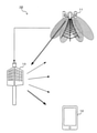
- FIG. 10 is a diagram showing a configuration example of a comparative example wireless communication system 10 provided with a dynamic reflector.
- a dynamic reflecting plate 13 provided with a plurality of reflecting elements reflects radio waves and relays them.
- the base station 11 acquires channel information (CSI: Channel State Information) for all of the plurality of reflecting elements included in the dynamic reflector 13 and adjusts the phase of the radio wave reflected by the dynamic reflector 13.
- CSI Channel State Information
- the base station 11 has an advanced signal processing function for acquiring and processing channel information for all of a plurality of reflecting elements, and reflects on the dynamic reflector 13. There is a need for a function to notify information about the phase for changing the characteristics.
- the base station 11 has an increased overhead for acquiring channel information, and if the number of reflecting elements is large, the amount of calculation for dynamically controlling the phase of the radio wave reflected by the dynamic reflector 13 is enormous. turn into.
- FIG. 1 is a diagram showing a configuration example of a wireless communication system 1 according to an embodiment.
- the wireless communication system 1 is configured such that, for example, a base station 2 and one or more wireless terminals 3 perform wireless communication via a reflection direction control system 4.
- the reflection direction control system 4 has, for example, a dynamic reflector 5-1, 5-2 and a reflection direction control device 6.
- the dynamic reflectors 5-1 and 5-2 receive radio signals transmitted by the wireless terminals 3, process the received signals, and transmit the received signals to the reflection direction control device 6.
- the reflection direction control device 6 estimates (positions) the position of the radio terminal 3 based on the signals input from the dynamic reflectors 5-1 and 5-2, respectively, and the dynamic reflectors 5-1 and 5- 2 The incident direction of the radio wave transmitted by the wireless terminal 3 is estimated for each of them.
- each of the plurality of reflecting elements reflects the radio waves incident in the estimated direction so that the dynamic reflectors 5-1 and 5-2 reflect them toward, for example, the base station 2.
- the reflection direction control device 6 uses, for example, preset position information of the base station 2 or radio waves transmitted by the base station 2 and reflected by the dynamic reflection plates 5-1 and 5-2. Based on the estimated position information of the base station 2, the phase of the radio wave to be reflected by each of the plurality of reflecting elements is calculated.
- the reflection direction control device 6 transmits information indicating the phase calculated for each of the plurality of reflection elements to the dynamic reflectors 5-1 and 5-2.
- a plurality of dynamic reflection plates 5-1 and 5-2 are used so as to efficiently relay the radio waves transmitted by the wireless terminal 3 to the base station 2 based on the phase information received from the reflection direction control device 6.
- the phase of the radio wave reflected by each of the reflecting elements is dynamically controlled.
- the reflection direction control system 4 dynamically controls the phase of the radio wave reflected by each of the plurality of reflecting elements so that the radio wave transmitted by the base station 2 is efficiently relayed to the wireless terminal 3.
- the reflection direction control system 4 will be described by taking the case where the dynamic reflectors 5-1 and 5-2 dynamically control the phase of the radio wave as an example, but the dynamic reflectors 5-1 and 5-2 will be described.
- it may be configured as a relay device that relays radio waves by a repeater having a power amplifier.
- the reflection direction of the radio wave can be determined. It can be controlled dynamically.
- FIG. 2 is a functional block illustrating the function of the dynamic reflector 5.
- the dynamic reflector 5 has, for example, a reflection unit 50, an antenna unit 52, a terminal signal processing unit 54, a control signal processing unit 56, and a reflection control unit 58.
- the reflecting unit 50 includes a plurality of reflecting elements 500, for example, a plurality of reflecting elements 500 are arranged in an array.
- the reflection element 500 reflects the radio wave transmitted by the base station 2 and the radio wave transmitted by the wireless terminal 3 according to the control of the reflection control unit 58.
- the reflective element 500 is a so-called metamaterial and has a property of shifting the phase when reflecting radio waves.
- the antenna unit 52 transmits and receives radio waves to and from the wireless terminal 3. Specifically, the antenna unit 52 receives a radio wave (wireless signal) transmitted by the wireless terminal 3 and outputs a received signal (notification signal or the like) to the terminal signal processing unit 54, and the terminal signal processing unit 54 outputs the received signal (notification signal or the like). The signal is transmitted to the wireless terminal 3.
- a radio wave wireless signal
- the terminal signal processing unit 54 outputs the received signal (notification signal or the like). The signal is transmitted to the wireless terminal 3.
- the terminal signal processing unit 54 has an RF unit 540, a signal processing unit 542, and a measurement unit 544.
- the RF unit 540 performs signal processing necessary for the signal processing unit 542 to perform digital signal processing on the radio waves received by the antenna unit 52. Further, the RF unit 540 performs the processing necessary for converting the transmission signal processed by the signal processing unit 542 into a predetermined radio wave and transmitting the signal. For example, the RF unit 540 performs processing such as signal amplification, down conversion from the system band, up conversion to the system band, and filtering.
- the signal processing unit 542 has a function of demodulating a wireless signal, for example, extracting an identification signal that identifies the wireless terminal 3 from the demodulated signal and outputting it to the measuring unit 544. Further, the signal processing unit 542 modulates the control signal used for wireless communication with the wireless terminal 3 and outputs the signal to the RF unit 540 in order to transmit the wireless signal.
- the measuring unit 544 has a function of measuring the received power or the arrival time of the radio signal. For example, the measuring unit 544 may directly measure the signal output by the RF unit 540, or may perform the measurement using the signal demodulated by the signal processing unit 542. Then, the measurement unit 544 associates the identification signal of the wireless terminal 3 input from the signal processing unit 542 with the measurement result and outputs the measurement result to the control signal processing unit 56.
- the control signal processing unit 56 has, for example, a signal processing unit 560.
- the signal processing unit 560 performs a process of transmitting, for example, a signal input from the measurement unit 544 to the reflection direction control device 6 via a communication unit (not shown). Further, the control signal processing unit 56 processes the signal received from the reflection direction control device 6 via a communication unit (not shown) and outputs the signal to the reflection control unit 58.
- the control signal processing unit 56 causes the reflection control unit 58 to control the reflection unit 50 based on a signal received from the reflection direction control device 6 (for example, control information for a phase such as a phase change amount).
- the reflection control unit 58 has a plurality of phase conversion units 580 and a phase control unit 582 that controls each of the phase conversion units 580.
- the phase conversion unit 580 is provided individually for each of the reflection elements 500, for example, and performs conversion that changes the phase of the radio wave reflected by the reflection element 500 according to the control from the phase control unit 582.
- the phase control unit 582 controls each of the phase conversion units 580 based on the signal input from the signal processing unit 560 (the phase calculated by the phase calculation unit 66 described later).
- the phase control unit 582 has a plurality of phase conversion units 580 so that the phase of the radio wave reflected by each of the plurality of reflection elements 500 is slightly shifted based on the control information for the phase transmitted by the reflection direction control device 6.
- the phase conversion unit 580 dynamically changes the phase shift amount by the reflective element 500 by changing the characteristics of the reflective element 500 according to the control of the phase control unit 582. Change to.
- the phase control unit 582 controls the reflecting unit 50 to perform beamforming in a predetermined direction by changing the characteristics of the metamaterial, multiplying the amount of the phase change, or imparting a predetermined delay.
- the phase control unit 582 selects the phase amount closest to the phase change amount transmitted by the reflection direction control device 6 from the configurable phase amounts. Controls each of the plurality of phase conversion units 580.
- FIG. 3 is a functional block illustrating the function of the reflection direction control device 6 according to the embodiment.
- the reflection direction control device 6 includes a signal processing unit 60, a position estimation unit 62, a direction estimation unit 64, a phase calculation unit 66, and a control unit 68.
- the signal processing unit 60 receives the signal transmitted by each dynamic reflector 5 via a communication unit (not shown), demodulates the signal, and outputs the signal obtained by demodulation to the position estimation unit 62. Further, the signal processing unit 60 transmits a signal input from the control unit 68 (for example, information indicating a phase described later) to each dynamic reflector 5 via a communication unit (not shown).
- the position estimation unit 62 estimates (positions) the position of each of the wireless terminals 3 using the information collected from the plurality of dynamic reflectors 5 demodulated by the signal processing unit 60. For example, the position estimation unit 62 estimates the position of each of the wireless terminals 3 based on the radio waves transmitted by each of the wireless terminals 3 to the plurality of dynamic reflectors 5.
- the signal demodulated by the signal processing unit 60 includes, for example, the identification number of each wireless terminal 3. Therefore, the position estimation unit 62 can use information such as the received power or the arrival time associated with the same identification number collected within a predetermined period.
- the position estimation unit 62 may estimate the position of the wireless terminal 3 by using the difference in the arrival time of the radio waves from the plurality of dynamic reflectors 5 with respect to the same wireless terminal 3. Any algorithm may be used as a method for estimating the position of each of the wireless terminals 3 using the received power or the arrival time.
- the signal transmitted by the wireless terminal 3 for the reflection direction control device 6 to estimate the position of the wireless terminal 3 is a signal of the same method as the wireless communication system used for communication between the base station 2 and the wireless terminal 3. It may be a signal of a different type.
- the wireless terminal 3 transmits a signal of a method specified by an existing wireless communication system such as a cellular system or a wireless LAN. Alternatively, a signal of another method specified by the user may be transmitted.
- the wireless terminal 3 may transmit a signal in the same frequency band, or may transmit a signal in a different frequency band.
- the wireless terminal 3 uses a high frequency band for communication with the base station 2, and the signal used by the reflection direction control device 6 to estimate the position of the wireless terminal 3 is transmitted using the low frequency band. May be good. As a result, it is possible to prevent the signal used by the reflection direction control device 6 for estimating the position of the wireless terminal 3 from being difficult to reach because it is a signal in the high frequency band, and positioning becomes easy.
- the position estimation unit 62 outputs the position information indicating the position of each of the estimated wireless terminals 3 to the direction estimation unit 64 and the control unit 68 in association with the identification number of the wireless terminal 3. Further, the position estimation unit 62 also outputs, for example, a predetermined identification number of the related dynamic reflector 5 to the direction estimation unit 64.
- the direction estimation unit 64 estimates the incident direction (and reflection direction) of the radio waves transmitted by each of the radio terminals 3 to the reflection unit 50 based on the positions of the radio terminals 3 estimated by the position estimation unit 62. For example, the direction estimation unit 64 dynamically reflects from the radio terminal 3 by using the position information of each of the radio terminals 3 input from the position estimation unit 62, the position information of each dynamic reflector 5, and the installation direction information. The direction of incidence of radio waves on the plate 5 (direction of reflection from the dynamic reflector 5 to the wireless terminal 3) is estimated.
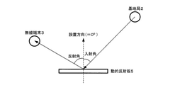
- FIG. 4 is a diagram schematically showing the relationship between the incident direction and the reflection direction of the radio wave with respect to the dynamic reflector 5 and the installation direction of the dynamic reflector 5.
- the incident direction and the reflection direction of the radio wave at the time of downlink transmission are shown, but at the time of uplink transmission, the incident direction and the reflection direction are reversed, and the incident angle and the reflection angle are exchanged.
- the direction estimation unit 64 has previously acquired information indicating the position and installation direction of each dynamic reflector 5.
- Information indicating the position and installation direction of the dynamic reflector 5 may be acquired by the reflection direction control device 6 when the dynamic reflector 5 is installed, or the dynamic reflector 5 may acquire its own position and its own position. It has a function of measuring the installation direction, and the reflection direction control device 6 may acquire its own position and the installation direction measured by the dynamic reflector 5.
- the dynamic reflector 5 may position its own position by GPS (Global Positioning System), or may measure its own installation direction and inclination by using a gyro sensor. Then, the dynamic reflector 5 transmits the measurement result to the reflection direction control device 6 every time the measurement is performed at an arbitrarily set timing. The reflection direction control device 6 sequentially updates and stores the measurement result received from the dynamic reflector 5.
- GPS Global Positioning System
- the direction estimation unit 64 may acquire direction information indicating the direction from the dynamic reflector 5 to the base station 2 in advance. For example, the direction estimation unit 64 may acquire direction information indicating the direction from the dynamic reflector 5 to the base station 2 when the dynamic reflector 5 is installed, or the position of the base station 2. And may be estimated based on the position of the dynamic reflector 5.
- the reflection direction control device 6 estimates the position of the base station 2 in the same manner as when the position of the wireless terminal 3 is estimated, and the position information of the dynamic reflector 5 acquired in advance and the motion acquired by the above-mentioned method.
- the direction from the dynamic reflector 5 to the base station 2 may be calculated by using the position information of the target reflector 5 and the installation direction.
- the direction estimation unit 64 may estimate the incident angle shown in FIG. 4 by using the direction information indicating the direction from the dynamic reflector 5 to the base station 2. Further, the direction estimation unit 64 is shown in FIG. 4 using the position information of the wireless terminal 3 estimated by the position estimation unit 62, the position information of the dynamic reflector 5 acquired by the above method, and the installation direction. The reflection angle may be estimated.
- the direction estimation unit 64 estimates the direction from the dynamic reflector 5 to the wireless terminal 3 with respect to the installation direction of the dynamic reflector 5 as a reflection angle for reflecting radio waves from the base station 2. .. Further, at the time of uplink transmission, the direction from the wireless terminal 3 to the dynamic reflector 5 with respect to the installation direction of the dynamic reflector 5 is estimated as the incident angle at which the radio wave from the wireless terminal 3 is incident.
- the direction estimation unit 64 when the direction estimation unit 64 has a plurality of identification numbers of the related dynamic reflectors 5 input from the position estimation unit 62, the direction estimation unit 64 indicates the incident direction (and the reflection direction) of the radio wave with respect to each of the dynamic reflector plates 5. ) Is estimated.
- the direction estimation unit 64 associates the direction information indicating the incident direction (and reflection direction) of the estimated radio wave with the identification number of each of the wireless terminals 3 and the identification number of each of the dynamic reflectors 5, and the phase calculation unit 64. Output to 66 (FIG. 3) and control unit 68.
- each of the plurality of reflecting elements 500 included in the plurality of dynamic reflectors 5 reflects the radio waves incident in the direction estimated by the direction estimation unit 64 so that the reflecting unit 50 reflects the radio waves in a predetermined direction.
- the phase of the radio wave to be to be calculated is calculated, and the information indicating the calculated phase is output to the control unit 68.
- the phase calculation unit 66 calculates the phase of the radio wave using, for example, the incident angle and the reflection angle shown in FIG.
- phase calculation unit 66 refers to the position information of the plurality of wireless terminals 3 instead of the direction from the dynamic reflection plate 5 to the wireless terminal 3, and the position where the most wireless terminals 3 are likely to exist.
- the phase of the radio wave may be calculated so that the reflecting unit 50 performs beamforming in the direction toward.
- the phase calculation unit 66 calculates the distance between the wireless terminals 3 using the position information of the plurality of wireless terminals 3, and clusters the plurality of wireless terminals 3 in which the distance between the wireless terminals 3 is equal to or less than a predetermined value. May be good.
- phase calculation unit 66 obtains the position center of gravity of the wireless terminal 3 in the cluster from the position information of each of the wireless terminals 3 in the cluster, and moves in place of the direction from the dynamic reflector 5 to the wireless terminal 3.
- the direction from the target reflector 5 to the position center of gravity of the wireless terminal 3 may be used.
- the phase calculation unit 66 reflects each of the plurality of reflecting elements 500 so that the reflecting unit 50 reflects the radio waves incident from the predetermined direction toward the cluster composed of the plurality of radio terminals 3 satisfying the predetermined conditions.
- the phase of the power wave may be calculated.
- phase calculation unit 66 may calculate the phase of the radio wave to be reflected by each of the plurality of reflection elements 500 for each reflection unit 50 based on a predetermined priority.
- the phase calculation unit 66 divides the plurality of reflecting elements 500 into a plurality of reflecting element groups, and the radio wave is different for each reflecting element group.
- the phase of the radio wave to be reflected by each of the reflecting elements 500 may be calculated so as to reflect the radio wave toward the terminal 3.
- the control unit 68 includes a CPU 680 and a memory 682, and controls each unit constituting the reflection direction control device 6. Further, the control unit 68 stores the information input from the position estimation unit 62, the direction estimation unit 64, and the phase calculation unit 66 in the memory 682, and for example, the signal processing unit stores the information indicating the phase calculated by the phase calculation unit 66. Output for 60.
- the memory 682 has, for example, the position information of each of the wireless terminals 3, the position information and the installation direction of each dynamic reflector 5, the direction from each dynamic reflector 5 to the wireless terminal 3, and the phase calculated by the phase calculation unit 66. Memorize the information to be shown.
- the memory 682 may be configured to output the position information and the installation direction of each dynamic reflector 5 to the direction estimation unit 64 in response to a call from the direction estimation unit 64. Further, the memory 682 may be configured to output the direction from the dynamic reflector 5 to the wireless terminal 3 to the phase calculation unit 66 in response to a call from the phase calculation unit 66.
- the control unit 68 when the reflection direction control device 6 receives a signal for estimating the position of the wireless terminal 3 from the plurality of wireless terminals 3, the control unit 68, for example, as in the following (1) to (4). The priority of each of the wireless terminal 3 and the dynamic reflector 5 is determined, and which dynamic reflector 5 should reflect the radio wave toward which wireless terminal 3 is determined. Then, the reflection direction control device 6 determines the information to be transmitted to each dynamic reflector 5 based on the determination.
- the control unit 68 controls the signal transmitted by the wireless terminal 3 so that the dynamic reflector 5 that measures the maximum received power reflects the radio wave toward the wireless terminal 3.
- the control unit 68 measures not only the dynamic reflector 5 that measures the maximum received power but also the dynamic that measures the next largest received power.
- a reflector 5 may be assigned.
- the control unit 68 calculates and calculates the distance from the wireless terminal 3 to the dynamic reflector 5 by using the position information of the wireless terminal 3 estimated by the position estimation unit 62 and the position information of the dynamic reflector 5.
- the wireless terminal 3 having the shortest distance may be assigned to the dynamic reflector 5.
- the control unit 68 uses not only the dynamic reflector 5 having the shortest distance but also the dynamic reflector 5 having the next shortest distance. May be assigned.
- the control unit 68 may group a plurality of wireless terminals 3 based on, for example, the positions of the wireless terminals 3. For example, the control unit 68 calculates the distance between the wireless terminals 3 based on the position information of the two wireless terminals 3, and if the calculated distance is equal to or less than a predetermined value, the control unit 68 associates the wireless terminals 3 as the same group.
- the reflection direction control device 6 may determine the direction of the group having a large number of wireless terminals 3 as the reflection direction of the dynamic reflector 5 after the grouping process.
- the control unit 68 is closest to the position of the representative wireless terminal arbitrarily selected in the group, the center of gravity point of the position of all the wireless terminals in the group, or the center of gravity point.
- the position of the wireless terminal and the distance between the dynamic reflector 5 may be calculated and assigned to each dynamic reflector 5 in units of groups in the same manner as in (2) described above.
- the control unit 68 may allocate not only one dynamic reflector 5 closest to the group but also two or more dynamic reflectors 5.
- the control unit 68 may allocate the dynamic reflector 5 to the wireless terminal 3 based on the combination of the received power and the position of the wireless terminal 3 estimated by the position estimation unit 62, for example.
- FIG. 5 is a sequence diagram showing an operation example of the wireless communication system 1.
- each dynamic reflector 5 measures, for example, the received power (S100), and the measurement result is transmitted to the reflection direction control device 6. Send.
- the reflection direction control device 6 estimates the position of the wireless terminal 3 based on the wireless signals transmitted by the wireless terminal 3 to the plurality of dynamic reflectors 5 (S102).
- the reflection direction control device 6 estimates the incident direction of the radio wave transmitted by the wireless terminal 3 to the reflection unit 50 based on the estimated positions of the wireless terminals 3 (S104).
- the reflection direction control device 6 calculates the phase of the radio wave to be reflected by each of the plurality of reflecting elements 500 so that the reflecting unit 50 reflects the radio wave incident in the estimated direction toward the base station 2. (S106), the calculation result is transmitted to each dynamic reflector 5 as control information.
- Each dynamic reflector 5 performs phase control (reflection direction control) of radio waves reflected by each of the plurality of reflecting elements 500 based on the received control information (S108). After that, the wireless terminal 3 and the base station 2 communicate with each other (downlink signal and uplink signal).
- FIG. 6 is a functional block illustrating the function of the modified example of the dynamic reflector 5 (dynamic reflector 5a).
- the dynamic reflector 5a has, for example, a reflection unit 50, an antenna unit 52, a terminal signal processing unit 54, a control signal processing unit 56a, and a reflection control unit 58.
- the same reference numerals are given to substantially the same configurations as those of the dynamic reflector 5 shown in FIG.
- the control signal processing unit 56a has a signal processing unit 562, a direction estimation unit 564, and a phase calculation unit 566.
- the signal processing unit 562 performs a process of transmitting, for example, a signal input from the measuring unit 544 to the reflection direction control device 6 via a communication unit (not shown). Further, the signal processing unit 562 processes the signal received from the reflection direction control device 6 via a communication unit (not shown) and outputs the signal to the direction estimation unit 564.
- the direction estimation unit 564 receives radio waves transmitted by each of the radio terminals 3 to the reflection unit 50 based on the information input from the signal processing unit 562 (the positions of the radio terminals 3 estimated by the position estimation unit 62). Estimate the direction (and reflection direction). For example, the direction estimation unit 564 uses the position information of each of the wireless terminals 3 and the position information and the installation direction information of each dynamic reflector 5, and the incident direction of the radio wave from the wireless terminal 3 to the dynamic reflector 5. (Reflective direction from the dynamic reflector 5 to the wireless terminal 3) is estimated.
- the direction estimation unit 564 uses a preset value or a value measured by the dynamic reflector 5 and sequentially updated as the position information and the installation direction information of each dynamic reflector 5. Then, the direction estimation unit 564 outputs the estimated incident direction of the radio wave (reflection direction from the dynamic reflector 5 to the radio terminal 3) to the phase calculation unit 566.
- each of the plurality of reflecting elements 500 of the plurality of dynamic reflectors 5 reflects the radio waves incident in the direction estimated by the direction estimation unit 564 so that the reflecting unit 50 reflects the radio waves in a predetermined direction.
- the phase of the radio wave to be to be calculated is calculated, and the information indicating the calculated phase is output to the phase control unit 582.
- FIG. 7 is a functional block illustrating the function of the modified example of the reflection direction control device 6 (reflection direction control device 6a).
- the reflection direction control device 6a includes a signal processing unit 60a, a position estimation unit 62, and a control unit 68a.
- the reflection direction control device 6a shown in FIG. 7 substantially the same configuration as the configuration of the reflection direction control device 6 shown in FIG. 3 is designated by the same reference numeral.
- the signal processing unit 60a receives the signal transmitted by each dynamic reflector 5 via a communication unit (not shown), demodulates the signal, and outputs the signal obtained by demodulation to the position estimation unit 62. Further, the signal processing unit 60a transmits a signal input from the control unit 68a (for example, position information of the wireless terminal 3) to each dynamic reflector 5 via a communication unit (not shown).
- the control unit 68a includes a CPU 680a and a memory 682a, and controls each unit constituting the reflection direction control device 6a. Further, the control unit 68a stores the information input from the position estimation unit 62 in the memory 682a, and outputs, for example, the position information of the wireless terminal 3 estimated by the position estimation unit 62 to the signal processing unit 60a.
- the memory 682 stores, for example, the position information of each wireless terminal 3, the position information of each dynamic reflector 5, the installation direction, and the like.
- control unit 68a may perform the allocation processing of the wireless terminal 3 and the dynamic reflector 5a and control the allocation result to be transmitted to the dynamic reflector 5a in the same manner as the control unit 68 described above. good. Further, the control unit 68a may control to transmit the position information to all of the dynamic reflectors 5a that have transmitted the information used for estimating the position of the wireless terminal 3. In the latter case, the control unit 68a determines the priority of each of the wireless terminal 3 and the dynamic reflector 5a in the direction estimation unit 564, for example, as in the following (1) to (4). It may be controlled as follows.
- control unit 68a lists the wireless terminals 3 in descending order of the received power measured by the dynamic reflector 5a, and prioritizes the direction of the wireless terminal 3 having the largest received power to determine the reflection direction.
- the control unit 68a updates the list every time the measurement result is received from the dynamic reflector 5a.
- the wireless terminal 3 can add the quality information measured by itself to the transmission signal (notification signal).
- the dynamic reflector 5a receives the notification signal, it confirms the quality information, creates a list arranged in order from the poor quality wireless terminal 3, and gives priority to the direction of the poor quality wireless terminal 3 in the reflection direction. decide.
- the control unit 68a updates the list every time the measurement result is received from the dynamic reflector 5a.
- the direction estimation unit 564 estimates the direction to be reflected with respect to each of the wireless terminals 3 based on, for example, the position information of each of the wireless terminals 3.
- the control unit 68a groups the wireless terminals 3 having the same or substantially the same direction or position. Further, the control unit 68a may take a difference in the estimation direction with respect to the two wireless terminals 3 and associate them as the same group if the difference is equal to or less than a predetermined value. In this case, the control unit 68a groups all the combinations of the wireless terminals 3.
- control unit 68a calculates the distance between the wireless terminals 3 based on the position information notified from the two wireless terminals 3, and the calculated distance is calculated. If it is less than a predetermined value, it may be associated as the same group.
- control unit 68a may determine the direction of the group having a large number of wireless terminals 3 as the reflection direction after the grouping process. At this time, the control unit 68a may use the estimated direction for the arbitrarily selected representative wireless terminal 3 in the group, or may use the average value of the estimated directions of all the wireless terminals 3 in the group. However, the direction of the wireless terminal 3 located in the direction closest to the average value may be used.
- control unit 68a is closest to the position of the arbitrarily selected representative wireless terminal 3 in the group, the center of gravity points of the positions of all the wireless terminals 3 in the group, and the center of gravity points.
- the direction to the position of the wireless terminal 3 may be applied.
- the control unit 68a calculates the distance between the wireless terminal 3 and the dynamic reflector 5a using the position information of the wireless terminal 3 that can be acquired from the notification signal and the position information of the dynamic reflector 5a itself, and the calculated distance.
- the wireless terminals 3 may be listed in ascending order, and the direction of the wireless terminal 3 having the shortest distance may be given priority as the reflection direction.
- the control unit 68a updates the list every time the measurement result is received from the dynamic reflector 5a.
- the control unit 68a lists the priorities based on two or more combinations of received power, quality information, estimation direction, or position based on the methods (1) to (4) described above, and sets the reflection direction. May be good.
- the reflection direction control device 6a when the reflection direction control device 6a receives the notification signals from the plurality of wireless terminals 3, the reflection direction control device 6a divides the plurality of reflection elements 500 included in the dynamic reflector 5a and controls the reflection direction for each of the divided reflection element groups. By doing so, the phase may be controlled so that one dynamic reflector 5a can reflect in a plurality of reflection directions.
- the N / 4 reflection elements 500 for each wireless terminal 3 May be used to control the wireless terminal 3 so as to reflect radio waves in each direction.
- the gain after reflection is reduced, the communication quality of the plurality of wireless terminals 3 can be improved at the same time.
- FIG. 8 is a sequence diagram showing an operation example of a modified example of the wireless communication system 1 provided with the dynamic reflector 5a and the reflection direction control device 6a.
- each dynamic reflector 5a measures, for example, the received power (S200), and the measurement result is transmitted to the reflection direction control device 6a. Send.
- the reflection direction control device 6a estimates (positions) the position of the wireless terminal 3 based on the wireless signals transmitted by the wireless terminal 3 to the plurality of dynamic reflectors 5a (S202), and dynamically obtains the positioning result. It is transmitted to the reflector 5a.
- each dynamic reflector 5a estimates the incident direction of the radio wave transmitted by the radio terminal 3 to the reflecting unit 50 based on the position of the radio terminal 3 received from the reflection direction control device 6a (S204). ..
- each dynamic reflecting plate 5a calculates the phase of the radio wave to be reflected by each of the plurality of reflecting elements 500 so that the reflecting unit 50 reflects the radio wave incident in the estimated direction toward the base station 2. (S206).
- each dynamic reflector 5 performs phase control (reflection direction control) of the radio wave reflected by each of the plurality of reflecting elements 500 (S208). After that, the wireless terminal 3 and the base station 2 communicate with each other (downlink signal and uplink signal).
- the position of each of the wireless terminals 3 is estimated based on the radio waves transmitted by the wireless terminals 3 to the plurality of reflecting units 50, and the reflecting element 500 is used. Since the phase of the radio wave reflected by each is controlled, the reflection direction of the radio wave can be dynamically controlled with a small amount of calculation.
- the base station 2 since the dynamic reflector 5 or the dynamic reflector 5a controls the phase of the radio wave reflected by each of the reflecting elements 500 when the radio wave arrives, the base station 2 It is also possible to expand the coverage by.
- the functions of the dynamic reflector 5, the dynamic reflector 5a, the reflection direction control device 6, and the reflection direction control device 6a are not limited to the above examples, and may be arbitrarily combined.
- the reflection direction control device 6 may have the function of the phase control unit 582 included in the dynamic reflector 5.
- each function of the reflection direction control device 6 and the reflection direction control device 6a may be partially or wholly configured by hardware such as PLD (Programmable Logic Device) or FPGA (Field Programmable Gate Array). , CPU or the like may be configured as a program executed by a processor.
- PLD Processable Logic Device
- FPGA Field Programmable Gate Array
- the reflection direction control device 6 and the reflection direction control device 6a according to the present invention can be realized by using a computer and a program, and the program can be recorded on a storage medium or provided through a network. ..
- FIG. 9 is a diagram showing a hardware configuration example of the reflection direction control device 6 according to the embodiment.
- the reflection direction control device 6 has an input unit 600, an output unit 610, a communication unit 620, a CPU 680, a memory 682, and an HDD 650 connected via a bus 660 and has a function as a computer.
- the reflection direction control device 6 is configured to be able to input / output data to / from a computer-readable storage medium 670.
- the input unit 600 is, for example, a keyboard, a mouse, or the like.
- the output unit 610 is a display device such as a display.
- the communication unit 620 is, for example, a wired and wireless network interface.
- the CPU 680 controls each part constituting the reflection direction control device 6 and performs predetermined processing and the like.
- the memory 682 and the HDD 650 are storage units for storing data and the like.
- the storage medium 670 can store a program or the like for executing the function of the reflection direction control device 6.
- the architecture constituting the reflection direction control device 6 is not limited to the example shown in FIG. Further, other configurations constituting the wireless communication system 1 such as the reflection direction control device 6a may have the same hardware configuration as the reflection direction control device 6.
- a "computer-readable storage medium” is a communication line for transmitting a program via a network such as the Internet or a communication line such as a telephone line, and dynamically holds the program for a short period of time. It may include a program or a program that holds a program for a certain period of time, such as a volatile memory inside a computer that is a server or a client in that case.
Landscapes
- Engineering & Computer Science (AREA)
- Computer Networks & Wireless Communication (AREA)
- Signal Processing (AREA)
- Mobile Radio Communication Systems (AREA)
- Radio Transmission System (AREA)
Abstract
Description
無線端末3は、動的反射板5からの距離が近いほど、動的反射板5による恩恵を受けやすい。そこで、制御部68は、無線端末3が送信した信号に対し、最大の受信電力を測定した動的反射板5が当該無線端末3に向けて電波を反射するように制御を行う。無線端末3の数に対して動的反射板5の数が多い場合、制御部68は、最大の受信電力を測定した動的反射板5だけでなく、次に大きい受信電力を測定した動的反射板5を割り当ててもよい。
制御部68は、位置推定部62が推定した無線端末3の位置情報と、動的反射板5の位置情報とを用いて、無線端末3から動的反射板5までの距離を算出し、算出した距離が最も短くなる無線端末3を動的反射板5に割り当ててもよい。無線端末3の数に対して動的反射板5の数が多い場合、制御部68は、距離が最も短くなる動的反射板5だけでなく、次に短い距離となる動的反射板5を割り当ててもよい。
制御部68は、例えば無線端末3それぞれの位置に基づいて、複数の無線端末3をグループ化してもよい。例えば、制御部68は、2つの無線端末3の位置情報に基づいて当該無線端末3間の距離を算出し、算出した距離が所定値以下であれば、当該無線端末3を同一グループとして関連付ける。
制御部68は、例えば受信電力と、位置推定部62が推定した無線端末3の位置との組合せに基づいて、無線端末3に対する動的反射板5を割り当ててもよい。
無線端末3は、動的反射板5aからの距離が近いほど、動的反射板5aによる恩恵を受けやすい。また、動的反射板5aからの距離が遠い無線端末3、すなわち受信電力が小さかった無線端末3を優先してしまうと、周辺に配置されている多くの動的反射板5aが同一の無線端末3に対して反応し、単一の無線端末3に対して必要以上に多くの動的反射板5aが使用され得る。
無線端末3は、自身が測定した品質情報を送信信号(通知信号)に付加することができるようにされている。動的反射板5aは、通知信号を受信すると、当該品質情報を確認し、品質が悪い無線端末3から順に並べたリストを作成し、品質が悪い無線端末3の方向を優先させて反射方向に決定する。なお、制御部68aは、動的反射板5aから測定結果を受信するたびに当該リストを更新する。
方向推定部564は、例えば無線端末3それぞれの位置情報に基づいて、無線端末3それぞれに対して反射すべき方向を推定する。
制御部68aは、通知信号から取得できる無線端末3の位置情報と、動的反射板5a自身の位置情報とを用いて無線端末3と動的反射板5aとの距離を算出し、算出した距離が短い順に無線端末3をリスト化し、距離が短い無線端末3の方向を優先して反射方向としてもよい。なお、制御部68aは、動的反射板5aから測定結果を受信するたびに当該リストを更新する。
制御部68aは、上述した(1)~(4)の方法に基づいて、受信電力、品質情報、推定方向又は位置の2以上の組み合わせに基づいて優先度をリスト化し、反射方向を設定してもよい。
Claims (7)
- 複数の反射素子をそれぞれ備える複数の反射部と、
1台以上の無線端末が複数の前記反射部に対して送信した電波に基づいて、無線端末それぞれの位置を推定する位置推定部と、
前記位置推定部が推定した無線端末それぞれの位置に基づいて、前記反射部に対して無線端末それぞれが送信する電波の入射方向を推定する方向推定部と、
前記方向推定部が推定した方向に入射される電波を前記反射部が所定方向に反射させるように、複数の前記反射素子それぞれが反射すべき電波の位相を算出する位相算出部と、
前記位相算出部が算出した位相に基づいて、複数の前記反射素子それぞれが反射する電波の位相を制御する位相制御部と
を有することを特徴とする反射方向制御システム。 - 前記位相算出部は、
所定方向から入射される電波を、所定条件を満たす複数の無線端末からなるクラスタに向けて前記反射部が反射させるように、複数の前記反射素子それぞれが反射すべき電波の位相を算出すること
を特徴とする請求項1に記載の反射方向制御システム。 - 前記位相算出部は、
予め定められた優先度に基づいて、複数の前記反射素子それぞれが反射すべき電波の位相を前記反射部ごとに算出すること
を特徴とする請求項1又は2に記載の反射方向制御システム。 - 前記位相算出部は、
複数の無線端末が送信した電波を1つの前記反射部が反射させる場合、複数の前記反射素子を複数の反射素子群に分割し、前記反射素子群ごとに異なる無線端末に向けて電波を反射させるように、前記反射素子それぞれが反射すべき電波の位相を算出すること
を特徴とする請求項1~3のいずれか1項に記載の反射方向制御システム。 - 複数の反射素子をそれぞれ備える複数の反射部に対して、1台以上の無線端末が送信した電波に基づいて、無線端末それぞれの位置を推定する位置推定部と、
前記位置推定部が推定した無線端末それぞれの位置に基づいて、前記反射部に対して無線端末それぞれが送信する電波の入射方向を推定する方向推定部と、
前記方向推定部が推定した方向に入射される電波を前記反射部が所定方向に反射させるように、複数の前記反射素子それぞれが反射すべき電波の位相を算出する位相算出部と、
前記位相算出部が算出した位相に基づいて、複数の前記反射素子それぞれが反射する電波の位相を制御する位相制御部と
を有することを特徴とする反射方向制御装置。 - 複数の反射素子をそれぞれ備える複数の反射部に対し、1台以上の無線端末が送信した電波に基づいて、無線端末それぞれの位置を推定する位置推定工程と、
推定した無線端末それぞれの位置に基づいて、前記反射部に対して無線端末それぞれが送信する電波の入射方向を推定する方向推定工程と、
推定した方向に入射される電波を前記反射部が所定方向に反射させるように、複数の前記反射素子それぞれが反射すべき電波の位相を算出する位相算出工程と、
算出した位相に基づいて、複数の前記反射素子それぞれが反射する電波の位相を制御する位相制御工程と
を含むことを特徴とする反射方向制御方法。 - 請求項5に記載の反射方向制御装置の各部としてコンピュータを機能させるための反射方向制御プログラム。
Priority Applications (3)
| Application Number | Priority Date | Filing Date | Title |
|---|---|---|---|
| JP2022538509A JP7487776B2 (ja) | 2020-07-20 | 2020-07-20 | 反射方向制御システム、反射方向制御装置、反射方向制御方法、及び反射方向制御プログラム |
| US18/016,370 US12464375B2 (en) | 2020-07-20 | 2020-07-20 | Reflection direction control system, reflection direction control device, reflection direction control method, and reflection direction control program |
| PCT/JP2020/028123 WO2022018800A1 (ja) | 2020-07-20 | 2020-07-20 | 反射方向制御システム、反射方向制御装置、反射方向制御方法、及び反射方向制御プログラム |
Applications Claiming Priority (1)
| Application Number | Priority Date | Filing Date | Title |
|---|---|---|---|
| PCT/JP2020/028123 WO2022018800A1 (ja) | 2020-07-20 | 2020-07-20 | 反射方向制御システム、反射方向制御装置、反射方向制御方法、及び反射方向制御プログラム |
Publications (1)
| Publication Number | Publication Date |
|---|---|
| WO2022018800A1 true WO2022018800A1 (ja) | 2022-01-27 |
Family
ID=79729112
Family Applications (1)
| Application Number | Title | Priority Date | Filing Date |
|---|---|---|---|
| PCT/JP2020/028123 Ceased WO2022018800A1 (ja) | 2020-07-20 | 2020-07-20 | 反射方向制御システム、反射方向制御装置、反射方向制御方法、及び反射方向制御プログラム |
Country Status (3)
| Country | Link |
|---|---|
| US (1) | US12464375B2 (ja) |
| JP (1) | JP7487776B2 (ja) |
| WO (1) | WO2022018800A1 (ja) |
Cited By (7)
| Publication number | Priority date | Publication date | Assignee | Title |
|---|---|---|---|---|
| JP2022117980A (ja) * | 2021-02-01 | 2022-08-12 | 株式会社Nttドコモ | 再構成可能なスマートサーフェスによって反射された無線信号を使用する、ユーザの位置特定及びトラッキングのための方法及び装置 |
| JP7280654B1 (ja) * | 2022-03-30 | 2023-05-24 | 国立大学法人東北大学 | 制御装置、コードブック生成装置、制御方法、コードブック生成方法及びプログラム |
| WO2024034286A1 (ja) * | 2022-08-12 | 2024-02-15 | ソニーグループ株式会社 | 通信制御装置および電波伝搬制御装置 |
| WO2024064580A1 (en) * | 2022-09-23 | 2024-03-28 | Qualcomm Incorporated | Low power passive mimo surface using aperture type radiators |
| WO2025083904A1 (ja) * | 2023-10-20 | 2025-04-24 | 株式会社Nttドコモ | 無線通信装置及び無線通信方法 |
| WO2025154148A1 (ja) * | 2024-01-15 | 2025-07-24 | 日本電信電話株式会社 | 無線中継システム及び無線中継方法 |
| WO2025177394A1 (ja) * | 2024-02-20 | 2025-08-28 | ソフトバンク株式会社 | 無線通信システム、および通信制御プログラム |
Families Citing this family (2)
| Publication number | Priority date | Publication date | Assignee | Title |
|---|---|---|---|---|
| US12538264B2 (en) * | 2021-03-03 | 2026-01-27 | Qualcomm Incorporated | Measurement of sounding reference signal reflections off of reconfigurable intelligent surfaces |
| WO2024027945A1 (en) * | 2022-08-01 | 2024-02-08 | NEC Laboratories Europe GmbH | Reconfigurable intelligent surface, ris, with sensing capabilities and method for operating the same |
Family Cites Families (7)
| Publication number | Priority date | Publication date | Assignee | Title |
|---|---|---|---|---|
| ES2153323B1 (es) * | 1999-06-07 | 2001-07-16 | Univ Madrid Politecnica | Reflectores planos en tecnologia impresa multicapa y su procedimiento de diseño. |
| JP5371633B2 (ja) * | 2008-09-30 | 2013-12-18 | 株式会社エヌ・ティ・ティ・ドコモ | リフレクトアレイ |
| JP2011064584A (ja) * | 2009-09-17 | 2011-03-31 | Denso Corp | アレーアンテナ装置及びレーダ装置 |
| FR2952261B1 (fr) * | 2009-11-05 | 2011-12-23 | Airbus Operations Sas | Systeme de communication dans un aeronef |
| JP4922426B2 (ja) | 2010-03-30 | 2012-04-25 | 株式会社エヌ・ティ・ティ・ドコモ | 反射板装置、無線基地局及び無線通信方法 |
| WO2019086113A1 (en) * | 2017-11-02 | 2019-05-09 | Telefonaktiebolaget Lm Ericsson (Publ) | Determining transmission parameters for downlink communication channels |
| EP4143596A1 (en) * | 2020-04-27 | 2023-03-08 | Nokia Technologies Oy | Ue positioning aided by reconfigurable reflecting surfaces such as intelligent reflecting surfaces (irs) |
-
2020
- 2020-07-20 US US18/016,370 patent/US12464375B2/en active Active
- 2020-07-20 JP JP2022538509A patent/JP7487776B2/ja active Active
- 2020-07-20 WO PCT/JP2020/028123 patent/WO2022018800A1/ja not_active Ceased
Non-Patent Citations (4)
| Title |
|---|
| HENK WYMEERSCH; JIGUANG HE; BENOIT DENIS; ANTONIO CLEMENTE; MARKKU JUNTTI: "Radio Localization and Mapping with Reconfigurable Intelligent Surfaces", ARXIV.ORG, CORNELL UNIVERSITY LIBRARY, 201 OLIN LIBRARY CORNELL UNIVERSITY ITHACA, NY 14853, 11 June 2020 (2020-06-11), 201 Olin Library Cornell University Ithaca, NY 14853 , pages 1 - 9, XP081681498 * |
| SHA HU , FREDRIK RUSEK: "Spherical Large Intelligent Surfaces", ARXIV.ORG, 5 July 2019 (2019-07-05), 201 Olin Library Cornell University Ithaca, NY 14853 , pages 1 - 5, XP081500668 * |
| YAOSHEN CUI; HAIFAN YIN: "An Efficient CSI Acquisition Method for Intelligent Reflecting Surface-assisted mmWave Networks", ARXIV.ORG, 27 December 2019 (2019-12-27), pages 1 - 6, XP081566621 * |
| ZHENG BEIXIONG; WU QINGQING; ZHANG RUI: "Intelligent Reflecting Surface-Assisted Multiple Access With User Pairing: NOMA or OMA?", IEEE COMMUNICATIONS LETTERS, vol. 24, no. 4, 27 January 2020 (2020-01-27), US , pages 753 - 757, XP011782143, ISSN: 1089-7798, DOI: 10.1109/LCOMM.2020.2969870 * |
Cited By (10)
| Publication number | Priority date | Publication date | Assignee | Title |
|---|---|---|---|---|
| JP2022117980A (ja) * | 2021-02-01 | 2022-08-12 | 株式会社Nttドコモ | 再構成可能なスマートサーフェスによって反射された無線信号を使用する、ユーザの位置特定及びトラッキングのための方法及び装置 |
| JP7307825B2 (ja) | 2021-02-01 | 2023-07-12 | 株式会社Nttドコモ | 再構成可能なスマートサーフェスによって反射された無線信号を使用する、ユーザの位置特定及びトラッキングのための方法及び装置 |
| JP7280654B1 (ja) * | 2022-03-30 | 2023-05-24 | 国立大学法人東北大学 | 制御装置、コードブック生成装置、制御方法、コードブック生成方法及びプログラム |
| WO2023188134A1 (ja) * | 2022-03-30 | 2023-10-05 | 国立大学法人東北大学 | 制御装置、コードブック生成装置、制御方法、コードブック生成方法及びプログラム |
| WO2024034286A1 (ja) * | 2022-08-12 | 2024-02-15 | ソニーグループ株式会社 | 通信制御装置および電波伝搬制御装置 |
| WO2024064580A1 (en) * | 2022-09-23 | 2024-03-28 | Qualcomm Incorporated | Low power passive mimo surface using aperture type radiators |
| US12212380B2 (en) | 2022-09-23 | 2025-01-28 | Qualcomm Incorporated | Low power passive MIMO surface using aperture type radiators |
| WO2025083904A1 (ja) * | 2023-10-20 | 2025-04-24 | 株式会社Nttドコモ | 無線通信装置及び無線通信方法 |
| WO2025154148A1 (ja) * | 2024-01-15 | 2025-07-24 | 日本電信電話株式会社 | 無線中継システム及び無線中継方法 |
| WO2025177394A1 (ja) * | 2024-02-20 | 2025-08-28 | ソフトバンク株式会社 | 無線通信システム、および通信制御プログラム |
Also Published As
| Publication number | Publication date |
|---|---|
| US12464375B2 (en) | 2025-11-04 |
| JP7487776B2 (ja) | 2024-05-21 |
| US20230276255A1 (en) | 2023-08-31 |
| JPWO2022018800A1 (ja) | 2022-01-27 |
Similar Documents
| Publication | Publication Date | Title |
|---|---|---|
| US12464375B2 (en) | Reflection direction control system, reflection direction control device, reflection direction control method, and reflection direction control program | |
| WO2022018815A1 (ja) | 反射方向制御システム、反射方向制御装置、反射方向制御方法、及び反射方向制御プログラム | |
| CN112205056B (zh) | 具有波束控制和无源互调感知的上行链路-下行链路协同调度 | |
| JP6582507B2 (ja) | 無線通信装置及びビーム制御方法 | |
| JP2022117980A (ja) | 再構成可能なスマートサーフェスによって反射された無線信号を使用する、ユーザの位置特定及びトラッキングのための方法及び装置 | |
| WO2022024223A1 (ja) | 反射方向制御方法、反射方向制御システム、反射方向制御装置、及び反射方向制御プログラム | |
| US20120190396A1 (en) | Radio base station and antenna weight setting method | |
| US11444677B2 (en) | Communication devices for efficient beam management | |
| US20240283517A1 (en) | Control method and communication control device | |
| CN111800875A (zh) | 资源分配方法、装置、存储介质及网络设备 | |
| US11159957B2 (en) | Base station apparatus, service provision method, and program | |
| US20230362719A1 (en) | System and method for lpwan | |
| EP3619817B1 (en) | Beamforming based on combined beams | |
| US12255702B2 (en) | Relay system, relay control device, relay method, and relay control program | |
| US11509378B2 (en) | Apparatus search for optimal directional beams | |
| WO2024147251A1 (ja) | 制御装置、中継装置、無線システム、基地局装置及びアンテナ方向決定方法 | |
| EP4383781A1 (en) | Control method, communication device, and program | |
| WO2023112094A1 (ja) | 無線通信システム、無線通信方法、無線通信処理装置および無線通信処理用プログラム | |
| EP1814345A1 (en) | Method for transferring signals in sectors by a base station of a wireless telecommunication network | |
| WO2021250755A1 (ja) | 情報処理方法、情報処理装置、無線通信システム、及び情報処理プログラム | |
| US8467743B2 (en) | Multi-antenna reception scheme | |
| JP7790597B2 (ja) | 無線通信システム、基地局、通信方法、及び非一時的なコンピュータ可読記憶媒体 | |
| US12375132B2 (en) | Relay control system, relay apparatus, and relay control method | |
| KR20240101451A (ko) | 통신 시스템에서 통신을 수행하는 장치 및 방법 | |
| JP2024149004A (ja) | 反射方向制御システム、制御装置、反射方向制御方法及び反射方向制御プログラム |
Legal Events
| Date | Code | Title | Description |
|---|---|---|---|
| 121 | Ep: the epo has been informed by wipo that ep was designated in this application |
Ref document number: 20946446 Country of ref document: EP Kind code of ref document: A1 |
|
| ENP | Entry into the national phase |
Ref document number: 2022538509 Country of ref document: JP Kind code of ref document: A |
|
| NENP | Non-entry into the national phase |
Ref country code: DE |
|
| 122 | Ep: pct application non-entry in european phase |
Ref document number: 20946446 Country of ref document: EP Kind code of ref document: A1 |
|
| WWG | Wipo information: grant in national office |
Ref document number: 18016370 Country of ref document: US |