WO2022018795A1 - 訓練データ作成方法、機械学習方法、消耗品管理装置及びコンピュータ可読媒体 - Google Patents
訓練データ作成方法、機械学習方法、消耗品管理装置及びコンピュータ可読媒体 Download PDFInfo
- Publication number
- WO2022018795A1 WO2022018795A1 PCT/JP2020/028095 JP2020028095W WO2022018795A1 WO 2022018795 A1 WO2022018795 A1 WO 2022018795A1 JP 2020028095 W JP2020028095 W JP 2020028095W WO 2022018795 A1 WO2022018795 A1 WO 2022018795A1
- Authority
- WO
- WIPO (PCT)
- Prior art keywords
- deterioration
- life
- degree
- consumable
- training data
- Prior art date
- Legal status (The legal status is an assumption and is not a legal conclusion. Google has not performed a legal analysis and makes no representation as to the accuracy of the status listed.)
- Ceased
Links
Images










Classifications
-
- G—PHYSICS
- G06—COMPUTING OR CALCULATING; COUNTING
- G06N—COMPUTING ARRANGEMENTS BASED ON SPECIFIC COMPUTATIONAL MODELS
- G06N20/00—Machine learning
-
- G—PHYSICS
- G06—COMPUTING OR CALCULATING; COUNTING
- G06F—ELECTRIC DIGITAL DATA PROCESSING
- G06F18/00—Pattern recognition
- G06F18/20—Analysing
- G06F18/21—Design or setup of recognition systems or techniques; Extraction of features in feature space; Blind source separation
- G06F18/214—Generating training patterns; Bootstrap methods, e.g. bagging or boosting
- G06F18/2148—Generating training patterns; Bootstrap methods, e.g. bagging or boosting characterised by the process organisation or structure, e.g. boosting cascade
-
- G—PHYSICS
- G01—MEASURING; TESTING
- G01N—INVESTIGATING OR ANALYSING MATERIALS BY DETERMINING THEIR CHEMICAL OR PHYSICAL PROPERTIES
- G01N21/00—Investigating or analysing materials by the use of optical means, i.e. using sub-millimetre waves, infrared, visible or ultraviolet light
- G01N21/17—Systems in which incident light is modified in accordance with the properties of the material investigated
- G01N21/1702—Systems in which incident light is modified in accordance with the properties of the material investigated with opto-acoustic detection, e.g. for gases or analysing solids
-
- G—PHYSICS
- G01—MEASURING; TESTING
- G01N—INVESTIGATING OR ANALYSING MATERIALS BY DETERMINING THEIR CHEMICAL OR PHYSICAL PROPERTIES
- G01N21/00—Investigating or analysing materials by the use of optical means, i.e. using sub-millimetre waves, infrared, visible or ultraviolet light
- G01N21/17—Systems in which incident light is modified in accordance with the properties of the material investigated
- G01N21/25—Colour; Spectral properties, i.e. comparison of effect of material on the light at two or more different wavelengths or wavelength bands
- G01N21/31—Investigating relative effect of material at wavelengths characteristic of specific elements or molecules, e.g. atomic absorption spectrometry
- G01N21/39—Investigating relative effect of material at wavelengths characteristic of specific elements or molecules, e.g. atomic absorption spectrometry using tunable lasers
-
- H—ELECTRICITY
- H01—ELECTRIC ELEMENTS
- H01S—DEVICES USING THE PROCESS OF LIGHT AMPLIFICATION BY STIMULATED EMISSION OF RADIATION [LASER] TO AMPLIFY OR GENERATE LIGHT; DEVICES USING STIMULATED EMISSION OF ELECTROMAGNETIC RADIATION IN WAVE RANGES OTHER THAN OPTICAL
- H01S3/00—Lasers, i.e. devices using stimulated emission of electromagnetic radiation in the infrared, visible or ultraviolet wave range
-
- G—PHYSICS
- G01—MEASURING; TESTING
- G01N—INVESTIGATING OR ANALYSING MATERIALS BY DETERMINING THEIR CHEMICAL OR PHYSICAL PROPERTIES
- G01N21/00—Investigating or analysing materials by the use of optical means, i.e. using sub-millimetre waves, infrared, visible or ultraviolet light
- G01N21/17—Systems in which incident light is modified in accordance with the properties of the material investigated
- G01N21/1702—Systems in which incident light is modified in accordance with the properties of the material investigated with opto-acoustic detection, e.g. for gases or analysing solids
- G01N2021/1704—Systems in which incident light is modified in accordance with the properties of the material investigated with opto-acoustic detection, e.g. for gases or analysing solids in gases
Definitions
- This disclosure relates to training data creation methods, machine learning methods, consumables management devices, and computer-readable media.
- the semiconductor exposure apparatus is simply referred to as an "exposure apparatus". Therefore, the wavelength of the light output from the exposure light source is being shortened.
- a gas laser device is used instead of the conventional mercury lamp.
- the gas laser apparatus for exposure a KrF excimer laser apparatus that outputs ultraviolet rays having a wavelength of 248 nm and an ArF excimer laser apparatus that outputs ultraviolet rays having a wavelength of 193 nm are used.
- the current exposure technology is immersion exposure, which shortens the apparent wavelength of the exposure light source by filling the gap between the projection lens and the wafer on the exposure device side with liquid and changing the refractive index of the gap. It has been put to practical use.
- immersion exposure is performed using an ArF excimer laser device as an exposure light source, the wafer is irradiated with ultraviolet light having an equivalent wavelength of 134 nm. This technique is called ArF immersion exposure.
- ArF immersion exposure is also called ArF immersion lithography.
- the spectral line width in the natural oscillation of the KrF and ArF excimer laser devices is as wide as about 350 to 400 pm, chromatic aberration of the laser beam (ultraviolet light) reduced and projected on the wafer by the projection lens on the exposure device side is generated and the resolution is increased. descend. Therefore, it is necessary to narrow the spectral line width of the laser beam output from the gas laser device until the chromatic aberration becomes negligible.
- the spectral line width is also called the spectral width.
- a narrow band section (Line Narrow Module) having a narrow band element is provided in the laser cavity of the gas laser device, and the narrow band section realizes a narrow band of the spectrum width.
- the band narrowing element may be an etalon, a grating, or the like.
- a laser device having a narrowed spectrum width in this way is called a narrowed band laser device.
- the training data creation method is a method of creating training data used for machine learning of a learning model for predicting the life of consumables of a laser device, and the use of consumables is started.
- Obtaining first life-related information including data for at least one life-related parameter of the consumable recorded for different numbers of oscillation pulses during the period from time to replacement, and the number of oscillation pulses.
- the machine learning method is a machine learning method for creating a learning model for predicting the life of consumables of a laser device, which is replaced after the consumables are used.
- Obtaining first life-related information including data for at least one life-related parameter of the consumable recorded for different numbers of oscillation pulses during the period up to, and consumables based on the number of oscillation pulses. Determining the first degree of deterioration, determining the second degree of deterioration of the consumables based on at least one life-related parameter, and determining the third degree of deterioration of the consumables based on the first degree of deterioration and the second degree of deterioration.
- the first life-related information It includes creating a learning model that predicts the degree of deterioration of consumables from the data of life-related parameters included in the information, and saving the created learning model.
- a computer-readable medium is a non-transient computer-readable medium in which a program is recorded, wherein the program, when executed by the computer, is the life of the consumables of the laser device. It is a program that realizes the function of creating training data used for machine learning of a learning model for predicting, and corresponds to different oscillation pulse numbers during the period from the start of use of consumables to the replacement.
- a function to acquire the first life-related information including data of at least one life-related parameter of the recorded consumable, a function to determine the first deterioration degree of the consumable based on the number of oscillation pulses, and a function to determine the first deterioration degree of the consumable, and at least one life.
- a function to determine a second degree of deterioration of consumables based on related parameters a function to determine a third degree of deterioration of consumables based on a first degree of deterioration and a second degree of deterioration, and a first life-related information. It includes a function of creating training data in which the third degree of deterioration is associated with the third degree of deterioration, and an instruction for realizing the computer.
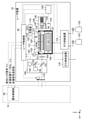
- FIG. 1 is a diagram schematically showing the configuration of an exemplary laser device.
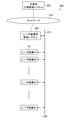
- FIG. 2 is a diagram schematically showing a configuration example of a laser management system in a semiconductor factory.
- FIG. 3 is a graph showing an example of the relationship between the gas pressure of a typical laser chamber and the number of oscillation pulses.
- FIG. 4 is a diagram showing a configuration of a laser management system of a semiconductor factory according to the first embodiment.
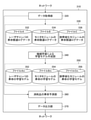
- FIG. 5 is a block diagram showing the functions of the consumables management server.
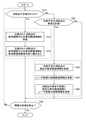
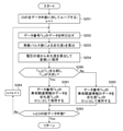
- FIG. 6 is a flowchart showing an example of processing contents in the data acquisition unit.
- FIG. 1 is a diagram schematically showing the configuration of an exemplary laser device.
- FIG. 2 is a diagram schematically showing a configuration example of a laser management system in a semiconductor factory.
- FIG. 3 is a graph showing an example of the relationship between the gas pressure of a typical laser chamber and the number of oscillation pulses.
- FIG. 4 is a diagram showing a configuration of a
- FIG. 7 is a flowchart showing an example of the processing content in the learning model creation unit.
- FIG. 8 is a graph showing an example of the relationship between the voltage of the laser chamber and the number of oscillation pulses, and shows an example of imparting a degree of deterioration to the life of the laser chamber based on the number of oscillation pulses and the voltage.
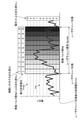
- FIG. 9 is a graph showing an example of the relationship between the voltage of the laser chamber and the number of oscillation pulses, and shows another example of imparting a degree of deterioration to the life of the laser chamber based on the number of oscillation pulses and the voltage.
- FIG. 8 is a graph showing an example of the relationship between the voltage of the laser chamber and the number of oscillation pulses, and shows an example of imparting a degree of deterioration to the life of the laser chamber based on the number of oscillation pulses and the voltage.
- FIG. 10 is a graph showing an example of the relationship between the gas pressure of the laser chamber and the number of oscillation pulses, and shows an example of imparting a degree of deterioration to the life of the laser chamber based on the number of oscillation pulses, gas pressure, and voltage.
- FIG. 11 is a flowchart showing an example 1 of the processing content applied to step S48 of FIG.
- FIG. 12 is a flowchart showing an example 1 of the processing content applied to step S104 of FIG.
- FIG. 13 is a flowchart showing Example 2 of the processing content applied to step S104 of FIG.
- FIG. 14 is a flowchart showing an example 3 of the processing content applied to step S104 of FIG.
- FIG. 11 is a flowchart showing an example 1 of the processing content applied to step S48 of FIG.
- FIG. 12 is a flowchart showing an example 1 of the processing content applied to step S104 of FIG.
- FIG. 13 is a flowchart showing Example 2 of the processing content applied to step S104 of
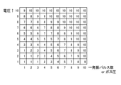
- FIG. 15 is a diagram showing an example of imparting a degree of deterioration based on a feature amount derived from two values of voltage and gas pressure.
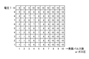
- FIG. 16 is a diagram showing another example of imparting a degree of deterioration based on a feature amount derived from two values of voltage and gas pressure.
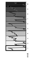
- FIG. 17 is a graph showing an image in which a plurality of data are included in one deterioration degree section divided into levels according to the number of oscillation pulses.
- FIG. 18 is a flowchart showing Example 2 of the processing content applied to step S48 of FIG.
- FIG. 19 is a flowchart showing an example of the processing content applied to step S104 of FIG.
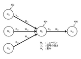
- FIG. 20 is a schematic diagram showing an example of a neural network model.
- FIG. 21 is an example of a neural network model for creating a learning model.
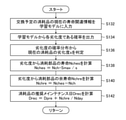
- FIG. 22 is a flowchart showing an example of processing contents in the life prediction unit of consumables.
- FIG. 23 is a flowchart showing an example of the processing content applied to step S70 of FIG. 22.
- FIG. 24 is a graph showing an example of calculating the life and remaining life of the laser chamber using the created learning model.
- FIG. 25 is a chart showing an example of the probability for each degree of deterioration divided into 10 levels.
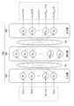
- FIG. 26 is a diagram showing an example of processing for predicting the life of consumables by a trained neural network model.
- FIG. 27 is a flowchart showing an example of processing contents in the data output unit.
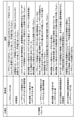
- FIG. 28 is a chart showing an example of life-related information of the laser chamber.
- FIG. 29 is a chart showing an example of life-related information of the laser chamber.
- FIG. 30 is a chart showing an example of life-related information of the laser chamber.
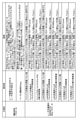
- FIG. 31 is a diagram showing an example of life-related information of the monitor module.
- FIG. 32 is a diagram showing an example of life-related information of the narrow band module.
- “Burst operation” means an operation in which a burst period in which a pulsed laser beam whose band is narrowed according to exposure is continuously oscillated and an oscillation pause period in which oscillation is paused according to the movement of a stage are alternately repeated. do.
- the laser device 10 is, for example, a KrF excimer laser device, which includes a laser control unit 90, a laser chamber 100, an inverter 102, an output coupling mirror 104, a narrow band module (Line Narrow Module: LNM) 106, and the like. It includes a monitor module 108, a charger 110, a pulse power module (PPM) 112, a gas supply device 114, a gas exhaust device 116, and an outlet shutter 118.
- PPM pulse power module
- the laser chamber 100 includes a first window 121, a second window 122, a cross flow fan (CFF) 123, a motor 124 for rotating the CFF 123, a pair of electrodes 125 and 126, an electrical insulator 127, and a pressure. It includes a sensor 128 and a heat exchanger (not shown).
- CFF cross flow fan
- the inverter 102 is a power supply device for the motor 124.
- the inverter 102 receives a command signal from the laser control unit 90 that specifies the frequency of the electric power supplied to the motor 124.
- the PPM 112 is connected to the electrode 125 via a feedthrough in the electrical insulator 127 of the laser chamber 100.
- the PPM 112 includes a semiconductor switch 129, a charging capacitor, a pulse transformer, and a pulse compression circuit (not shown).
- the output coupling mirror 104 is a partial reflection mirror, and is arranged so as to form an optical resonator together with the narrow band module 106.
- the laser chamber 100 is arranged on the optical path of this optical resonator.
- the narrowing band module 106 includes a beam expander using the first prism 131 and the second prism 132, a rotating stage 134, and a grating 136.
- the first prism 131 and the second prism 132 are arranged so as to magnify the beam of light emitted from the second window 122 of the laser chamber 100 and enter the grating 136.
- the grating 136 is retrowed so that the incident angle and the diffraction angle of the laser beam match.
- the second prism 132 is arranged on the rotating stage 134 so that the angle of incidence of the laser beam on the grating 136 and the angle of diffraction change when the rotating stage 134 rotates.
- the monitor module 108 includes a first beam splitter 141 and a second beam splitter 142, a pulse energy detector 144, and a spectrum detector 146.
- the first beam splitter 141 is arranged on the optical path of the laser beam output from the output coupling mirror 104, and a part of the laser beam is reflected and is arranged so as to be incident on the second beam splitter 142.
- the pulse energy detector 144 is arranged so that the laser light transmitted through the second beam splitter 142 is incident.
- the pulse energy detector 144 may be, for example, a photodiode that measures the light intensity of ultraviolet rays.
- the second beam splitter 142 is arranged so that a part of the laser beam is reflected and incident on the spectrum detector 146.
- the spectrum detector 146 is, for example, a monitor etalon measuring device that measures interference fringes generated by etalon with an image sensor. Based on the generated interference fringes, the center wavelength and spectral line width of the laser beam are measured.
- the gas supply device 114 is via a pipe with each of the inert gas supply source 152, which is a supply source of the inert laser gas, and the halogen gas supply source 153, which is a supply source of the laser gas containing halogen. Is connected.
- the inert laser gas is a mixed gas of Kr gas and Ne gas.
- the gas supply device 114 is connected to the laser chamber 100 via a pipe.
- the gas supply device 114 includes an automatic valve and a mass flow controller (not shown) for supplying a predetermined amount of an inert laser gas or a laser gas containing a halogen to the laser chamber 100, respectively.
- the gas exhaust device 116 is connected to the laser chamber 100 via piping.
- the gas exhaust device 116 includes a halogen filter (not shown) for removing halogen and an exhaust pump, and is configured to exhaust the halogen-removed laser gas to the outside.
- the exit shutter 118 is arranged on the optical path of the laser beam output from the laser device 10 to the outside.
- the laser device 10 is arranged so that the laser light output from the laser device 10 via the exit shutter 118 is incident on the exposure device 14.
- the laser control unit 90 desires an inert laser gas and a laser gas containing halogen in the laser chamber 100 via the gas supply device 114 after exhausting the gas in the laser chamber 100 via the gas exhaust device 116. Fill to the gas composition and total gas pressure.
- the laser control unit 90 rotates the motor 124 at a predetermined rotation speed via the inverter 102 to rotate the CFF 123. As a result, laser gas flows between the electrodes 125 and 126.
- the laser control unit 90 receives the target pulse energy Et from the exposure control unit 50 of the exposure device 14, and transmits the data of the charging voltage Vhv to the charger 110 so that the pulse energy becomes Et.
- the charger 110 charges the charging capacitor of the PPM 112 so that the charging voltage is Vhv.
- the laser control unit 90 inputs the trigger signal Tr2 to the semiconductor switch 129 of the PPM 112 in synchronization with the light emission trigger signal Tr1.
- the semiconductor switch 129 operates, the current pulse is compressed by the magnetic compression circuit of the PPM 112, and a high voltage is applied between the electrodes 125 and 126. As a result, a discharge is generated between the electrodes 125 and 126, and the laser gas is excited in the discharge space.
- the electrodes 125 and 126 are examples of "discharge electrodes" in the present disclosure.
- Excimer light is generated when the excited laser gas in the discharge space becomes the ground state. This excimer light oscillates by laser by being amplified back and forth between the output coupling mirror 104 and the band narrowing module 106. As a result, the pulsed laser beam with a narrow band is output from the output coupling mirror 104.
- the pulsed laser light output from the output coupling mirror 104 is incident on the monitor module 108.
- a part of the laser beam is sampled by the first beam splitter 141 and incident on the second beam splitter 142.
- the second beam splitter 142 transmits a part of the incident laser light and incidents it on the pulse energy detector 144, reflects the other part and incidents it on the spectrum detector 146.
- the pulse energy E of the pulse laser light output from the laser device 10 is measured by the pulse energy detector 144, and the measured pulse energy E data is transmitted from the pulse energy detector 144 to the laser control unit 90.
- center wavelength ⁇ and the spectral line width ⁇ are measured by the spectrum detector 146, and the data of the measured center wavelength ⁇ and the spectral line width ⁇ are transmitted from the spectrum detector 146 to the laser control unit 90.
- the laser control unit 90 receives data of the target pulse energy Et and the target wavelength ⁇ t from the exposure device 14.
- the laser control unit 90 controls the pulse energy based on the pulse energy E and the target pulse energy Et measured by the pulse energy detector 144.
- the laser control unit 90 controls the wavelength based on the center wavelength ⁇ and the target wavelength ⁇ t measured by the spectrum detector 146.
- the laser control unit 90 receives the target pulse energy Et and the target wavelength ⁇ t from the exposure device 14, and each time the light emission trigger signal Tr1 is input, the laser control unit 90 synchronizes with the light emission trigger signal Tr1 and the laser device 10 To output a pulsed laser beam.
- the laser control unit 90 executes, for example, the following gas control in order to suppress these adverse effects.
- Halogen injection control contains halogen gas that is mainly consumed by electric discharge in the laser chamber 100 during laser oscillation at a concentration higher than that of the halogen gas in the laser chamber 100. It is a gas control that replenishes the laser chamber 100 by injecting gas.
- Partial gas exchange control In the partial gas exchange control, a part of the laser gas in the laser chamber 100 is replaced with a new laser gas so as to suppress an increase in the concentration of the impurity gas in the laser chamber 100 during laser oscillation. Gas control.
- the gas pressure control is a gas control that controls the pulse energy by injecting a laser gas into the laser chamber 100 and changing the gas pressure P of the laser gas.
- the control of the pulse energy is usually performed by controlling the charging voltage Vhv, but it is impossible to compensate for the decrease in the pulse energy of the pulsed laser light output from the laser device 10 within the control range of the charging voltage Vhv. If so, gas pressure control is performed.
- the laser control unit 90 controls the gas exhaust device 116.
- the laser gas exhausted from the laser chamber 100 is exhausted to the outside of the laser apparatus 10 after the halogen gas is removed by a halogen filter (not shown).
- the laser control unit 90 transfers data of each parameter such as the number of oscillation pulses, the charging voltage Vhv, the gas pressure P in the laser chamber 100, the pulse energy E of the laser beam, and the spectral line width ⁇ via a local area network (not shown). It is transmitted to the management system 206 for the laser device (see FIG. 2).
- the major consumable replacement work performed by the field service engineer is the replacement work of the laser chamber 100, the narrowing band module 106, and the monitor module 108. ..
- the replacement time of these major consumables is generally controlled not by time but by the number of oscillation pulses of the laser device 10. Replacing these major consumables can take 3 to 10 hours. Among these major consumables, the consumable with the longest replacement time is the laser chamber 100.
- the laser device 10 is not limited to this example and may be applied to other laser devices.
- the laser device 10 may be an ArF excimer laser device or a XeCl excimer laser device.
- the gas control of the laser apparatus 10 shows a case where halogen injection control, partial gas exchange control, and gas pressure control are performed, but the gas control is not limited to this example, and the gas control is not limited to this example. It is not always necessary to carry out gas pressure control.
- the laser management system 200 includes a plurality of laser devices 10, a laser device management system 206, and a semiconductor factory management system 208.
- Each of the laser device management system 206 and the semiconductor factory management system 208 is configured by using a computer.
- Each of the management system 206 for the laser apparatus and the semiconductor factory management system 208 may be a computer system configured by using a plurality of computers.
- the semiconductor factory management system 208 is connected to the laser device management system 206 via the network 210.
- the network 210 is a communication line capable of transmitting information by wire, wireless, or a combination thereof.
- the network 210 may be a wide area network or a local area network.
- the laser device identification codes # 1, # 2, ... # K, ... # W are used here.
- w is the number of laser devices 10 included in the laser management system 200 in the semiconductor factory.
- w is an integer of 1 or more.
- k is an integer in the range of 1 or more and w or less.
- it may be referred to as a laser device #k.
- the laser devices # 1 to # w may have the same device configuration, or some or all of the laser devices # 1 to # w may have different device configurations.
- Each of the laser devices # 1 to # w and the laser device management system 206 is connected to the local area network 213.
- the local area network 213 is displayed as “LAN”.
- the laser device management system 206 manages the replacement timing of the main consumables of each laser device # 1 to # w mainly by the number of laser-oscillated pulses (oscillation pulse number) Np.
- the management system 206 for the laser device may display the maintenance management information on the display terminal, or may transmit the maintenance management information to the semiconductor factory management system 208 via the network 210.
- the management lines that manage the laser devices # 1 to # w by the laser device management system 206 are independent of each other, and are based on the maintenance management information output from each laser device # 1 to # w. , The manager of the semiconductor factory decides when to replace the main consumables of each laser device # 1 to # w.
- FIG. 3 is a graph showing an example of the relationship between the gas pressure P of a typical laser chamber 100 and the number of oscillation pulses Np.
- the electrodes 125 and 126 are consumed, the halogen gas in the laser gas is consumed, and the impurity gas is generated.
- a decrease in the concentration of halogen gas and an increase in impurity gas in the laser chamber 100 adversely affect the decrease in pulse energy of pulsed laser light and the stability of pulse energy.
- the replacement timing of the laser chamber 100 is indicated by an upward arrow.
- the operation after replacing the laser chamber 100 is as follows.
- Step 1 As for the gas pressure P immediately after replacing the laser chamber 100, the laser performance is maintained at the initial gas pressure Pch.
- Step 2 When the laser oscillation is continued, the gas pressure P rises due to the gas pressure control in order to maintain the laser performance due to the consumption of the discharge electrode and the generation of impurity gas.
- the graph shown by the thick line in FIG. 3 shows the transition of the gas pressure P in this step 2.
- Step 3 when the laser performance cannot be maintained even by gas pressure control, the laser oscillation is stopped and all gas is replaced.
- the timing of all gas exchange is indicated by a downward arrow.
- Step 4 Adjust oscillation after exchanging all gas. Gas pressure control is performed to restore laser performance.
- the gas pressure P when the laser performance is restored is referred to as "initial gas pressure after total gas exchange” and is referred to as Pini.
- Step 5 After that, steps 2 to 4 are repeated a plurality of times.
- the initial gas pressure Pini after all gas exchange gradually increases as the number of oscillation pulses Np increases.
- the graph shown by the thin line in FIG. 3 shows the transition of the initial gas pressure Pini.
- the value of the number of oscillation pulses as the standard life may be set for each major consumable of the laser device. However, due to individual differences in consumables, the number of oscillation pulses that reach the end of their life is not constant and varies. Even if the life of the consumable is longer than the standard life, the consumable may be replaced as regular maintenance at the time of the standard life. In addition, if the life of consumables is shorter than the standard life, planned replacement of consumables may not be possible and the production line may be stopped.
- the FSE empirically predicts the life of each consumable by looking at the log data of the gas pressure transition with respect to the number of oscillation pulses and other parameters related to the life as shown in FIG. It corresponds. Therefore, the prediction of the life of consumables and the response to replacement of consumables may depend on the ability of the FSE individual.
- FIG. 4 is a diagram showing the configuration of the laser management system 300 of the semiconductor factory according to the first embodiment. The difference between the configuration shown in FIG. 4 and FIG. 2 will be described.
- the laser management system 300 of the semiconductor factory shown in FIG. 4 has a configuration in which a consumables management server 310 is added to the configuration of the laser management system 200 of FIG.
- the consumables management server 310 is connected to the laser device management system 206 and the semiconductor factory management system 208 via the network 210.
- the consumables management server 310 has a configuration capable of transmitting and receiving data and signals to each of the laser device management system 206 and the semiconductor factory management system 208.
- FIG. 5 is a block diagram showing the functions of the consumables management server 310.
- the consumables management server 310 includes a data acquisition unit 320, a consumable life-related information storage unit 330, a learning model creation unit 340 by machine learning, a learning model storage unit 350, and a consumable life prediction unit 360. It includes a data output unit 370.
- the life-related information of consumables includes file A, file B, and file C.
- File A is a file in which the life-related log data of the laser chamber 100 is stored.
- File B is a file in which the life-related log data of the monitor module 108 is stored.
- File C is a file in which the life-related log data of the narrow band module 106 is stored.
- the consumable life-related information storage unit 330 includes a storage unit 332 for storing the file A, a storage unit 334 for storing the file B, and a storage unit 336 for storing the file C.
- the learning model creation unit 340 is a processing unit that creates a learning model by machine learning.
- the learning model storage unit 350 for consumables stores the learning model created by the learning model creation unit 340.
- the learning model storage unit 350 for consumables includes a storage unit 352 for storing the file Am, a storage unit 354 for storing the file Bm, and a storage unit 356 for storing the file Cm.
- File Am is a file in which the first learning model that performs the process of predicting the life of the laser chamber 100 is stored.
- the file Bm is a file in which the second learning model that performs the process of predicting the life of the monitor module 108 is stored.
- the file Cm is a file in which the third learning model that performs the process of predicting the life of the narrowing band module 106 is stored.
- the storage unit 332, 334, 336, 352, 354, 356 is configured by using a storage device such as a hard disk device and / or a semiconductor memory.
- the storage units 332, 334, 336, 352, 354, and 356 may be configured by using separate storage devices, or may be configured as a part of a storage area in one or more storage devices.
- each of the laser control unit 90, the exposure control unit 50, the laser device management system 206, the semiconductor factory management system 208, and the consumables management server 310 is the hardware and software of one or more computers. It can be realized by combination. Software is synonymous with program. Programmable controllers are part of the computer concept.
- the computer may be configured to include, for example, a CPU (Central Processing Unit) and a storage device. Programmable controllers are part of the computer concept.
- the computer may include a GPU (Graphics Processing Unit).
- the CPU and GPU included in the computer are examples of processors.
- the storage device is a non-temporary computer-readable medium that is a tangible object, and includes, for example, a memory that is a main storage device and a storage that is an auxiliary storage device.
- the computer-readable medium may be, for example, a semiconductor memory, a hard disk drive (HDD) device, a solid state drive (SSD) device, or a combination thereof.
- the program executed by the processor is stored in a computer-readable medium.
- the processor may be configured to include a computer-readable medium.
- control devices and processing devices such as the laser control unit 90, the exposure control unit 50, the laser device management system 206, the semiconductor factory management system 208, and the consumables management server 310 are FPGAs ( It may be realized by using an integrated circuit typified by FieldProgrammableGateArray) or ASIC (ApplicationSpecific IntegratedCircuit).
- control devices and processing devices may be connected to each other via a communication network such as a local area network or an Internet line.
- program units may be stored on both local and remote memory storage devices. Processors applied to the laser control unit 90, the exposure control unit 50, the laser device management system 206, the semiconductor factory management system 208, the consumables management server 310, and the like are special for performing various processes included in the present disclosure. It is configured or programmed in.
- the consumables management server 310 shown in FIG. 5 creates a learning model used for the process of predicting the life of the consumables of the laser device 10. It has a function to perform machine learning for this purpose and a function to perform processing for predicting the life of consumables using the created learning model.
- the consumables management server 310 is an example of the "consumables management device" in the present disclosure. First, a machine learning method for creating a learning model used for predicting the life of consumables in the consumables management server 310 and a method for creating training data used for the machine learning will be described.
- the data acquisition unit 320 continues from the laser device management system 206 in association with the oscillation pulse number Np for the entire period of use of the replaced consumables. Acquires life-related information including all data of life-related parameters recorded in the laser. The data acquisition unit 320 writes the data acquired from the laser device management system 206 into the consumable life-related information storage unit 330.
- the data acquisition unit 320 specifies a file to be written according to the type of the replaced consumable and writes the data.
- the data acquisition unit 320 writes the life-related log data, which is the life-related information of the laser chamber 100, in the file A.
- the data acquisition unit 320 writes the life-related log data, which is the life-related information of the monitor module 108, in the file B.
- the data acquisition unit 320 writes the life-related log data, which is the life-related information of the narrow band module 106, in the file C.
- the log data written in each of the file A, the file B, and the file C is an example of the "first life-related information" in the present disclosure.
- the data acquisition unit 320 is an example of the “information acquisition unit” in the present disclosure.
- the learning model creation unit 340 When the learning model creation unit 340 stores new life-related information data regarding the replaced consumables in the consumable life-related information storage unit 330, the learning model creation unit 340 acquires the newly saved life-related information data. Further, the learning model creation unit 340 calls a learning model corresponding to the replaced consumables from the consumables learning model storage unit 350.
- the learning model creation unit 340 calls the file Am.
- the learning model creation unit 340 calls the file Bm.
- the learning model creation unit 340 calls the file Cm.
- the learning model creation unit 340 performs machine learning based on the data of life-related parameters recorded during the period from the start of use to the replacement of the replaced consumables, and creates a new learning model. The details of the specific machine learning method will be described later.
- the new learning model created by the learning model creation unit 340 is stored in the learning model storage unit 350 of the consumables. When a new learning model is created by performing machine learning, the file of the learning model storage unit 350 is updated, and the latest learning model file is written to the learning model storage unit 350.
- the data acquisition unit 320 can receive a request signal for life prediction processing of consumables to be replaced from an external device.
- the external device here may be a semiconductor factory management system 208, a terminal device (not shown), or the like.
- the “consumables to be replaced” are consumables currently installed in the laser device 10 and are candidates for consideration to be replaced in the future.
- the data acquisition unit 320 When the data acquisition unit 320 receives a request for life prediction processing of the consumable to be replaced, the data of the current life-related information of the consumable to be replaced and the pulse scheduled to oscillate per day from the management system 206 for the laser device. The data of several Ndays is acquired.
- the data acquisition unit 320 transmits the data of the current life-related information of the consumable to be replaced and the data of the number of pulses scheduled to oscillate Nday per day to the consumable life prediction unit 360.
- the consumable life prediction unit 360 acquires the data of the current life-related information of the consumable to be replaced and the data of the number of pulses scheduled to oscillate Nday per day, and obtains a learning model corresponding to the consumable to be replaced. Called from the consumables learning model storage unit 350.
- the consumable item life prediction unit 360 reads the file Am from the consumable item learning model storage unit 350.
- the consumable life prediction unit 360 predicts the life of consumables by using a learning model based on the data of the current life-related information.
- the consumable life prediction unit 360 calculates the data of the predicted oscillation pulse number of the consumable life Nlife and the remaining life Nre to be replaced, and the recommended maintenance date Drec, and transmits these data to the data output unit 370. do.
- the recommended maintenance date Drec can be calculated using, for example, the following equation.
- Drec Dpre + Nre / Nday Dpre: Acquisition date of current life-related data of consumables
- the data output unit 370 outputs data of the predicted lifespan Nlife and remaining life Nre oscillation pulse number of the consumables to be replaced, and data representing the recommended maintenance date Drec. , Transmit to the laser device management system 206 via the network 210.
- the data output unit 370 is an example of the "information output unit" in the present disclosure.
- the management system 206 for the laser device notifies the semiconductor factory management system 208, the operator, the FSE, etc. of the predicted life of consumables to be replaced, the number of oscillation pulses of the remaining life Nre, and the recommended maintenance date Drec by display or mail. You may.
- This notification may be notified from the consumables management server 310 via the network 210.
- FIG. 6 is a flowchart showing an example of processing contents in the data acquisition unit 320.
- the processing and operation shown in the flowchart of FIG. 6 are realized, for example, by executing a program by a processor functioning as a data acquisition unit 320.
- step S12 the data acquisition unit 320 determines whether or not the consumables have been replaced. If the determination result in step S12 is Yes determination, the data acquisition unit 320 proceeds to step S14. Step S14 and step S16 are processing flows when creating a learning model.
- step S14 the data acquisition unit 320 receives information related to the entire life of the replaced consumables during the period of use. That is, when the consumables of the laser device 10 are replaced, the data acquisition unit 320 receives the information related to the entire life of the replaced consumables during the usage period from the laser device management system 206.
- step S16 the data acquisition unit 320 writes the total life-related information of the replaced consumables during the usage period in the life-related information storage unit 330. That is, the data acquisition unit 320 writes data in the file corresponding to the replaced consumables.
- the replaced consumable is the laser chamber 100, the monitor module 108, or the narrowing band module 106, and the data acquisition unit 320 stores data in file A, file B, or file C according to the type of consumable. Write.
- step S16 the data acquisition unit 320 proceeds to step S30.
- step S30 the data acquisition unit 320 determines whether or not to stop receiving information. If the determination result in step S30 is No, the data acquisition unit 320 returns to step S12.
- step S12 determines whether or not to calculate the life of the consumable to be replaced. For example, when a user inputs a request for life prediction for a consumable item to be replaced from an input device (not shown), the determination result in step S20 is a Yes determination.
- step S20 determines whether the determination result in step S20 is Yes determination. If the determination result in step S20 is Yes determination, the data acquisition unit 320 proceeds to step S22.
- Step S22, step S24 and step S26 are processing flows for calculating the expected life of consumables to be replaced. Calculating the expected life of a consumable means predicting the life of a consumable.
- step S22 the data acquisition unit 320 receives the current life-related information of the consumables to be replaced from the laser device management system 206.
- the data acquisition unit 320 receives the operation-related information of the laser device 10 from the management system 206 for the laser device.
- the operation-related information of the laser device 10 is the number of pulses scheduled to oscillate Nday per day. Specifically, it may be Nday, the number of pulses scheduled to oscillate per day, which is grasped from past operation data. Alternatively, the future operation schedule information may be acquired from the semiconductor factory management system 208, and the expected oscillation pulse number Nday per day may be calculated.
- step S26 the data acquisition unit 320 transmits the current life-related information and the operation-related information of the laser device 10 to the consumable life prediction unit 360.
- step S26 the data acquisition unit 320 proceeds to step S30. If the determination result in step S20 is No, the data acquisition unit 320 skips steps S22 to S26 and proceeds to step S30.
- step S30 If the determination result in step S30 is Yes determination, the data acquisition unit 320 ends the flowchart of FIG.
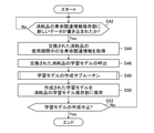
- FIG. 7 is a flowchart showing an example of the processing content in the learning model creation unit 340.
- the processing and operation shown in the flowchart of FIG. 7 are realized, for example, by executing a program by a processor that functions as a learning model creation unit 340.
- step S42 the learning model creation unit 340 determines whether or not new data has been written to the consumable life-related information storage unit 330. If the determination result in step S42 is No, the learning model creation unit 340 repeats step S42. If the determination result in step S42 is Yes determination, the learning model creation unit 340 proceeds to step S44.
- step S44 the learning model creation unit 340 acquires information related to the entire life of the replaced consumables during the period of use.
- the learning model creation unit 340 acquires the data written in the file (file A, file B, or file C) corresponding to the replaced consumables (laser chamber 100, monitor module 108, or narrowing band module 106). do.
- step S46 the learning model creation unit 340 calls the learning model of the replaced consumables. That is, the learning model creation unit 340 calls the learning model stored in the file (file Am, file Bm, or file Cm) corresponding to the replaced consumables.
- step S48 the learning model creation unit 340 executes the processing of the learning model creation subroutine.
- the learning model creation unit 340 performs machine learning based on the learning model corresponding to the replaced consumables and the life-related information, and creates a new learning model.
- step S50 the learning model creation unit 340 stores the newly created learning model in the consumable learning model storage unit 350.
- the learning model creation unit 340 saves the newly created learning model in a file (file Am, file Bm, or file Cm) corresponding to the replaced consumables. From the next time, the latest learning model is stored in the learning model storage unit 350 so that this new learning model can be used.
- step S52 the learning model creation unit 340 determines whether or not to stop the creation of the learning model. If the determination result in step S52 is No, the learning model creation unit 340 returns to step S42 and repeats steps S42 to S52. When the determination result in step S52 is Yes determination, the learning model creation unit 340 ends the flowchart of FIG. 7.
- the parameters of each initial learning model stored in the learning model storage unit 350 are set to arbitrary values before learning. It may have been done.
- the parameters of the learning model are changed to appropriate values, and a learning model that has acquired the processing function of predicting the life of consumables is created.
- the initial learning model may be a provisional learning model in which the parameters are adjusted to some extent by performing the same method as the machine learning method of the present embodiment in advance.
- the learning model created by the learning model creation unit 340 is learned to receive input of life-related information and output the deterioration degree of consumables as a prediction (inference) result.
- the process performed by the learning model creation unit 340 includes a process of creating training data used for machine learning and a process of performing machine learning using the created training data.
- the training data is synonymous with "learning data” or "learning data”.
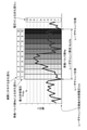
- FIG. 8 is a graph showing an example of the relationship between the voltage V of the laser chamber 100 and the number of oscillation pulses Np, and shows an example of imparting a degree of deterioration to the life of the laser chamber 100 by the number of oscillation pulses Np and the voltage V. ..
- the horizontal axis of FIG. 8 represents the number of oscillation pulses Np, and the vertical axis represents the voltage V applied between the electrodes 125 and 126. From the life-related log data of the laser chamber 100 stored in the file A, the data of the voltage V associated with the oscillation pulse number Np as shown in FIG. 8 can be read out.
- the deterioration degree DLn is an evaluation of the deterioration level of the laser chamber 100 by the oscillation pulse number Np, and the value indicating the deterioration degree DLn level becomes larger as the oscillation pulse number Np increases.
- the minimum level value may be 1 and the maximum level value may be 10.
- the maximum allowable voltage Vmax is set as the life, and the degree of deterioration DLv due to the voltage V is defined stepwise (for example, 10 steps).
- the maximum allowable voltage Vmax is, for example, a value in the range of 17.5 kV to 20.0 kV.
- the deterioration degree DLv is an evaluation of the deterioration level of the laser chamber 100 by the voltage V, and the value indicating the level of the deterioration degree DLv becomes larger as the voltage V increases.
- the minimum level value may be 1 and the maximum level value may be 10. It is preferable that the upper limit (maximum level value) of the deterioration degree DLv due to the voltage V and the upper limit of the deterioration degree DLn due to the number of oscillation pulses Np are the same, and the degree of deterioration relative to the upper limit of the deterioration degree according to each parameter is. It is preferable to arrange them roughly.
- the correspondence relationship between the voltage value and the level value may be determined in advance from the test result or the field data.
- the degree of deterioration DL given as a label indicating the degree of deterioration to the actual life of the state of the laser chamber 100 represented by the combination of parameters (Np, V) of the number of oscillation pulses Np and the voltage V is oscillation.
- the degree of deterioration DLn (Np) due to the number of pulses Np and the degree of deterioration DLv (V) due to the voltage V the degree of deterioration with a higher level of deterioration (the one with a larger level value) is defined as the degree of deterioration. According to the example of FIG.
- the level of the deterioration degree DLn due to the oscillation pulse number Np is “2”
- the level of the deterioration degree DLv due to the voltage V is “4”, so that the region is The degree of deterioration DL actually given is "4". Since the voltage V may have a large variation at the time of acquisition, a moving average value for a certain period (for example, one week) may be used.
- the range from the initial voltage Vch after replacement of the laser chamber 100 to the maximum allowable voltage Vmax is equally divided into 10 stages of levels 1 to 10.
- the level classification of the deterioration degree DLv by V is not limited to this example.
- the threshold voltage Vth is set for the voltage V
- the deterioration degree DLv at the threshold voltage Vth is set as level 6, etc.
- the level from the threshold voltage Vth to the maximum allowable voltage Vmax is equally divided. 6 to 10 may be set.
- the threshold voltage Vth may be, for example, 17.5 kV.
- the degree of deterioration DLv due to a low voltage V that is less than the threshold voltage Vth may be set to level 0.
- Level 0 means that the degree of deterioration is not evaluated (no evaluation).
- the threshold voltage Vth is an example of the "predetermined threshold" in the present disclosure.
- the deterioration due to the voltage V in this region is “3”. Therefore, the evaluation of the deterioration degree DLn based on the number of oscillation pulses Np is prioritized, and the deterioration degree DL actually applied to the region is “3”.
- the deterioration degree DLn due to the number of oscillation pulses Np is maintained as the deterioration degree DL actually applied.
- the degree of deterioration DLv due to the voltage V is evaluated as a level value in the latter half of the deterioration level (levels 6 to 10).
- the voltage V from the finding that the deterioration state becomes a problem when the voltage becomes higher than a certain voltage value, the deterioration due to the voltage V in the region higher than the value of the voltage V (threshold voltage Vth) to be noted.
- a configuration may be adopted in which a DLv label is given.
- the influence of the evaluation of the degree of deterioration DLv by the voltage V is relatively reduced in the region where the voltage V is lower than the threshold voltage Vth, and the number of oscillation pulses Np.
- the influence of the evaluation of the degree of deterioration DLn can be relatively increased.
- the evaluation of the deterioration degree DLv by the voltage V and the evaluation of the deterioration degree DLn by the number of oscillation pulses Np are emphasized to almost the same degree, and both are compared and actually given. It is possible to determine the degree of deterioration DL to be performed.
- the degree of deterioration DL actually applied is the degree of deterioration of which the level of the degree of deterioration is higher than the degree of deterioration of each of the two parameters.
- the degree of deterioration DLv due to a low voltage V less than the threshold voltage Vth is set to "level 0", but the same result can be obtained by setting "level 1" instead of "level 0". That is, the degree of deterioration DLv due to the voltage V when the voltage V is lower than the threshold voltage Vth may be a value equal to or less than the minimum level value (level 1) of the degree of deterioration DLn due to the number of oscillation pulses Np.
- the deterioration degree DL is given to the combination of the number of oscillation pulses Np and the voltage V (Np, V).
- the data associated with the parameter set of the combination of the number of oscillation pulses Np and the voltage V (Np, V) created in this way and the deterioration degree DL is used as training data for machine learning. That is, the combination data of the oscillation pulse number Np and the life-related parameters becomes the input data to the learning model, and the value of the level representing the deterioration degree DL corresponds to the label (teacher data) of the correct answer of the deterioration degree for the input data.
- the data of the parameter set of the combination of the number of oscillation pulses Np and the voltage V (Np, V) is the input data to the learning model, and the data of the deterioration degree DL corresponding to this is the correct label.
- the learning model creation unit 340 performs machine learning using the created supervised data, and creates a learning model that outputs a predicted value of the degree of deterioration with respect to the input of the combination of the number of oscillation pulses Np and the voltage V. That is, the learning model creation unit 340 predicts (infers) which level of the 10 levels of deterioration (levels 1 to 10) corresponds to the input data obtained by combining a plurality of parameters. Create a learning model to perform the task.
- the number of stages of the degree of deterioration is not limited to 10 and may be 2 or more appropriate stages.
- the degree of deterioration DLn due to the number of oscillation pulses Np is an example of the "first degree of deterioration” in the present disclosure.
- the degree of deterioration DLv due to the voltage V is an example of the "second degree of deterioration” in the present disclosure.
- the deterioration degree DL actually given is an example of the "third deterioration degree” in the present disclosure.
- the deterioration degree DL actually applied may be the deterioration degree DLn having the largest value among the deterioration degree DLn due to the number of oscillation pulses Np, the deterioration degree DLv due to the voltage V, and the deterioration degree DLp due to the gas pressure Pini. ..
- the gas pressure Pini may have a large variation at the time of acquisition, so a moving average value for a certain period (for example, one week) may be used.
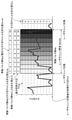
- FIG. 10 is a graph showing an example of the relationship between the gas pressure Pini of the laser chamber 100 and the oscillation pulse number Np, and the degree of deterioration until the life of the laser chamber 100 based on the oscillation pulse number Np, the gas pressure Pini, and the voltage V.
- the vertical axis of FIG. 10 represents the gas pressure Pini, and the unit is [Pa].
- the maximum allowable gas pressure Pmax is defined as the life, and the degree of deterioration DLp due to the gas pressure Pini is defined stepwise (for example, 10 steps).
- the range from the initial gas pressure Pch after replacement of the laser chamber 100 to the maximum allowable gas pressure Pmax is equally divided into 10 stages of levels 1 to 10.
- the setting of the level classification of the deterioration degree DLp by the gas pressure Pini is not limited to this example.
- a threshold gas pressure that serves as a threshold for the gas pressure Pini is set, the degree of deterioration at this threshold gas pressure is set to, for example, level 3, and the maximum allowable gas pressure Pmax up to level 10 is equally divided and set to levels 3 to 10. You can do it.
- the threshold gas pressure may be 2400 [Pa].
- the degree of deterioration corresponding to the gas pressure lower than the level 3 may be level 0 or level 1.
- the degree of deterioration DLnp due to the combination of parameters (Np, Pini) of the number of oscillation pulses Np and the gas pressure Pini is the degree of deterioration DLn (Np) due to the number of oscillation pulses Np and the degree of deterioration DLp (Pini) due to the gas pressure Pini.
- the degree of deterioration is the one with the higher level of deterioration.
- the degree of deterioration DLnvp to be given is the degree of deterioration with the highest level of deterioration among the degree of deterioration DLn (Np) due to the number of oscillation pulses Np, the degree of deterioration DLv (V) due to voltage V, and the degree of deterioration DLp (Pini) due to gas pressure Pini. And.
- the level of the degree of deterioration DLn due to the number of oscillation pulses Np is “5”
- the level of the degree of deterioration DLp due to the gas pressure Pini is “6”.
- the degree of deterioration DLnp based on the comprehensive judgment of the number of oscillation pulses Np and the gas pressure Pini is “6”.
- the level of the degree of deterioration DLv due to the voltage V is “7” (see FIG. 8).
- the degree of deterioration DLnvp based on the comprehensive judgment of the number of oscillation pulses Np, the voltage V, and the gas pressure Pini is "7".
- the degree of deterioration DLn, DLv, DLp according to each parameter with respect to the state of the consumables represented by the combination of the oscillation pulse number Np, the voltage V and the gas pressure Pini (Np, V, Pini). Based on the above, the degree of deterioration DLnbp is given.
- the data in which the combination of the number of oscillation pulses Np, the voltage V and the gas pressure P (Np, V, Pini) and the deterioration degree DLnbp created in this way are associated with each other is used as training data for machine learning.
- Machine learning is performed using such training data, and a level indicating the degree of deterioration of consumables is shown with respect to an input of a combination of oscillation pulse number Np, voltage V, and gas pressure P (Np, V, Pini) (that is,).
- Voltage V and gas pressure Pini are examples of "plural life-related parameters" in the present disclosure.
- Each of the degree of deterioration DLv due to the voltage V and the degree of deterioration DLp due to the gas pressure Pini is an example of the "second degree of deterioration” in the present disclosure.
- the total degree of deterioration DLnbp due to the number of oscillation pulses Np, the voltage V, and the gas pressure Pini is an example of the “third degree of deterioration” in the present disclosure.
- the life-related information for each consumable in the entire period of one cycle from the start of use to the replacement of the consumable is the same.
- the data is divided into multiple levels of deterioration, and training data is created in which the data of life-related parameters and the level indicating the degree of deterioration are associated with each other.
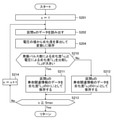
- FIG. 11 is a flowchart showing Example 1 of the processing content applied to step S48 of FIG. That is, FIG. 11 shows Example 1 of a learning model creation subroutine.
- step S102 of FIG. 11 the learning model creation unit 340 divides the information related to the entire life of the replaced consumables during the period of use into Smax stages according to the level of deterioration.
- Smax may be 10, for example, as illustrated in FIG.
- step S104 the learning model creation unit 340 creates data D (s) of life-related information in each stage divided into Smax stages.
- s is an integer representing the level of deterioration. s can take a value from 1 to Smax.
- the data D (s) of the life-related information of each stage of the deterioration degree DL divided into 10 stages for the laser chamber 100 is created.
- the data D (s) is data in which the life-related information and the level s of the deterioration degree DL are associated with each other, and is used as training data.
- the method of performing steps S102 and S104 to create training data is an example of the "training data creation method" in the present disclosure.
- step S106 the learning model creation unit 340 sets the value of the variable s representing the level of deterioration degree to the initial value "1".
- step S108 the learning model creation unit 340 inputs the data of D (s) into the learning model called in step S46 of FIG.
- step S110 of FIG. 11 the learning model creation unit 340 changes the parameters of the learning model so that the output of the learning model with respect to the input of the data D (s) becomes the level s.
- the learning model may be, for example, a neural network model.
- the learning model creation unit 340 changes the parameters of this learning model by machine learning using supervised data, and creates a new learning model.
- step S112 the learning model creation unit 340 determines whether or not the variable s is Smax or more. If the determination result in step S112 is No, the learning model creation unit 340 proceeds to step S114, increments the value of the variable s, and returns to step S108. When the determination result in step S112 is Yes determination, the learning model creation unit 340 ends the flowchart of FIG. 11 and returns to the flowchart of FIG. 7. That is, when the determination result in step S112 becomes Yes determination, the learning model is updated with a new learning model that reflects the result of the replaced consumables this time.
- steps S106 to S112 of FIG. 11 an example of learning for each level of deterioration degree has been described, but regarding the input of training data to the learning model, the learning unit is not for each level, but a random sample is used. It is preferable to study every arbitrary number of cases (for example, 1000 cases at a time). If training is performed for each level, the internal parameters of the learning model may be closer to the data of the level learned last, so it is better to randomly sample the training data group as the learning unit as much as possible.
- the learning model creation unit 340 is an example of a processing unit that implements the "training data creation method” and the “machine learning method” in the present disclosure.
- FIG. 12 is a flowchart showing Example 1 of the processing content applied to step S104 of FIG. As illustrated in FIGS. 8 and 9, the flowchart of FIG. 12 is a “life-related relationship at each stage” when the deterioration degree DLn due to the number of oscillation pulses Np is rewritten (overwritten) in consideration of the deterioration degree DLv due to the voltage V. This is an example of "process for creating information data D (s)".
- step S201 the learning model creation unit 340 sets the value of the variable s to the initial value "1".
- the variable s here represents a section defined by dividing the oscillation pulse number Np into Smax stages, and corresponds to the level of the deterioration degree DLn due to the oscillation pulse number Np.
- step S202 the learning model creation unit 340 reads out the data in the section s.
- the data of the voltage V in the section s is read out.
- step S204 the learning model creation unit 340 calculates the deterioration degree DLv from the value of the voltage V and stores it in the variable L. For example, when the value of the voltage V is 19 kV, the deterioration degree DLv is calculated as “6” (see FIG. 8).
- step S210 the learning model creation unit 340 compares the degree of deterioration “s” due to the number of oscillation pulses Np with the degree of deterioration “L” due to the voltage V, and determines whether or not “L” is larger than “s”. judge.
- step S210 If the determination result in step S210 is Yes determination (L> s), the learning model creation unit 340 proceeds to step S211.
- step S211th the learning model creation unit 340 saves the data of the life-related information in the section s as D (L) of the deterioration degree “L”.
- step S210 determines whether the determination result in step S210 is No determination (L ⁇ s).
- the learning model creation unit 340 proceeds to step S212.
- step S212 the learning model creation unit 340 stores the data of the life-related information in the section s as D (s) of the deterioration degree “s”.
- step S211 or S212 the learning model creation unit 340 proceeds to step S213.
- step S213 the learning model creation unit 340 determines whether or not the variable s is Smax or more. If the determination result in step S112 is No, the learning model creation unit 340 proceeds to step S214, increments the value of the variable s, and returns to step S202. When the determination result in step S213 is Yes determination, the learning model creation unit 340 ends the flowchart of FIG. 12 and returns to the flowchart of FIG.
- FIG. 13 is a flowchart showing Example 2 of the processing content applied to step S104 of FIG.
- the flowchart of FIG. 13 shows the data D (s) of the life-related information of each stage when the deterioration degree DLn due to the number of oscillation pulses Np is rewritten in consideration of the deterioration degree DLv due to the voltage V and the deterioration degree DLp due to the gas pressure Pini. ) Is an example of "Process to create".
- the same step numbers are assigned to the processing steps common to those in FIG. 12, and duplicate description will be omitted.
- step S204A the learning model creation unit 340 calculates the deterioration degree DLv from the value of the voltage V and stores it in the variable L1.
- step S204B the learning model creation unit 340 calculates the deterioration degree DLp from the gas pressure Pini and stores it in the variable L2.
- step S206 the learning model creation unit 340 sets the maximum values of L1 and L2 to L.
- step S209 the learning model creation unit 340 compares "s" and "L” and determines whether or not "L” is large.
- FIG. 14 is a flowchart showing an example 3 of the processing content applied to step S104 of FIG.
- the data D (s) of the life-related information of each stage when the deterioration degree DLn based on the number of oscillation pulses Np is rewritten.
- the same step numbers are assigned to the processing steps common to those in FIG. 13, and duplicate description will be omitted.
- step S205 after step S204B in FIG. 14, n labels are created by the value of an arbitrary single parameter or a combination of parameters, and the label Ln is given.
- the process of step S205 is repeated an arbitrary number of times depending on the number of types of a single parameter or a combination of parameters for evaluating the degree of deterioration.
- step S204A and step S204B may be carried out in step S205.
- Voltage V and gas pressure Pini are examples of a single parameter for evaluating the degree of deterioration.
- step S207 the learning model creation unit 340 sets the maximum value among L1 to Ln to L. Subsequent steps S209 and steps S211 to 214 are the same as in FIG.
- Life-related parameters such as voltage V and gas pressure Pini may be used independently (as a single parameter) to evaluate the degree of deterioration.
- a new (different) parameter may be defined by combining a plurality of parameters, and the degree of deterioration may be evaluated based on the value of this new parameter.
- One parameter can be derived by combining multiple r values (r dimensions).
- a method of converting from a plurality of parameters to one parameter for example, various methods such as a method of using a conversion formula for obtaining one value from r values by four arithmetic operations, a method of using a coefficient for the operation, and a dimension reduction method are used. Applicable.
- the two values of voltage V and gas pressure Pini are converted into values 1 to 100 representing new features.
- FIG. 15 is an example in which the correlation between the two values of voltage V and gas pressure Pini and the label is linear.
- the horizontal axis represents the degree of deterioration due to the number of oscillation pulses Np or the gas pressure Pini
- the vertical axis represents the degree of deterioration due to the voltage V.
- the numerical value displayed in each cell of the matrix of 10 rows ⁇ 10 columns shown in FIG. 15 represents a 10-step label given to a new feature quantity derived from the combination of the values of the two parameters.
- FIG. 16 is an example in which the voltage V has a small effect on the label and the gas pressure Pini has a large effect. As shown in FIG. 16, even if a new feature amount is defined so as to give a label of the degree of deterioration by the combination of these two parameters by emphasizing the evaluation of the degree of deterioration by the gas pressure Pini rather than the degree of deterioration by the voltage V. good.
- the "data set” here includes data of various parameters such as the number of oscillation pulses Np, the voltage V, and the gas pressure Pini of the laser device 10.
- the operating period is divided into 10 equal parts by the number of oscillation pulses Np, and a label of the degree of deterioration according to the number of oscillation pulses Np is assigned to each section.
- the method of counting the number of data when conditions 1 to 4 are satisfied is as follows. That is, the total number of data items in the data D is 500.
- Each of D (1), D (2) ... D (10) includes 50 data cases, and the total number of D (s), that is, the total data D is 500.
- FIG. 17 is a graph showing an image in which a plurality of data are included in one deterioration degree section.
- the horizontal axis of FIG. 17 represents the number of oscillation pulses, and the vertical axis is data of some parameters related to the lifetime.
- the horizontal axis is equally divided into 10 stages according to the number of oscillation pulses, and a section having a degree of deterioration of 1 to 10 is defined.
- FIG. 17 shows an example in which 10 data items are included in one section of the degree of deterioration for the sake of simplification, but the number of data items included in one section is not limited to this example.
- an arbitrary number of cases may be randomly sampled from all data D for learning. For example, when the total number of data items is 500, instead of learning in order for each deterioration degree, a predetermined number of data of various deterioration degrees are randomly selected from all the data D (for example, 50 cases). Are extracted without duplication and learned 10 times.
- the voltage V or the voltage V is applied to each data in the section, that is, for all data D. It is preferable to rewrite the degree of deterioration based on the gas pressure Pini.
- FIG. 18 is a flowchart showing Example 2 of the processing content applied to step S48 of FIG.
- FIG. 18 shows Example 2 of a learning model creation subroutine. Instead of the flowchart described in FIG. 11, the flowchart shown in FIG. 18 can be applied.
- Step S102 and step S104 shown in FIG. 18 are the same as those in FIG.
- the data D (s) in step S104 of FIG. 18 includes all data in which s is 1 to Smax.
- step S116 the learning model creation unit 340 sets the variable n to "1" as the initial value, and sets the variable m to "1000".
- the variable n here indicates the number of loops of the processing described later.
- the variable m represents the number of data items to be extracted as a learning unit from all the data D.
- step S117 the learning model creation unit 340 randomly extracts m items from the data D. At this time, the ones that have been extracted once shall not be extracted in duplicate. Data of various degrees of deterioration may be mixed in m cases.
- the data D here is a set of all data including D (1), D (2) ... D (Smax).
- step S118 the learning model creation unit 340 calls the data of each D (s) and inputs them into the learning model.
- step S120 the learning model creation unit 340 changes the parameters of the learning model so that the probability that the output of the learning model becomes the level s increases.
- the learning model is a neural network model described later, and the parameters of this model are changed by supervised data to create a new learning model.
- step S122 the learning model creation unit 340 determines whether or not the product of n and m is N or more. N is the total number of data items in the data D. If the determination result in step S122 is No, the learning model creation unit 340 proceeds to step S124, increments the value of n, and returns to step S117. When the determination result in step S122 is Yes determination, the learning model creation unit 340 ends the flowchart of FIG. 18 and returns to the flowchart of FIG. 7. That is, when the determination result in step S112 becomes Yes determination, the learning model is updated with a new learning model that reflects the result of the replaced consumables this time.
- steps S116 to S122 may be repeated a plurality of times by setting the number of epochs to a value of 2 or more.
- FIG. 19 is a flowchart showing an example of the processing content applied to step S104 of FIG. As illustrated in FIGS. 8 and 9, the flowchart of FIG. 19 is a “data D of life-related information at each stage” when the deterioration degree DLn due to the number of oscillation pulses Np is rewritten in consideration of the deterioration degree DLv due to the voltage V. This is an example of "process for creating (s)".
- step S251 of FIG. 19 the learning model creation unit 340 sets the index k representing the data number to the initial value “1”.
- the processing after step S252 loops for all the data in the data set of data D.
- step S252 the learning model creation unit 340 reads out the data of the data number "k".
- step S253 the learning model creation unit 340 calculates the degree of deterioration s based on the number of oscillation pulses Np.
- step S254 the learning model creation unit 340 calculates the deterioration degree DLv from the value of the voltage V and stores it in the variable L.
- step S260 the learning model creation unit 340 compares "s" and “L”, and determines whether or not "L” is larger than "s”. If the determination result in step S260 is Yes determination, the learning model creation unit 340 proceeds to step S261. In step S261, the learning model creation unit 340 saves the data of the life-related information of the data number “k” as the data D (L) of the deterioration degree “L”.
- step S260 determines whether the determination result in step S260 is No. If the determination result in step S260 is No, the learning model creation unit 340 proceeds to step S262. In step S262, the learning model creation unit 340 saves the data of the life-related information of the data number “k” as the data D (s) of the deterioration degree “s”.
- step S261 or S262 the learning model creation unit 340 proceeds to step S263.
- step S263 the learning model creation unit 340 determines whether or not the value of k is equal to or greater than the total number of data items N of the data D. If the determination result in step S263 is No, the learning model creation unit 340 proceeds to step S264, increments the value of the index k, and returns to step S252. When the determination result in step S263 is Yes determination, the learning model creation unit 340 ends the flowchart of FIG. 19 and returns to the flowchart of FIG.
- FIG. 19 a flowchart corresponding to the flowchart as described with reference to FIG. 13 or 14 may be applied.
- FIG. 20 is a schematic diagram showing an example of a neural network model.
- circles represent neurons, and straight lines with arrows represent signal flows.
- the layer number of the neural network having a layer structure is i
- the neuron number is j
- the strength of the signal output from the neuron N ij is X ij
- the signal is X ij .
- Wij be the weight of the connection between neurons between the i-layer and the (i + 1) layer.
- the neurons N 11 , N 12 , and N 13 of the input layer 402 output signals having signal strengths of X 11 , X 12 , and X 13, respectively.
- the neuron N 21 of the hidden layer 404 is determined when the weighted signal sum (W 11 ⁇ X 11 + W 12 ⁇ X 12 + W 13 ⁇ X 13 ) of the input signals X 11 , X 12 , and X 13 is larger than the threshold value.
- Signal X 21 is output.
- the neuron N 21 outputs the signal X 21 when W 11 ⁇ X 11 + W 12 ⁇ X 12 + W 13 ⁇ X 13 ⁇ b 21> 0.
- “-B 21 " is called the bias of neuron N 21.
- Neural network model parameters include weights and biases of connections between neurons.
- FIG. 21 is an example of a neural network model when creating a learning model.
- the neural network model 400 includes an input layer 402, a hidden layer 404, and an output layer 406.
- Input layer 402 includes n neurons N 11 ⁇ N 1n, each neuron N 11 ⁇ N 1n, log data when the deterioration degree s in the life-related information of the replaced consumable is input.
- the hidden layer 404 includes m neurons N 21 to N 2 m , and signals output from neurons N 11 to N 1n of the input layer 402 are input to each neuron in the hidden layer 404.
- a parameter W1 having a different weight can be set for each of these input signals.
- the weight parameter W1 is collectively referred to as "weight parameter W1" by collectively referring to the respective weights for the signals input to the neurons N 21 to N 2 m of the hidden layer 404.
- the output layer 406 includes p neurons N 31 to N 3P , and signals output from neurons N 21 to N 2 m of the hidden layer 404 are input to each neuron of the output layer 406.
- the number p of neurons in the output layer 406 may be the same as the number of stages (Smax) of the degree of deterioration.
- Parameter W2 with different weights can be set for each of these input signals.
- the weight parameter W2 is collectively referred to as "weight parameter W2" by collectively referring to the respective weights for the signals input to the neurons N 31 to N 3p of the output layer 406.
- the probability of the degree of deterioration here means a score indicating the certainty corresponding to each level of the degree of deterioration.
- the life-related information (log data) D1 (s), D2 (s) ... Dn (s) of the replaced consumables is input to the input layer 402. Enter each.
- the output from the output layer 406 results in a probability of Lv (s) approaching 1 and a probability of other degradation degrees approaching 0, respectively, among neurons. Adjust the weight and bias of.
- the machine learning method is understood as a method of producing a prediction model (learned model) trained to output a predicted value of the deterioration degree of the consumable in response to the input of the life-related information of the consumable. Will be done.
- FIG. 22 is a flowchart showing an example of processing contents in the consumable life prediction unit 360.
- the processing and operation shown in the flowchart of FIG. 22 are realized, for example, by executing a program by a processor that functions as a consumable life prediction unit 360.
- step S62 of FIG. 22 the consumable life prediction unit 360 determines whether or not the current life-related information of the consumable to be replaced has been received. If the determination result in step S62 is No, the consumable life prediction unit 360 repeats step S62. If the determination result in step S62 is Yes determination, the consumable life prediction unit 360 proceeds to step S64.
- step S64 the consumable life prediction unit 360 acquires the current life-related information of the consumable to be replaced.
- the current life-related information acquired in step S64 is an example of the "second life-related information" in the present disclosure.
- step S66 the consumable life prediction unit 360 acquires the operation-related information of the laser device 10.
- step S68 the consumable life prediction unit 360 calls a learning model of the consumable to be replaced.
- the learning model stored in the file (file Am, file Bm, or file Cm) corresponding to the consumables to be replaced (laser chamber 100, monitor module 108, or narrowing band module 106) is called.
- step S70 the consumable life prediction unit 360 calculates the life using the learning model. That is, the consumable life prediction unit 360 calculates the life, the remaining life, and the recommended maintenance date using the learning model based on the current life-related information of the consumable to be replaced.
- step S72 the consumable life prediction unit 360 transmits each data of the consumable life to be replaced, the remaining life, and the recommended maintenance date to the data output unit 370.
- step S74 the consumable life prediction unit 360 determines whether or not to stop the calculation of the predicted life of the consumable. If the determination result in step S74 is No, the consumable life prediction unit 360 returns to step S62 and repeats steps S62 to S74. When the determination result in step S74 is Yes determination, the consumable life prediction unit 360 ends the flowchart of FIG. 22.
- FIG. 23 is a flowchart showing an example of a subroutine of processing for performing life calculation using a learning model. That is, FIG. 23 is a flowchart showing an example of the processing content of step S70 of FIG.
- step S132 of FIG. 23 the consumable life prediction unit 360 inputs the current life-related information of the consumable to be replaced into the learning model.
- step S134 the consumable life prediction unit 360 outputs the probabilities of each deterioration degree Lv (1) to Lv (Smax) from the learning model.
- the consumable life prediction unit 360 determines the current degree of deterioration s of the consumable from the probability distribution of the degree of deterioration.
- the degree of deterioration having the highest probability may be extracted.
- an approximate curve may be obtained from the probability distribution of the degree of deterioration, and the degree of deterioration s of the highest probability distribution may be obtained.
- the degree of deterioration s is not an integer, but a numerical value of a decimal point or less is obtained.
- the life and the remaining life of the consumable can be predicted with higher accuracy than in the case of the first example.
- step S138 the consumable life prediction unit 360 further calculates the consumable life Nches from the degree of deterioration obtained in step S136.
- " ⁇ " in the formula represents multiplication.
- step S140 the consumable life prediction unit 360 further calculates the remaining life Nchre of the consumable from the degree of deterioration obtained in step S136.
- step S142 the consumable life prediction unit 360 calculates the recommended maintenance date Drec of the consumable.
- step S142 the consumable life prediction unit 360 ends the flowchart of FIG. 23 and returns to the flowchart of FIG. 22.
- FIG. 24 shows an example of calculating the life and remaining life of the laser chamber 100 using the created learning model.
- the consumable life prediction unit 360 acquires the life-related information of the current laser chamber 100.
- the data of the number of oscillation pulses Nch of the current laser chamber 100 is acquired.
- FIG. 25 shows an example of the probability for each degree of deterioration in 10 stages. In the example of FIG. 25, it is determined that the probability of deterioration degree 7 is the highest.
- the predicted life Nches of the laser chamber 100 currently in operation is calculated by the following equation 1.
- Nches Nch ⁇ 10/7 (Equation 1)
- the remaining life Nchre is calculated by the following formula 2.
- FIG. 26 is an example of processing for predicting the life of consumables by the trained neural network model 400.
- the network structure of the neural network model 400 has the same configuration as that of FIG. 21.
- the weight parameters W1 and W2 between neurons are set to values optimized by the learning mode described with reference to FIG. 21.
- FIGS. 21 and 26 show an example in which the hidden layer 404 of the neural network model 400 is one layer, but the present invention is not limited to this, and there are a plurality of hidden layers 404. May be good.
- machine learning by supervised learning is shown, but the present invention is not limited to this example, and machine learning by unsupervised learning may be performed.
- the input data can be reduced in dimension and the features in those datasets can be clustered into similar ones. This result can be used to predict the output by setting some criteria and allocating the output to optimize it.
- FIG. 27 is a flowchart showing an example of processing contents in the data output unit 370.
- the processing and operation shown in the flowchart of FIG. 27 are realized, for example, by executing a program by a processor functioning as a data output unit 370.
- step S82 the data output unit 370 determines whether or not the life data of the consumable to be replaced has been received. If the determination result in step S82 is No, the data output unit 370 repeats step S82. If the determination result in step S82 is Yes determination, the data output unit 370 proceeds to step S84.
- step S84 the data output unit 370 reads the data of the consumables to be replaced, the remaining life, and the recommended maintenance date.
- step S86 the data output unit 370 transmits data on the life of the consumable to be replaced, the remaining life, and the recommended maintenance date.
- the data transmission destination may be the laser device management system 206 and / or the semiconductor factory management system 208. Further, the data transmission destination may be a terminal device (not shown) connected to the network 210.
- step S88 the data output unit 370 determines whether or not to stop the transmission of data. If the determination result in step S88 is No, the data output unit 370 returns to step S82 and repeats steps S82 to S88. When the determination result in step S88 is Yes determination, the data output unit 370 ends the flowchart of FIG. 27.
- FIGS. 28 to 30 show examples of life-related information of the laser chamber 100.
- the life-related information of the laser chamber 100 includes, for example, an electrode deterioration parameter, a pulse energy stability parameter, a gas control parameter, an operating load parameter, and a deterioration parameter of an optical element of a laser resonator.
- the notation "OC" in the chart shown in FIG. 30 represents an output coupled mirror.
- At least the life-related parameters necessary for accurately predicting the life of the laser chamber 100 are the electrode deterioration parameter, the pulse energy stability parameter, and the gas control parameter.
- the use of operating load parameters may improve the accuracy of life prediction. This is because if the operating load is high, the life of the laser chamber 100 may be shortened.
- the accuracy of life prediction may be further improved by using the deterioration parameter of the narrow band module 106 or the deterioration parameter of the window of the laser chamber 100, which is an index of the loss of the laser resonator.
- the electrode deterioration parameter includes at least the number of discharges.
- the number of discharges is a value substantially equal to the number of oscillation pulses Np after the replacement of the laser chamber 100.
- the integrated value of the input energy may be further added.
- the spectral line width may be used as one of the electrode deterioration parameters.
- the pulse energy stability parameters include at least pulse energy variability. Further, as a pulse energy stability parameter, a variation in the integrated value (exposure amount) of the pulse energy may be added.
- the gas control parameters when controlling the gas pressure of the laser chamber 100 so that the charging voltage is within a predetermined range, the gas pressure of the laser chamber 100 and the gas of the laser chamber 100 after adjusting and oscillating all the gas are exchanged. Including at least pressure.
- the charging voltage and the charging voltage after the adjustment oscillation by exchanging all the gas are included at least as gas control parameters.
- the integrated value of the injection amount of the halogen-containing gas after the replacement of the laser chamber 100 or the integrated value of the injection of the laser gas may be added. This may further improve the life prediction accuracy.
- the injection amount of the gas containing the halogen gas or the injection amount of the laser gas per unit oscillation pulse may be added.
- the operating load parameter may be substituted by the average output of the laser beam output from the laser device 10 or the duty of burst operation when the target pulse energy hardly changes.
- the operating load may be high when creating a memory element, and the operating load may be low when creating a logic-related element.
- the deterioration parameter of the optical element of the laser cavity includes the deterioration parameter of the window, the deterioration parameter of the narrowing band module 106, and the deterioration parameter of the output coupling mirror 104, and the number of oscillation pulses Np after replacement of each optical element is calculated. At least include. If the pulse energy of the pulsed laser beam output from the laser device 10 changes significantly, the integrated value of the pulse energy or the integrated value of the square of the pulse energy, which are the parameters of the deterioration of the optical element due to the absorption of two lights, can be used. good.
- FIG. 31 shows an example of life-related information of monitor module 108.
- the life of the monitor module 108 is often determined by the deterioration of the optical element and the deterioration of the optical sensor.
- the life-related information of the monitor module 108 includes at least one of a deterioration parameter of an optical element arranged in the monitor module 108 and a deterioration parameter of an optical sensor.
- the deterioration parameter of the optical element of the monitor module 108 includes at least the number of oscillation pulses Np after the replacement of the monitor module 108. If the pulse energy of the pulsed laser beam output from the laser device 10 changes significantly, the integrated value of the pulse energy or the integrated value of the square of the pulse energy, which are the parameters of the deterioration of the optical element due to the absorption of two lights, can be used. good.
- the deterioration parameters of the optical sensor include the detected light intensity of the image sensor as an optical sensor, the spectral line width, the pulse energy and its integrated value.
- At least the deterioration parameter required to predict the life of the monitor module 108 is the detected light intensity of the image sensor. Since the light intensity incident on the image sensor varies depending on the spectral line width and the pulse energy, the spectral line width and the pulse energy values may be used as an auxiliary. Since the integrated value of the pulse energy is close to the amount of light exposed to the image sensor, this value may be used.
- the optical sensor included in the pulse energy detector 144 of the monitor module 108 is, for example, a photodiode or a pyroelectric element. Deterioration of these sensors can also be evaluated by the integrated value of pulse energy after the monitor module 108 is replaced. If the target pulse energy does not change significantly, the number of oscillation pulses Np after replacing the monitor module can be used instead.
- FIG. 32 shows an example of the life-related information of the narrow band module 106.
- the life of the narrow band module 106 is often determined by the deterioration of the optical element and the deterioration of the wavelength actuator.
- the life-related information of the narrow band module 106 includes deterioration parameters of the optical elements (plural prisms and gratings) arranged in the narrow band module 106, deterioration parameters of the wavelength actuator, and deterioration parameters of the wavefront. Includes at least one of.
- At least the deterioration parameter necessary for predicting the life of the narrow band module 106 is the deterioration parameter of the optical element of the narrow band module 106.
- the deterioration parameter of the wavelength actuator and the deterioration parameter of the wavefront may be added.
- the deterioration parameter of the optical element of the narrow band module 106 includes at least the number of oscillation pulses after the replacement of the narrow band module 106. If the pulse energy of the pulsed laser beam output from the laser device 10 changes significantly, the integrated value of the pulse energy or the integrated value of the square of the pulse energy, which are the parameters of the deterioration of the optical element due to the absorption of two lights, can be used. good.
- the deterioration parameter of the wavelength actuator includes wavelength stability.
- the wavelength actuator deteriorates and the operation deteriorates, the wavelength control becomes unstable, so there is a possibility that the life can be evaluated by using the wavelength stability.
- Wavefront deterioration parameters include spectral line width. Since the spectral line width of the pulsed laser light output from the laser device 10 becomes thicker due to the distortion of the wavefront of the narrowing band module 106, there is a possibility that the lifetime can be evaluated by using the spectral line width. For example, when synthetic quartz is used for the prism, the transmitted wavefront of the prism may be distorted and the spectral line width may be increased due to compaction.
- the parameter is obtained by rewriting the deterioration degree DLn due to the number of oscillation pulses Np to a more appropriate deterioration degree label by using the life-related parameters such as voltage V and / or gas pressure Pini. It is possible to create a learning model in which the value of and the label of the degree of deterioration have a correct correlation. According to the training data creation method according to the first embodiment, it is possible to obtain a data set of training data that enables the creation of a learning model with high prediction accuracy.
- the consumables management server 310 for each of the consumables to be replaced in the laser apparatus 10, the corresponding learning model is used based on the life-related information of the consumables. The life of each consumable to be replaced can be predicted accurately.
- the deterioration degree DLn due to the number of oscillation pulses Np is rewritten to a more appropriate deterioration degree label by using the life-related parameters such as voltage V and / or gas pressure Pini.
- the method of determining one degree of deterioration from a plurality of degrees of deterioration by different evaluation indexes is not limited to this example. For example, an average value of a plurality of deterioration degrees may be calculated, and the average value may be used as a label of the deterioration degree to be actually given.
- the deterioration degree label that actually gives “4”, which is an average value of these, may be used.
- a plurality of parameters related to the life of consumables may be weighted, a weighted average of the degree of deterioration according to each parameter may be calculated, and the value may be used as a label of the degree of deterioration actually given.
- the present invention is not limited to this, and is applied to, for example, an excimer laser for annealing a flat panel and an excimer laser for processing. May be good.
- the rear mirror is arranged instead of the narrow band module 106, and the spectrum detector 146 of the monitor module 108 may be omitted.
- Modification example A function for creating training data in the consumables management server 310 described in the first embodiment, a function for creating a learning model by machine learning using the created training data, and a function for predicting the life of consumables using the created learning model.
- the function of performing the above processing may be realized by different devices (servers, etc.).
- training data creation process and the learning process using the training data may be performed in a series of processing flows, or each process may be performed independently.
- a program including instructions for operating the computer is provided as an optical disk, a magnetic disk, or other computer-readable medium (non-transient as a tangible object). It is possible to record on an information storage medium) and provide a program through this information storage medium. By incorporating this program into a computer and having the processor execute the instructions of the program, the computer can realize the function of the consumables management server 310.
Landscapes
- Physics & Mathematics (AREA)
- Engineering & Computer Science (AREA)
- General Physics & Mathematics (AREA)
- Theoretical Computer Science (AREA)
- Life Sciences & Earth Sciences (AREA)
- Data Mining & Analysis (AREA)
- Pathology (AREA)
- General Health & Medical Sciences (AREA)
- Immunology (AREA)
- Spectroscopy & Molecular Physics (AREA)
- Health & Medical Sciences (AREA)
- Chemical & Material Sciences (AREA)
- Analytical Chemistry (AREA)
- Biochemistry (AREA)
- Evolutionary Computation (AREA)
- Computer Vision & Pattern Recognition (AREA)
- General Engineering & Computer Science (AREA)
- Artificial Intelligence (AREA)
- Optics & Photonics (AREA)
- Electromagnetism (AREA)
- Software Systems (AREA)
- Bioinformatics & Cheminformatics (AREA)
- Bioinformatics & Computational Biology (AREA)
- Evolutionary Biology (AREA)
- Plasma & Fusion (AREA)
- Medical Informatics (AREA)
- Computing Systems (AREA)
- Mathematical Physics (AREA)
- Lasers (AREA)
Abstract
Description
1.用語の説明
2.レーザ装置の説明
2.1 構成
2.2 動作
2.3 レーザ装置の主要な消耗品のメインテナンス
2.4 その他
3.半導体工場のレーザ管理システムの例
3.1 構成
3.2 動作
4.課題
5.実施形態1
5.1 構成
5.2 動作
5.2.1 消耗品管理サーバにおける機械学習の動作の概要
5.2.2 消耗品管理サーバにおける消耗品の寿命予測の動作の概要
5.2.3 データ取得部の処理例
5.2.4 学習モデル作成部の処理例
5.2.5 レーザチャンバの寿命予測に用いる学習モデルの作成例1
5.2.6 レーザチャンバの寿命予測に用いる学習モデルの作成例2
5.2.7 複数のパラメータを組み合わせて1つのパラメータに変換する例
5.2.8 データD(s)が複数のデータ件数を含む場合の説明
5.2.9 ニューラルネットワークモデルの例
5.2.10 ニューラルネットワークモデルの学習モード
5.2.11 消耗品の寿命予測部の処理例
5.2.12 学習モデルを使って消耗品の寿命を計算する処理の例
5.2.13 ニューラルネットワークモデルの寿命予測モード
5.2.14 その他
5.2.15 データ出力部の処理例
5.3 レーザチャンバの寿命関連情報
5.4 モニタモジュールの寿命関連情報の例
5.5 狭帯域化モジュールの寿命関連情報の例
5.6 作用・効果
5.7 その他
6.変形例
7.プログラムを記録したコンピュータ可読媒体について
以下、本開示の実施形態について、図面を参照しながら詳しく説明する。以下に説明される実施形態は、本開示のいくつかの例を示すものであって、本開示の内容を限定するものではない。また、各実施形態で説明される構成及び動作の全てが本開示の構成及び動作として必須であるとは限らない。なお、同一の構成要素には同一の参照符号を付して、重複する説明を省略する。
「消耗品」は、定期的なメインテナンスが必要になる部品やモジュールなどの物品を包括的に表す用語として用いる。交換部品及び交換モジュールは「消耗品」の概念に含まれる。モジュールは、部品の一形態と理解してもよい。本明細書では「消耗品」という用語を「交換モジュール又は交換部品」と同義に用いる場合がある。メインテナンスには、消耗品の交換が含まれる。「交換」の概念には、消耗品を新しいものに置き換えることの他、消耗品を洗浄するなどして部品の機能の維持及び/又は回復を図り、同じ消耗品を再配置することも含まれる。
2.1 構成
図1に、例示的なレーザ装置10の構成を概略的に示す。レーザ装置10は、例えば、KrFエキシマレーザ装置であって、レーザ制御部90と、レーザチャンバ100と、インバータ102と、出力結合ミラー104と、狭帯域化モジュール(Line Narrow Module:LNM)106と、モニタモジュール108と、充電器110と、パルスパワーモジュール(PPM)112と、ガス供給装置114と、ガス排気装置116と、出射口シャッタ118とを含む。
レーザ装置10の動作について説明する。レーザ制御部90は、ガス排気装置116を介してレーザチャンバ100内にあるガスを排気した後、ガス供給装置114を介してレーザチャンバ100内に不活性なレーザガスとハロゲンを含むレーザガスとを所望のガス組成及び全ガス圧となるように充填する。
ハロゲン注入制御とは、レーザ発振中に、レーザチャンバ100内で主に放電によって消費された分のハロゲンガスを、レーザチャンバ100内のハロゲンガスよりも高い濃度にハロゲンを含むガスを注入することによってレーザチャンバ100に補充するガス制御である。
部分ガス交換制御とは、レーザ発振中に、レーザチャンバ100内の不純物ガスの濃度の増加を抑制するように、レーザチャンバ100内のレーザガスの一部を新しいレーザガスに交換するガス制御である。
ガス圧制御とは、レーザチャンバ100内にレーザガスを注入してレーザガスのガス圧Pを変化させることによって、パルスエネルギを制御するガス制御である。パルスエネルギの制御は、通常、充電電圧Vhvを制御することで行われるが、レーザ装置10から出力されるパルスレーザ光のパルスエネルギの低下を、充電電圧Vhvの制御範囲では補うことが不可能な場合に、ガス圧制御が実行される。
フィールドサービスエンジニア(FSE)が行う主要な消耗品の交換作業は、レーザチャンバ100と、狭帯域化モジュール106と、モニタモジュール108との交換作業である。
図1に示す例では、レーザ装置10として、KrFエキシマレーザ装置の例を示したが、この例に限定されることなく、他のレーザ装置に適用してもよい。例えば、レーザ装置10は、ArFエキシマレーザ装置やXeClエキシマレーザ装置であってもよい。
3.1 構成
図2に、半導体工場のレーザ管理システム200の構成例を概略的に示す。レーザ管理システム200は、複数のレーザ装置10と、レーザ装置用管理システム206と、半導体工場管理システム208とを含む。
レーザ装置用管理システム206は、それぞれのレーザ装置#1~#wの主要な消耗品の交換時期を、主にレーザ発振したパルス数(発振パルス数)Npで管理する。
[課題1]レーザ装置の主要な消耗品毎に標準寿命としての発振パルス数の値が定められている場合がある。しかし、消耗品の個体差があるために、寿命に到達する発振パルス数は一定ではなく、ばらつきがある。消耗品の寿命が標準寿命より長い場合であっても、標準寿命の時期に、定期メインテナンスとして消耗品の交換を行う場合がある。また、消耗品の寿命が標準寿命より短い場合には、計画的な消耗品交換ができず、生産ラインを停止させることがある。
5.1 構成
図4は、実施形態1に係る半導体工場のレーザ管理システム300の構成を示す図である。図4に示す構成について図2との相違点を説明する。図4に示す半導体工場のレーザ管理システム300は、図2のレーザ管理システム200の構成に、消耗品管理サーバ310を追加した構成となっている。消耗品管理サーバ310はネットワーク210を介して、レーザ装置用管理システム206及び半導体工場管理システム208と接続される。
5.2.1 消耗品管理サーバにおける機械学習の動作の概要
図5に示す消耗品管理サーバ310は、レーザ装置10の消耗品の寿命を予測する処理に用いる学習モデルを作成するための機械学習を行う機能と、作成した学習モデルを用いて消耗品の寿命を予測する処理を行う機能とを備える。消耗品管理サーバ310は本開示における「消耗品管理装置」の一例である。まず、消耗品管理サーバ310において消耗品の寿命の予測に用いる学習モデルを作成するための機械学習方法及びその機械学習に使用する訓練データの作成方法を説明する。
次に、消耗品管理サーバ310における消耗品の寿命予測の動作を説明する。データ取得部320は、外部装置から交換予定の消耗品の寿命予測処理の要求信号を受信することができる。ここでの外部装置は、半導体工場管理システム208であってもよいし、図示しない端末装置などであってもよい。「交換予定の消耗品」とは、レーザ装置10に現在搭載されている使用中の消耗品であって、今後交換する予定が検討される候補対象の消耗品である。
Dpre:消耗品の現在の寿命関連データの取得日
データ出力部370は、予測された交換予定の消耗品の寿命Nlifeと余命Nreの発振パルス数のデータと、推奨メインテナンス日Drecを表すデータとを、ネットワーク210を介してレーザ装置用管理システム206に送信する。データ出力部370は本開示における「情報出力部」の一例である。
図6は、データ取得部320における処理内容の例を示すフローチャートである。図6のフローチャートに示す処理及び動作は、例えば、データ取得部320として機能するプロセッサがプログラムを実行することによって実現される。
図7は、学習モデル作成部340における処理内容の例を示すフローチャートである。図7のフローチャートに示す処理及び動作は、例えば、学習モデル作成部340として機能するプロセッサがプログラムを実行することによって実現される。
学習モデル作成部340が作成する学習モデルは、寿命関連情報の入力を受けて、消耗品の劣化度を予測(推論)結果として出力するように学習される。学習モデル作成部340によって行われる処理には、機械学習に用いる訓練データを作成する処理と、作成した訓練データを用いて機械学習を実施する処理とが含まれる。まず、学習モデル作成部340が実施する訓練データ作成方法の例を説明する。なお、訓練データは「学習用データ」あるいは「学習データ」と同義である。
図8及び図9では、発振パルス数Npと電圧Vとに基づいて劣化度DLを付与する例を説明したが、レーザチャンバ100の寿命を評価するために用いるパラメータは、発振パルス数Npと電圧Vとに限らない。図3で説明したように、全ガス交換後の初期ガス圧Piniも電圧Vと同様に、発振パルス数Npが増加すると増加する(図3参照)。以下、全ガス交換後の初期ガス圧Piniを「ガス圧Pini」と表記する。そこで、電圧Vによる劣化度DLvの代わりに、ガス圧Piniによって劣化度DLpを判断してもよい。
電圧Vやガス圧Piniなどの寿命関連パラメータは、それぞれ単独で(単一パラメータとして)劣化度の評価に用いてもよいが、複数のパラメータを組み合わせて新たな(別の)パラメータを定義して、この新たなパラメータの値に基づいて劣化度を評価してもよい。
学習に使用するデータの取得条件として、例えば、下記のような場合を想定する。
図20は、ニューラルネットワークモデルの例を示す模式図である。図20において円はニューロンを表し、矢印の付いた直線は信号の流れを表す。図20の左から入力層402のニューロンN11、N12、N13、隠れ層404のニューロンN21、及び出力層406のニューロンN31である。層構造を有するニューラルネットワークの層番号をi、ニューロン番号をjとして、ニューロンNijから出力される信号の強さをXijとし、信号Xijと表記する。i層と(i+1)層との間のニューロン同士の結合の重みをWijとする。
図21は、学習モデルを作成する際のニューラルネットワークのモデルの例である。ニューラルネットワークモデル400は、入力層402と、隠れ層404と、出力層406とを含む。
図22は、消耗品の寿命予測部360における処理内容の例を示すフローチャートである。図22のフローチャートに示す処理及び動作は、例えば、消耗品の寿命予測部360として機能するプロセッサがプログラムを実行することによって実現される。
図24は、作成した学習モデルを使用してレーザチャンバ100の寿命及び余寿命を計算する例を示す。現在運転中のレーザチャンバ100の予測寿命を計算する場合に、消耗品の寿命予測部360は現在のレーザチャンバ100の寿命関連情報を取得する。ここでは、現在のレーザチャンバ100の発振パルス数Nchのデータを取得する。
余寿命Nchreは、以下の式2で求められる。
5.2.13 ニューラルネットワークモデルの寿命予測モード
図26は、学習済みのニューラルネットワークモデル400によって消耗品の寿命を予測する処理の例である。ニューラルネットワークモデル400のネットワーク構造は、図21と同じ構成である。図26において、ニューロン間の重みのパラメータW1及びW2は、図21で説明した学習モードによって適正化された値が設定されている。
図21及び図26ではニューラルネットワークモデル400の隠れ層404が1層であるの場合の例を示したが、これに限定されることなく、隠れ層404が複数層あってもよい。
図27は、データ出力部370における処理内容の例を示すフローチャートである。図27のフローチャートに示す処理及び動作は、例えば、データ出力部370として機能するプロセッサがプログラムを実行することによって実現される。
図28~図30に、レーザチャンバ100の寿命関連情報の例を示す。レーザチャンバ100の寿命関連情報は、例えば、電極劣化パラメータと、パルスエネルギ安定性パラメータと、ガス制御パラメータと、運転負荷パラメータと、レーザ共振器の光学素子の劣化パラメータとを含む。なお、図30に示す図表の「OC」の表記は出力結合ミラーを表す。
図31は、モニタモジュール108の寿命関連情報の例を示す。モニタモジュール108の寿命は、光学素子の劣化と光センサの劣化とで決まることが多い。モニタモジュール108の寿命関連情報は、モニタモジュール108の中に配置された光学素子の劣化パラメータと、光センサの劣化パラメータと、の少なくとも1つを含む。
図31に示す例では、モニタモジュール108のパルスエネルギ検出器144に含まれる光センサは、例えば、フォトダイオードや焦電素子である。これらセンサの劣化も、モニタモジュール108を交換してからのパルスエネルギの積算値で評価可能となる。目標パルスエネルギが大きく変化しない場合は、モニタモジュール交換後の発振パルス数Npで代用できる。
図32は、狭帯域化モジュール106の寿命関連情報の例を示す。狭帯域化モジュール106の寿命は、光学素子の劣化と波長アクチュエータの劣化とで決まることが多い。狭帯域化モジュール106の寿命関連情報は、狭帯域化モジュール106の中に配置された光学素子(複数のプリズムとグレーティング)の劣化パラメータと、波長アクチュエータの劣化パラメータと、波面の劣化のパラメータと、の少なくとも1つを含む。
電圧Vやガス圧Piniなどのパラメータの値はレーザチャンバ100の劣化に対して明確な相関性がある。仮に、発振パルス数Npのみでレーザチャンバ100の劣化度を評価して、発振パルス数Npに対して段階的に増加する劣化度のラベルを付与しただけでは、上記の電圧Vやガス圧Piniとの関連性を学習させることができない。このため、発振パルス数Npのみによって劣化度のラベルを付与した場合、例えば、初期からの劣化、急激な劣化、又は一時的な劣化などに対して、適切な劣化度を予測する学習モデルを作ることが困難である。
実施形態1では、電圧V及び/又はガス圧Piniなどの寿命関連パラメータを使用して、発振パルス数Npによる劣化度DLnをより適切な劣化度のラベルに書き換える方法として、劣化のレベルが最も高い劣化度を付与する例を説明したが、異なる評価指標による複数の劣化度から1つの劣化度を決める方法はこの例に限らない。例えば、複数の劣化度の平均値を算出し、その平均値を実際に付与する劣化度のラベルとしてもよい。具体例として、発振パルス数Npによる劣化度DLnが2、電圧Vによる劣化度DLvが6である場合に、これらの平均値である「4」を実際に付与する劣化度のラベルとしてもよい。
実施形態1で説明した消耗品管理サーバ310における訓練データの作成機能と、作成した訓練データを用いた機械学習による学習モデルの作成機能と、作成した学習モデルを用いて消耗品の寿命予測の処理を行う機能とは、それぞれ別々の装置(サーバなど)で実現してもよい。
上述の各実施形態で説明した消耗品管理サーバ310として、コンピュータを機能させるための命令を含むプログラムを光ディスクや磁気ディスクその他のコンピュータ可読媒体(有体物たる非一過性の情報記憶媒体)に記録し、この情報記憶媒体を通じてプログラムを提供することが可能である。このプログラムをコンピュータに組み込み、プロセッサがプログラムの命令を実行することにより、コンピュータに消耗品管理サーバ310の機能を実現させることができる。
Claims (19)
- レーザ装置の消耗品の寿命を予測するための学習モデルの機械学習に使用する訓練データの作成方法であって、
前記消耗品の使用が開始されてから交換されるまでの期間中の異なる発振パルス数に対応して記録された前記消耗品の少なくとも1つの寿命関連パラメータのデータを含む第1の寿命関連情報を取得することと、
前記発振パルス数に基づき前記消耗品の第1の劣化度を定めることと、
前記少なくとも1つの前記寿命関連パラメータに基づき前記消耗品の第2の劣化度を定めることと、
前記第1の劣化度と前記第2の劣化度とに基づき前記消耗品の第3の劣化度を定めることと、
前記第1の寿命関連情報と前記第3の劣化度とを対応付けた訓練データを作成することと、
を含む訓練データ作成方法。 - 請求項1に記載の訓練データ作成方法であって、
前記第1の劣化度と前記第2の劣化度のうち、劣化のレベルが高い方の劣化度を前記第3の劣化度として決定する、
訓練データの作成方法。 - 請求項1に記載の訓練データ作成方法であって、
前記寿命関連パラメータは、レーザチャンバに配置された放電電極に印加する電圧を含む、
訓練データ作成方法。 - 請求項1に記載の訓練データ作成方法であって、
前記寿命関連パラメータは、レーザチャンバのレーザガスを交換した後の初期ガス圧を含む、
訓練データ作成方法。 - 請求項1に記載の訓練データ作成方法であって、
前記第1の寿命関連情報は、複数の前記寿命関連パラメータのデータを含み、
前記複数の前記寿命関連パラメータのそれぞれに基づき前記寿命関連パラメータごとに前記第2の劣化度が定められ、
前記寿命関連パラメータごとに定められた複数の前記第2の劣化度と前記第1の劣化度のうち、劣化のレベルが最も高い劣化度を前記第3の劣化度として決定する、
訓練データ作成方法。 - 請求項5に記載の訓練データ作成方法であって、
前記複数の寿命関連パラメータは、
レーザチャンバに配置された放電電極に印加する電圧と、
前記レーザチャンバのレーザガスを交換した後の初期ガス圧とを含む、
訓練データ作成方法。 - 請求項1に記載の訓練データ作成方法であって、
前記第1の寿命関連情報は、複数の前記寿命関連パラメータのデータを含み、
前記複数の前記寿命関連パラメータの組み合わせに基づき前記第2の劣化度が定められる、訓練データ作成方法。 - 請求項1に記載の訓練データ作成方法であって、
前記第1の寿命関連情報は、複数の前記寿命関連パラメータのデータを含み、
前記複数の前記寿命関連パラメータに基づき異なる種類のパラメータごとに前記第2の劣化度が定められ、
前記異なる種類のパラメータごとに定められた複数の前記第2の劣化度と前記第1の劣化度のうち、劣化のレベルが最も高い劣化度を前記第3の劣化度として決定する、
訓練データ作成方法。 - 請求項1に記載の訓練データ作成方法であって、
前記第1の劣化度は、前記発振パルス数に応じて複数段階にレベル分けされており、前記発振パルス数が大きくなるにつれて前記消耗品の劣化のレベルが高くなるように定められる、
訓練データ作成方法。 - 請求項9に記載の訓練データ作成方法であって、
前記複数段階が10段階である、訓練データ作成方法。 - 請求項9に記載の訓練データ作成方法であって、
前記第2の劣化度の最大レベル値は、前記第1の劣化度の最大レベル値に等しい、
訓練データ作成方法。 - 請求項9に記載の訓練データ作成方法であって、
前記少なくとも1つの寿命関連パラメータの値が所定の閾値よりも小さい値である場合の前記第2の劣化度が、前記第1の劣化度の最小レベル値以下の値となるように前記第2の劣化度が定義される、
訓練データ作成方法。 - レーザ装置の消耗品の寿命を予測するための学習モデルを作成する機械学習方法であって、
前記消耗品の使用が開始されてから交換されるまでの期間中の異なる発振パルス数に対応して記録された前記消耗品の少なくとも1つの寿命関連パラメータのデータを含む第1の寿命関連情報を取得することと、
前記発振パルス数に基づき前記消耗品の第1の劣化度を定めることと、
前記少なくとも1つの前記寿命関連パラメータに基づき前記消耗品の第2の劣化度を定めることと、
前記第1の劣化度と前記第2の劣化度とに基づき前記消耗品の第3の劣化度を定めることと、
前記第1の寿命関連情報と前記第3の劣化度とを対応付けた訓練データを作成することと、
前記訓練データを用いて機械学習を行うことにより、前記第1の寿命関連情報に含まれる前記寿命関連パラメータのデータから前記消耗品の劣化度を予測する前記学習モデルを作成することと、
前記作成された前記学習モデルを保存することと、
を含む機械学習方法。 - 請求項13に記載の機械学習方法であって、
前記学習モデルは、ニューラルネットワークモデルである機械学習方法。 - 請求項13に記載の機械学習方法を実施することによって作成された前記学習モデルを保存しておく記憶装置と、プロセッサと、を備え、
前記プロセッサは、
前記レーザ装置における交換予定の消耗品についての寿命予測処理の要求信号を受信して、前記交換予定の消耗品に関する現在の第2の寿命関連情報を取得し、
前記交換予定の消耗品の前記学習モデルと前記第2の寿命関連情報とに基づいて、前記交換予定の消耗品の寿命と余寿命とを計算し、
前記計算によって得られた前記交換予定の消耗品の寿命と余寿命とのうち少なくとも一方の情報を外部装置に通知する、
消耗品管理装置。 - 請求項15に記載の消耗品管理装置であって、
前記プロセッサは、前記学習モデルに前記第2の寿命関連情報を入力し、
前記学習モデルから前記第2の寿命関連情報に対応する前記消耗品の劣化度のレベルの確からしさを示すスコアを取得し、
前記第2の寿命関連情報に含まれる現在の発振パルス数と前記スコアとを基に、前記交換予定の消耗品の寿命と余寿命とを算出する、
消耗品管理装置。 - プログラムが記録された非一過性のコンピュータ可読媒体であって、
前記プログラムは、コンピュータにより実行された場合に、前記コンピュータに、レーザ装置の消耗品の寿命を予測するための学習モデルの機械学習に使用する訓練データの作成機能を実現させるプログラムであり、
前記消耗品の使用が開始されてから交換されるまでの期間中の異なる発振パルス数に対応して記録された前記消耗品の少なくとも1つの寿命関連パラメータのデータを含む第1の寿命関連情報を取得する機能と、
前記発振パルス数に基づき前記消耗品の第1の劣化度を定める機能と、
前記少なくとも1つの前記寿命関連パラメータに基づき前記消耗品の第2の劣化度を定める機能と、
前記第1の劣化度と前記第2の劣化度とに基づき前記消耗品の第3の劣化度を定める機能と、
前記第1の寿命関連情報と前記第3の劣化度とを対応付けた訓練データを作成する機能と、を前記コンピュータに実現させるための命令を含む、
コンピュータ可読媒体。 - 請求項17に記載のコンピュータ可読媒体であって、
前記プログラムは、さらに、前記訓練データを用いて機械学習を行うことにより、前記第1の寿命関連情報に含まれるデータから前記消耗品の劣化度を予測する前記学習モデルを作成する機能と、
前記作成された前記学習モデルを保存する機能と、を前記コンピュータに実現させるための命令を含む、
コンピュータ可読媒体。 - 請求項18に記載のコンピュータ可読媒体に記録されたプログラムを実行することによって作成された前記学習モデルを保存する機能と、
前記レーザ装置における交換予定の消耗品についての寿命予測処理の要求信号を受信する機能と、
前記要求信号の受信に応じて、前記交換予定の消耗品に関する現在の第2の寿命関連情報を取得する機能と、
前記交換予定の消耗品の前記学習モデルと前記第2の寿命関連情報とに基づいて、前記交換予定の消耗品の寿命と余寿命とを計算する機能と、
前記計算によって得られた前記交換予定の消耗品の寿命と余寿命との情報を外部装置に通知する機能と、
をコンピュータに実現させるためのプログラムが記録された非一過性のコンピュータ可読媒体。
Priority Applications (4)
| Application Number | Priority Date | Filing Date | Title |
|---|---|---|---|
| JP2022538504A JP7432733B2 (ja) | 2020-07-20 | 2020-07-20 | 訓練データ作成方法、機械学習方法、消耗品管理装置及びコンピュータ可読媒体 |
| PCT/JP2020/028095 WO2022018795A1 (ja) | 2020-07-20 | 2020-07-20 | 訓練データ作成方法、機械学習方法、消耗品管理装置及びコンピュータ可読媒体 |
| CN202080101657.0A CN115702526B (zh) | 2020-07-20 | 2020-07-20 | 训练数据生成方法、机器学习方法、消耗品管理装置和计算机可读介质 |
| US18/063,559 US12579217B2 (en) | 2020-07-20 | 2022-12-08 | Training data creation method, machine learning method, consumable management device, and computer readable medium |
Applications Claiming Priority (1)
| Application Number | Priority Date | Filing Date | Title |
|---|---|---|---|
| PCT/JP2020/028095 WO2022018795A1 (ja) | 2020-07-20 | 2020-07-20 | 訓練データ作成方法、機械学習方法、消耗品管理装置及びコンピュータ可読媒体 |
Related Child Applications (1)
| Application Number | Title | Priority Date | Filing Date |
|---|---|---|---|
| US18/063,559 Continuation US12579217B2 (en) | 2020-07-20 | 2022-12-08 | Training data creation method, machine learning method, consumable management device, and computer readable medium |
Publications (1)
| Publication Number | Publication Date |
|---|---|
| WO2022018795A1 true WO2022018795A1 (ja) | 2022-01-27 |
Family
ID=79729095
Family Applications (1)
| Application Number | Title | Priority Date | Filing Date |
|---|---|---|---|
| PCT/JP2020/028095 Ceased WO2022018795A1 (ja) | 2020-07-20 | 2020-07-20 | 訓練データ作成方法、機械学習方法、消耗品管理装置及びコンピュータ可読媒体 |
Country Status (4)
| Country | Link |
|---|---|
| US (1) | US12579217B2 (ja) |
| JP (1) | JP7432733B2 (ja) |
| CN (1) | CN115702526B (ja) |
| WO (1) | WO2022018795A1 (ja) |
Cited By (2)
| Publication number | Priority date | Publication date | Assignee | Title |
|---|---|---|---|---|
| WO2024171612A1 (ja) * | 2023-02-14 | 2024-08-22 | ギガフォトン株式会社 | パフォーマンス予測方法、及び訓練方法 |
| WO2024171611A1 (ja) * | 2023-02-14 | 2024-08-22 | ギガフォトン株式会社 | パフォーマンス予測方法、及び訓練方法 |
Families Citing this family (1)
| Publication number | Priority date | Publication date | Assignee | Title |
|---|---|---|---|---|
| CN119962593B (zh) * | 2025-01-23 | 2025-10-21 | 广东工业大学 | 一种脉冲transformer自注意力时间域交互增强方法及装置 |
Citations (3)
| Publication number | Priority date | Publication date | Assignee | Title |
|---|---|---|---|---|
| JP2000306813A (ja) * | 1999-04-22 | 2000-11-02 | Nikon Corp | 露光方法及び露光装置 |
| JP2012253383A (ja) * | 2000-04-25 | 2012-12-20 | Gigaphoton Inc | レーザ装置管理システム |
| WO2014017562A1 (ja) * | 2012-07-26 | 2014-01-30 | ギガフォトン株式会社 | レーザ装置及びレーザ装置の制御方法 |
Family Cites Families (9)
| Publication number | Priority date | Publication date | Assignee | Title |
|---|---|---|---|---|
| JPH10275951A (ja) * | 1997-03-28 | 1998-10-13 | Nikon Corp | レーザ光源の寿命判定方法 |
| US6963595B2 (en) * | 2001-08-29 | 2005-11-08 | Cymer, Inc. | Automatic gas control system for a gas discharge laser |
| JP2007311109A (ja) * | 2006-05-17 | 2007-11-29 | Canon Inc | Euv光源の消耗品交換時期判定方法 |
| US7835414B2 (en) * | 2007-02-26 | 2010-11-16 | Cymer, Inc. | Laser gas injection system |
| JP6365094B2 (ja) * | 2014-08-07 | 2018-08-01 | 富士ゼロックス株式会社 | 情報処理装置及び寿命管理システム |
| JP6360090B2 (ja) * | 2016-03-10 | 2018-07-18 | ファナック株式会社 | 機械学習装置、レーザ装置および機械学習方法 |
| JP6487475B2 (ja) | 2017-02-24 | 2019-03-20 | ファナック株式会社 | 工具状態推定装置及び工作機械 |
| JP2020052821A (ja) * | 2018-09-27 | 2020-04-02 | 株式会社ジェイテクト | 劣化判定装置および劣化判定システム |
| JP7428667B2 (ja) * | 2019-02-07 | 2024-02-06 | ギガフォトン株式会社 | 機械学習方法、消耗品管理装置、及びコンピュータ可読媒体 |
-
2020
- 2020-07-20 CN CN202080101657.0A patent/CN115702526B/zh active Active
- 2020-07-20 WO PCT/JP2020/028095 patent/WO2022018795A1/ja not_active Ceased
- 2020-07-20 JP JP2022538504A patent/JP7432733B2/ja active Active
-
2022
- 2022-12-08 US US18/063,559 patent/US12579217B2/en active Active
Patent Citations (3)
| Publication number | Priority date | Publication date | Assignee | Title |
|---|---|---|---|---|
| JP2000306813A (ja) * | 1999-04-22 | 2000-11-02 | Nikon Corp | 露光方法及び露光装置 |
| JP2012253383A (ja) * | 2000-04-25 | 2012-12-20 | Gigaphoton Inc | レーザ装置管理システム |
| WO2014017562A1 (ja) * | 2012-07-26 | 2014-01-30 | ギガフォトン株式会社 | レーザ装置及びレーザ装置の制御方法 |
Cited By (2)
| Publication number | Priority date | Publication date | Assignee | Title |
|---|---|---|---|---|
| WO2024171612A1 (ja) * | 2023-02-14 | 2024-08-22 | ギガフォトン株式会社 | パフォーマンス予測方法、及び訓練方法 |
| WO2024171611A1 (ja) * | 2023-02-14 | 2024-08-22 | ギガフォトン株式会社 | パフォーマンス予測方法、及び訓練方法 |
Also Published As
| Publication number | Publication date |
|---|---|
| JP7432733B2 (ja) | 2024-02-16 |
| JPWO2022018795A1 (ja) | 2022-01-27 |
| CN115702526B (zh) | 2025-06-13 |
| CN115702526A (zh) | 2023-02-14 |
| US20230117651A1 (en) | 2023-04-20 |
| US12579217B2 (en) | 2026-03-17 |
Similar Documents
| Publication | Publication Date | Title |
|---|---|---|
| JP7428667B2 (ja) | 機械学習方法、消耗品管理装置、及びコンピュータ可読媒体 | |
| US12579217B2 (en) | Training data creation method, machine learning method, consumable management device, and computer readable medium | |
| TWI857184B (zh) | 預測裝置及預測方法 | |
| JPWO2020031301A1 (ja) | リソグラフィシステムのメインテナンス管理方法、メインテナンス管理装置、及びコンピュータ可読媒体 | |
| CN111262117B (zh) | 气体放电光源中的气体优化 | |
| US20250314979A1 (en) | Maintenance of modules for light sources used in semiconductor photolithography | |
| US20240291226A1 (en) | Gas control apparatus for gas discharge stage | |
| US12216411B2 (en) | Predictive apparatus in a gas discharge light source | |
| US11353857B2 (en) | Data analyzer, semiconductor manufacturing system, data analysis method, and semiconductor manufacturing method | |
| US9601893B2 (en) | Laser apparatus | |
| CN118414584A (zh) | 半导体光刻中的光源的模块的维护 | |
| US6865212B2 (en) | Method for energy control of pulsed driven, gas discharged-coupled beam sources | |
| CN115038944A (zh) | 传感器劣化判定方法 | |
| CN116997864A (zh) | 对用于半导体光刻的光源的模块的维护 | |
| WO2024171611A1 (ja) | パフォーマンス予測方法、及び訓練方法 | |
| WO2024171612A1 (ja) | パフォーマンス予測方法、及び訓練方法 | |
| US12389508B2 (en) | Light source parameter information management method, light source parameter information management apparatus, and computer readable medium | |
| JP2026501136A (ja) | レーザ保守装置及び方法 | |
| CN120513452A (zh) | 显示方法及显示装置 | |
| CN120654803A (zh) | 激光管理服务器和激光管理方法 |
Legal Events
| Date | Code | Title | Description |
|---|---|---|---|
| 121 | Ep: the epo has been informed by wipo that ep was designated in this application |
Ref document number: 20946110 Country of ref document: EP Kind code of ref document: A1 |
|
| ENP | Entry into the national phase |
Ref document number: 2022538504 Country of ref document: JP Kind code of ref document: A |
|
| NENP | Non-entry into the national phase |
Ref country code: DE |
|
| 122 | Ep: pct application non-entry in european phase |
Ref document number: 20946110 Country of ref document: EP Kind code of ref document: A1 |
|
| WWG | Wipo information: grant in national office |
Ref document number: 202080101657.0 Country of ref document: CN |