WO2022014642A1 - 塗布機構及び塗布装置 - Google Patents
塗布機構及び塗布装置 Download PDFInfo
- Publication number
- WO2022014642A1 WO2022014642A1 PCT/JP2021/026472 JP2021026472W WO2022014642A1 WO 2022014642 A1 WO2022014642 A1 WO 2022014642A1 JP 2021026472 W JP2021026472 W JP 2021026472W WO 2022014642 A1 WO2022014642 A1 WO 2022014642A1
- Authority
- WO
- WIPO (PCT)
- Prior art keywords
- coating
- liquid material
- container
- vertical direction
- hole
- Prior art date
- Legal status (The legal status is an assumption and is not a legal conclusion. Google has not performed a legal analysis and makes no representation as to the accuracy of the status listed.)
- Ceased
Links
Images





Classifications
-
- B—PERFORMING OPERATIONS; TRANSPORTING
- B05—SPRAYING OR ATOMISING IN GENERAL; APPLYING FLUENT MATERIALS TO SURFACES, IN GENERAL
- B05C—APPARATUS FOR APPLYING FLUENT MATERIALS TO SURFACES, IN GENERAL
- B05C1/00—Apparatus in which liquid or other fluent material is applied to the surface of the work by contact with a member carrying the liquid or other fluent material, e.g. a porous member loaded with a liquid to be applied as a coating
- B05C1/02—Apparatus in which liquid or other fluent material is applied to the surface of the work by contact with a member carrying the liquid or other fluent material, e.g. a porous member loaded with a liquid to be applied as a coating for applying liquid or other fluent material to separate articles
-
- B—PERFORMING OPERATIONS; TRANSPORTING
- B05—SPRAYING OR ATOMISING IN GENERAL; APPLYING FLUENT MATERIALS TO SURFACES, IN GENERAL
- B05C—APPARATUS FOR APPLYING FLUENT MATERIALS TO SURFACES, IN GENERAL
- B05C11/00—Component parts, details or accessories not specifically provided for in groups B05C1/00 - B05C9/00
- B05C11/10—Storage, supply or control of liquid or other fluent material; Recovery of excess liquid or other fluent material
Definitions
- the present invention relates to a coating device and a coating mechanism.
- Patent Document 1 Japanese Unexamined Patent Publication No. 2015-112576 describes a coating mechanism.
- the coating mechanism described in Patent Document 1 includes a coating material container, a coating needle, and a drive mechanism.
- the coating material container has a first upper end and a first lower end which is an end opposite to the first upper end in the vertical direction.
- the first lower end of the coating material container is closed by the bottom wall.
- a hole communicating with the inside of the coating material container is formed in the bottom wall.
- An opening communicating with the inside of the coating material container is formed at the first upper end of the coating material container.
- a liquid material is stored inside the coating material container.
- the coating needle extends in the vertical direction.
- the coating needle has a second upper end and a second lower end which is an end opposite to the second upper end in the vertical direction.
- the coating needle has a tip portion located at the second lower end. The outer diameter of the tip portion increases as the distance from the second lower end increases. The tip is inserted into the coating material container through the opening.
- the drive mechanism moves the coating needle along the vertical direction. As a result, the tip portion protrudes from the hole. When the tip protrudes from the hole, the liquid material adheres to the tip. The liquid material adhering to the tip is applied onto the substrate.
- the outer diameter of the tip portion increases as the distance from the second lower end increases, the outer diameter of the portion of the coating needle adjacent to the tip portion in the vertical direction is the tip. It is larger than the outer diameter of the part.
- the inner diameter of the hole must be increased in order to allow the coating needle to pass through the hole.
- the present invention has been made in view of the above-mentioned problems of the prior art. More specifically, the present invention provides a coating mechanism and a coating apparatus capable of improving the coating stability of a liquid material.
- the coating mechanism of the present invention has a first upper end and a first lower end which is an opposite end of the first upper end in the vertical direction, and has a container in which a liquid material is stored and extends along the vertical direction. It is provided with a coating needle having a second upper end and a second lower end which is an end opposite to the second upper end in the vertical direction, and a coating mechanism. An opening communicating with the inside of the container is formed at the first upper end of the container.
- the container includes a bottom wall in which a first lower end is closed and a hole communicating with the inside of the container is formed.
- the coating needle has a tip portion including a first portion located at the second lower end and a second portion adjacent to the first portion in the vertical direction, and the tip portion is inserted into the inside of the container through the opening.
- the outer diameter of the first portion becomes smaller as the distance from the second lower end increases.
- the outer diameter of the second portion increases as the distance from the first portion increases.
- the coating mechanism causes the tip to protrude from the hole by moving the coating needle in the vertical direction.
- the side surface of the first portion and the vertical direction may be at an angle such that the liquid material hangs down from the second lower end when the tip portion protrudes from the hole.
- the side surface of the first portion and the vertical direction may be at an angle such that the liquid material covers the tip portion when the tip portion protrudes from the hole.
- the coating apparatus of the present invention includes at least one of the above-mentioned coating mechanisms.
- the number of coating mechanisms may be plural.
- the first liquid material is stored as a liquid material inside the container, and the side surface of the first portion and the vertical direction are the first when the tip portion protrudes from the hole. 1
- the liquid material may be at an angle so as to cover the tip portion.
- the second liquid material may be at an angle such that it hangs down from the second lower end.
- the stability of coating of a liquid material can be improved.
- coating device 100 Structure of coating device according to embodiment
- coating device 100 the configuration of the coating device (hereinafter referred to as “coating device 100”) according to the embodiment will be described.
- FIG. 1 is a perspective view of the coating device 100.
- the coating device 100 includes a coating mechanism 10, a base plate 21a and a gantry 21b, an X-axis stage 22, a Y-axis stage 23, a stage movable plate 24, a suction plate 25, and Z. It has a shaft stage 26, an electrical box 27, an observation optical system 28, an image pickup device 29, and a control device 30.
- the number of coating mechanisms 10 is at least one. In the example shown in FIG. 1, the number of coating mechanisms 10 is two (in the following, these coating mechanisms 10 may be referred to as "coating mechanism 10A" and “coating mechanism 10B", respectively. ).
- the X-axis stage 22 is arranged on the base plate 21a.
- the X-axis stage 22 has a movable portion, and the movable portion is moved along the X-axis direction.
- a gantry 21b is attached to the base plate 21a.
- a Y-axis stage 23 is arranged on the movable portion of the X-axis stage 22.
- the Y-axis stage 23 has a movable portion, and the movable portion is moved along the Y-axis direction.
- the Y-axis is orthogonal to the X-axis.
- a stage movable plate 24 is arranged on the movable portion of the Y-axis stage 23.
- a suction plate 25 is arranged on the stage movable plate 24.
- a substrate SUB is arranged on the suction plate 25. The position of the substrate SUB is fixed by being adsorbed on the suction plate 25.
- the Z-axis stage 26 is attached to the gantry 21b.
- the Z-axis stage 26 has a movable portion, and the movable portion is moved along the Z axis.
- the Z-axis is orthogonal to the X-axis and the Y-axis, and corresponds to the vertical direction. Further, the Z axis is orthogonal to the main surface of the substrate SUB.
- a coating mechanism 10 is attached to the movable part of the Z-axis stage 26. By moving the movable portion of the Z-axis stage 26, the position of the coating mechanism 10 in the direction along the Z-axis is changed.
- the image pickup apparatus 29 can observe the substrate SUB via the observation optical system 28.
- the image pickup device 29 is, for example, a CCD (Charge Coupled Device) camera.
- the electrical box 27 is connected to the X-axis stage 22, the Y-axis stage 23, the Z-axis stage 26, and the coating mechanism 10.
- the electrical box 27 contains electrical components for driving the X-axis stage 22, the Y-axis stage 23, the Z-axis stage 26, and the coating mechanism 10.
- the control device 30 has, for example, a computer 30a, a monitor 30b, a keyboard 30c, and a mouse 30d.
- the computer 30a is, for example, a personal computer.
- the computer 30a is connected to the electrical box 27 (more specifically, each electrical component stored in the electrical box 27), and the X-axis stage 22, the Y-axis stage 23, and Z with respect to the electrical box 27.
- a control signal for driving the shaft stage 26 and the coating mechanism 10 is transmitted.
- the monitor 30b is connected to the computer 30a.
- the image taken by the image pickup apparatus 29 and the operation screen of the computer 30a are displayed on the monitor 30b.
- the keyboard 30c and the mouse 30d are connected to the computer 30a. By performing various inputs using the keyboard 30c and the mouse 30d on the operation screen displayed on the monitor 30b, the computer 30a sends out a control signal to the electrical box 27.
- FIG. 2 is a front view of the coating mechanism 10. As shown in FIG. 2, the coating mechanism 10 includes a drive mechanism 11, a coating needle holder 12, a coating needle 13, and a container 14.
- the drive mechanism 11 has, for example, a servomotor 111, a cam 112, a bearing 113, a cam connecting plate 114, and a movable portion 115.
- the servomotor 111 has a rotating shaft 111a.
- the rotation axis 111a extends along the Z axis.
- the servomotor 111 is connected to the electrical box 27.
- the servomotor 111 rotates the rotation shaft 111a around the central axis.
- the cam 112 has a first surface 112a and a second surface 112b.
- the first surface 112a faces downward.
- the second surface 112b faces upward. That is, the second surface 112b is the opposite surface of the first surface 112a.
- the second surface 112b has a central portion and an outer peripheral portion.
- the cam 112 is attached to the rotating shaft 111a at the center of the second surface 112b.
- the outer peripheral portion of the second surface 112b is located around the central portion of the second surface 112b.
- the distance between the outer peripheral portion of the second surface 112b and the first surface 112a varies along the circumferential direction (direction along the circumference centered on the central axis of the rotation axis 111a).
- the outer peripheral portion of the second surface 112b is the cam surface of the cam 112.
- the bearing 113 is arranged so that its outer peripheral surface is in contact with the cam surface of the cam 112 (the outer peripheral portion of the second surface 112b).
- the cam connecting plate 114 is connected to the bearing 113 at one end and to the movable portion 115 at the other end.
- the coating needle holder 12 is attached to the movable portion 115.
- the coating needle 13 extends along the direction along the Z axis (vertical direction).
- the coating needle 13 has an upper end 13a and a lower end 13b.
- the lower end 13b is the opposite end of the upper end 13a.
- the upper end 13a side of the coating needle 13 is held by the coating needle holder 12.
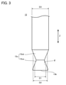
- FIG. 3 is an enlarged view of the coating needle 13 in the vicinity of the lower end 13b.
- the coating needle 13 has a tip portion 13c on the lower end 13b side.
- the tip portion 13c has a first portion 13ca and a second portion 13cc.
- the first portion 13ca is located at the lower end 13b.
- the second portion 13cab is adjacent to the first portion 13ca on the opposite side of the lower end 13b.
- the outer diameter of the first part 13ca is defined as the outer diameter D1.
- the outer diameter of the second portion 13cc is defined as the outer diameter D2.
- the outer diameter D1 becomes smaller as the distance from the lower end 13b increases.
- the outer diameter D1 at the end on the second portion 13cab side is equal to the outer diameter D2 at the end on the first portion 13ca side.
- the outer diameter D2 increases as the distance from the first portion 13ca increases. That is, the tip portion 13c has a constricted shape between the lower end 13b and the end opposite to the lower end 13b.
- the outer diameter of the portion of the coating needle 13 adjacent to the tip portion 13c is defined as the outer diameter D3.
- the angle formed by the side surface of the first portion 13ca and the vertical direction is defined as an angle ⁇ .
- FIG. 4 is a cross-sectional view of the container 14 parallel to the Z axis.
- the container 14 has an upper end 14a and a lower end 14b.
- the lower end 14b is the opposite end of the upper end 14a.
- the inside of the container 14 is hollow.
- An opening 14c is formed at the upper end 14a.
- the opening 14c communicates with the internal space of the container 14.
- the lower end 14b is closed by the bottom wall 14d.
- a hole 14e is formed in the bottom wall 14d.
- the hole 14e penetrates the bottom wall 14d in the thickness direction and communicates with the internal space of the container 14.
- the liquid material L is stored in the internal space of the container 14.
- the tip portion 13c is inserted into the internal space of the container 14 through the opening portion 14c.
- the cam 112 rotates with the rotation of the rotation shaft 111a. Since the distance between the outer peripheral portion of the second surface 112b and the first surface 112a varies, the position of the bearing 113 in the vertical direction changes due to the rotation of the cam 112. As described above, the movable portion 115 is connected to the bearing 113 by the cam connecting plate 114, and the coating needle holder 12 is attached to the movable portion 115. Therefore, the position of the bearing 113 in the vertical direction fluctuates, so that the position of the coating needle 13 held by the coating needle holder 12 in the vertical direction fluctuates. In this way, the drive mechanism 11 moves the position of the coating needle 13 (tip portion 13c) in the vertical direction.
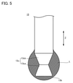
- FIG. 5 is a first schematic diagram showing the relationship between the angle ⁇ and the adhesion mode of the liquid material L.
- FIG. 6 is a second schematic diagram showing the relationship between the angle ⁇ and the adhesion mode of the liquid material L. As shown in FIGS. 5 and 6, by changing the angle ⁇ , the mode of adhesion of the liquid material L to the tip portion 13c changes.
- the angle ⁇ When the angle ⁇ is relatively large, the liquid material L adheres so as to cover the tip portion 13c. On the other hand, when the angle ⁇ is relatively small, the liquid material L does not adhere to the side surface of the tip portion 13c, but adheres to the lower end portion 13b so as to hang down.
- the liquid material L for example, the liquid material L1 is stored in the internal space of the container 14 in the coating mechanism 10A. Further, the liquid material L2 is stored as the liquid material L in the internal space of the container 14 in the coating mechanism 10B.
- the liquid material L1 and the liquid material L2 are, for example, different liquid materials from each other.
- the liquid material L1 and the liquid material L2 may be, for example, a two-component adhesive.
- the angle ⁇ may be an angle at which the liquid material L1 adheres so as to cover the tip portion 13c when the tip portion 13c protrudes from the hole 14e. Further, in the coating mechanism 10B, the angle ⁇ may be an angle at which the liquid material L2 hangs down from the lower end 13b when the tip portion 13c protrudes from the hole 14e.
- the control device 30 When the liquid material L is to be applied onto the substrate SUB, the control device 30 first receives the X-axis stage 22 via the electrical box 27 so that the coated position of the substrate SUB is located directly below the observation optical system 28. And the Y-axis stage 23 is driven. Next, the observation optical system 28 and the image pickup apparatus 29 observe and confirm the coated position of the substrate SUB, and the coated position of the substrate SUB is determined based on the observation and confirmation results. Further, the Z-axis stage 26 and the coating mechanism 10 (drive mechanism 11) are driven based on the coating command input to the control device 30 via the keyboard 30c and the mouse 30d.
- the tip portion 13c to which the liquid material L is attached protrudes from the hole 14e, the liquid material L comes into contact with the coated position of the substrate SUB, and the liquid material L is applied to the substrate SUB.
- the operation of the coating device 100 is not limited to the above.
- the coating device 100 may automatically coat the liquid material L at a predetermined position of the substrate SUB, for example.
- the liquid material L1 is stored in the internal space of the container 14 in the coating mechanism 10A
- the liquid material L2 is stored in the internal space of the container 14 in the coating mechanism 10B
- the liquid material L1 and the liquid material L2 are two-component.
- the coating device 100 may cause the coating mechanism 10A to perform the above coating operation, and then the coating mechanism 10B may perform the above coating operation at the same position.
- coating device 100A The configuration of the coating device 100 (hereinafter referred to as “coating device 100A”) according to the comparative example excludes the detailed configuration of the coating needle 13 (the coating needle 13 in the coating device 100A, hereinafter referred to as “coating needle 13A”). ”), which is common to the configuration of the coating device 100.
- FIG. 7 is an enlarged view of the coating needle 13A in the vicinity of the lower end 13b. As shown in FIG. 7, in the coating needle 13A, the outer diameter of the tip portion 13c is the outer diameter D4. The outer diameter D4 increases monotonically as the distance from the lower end 13b increases. The outer diameter of the portion of the coating needle 13A adjacent to the tip portion 13c is defined as the outer diameter D5.
- the outer diameter D4 at the end opposite to the lower end 13b coincides with the outer diameter D5, and the outer diameter D4 increases monotonically as the distance from the lower end 13b increases. If the diameter D4 is to be increased, the outer diameter D5 must be increased. As a result, the inner diameter of the hole 14e must also be increased.
- the outer diameter D1 at the lower end 13b can be determined independently of the outer diameter D3 as long as it is within the range of the outer diameter D3 or less. Therefore, when the outer diameter D1 at the lower end 13b of the coating needle 13 and the outer diameter D4 at the lower end 13b of the coating needle 13A are made equal, the outer diameter D3 of the coating needle 13 may be made smaller than the outer diameter D5 of the coating needle 13A. It will be possible. As a result, in the coating device 100, even if the outer diameter D1 at the lower end 13b of the coating needle 13 and the outer diameter D4 at the lower end 13b of the coating needle 13A are the same, the inner diameter of the hole 14e can be made smaller than that of the coating device 100A. can.
- the container 14 Since the container 14 is held so that the liquid material L does not leak from the hole 14e due to the surface tension of the liquid material L, when the inner diameter of the hole 14e becomes large, the liquid material L tends to accumulate in the hole 14e and the coating is stable. The sex may be impaired. As described above, according to the coating device 100, it is possible to avoid expanding the diameter of the hole 14e as the inner diameter of the tip portion 13c at the lower end 13b is increased, so that the stability of coating can be improved.
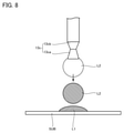
- FIG. 8 is a schematic view when the liquid material L2 is coated using the coating mechanism 10B.
- the liquid material L1 is applied onto the substrate SUB by the coating mechanism 10A before the liquid material L2 is applied using the coating mechanism 10B.
- the angle ⁇ is such that the liquid material L2 hangs down from the lower end 13b when the tip portion 13c protrudes from the hole 14e.
- the liquid material L2 hanging from the lower end 13b cannot withstand the surface tension and eventually falls on the substrate SUB (on the liquid material L1).
- the liquid material L2 can be coated without the tip portion 13c of the coating mechanism 10B coming into contact with the liquid material L1.
- the coating device 100 it is possible to prevent the tip portion 13c of the coating mechanism 10B from coming into contact with the liquid material L1 and, by extension, the adhesive from solidifying at the tip portion 13c of the coating mechanism 10B, thus improving the stability of coating. can do.
- the above embodiment is particularly advantageously applied to a liquid material coating mechanism and coating apparatus.
Landscapes
- Coating Apparatus (AREA)
Abstract
塗布機構は、上下方向において第1上端と第1上端の反対側の端である第1下端とを有し、液体材料が貯留される容器と、上下方向に沿って延在しており、上下方向において第2上端と第2上端の反対側の端である第2下端とを有する塗布針と、塗布機構とを備えている。容器の第1上端には、開口部が形成されている。容器は、第1下端を閉塞し、孔が形成された底壁を含んでいる。塗布針は、第2下端に位置する第1部分と上下方向において第1部分に隣接する第2部分とを含む先端部を有し、先端部が開口部から容器の内部に挿入されている。第1部分の外径は第2下端から離れるにしたがって小さくなっており、第2部分の外径は第1部分から離れるにしたがって大きくなっている。塗布機構は、塗布針を上下方向に沿って移動させることにより、先端部を孔から突出させる。
Description
本発明は、塗布装置及び塗布機構に関する。
特許文献1(特開2015-112576号公報)には、塗布機構が記載されている。特許文献1に記載されている塗布機構は、塗布材料容器と、塗布針と、駆動機構とを有している。
塗布材料容器は、上下方向において、第1上端と、第1上端の反対側の端である第1下端とを有している。塗布材料容器の第1下端は、底壁により閉塞されている。底壁には、塗布材料容器の内部に連通している孔が形成されている。塗布材料容器の第1上端には、塗布材料容器の内部に連通している開口部が形成されている。塗布材料容器の内部には、液体材料が貯留されている。
塗布針は、上下方向に延在している。塗布針は、上下方向において、第2上端と、第2上端の反対側の端である第2下端とを有している。塗布針は、第2下端に位置する先端部を有している。先端部の外径は、第2下端から離れるにしたがって大きくなっている。先端部は、開口部から塗布材料容器の内部に挿入されている。
駆動機構は、塗布針を上下方向に沿って移動させる。これにより、先端部が、孔から突出する。先端部が孔から突出する際、液体材料が、先端部に付着している。先端部に付着している液体材料は、基板上に塗布される。
特許文献1に記載されている塗布機構においては、先端部の外径が第2下端から離れるにしたがって大きくなっているため、上下方向において先端部に隣接する塗布針の部分の外径は、先端部の外径よりも大きくなる。その結果、特許文献1に記載されている塗布機構においては、塗布針を孔に通過させるために、孔の内径を大きくせざるを得ない。孔の内径が大きくなると、孔の内部に液体材料が溜まりやすくなり、液体材料の塗布の安定性が損なわれるおそれがある。
本発明は、上記のような従来技術の問題点に鑑みてなされたものである。より具体的には、本発明は、液体材料の塗布の安定性を改善することが可能な塗布機構及び塗布装置を提供するものである。
本発明の塗布機構は、上下方向において第1上端と第1上端の反対側の端である第1下端とを有し、内部に液体材料が貯留される容器と、上下方向に沿って延在しており、上下方向において第2上端と第2上端の反対側の端である第2下端とを有する塗布針と、塗布機構とを備える。容器の第1上端には、容器の内部に連通している開口部が形成されている。容器は、第1下端を閉塞し、容器の内部に連通している孔が形成された底壁を含んでいる。塗布針は、第2下端に位置する第1部分と上下方向において第1部分に隣接する第2部分とを含む先端部を有し、先端部が開口部から容器の内部に挿入されている。第1部分の外径は、第2下端から離れるにしたがって小さくなっている。第2部分の外径は、第1部分から離れるにしたがって大きくなっている。塗布機構は、塗布針を上下方向に沿って移動させることにより、先端部を孔から突出させる。
上記の塗布機構において、第1部分の側面と上下方向とは、先端部が孔から突出した際に液体材料が第2下端から垂れ下がるような角度をなしていてもよい。
上記の塗布機構において、第1部分の側面と上下方向とは、先端部が孔から突出した際に液体材料が先端部を覆うような角度をなしていてもよい。
本発明の塗布装置は、少なくとも1つの上記の塗布機構を備える。
上記の塗布装置において、塗布機構の数は、複数であってもよい。複数の塗布機構のうちの1つにおいては、容器の内部に液体材料として第1液体材料が貯留されているとともに、第1部分の側面と上下方向とが先端部が孔から突出した際に第1液体材料が先端部を覆うような角度をなしていてもよい。複数の塗布機構のうちの他の1つにおいては、容器の内部に液体材料として第2液体材料が貯留されているとともに、第1部分の側面と上下方向とが先端部が孔から突出した際に第2液体材料が第2下端から垂れ下がるような角度をなしていてもよい。
上記の塗布装置において、塗布機構の数は、複数であってもよい。複数の塗布機構のうちの1つにおいては、容器の内部に液体材料として第1液体材料が貯留されているとともに、第1部分の側面と上下方向とが先端部が孔から突出した際に第1液体材料が先端部を覆うような角度をなしていてもよい。複数の塗布機構のうちの他の1つにおいては、容器の内部に液体材料として第2液体材料が貯留されているとともに、第1部分の側面と上下方向とが先端部が孔から突出した際に第2液体材料が第2下端から垂れ下がるような角度をなしていてもよい。
本発明の塗布機構及び塗布装置によると、液体材料の塗布の安定性を改善することができる。
本発明の実施形態の詳細を、図面を参照しながら説明する。以下の図面においては、同一又は相当する部分に同一の参照符号を付し、重複する説明は繰り返さない。
(実施形態に係る塗布装置の構成)
以下に、実施形態に係る塗布装置(以下においては、「塗布装置100」とする)の構成を説明する。
以下に、実施形態に係る塗布装置(以下においては、「塗布装置100」とする)の構成を説明する。
図1は、塗布装置100の斜視図である。図1に示されるように、塗布装置100は、塗布機構10と、ベース板21a及び架台21bと、X軸ステージ22と、Y軸ステージ23と、ステージ可動板24と、吸着板25と、Z軸ステージ26と、電装ボックス27と、観察光学系28と、撮像装置29と、制御装置30とを有している。塗布機構10の数は、少なくとも1つである。図1に示される例においては、塗布機構10の数は、2つである(以下においては、これらの塗布機構10を、それぞれ、「塗布機構10A」及び「塗布機構10B」とすることがある)。
ベース板21a上には、X軸ステージ22が配置されている。X軸ステージ22は、可動部を有しており、可動部をX軸方向に沿って移動させる。ベース板21aには、架台21bが取り付けられている。X軸ステージ22の可動部上には、Y軸ステージ23が配置されている。Y軸ステージ23は、可動部を有しており、可動部をY軸方向に沿って移動させる。なお、Y軸は、X軸に直交している。
Y軸ステージ23の可動部上には、ステージ可動板24が配置されている。ステージ可動板24上には、吸着板25が配置されている。吸着板25上には、基板SUBが配置されている。基板SUBは、吸着板25に吸着されることにより、位置が固定されている。X軸ステージ22の可動部及びY軸ステージ23の可動部が移動されることにより、基板SUBのX軸及びY軸に沿う方向における位置が変化される。
Z軸ステージ26は、架台21bに取り付けられている。Z軸ステージ26は、可動部を有しており、可動部をZ軸に沿って移動させる。なお、Z軸は、X軸及びY軸に直交しており、鉛直方向に対応している。また、Z軸は、基板SUBの主面に直交している。
Z軸ステージ26の可動部には、塗布機構10が取り付けられている。Z軸ステージ26の可動部が移動されることにより、塗布機構10のZ軸に沿う方向における位置が変化される。撮像装置29は、観察光学系28を介して、基板SUBを観察可能である。撮像装置29は、例えば、CCD(Charge Coupled Device)カメラである。
電装ボックス27は、X軸ステージ22、Y軸ステージ23及びZ軸ステージ26並びに塗布機構10に接続されている。電装ボックス27には、X軸ステージ22、Y軸ステージ23及びZ軸ステージ26並びに塗布機構10を駆動するための電装部品が格納されている。
制御装置30は、例えば、コンピュータ30aと、モニタ30bと、キーボード30cと、マウス30dとを有している。
コンピュータ30aは、例えばパソコンである。コンピュータ30aは、電装ボックス27(より具体的には、電装ボックス27内に格納されている各電装部品)に接続されており、電装ボックス27に対してX軸ステージ22、Y軸ステージ23及びZ軸ステージ26並びに塗布機構10を駆動させるための制御信号を送出する。
モニタ30bは、コンピュータ30aに接続されている。モニタ30bには、撮像装置29により撮影された画像及びコンピュータ30aの操作画面が表示される。キーボード30c及びマウス30dは、コンピュータ30aに接続されている。モニタ30bに表示されている操作画面上においてキーボード30c及びマウス30dを用いて各種の入力を行うことにより、コンピュータ30aから、電装ボックス27に対する制御信号が送出される。
<塗布機構10の詳細>
図2は、塗布機構10の正面図である。図2に示されるように、塗布機構10は、駆動機構11と、塗布針ホルダ12と、塗布針13と、容器14とを有している。
図2は、塗布機構10の正面図である。図2に示されるように、塗布機構10は、駆動機構11と、塗布針ホルダ12と、塗布針13と、容器14とを有している。
駆動機構11は、例えば、サーボモータ111と、カム112と、軸受113と、カム連結板114と、可動部115とを有している。
サーボモータ111は、回転軸111aを有している。回転軸111aは、Z軸に沿って延在している。サーボモータ111は、図示されていないが、電装ボックス27に接続されている。サーボモータ111は、回転軸111aを中心軸回りに回転させる。カム112は、第1面112aと、第2面112bとを有している。第1面112aは、下方を向いている。第2面112bは、上方を向いている。すなわち、第2面112bは、第1面112aの反対面である。
第2面112bは、中央部と、外周部とを有している。カム112は、第2面112bの中央部において、回転軸111aに取り付けられている。第2面112bの外周部は、第2面112bの中央部の周囲に位置している。第2面112bの外周部と第1面112aとの間の距離は、周方向(回転軸111aの中心軸を中心とする円周に沿う方向)に沿って変動している。第2面112bの外周部は、カム112のカム面となっている。
軸受113は、その外周面がカム112のカム面(第2面112bの外周部)に接触するように配置されている。カム連結板114は、一方端において軸受113に連結されており、他方端において可動部115に連結されている。
塗布針ホルダ12は、可動部115に取り付けられている。塗布針13は、Z軸に沿う方向(上下方向)に沿って延在している。塗布針13は、上端13aと、下端13bとを有している。下端13bは、上端13aの反対側の端である。塗布針13の上端13a側は、塗布針ホルダ12により保持されている。
図3は、下端13b近傍における塗布針13の拡大図である。図3に示されるように、塗布針13は、下端13b側に、先端部13cを有している。先端部13cは、第1部分13caと、第2部分13cbとを有している。第1部分13caは、下端13bに位置している。第2部分13cbは、下端13bとは反対側において第1部分13caに隣接している。
第1部分13caの外径を、外径D1とする。第2部分13cbの外径を、外径D2とする。外径D1は、下端13bから離れるにしたがって小さくなっている。第2部分13cb側の端における外径D1は、第1部分13ca側の端における外径D2に等しい。外径D2は、第1部分13caから離れるにしたがって大きくなっている。すなわち、先端部13cは、下端13bと下端13bとは反対側の端との間においてくびれた形状を有している。先端部13cに隣接する塗布針13の部分の外径を、外径D3とする。第1部分13caの側面と上下方向とがなす角度を、角度θとする。
図4は、Z軸に平行な容器14の断面図である。図4に示されるように、容器14は、上端14aと、下端14bとを有している。下端14bは、上端14aの反対側の端である。容器14の内部は、中空になっている。上端14aには、開口部14cが形成されている。開口部14cは、容器14の内部空間に連通している。下端14bは、底壁14dにより閉塞されている。底壁14dには、孔14eが形成されている。孔14eは、底壁14dを厚さ方向に貫通し、容器14の内部空間に連通している。容器14の内部空間には、液体材料Lが貯留される。先端部13cは、開口部14cから容器14の内部空間に挿入されている。
回転軸111aの回転に伴って、カム112が回転する。第2面112bの外周部と第1面112aとの間の距離は変動しているため、カム112が回転することにより、軸受113の上下方向における位置が変動する。上記のとおり、可動部115はカム連結板114により軸受113に連結されており、塗布針ホルダ12は可動部115に取り付けられている。そのため、軸受113の上下方向における位置が変動することにより、塗布針ホルダ12により保持されている塗布針13の上下方向における位置が変動する。このようにして、駆動機構11は、塗布針13(先端部13c)の上下方向における位置を移動させる。
駆動機構11が塗布針13を下方に移動させることにより、先端部13cが、孔14eから突出する。この突出に伴い、先端部13cには、液体材料Lが付着する。図5は、角度θと液体材料Lの付着態様との関係を示す第1模式図である。図6は、角度θと液体材料Lの付着態様との関係を示す第2模式図である。図5及び図6に示されるように、角度θを変化させることにより、液体材料Lの先端部13cへの付着態様は、変化する。
角度θが相対的に大きい場合、液体材料Lは、先端部13cを覆うように付着する。他方で、角度θが相対的に小さい場合、液体材料Lは、先端部13cの側面には付着せず、下端13bに垂れ下がるように付着する。なお、図5に示される状態から図6に示される状態へと付着の態様が変化する角度θは、液体材料Lの粘度により変化することになる。
塗布機構10Aにおける容器14の内部空間には、液体材料Lとして、例えば液体材料L1が貯留される。また、塗布機構10Bにおける容器14の内部空間には、液体材料Lとして、液体材料L2が貯留される。液体材料L1及び液体材料L2は、例えば、互いに異なる液体材料である。液体材料L1及び液体材料L2は、例えば、2液性の接着剤であってもよい。
塗布機構10Aにおいて、角度θは、先端部13cが孔14eから突出した際に液体材料L1が先端部13cを覆うように付着する角度になっていてもよい。また、塗布機構10Bにおいて、角度θは、先端部13cが孔14eから突出した際に液体材料L2が下端13bから垂れ下がるように付着する角度になっていてもよい。
(実施形態に係る塗布装置の動作)
以下に、塗布装置100の動作を説明する。
以下に、塗布装置100の動作を説明する。
液体材料Lを基板SUB上に塗布しようとする際、制御装置30は、まず、基板SUBの被塗布位置が観察光学系28の直下に位置するように、電装ボックス27を介してX軸ステージ22及びY軸ステージ23を駆動させる。次に、観察光学系28及び撮像装置29により、基板SUBの被塗布位置が観察及び確認されるとともに、その観察及び確認の結果に基づいて、基板SUBの被塗布位置が決定される。さらに、キーボード30c及びマウス30dを介して制御装置30に入力された塗布指令に基づいてZ軸ステージ26及び塗布機構10(駆動機構11)が駆動される。
その結果、液体材料Lの付着した先端部13cが孔14eから突出するとともに、液体材料Lが基板SUBの被塗位置に接触し、液体材料Lの基板SUBへの塗布が行われる。なお、塗布装置100の動作は、上記のものに限られない。塗布装置100は、例えば、予め定められた基板SUBの位置に自動で液体材料Lの塗布を行ってもよい。
塗布機構10Aにおける容器14の内部空間に液体材料L1が貯留されており、塗布機構10Bにおける容器14の内部空間に液体材料L2が貯留されており、かつ液体材料L1及び液体材料L2が2液性の接着剤である場合、塗布装置100が塗布機構10Aに対して上記の塗布動作を行わせた後に、同一位置において塗布機構10Bに上記の塗布動作を行わせればよい。
(実施形態に係る塗布装置の効果)
以下に、塗布装置100の効果を、比較例と対比しながら説明する。
以下に、塗布装置100の効果を、比較例と対比しながら説明する。
比較例に係る塗布装置100(以下においては、「塗布装置100A」とする)の構成は、塗布針13の詳細な構成を除き(塗布装置100Aにおける塗布針13を、以下においては「塗布針13A」とする)、塗布装置100の構成と共通している。図7は、下端13b近傍における塗布針13Aの拡大図である。図7に示されるように、塗布針13Aにおいて、先端部13cの外径は、外径D4になっている。外径D4は、下端13bから離れるにしたがって、単調に増加している。先端部13cに隣接している塗布針13Aの部分の外径を、外径D5とする。
塗布針13Aにおいて、下端13bとは反対側の端における外径D4が外径D5に一致しているとともに、外径D4が下端13bから離れるにしたがって単調に増加しているため、下端13bにおける外径D4を大きくしようとすると、外径D5を大きくせざるを得ない。その結果、孔14eの内径も、大きくせざるを得ない。
塗布針13において、下端13bにおける外径D1は、外径D3以下の範囲内であれば外径D3とは無関係に決定することができる。そのため、塗布針13の下端13bにおける外径D1と塗布針13Aの下端13bにおける外径D4とを等しくする場合、塗布針13の外径D3を塗布針13Aの外径D5よりも小さくすることが可能になる。その結果、塗布装置100においては、塗布針13の下端13bにおける外径D1と塗布針13Aの下端13bにおける外径D4とが同一でも、孔14eの内径を、塗布装置100Aよりも小さくすることができる。
容器14は、液体材料Lの表面張力により液体材料Lが孔14eから漏れないように保持されているため、孔14eの内径が大きくなると、孔14eに液体材料Lが溜まりやくなり、塗布の安定性が損なわれるおそれがある。このように、塗布装置100によると、下端13bにおける先端部13cの内径を大きくするに伴って孔14eを拡径することを回避できるため、塗布の安定性を改善することができる。
図8は、塗布機構10Bを用いて液体材料L2の塗布を行う際の模式図である。図8に示されるように、塗布機構10Bを用いた液体材料L2の塗布が行われる前に、塗布機構10Aにより、液体材料L1が基板SUB上に塗布されている。塗布機構10Bにおいては、角度θが、孔14eから先端部13cが突出した際に液体材料L2が下端13bから垂れ下がるように付着する角度になっている。下端13bから垂れ下がっている液体材料L2は、表面張力に耐え切れなくなり、やがては基板SUB上(液体材料L1上)に落下する。このように、塗布装置100によると、塗布機構10Bの先端部13cが液体材料L1に接触することなく、液体材料L2の塗布を行うことができる。
先端部13cにおいて接着剤が固まってしまうと、塗布を繰り返すうちに先端部13cが太くなってしまい、液体材料L2の塗布量が増加する。また、接着剤が固まることにより先端部13cが太くなると、最終的には、孔14eに通らなくなる。塗布装置100によると、塗布機構10Bの先端部13cが液体材料L1に接触すること、ひいては、塗布機構10Bの先端部13cにおいて接着剤が固まってしまうことを抑制できるため、塗布の安定性を改善することができる。
以上のように本発明の実施形態について説明を行ったが、上述の実施形態を様々に変形することも可能である。また、本発明の範囲は、上述の実施形態に限定されるものではない。本発明の範囲は、請求の範囲によって示され、請求の範囲と均等の意味及び範囲内での全ての変更を含むことが意図される。
上記の実施形態は、液体材料の塗布機構及び塗布装置に特に有利に適用される。
10,10A,10B 塗布機構、11 駆動機構、12 塗布針ホルダ、13,13A 塗布針、13a 上端、13b 下端、13c 先端部、13ca 第1部分、13cb 第2部分、14 容器、14a 上端、14b 下端、14c 開口部、14d 底壁、14e 孔、21a ベース板、21b 架台、22 X軸ステージ、23 Y軸シテージ、24 ステージ可動板、25 吸着板、26 軸ステージ、27 電装ボックス、28 観察光学系、29 撮像装置、30 制御装置、30a コンピュータ、30b モニタ、30c キーボード、30d マウス、100,100A 塗布装置、111 サーボモータ、111a 回転軸、112 カム、112a 第1面、112b 第2面、113 軸受、114 カム連結板、115 可動部、D1,D2,D3,D4,D5 外径、L,L1,L2 液体材料、SUB 基板。
Claims (5)
- 上下方向において第1上端と前記第1上端の反対側の端である第1下端とを有し、内部に液体材料が貯留される容器と、
前記上下方向に沿って延在しており、前記上下方向において第2上端と前記第2上端の反対側の端である第2下端とを有する塗布針と、
塗布機構とを備え、
前記容器の前記第1上端には、前記容器の前記内部に連通している開口部が形成されており、
前記容器は、前記第1下端を閉塞し、前記容器の前記内部に連通している孔が形成された底壁を含み、
前記塗布針は、前記第2下端に位置する第1部分と前記上下方向において前記第1部分に隣接する第2部分とを含む先端部を有し、前記先端部が前記開口部から前記容器の前記内部に挿入されており、
前記第1部分の外径は、前記第2下端から離れるにしたがって小さくなっており、
前記第2部分の外径は、前記第1部分から離れるにしたがって大きくなっており、
前記塗布機構は、前記塗布針を前記上下方向に沿って移動させることにより、前記先端部を前記孔から突出させる、塗布機構。 - 前記第1部分の側面と前記上下方向とは、前記先端部が前記孔から突出した際に前記液体材料が前記第2下端から垂れ下がるような角度をなしている、請求項1に記載の塗布機構。
- 前記第1部分の側面と前記上下方向とは、前記先端部が前記孔から突出した際に前記液体材料が前記先端部を覆うような角度をなしている、請求項1に記載の塗布機構。
- 少なくとも1つの請求項1に記載の前記塗布機構を備える、塗布装置。
- 前記塗布機構の数は、複数であり、
複数の前記塗布機構のうちの1つにおいては、前記容器の前記内部に前記液体材料として第1液体材料が貯留されているとともに、前記第1部分の側面と前記上下方向とが前記先端部が前記孔から突出した際に前記第1液体材料が前記先端部を覆うような角度をなしており、
複数の前記塗布機構のうちの他の1つにおいては、前記容器の前記内部に前記液体材料として第2液体材料が貯留されているとともに、前記第1部分の側面と前記上下方向とが前記先端部が前記孔から突出した際に前記第2液体材料が前記第2下端から垂れ下がるような角度をなしている、請求項4に記載の塗布装置。
Applications Claiming Priority (2)
| Application Number | Priority Date | Filing Date | Title |
|---|---|---|---|
| JP2020-121373 | 2020-07-15 | ||
| JP2020121373A JP7362556B2 (ja) | 2020-07-15 | 2020-07-15 | 塗布機構及び塗布装置 |
Publications (1)
| Publication Number | Publication Date |
|---|---|
| WO2022014642A1 true WO2022014642A1 (ja) | 2022-01-20 |
Family
ID=79554655
Family Applications (1)
| Application Number | Title | Priority Date | Filing Date |
|---|---|---|---|
| PCT/JP2021/026472 Ceased WO2022014642A1 (ja) | 2020-07-15 | 2021-07-14 | 塗布機構及び塗布装置 |
Country Status (2)
| Country | Link |
|---|---|
| JP (1) | JP7362556B2 (ja) |
| WO (1) | WO2022014642A1 (ja) |
Citations (7)
| Publication number | Priority date | Publication date | Assignee | Title |
|---|---|---|---|---|
| JP2008296149A (ja) * | 2007-05-31 | 2008-12-11 | Ntn Corp | 塗布機構およびそれを用いた欠陥修正装置 |
| JP2010062385A (ja) * | 2008-09-04 | 2010-03-18 | Ntn Corp | フラックス塗布装置およびフラックス塗布方法 |
| JP2012101175A (ja) * | 2010-11-10 | 2012-05-31 | Ntn Corp | 塗布機構、塗布方法、および塗布装置 |
| JP2017000947A (ja) * | 2015-06-09 | 2017-01-05 | Ntn株式会社 | 塗布ユニットおよびそれを用いた塗布装置 |
| JP2017094287A (ja) * | 2015-11-25 | 2017-06-01 | Ntn株式会社 | 塗布ユニット、塗布装置、被塗布対象物の製造方法および基板の製造方法 |
| JP2017225923A (ja) * | 2016-06-22 | 2017-12-28 | パイオニア株式会社 | 塗布装置、制御方法及びプログラム |
| JP2019209301A (ja) * | 2018-06-08 | 2019-12-12 | 国立大学法人大阪大学 | 塗布ユニットおよび微細塗布装置 |
-
2020
- 2020-07-15 JP JP2020121373A patent/JP7362556B2/ja active Active
-
2021
- 2021-07-14 WO PCT/JP2021/026472 patent/WO2022014642A1/ja not_active Ceased
Patent Citations (7)
| Publication number | Priority date | Publication date | Assignee | Title |
|---|---|---|---|---|
| JP2008296149A (ja) * | 2007-05-31 | 2008-12-11 | Ntn Corp | 塗布機構およびそれを用いた欠陥修正装置 |
| JP2010062385A (ja) * | 2008-09-04 | 2010-03-18 | Ntn Corp | フラックス塗布装置およびフラックス塗布方法 |
| JP2012101175A (ja) * | 2010-11-10 | 2012-05-31 | Ntn Corp | 塗布機構、塗布方法、および塗布装置 |
| JP2017000947A (ja) * | 2015-06-09 | 2017-01-05 | Ntn株式会社 | 塗布ユニットおよびそれを用いた塗布装置 |
| JP2017094287A (ja) * | 2015-11-25 | 2017-06-01 | Ntn株式会社 | 塗布ユニット、塗布装置、被塗布対象物の製造方法および基板の製造方法 |
| JP2017225923A (ja) * | 2016-06-22 | 2017-12-28 | パイオニア株式会社 | 塗布装置、制御方法及びプログラム |
| JP2019209301A (ja) * | 2018-06-08 | 2019-12-12 | 国立大学法人大阪大学 | 塗布ユニットおよび微細塗布装置 |
Also Published As
| Publication number | Publication date |
|---|---|
| JP7362556B2 (ja) | 2023-10-17 |
| JP2022018330A (ja) | 2022-01-27 |
Similar Documents
| Publication | Publication Date | Title |
|---|---|---|
| CN110296814B (zh) | 折叠测试设备 | |
| WO2017090381A1 (ja) | 塗布ユニット、塗布装置、被塗布対象物の製造方法および基板の製造方法 | |
| TW201711757A (zh) | 塗佈單元及使用此單元之塗佈裝置 | |
| EP3451057A1 (en) | Image pickup apparatus | |
| KR20110068419A (ko) | 카메라모듈 | |
| CN107450113A (zh) | 一种镜片及其加工方法、镜头组件 | |
| CN101047090A (zh) | 图形修正装置及其涂布单元 | |
| US7361905B2 (en) | Substrate processing apparatus and maintenance method therefor | |
| JP7362556B2 (ja) | 塗布機構及び塗布装置 | |
| WO2015087899A1 (ja) | 塗布部材および塗布装置 | |
| US11511311B2 (en) | Application mechanism and application apparatus | |
| JP2012101175A (ja) | 塗布機構、塗布方法、および塗布装置 | |
| JP6560108B2 (ja) | 塗布ユニット、塗布装置、被塗布対象物の製造方法および基板の製造方法 | |
| CN113493901A (zh) | 真空镀膜机 | |
| JP2017131826A (ja) | 塗布機構、塗布装置、被塗布対象物の製造方法、および基板の製造方法 | |
| JP2009206061A (ja) | 塗布ユニットおよびそれを用いたパターン修正装置 | |
| JP2020112744A (ja) | 撮像装置および該撮像装置に用いられる封止部材 | |
| JP6835506B2 (ja) | 液体塗布ユニットおよび液体塗布装置 | |
| JP2021073093A (ja) | 液体塗布ユニットおよび液体塗布装置 | |
| EP4219022B1 (en) | Liquid application unit and liquid application apparatus | |
| CN210122962U (zh) | 底座结构及风扇 | |
| WO2018235528A1 (ja) | 塗布ユニットおよび塗布装置 | |
| JP2017094287A (ja) | 塗布ユニット、塗布装置、被塗布対象物の製造方法および基板の製造方法 | |
| JP2018034124A (ja) | 液体塗布ユニットおよび液体塗布装置 | |
| JP6986502B2 (ja) | 塗布材料収容ユニット、塗布針ユニット、および塗布装置 |
Legal Events
| Date | Code | Title | Description |
|---|---|---|---|
| 121 | Ep: the epo has been informed by wipo that ep was designated in this application |
Ref document number: 21841828 Country of ref document: EP Kind code of ref document: A1 |
|
| NENP | Non-entry into the national phase |
Ref country code: DE |
|
| 122 | Ep: pct application non-entry in european phase |
Ref document number: 21841828 Country of ref document: EP Kind code of ref document: A1 |