WO2022014357A1 - 路面評価装置および路面評価方法 - Google Patents
路面評価装置および路面評価方法 Download PDFInfo
- Publication number
- WO2022014357A1 WO2022014357A1 PCT/JP2021/025067 JP2021025067W WO2022014357A1 WO 2022014357 A1 WO2022014357 A1 WO 2022014357A1 JP 2021025067 W JP2021025067 W JP 2021025067W WO 2022014357 A1 WO2022014357 A1 WO 2022014357A1
- Authority
- WO
- WIPO (PCT)
- Prior art keywords
- information
- road surface
- vehicle
- roughness
- road
- Prior art date
- Legal status (The legal status is an assumption and is not a legal conclusion. Google has not performed a legal analysis and makes no representation as to the accuracy of the status listed.)
- Ceased
Links
Images



Classifications
-
- G—PHYSICS
- G01—MEASURING; TESTING
- G01C—MEASURING DISTANCES, LEVELS OR BEARINGS; SURVEYING; NAVIGATION; GYROSCOPIC INSTRUMENTS; PHOTOGRAMMETRY OR VIDEOGRAMMETRY
- G01C7/00—Tracing profiles
- G01C7/02—Tracing profiles of land surfaces
- G01C7/04—Tracing profiles of land surfaces involving a vehicle which moves along the profile to be traced
-
- G—PHYSICS
- G08—SIGNALLING
- G08G—TRAFFIC CONTROL SYSTEMS
- G08G1/00—Traffic control systems for road vehicles
Definitions
- the present invention relates to a road surface evaluation device and a road surface evaluation method for evaluating a road surface profile representing an uneven shape of a road surface.
- a road surface profile representing the uneven shape of the road surface of the road on which the vehicle travels is detected based on the lateral (lateral direction with respect to the traveling direction) acceleration measured by an acceleration sensor provided in the vehicle.
- a device is known (see, for example, Patent Document 1).
- the road surface profile detected based on the acceleration measured by the acceleration sensor varies depending on various factors such as the position of the tire on the running road surface and the weather. Therefore, it is not possible to sufficiently evaluate the road surface profile by simply detecting the road surface profile based on the acceleration measured by the acceleration sensor as in the device described in Patent Document 1.
- the road surface evaluation device is a vehicle information acquisition unit that acquires vehicle information including information indicating the movement of a moving vehicle and vehicle position information, and a map including information on the road on which the vehicle travels.
- the map information acquisition unit that acquires information, and the roughness information derivation unit that derives the roughness information indicating the roughness of the road surface and the reliability of the roughness information based on the vehicle information acquired by the vehicle information acquisition unit. It also has an output unit that outputs the roughness information and the reliability derived by the roughness information derivation unit in association with the road information acquired by the map information acquisition unit.
- a step of acquiring vehicle information including information indicating the motion of a moving vehicle and vehicle position information, and map information including information on the road on which the vehicle travels are obtained.
- the step to be acquired, the step to derive the roughness information indicating the roughness of the road surface and the reliability of the roughness information based on the acquired vehicle information, and the derived roughness information and the reliability are acquired. It includes executing a step of outputting in association with the information of the road that has been made by a computer.
- the road surface profile can be sufficiently evaluated.
- FIG. 5 is a diagram showing an example of vehicle information acquired by a road surface evaluation device from an in-vehicle device of a vehicle traveling on the road of FIG. 5A.
- the flowchart which shows an example of the process executed by the arithmetic unit of FIG.
- the figure which shows an example of the information output by the road surface profile output part of FIG.
- the road surface evaluation device is a device for evaluating the road surface profile of the road on which the vehicle travels.
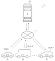
- FIG. 1 is a diagram showing an example of a configuration of a road surface evaluation system including a road surface evaluation device according to the present embodiment.
- the road surface evaluation system 1 includes a road surface evaluation device 10 and an in-vehicle device 30.
- the road surface evaluation device 10 is configured as a server device.
- the in-vehicle device 30 is configured to be able to communicate with the road surface evaluation device 10 via the communication network 2.
- the communication network 2 includes not only public wireless communication networks represented by Internet networks and mobile phone networks, but also closed communication networks provided for each predetermined management area, such as wireless LAN and Wi-Fi (registered trademark). ), Bluetooth®, etc. are also included.
- the in-vehicle device 30 is mounted on various vehicles 20.
- the vehicle 20 includes various vehicles 20-1, 20-2, ..., 20-n having different vehicle widths.
- vehicle 20-1 is a sedan
- vehicle 20-2 is a one-box car with a wider vehicle width than vehicle 20-1
- vehicle 20-n is wider than vehicle 20-1. It is a minivan whose width is narrower than that of vehicle 20-2.
- the vehicle 20 may be a manually driven vehicle or an automatically driven vehicle.
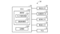
- FIG. 2 is a block diagram showing a configuration of a main part of the in-vehicle device 30 according to the present embodiment.
- the in-vehicle device 30 includes an electronic control unit (ECU) 31, a positioning sensor 32, an acceleration sensor 33, a steering angle sensor 34, a vehicle speed sensor 35, and a TCU (Telematic Control Unit) 36.
- ECU electronice control unit
- TCU Telematic Control Unit
- the positioning sensor 32 is, for example, a GPS sensor, which receives a positioning signal transmitted from a GPS satellite and detects the absolute position (latitude, longitude, etc.) of the vehicle 20.
- the positioning sensor 32 includes not only a GPS sensor but also a sensor for positioning using radio waves transmitted from satellites of various countries called GNSS satellites such as a quasi-zenith orbit satellite. Further, the vehicle position may be obtained by a hybrid method with inertial navigation.
- the acceleration sensor 33 detects the left-right acceleration of the vehicle 20, that is, the lateral acceleration.
- the acceleration sensor 33 may be configured to detect the lateral acceleration of the vehicle 20 as well as the acceleration in the front-rear direction and the acceleration in the vertical direction.
- the steering angle sensor 34 detects the steering angle of the steering wheel (not shown) of the vehicle 20.
- the vehicle speed sensor 35 detects the vehicle speed of the vehicle 20.
- the ECU 31 includes a computer having a calculation unit 310 such as a CPU, a storage unit 320 such as a ROM and RAM, and other peripheral circuits (not shown) such as an I / O interface. ..
- the calculation unit 310 functions as a sensor value acquisition unit 311 and a communication control unit 312 by executing a program stored in the storage unit 320 in advance.
- the sensor value acquisition unit 311 acquires information (value) detected by each sensor 32 to 35, that is, vehicle information.
- the sensor value acquisition unit 311 acquires vehicle information including the acceleration of the vehicle 20 detected by the acceleration sensor 33 and the absolute position of the vehicle 20 detected by the positioning sensor 32 at a predetermined cycle, for example, every 10 ms.
- the vehicle information includes at least the lateral acceleration of the vehicle 20 detected by the acceleration sensor 33.
- the communication control unit 312 transmits the vehicle information acquired by the sensor value acquisition unit 311 to the road surface evaluation device 10 via the TCU 36 at a predetermined cycle. More specifically, the communication control unit 312 thins out the vehicle information acquired by the sensor value acquisition unit 311 so as not to increase the processing load and unnecessarily press the band of the communication network 2. For example, it is transmitted every 1s.
- the road surface evaluation device 10 detects the uneven shape of the road surface, that is, the road surface profile, based on the detection value of the acceleration sensor 33 of the vehicle 20.
- This detected road surface profile is output to, for example, a terminal owned by a road management company or the like, and is used as reference data when the road management company or the like examines the necessity of repair or the like. That is, the detection value of the accelerometer is used to evaluate the road surface profile.
- the road surface evaluation device is configured as follows so that the road surface profile can be sufficiently evaluated.
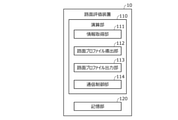
- FIG. 3 is a block diagram showing a main configuration of the road surface evaluation device 10 according to the present embodiment.
- the road surface evaluation device 10 includes a computer having a calculation unit 110 such as a CPU, a storage unit 120 such as a ROM and a RAM, and other peripheral circuits (not shown) such as an I / O interface.
- the storage unit 120 stores map information including a road map and various information processed by the calculation unit 110.
- the calculation unit 110 functions as an information acquisition unit 111, a road surface profile derivation unit 112, a road surface profile output unit 113, and a communication control unit 114 by executing a program stored in the storage unit 120.
- the information acquisition unit 111 acquires vehicle information including the motion of the vehicle 20 including the acceleration in each direction of the vehicle 20 and the position information of the vehicle 20.
- the information acquisition unit 111 receives vehicle information from the vehicle-mounted device 30 of the vehicle 20 traveling on the road via the communication control unit 114.
- the information acquisition unit 111 stores the acquired vehicle information in the storage unit 120 in chronological order.
- the information indicating the motion of the vehicle 20 is information in which information indicating the roll motion of the vehicle, information indicating the motion due to centrifugal force, and information indicating the motion due to the unevenness of the road surface are mixed.
- the information acquisition unit 111 acquires map information including information on the road on which the vehicle 20 travels from the storage unit 120.
- the road surface profile derivation unit 112 derives the amount of unevenness (depth or height) of the road surface, that is, the roughness information indicating the road surface roughness, based on the vehicle information acquired by the information acquisition unit 111. More specifically, the road surface profile derivation unit 112 derives the road surface roughness information by machine learning based on the vehicle information acquired by the information acquisition unit 111.
- the roughness information is a road surface roughness value indicating the degree of road surface roughness, and is, for example, a value represented by IRI (International Roughness Index), which is an international index.
- IRI International Roughness Index
- the road surface profile deriving unit 112 uses this correlation to derive the road surface roughness value corresponding to the vehicle position on the road from the lateral acceleration. Specifically, the road surface profile derivation unit 112 first performs machine learning using the pre-measured road surface roughness value and the lateral acceleration as teacher data, and derives the correlation between the road surface roughness value and the lateral acceleration.
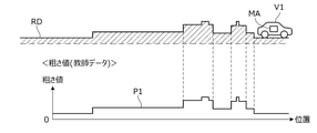
- FIGS. 4A and 4B are diagrams for explaining the teacher data of the road surface roughness value and the lateral acceleration, respectively.
- the vehicle V1 shown in FIG. 4A is a dedicated vehicle equipped with a measuring device MA for measuring road surface roughness.
- the measuring device MA measures the road surface roughness value of the road RD when the vehicle V1 is traveling on a predetermined road (measurement course or the like) RD.
- the characteristic P1 of FIG. 4A shows the road surface roughness value measured at this time.
- FIG. 4B shows how the vehicle 20 of FIG. 1 travels on the same road RD as that of FIG. 4A.
- the characteristic P2 of FIG. 4B shows the lateral acceleration detected every 10 ms by the acceleration sensor 33 provided in the vehicle 20 while the vehicle 20 is traveling on a predetermined road RD.
- the characteristic P1 of FIG. 4A and the characteristic P2 shown in FIG. 4B are used as teacher data when the road surface profile deriving unit 112 derives the correlation between the road surface roughness value and the lateral acceleration, respectively.
- the data of the characteristics P1 and the characteristics P2, that is, the teacher data of the road surface roughness value and the lateral acceleration may be stored in the storage unit 120 of the road surface evaluation device 10 or may be stored in an external storage device.
- the road surface profile deriving unit 112 reads out each teacher data from the storage unit 120 or an external storage device when deriving the correlation between the road surface roughness value and the lateral acceleration.
- the road surface profile derivation unit 112 derives the correlation between the road surface roughness value and the lateral acceleration from the teacher data of the road surface roughness value and the lateral acceleration in advance, and stores the derived correlation information in the storage unit 120 or the like. You may leave it.
- the road surface profile derivation unit 112 may perform machine learning by adding a traveling speed, a longitudinal acceleration, and a steering angle (steering angle) as training data.
- the road surface profile derivation unit 112 uses the correlation between the road surface roughness value and the lateral acceleration, and based on the vehicle information of the vehicle 20 stored in the storage unit 120 in time series, the road surface roughness of the road on which the vehicle 20 travels. Derive the value.
- the vehicle information stored in the storage unit 120 in time series is referred to as time-series vehicle information.
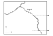
- FIG. 5A is a diagram showing an example of a map of the road on which the vehicle 20 travels.
- FIG. 5A shows a predetermined range (a section of latitudes Y to Z of national highway X) to be derived from the road surface roughness value.
- the upward direction corresponds to the north direction and the right direction corresponds to the east direction.
- the range to be derived from the road surface roughness value can be specified by the user as described later.
- the user specifies the lane to be derived from the road surface roughness value.
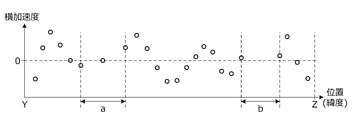
- 5B is a diagram showing an example of time-series vehicle information acquired by the road surface evaluation device 10 from the in-vehicle device 30 of the vehicle 20 traveling in the predetermined range of FIG. 5A (the section of latitude Y to Z of the national highway X). be.
- the horizontal axis in the figure is the position (latitude) in the traveling direction along the traveling lane of the vehicle 20, and the vertical axis is the lateral acceleration of the vehicle 20.
- Vehicle information is transmitted from the communication control unit 312 of the in-vehicle device 30 every predetermined time (1 second in this embodiment). Therefore, as shown in FIG. 5B, the time-series vehicle information of the vehicle 20 becomes discrete information, and a section having a small amount of information is generated. For example, when the traveling speed of the vehicle 20 becomes faster, the distance from the point where the vehicle information was transmitted last time to the point where the vehicle information is transmitted next becomes longer as shown in the section a in the figure, and the amount of information becomes smaller. .. Further, when the road has a plurality of lanes on one side, a section (section b in the figure) in which vehicle information is not transmitted is generated even if the lane is changed.
- the section b is a section in which the vehicle 20 travels in a lane other than the lane designated as the derivation target of the road surface roughness value.
- the road surface profile derivation unit 112 uses the vehicle information acquired in the past from the in-vehicle device 30 of the same vehicle 20 in the section where the amount of information of the vehicle information is small or the section in which the vehicle information is not transmitted, and the road surface is used. Estimate the roughness value. Further, the road surface profile derivation unit 112 estimates the road surface roughness value of the section by using the vehicle information acquired from the vehicle-mounted device 30 of the other vehicle 20 in the section. Further, the road surface profile derivation unit 112 estimates the road surface roughness value of the section in which vehicle information is not acquired from any of the vehicles 20 based on the vehicle information acquired before and after the section.
- the vehicle information is based on the position of the tires and the weather when the vehicle is running. Variation occurs. For example, since the vehicles 20-1, 20-2, and 20-n in FIG. 1 have different vehicle widths, the positions of the tires on which the road surface roughness value is detected are different. Therefore, even when the vehicles 20-1, 20-2, and 20-n travel on the same road, the vehicle information acquired from the in-vehicle device 30 of each vehicle varies. When such a variation occurs, the estimation accuracy of the road surface roughness value fluctuates, and the larger the variation, the lower the estimation accuracy.
- the road surface profile derivation unit 112 is configured to estimate the road surface roughness value by machine learning. More specifically, the road surface profile derivation unit 112 estimates the road surface roughness value by using a complementary algorithm using a Gaussian process, which is a learning method of the Bayesian system.
- the reason for using the Gaussian process is that in the Gaussian process, the estimation accuracy (reliability) of the estimated value can be obtained together with the estimated value.
- the road surface profile output unit 113 outputs the road surface roughness value derived by the road surface profile derivation unit 112 and its reliability in association with the road information acquired by the information acquisition unit 111.
- the communication control unit 114 controls a communication unit (not shown) to transmit / receive data to / from an external device or the like. More specifically, the communication control unit 114 transmits / receives data to / from a terminal such as an in-vehicle device 30 of the vehicle 20 or a road management company via the communication network 2. Further, the communication control unit 114 receives an output instruction of the road surface profile described later from a terminal of a road management company or the like via the communication network 2. Further, the communication control unit 114 acquires map information and the like from various servers connected to the communication network 2 periodically or at an arbitrary timing. The communication control unit 114 stores the information acquired from various servers in the storage unit 120.
- FIG. 6 is a flowchart showing an example of processing executed by the calculation unit 110 (CPU) of the road surface evaluation device 10 according to a predetermined program. The process shown in this flowchart is repeated at a predetermined cycle while the road surface evaluation device 10 is activated.
- step S11 it is determined whether or not the vehicle information is received from the vehicle-mounted device 30 of the vehicle 20. If denied in step S11, the process proceeds to step S13. If affirmed in step S11, the vehicle information received in step S11 is stored in the storage unit 120 in step S12.
- step S13 it is determined whether or not the output instruction of the road surface profile has been input (received).
- the output instruction of the road surface profile is transmitted from a terminal of a user (road management company, etc.) to the road surface evaluation device 10 via the communication network 2, for example.
- the output instruction of the road surface profile may be input to the road surface evaluation device 10 via an operation unit (not shown) included in the road surface evaluation device 10.
- the output instruction of the road surface profile includes section information that can specify the section of the road to be output.
- the section information is information indicating the name and section of the road to be output, such as "road: national highway X, section: latitude Y to Z". If the road has multiple lanes on each side, such as two lanes on each side, the section information includes information on the lane to be output, such as "road: national highway X, lane: right end, section: latitude Y to Z". May be included.
- information other than latitude may be used to specify the section to be output. For example, longitude may be used instead of latitude, or longitude may be used in addition to latitude. Further, the distance from the starting point coordinates may be used.
- step S13 If denied in step S13, the process ends. If affirmed in step S13, the map information is read from the storage unit 120 in step S14, and the road information included in the map information is acquired. In step S15, time-series vehicle information of the vehicle 20 is acquired from the storage unit 120. More specifically, based on the section information included in the output instruction of the road surface profile and the road information acquired in step S14, the time-series vehicle information of the section targeted for output stored in the storage unit 120 is stored. Obtained from unit 120.
- step S17 the road surface roughness value estimated (derived) in step S16 and its reliability are output in association with the road information acquired in step S14. More specifically, based on the road information acquired in step S14, the road surface roughness value estimated in step S16 and the reliability thereof are output in association with each position of the section targeted for output.
- the information output at this time is referred to as road surface profile information.
- the road surface profile information is output via the communication network 2 to the terminal of the transmission source of the output instruction of the road surface profile or the terminal of the predetermined output destination so as to be able to be displayed in the manner shown in FIG.
- the road surface profile information can be displayed on a display device such as a display, and it becomes easy for the user to confirm and evaluate the road surface profile information. Even if it is denied in step S13, if a predetermined amount of time-series vehicle information that has not been output out of the time-series vehicle information of the vehicle 20 stored in the storage unit 120 is accumulated, the process proceeds to step S14. You may try to do it. Even if the affirmation is made in step S13, if the time-series vehicle information of the vehicle 20 stored in the storage unit 120 that is not output is less than a predetermined amount, the process is terminated. May be good. At that time, information (text information, voice information, image information) for notifying that the time-series vehicle information that has not been output is less than a predetermined amount is output to the terminal or the like of the transmission source of the road surface profile output instruction. You may.
- FIG. 7 is a diagram showing an example of road surface profile information output by the road surface profile output unit 113.
- the vertical axis is the road surface roughness value
- the horizontal axis is the position of the vehicle 20.
- the broken line indicates the road surface roughness value (referred to as an estimated roughness value) estimated by the road surface profile deriving unit 112.
- the solid line indicates the actual road surface roughness value (referred to as the actual roughness value). Although the actual roughness value is not included in the road surface profile information, it is displayed in the figure for explanation.
- the region sandwiched between the line L1 and the line L2 indicates the reliability of the estimated roughness value at each position.
- the width CR in the vertical axis direction at the P point indicates the reliability of the estimated roughness value at the P point. show.
- the width CR is a confidence interval of 2 ⁇ when the estimated roughness value follows the Gaussian distribution, and the estimated roughness value at the P point falls within the range with a probability of about 95%. Represents that. That is, the width CR indicates that the narrower the width, the higher the accuracy of the estimated roughness value at that point.
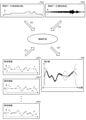
- FIG. 8 is a diagram for explaining data processing in the road surface evaluation device 10 according to the present embodiment.
- the correlation between the road surface roughness value and the lateral acceleration is derived in advance by machine learning ((a), (b)). ..
- each vehicle ran based on the correlation between the road surface roughness value and the lateral acceleration and the time-series vehicle information VD1 to VDn of the vehicles 20-1 to 20-n.
- the road surface roughness value and its reliability are estimated ((c)).
- the estimated road surface roughness value and its reliability are associated with the road information included in the map information read from the storage unit 120, and output as information OD ((d)).
- the road surface evaluation device 10 acquires vehicle information including information indicating the movement of the moving vehicle 20 and position information of the vehicle 20, and information for acquiring map information including information on the road on which the vehicle 20 travels. Based on the vehicle information of the vehicle 20 acquired by the acquisition unit 111 and the information acquisition unit 111, the roughness information indicating the roughness of the road surface on which the vehicle 20 travels and the reliability of the roughness information are derived. Roughness road surface profile derivation unit 112, road surface profile output unit 113 that outputs the roughness information and reliability derived by the road surface profile derivation unit 112 in association with the road information acquired by the information acquisition unit 111. , (Fig. 3).
- the road surface profile of the road can be sufficiently evaluated.
- the evaluation result can be presented to users such as road management companies, the user can guess the road that needs repair without going to the site, and can reduce the cost required for road management. It will be possible.
- the roughness information is a roughness value indicating the degree of roughness of the road surface
- the reliability of the roughness information is a road surface profile based on the vehicle information acquired by the information acquisition unit 111. It is represented by a range of roughness values derived by the derivation unit 112. As a result, the accuracy of the roughness information (roughness value) derived by the road surface profile deriving unit 112 can be recognized, and the road surface profile can be evaluated more sufficiently.
- the road surface profile output unit 113 can display information in which the roughness information derived by the road surface profile derivation unit 112 and the reliability and the road information acquired by the information acquisition unit 111 are associated with each other. As a result, the user can visually recognize the road surface profile of the road, and it becomes easier to guess the road that needs repair.
- the road surface profile derivation unit 112 derives roughness information at each position of the road on which the vehicle travels and the reliability of the roughness information by machine learning using a Gaussian process. As a result, even if the vehicle information acquired by the information acquisition unit 111 is discrete information, the roughness information and the reliability of the roughness information are derived for each position of the road on which the vehicle 20 travels. Is possible.
- the road surface profile derivation unit 112 has the vehicle information corresponding to the first point and the second point. Using the vehicle information corresponding to the point, the roughness information of the third point and the reliability of the roughness information are interpolated and derived. As a result, it is possible to derive the roughness information and the reliability of the roughness information even for the section of the road on which the vehicle has traveled, for which the vehicle information has not been acquired by the information acquisition unit 111.
- the road surface evaluation device 10 of the present embodiment can also be used as a road surface evaluation method.
- a step (step S15) of acquiring vehicle information including information indicating the motion of the moving vehicle 20 and position information of the vehicle 20 and map information including information of the road on which the vehicle travels are acquired.
- Step (step S14) a step (step S16) for deriving the roughness information indicating the roughness of the road surface and the reliability of the roughness information based on the acquired vehicle information, and the derived roughness.
- the step (step S17) of outputting the information and the reliability in association with the acquired road information is included to be executed by a computer (FIG. 6). With this configuration, the road surface profile of the road can be sufficiently evaluated.
- the information acquisition unit 111 acquires the lateral acceleration of the vehicle 20 detected by the acceleration sensor 33 as the vehicle information acquisition unit as information indicating the motion of the vehicle 20, but shows the motion of the vehicle 20.
- the information is not limited to the lateral acceleration of the vehicle 20 detected by the acceleration sensor. That is, as long as the information indicating the motion of the vehicle 20 is acquired, the configuration of the information acquisition unit 111 may be anything such as detecting the longitudinal acceleration of the vehicle 20 by the acceleration sensor.
- the information acquisition unit 111 acquires map information including information on the road on which the vehicle 20 travels as a map information acquisition unit from the storage unit 120, but the map information can be obtained from an external server or the like. It may be stored in an external storage device. That is, any configuration of the information acquisition unit 111 may be used as long as it acquires map information including information on the road on which the vehicle 20 travels.
- the road surface profile derivation unit 112 may correct the derived road surface roughness value based on the vehicle speed detected by the vehicle speed sensor 35 and the steering angle detected by the steering angle sensor 34.
- the acceleration sensor 33 detects not only the lateral acceleration generated by the unevenness of the road surface but also the lateral acceleration due to the centrifugal force generated according to the traveling speed and the steering angle of the vehicle 20. do. Therefore, in such a case, the road surface profile deriving unit 112 removes the component based on the lateral acceleration due to the centrifugal force from the road surface roughness value derived based on the lateral acceleration detected by the acceleration sensor 33.
- the road surface roughness value may be corrected.
- the road surface profile derivation unit 112 may correct the road surface roughness value by performing the above machine learning by adding a traveling speed, a longitudinal acceleration, and a steering angle (steering angle) as training data.
- the road surface profile derivation unit 112 performs machine learning using the road surface roughness value and the lateral acceleration measured in advance as the roughness information derivation unit as teacher data, and obtains the road surface roughness value and the lateral acceleration.
- the correlation was derived.
- the roughness information derivation unit generates an expression or table showing the correlation between the roughness value and the lateral acceleration based on the previously measured roughness value and the lateral acceleration without using machine learning. May be good.
- the roughness information derivation unit may derive the road surface roughness value and its reliability by using the formula or the table. That is, any configuration of the roughness information derivation unit may be used as long as the road surface roughness value and its reliability are derived.
- the road surface profile output unit 113 outputs the road surface profile information as an output unit so that it can be displayed in the mode shown in FIG. 7, but the road surface profile information is obtained in another mode, for example, rough.
- the value and reliability may be output so that they can be displayed in such a manner that they are mapped to the road on the map. More specifically, the road surface profile information may be output in such a manner that the road on the map is displayed in a color or width according to the roughness value and the reliability. That is, any configuration of the output unit may be used as long as the road surface profile information is output in such a manner that the road surface roughness value and the reliability can be recognized by the user.
- the road surface roughness value is represented by IRI
- the road surface roughness value may be represented by another index.
- the road surface profile deriving unit 112 may derive the road surface roughness value represented by the index. ..
- the road surface profile output unit 113 requires the vehicle 20 to travel on the road.
- the request information may be transmitted via the communication control unit 114.
- the road surface profile output unit 113 travels not to all the vehicles 20 but to the vehicle 20 within a predetermined distance (for example, within 1 km) from the road whose reliability of the road surface roughness value is lower than the predetermined value.
- the request information may be transmitted.
- an incentive may be given to the user of the vehicle 20 traveling on the road specified by the travel request information.
- the reliability of the roughness value derived by the road surface profile deriving unit 112 can be increased in the section where the reliability is low.
Landscapes
- Engineering & Computer Science (AREA)
- Physics & Mathematics (AREA)
- General Physics & Mathematics (AREA)
- Multimedia (AREA)
- Radar, Positioning & Navigation (AREA)
- Remote Sensing (AREA)
- Traffic Control Systems (AREA)
- Road Repair (AREA)
Abstract
Description
(1)路面評価装置10は、走行中の車両20の運動を示す情報と車両20の位置情報とを含む車両情報を取得し、車両20が走行する道路の情報を含む地図情報を取得する情報取得部111と、情報取得部111により取得された車両20の車両情報に基づいて、車両20が走行した道路の路面の粗さを示す粗さ情報と該粗さ情報の信頼度とを導出する粗さ路面プロファイル導出部112と、路面プロファイル導出部112により導出された粗さ情報と信頼度とを、情報取得部111により取得された道路の情報に対応付けて出力する路面プロファイル出力部113と、を有する(図3)。この構成により、道路の路面プロファイルを十分に評価することができる。また、その評価結果を道路管理会社等のユーザに提示可能であるので、ユーザは、補修が必要な道路を、現地に行くことなく推測することができ、道路管理に要する費用を削減することが可能となる。
Claims (10)
- 走行中の車両の運動を示す情報と車両の位置情報とを含む車両情報を取得する車両情報取得部と、
車両が走行する道路の情報を含む地図情報を取得する地図情報取得部と、
前記車両情報取得部により取得された車両情報に基づいて、路面の粗さを示す粗さ情報と該粗さ情報の信頼度とを導出する粗さ情報導出部と、
前記粗さ情報導出部により導出された粗さ情報および信頼度を、前記地図情報取得部により取得された道路の情報に対応付けて出力する出力部と、を有することを特徴とする路面評価装置。 - 請求項1に記載の路面評価装置において、
前記粗さ情報は、路面の粗さの程度を示す粗さ値であり、
前記粗さ値の信頼度は、前記車両情報取得部により取得された車両情報に基づいて前記粗さ情報導出部により導出される前記粗さ値の範囲で表されることを特徴とする路面評価装置。 - 請求項1または2に記載の路面評価装置において、
前記出力部は、前記粗さ情報導出部により導出された粗さ情報および信頼度と前記地図情報取得部により取得された道路の情報とを対応付けた情報を表示可能に出力することを特徴とする路面評価装置。 - 請求項1~3のうちのいずれか1項に記載の路面評価装置において、
前記粗さ情報導出部は、ガウス過程を用いた機械学習によって、前記車両が走行した道路の各位置における粗さ情報と該粗さ情報の信頼度とを導出することを特徴とする路面評価装置。 - 請求項1~4のうちのいずれか1項に記載の路面評価装置において、
前記出力部はさらに、前記車両に対して、前記粗さ情報導出部により導出された信頼度が所定値よりも低い道路を走行することを要求するような走行要求情報を出力することを特徴とする路面評価装置。 - 請求項5に記載の路面評価装置において、
前記出力部は、前記粗さ情報導出部により導出された信頼度が前記所定値よりも低い道路から所定距離内に存在する車両に対して前記走行要求情報を出力することを特徴とする路面評価装置。 - 請求項1~6のうちのいずれか1項に記載の路面評価装置において、
前記粗さ情報導出部は、第1地点と第2地点との間の第3地点に対応する車両情報が前記車両情報取得部により取得されないとき、前記第1地点に対応する車両情報と前記第2地点に対応する車両情報とを用いて、前記第3地点の粗さ情報および該粗さ情報の信頼度を補間して導出することを特徴とする路面評価装置。 - 請求項1~7のうちのいずれか1項に記載の路面評価装置において、
前記粗さ情報導出部は、前記車両情報取得部により取得された車両情報により示される車両の走行速度および操舵角に基づいて、導出した粗さ情報を、遠心力による車両の左右方向の加速度に基づく成分が排除されるように補正することを特徴とする路面評価装置。 - 請求項1~8のうちのいずれか1項に記載の路面評価装置において、
前記車両情報取得部により取得された車両情報は、前記車両の運動を示す情報として車両の左右方向の加速度、走行速度、前後方向加速度、および操舵角を含むことを特徴とする路面評価装置。 - 走行中の車両の運動を示す情報と車両の位置情報とを含む車両情報を取得するステップと、
車両が走行する道路の情報を含む地図情報を取得するステップと、
取得された車両情報に基づいて、路面の粗さを示す粗さ情報と該粗さ情報の信頼度とを導出するステップと、
導出された粗さ情報および信頼度を、取得された道路の情報に対応付けて出力するステップとを、コンピュータにより実行することを含むことを特徴とする路面評価方法。
Priority Applications (3)
| Application Number | Priority Date | Filing Date | Title |
|---|---|---|---|
| US18/015,327 US12196577B2 (en) | 2020-07-14 | 2021-07-02 | Road surface evaluation apparatus and road surface evaluation method |
| CN202180048703.XA CN115803794B (zh) | 2020-07-14 | 2021-07-02 | 路面评价装置以及路面评价方法 |
| JP2022536250A JP7368628B2 (ja) | 2020-07-14 | 2021-07-02 | 路面評価装置および路面評価方法 |
Applications Claiming Priority (2)
| Application Number | Priority Date | Filing Date | Title |
|---|---|---|---|
| JP2020-120567 | 2020-07-14 | ||
| JP2020120567 | 2020-07-14 |
Publications (1)
| Publication Number | Publication Date |
|---|---|
| WO2022014357A1 true WO2022014357A1 (ja) | 2022-01-20 |
Family
ID=79555309
Family Applications (1)
| Application Number | Title | Priority Date | Filing Date |
|---|---|---|---|
| PCT/JP2021/025067 Ceased WO2022014357A1 (ja) | 2020-07-14 | 2021-07-02 | 路面評価装置および路面評価方法 |
Country Status (4)
| Country | Link |
|---|---|
| US (1) | US12196577B2 (ja) |
| JP (1) | JP7368628B2 (ja) |
| CN (1) | CN115803794B (ja) |
| WO (1) | WO2022014357A1 (ja) |
Cited By (1)
| Publication number | Priority date | Publication date | Assignee | Title |
|---|---|---|---|---|
| JP2025521183A (ja) * | 2022-06-29 | 2025-07-08 | コンチネンタル・オートナマス・モビリティ・ジャーマニー・ゲゼルシャフト・ミト・ベシュレンクテル・ハフツング | 機械学習システムによる路面状態を監視するための方法及びシステム、並びに、機械学習システムをトレーニングするための方法とシステム |
Families Citing this family (2)
| Publication number | Priority date | Publication date | Assignee | Title |
|---|---|---|---|---|
| WO2021230087A1 (ja) * | 2020-05-12 | 2021-11-18 | 本田技研工業株式会社 | 逆走検出装置および逆走検出方法 |
| CN115307853A (zh) * | 2021-03-23 | 2022-11-08 | 索尼集团公司 | 用于抑制车辆振动的系统、方法和计算机程序 |
Citations (3)
| Publication number | Priority date | Publication date | Assignee | Title |
|---|---|---|---|---|
| JPH06129845A (ja) * | 1992-10-20 | 1994-05-13 | Hoei:Kk | 路面状態検査装置 |
| JPH1125389A (ja) * | 1997-07-09 | 1999-01-29 | Toyota Motor Corp | 情報提供システム及びこれに用いる情報処理装置 |
| JP2013079889A (ja) * | 2011-10-05 | 2013-05-02 | Shuichi Kameyama | 路面凹凸評価システム |
Family Cites Families (11)
| Publication number | Priority date | Publication date | Assignee | Title |
|---|---|---|---|---|
| JP2002012138A (ja) | 2000-06-29 | 2002-01-15 | Toyota Motor Corp | 路面の凹凸状態検出装置 |
| US8972192B2 (en) | 2007-09-25 | 2015-03-03 | Here Global B.V. | Estimation of actual conditions of a roadway segment by weighting roadway condition data with the quality of the roadway condition data |
| WO2017014288A1 (ja) * | 2015-07-21 | 2017-01-26 | 株式会社東芝 | ひび割れ解析装置、ひび割れ解析方法及びひび割れ解析プログラム |
| EP3309033B1 (en) * | 2016-10-13 | 2020-04-08 | Volvo Car Corporation | Method and system for determining road properties in a vehicle |
| US10706139B2 (en) * | 2017-04-05 | 2020-07-07 | General Electric Company | System and method for authenticating components |
| EP3642565A1 (en) * | 2017-06-20 | 2020-04-29 | Nira Dynamics AB | Road conditition monitoring |
| DE112019004143T5 (de) * | 2018-08-17 | 2021-06-10 | Sony Corporation | Informationsverarbeitungsvorrichtung, informationsverarbeitungssystem, informationsverarbeitungsverfahren und programm |
| JP7469468B2 (ja) * | 2020-05-28 | 2024-04-16 | 本田技研工業株式会社 | 路面評価装置および路面評価方法 |
| KR20220150582A (ko) * | 2021-05-04 | 2022-11-11 | 현대자동차주식회사 | 라이다 센서를 이용한 객체 추적 방법 및 장치와 이 방법을 실행하기 위한 프로그램을 기록한 기록 매체 |
| JP7273943B1 (ja) * | 2021-12-28 | 2023-05-15 | 本田技研工業株式会社 | 路面評価装置 |
| JP7335317B2 (ja) * | 2021-12-28 | 2023-08-29 | 本田技研工業株式会社 | 路面評価装置 |
-
2021
- 2021-07-02 WO PCT/JP2021/025067 patent/WO2022014357A1/ja not_active Ceased
- 2021-07-02 US US18/015,327 patent/US12196577B2/en active Active
- 2021-07-02 JP JP2022536250A patent/JP7368628B2/ja active Active
- 2021-07-02 CN CN202180048703.XA patent/CN115803794B/zh active Active
Patent Citations (3)
| Publication number | Priority date | Publication date | Assignee | Title |
|---|---|---|---|---|
| JPH06129845A (ja) * | 1992-10-20 | 1994-05-13 | Hoei:Kk | 路面状態検査装置 |
| JPH1125389A (ja) * | 1997-07-09 | 1999-01-29 | Toyota Motor Corp | 情報提供システム及びこれに用いる情報処理装置 |
| JP2013079889A (ja) * | 2011-10-05 | 2013-05-02 | Shuichi Kameyama | 路面凹凸評価システム |
Cited By (1)
| Publication number | Priority date | Publication date | Assignee | Title |
|---|---|---|---|---|
| JP2025521183A (ja) * | 2022-06-29 | 2025-07-08 | コンチネンタル・オートナマス・モビリティ・ジャーマニー・ゲゼルシャフト・ミト・ベシュレンクテル・ハフツング | 機械学習システムによる路面状態を監視するための方法及びシステム、並びに、機械学習システムをトレーニングするための方法とシステム |
Also Published As
| Publication number | Publication date |
|---|---|
| US12196577B2 (en) | 2025-01-14 |
| JPWO2022014357A1 (ja) | 2022-01-20 |
| US20230273019A1 (en) | 2023-08-31 |
| JP7368628B2 (ja) | 2023-10-24 |
| CN115803794B (zh) | 2025-02-18 |
| CN115803794A (zh) | 2023-03-14 |
Similar Documents
| Publication | Publication Date | Title |
|---|---|---|
| JP5761162B2 (ja) | 車両位置推定装置 | |
| CN102282600B (zh) | 车辆控制装置 | |
| US8326521B2 (en) | Traffic situation determination systems, methods, and programs | |
| US10986478B2 (en) | Using ranging over C-V2X to supplement and enhance GPS performance | |
| JP7368628B2 (ja) | 路面評価装置および路面評価方法 | |
| CN106494406A (zh) | 弯道导向方法、弯道导向装置、电子装置及程序 | |
| CN112109633B (zh) | 车道偏离预警方法、装置、设备、车辆及存储介质 | |
| US20190331498A1 (en) | Information processing device, information processing method and program | |
| US12421676B2 (en) | Road surface evaluation apparatus and road surface evaluation method | |
| CN111640329A (zh) | 一种基于碰撞模型的车辆预警方法 | |
| CN117396933A (zh) | 外界识别系统 | |
| JP7335317B2 (ja) | 路面評価装置 | |
| JP7748486B2 (ja) | 路面評価装置 | |
| US20230234602A1 (en) | Road surface evaluation apparatus | |
| JP7430272B2 (ja) | 路面評価装置および路面評価方法 | |
| JP7625630B2 (ja) | 路面評価装置 | |
| Cara et al. | Assisting drivers during overtaking using car-2-car communication and multi-agent systems | |
| US12516953B1 (en) | Road surface evaluation apparatus and road surface evaluation method | |
| JP7625629B2 (ja) | 路面評価装置 | |
| JP7664432B2 (ja) | 路面評価装置 | |
| JP2025034699A (ja) | 路面評価装置 |
Legal Events
| Date | Code | Title | Description |
|---|---|---|---|
| 121 | Ep: the epo has been informed by wipo that ep was designated in this application |
Ref document number: 21843007 Country of ref document: EP Kind code of ref document: A1 |
|
| ENP | Entry into the national phase |
Ref document number: 2022536250 Country of ref document: JP Kind code of ref document: A |
|
| NENP | Non-entry into the national phase |
Ref country code: DE |
|
| 122 | Ep: pct application non-entry in european phase |
Ref document number: 21843007 Country of ref document: EP Kind code of ref document: A1 |
|
| WWG | Wipo information: grant in national office |
Ref document number: 202180048703.X Country of ref document: CN |
|
| WWG | Wipo information: grant in national office |
Ref document number: 202347008091 Country of ref document: IN |