WO2022014339A1 - Determination device, determination method, and program - Google Patents
Determination device, determination method, and program Download PDFInfo
- Publication number
- WO2022014339A1 WO2022014339A1 PCT/JP2021/024912 JP2021024912W WO2022014339A1 WO 2022014339 A1 WO2022014339 A1 WO 2022014339A1 JP 2021024912 W JP2021024912 W JP 2021024912W WO 2022014339 A1 WO2022014339 A1 WO 2022014339A1
- Authority
- WO
- WIPO (PCT)
- Prior art keywords
- area
- person
- information
- time
- close
- Prior art date
Links
Images


Classifications
-
- G—PHYSICS
- G06—COMPUTING; CALCULATING OR COUNTING
- G06Q—INFORMATION AND COMMUNICATION TECHNOLOGY [ICT] SPECIALLY ADAPTED FOR ADMINISTRATIVE, COMMERCIAL, FINANCIAL, MANAGERIAL OR SUPERVISORY PURPOSES; SYSTEMS OR METHODS SPECIALLY ADAPTED FOR ADMINISTRATIVE, COMMERCIAL, FINANCIAL, MANAGERIAL OR SUPERVISORY PURPOSES, NOT OTHERWISE PROVIDED FOR
- G06Q50/00—Systems or methods specially adapted for specific business sectors, e.g. utilities or tourism
- G06Q50/04—Manufacturing
-
- G—PHYSICS
- G06—COMPUTING; CALCULATING OR COUNTING
- G06V—IMAGE OR VIDEO RECOGNITION OR UNDERSTANDING
- G06V20/00—Scenes; Scene-specific elements
- G06V20/50—Context or environment of the image
- G06V20/52—Surveillance or monitoring of activities, e.g. for recognising suspicious objects
- G06V20/53—Recognition of crowd images, e.g. recognition of crowd congestion
-
- G—PHYSICS
- G06—COMPUTING; CALCULATING OR COUNTING
- G06F—ELECTRIC DIGITAL DATA PROCESSING
- G06F16/00—Information retrieval; Database structures therefor; File system structures therefor
- G06F16/90—Details of database functions independent of the retrieved data types
- G06F16/904—Browsing; Visualisation therefor
-
- G—PHYSICS
- G06—COMPUTING; CALCULATING OR COUNTING
- G06F—ELECTRIC DIGITAL DATA PROCESSING
- G06F16/00—Information retrieval; Database structures therefor; File system structures therefor
- G06F16/90—Details of database functions independent of the retrieved data types
- G06F16/907—Retrieval characterised by using metadata, e.g. metadata not derived from the content or metadata generated manually
- G06F16/909—Retrieval characterised by using metadata, e.g. metadata not derived from the content or metadata generated manually using geographical or spatial information, e.g. location
-
- G—PHYSICS
- G06—COMPUTING; CALCULATING OR COUNTING
- G06Q—INFORMATION AND COMMUNICATION TECHNOLOGY [ICT] SPECIALLY ADAPTED FOR ADMINISTRATIVE, COMMERCIAL, FINANCIAL, MANAGERIAL OR SUPERVISORY PURPOSES; SYSTEMS OR METHODS SPECIALLY ADAPTED FOR ADMINISTRATIVE, COMMERCIAL, FINANCIAL, MANAGERIAL OR SUPERVISORY PURPOSES, NOT OTHERWISE PROVIDED FOR
- G06Q10/00—Administration; Management
- G06Q10/06—Resources, workflows, human or project management; Enterprise or organisation planning; Enterprise or organisation modelling
- G06Q10/063—Operations research, analysis or management
-
- G—PHYSICS
- G06—COMPUTING; CALCULATING OR COUNTING
- G06Q—INFORMATION AND COMMUNICATION TECHNOLOGY [ICT] SPECIALLY ADAPTED FOR ADMINISTRATIVE, COMMERCIAL, FINANCIAL, MANAGERIAL OR SUPERVISORY PURPOSES; SYSTEMS OR METHODS SPECIALLY ADAPTED FOR ADMINISTRATIVE, COMMERCIAL, FINANCIAL, MANAGERIAL OR SUPERVISORY PURPOSES, NOT OTHERWISE PROVIDED FOR
- G06Q50/00—Systems or methods specially adapted for specific business sectors, e.g. utilities or tourism
- G06Q50/10—Services
-
- G—PHYSICS
- G08—SIGNALLING
- G08B—SIGNALLING OR CALLING SYSTEMS; ORDER TELEGRAPHS; ALARM SYSTEMS
- G08B21/00—Alarms responsive to a single specified undesired or abnormal condition and not otherwise provided for
- G08B21/18—Status alarms
-
- G—PHYSICS
- G08—SIGNALLING
- G08B—SIGNALLING OR CALLING SYSTEMS; ORDER TELEGRAPHS; ALARM SYSTEMS
- G08B25/00—Alarm systems in which the location of the alarm condition is signalled to a central station, e.g. fire or police telegraphic systems
- G08B25/14—Central alarm receiver or annunciator arrangements
-
- G—PHYSICS
- G08—SIGNALLING
- G08B—SIGNALLING OR CALLING SYSTEMS; ORDER TELEGRAPHS; ALARM SYSTEMS
- G08B5/00—Visible signalling systems, e.g. personal calling systems, remote indication of seats occupied
- G08B5/22—Visible signalling systems, e.g. personal calling systems, remote indication of seats occupied using electric transmission; using electromagnetic transmission
-
- Y—GENERAL TAGGING OF NEW TECHNOLOGICAL DEVELOPMENTS; GENERAL TAGGING OF CROSS-SECTIONAL TECHNOLOGIES SPANNING OVER SEVERAL SECTIONS OF THE IPC; TECHNICAL SUBJECTS COVERED BY FORMER USPC CROSS-REFERENCE ART COLLECTIONS [XRACs] AND DIGESTS
- Y02—TECHNOLOGIES OR APPLICATIONS FOR MITIGATION OR ADAPTATION AGAINST CLIMATE CHANGE
- Y02P—CLIMATE CHANGE MITIGATION TECHNOLOGIES IN THE PRODUCTION OR PROCESSING OF GOODS
- Y02P90/00—Enabling technologies with a potential contribution to greenhouse gas [GHG] emissions mitigation
- Y02P90/30—Computing systems specially adapted for manufacturing
Definitions
- An embodiment of the present invention relates to a determination device, a determination method, and a program for determining the density of workers and the like in each area in a monitored area such as a factory.
- An object to be solved by the present invention is to provide a determination device, a determination method, and a program for determining the density of people such as workers in each area in a monitored area such as a factory.
- the determination device of the embodiment is a determination device for determining the congestion of people in each area in the monitored area, and includes a first database, a stay information acquisition unit, and a first determination unit.
- the first database stores the position information representing the position of each person in the monitored area in association with the identification information of the corresponding person together with the time information.
- the stay information acquisition unit stays in each of the areas from the location information and the time information stored in the first database in association with the identification information of the person, for each person who stayed and for each person who stayed. And get the time zone.
- the first determination unit determines that the area where a plurality of people have stayed for a predetermined continuous time length or more is an area with a large density. ..
- FIG. 1 is a block diagram showing an example of an electronic circuit configuration of a determination device to which the determination method of the embodiment of the present invention is applied.
- FIG. 2 is a conceptual diagram showing an example of a connection relationship with other devices of the determination device.
- FIG. 3 is an example showing a method of calculating the proximity distance between two workers using a trigonometric function.
- FIG. 4 is a plan view showing a layout in a factory showing an example of a screen in which the total value of close contact time is displayed for each area.
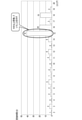
- FIG. 5 is a diagram showing another example of the screen in which the total value of the close contact time is displayed for each area.
- FIG. 6 is a diagram showing an example of a screen displayed for each area by distinguishing the breakdown of the total value of the close time for each worker.
- FIG. 1 is a block diagram showing an example of an electronic circuit configuration of a determination device to which the determination method of the embodiment of the present invention is applied.
- FIG. 2 is a conceptual diagram showing an example of a
- FIG. 7 is a diagram showing another example of the screen displayed for each area by distinguishing the breakdown of the total value of the close time for each worker.
- FIG. 8 is a table showing an example of a screen in which the breakdown of the total value of the close time shown in FIGS. 6 and 7 is displayed separately for each worker and for each time zone.
- FIG. 9 is a table showing an example of a screen in which each worker determined to be in close contact with each area is clearly shown with close time.
- FIG. 10 is a table showing an example of a screen in which each worker determined to be in close contact is clearly shown with time.
- FIG. 11 is a diagram showing an example of a screen in which the change history of the number of people determined to be close to each other in a certain area is clearly shown.
- FIG. 12 is a flowchart showing an operation example of the determination device to which the determination method of the embodiment of the present invention is applied.
- FIG. 1 is a block diagram showing an example of an electronic circuit configuration of a determination device to which the determination method of the embodiment of the present invention is applied.
- the determination device 10 is a device that determines the congestion or closeness of people in the monitored area.
- the monitored area is a factory and a person is a worker of the factory will be described, although not limited.
- the memory 20 stores a processing module 21, a stay information acquisition module 22, a density determination module 23, a close determination module 24, and a display control module 25 as a program for realizing the determination device 10.
- These program modules 21 to 25 may be stored in the memory 20 in advance, or may be read and stored in the memory 20 from an external recording medium 13 such as a memory card via the recording medium reading unit 14. You may. These program modules 21 to 25 cannot be rewritten.
- a writable data area 29 is secured as a memory area for storing rewritable data.
- the CPU 12 is an example of one or a plurality of processors capable of executing each program module 21 to 25, and controls the operation of each part of the circuit according to each program module 21 to 25.
- FIG. 2 is a conceptual diagram showing an example of the connection relationship between the determination device and other devices.
- a position sensor 110 to which a unique sensor ID is assigned is attached to each worker 100.
- the position sensor 110 measures the position of the worker 100 via the GPS function, the WiFi function, or the beacon 125, and transmits the measured position information together with the sensor ID to the determination device 10 via the communication network 70.
- each worker 100 may be equipped with a video sensor 115 such as a camera instead of the position sensor 110 as described above or in addition to the position sensor 110.
- the image sensor 115 is also given a unique sensor ID.
- the video sensor 115 captures an image on the line of sight of each worker 100, and transmits the captured image information together with the sensor ID to the determination device 10 via the communication network 70.
- the storage device 30 includes a worker database 31, a location information database 32, and a dense close determination information database.
- the worker database 31 stores the worker ID (for example, employee number, etc.) of each worker 100. Further, the sensor IDs of the position sensor 110 and the image sensor 115 attached to each worker 100 are also stored in association with the worker ID of the corresponding worker 100.
- the location information database 32 is a database for storing the location information of each worker 100 in the factory in association with the worker ID of the worker 100 together with the time information.
- the denseness close determination information database is a database for storing information related to the determination result by the denseness determination module 23 and the closeness determination module 24.
- the storage device 30 for storing these databases 31 to 33 is, for example, an SSD (Solid State Drive), an HDD (Hard Disk Drive), or the like.
- the communication unit 15 is connected to the communication network 70, and receives and receives the position information transmitted from the position sensor 110 and the video information transmitted from the video sensor 115 together with the sensor ID via the communication network 70.
- the generated position information or video information is output to the processing module 21 together with the sensor ID.
- the position information (and / or the video information) from the position sensor 110 (and / or the video sensor 115) is transmitted by the communication unit 15 realized by the gateway via the communication network 70.
- An example of being received is shown.
- the communication unit 15 In order to display the monitoring result or the like displayed from the display unit 16 by the display control module 25 from the external terminal 130, the communication unit 15 also displays the data necessary for displaying the monitoring result or the like as shown in FIG. It can also be output to the external terminal 130 via the communication network 70.
- the processing module 21 acquires the worker ID associated with the sensor ID from the worker database 31, and obtains the worker ID as the position information and the sensor ID. At the same time, it is output to the location information database 32.
- the processing module 21 acquires the worker ID associated with the sensor ID from the worker database 31 and also positions the position from the video information. Information is acquired, for example, by AI. Then, similarly, the worker ID is output to the position information database 32 together with the position information and the sensor ID.
- the position information database 32 stores the position information output from the processing module 21 in association with the time information, the worker ID, and the sensor ID.
- the position information can be expressed in the form of coordinates obtained by a method such as three-point positioning using a Bluetooth (registered trademark) beacon, for example.
- the position information database 32 has, as time information, time information timed by the internal clock (not shown) of the determination device 10 or time synchronized with the clock (timekeeping means) of the external system to which the determination device 10 is connected. Information can be used.
- the stay information acquisition module 22 stayed with the stayed worker 100 in each area in the factory based on the position information and the time information stored in association with the worker ID from the position information database 32.
- the time zone in which the worker stayed is acquired for each 100 workers.
- the congestion determination module 23 covers an area where a plurality of people have stayed for a predetermined continuous time length (for example, 15 minutes) or more, and an area with a large congestion. (Hereinafter, also referred to as "dense area").
- the closeness determination module 24 is close to the position information database 32 within a predetermined proximity distance (for example, 1 m) for each area based on the position information and the time information stored in association with the worker ID. It is determined that the plurality of workers 100 staying and the time zone in which each of these workers 100 stays continuously within a short distance.
- a predetermined proximity distance for example, 1 m
- the closeness determination module 24 further brings these workers 100 into close contact with each other when the time length corresponding to the determined time zone is a predetermined continuous time length (for example, 15 minutes) or more. Is determined.
- the close contact determination module 24 calculates the proximity distance between the plurality of workers 100 who stayed in each area at the same time at the same time based on the position information and the time information stored in the position information database 32. do.
- the proximity distance between two workers can be calculated using, for example, a trigonometric function.
- FIG. 3 is an example showing a method of calculating the close distance between two workers using a trigonometric function.
- a wristwatch-type position sensor 110 is attached to the worker 100A and the worker 100C.
- (x 1 , y 1 ) is stored as the position information of the position A of the worker 100A at a certain time
- (x 2 , y 2 ) is stored as the position information of the position C of the worker 100C. Has been done.
- the close contact determination module 24 calculates the distance between the position A of the worker 100A and the position C of the worker 100C from the following formula. ((X 2- x 1 ) 2 + (y 2- y 1 ) 2 ) (1/2)
- the heights of the workers 100A and 100C are about the same, and they are handled in two dimensions consisting of x and y coordinates.
- x, y, z It can be dealt with by extending it to three dimensions consisting of coordinates and handling it in the same mathematical manner. Further, since the distance between the position A and the position C is short, calibration considering the arc of the earth is unnecessary.
- the closeness determination module 24 can calculate the distance between workers at the same time as described above, for example, the closeness determination module 24 is close to each other within 1 m continuously for 15 minutes or more, that is, the worker 100 satisfying the close contact condition. (For example, worker 100A and worker 100C) can be determined.
- the closeness determination module 24 includes the worker IDs of the workers 100 (for example, the worker 100A and the worker 100C) determined to satisfy the close condition for each area, and the worker 100 (for example, the worker 100A). And the time information and the position information corresponding to the time zone and the position where the worker 100C) was determined to stay continuously within the close distance are associated with each other and stored in the dense close determination information database.
- each worker 100 determined to satisfy the close contact condition for each area A screen on which the total value of the lengths of consecutive stays within a short distance is clearly displayed is displayed from the display screen of the external terminal 130 via the display unit 16 or the communication network 70. 4 and 5 show an example thereof.
- FIG. 4 is a plan view showing the layout in the factory, showing an example of a screen in which the total value of the close contact time is displayed for each area.
- the area where the total value of the close contact time is zero or more is shown by hatching.
- the total value is displayed as a number in "minute" units.
- the area indicated by double-sided hatching is an area belonging to a group having a large total value when the total value is divided into two groups, and the area indicated by one-sided hatching is an area belonging to a group having a small total value. ..
- "15" shown in a circle is an area ID for identifying an area.
- FIG. 5 is a diagram showing another example of the screen in which the total value of the close contact time is displayed for each area.
- the horizontal axis indicates the area
- the vertical axis indicates the close time (minutes).
- the close contact time is 42 (minutes) in total, and it can be seen that the close contact time is continuous for 15 minutes or more.
- the display control module 25 also displays the breakdown of the close time on the screen as illustrated in FIG. 5 from the display screen of the external terminal 130 via the display unit 16 or the communication network 70, distinguishing each worker. You can also do it. 6 and 7 show an example thereof.
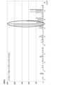
- FIG. 6 is a diagram showing an example of a screen displayed for each area by distinguishing the breakdown of the total value of the close time for each worker.
- FIG. 7 is a diagram showing another example of the screen displayed for each area by distinguishing the breakdown of the total value of the close time for each worker.
- the horizontal axis indicates the area, and the vertical axis indicates the close time (minutes).
- the display control module 25 further classifies the breakdown of the total value of the close time on the screen as illustrated in FIGS. 6 and 7 by time zone, and further distinguishes the breakdown by time zone, and further distinguishes the external terminal via the display unit 16 or the communication network 70. It can also be displayed from the display screen of 130.
- FIG. 8 shows an example thereof.
- FIG. 8 is a table showing an example of a screen in which the breakdown of the total value of the close time shown in FIGS. 6 and 7 is displayed separately for each worker and for each time zone.
- the vertical axis shows the area
- the horizontal axis shows the time zone in the first row
- the worker in the second row
- the numerical value shown in FIG. 8 is the close time in minutes for each worker, which is displayed separately for each area and each time zone.
- the table format as shown in FIG. 8 is only an example, and is a graph. It may be displayed in a format.
- each worker 100 determined to stay in close proximity to each other within a close distance for each area based on the information stored in the dense close determination information database is closely determined over time.
- the specified screen can be displayed from the display screen of the external terminal 130 via the display unit 16 or the communication network 70.
- FIG. 9 shows an example thereof.
- FIG. 9 is a table showing an example of a screen in which each worker 100 determined to be staying closely in each area is clearly shown with a close time.
- the vertical axis shows the close time (minutes), and the horizontal axis shows the area in the first row and the worker in the second row.
- the numerical value "1" shown in FIG. 9 indicates the worker 100 who stayed for the time shown on the vertical axis in the area shown on the horizontal axis.
- the table format as shown in FIG. 9 is used for each area.
- the above is just an example, and may be displayed in a graph format.
- the display control module 25 displays a screen as shown in FIG. 9 and a simplified screen as shown in FIG. 10 from the display screen of the external terminal 130 via the display unit 16 or the communication network 70. You can also. An example thereof is shown in FIG.
- FIG. 10 is a table showing an example of a screen in which each worker 100 determined to be in close contact is clearly shown together with the close time length.
- the vertical axis shows the close time (minutes), and the horizontal axis shows the worker.
- the numerical value "1" shown in FIG. 10 indicates the worker 100 who has stayed for a close time shown on the vertical axis, and FIG. 10 ignores the area of the first stage on the horizontal axis in FIG. , It is displayed by putting it together only in the worker's display.
- the display control module 25 can further display a screen in which the change history of the number of people determined to be in close contact is clearly shown for each area based on the information stored in the dense closeness determination information database. .. An example thereof is shown in FIG.
- FIG. 11 is a diagram showing an example of a screen in which the change history of the number of people determined to be close to each other in a certain area is clearly shown.
- the horizontal axis shows time and the vertical axis shows the number of people staying.
- the solid line shows the change in the number of people determined to be in close contact.
- the number of solid lines displayed is large, and the time zone displayed in dark indicates that the closely related partner has changed frequently. Then, it is shown that the number of closely related partners increases as the height increases in the vertical direction. Therefore, it can be seen that the display higher in the vertical direction indicates that many workers are in close contact with each other, and that the larger the area displayed darker, the more frequently the workers come and go. That is, it is possible to visually indicate the time zone and degree of close contact.
- the area selection button EA is also displayed in FIG. 11, and the user can switch to the display of the change history for that area by designating a desired area from the area selection button EA.
- the display control module 25 displays a screen as illustrated in FIGS. 4 to 11 based on the information stored in the dense close determination information database. It is possible.
- FIG. 12 is a flowchart showing an operation example of the determination device to which the determination method of the embodiment of the present invention is applied.
- a position sensor 110 to which a unique sensor ID is assigned is attached to each worker 100. Further, each worker 100 may be equipped with a video sensor 115 such as a camera instead of the position sensor 110 or in addition to the position sensor 110.
- the position information of the worker 100 (sensing information by the position sensor 110) measured by the position sensor 110 is transmitted from the position sensor 110 to the determination device 10 together with the sensor ID.
- the video information captured by the video sensor 115 (sensing information by the video sensor 115) is also transmitted from the video sensor 115 to the determination device 10 via the communication network 70 together with the sensor ID (S1).
- the position information and sensor ID which is the sensing information transmitted from the position sensor 110
- the video information and the sensor ID which are the sensing information transmitted from the video sensor 115
- the worker ID associated with the sensor ID is acquired from the worker database 31.
- the worker ID associated with the sensor ID is acquired from the worker database 31 (S2).
- the worker ID acquired in step S2 is the position information together with the position information and the sensor ID. It is output to the database 32, and the location information is associated with the time information, the worker ID, and the sensor ID and stored in the location information database 32 (S5).
- the sensing information transmitted in step S1 is video information (S3: No)
- position information is acquired from the video information by, for example, AI (S4).
- the worker ID acquired in step S2 is output to the position information database 32 together with the position information and the sensor ID acquired in step S4, and the position information is associated with the time information, the worker ID, and the sensor ID. And stored in the location information database 32 (S5).
- the stay information acquisition module 22 the worker 100 who stayed in each area in the factory based on the position information and the time information stored in association with the worker ID from the position information database 32. , The time zone in which the worker stayed is acquired for each 100 workers who stayed (S6).
- the area where a plurality of people have stayed for a predetermined continuous time length (for example, 15 minutes) or more is crowded by the congestion determination module 23. It is determined to be an area (S7).
- the close contact determination module 24 makes each area within a predetermined proximity distance (for example, 1 m). Workers 100 (for example, the worker 100A and the worker 100C shown in FIG. 3) and each of these workers 100 (for example, the worker 100A and the worker 100C shown in FIG. 3) staying close to each other It is determined that the time zone has been continuously stayed (S8).
- a predetermined proximity distance for example, 1 m. Workers 100 (for example, the worker 100A and the worker 100C shown in FIG. 3) and each of these workers 100 (for example, the worker 100A and the worker 100C shown in FIG. 3) staying close to each other It is determined that the time zone has been continuously stayed (S8).
- the closeness determination module 24 when the time length corresponding to the determined time zone is a predetermined continuous time length (for example, 15 minutes) or more, they stay close to each other within a close distance.
- Each worker 100 for example, the worker 100A and the worker 100C shown in FIG. 3 is determined to be in close contact with each other (S9).
- the proximity distance to each other at the same time is determined based on the position information and the time information stored in the position information database 32. For example, it is calculated using a trigonometric function.
- the worker IDs of the workers 100 (for example, the worker 100A and the worker 100C) determined to satisfy the close condition are determined for each area, and each of these workers 100 (for example, the worker 100C).
- the time information and the position information corresponding to the time zone and the position where the worker 100A and the worker 100C are continuously stayed within the close distance are associated with each other and stored in the dense close judgment information database (the worker 100A and the worker 100C). S10).
- the display control module 25 creates a screen as illustrated in FIGS. 4 to 11, for example, the display unit 16 or the communication network 70. It is displayed from the display screen of the external terminal 130 via (S11).
- the determination device to which the determination method of the embodiment of the present invention is applied As described above, according to the determination device to which the determination method of the embodiment of the present invention is applied, the crowdedness and close contact state of workers and the like in each area in the monitored area such as a factory can be seen from various viewpoints. It becomes possible to grasp.
Abstract
Provided are a determination device, a determination method, and a program for determining the crowdedness of people, such as workers, in each area within a region to be monitored, such as a factory. According to an embodiment, a determination device for determining the crowdedness of people in each area within a region to be monitored comprises: a first database that stores location information indicating the location of each person in the region to be monitored, and time information in association with corresponding personal identification information; a stay information acquisition unit that acquires a person who stayed in each area and a staying time band of each person who stayed, from the location information and the time information stored in association with the personal identification information in the first database; and a first determination unit that determines, on the basis of a result acquired by the stay information acquisition unit, that an area in which a plurality of people stayed for a predetermined continuous time length or more is a highly crowded area.
Description
本発明の実施形態は、工場等の監視対象領域内の各エリアにおける、作業者等の人の密集を判定する判定装置、判定方法、およびプログラムに関する。
An embodiment of the present invention relates to a determination device, a determination method, and a program for determining the density of workers and the like in each area in a monitored area such as a factory.
工場のように敷地面積が限られた施設において、高い生産効率を実現するために、レイアウトや動線の最適化が不可欠である。
In a facility with a limited site area such as a factory, it is essential to optimize the layout and flow lines in order to achieve high production efficiency.
不適切なレイアウトは、効率的な作業の実現を阻害する要因となる。また、不適切な動線は、作業員の不必要な密集や密接をもたらし、作業効率の低下をもたらす恐れもある。
Inappropriate layout is a factor that hinders the realization of efficient work. In addition, improper flow lines may lead to unnecessary crowding and close contact of workers, resulting in a decrease in work efficiency.
さらには、作業員の不必要な密集や密接は、新型コロナウィルス等の感染防止の観点からも、望ましくない。
Furthermore, unnecessary crowding and close contact of workers is not desirable from the viewpoint of preventing infection with the new coronavirus.
本発明が解決しようとする課題は、工場等の監視対象領域内の各エリアにおける、作業者等の人の密集を判定する判定装置、判定方法、およびプログラムを提供することである。
An object to be solved by the present invention is to provide a determination device, a determination method, and a program for determining the density of people such as workers in each area in a monitored area such as a factory.
実施形態の判定装置は、監視対象領域内の各エリアにおける人の密集を判定する判定装置であって、第1のデータベースと、滞在情報取得部と、第1の判定部とを備えている。第1のデータベースは、前記監視対象領域内の各人の位置を表す位置情報を、時間情報とともに、対応する人の識別情報に関連付けて記憶する。滞在情報取得部は、前記第1のデータベースに、前記人の識別情報に関連付けて記憶された位置情報および時間情報から、前記各エリア毎に、滞在した人と、前記滞在した人毎の、滞在した時間帯とを取得する。第1の判定部は、前記滞在情報取得部によって取得された結果に基づいて、予め定めた連続時間長さ以上、複数の人が滞在していたエリアを、密集が多いエリアであると判定する。
The determination device of the embodiment is a determination device for determining the congestion of people in each area in the monitored area, and includes a first database, a stay information acquisition unit, and a first determination unit. The first database stores the position information representing the position of each person in the monitored area in association with the identification information of the corresponding person together with the time information. The stay information acquisition unit stays in each of the areas from the location information and the time information stored in the first database in association with the identification information of the person, for each person who stayed and for each person who stayed. And get the time zone. Based on the result acquired by the stay information acquisition unit, the first determination unit determines that the area where a plurality of people have stayed for a predetermined continuous time length or more is an area with a large density. ..
以下に、本発明の実施形態を、図面を参照して説明する。
Hereinafter, embodiments of the present invention will be described with reference to the drawings.
本発明の実施形態の判定方法が適用された判定装置について説明する。
The determination device to which the determination method of the embodiment of the present invention is applied will be described.
図1は、本発明の実施形態の判定方法が適用された判定装置の電子回路構成例を示すブロック図である。
FIG. 1 is a block diagram showing an example of an electronic circuit configuration of a determination device to which the determination method of the embodiment of the present invention is applied.
判定装置10は、監視対象領域内における人の密集や密接を判定する装置である。
The determination device 10 is a device that determines the congestion or closeness of people in the monitored area.
本発明の実施形態では、限定される訳ではないが、監視対象領域が工場であり、人が工場の作業員である例を説明する。
In the embodiment of the present invention, an example in which the monitored area is a factory and a person is a worker of the factory will be described, although not limited.
判定装置10の電子回路は、図1に示すように、バス11によって互いに接続されたCPU12、記録媒体読取部14、通信部15、表示部16(例えば、ディスプレイ)、メモリ20、および記憶装置30を備えている。
As shown in FIG. 1, the electronic circuit of the determination device 10 includes a CPU 12, a recording medium reading unit 14, a communication unit 15, a display unit 16 (for example, a display), a memory 20, and a storage device 30 connected to each other by a bus 11. It is equipped with.
メモリ20は、判定装置10を実現するプログラムとして、処理モジュール21、滞在情報取得モジュール22、密集判定モジュール23、密接判定モジュール24、および表示制御モジュール25を記憶している。
The memory 20 stores a processing module 21, a stay information acquisition module 22, a density determination module 23, a close determination module 24, and a display control module 25 as a program for realizing the determination device 10.
これらプログラムモジュール21~25は、メモリ20に予め記憶されていてもよいし、あるいはメモリカード等の外部記録媒体13から記録媒体読取部14を介してメモリ20に読み込まれて記憶されたものであってもよい。これらプログラムモジュール21~25は、書き換えできないようになっている。
These program modules 21 to 25 may be stored in the memory 20 in advance, or may be read and stored in the memory 20 from an external recording medium 13 such as a memory card via the recording medium reading unit 14. You may. These program modules 21 to 25 cannot be rewritten.
メモリ20には、このようなユーザ書き換え不可能なメモリエリアの他に、書き換え可能なデータを記憶するメモリエリアとして、書込可能データエリア29が確保されている。
In the memory 20, in addition to such a memory area that cannot be rewritten by the user, a writable data area 29 is secured as a memory area for storing rewritable data.
CPU12は、各プログラムモジュール21~25を実行可能な1つまたは複数のプロセッサの一例であって、各プログラムモジュール21~25に従い回路各部の動作を制御する。
The CPU 12 is an example of one or a plurality of processors capable of executing each program module 21 to 25, and controls the operation of each part of the circuit according to each program module 21 to 25.
図2は、判定装置の他の装置との接続関係の一例を示す概念図である。
FIG. 2 is a conceptual diagram showing an example of the connection relationship between the determination device and other devices.
各作業者100には、固有のセンサIDが付与された位置センサ110が取り付けられている。
A position sensor 110 to which a unique sensor ID is assigned is attached to each worker 100.
位置センサ110は、GPS機能やWiFi機能、あるいはビーコン125を介して、作業者100の位置を測定し、測定した位置情報を、センサIDとともに、通信ネットワーク70を介して判定装置10に送信する。
The position sensor 110 measures the position of the worker 100 via the GPS function, the WiFi function, or the beacon 125, and transmits the measured position information together with the sensor ID to the determination device 10 via the communication network 70.
また、各作業者100には、上記のような位置センサ110の代わりに、あるいは位置センサ110に加えて、カメラ等の映像センサ115が取り付けられていてもよい。映像センサ115にも同様に、固有のセンサIDが付与されている。
Further, each worker 100 may be equipped with a video sensor 115 such as a camera instead of the position sensor 110 as described above or in addition to the position sensor 110. Similarly, the image sensor 115 is also given a unique sensor ID.
映像センサ115は、各作業者100の視線上の映像を撮像し、撮像した映像情報を、センサIDとともに、通信ネットワーク70を介して判定装置10に送信する。
The video sensor 115 captures an image on the line of sight of each worker 100, and transmits the captured image information together with the sensor ID to the determination device 10 via the communication network 70.
記憶装置30は、作業者データベース31、位置情報データベース32、および密集密接判定情報データベースを備えている。
The storage device 30 includes a worker database 31, a location information database 32, and a dense close determination information database.
作業者データベース31は、各作業者100の作業者ID(例えば、社員番号等)を記憶している。また、各作業者100に取り付けられている位置センサ110や映像センサ115のセンサIDも、対応する作業者100の作業者IDに関連付けて記憶している。
The worker database 31 stores the worker ID (for example, employee number, etc.) of each worker 100. Further, the sensor IDs of the position sensor 110 and the image sensor 115 attached to each worker 100 are also stored in association with the worker ID of the corresponding worker 100.
位置情報データベース32は、工場内の各作業者100の位置情報を、時間情報とともに、作業者100の作業者IDに関連付けて記憶するためのデータベースである。
The location information database 32 is a database for storing the location information of each worker 100 in the factory in association with the worker ID of the worker 100 together with the time information.
密集密接判定情報データベースは、密集判定モジュール23および密接判定モジュール24による判定結果に関連する情報を記憶するためのデータベースである。
The denseness close determination information database is a database for storing information related to the determination result by the denseness determination module 23 and the closeness determination module 24.
これらデータベース31~33を記憶する記憶装置30は、例えばSSD(Solid State Drive)やHDD(Hard Disk Drive)等からなる。
The storage device 30 for storing these databases 31 to 33 is, for example, an SSD (Solid State Drive), an HDD (Hard Disk Drive), or the like.
通信部15は、通信ネットワーク70に接続されており、通信ネットワーク70を介して、位置センサ110から送信される位置情報や、映像センサ115から送信される映像情報を、センサIDとともに受信し、受信した位置情報あるいは映像情報を、センサIDとともに処理モジュール21へ出力する。
The communication unit 15 is connected to the communication network 70, and receives and receives the position information transmitted from the position sensor 110 and the video information transmitted from the video sensor 115 together with the sensor ID via the communication network 70. The generated position information or video information is output to the processing module 21 together with the sensor ID.
図2では、一例として、位置センサ110(および/または、映像センサ115)からの位置情報(および/または、映像情報)が、通信ネットワーク70を経由して、ゲートウェイによって実現される通信部15によって受信される例が示されている。
In FIG. 2, as an example, the position information (and / or the video information) from the position sensor 110 (and / or the video sensor 115) is transmitted by the communication unit 15 realized by the gateway via the communication network 70. An example of being received is shown.
通信部15はまた、表示制御モジュール25によって表示部16から表示される監視結果等を、外部端末130から表示させるために、監視結果等の表示に必要なデータを、図2に示すように、通信ネットワーク70を介して外部端末130へ出力することもできる。
In order to display the monitoring result or the like displayed from the display unit 16 by the display control module 25 from the external terminal 130, the communication unit 15 also displays the data necessary for displaying the monitoring result or the like as shown in FIG. It can also be output to the external terminal 130 via the communication network 70.
処理モジュール21は、通信部15から位置情報およびセンサIDが出力されると、作業者データベース31から、センサIDに関連付けられている作業者IDを取得し、作業者IDを、位置情報およびセンサIDとともに、位置情報データベース32へ出力する。
When the position information and the sensor ID are output from the communication unit 15, the processing module 21 acquires the worker ID associated with the sensor ID from the worker database 31, and obtains the worker ID as the position information and the sensor ID. At the same time, it is output to the location information database 32.
また、処理モジュール21は、通信部15から映像情報およびセンサIDが出力されると、作業者データベース31から、センサIDに関連付けられている作業者IDを取得することに加えて、映像情報から位置情報を、例えばAIにより取得する。そして、同様に、作業者IDを、位置情報およびセンサIDとともに、位置情報データベース32へ出力する。
Further, when the video information and the sensor ID are output from the communication unit 15, the processing module 21 acquires the worker ID associated with the sensor ID from the worker database 31 and also positions the position from the video information. Information is acquired, for example, by AI. Then, similarly, the worker ID is output to the position information database 32 together with the position information and the sensor ID.
位置情報データベース32は、処理モジュール21から出力された位置情報を、時間情報、作業者ID、およびセンサIDに関連付けて記憶する。位置情報は、例えば、Bluetooth(登録商標)ビーコンを用いた三点測位などの手法で求められる座標の形式で表すことができる。位置情報データベース32は、時間情報として、判定装置10の内部時計(図示せず)によって計時された時間情報や、判定装置10が接続している外部システムの時計(計時手段)と同期された時間情報を使うことができる。
The position information database 32 stores the position information output from the processing module 21 in association with the time information, the worker ID, and the sensor ID. The position information can be expressed in the form of coordinates obtained by a method such as three-point positioning using a Bluetooth (registered trademark) beacon, for example. The position information database 32 has, as time information, time information timed by the internal clock (not shown) of the determination device 10 or time synchronized with the clock (timekeeping means) of the external system to which the determination device 10 is connected. Information can be used.
滞在情報取得モジュール22は、位置情報データベース32から、作業者IDに関連付けられて記憶された位置情報、および時間情報に基づいて、工場内の各エリア毎に、滞在した作業者100と、滞在した作業者100毎の、滞在した時間帯とを取得する。
The stay information acquisition module 22 stayed with the stayed worker 100 in each area in the factory based on the position information and the time information stored in association with the worker ID from the position information database 32. The time zone in which the worker stayed is acquired for each 100 workers.
密集判定モジュール23は、滞在情報取得モジュール22によって取得された結果に基づいて、予め定めた連続時間長さ(例えば、15分)以上、複数の人が滞在していたエリアを、密集が多いエリア(以下、「密集エリア」とも称する)であると判定する。
Based on the result acquired by the stay information acquisition module 22, the congestion determination module 23 covers an area where a plurality of people have stayed for a predetermined continuous time length (for example, 15 minutes) or more, and an area with a large congestion. (Hereinafter, also referred to as "dense area").
密接判定モジュール24は、位置情報データベース32に、作業者IDに関連付けて記憶された位置情報および時間情報に基づいて、各エリア毎に、予め定めた近接距離(例えば、1m)以内に近接して滞在している複数の作業者100と、これら各作業者100が、近接距離以内に、連続して滞在した時間帯とを判定する。
The closeness determination module 24 is close to the position information database 32 within a predetermined proximity distance (for example, 1 m) for each area based on the position information and the time information stored in association with the worker ID. It is determined that the plurality of workers 100 staying and the time zone in which each of these workers 100 stays continuously within a short distance.
密接判定モジュール24はさらに、判定された時間帯に対応する時間長さが、予め定めた連続時間長さ(例えば、15分)以上である場合、これら各作業者100を、互いに密接していると判定する。
The closeness determination module 24 further brings these workers 100 into close contact with each other when the time length corresponding to the determined time zone is a predetermined continuous time length (for example, 15 minutes) or more. Is determined.
このため、密接判定モジュール24は、各エリアに同時に滞在していた複数の作業者100について、位置情報データベース32に記憶された位置情報および時間情報に基づいて、同一時間における互いの近接距離を算出する。
Therefore, the close contact determination module 24 calculates the proximity distance between the plurality of workers 100 who stayed in each area at the same time at the same time based on the position information and the time information stored in the position information database 32. do.
2人の作業者間の近接距離は、例えば三角関数を用いて算出することができる。
The proximity distance between two workers can be calculated using, for example, a trigonometric function.
図3は、2人の作業者間の近接距離を、三角関数を用いて算出する方法を示す例である。
FIG. 3 is an example showing a method of calculating the close distance between two workers using a trigonometric function.
作業者100Aおよび作業者100Cには、腕時計タイプの位置センサ110が装着されている。
A wristwatch-type position sensor 110 is attached to the worker 100A and the worker 100C.
位置情報データベース32には、ある時間における作業者100Aの位置Aの位置情報として(x1、y1)が記憶され、作業者100Cの位置Cの位置情報として(x2、y2)が記憶されている。
In the position information database 32, (x 1 , y 1 ) is stored as the position information of the position A of the worker 100A at a certain time , and (x 2 , y 2 ) is stored as the position information of the position C of the worker 100C. Has been done.
このような場合、密接判定モジュール24は、作業者100Aの位置Aと、作業者100Cの位置Cとの間の距離を、以下の式から算出する。
((x2-x1)2+(y2-y1)2)(1/2)
なお、上記式では、作業者100A、100Cの身長は同程度であると仮定して、x、y座標からなる2次元で取り扱っているが、3次元を考慮した場合は、x、y、z座標からなる3次元に拡張し、同様の数学的取扱をすることによって対応可能である。また、位置Aと位置Cとの間の距離は近いことから、地球の弧を考慮した較正は不要である。 In such a case, the closecontact determination module 24 calculates the distance between the position A of the worker 100A and the position C of the worker 100C from the following formula.
((X 2- x 1 ) 2 + (y 2- y 1 ) 2 ) (1/2)
In the above formula, it is assumed that the heights of the workers 100A and 100C are about the same, and they are handled in two dimensions consisting of x and y coordinates. However, when three dimensions are taken into consideration, x, y, z It can be dealt with by extending it to three dimensions consisting of coordinates and handling it in the same mathematical manner. Further, since the distance between the position A and the position C is short, calibration considering the arc of the earth is unnecessary.
((x2-x1)2+(y2-y1)2)(1/2)
なお、上記式では、作業者100A、100Cの身長は同程度であると仮定して、x、y座標からなる2次元で取り扱っているが、3次元を考慮した場合は、x、y、z座標からなる3次元に拡張し、同様の数学的取扱をすることによって対応可能である。また、位置Aと位置Cとの間の距離は近いことから、地球の弧を考慮した較正は不要である。 In such a case, the close
((X 2- x 1 ) 2 + (y 2- y 1 ) 2 ) (1/2)
In the above formula, it is assumed that the heights of the
密接判定モジュール24は、上記のようにして、同一時間における作業者間の距離を算出できるので、例えば15分以上連続して、1m以内に近接していた、すなわち、密接条件を満たす作業者100(例えば、作業者100Aと作業者100C)を判定することができる。
Since the closeness determination module 24 can calculate the distance between workers at the same time as described above, for example, the closeness determination module 24 is close to each other within 1 m continuously for 15 minutes or more, that is, the worker 100 satisfying the close contact condition. (For example, worker 100A and worker 100C) can be determined.
密接判定モジュール24は、各エリア毎に、密接条件を満たすと判定された各作業者100(例えば、作業者100Aと作業者100C)の作業者IDと、これら作業者100(例えば、作業者100Aと作業者100C)について判定された、近接距離以内に連続して滞在した時間帯および位置に対応する時間情報および位置情報とを関連付けて、密集密接判定情報データベースに記憶させる。
The closeness determination module 24 includes the worker IDs of the workers 100 (for example, the worker 100A and the worker 100C) determined to satisfy the close condition for each area, and the worker 100 (for example, the worker 100A). And the time information and the position information corresponding to the time zone and the position where the worker 100C) was determined to stay continuously within the close distance are associated with each other and stored in the dense close determination information database.
表示制御モジュール25は、密接判定情報データベース33に記憶された情報に基づいて、各エリアが表示された工場のマップ上に、エリア毎に、密接条件を満たすと判定された各作業者100が、近接距離以内に連続して滞在した時間長さの合計値が明示された画面を、表示部16、あるいは、通信ネットワーク70を介して外部端末130の表示画面から表示させる。図4および図5に、その一例を示す。
In the display control module 25, on the map of the factory where each area is displayed based on the information stored in the closeness determination information database 33, each worker 100 determined to satisfy the close contact condition for each area A screen on which the total value of the lengths of consecutive stays within a short distance is clearly displayed is displayed from the display screen of the external terminal 130 via the display unit 16 or the communication network 70. 4 and 5 show an example thereof.
図4は、密接時間の合計値が、エリア毎に表示された画面の一例を示す、工場内のレイアウトを示す平面図である。
FIG. 4 is a plan view showing the layout in the factory, showing an example of a screen in which the total value of the close contact time is displayed for each area.
図4では、密接時間の合計値がゼロ以上であるエリアは、ハッチングで示されている。また、ハッチングで示されているエリアには、合計値が「分」単位の数字で表示されている。特に、両側ハッチングで示されるエリアは、合計値を2つのグループに分割した場合、合計値が大きいグループに属するエリアであり、片側ハッチングで示されるエリアは、合計値が小さいグループに属するエリアである。なお、丸印内に示される「15」は、エリアを識別するエリアIDである。
In FIG. 4, the area where the total value of the close contact time is zero or more is shown by hatching. In addition, in the area indicated by hatching, the total value is displayed as a number in "minute" units. In particular, the area indicated by double-sided hatching is an area belonging to a group having a large total value when the total value is divided into two groups, and the area indicated by one-sided hatching is an area belonging to a group having a small total value. .. In addition, "15" shown in a circle is an area ID for identifying an area.
図5は、密接時間の合計値が、エリア毎に表示された画面の別の例を示す図である。
FIG. 5 is a diagram showing another example of the screen in which the total value of the close contact time is displayed for each area.
図5において、横軸はエリアを示し、縦軸は密接時間(分)を示す。例えば、図中丸印に示すように、エリア「15」では、密接時間が合計して42(分)となっており、密接時間が15分以上連続していることが分かる。
In FIG. 5, the horizontal axis indicates the area, and the vertical axis indicates the close time (minutes). For example, as shown by the circles in the figure, in the area "15", the close contact time is 42 (minutes) in total, and it can be seen that the close contact time is continuous for 15 minutes or more.
表示制御モジュール25はまた、図5に例示するような画面において、密接時間の内訳を、作業者別に区別して、表示部16、あるいは、通信ネットワーク70を介して外部端末130の表示画面から表示させることもできる。図6および図7に、その一例を示す。
The display control module 25 also displays the breakdown of the close time on the screen as illustrated in FIG. 5 from the display screen of the external terminal 130 via the display unit 16 or the communication network 70, distinguishing each worker. You can also do it. 6 and 7 show an example thereof.
図6は、密接時間の合計値の内訳を、作業者毎に区別して、エリア毎に表示された画面の例を示す図である。
FIG. 6 is a diagram showing an example of a screen displayed for each area by distinguishing the breakdown of the total value of the close time for each worker.
図7は、密接時間の合計値の内訳を、作業者毎に区別して、エリア毎に表示された画面の別の例を示す図である。
FIG. 7 is a diagram showing another example of the screen displayed for each area by distinguishing the breakdown of the total value of the close time for each worker.
図6および図7において、横軸はエリアを示し、縦軸は密接時間(分)を示す。
In FIGS. 6 and 7, the horizontal axis indicates the area, and the vertical axis indicates the close time (minutes).
表示制御モジュール25はさらに、図6および図7に例示するような画面において、密接時間の合計値の内訳をさらに、時間帯別に区別して、表示部16、あるいは、通信ネットワーク70を介して外部端末130の表示画面から表示させることもできる。図8に、その一例を示す。
The display control module 25 further classifies the breakdown of the total value of the close time on the screen as illustrated in FIGS. 6 and 7 by time zone, and further distinguishes the breakdown by time zone, and further distinguishes the external terminal via the display unit 16 or the communication network 70. It can also be displayed from the display screen of 130. FIG. 8 shows an example thereof.
図8は、図6および図7に示される密接時間の合計値の内訳を、作業者別に、かつ時間帯別に区別して表示する画面の一例を示すテーブルである。
FIG. 8 is a table showing an example of a screen in which the breakdown of the total value of the close time shown in FIGS. 6 and 7 is displayed separately for each worker and for each time zone.
図8において縦軸はエリアを示し、横軸は1段目に時間帯を、2段目に作業者を示している。
In FIG. 8, the vertical axis shows the area, the horizontal axis shows the time zone in the first row, and the worker in the second row.
図8内に示される数値は、エリア別および時間帯別に区別して表示された、各作業者の分単位での密接時間である。
The numerical value shown in FIG. 8 is the close time in minutes for each worker, which is displayed separately for each area and each time zone.
なお、図6および図7に示される密接時間の合計値の内訳を、作業者別に、かつ時間帯別に区別して表示する場合、図8のようにテーブル形式で示すのはあくまで一例であり、グラフ形式で表示してもよい。
When the breakdown of the total value of the close time shown in FIGS. 6 and 7 is displayed separately for each worker and for each time zone, the table format as shown in FIG. 8 is only an example, and is a graph. It may be displayed in a format.
表示制御モジュール25はさらに、密集密接判定情報データベースに記憶された情報に基づいて、エリア毎に、近接距離以内に互いに近接して滞在していると判定された各作業者100が、密接時間とともに明示された画面を、表示部16、あるいは、通信ネットワーク70を介して外部端末130の表示画面から表示させることもできる。図9に、その一例を示す。
Further, in the display control module 25, each worker 100 determined to stay in close proximity to each other within a close distance for each area based on the information stored in the dense close determination information database is closely determined over time. The specified screen can be displayed from the display screen of the external terminal 130 via the display unit 16 or the communication network 70. FIG. 9 shows an example thereof.
図9は、エリア毎に、密接して滞在していると判定された各作業者100を、密接時間とともに明示した画面の例を示すテーブルである。
FIG. 9 is a table showing an example of a screen in which each worker 100 determined to be staying closely in each area is clearly shown with a close time.
図9において縦軸は密接時間(分)を示し、横軸は1段目にエリアを、2段目に作業者を示している。
In FIG. 9, the vertical axis shows the close time (minutes), and the horizontal axis shows the area in the first row and the worker in the second row.
図9内に示される数値「1」は、横軸に示されるエリアにおいて、縦軸に示される時間滞在していた作業者100を示している。
The numerical value "1" shown in FIG. 9 indicates the worker 100 who stayed for the time shown on the vertical axis in the area shown on the horizontal axis.
なお、エリア毎に、近接距離以内に互いに近接して滞在している、すなわち、密接していると判定された各作業者100を、密接時間とともに明示する場合、図9に示すようなテーブル形式で示すのはあくまで一例であり、グラフ形式で表示してもよい。
In addition, in the case of clearly indicating each worker 100 who is staying close to each other within a close distance, that is, determined to be close to each other, together with the close time, the table format as shown in FIG. 9 is used for each area. The above is just an example, and may be displayed in a graph format.
さらに表示制御モジュール25は、図9に示すような画面を、図10のように簡略化したな画面を、表示部16、あるいは、通信ネットワーク70を介して外部端末130の表示画面から表示させることもできる。その一例を図10に示す。
Further, the display control module 25 displays a screen as shown in FIG. 9 and a simplified screen as shown in FIG. 10 from the display screen of the external terminal 130 via the display unit 16 or the communication network 70. You can also. An example thereof is shown in FIG.
図10は、密接していると判定された各作業者100を、密接時間長さとともに明示した画面の例を示すテーブルである。
FIG. 10 is a table showing an example of a screen in which each worker 100 determined to be in close contact is clearly shown together with the close time length.
図10において縦軸は密接時間(分)を示し、横軸は作業者を示している。
In FIG. 10, the vertical axis shows the close time (minutes), and the horizontal axis shows the worker.
図10内に示される数値「1」は、縦軸に示される密接時間滞在していた作業者100を示しており、図10は、図9における横軸の1段目のエリアを無視して、作業者の表示のみにまとめることによって表示される。
The numerical value "1" shown in FIG. 10 indicates the worker 100 who has stayed for a close time shown on the vertical axis, and FIG. 10 ignores the area of the first stage on the horizontal axis in FIG. , It is displayed by putting it together only in the worker's display.
表示制御モジュール25はさらに、密集密接判定情報データベースに記憶された情報に基づいて、エリア毎に、密接していると判定された人の数の変化履歴が明示された画面を表示させることもできる。その一例を図11に示す。
The display control module 25 can further display a screen in which the change history of the number of people determined to be in close contact is clearly shown for each area based on the information stored in the dense closeness determination information database. .. An example thereof is shown in FIG.
図11は、あるエリアにおいて、密接していると判定された人の数の変化履歴が明示された画面の一例を示す図である。
FIG. 11 is a diagram showing an example of a screen in which the change history of the number of people determined to be close to each other in a certain area is clearly shown.
図11において横軸は時間を示し、縦軸は滞在人数を示す。
In FIG. 11, the horizontal axis shows time and the vertical axis shows the number of people staying.
図11において、実線は、密接していると判定された人の数の変化を示す。図中丸印で示されるように、表示される実線の数が多いことによって、濃く表示される時間帯は、密接関係にある相手が頻繁に変化したことを示す。そして、縦軸方向に高くなるにしたがって、密接関係にある相手が増えていることを示す。したがって、縦軸方向により高く表示されることは、多くの作業者が密接していることを示し、濃く表示される面積が多いほど、作業者の出入りが頻繁であることが分かる。すなわち、密接が発生した時間帯および程度を視覚的に示すことができる。
In FIG. 11, the solid line shows the change in the number of people determined to be in close contact. As shown by the circles in the figure, the number of solid lines displayed is large, and the time zone displayed in dark indicates that the closely related partner has changed frequently. Then, it is shown that the number of closely related partners increases as the height increases in the vertical direction. Therefore, it can be seen that the display higher in the vertical direction indicates that many workers are in close contact with each other, and that the larger the area displayed darker, the more frequently the workers come and go. That is, it is possible to visually indicate the time zone and degree of close contact.
また、図11には、エリア選択ボタンEAも表示されており、ユーザは、エリア選択ボタンEAから所望のエリアを指定することにより、そのエリアについての変化履歴の表示に切り替えることもできる。
In addition, the area selection button EA is also displayed in FIG. 11, and the user can switch to the display of the change history for that area by designating a desired area from the area selection button EA.
密集密接判定情報データベースには、各エリア毎に、密接条件を満たすと判定された各作業者100の作業者IDと、これら各作業者100についての、密接して滞在していた時間帯および位置に対応する時間情報および位置情報が記憶されているので、表示制御モジュール25は、密集密接判定情報データベースに記憶された情報に基づいて、図4~図11に例示されるような画面を表示させることが可能である。
In the dense close judgment information database, the worker ID of each worker 100 determined to satisfy the close condition, and the time zone and position where each worker 100 was closely stayed are stored in each area. Since the time information and the position information corresponding to the above are stored, the display control module 25 displays a screen as illustrated in FIGS. 4 to 11 based on the information stored in the dense close determination information database. It is possible.
次に、以上のように構成した本発明の実施形態の判定方法が適用された判定装置の動作例について説明する。
Next, an operation example of the determination device to which the determination method of the embodiment of the present invention configured as described above is applied will be described.
図12は、本発明の実施形態の判定方法が適用された判定装置の動作例を示すフローチャートである。
FIG. 12 is a flowchart showing an operation example of the determination device to which the determination method of the embodiment of the present invention is applied.
各作業者100には、固有のセンサIDが付与された位置センサ110が取り付けられている。また、各作業者100には、位置センサ110の代わりに、あるいは、位置センサ110に加えて、カメラ等の映像センサ115が取り付けられていてもよい。
A position sensor 110 to which a unique sensor ID is assigned is attached to each worker 100. Further, each worker 100 may be equipped with a video sensor 115 such as a camera instead of the position sensor 110 or in addition to the position sensor 110.
位置センサ110によって測定された、作業者100の位置情報(位置センサ110によるセンシング情報)は、位置センサ110から、センサIDとともに判定装置10に送信される。映像センサ115によって撮像された映像情報(映像センサ115によるセンシング情報)もまた、映像センサ115から、センサIDとともに、通信ネットワーク70を介して判定装置10に送信される(S1)。
The position information of the worker 100 (sensing information by the position sensor 110) measured by the position sensor 110 is transmitted from the position sensor 110 to the determination device 10 together with the sensor ID. The video information captured by the video sensor 115 (sensing information by the video sensor 115) is also transmitted from the video sensor 115 to the determination device 10 via the communication network 70 together with the sensor ID (S1).
位置センサ110から送信されたセンシング情報である位置情報およびセンサID、映像センサ115から送信されたセンシング情報である映像情報およびセンサIDは、判定装置10において通信部15によって受信され、通信部15によって、処理モジュール21へ出力される。
The position information and sensor ID, which is the sensing information transmitted from the position sensor 110, and the video information and the sensor ID, which are the sensing information transmitted from the video sensor 115, are received by the communication unit 15 in the determination device 10 and are received by the communication unit 15. , Is output to the processing module 21.
処理モジュール21では、通信部15から位置情報およびセンサIDが出力されると、作業者データベース31から、センサIDに関連付けられている作業者IDが取得される。同様に、処理モジュール21では、通信部15から映像情報およびセンサIDが出力された場合も、作業者データベース31から、センサIDに関連付けられている作業者IDが取得される(S2)。
In the processing module 21, when the position information and the sensor ID are output from the communication unit 15, the worker ID associated with the sensor ID is acquired from the worker database 31. Similarly, in the processing module 21, when the video information and the sensor ID are output from the communication unit 15, the worker ID associated with the sensor ID is acquired from the worker database 31 (S2).
さらに、処理モジュール21では、ステップS1で送信されたセンシング情報が位置情報であった場合(S3:Yes)には、ステップS2で取得された作業者IDが、位置情報およびセンサIDとともに、位置情報データベース32へ出力され、位置情報が、時間情報、作業者ID、およびセンサIDに関連付けられて、位置情報データベース32に記憶される(S5)。
Further, in the processing module 21, when the sensing information transmitted in step S1 is position information (S3: Yes), the worker ID acquired in step S2 is the position information together with the position information and the sensor ID. It is output to the database 32, and the location information is associated with the time information, the worker ID, and the sensor ID and stored in the location information database 32 (S5).
一方、処理モジュール21では、ステップS1で送信されたセンシング情報が映像情報であった場合(S3:No)には、例えばAIによって、映像情報から位置情報が取得される(S4)。その後、ステップS2で取得された作業者IDが、ステップS4で取得された位置情報およびセンサIDとともに、位置情報データベース32へ出力され、位置情報が、時間情報、作業者ID、およびセンサIDに関連付けられて、位置情報データベース32に記憶される(S5)。
On the other hand, in the processing module 21, when the sensing information transmitted in step S1 is video information (S3: No), position information is acquired from the video information by, for example, AI (S4). After that, the worker ID acquired in step S2 is output to the position information database 32 together with the position information and the sensor ID acquired in step S4, and the position information is associated with the time information, the worker ID, and the sensor ID. And stored in the location information database 32 (S5).
次に、滞在情報取得モジュール22によって、位置情報データベース32から、作業者IDに関連付けられて記憶された位置情報、および時間情報に基づいて、工場内の各エリア毎に、滞在した作業者100と、滞在した作業者100毎の、滞在した時間帯とが取得される(S6)。
Next, by the stay information acquisition module 22, the worker 100 who stayed in each area in the factory based on the position information and the time information stored in association with the worker ID from the position information database 32. , The time zone in which the worker stayed is acquired for each 100 workers who stayed (S6).
次に、滞在情報取得モジュール22によって取得された結果に基づいて、密集判定モジュール23によって、予め定めた連続時間長さ(例えば、15分)以上、複数の人が滞在していたエリアが、密集エリアであると判定される(S7)。
Next, based on the result acquired by the stay information acquisition module 22, the area where a plurality of people have stayed for a predetermined continuous time length (for example, 15 minutes) or more is crowded by the congestion determination module 23. It is determined to be an area (S7).
次に、位置情報データベース32に、作業者IDに関連付けて記憶された位置情報および時間情報に基づいて、密接判定モジュール24によって、各エリア毎に、予め定めた近接距離(例えば、1m)以内に互いに近接して滞在している作業者100(例えば、図3に示す作業者100Aと作業者100C)と、これら各作業者100(例えば、図3に示す作業者100Aと作業者100C)が、連続して滞在した時間帯とが判定される(S8)。
Next, based on the position information and the time information stored in the position information database 32 in association with the worker ID, the close contact determination module 24 makes each area within a predetermined proximity distance (for example, 1 m). Workers 100 (for example, the worker 100A and the worker 100C shown in FIG. 3) and each of these workers 100 (for example, the worker 100A and the worker 100C shown in FIG. 3) staying close to each other It is determined that the time zone has been continuously stayed (S8).
密接判定モジュール24ではさらに、判定された時間帯に対応する時間長さが、予め定めた連続時間長さ(例えば、15分)以上である場合、近接距離以内に互いに近接して滞在している各作業者100(例えば、図3に示す作業者100Aと作業者100C)は、互いに密接していると判定される(S9)。
Further, in the closeness determination module 24, when the time length corresponding to the determined time zone is a predetermined continuous time length (for example, 15 minutes) or more, they stay close to each other within a close distance. Each worker 100 (for example, the worker 100A and the worker 100C shown in FIG. 3) is determined to be in close contact with each other (S9).
このため、密接判定モジュール24では、各エリアに同時に滞在していた複数の作業者100について、位置情報データベース32に記憶された位置情報および時間情報に基づいて、同一時間における互いの近接距離が、例えば三角関数を用いて算出される。
Therefore, in the close contact determination module 24, for a plurality of workers 100 who have stayed in each area at the same time, the proximity distance to each other at the same time is determined based on the position information and the time information stored in the position information database 32. For example, it is calculated using a trigonometric function.
その後、密接判定モジュール24では、各エリア毎に、密接条件を満たすと判定された各作業者100(例えば、作業者100Aと作業者100C)の作業者IDと、これら各作業者100(例えば、作業者100Aと作業者100C)について判定された、近接距離以内に連続して滞在した時間帯および位置に対応する時間情報および位置情報とが関連付けられて、密集密接判定情報データベースに記憶される(S10)。
After that, in the close contact determination module 24, the worker IDs of the workers 100 (for example, the worker 100A and the worker 100C) determined to satisfy the close condition are determined for each area, and each of these workers 100 (for example, the worker 100C). The time information and the position information corresponding to the time zone and the position where the worker 100A and the worker 100C are continuously stayed within the close distance are associated with each other and stored in the dense close judgment information database (the worker 100A and the worker 100C). S10).
このように、密集密接判定情報データベースに記憶された情報に基づいて、表示制御モジュール25によって、例えば図4~図11に例示されるような画面が作成され、表示部16、あるいは、通信ネットワーク70を介して外部端末130の表示画面から表示される(S11)。
In this way, based on the information stored in the dense close-up determination information database, the display control module 25 creates a screen as illustrated in FIGS. 4 to 11, for example, the display unit 16 or the communication network 70. It is displayed from the display screen of the external terminal 130 via (S11).
図4に例示されるような画面によれば、密接が発生したエリアを、視覚的に把握することが可能となる。
According to the screen as illustrated in FIG. 4, it is possible to visually grasp the area where the closeness has occurred.
図5に例示されるような画面によれば、密接が発生したエリアの密接度合いを、他のエリアと比較しながら把握することが可能となる。
According to the screen as illustrated in FIG. 5, it is possible to grasp the degree of closeness of the area where closeness has occurred while comparing it with other areas.
図6および図7に例示されるような画面によれば、どの作業者の密接度合が高いのかを個別に把握することが可能となる。
According to the screens as illustrated in FIGS. 6 and 7, it is possible to individually grasp which worker has a high degree of closeness.
図8に例示されるような画面によれば、どのエリアにおいて、どの時間帯に、どの作業者の密接度合が高いのかを詳細に把握することが可能となる。
According to the screen as illustrated in FIG. 8, it is possible to grasp in detail which worker has a high degree of closeness in which area and in which time zone.
図9に例示されるような画面によれば、どのエリアにおいて、どの作業者がどの作業者と、どの程度の密接状態にあったのかを把握することが可能となる。
According to the screen as illustrated in FIG. 9, it is possible to grasp which worker was in close contact with which worker in which area.
図10に例示されるような画面によれば、どの作業者がどの作業者と、どの程度の密接状態にあったのかを把握することが可能となる。
According to the screen as illustrated in FIG. 10, it is possible to grasp which worker was in close contact with which worker.
図11に例示されるような画面によれば、密接が発生した時間帯およびその程度を視覚的に把握することが可能となる。
According to the screen as illustrated in FIG. 11, it is possible to visually grasp the time zone and the degree of close contact.
このように、本発明の実施形態の判定方法が適用された判定装置によれば、工場等の監視対象領域内の各エリアにおける、作業者等の人の密集や密接の状態を様々な観点から把握することが可能となる。
As described above, according to the determination device to which the determination method of the embodiment of the present invention is applied, the crowdedness and close contact state of workers and the like in each area in the monitored area such as a factory can be seen from various viewpoints. It becomes possible to grasp.
本発明のいくつかの実施形態を説明したが、これらの実施形態は、例として提示したものであり、発明の範囲を限定することは意図していない。これら実施形態は、その他の様々な形態で実施されることが可能であり、発明の要旨を逸脱しない範囲で、種々の省略、置き換え、変更を行うことができる。これら実施形態やその変形は、発明の範囲や要旨に含まれると同様に、特許請求の範囲に記載された発明とその均等の範囲に含まれるものである。
Although some embodiments of the present invention have been described, these embodiments are presented as examples and are not intended to limit the scope of the invention. These embodiments can be implemented in various other embodiments, and various omissions, replacements, and changes can be made without departing from the gist of the invention. These embodiments and variations thereof are included in the scope of the invention described in the claims and the equivalent scope thereof, as are included in the scope and gist of the invention.
Although some embodiments of the present invention have been described, these embodiments are presented as examples and are not intended to limit the scope of the invention. These embodiments can be implemented in various other embodiments, and various omissions, replacements, and changes can be made without departing from the gist of the invention. These embodiments and variations thereof are included in the scope of the invention described in the claims and the equivalent scope thereof, as are included in the scope and gist of the invention.
Claims (12)
- 監視対象領域内の各エリアにおける人の密集を判定する判定装置であって、
前記監視対象領域内の各人の位置を表す位置情報を、時間情報とともに、対応する人の識別情報に関連付けて記憶する第1のデータベースと、
前記第1のデータベースに、前記人の識別情報に関連付けて記憶された位置情報および時間情報から、前記各エリア毎に、滞在した人と、前記滞在した人毎の、滞在した時間帯とを取得する滞在情報取得部と、
前記滞在情報取得部によって取得された結果に基づいて、予め定めた連続時間長さ以上、複数の人が滞在していたエリアを、密集が多いエリアであると判定する第1の判定部とを備えた、判定装置。 It is a judgment device that judges the congestion of people in each area in the monitored area.
A first database that stores position information indicating the position of each person in the monitored area in association with the identification information of the corresponding person together with time information.
From the location information and time information stored in association with the identification information of the person in the first database, the person who stayed in each area and the time zone in which the person stayed are acquired. Stay information acquisition department and
Based on the result acquired by the stay information acquisition unit, the first determination unit that determines that the area where a plurality of people have stayed for a predetermined continuous time length or more is an area with a large density. Judgment device equipped. - 前記各エリア毎に、予め定めた近接距離以内に互いに近接して滞在している人と、前記近接距離以内に互いに近接して滞在している各人が、前記近接距離以内に、連続して滞在した時間帯とを判定する第2の判定部をさらに備えた、請求項1に記載の判定装置。 In each of the areas, a person who stays close to each other within a predetermined close distance and a person who stays close to each other within the close distance continue to stay within the close distance. The determination device according to claim 1, further comprising a second determination unit for determining a staying time zone.
- 前記第2の判定部はさらに、前記時間帯に対応する時間長さが、前記予め定めた連続時間長さ以上である場合、前記近接距離以内に互いに近接して滞在している各人が、互いに密接していると判定する、請求項2に記載の判定装置。 Further, when the time length corresponding to the time zone is equal to or longer than the predetermined continuous time length, the second determination unit further indicates that each person staying in close proximity to each other within the close distance. The determination device according to claim 2, wherein it is determined that they are in close contact with each other.
- 前記各エリア毎に、前記第2の判定部によって、前記近接距離以内に互いに近接して滞在していると判定された各人の識別情報と、前記判定された各人について判定された、前記近接距離以内に連続して滞在した時間帯および位置に対応する時間情報および位置情報とを関連付けて記憶する第2のデータベースをさらに備えた、請求項2に記載の判定装置。 For each of the areas, the second determination unit has determined the identification information of each person who is determined to stay in close proximity to each other within the close distance, and the determination for each of the determined persons. The determination device according to claim 2, further comprising a second database for storing time information and position information corresponding to time zones and positions continuously stayed within a short distance.
- 前記第2のデータベースに記憶された情報に基づいて、前記エリア毎に、前記近接距離以内に互いに近接して滞在していると判定された各人が、前記近接距離以内に連続して滞在した時間長さの合計値が明示された画面を表示させる表示制御部をさらに備えた、請求項4に記載の判定装置。 Based on the information stored in the second database, each person determined to stay in close proximity to each other within the close distance in each of the areas stayed continuously within the close distance. The determination device according to claim 4, further comprising a display control unit for displaying a screen on which the total value of time lengths is clearly indicated.
- 前記表示制御部は、前記画面において、前記合計値の内訳を、人別に区別して表示させる、請求項5に記載の判定装置。 The determination device according to claim 5, wherein the display control unit displays the breakdown of the total value separately for each person on the screen.
- 前記表示制御部は、前記画面において、前記合計値の内訳をさらに、時間帯別に区別して表示させる、請求項6に記載の判定装置。 The determination device according to claim 6, wherein the display control unit further displays the breakdown of the total value on the screen separately for each time zone.
- 前記第2のデータベースに記憶された情報に基づいて、前記エリア毎に、前記近接距離以内に互いに近接して滞在していると判定された各人が、時間帯別に区別された画面を表示させる表示制御部をさらに備えた、請求項4に記載の判定装置。 Based on the information stored in the second database, each person who is determined to be staying in close proximity to each other within the close distance for each of the areas displays a screen distinguished by time zone. The determination device according to claim 4, further comprising a display control unit.
- 前記第2の判定部によって、密接が多いと判定されたエリアについて、前記近接距離以内に互いに近接して滞在していると判定された各人が、近接していた時間長さとともに明示された画面を表示させる表示制御部をさらに備えた、請求項2に記載の判定装置。 For the area determined to be close to each other by the second determination unit, each person determined to stay in close proximity to each other within the close distance is specified together with the length of time that they were in close proximity. The determination device according to claim 2, further comprising a display control unit for displaying a screen.
- 前記第2のデータベースに記憶された情報に基づいて、前記エリア毎に、前記近接距離以内に互いに近接して滞在していると判定された人の数の変化履歴が明示された画面を表示させる表示制御部をさらに備えた、請求項4に記載の判定装置。 Based on the information stored in the second database, a screen showing the change history of the number of people determined to be staying in close proximity to each other within the close distance is displayed for each of the areas. The determination device according to claim 4, further comprising a display control unit.
- 監視対象領域内の各エリアにおける人の密集を判定する判定装置によって実施される判定方法であって、
前記判定装置は、
前記監視対象領域内の各人の位置を表す位置情報を、時間情報とともに、対応する人の識別情報に関連付けて第1のデータベースに記憶し、
前記第1のデータベースに、前記人の識別情報に関連付けて記憶された位置情報および時間情報から、前記各エリア毎に、滞在した人と、前記滞在した人毎の、滞在した時間帯とを取得し、
前記取得された結果に基づいて、予め定めた連続時間長さ以上、複数の人が滞在していたエリアを、密集が多いエリアであると判定する、判定方法。 It is a judgment method implemented by a judgment device for judging the congestion of people in each area in the monitored area.
The determination device is
The position information indicating the position of each person in the monitored area is stored in the first database in association with the identification information of the corresponding person together with the time information.
From the location information and time information stored in association with the identification information of the person in the first database, the person who stayed in each area and the time zone in which the person stayed are acquired. death,
A determination method for determining an area in which a plurality of people have stayed for a predetermined continuous time length or more as an area with a large concentration based on the acquired results. - 監視対象領域内の各エリアにおける人の密集を判定するためのプログラムであって、 前記監視対象領域内の各人の位置を表す位置情報を、時間情報とともに、対応する人の識別情報に関連付けて第1のデータベースに記憶する機能、
前記第1のデータベースに、前記人の識別情報に関連付けて記憶された位置情報および時間情報から、前記各エリア毎に、滞在した人と、前記滞在した人毎の、滞在した時間帯とを取得する機能、
前記取得された結果に基づいて、予め定めた連続時間長さ以上、複数の人が滞在していたエリアを、密集が多いエリアであると判定する機能、をコンピュータに実現させるためのプログラム。
It is a program for determining the congestion of people in each area in the monitored area, and the position information indicating the position of each person in the monitored area is associated with the identification information of the corresponding person together with the time information. Function to store in the first database,
From the location information and time information stored in association with the identification information of the person in the first database, the person who stayed in each area and the time zone in which the person stayed are acquired. Function to do,
Based on the obtained results, a program for realizing a function of determining an area where a plurality of people have stayed for a predetermined continuous time length or more as an area with a lot of congestion.
Priority Applications (4)
| Application Number | Priority Date | Filing Date | Title |
|---|---|---|---|
| EP21842582.5A EP4184418A1 (en) | 2020-07-16 | 2021-07-01 | Determination device, determination method, and program |
| CN202180043204.1A CN115917579A (en) | 2020-07-16 | 2021-07-01 | Determination device, determination method, and program |
| KR1020227043653A KR20230011998A (en) | 2020-07-16 | 2021-07-01 | Judging apparatus, judging method and program |
| US18/151,636 US20230162506A1 (en) | 2020-07-16 | 2023-01-09 | Determination apparatus, determination method, and program |
Applications Claiming Priority (2)
| Application Number | Priority Date | Filing Date | Title |
|---|---|---|---|
| JP2020122362A JP7408502B2 (en) | 2020-07-16 | 2020-07-16 | Judgment device, judgment method, and program |
| JP2020-122362 | 2020-07-16 |
Related Child Applications (1)
| Application Number | Title | Priority Date | Filing Date |
|---|---|---|---|
| US18/151,636 Continuation US20230162506A1 (en) | 2020-07-16 | 2023-01-09 | Determination apparatus, determination method, and program |
Publications (1)
| Publication Number | Publication Date |
|---|---|
| WO2022014339A1 true WO2022014339A1 (en) | 2022-01-20 |
Family
ID=79554614
Family Applications (1)
| Application Number | Title | Priority Date | Filing Date |
|---|---|---|---|
| PCT/JP2021/024912 WO2022014339A1 (en) | 2020-07-16 | 2021-07-01 | Determination device, determination method, and program |
Country Status (6)
| Country | Link |
|---|---|
| US (1) | US20230162506A1 (en) |
| EP (1) | EP4184418A1 (en) |
| JP (1) | JP7408502B2 (en) |
| KR (1) | KR20230011998A (en) |
| CN (1) | CN115917579A (en) |
| WO (1) | WO2022014339A1 (en) |
Citations (7)
| Publication number | Priority date | Publication date | Assignee | Title |
|---|---|---|---|---|
| JPH0220029B2 (en) | 1981-12-02 | 1990-05-07 | Matsushita Electric Ind Co Ltd | |
| JP4218669B2 (en) | 2005-09-05 | 2009-02-04 | 株式会社日立製作所 | Manufacturing workplace evaluation method |
| JP5107206B2 (en) | 2008-11-05 | 2012-12-26 | 本田技研工業株式会社 | Workload leveling method and workload leveling support device |
| JP5198981B2 (en) | 2008-09-03 | 2013-05-15 | インターナショナル・ビジネス・マシーンズ・コーポレーション | Work evaluation value prediction method, program and system |
| WO2018138803A1 (en) * | 2017-01-25 | 2018-08-02 | 三菱電機株式会社 | Congestion prediction device and congestion prediction method |
| JP6385613B1 (en) | 2017-01-30 | 2018-09-05 | 三菱電機株式会社 | Data processing apparatus and data processing method |
| JP2018185224A (en) * | 2017-04-26 | 2018-11-22 | アンバス株式会社 | Movement guidance device, movement guidance system, movement guidance method and movement guidance program |
Family Cites Families (4)
| Publication number | Priority date | Publication date | Assignee | Title |
|---|---|---|---|---|
| JPS517206B2 (en) | 1972-06-13 | 1976-03-05 | ||
| JP2015011107A (en) | 2013-06-27 | 2015-01-19 | 株式会社Nttドコモ | Population change decision device, and population change decision method |
| JP6520029B2 (en) | 2014-09-19 | 2019-05-29 | 日本電気株式会社 | INFORMATION PROCESSING SYSTEM, PRODUCTION LINE MODEL GENERATING METHOD, AND PROGRAM FOR THE SAME |
| JP6963433B2 (en) | 2017-07-21 | 2021-11-10 | 株式会社日立情報通信エンジニアリング | Behavioral feature analysis system and behavioral feature analysis method |
-
2020
- 2020-07-16 JP JP2020122362A patent/JP7408502B2/en active Active
-
2021
- 2021-07-01 CN CN202180043204.1A patent/CN115917579A/en active Pending
- 2021-07-01 EP EP21842582.5A patent/EP4184418A1/en active Pending
- 2021-07-01 KR KR1020227043653A patent/KR20230011998A/en unknown
- 2021-07-01 WO PCT/JP2021/024912 patent/WO2022014339A1/en unknown
-
2023
- 2023-01-09 US US18/151,636 patent/US20230162506A1/en active Pending
Patent Citations (7)
| Publication number | Priority date | Publication date | Assignee | Title |
|---|---|---|---|---|
| JPH0220029B2 (en) | 1981-12-02 | 1990-05-07 | Matsushita Electric Ind Co Ltd | |
| JP4218669B2 (en) | 2005-09-05 | 2009-02-04 | 株式会社日立製作所 | Manufacturing workplace evaluation method |
| JP5198981B2 (en) | 2008-09-03 | 2013-05-15 | インターナショナル・ビジネス・マシーンズ・コーポレーション | Work evaluation value prediction method, program and system |
| JP5107206B2 (en) | 2008-11-05 | 2012-12-26 | 本田技研工業株式会社 | Workload leveling method and workload leveling support device |
| WO2018138803A1 (en) * | 2017-01-25 | 2018-08-02 | 三菱電機株式会社 | Congestion prediction device and congestion prediction method |
| JP6385613B1 (en) | 2017-01-30 | 2018-09-05 | 三菱電機株式会社 | Data processing apparatus and data processing method |
| JP2018185224A (en) * | 2017-04-26 | 2018-11-22 | アンバス株式会社 | Movement guidance device, movement guidance system, movement guidance method and movement guidance program |
Also Published As
| Publication number | Publication date |
|---|---|
| JP2022018916A (en) | 2022-01-27 |
| KR20230011998A (en) | 2023-01-25 |
| CN115917579A (en) | 2023-04-04 |
| US20230162506A1 (en) | 2023-05-25 |
| EP4184418A1 (en) | 2023-05-24 |
| JP7408502B2 (en) | 2024-01-05 |
Similar Documents
| Publication | Publication Date | Title |
|---|---|---|
| JP6444655B2 (en) | Display method, stay information display system, display control device, and display control method | |
| JP5927691B2 (en) | Area monitoring system | |
| JP6754009B2 (en) | Visualization system | |
| WO2017013899A1 (en) | Activity recorder, activity recording program, and activity recording method | |
| CN107451709A (en) | The system and method that the dynamic risk level indicator of ATM websites or other remote monitoring websites is shown on map | |
| US10353080B2 (en) | Method and device for the spatial and temporal tracking of exposure to risks | |
| KR20190042632A (en) | Observation-based event tracking | |
| CN115660429B (en) | Data processing method and device suitable for intelligent cement manufacturing | |
| WO2022014339A1 (en) | Determination device, determination method, and program | |
| JP2018163021A (en) | Location positioning device and operation confirmation program | |
| CN111932201A (en) | Rail transit construction monitoring method and system, storage medium and intelligent terminal | |
| CN109587326A (en) | The reminding method and device of mobile terminal, storage medium, computer equipment | |
| CN115759868A (en) | Forest inspection personnel management method, intelligent terminal and storage medium | |
| KR100815714B1 (en) | Ship Block Transportation System | |
| CN112508379A (en) | Method and system for identifying violation behaviors of constructors | |
| US20090272803A1 (en) | Sensor network for managing the location of materials on a construction site | |
| JP4982254B2 (en) | Flow line management system and flow line monitoring device | |
| RU2734099C1 (en) | Apparatus and system for monitoring objects | |
| JP2541192B2 (en) | Parts production instruction device | |
| CN107655469A (en) | A kind of medicine fetching system based on augmented reality | |
| JP2021056671A (en) | Work state determination device, work state determination method and program | |
| WO2022034751A1 (en) | Work content analysis device, work content analysis method, and program | |
| US11290846B2 (en) | Managing a working environment of a worker who moves in a workplace with a wearable mobile device | |
| WO2020184093A1 (en) | Management device, control method of management device, and control program | |
| US11293909B2 (en) | Management method and management device |
Legal Events
| Date | Code | Title | Description |
|---|---|---|---|
| 121 | Ep: the epo has been informed by wipo that ep was designated in this application |
Ref document number: 21842582 Country of ref document: EP Kind code of ref document: A1 |
|
| ENP | Entry into the national phase |
Ref document number: 20227043653 Country of ref document: KR Kind code of ref document: A |
|
| NENP | Non-entry into the national phase |
Ref country code: DE |
|
| ENP | Entry into the national phase |
Ref document number: 2021842582 Country of ref document: EP Effective date: 20230216 |