WO2022014121A1 - Fluid control device - Google Patents
Fluid control device Download PDFInfo
- Publication number
- WO2022014121A1 WO2022014121A1 PCT/JP2021/016807 JP2021016807W WO2022014121A1 WO 2022014121 A1 WO2022014121 A1 WO 2022014121A1 JP 2021016807 W JP2021016807 W JP 2021016807W WO 2022014121 A1 WO2022014121 A1 WO 2022014121A1
- Authority
- WO
- WIPO (PCT)
- Prior art keywords
- flat plate
- control device
- fluid control
- outer peripheral
- valve member
- Prior art date
Links
- 239000012530 fluid Substances 0.000 title claims abstract description 164
- 230000002093 peripheral effect Effects 0.000 claims abstract description 78
- 239000012528 membrane Substances 0.000 claims description 86
- 230000001105 regulatory effect Effects 0.000 abstract 1
- 238000005452 bending Methods 0.000 description 3
- 238000013459 approach Methods 0.000 description 2
- 239000002184 metal Substances 0.000 description 2
- 230000006866 deterioration Effects 0.000 description 1
- 230000000694 effects Effects 0.000 description 1
- 238000009434 installation Methods 0.000 description 1
- 210000001503 joint Anatomy 0.000 description 1
- 239000000463 material Substances 0.000 description 1
Images


Classifications
-
- F—MECHANICAL ENGINEERING; LIGHTING; HEATING; WEAPONS; BLASTING
- F04—POSITIVE - DISPLACEMENT MACHINES FOR LIQUIDS; PUMPS FOR LIQUIDS OR ELASTIC FLUIDS
- F04B—POSITIVE-DISPLACEMENT MACHINES FOR LIQUIDS; PUMPS
- F04B43/00—Machines, pumps, or pumping installations having flexible working members
- F04B43/02—Machines, pumps, or pumping installations having flexible working members having plate-like flexible members, e.g. diaphragms
- F04B43/04—Pumps having electric drive
- F04B43/043—Micropumps
- F04B43/046—Micropumps with piezoelectric drive
-
- F—MECHANICAL ENGINEERING; LIGHTING; HEATING; WEAPONS; BLASTING
- F16—ENGINEERING ELEMENTS AND UNITS; GENERAL MEASURES FOR PRODUCING AND MAINTAINING EFFECTIVE FUNCTIONING OF MACHINES OR INSTALLATIONS; THERMAL INSULATION IN GENERAL
- F16K—VALVES; TAPS; COCKS; ACTUATING-FLOATS; DEVICES FOR VENTING OR AERATING
- F16K15/00—Check valves
- F16K15/14—Check valves with flexible valve members
- F16K15/148—Check valves with flexible valve members the closure elements being fixed in their centre
Definitions
- the present invention relates to a fluid control device that conveys a fluid in one direction.
- Patent Document 1 describes a fluid control device in which a pump and a valve are integrally formed.
- the pump has a pump chamber, one side of which is formed by a diaphragm.
- the valve has a valve chamber that communicates with the pump chamber.
- a valve membrane is arranged in the valve chamber.
- the fluid is rectified as the valve membrane moves through the valve chamber by the flow of the fluid.
- the valve membrane is arranged in the pump chamber as a configuration using the valve membrane.
- one end of the valve membrane along the flow direction of the fluid is fixed to the inner wall of the pump, and the other end is movable.
- the other end of the valve membrane moves to the wall surface side where the valve membrane is fixed, and the fluid is conveyed.
- the other end of the valve membrane moves to the wall surface side facing the wall surface to which the valve membrane is fixed and abuts on the wall surface. This blocks the flow of fluid. Therefore, the fluid is rectified.
- the portion near the other end of the valve membrane may come into contact with the corner portion of the outer peripheral end of the wall forming the pump chamber. When such contact occurs, there arises a problem that the valve membrane is worn and damaged.
- an object of the present invention is to provide a fluid control device capable of suppressing wear and tear of the valve membrane.
- the fluid control device of the present invention connects a first flat plate having a first opening outside the outer peripheral end, a frame body arranged outside the outer peripheral end of the first flat plate, and the first flat plate and the frame body.
- the first flat plate, the frame body, and the second flat plate facing the connecting member and having a second opening in the portion facing the first flat plate, and the frame body and the second flat plate are connected to each other.
- a side wall member forming a hollow chamber including a region where the first flat plate and the second flat plate face each other, a drive body mounted on the first flat plate, and a fluid installed on the first surface of the first flat plate on the pump chamber side. It is provided with a valve member for rectifying.
- the outer end of the valve member on the outer peripheral end side of the first flat plate protrudes outward from the outer peripheral end.
- the inner end side on the center side of the first flat plate is fixed to the first flat plate, and the outer end is not fixed.
- the valve member has a first portion having a first thickness that constitutes a portion on the outer end side, and a second portion having a second thickness that constitutes a portion on the inner end side of the first portion.
- the second thickness is thicker than the first thickness.
- the second portion overlaps the outer peripheral edge.
- the second portion comes into contact with the corner portion of the first flat plate. Since the second portion is thicker than the first portion, the valve member is less likely to be worn or damaged than when the first portion contacts the corner portion of the first flat plate. Further, since the thickness of the first portion is thin, the deterioration of the rectifying function required for the valve member is suppressed.
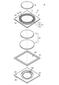
- FIG. 1 is an exploded perspective view of the fluid control device according to the first embodiment.
- FIG. 2 is a side sectional view showing the configuration of the fluid control device according to the first embodiment.
- FIG. 3 is an enlarged view of a region including the outer peripheral end of the first flat plate of the fluid control device according to the first embodiment.
- FIG. 4A is an enlarged view showing the fluid flow and the behavior of the valve member in the first state
- FIG. 4B is an enlarged view showing the fluid flow and the behavior of the valve member in the second state.
- FIG. 5 is a side sectional view showing the configuration of the fluid control device according to the second embodiment.
- FIG. 6A is a side sectional view showing the configuration of the fluid control device according to the third embodiment, and FIG.
- FIG. 6B is an enlargement of a region including the outer peripheral end of the first flat plate of the fluid control device. It is a figure.
- FIG. 7 is a side sectional view showing the configuration of the fluid control device according to the fourth embodiment.
- FIG. 8A is a plan view of a plate member to which a drive body is mounted in the fluid control device according to the fifth embodiment, and
- FIG. 8B is a location of one connecting member of the fluid control device. It is an enlarged plan view.
- FIG. 9 is an enlarged view of a region including the outer peripheral end of the first flat plate of the fluid control device according to the sixth embodiment and the connecting member.
- FIGS. 10 (A) and 10 (B) are enlarged perspective views of a region including an outer peripheral end of a first flat plate of the fluid control device according to the sixth embodiment and a connecting member.
- FIG. 11 is an enlarged view of a region including the outer peripheral end of the first flat plate of the fluid control device according to the seventh embodiment and the connecting member.
- FIG. 12 is an enlarged view of a region including the outer peripheral end of the first flat plate of the fluid control device according to the eighth embodiment and the connecting member.
- FIG. 13 is an enlarged view of a region including the outer peripheral end of the first flat plate of the fluid control device according to the ninth embodiment and the connecting member.
- FIG. 14 is an enlarged view of a region including the outer peripheral end of the first flat plate and the connecting member of the fluid control device according to the tenth embodiment.
- FIG. 1 is an exploded perspective view of the fluid control device according to the first embodiment.
- FIG. 2 is a side sectional view showing the configuration of the fluid control device according to the first embodiment.
- FIG. 3 is an enlarged view of a region including the outer peripheral end of the first flat plate of the fluid control device according to the first embodiment.
- the shape of each component is partially or wholly exaggerated as appropriate.
- viewing from a direction orthogonal to the main surface with respect to the component having the main surface is referred to as plan view.
- the fluid control device 10 includes a plate member 20, a drive body 30, a plate member 40, a side wall member 50, and a valve member 60.
- the plate member 20 is made of a metal plate or the like, and has a main surface 201 and a main surface 202.
- the plate member 20 includes a first flat plate 21, a frame body 22, and a plurality of connecting members 23.
- the first flat plate 21, the frame body 22, and the plurality of connecting members 23 are integrally formed using, for example, one flat plate.
- the first flat plate 21 has a plate shape.
- the first flat plate 21 has an outer peripheral portion including the outer peripheral end 210 and a central portion on the center side of the outer peripheral portion.
- the central part is thicker than the outer peripheral part.
- the shape of the first flat plate 21 in a plan view is circular.
- the central portion of the first flat plate 21 protrudes on the main surface 202 side.
- the main surface 201 is flat at the central portion and the outer peripheral portion including the outer peripheral end.
- the frame body 22 is a flat plate, and the shape of the frame body 22 in a plan view is a square.
- An opening is formed in the frame body 22.
- the opening penetrates the flat plate constituting the frame 22 in the thickness direction.
- the opening is circular in a plan view, has a shape similar to the outer peripheral shape of the first flat plate 21, and is larger than the outer peripheral shape of the first flat plate 21.
- the center of the frame 22 and the center of the opening coincide with each other.
- the first flat plate 21 is arranged inside the opening of the frame body 22. At this time, the center of the opening coincides with the center of the first flat plate 21. Since the area of the first flat plate 21 is smaller than the area of the opening of the frame body 22, even if the first flat plate 21 is arranged inside the opening of the frame body 22, the outer peripheral edge of the first flat plate 21 and the frame body 22 An opening remains between them.
- the plurality of connecting members 23 each have a beam shape.
- the plurality of connecting members 23 are arranged in the opening between the first flat plate 21 and the frame body 22.
- the plurality of connecting members 23 are arranged at intervals from each other along the outer peripheral end 210 of the first flat plate 21.
- Each of the plurality of connecting members 23 includes a first connecting portion 231, a second connecting portion 232, and a third connecting portion 233.
- the first connecting portion 231 has a shape extending along the radial direction.
- the radial direction is a direction toward the outside from the outer peripheral end 210 of the first flat plate 21.
- the second connecting portion 232 has an arc shape extending along the outer peripheral end 210 of the first flat plate 21 in a plan view (viewed in a direction orthogonal to the main surface 201 and the main surface 202).
- the third connecting portion 233 has a shape extending along the radial direction.
- One end of the first connecting portion 231 in the extending direction is connected to the outer peripheral end 210 of the first flat plate 21.
- the other end of the first connecting portion 231 in the extending direction is connected to substantially the center of the second connecting portion 232 in the extending direction.
- Both ends of the second connecting portion 232 in the extending direction are connected to the frame body 22 via the third connecting portion 233.
- the plurality of connecting members 23 have an opening 241 configured to include a region on the first flat plate 21 side of the second connecting portion 232 and a frame body 22 side of the second connecting portion 232.
- the first flat plate 21 and the frame 22 are connected so as to have an opening 242 of the region.
- These openings 241 and 242 correspond to the "first opening" of the present invention.
- the first flat plate 21 is supported in a state where bending vibration is possible with respect to the frame body 22 via a plurality of connecting members 23.
- the drive body 30 is, for example, a piezoelectric element, and is mounted on the first flat plate 21. More specifically, the drive body 30 is mounted on the central portion of the first flat plate 21.
- the plate member 40 has a main surface 401 and a main surface 402.
- the plate member 40 has a recess recessed from the main surface 401.
- a plurality of through holes 400 are formed at the bottom of the recess.
- the plurality of through holes 400 are arranged in a circle in a plan view (viewed in a direction orthogonal to the main surface 401 and the main surface 402).
- the diameter of the circle in which the plurality of through holes 400 are arranged is smaller than the diameter of the first flat plate 21.
- This plate member 40 corresponds to the "second flat plate" of the present invention.
- the plate member 40 is arranged at a distance from the plate member 20 so that the main surface 401 faces the main surface 201. At this time, the plate member 40 is arranged so that the plurality of through holes 400 overlap the first flat plate 21.
- the side wall member 50 is an annular shape having a hollow 500, and is arranged between the plate member 20 and the plate member 40.
- the side wall member 50 is connected to the frame body 22 and the plate member 40.
- a hollow chamber surrounded by the plate member 20, the side wall member 50, and the plate member 40 is formed and functions as the pump chamber 100.
- the pump chamber 100 communicates with the external space on the plate member 40 side of the fluid control device 10 by a plurality of through holes 400. Further, the pump chamber 100 communicates with the external space on the plate member 20 side of the fluid control device 10 by the plurality of openings 241 and 242.
- the valve member 60 includes a valve membrane 61 and a fixed layer 62.
- the valve membrane 61 and the fixed layer 62 are circular. That is, the outer shape of the valve membrane 61 and the outer shape of the fixed layer 62 are the outer shape of the first flat plate 21 (the shape of the outer peripheral end) and the shape of connecting the plurality of second connecting portions 232 of the connecting member 23. , Is a similar figure. Further, the outer shape of the valve membrane 61 and the outer shape of the fixed layer 62 are larger than the outer shape of the first flat plate 21.
- the valve membrane 61 is more easily curved than the fixed layer 62.
- the fixed layer 62 is more easily curved than the first flat plate 21.
- the relationship between these bendability is adjusted by the material and thickness of the valve membrane 61, the fixing layer 62, and the first flat plate 21.
- the first flat plate 21 is made of metal, and the fixed layer 62 has a higher flexural modulus than the valve membrane 61. Further, the fixed layer 62 is thicker than the valve membrane 61.
- the valve membrane 61 is fixed to the main surface 201 of the first flat plate 21 by the fixing layer 62. At this time, the center of the valve membrane 61, the center of the fixed layer 62, and the center of the first flat plate 21 substantially coincide with each other. At this time, since the outer shape of the valve membrane 61 and the outer shape of the fixed layer 62 are larger than the outer shape of the first flat plate 21, the valve member 60 having the outer shape of the valve membrane 61 and the outer shape of the fixed layer 62 , Has a protruding portion protruding outward from the outer peripheral end of the first flat plate 21.
- the diameter of the valve membrane 61 is larger than the diameter of the fixed layer 62. Therefore, in the valve membrane 61, the circular region on the center side is fixed, and the ring-shaped region on the outer end 610 side is not fixed. In other words, the valve membrane 61 is fixed to the first flat plate 21 by the fixing layer 62 in a state where the outer end 610 is not fixed.
- the portion consisting of only the valve membrane 61 corresponds to the "first portion of the valve member" of the present invention, and the laminated portion of the valve membrane 61 and the fixed layer 62 corresponds to the "second portion of the valve member” of the present invention.
- the portion where the fixed layer 62 and the first flat plate 21 are in contact with each other corresponds to the "fixed portion" of the present invention.
- the diameter of the fixed layer 62 is larger than the diameter of the first flat plate 21. Therefore, as shown in FIGS. 2 and 3, the outer end 620 of the fixed layer 62 is located outside the outer peripheral end 210 of the first flat plate 21. In other words, in plan view, the outer end 620 of the fixed layer 62 overlaps the opening 241. In other words, the connection portion (boundary portion) between the first portion of the valve member and the second portion of the valve member does not overlap with the first flat plate 21 in a plan view of the valve member, and the outer circumference of the first flat plate 21 is not overlapped. It is located outward of the end 210 and overlaps the opening 241.
- FIG. 4A is an enlarged view showing the fluid flow and the behavior of the valve member in the first state
- FIG. 4B is an enlarged view showing the fluid flow and the behavior of the valve member in the second state.
- the fluid is sucked into the pump chamber 100 from the outside on the plate member 40 side through the plurality of through holes 400.
- the fluid flows from the central portion of the first flat plate 21 toward the outer peripheral end 210 side (side wall member 50 side) in the pump chamber 100.
- valve membrane 61 The central side of the valve membrane 61 is fixed, and the outer end 610 of the valve membrane 61 is not fixed. Therefore, the valve membrane 61 is curved toward the first flat plate 21 side, in other words, the opening 241 and the connecting member 23 side by the fluid. As a result, the fluid flows from the pump chamber 100 to the opening 241 and is discharged from the opening 241 to the outside on the plate member 20 side. The fluid is also discharged to the outside of the plate member 20 side from the opening 242.
- the fluid is sucked into the pump chamber 100 from the outside on the plate member 20 side through the openings 241 and 242.
- the fluid tends to flow in the pump chamber 100 from the outer peripheral end 210 side (side wall member 50 side) of the first flat plate 21 toward the central portion side of the first flat plate 21.
- valve membrane 61 is curved toward the plate member 40 by the fluid. Then, the portion of the valve membrane 61 having a predetermined area on the outer end 610 side comes into contact with the main surface 401 of the plate member 40. This prevents the fluid from flowing to the center side of the pump chamber 100. Therefore, the fluid is prevented from being discharged to the outside on the plate member 40 side without reaching the plurality of through holes 400.
- the fluid control device 10 has a rectifying action for flowing the fluid in one direction.
- the fluid control device 10 further has the following features.
- the thickness D602 of the valve member 60 at the position overlapping the outer peripheral end 210 of the first flat plate 21 is thicker than the thickness D601 of the outer end 610 (D602> D601). ..
- the portion in contact with the corner portion of the outer peripheral end 210 of the first flat plate 21 is a portion having a thickness D602. be. That is, a portion thicker than the portion including the outer end 610 composed of only the valve membrane 61 contacts the corner portion of the outer peripheral end 210 of the first flat plate 21.
- the portion of the valve member 60 that comes into contact with the corner portion of the outer peripheral end 210 of the first flat plate 21 is harder than the outer end 610 and is less likely to be worn.
- the fluid control device 10 can suppress wear and breakage of the valve member 60.
- the laminated portion of the valve membrane 61 and the fixed layer 62 in the valve member 60 is difficult to bend.
- the laminated portion is difficult to bend, it is more easily curved than the first flat plate 21. Therefore, by appropriately setting the distance at which the fixed layer 62 protrudes from the outer peripheral end 210 of the first flat plate 21 and the distance at which the valve membrane 61 protrudes from the outer end 620 of the fixed layer 62, the valve member 60 is rectified. The decrease in action can be suppressed. That is, the fluid control device 10 is excellent in reliability by suppressing wear and breakage, and can realize a good rectifying action.
- the bending stress related to the valve membrane 61 is dispersed by bending the fixed layer 62. Therefore, it is possible to suppress peeling between the fixed layer 62 and the valve membrane 61 and cracks generated in the valve membrane 61 at the outer end 620 of the fixed layer 62.
- the fixed layer 62 is thicker than the valve membrane 61, but the present invention is not limited to this, and the portion of the valve member 60 in contact with the corner portion of the outer peripheral end 210 of the first flat plate 21 is formed. It suffices to be thicker than the portion including the outer peripheral edge that mainly realizes the rectifying action.
- the portion of the valve member 60 that comes into contact with the corner portion of the outer peripheral end 210 of the first flat plate 21 is more easily bent than the first flat plate 21, and includes the outer peripheral end of the valve member 60 that mainly realizes a rectifying action. May be even easier to bend than the portion of the first flat plate 21 that contacts the corner of the outer peripheral end 210.
- the aspect in which the fixed layer 62 protrudes from the outer peripheral end 210 of the first flat plate 21 is shown.
- the outer end 620 of the fixed layer 62 and the outer peripheral end 210 of the first flat plate 21 may coincide with each other.
- the outer end 620 of the fixed layer 62 is the first flat plate. It is possible to prevent the 21 from being on the central side of the outer peripheral end 210.
- the shape of the outer peripheral end 210 of the first flat plate 21, the shape of the outer end 620 of the fixed layer 62, and the shape of the outer end 610 of the valve membrane 61 are similar and circular. Further, the arrangement of the plurality of through holes 400 is also circular. As a result, the flow of the fluid becomes substantially uniform in all directions in the plan view, and the efficiency of the fluid control device 10 is improved.
- FIG. 5 is a side sectional view showing the configuration of the fluid control device according to the second embodiment.
- the fluid control device 10A according to the second embodiment is different from the fluid control device 10 according to the first embodiment in that a recess 241A is provided instead of the opening 241.
- Other configurations of the fluid control device 10A are the same as those of the fluid control device 10, and the description of the same parts will be omitted.
- the recess 241A is arranged between the first flat plate 21 and the second connecting portion 232 of the connecting member 23.
- the recess 241A has a shape recessed from the main surface 201 side of the plate member 20.
- the recess 241A has a shape in which the opening portion on the side opposite to the valve member 60 side in the opening 241 according to the first embodiment is closed.
- the fluid control device 10A can suppress wear and breakage of the valve member 60, similarly to the fluid control device 10.
- FIG. 6A is a side sectional view showing the configuration of the fluid control device according to the third embodiment
- FIG. 6B is an enlargement of a region including the outer peripheral end of the first flat plate of the fluid control device. It is a figure.
- the fluid control device 10B according to the third embodiment has a valve member 60B configuration with respect to the fluid control device 10 according to the first embodiment. different.
- Other configurations of the fluid control device 10B are the same as those of the fluid control device 10, and the description of the same parts will be omitted.
- the valve member 60B includes a valve membrane 61B and a fixed layer 62B.
- the valve membrane 61B is fixed to the main surface 201 of the first flat plate 21 by the fixing layer 62B.
- the outer shape of the fixed layer 62B is smaller than the outer shape of the first flat plate 21. More specifically, the diameter of the fixed layer 62B is smaller than the diameter of the first flat plate 21.
- the valve membrane 61 has a first portion including an outer end 610 and a second portion on the central side of the first portion.
- the thickness D602B of the second portion is thicker than the thickness D601 of the first portion.
- the connecting portion (the portion where the thickness changes) between the second portion and the first portion is located outside the outer peripheral end 210 of the first flat plate 21.
- the portion of the valve membrane 61B that overlaps with the outer peripheral end 210 of the first flat plate 21 is the second portion. That is, it becomes a thick portion in the valve membrane 61B.
- the position of the outer end of the second portion is preferably separated from the outer peripheral end 210 of the first flat plate 21 outward by a thickness D62 of the fixed layer 62B. ..
- the second portion more reliably contacts the corner portion of the outer peripheral end 210. Therefore, wear and breakage of the valve membrane 61B can be suppressed more reliably.
- FIG. 7 is a side sectional view showing the configuration of the fluid control device according to the fourth embodiment.
- the fluid control device 10C according to the fourth embodiment differs from the fluid control device 10 according to the first embodiment mainly in the shape and arrangement of the valve member 60C. Further, the fluid control device 10C is also different from the fluid control device 10 in the shapes of the plate member 20C and the plate member 40C. Other configurations of the fluid control device 10C are the same as those of the fluid control device 10, and the description of the same parts will be omitted.
- the fluid control device 10C includes a plate member 20C, a plate member 40C, and a valve member 60C.
- the plate member 20C includes a first flat plate 21C.
- the first flat plate 21C has a uniform thickness.
- the plate member 40C has a uniform thickness.
- a through hole 400C is formed in the center of the plate member 40C in a plan view.
- the through hole 400C penetrates the plate member 40C in the thickness direction (direction orthogonal to the main surface 401 and the main surface 402).
- the through hole 400C is, for example, cylindrical.
- the valve member 60C includes a valve membrane 61C and a fixed layer 62C.
- the valve membrane 61C is annular and has a circular opening 619.
- the outer diameter (diameter) of the valve membrane 61C is larger than the diameter of the through hole 400C.
- the diameter of the opening 619 is smaller than the diameter of the through hole 400C.
- the outer diameter (diameter) of the fixed layer 62C is larger than the diameter of the through hole 400C.
- the diameter of the opening 629 is smaller than the diameter of the through hole 400C and larger than the diameter of the opening 619 of the valve membrane 61C.
- the valve membrane 61C is fixed to the main surface 401 of the plate member 40C on the pump chamber side via the fixed layer 62C. At this time, in a plan view, the center of the opening 619 of the valve membrane 61C, the center of the opening 629 of the fixed layer 62C, and the center of the through hole 400 substantially coincide with each other.
- the valve membrane 61C is fixed to the main surface 401 via the fixing layer 62C in the region on the outer end side. Therefore, in the fluid control device 10C, when the fluid is sucked from the openings 241 and 242, the valve member 60C is curved so as to enter the through hole 400C. Then, the fluid is discharged to the outside from the through hole 400C. On the other hand, when the fluid is sucked from the through hole 400C, the valve member 60C is curved toward the plate member 20C, and the region of the valve membrane 61C on the inner end 610C side abuts on the main surface 201 of the plate member 20C. As a result, the fluid does not flow toward the outer peripheral end 210 of the plate member 20C.
- the fluid control device 10C has a rectifying action for flowing the fluid in one direction.
- the inner end 610C of the valve membrane 61C and the inner end 620C of the fixed layer 62C are inside (center side) of the through hole 400C with respect to the wall 410 of the through hole 400C. Further, the inner end 610C of the valve membrane 61C is further inside than the inner end 620C of the fixed layer 62C.
- the fluid control device 10C can suppress wear and breakage of the valve membrane 61C.
- FIG. 8A is a plan view of a plate member to which a drive body is mounted in the fluid control device according to the fifth embodiment
- FIG. 8B is a location of one connecting member of the fluid control device. It is an enlarged plan view.
- the fluid control device according to the fifth embodiment has a connecting member 23D of the plate member 20D to the fluid control device 10 according to the first embodiment. It differs in the shape of.
- the other configuration of the fluid control device according to the fifth embodiment is the same as that of the fluid control device 10, and the description of the same parts will be omitted.
- the connecting member 23D includes a first connecting portion 231D, a second connecting portion 232, and a third connecting portion 233.
- the first connecting portion 231D includes an inner end portion 2311, a middle end portion 2312, and an outer end portion 2313.
- the inner end portion 2311 is connected to the outer peripheral end 210 of the first flat plate 21.
- the outer end portion 2313 is connected to the second connecting portion 232.
- the middle end portion 2312 is connected to the inner end portion 2311 and the outer end portion 2313.
- the middle joint portion 2312 has a shape in which the width becomes wider from the end on the inner end portion 2311 side to the end on the outer end portion 2313 side.
- the inner end portion 2311 has no corner portion at the connection portion with the first flat plate 21.
- the inner end portion 2311 has a shape in which the width gradually narrows as it approaches the intermediate portion 2312. Further, the inner end portion 2311 is connected to the intermediate portion 2312 without having a corner portion.
- the outer end portion 2313 does not have a corner portion at the connection portion with the second connecting portion 232.
- the outer end portion 2313 has a shape in which the width gradually narrows as it approaches the intermediate portion 2312. Further, the outer end portion 2313 is connected to the intermediate portion 2312 without having a corner portion.
- the outer end 620 of the fixed layer 62 and the outer end 610 of the valve membrane 61 do not come into contact with the corners. Therefore, wear and breakage of the valve membrane 61 and the fixed layer 62 can be further suppressed.
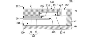
- FIG. 9 is an enlarged view of a region including the outer peripheral end of the first flat plate of the fluid control device according to the sixth embodiment and the connecting member.
- 10 (A) and 10 (B) are enlarged perspective views of a region including an outer peripheral end of a first flat plate of the fluid control device according to the sixth embodiment and a connecting member.
- FIG. 10A shows a state in which the valve membrane is arranged
- FIG. 10B shows a state in which the valve membrane is removed.
- the fluid control device 10E according to the sixth embodiment is a connecting member to the fluid control device 10 according to the first embodiment. It differs in the shape of the first connecting portion 231E.
- Other configurations of the fluid control device 10E are the same as those of the fluid control device 10, and the description of the same parts will be omitted.
- the first connecting portion 231E has a recess 2310 recessed from the main surface 201 side of the first flat plate 21 with respect to the first flat plate 21 and the second connecting portion 232. In other words, when the valve member 60 is viewed in a plan view, the first connecting portion 231E overlaps the outer end 610 of the valve member 60 and the first portion of the valve member 60 (a portion composed of only the valve membrane 61). 1
- the flat plate 21 has a recess 2310 recessed from the surface on which the valve member 60 is arranged.
- the fluid control device 10E can further suppress wear and breakage of the valve membrane 61.
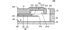
- FIG. 11 is an enlarged view of a region including the outer peripheral end and the connecting portion of the first flat plate of the fluid control device according to the seventh embodiment.
- the fluid control device 10F according to the seventh embodiment differs from the fluid control device 10E according to the sixth embodiment in the shape of the first connecting portion 231F of the connecting member.
- Other configurations of the fluid control device 10F are the same as those of the fluid control device 10E, and the description of the same parts will be omitted.
- the first connecting portion 231F has a curved surface at the opening on the first flat plate 21 side in the recess 2310.
- the recess 2310 has a shape that gradually becomes deeper from the end on the first flat plate 21 side toward the center of the recess 2310.
- the fluid control device 10F can further suppress wear and breakage of the valve membrane 61.
- FIG. 12 is an enlarged view of a region including the outer peripheral end of the first flat plate of the fluid control device according to the eighth embodiment and the connecting member.
- the fluid control device 10G according to the eighth embodiment differs from the fluid control device 10E according to the sixth embodiment in the shape of the first connecting portion 231G of the connecting member.
- Other configurations of the fluid control device 10G are the same as those of the fluid control device 10E, and the description of the same parts will be omitted.
- the first connecting portion 231 is curved in the middle of the direction connecting the first flat plate 21 and the second connecting portion 232 so as to project toward the main surface 202 side of the first flat plate 21.
- the first connecting portion 231G can easily secure a predetermined thickness while having the recess 2310. As a result, the first connecting portion 231G can secure a predetermined strength. Therefore, the fluid control device 10G can further suppress wear and tear of the valve membrane 61, and can suppress a decrease in reliability.
- FIG. 13 is an enlarged view of a region including the outer peripheral end of the first flat plate of the fluid control device according to the ninth embodiment and the connecting member.
- the fluid control device 10H according to the ninth embodiment differs from the fluid control device 10E according to the sixth embodiment in the shapes of the first flat plate 21H and the recess 2310H.
- Other configurations of the fluid control device 10H are the same as those of the fluid control device 10E, and the description of the same parts will be omitted.
- the shape of the first connecting portion 231H of the fluid control device 10H is the same as that of the first connecting portion 231E of the fluid control device 10E, and the description thereof will be omitted.
- the first flat plate 21H has a concave portion recessed from the main surface 201 side at the outer peripheral end 210.
- the recess formed in the first flat plate 21H communicates with the recess formed in the first connecting portion 231H to form the recess 2310H.
- the recess 2310H extends from the first connecting portion 231H to the inside of the outer peripheral end 210 of the first flat plate 21H.
- the fluid control device 10H can further suppress wear and breakage of the valve membrane 61.
- FIG. 14 is an enlarged view of a region including the outer peripheral end of the first flat plate and the connecting member of the fluid control device according to the tenth embodiment.
- the fluid control device 10I according to the tenth embodiment differs from the fluid control device 10E according to the sixth embodiment in the connection mode between the first flat plate 21I and the connecting member.
- Other configurations of the fluid control device 10I are the same as those of the fluid control device 10E, and the description of the same parts will be omitted.
- the first connecting portion 231I is connected to the main surface 202 near the outer peripheral end 210 of the first flat plate 21H. In such a configuration, the depth of the recess 2310 is equal to or greater than the thickness of the first flat plate 21I.
- the fluid control device 10I can further suppress wear and breakage of the valve membrane 61.
- the first flat plate is circular and the valve member is circular or annular.
- these may be polygons, more preferably regular polygons with a large number of angles.
- the circular shape allows the fluid control device to improve efficiency.
- the first flat plate and the valve membrane show a similar figure, but for example, a combination such as a circular shape and a regular polygonal shape may be used.
- the similarity shape allows the fluid control device to improve efficiency.
- the second connecting portion of the connecting member and the valve membrane have a similar shape, the passage efficiency of the fluid at the opening 241 is improved, and the efficiency of the fluid control device can be improved.
- the mode in which the drive body is installed on the first flat plate is shown, but the mode in which the drive body is installed on the plate member (second flat plate) may be used.
Abstract
A fluid control device (10) comprises: a first flat plate (21); a frame body (22) that is disposed on the outside of an outer peripheral edge (210) of the first flat plate (21) with openings (241, 242) therebetween; a joining member (23) that joins the first plate (21) and the frame body (22) with each other; a plate member (40) provided with through holes (400) in portions facing the first flat plate (21); and a valve member (60) for regulating a fluid. An outer edge (610) of the valve member (60) protrudes further outside than the outer peripheral edge (210) of the first flat plate (21). The inner edge side of the valve member (60), which is located on the central side of the first flat plate (21), is fixed to the first flat plate (21) while the outer edge (610) is not fixed thereto. The valve member (60) has a first portion on the outer edge side and a second portion on the inner edge side of the first portion. The thickness of the second portion is thicker than that of the first portion. In a plan view, the second portion overlaps with the outer peripheral edge (210) of the first flat plate (21).
Description
本発明は、流体を一方向に搬送する流体制御装置に関する。
The present invention relates to a fluid control device that conveys a fluid in one direction.
特許文献1には、ポンプとバルブとが一体形成された流体制御装置が記載されている。ポンプは、一面が振動板によって形成されたポンプ室を有する。バルブは、ポンプ室に連通するバルブ室を有する。
Patent Document 1 describes a fluid control device in which a pump and a valve are integrally formed. The pump has a pump chamber, one side of which is formed by a diaphragm. The valve has a valve chamber that communicates with the pump chamber.
バルブ室内には、弁膜が配置されている。弁膜が流体の流れによってバルブ室内を移動することによって、流体は整流される。
A valve membrane is arranged in the valve chamber. The fluid is rectified as the valve membrane moves through the valve chamber by the flow of the fluid.
特許文献1に示す流体制御装置のように、弁膜を用いる構成として、ポンプ室内に弁膜を配置する態様も考えられる。この場合、流体の流れる方向に沿った弁膜の一端をポンプの内壁に固定し、他端を可動にする。流体が特定方向に流れると、弁膜の他端は、弁膜が固定された壁面側に移動し、流体は、搬送される。一方、流体が逆方向に流れようとすると、弁膜の他端は、弁膜が固定された壁面と対向する壁面側に移動し、この壁面に当接する。これにより、流体の流れは阻止される。したがって、流体は、整流される。
As in the fluid control device shown in Patent Document 1, it is conceivable that the valve membrane is arranged in the pump chamber as a configuration using the valve membrane. In this case, one end of the valve membrane along the flow direction of the fluid is fixed to the inner wall of the pump, and the other end is movable. When the fluid flows in a specific direction, the other end of the valve membrane moves to the wall surface side where the valve membrane is fixed, and the fluid is conveyed. On the other hand, when the fluid tries to flow in the opposite direction, the other end of the valve membrane moves to the wall surface side facing the wall surface to which the valve membrane is fixed and abuts on the wall surface. This blocks the flow of fluid. Therefore, the fluid is rectified.
しかしながら、このようなポンプ室内に弁膜を配置する構成では、弁膜の他端に近い部分が、ポンプ室を形成する壁の外周端の角部に接触することがある。そして、このような接触が起こると、弁膜が摩耗し、破損するという問題が生じる。
However, in such a configuration in which the valve membrane is arranged in the pump chamber, the portion near the other end of the valve membrane may come into contact with the corner portion of the outer peripheral end of the wall forming the pump chamber. When such contact occurs, there arises a problem that the valve membrane is worn and damaged.
したがって、本発明の目的は、弁膜の摩耗、破損を抑制できる流体制御装置を提供することにある。
Therefore, an object of the present invention is to provide a fluid control device capable of suppressing wear and tear of the valve membrane.
この発明の流体制御装置は、外周端よりも外側に第1開口を有する第1平板と、第1平板の外周端よりも外側に配置された枠体と、第1平板と枠体とを連結する連結部材と、第1平板、枠体、および、連結部材に対向し、第1平板と対向する部分に第2開口を有する第2平板と、枠体と第2平板とを接続し、第1平板と第2平板とが対向する領域を含む中空室を形成する側壁部材と、第1平板に装着された駆動体と、第1平板におけるポンプ室側の第1面に設置され、流体を整流する弁部材と、を備える。
The fluid control device of the present invention connects a first flat plate having a first opening outside the outer peripheral end, a frame body arranged outside the outer peripheral end of the first flat plate, and the first flat plate and the frame body. The first flat plate, the frame body, and the second flat plate facing the connecting member and having a second opening in the portion facing the first flat plate, and the frame body and the second flat plate are connected to each other. A side wall member forming a hollow chamber including a region where the first flat plate and the second flat plate face each other, a drive body mounted on the first flat plate, and a fluid installed on the first surface of the first flat plate on the pump chamber side. It is provided with a valve member for rectifying.
弁部材は、第1平板の外周端側にある外端が外周端よりも外方に突出している。弁部材は、第1平板の中心側にある内端側が第1平板に固定され、外端が固定されていない。弁部材は、外端側の部分を構成する第1厚みの第1部分と、第1部分の内端側の部分を構成する第2厚みの第2部分と、を有する。第2厚みは、第1厚みよりも厚い。第2部分は、外周端に重なっている。
The outer end of the valve member on the outer peripheral end side of the first flat plate protrudes outward from the outer peripheral end. In the valve member, the inner end side on the center side of the first flat plate is fixed to the first flat plate, and the outer end is not fixed. The valve member has a first portion having a first thickness that constitutes a portion on the outer end side, and a second portion having a second thickness that constitutes a portion on the inner end side of the first portion. The second thickness is thicker than the first thickness. The second portion overlaps the outer peripheral edge.
この構成では、弁部材が第1平板側に湾曲しても、第1平板の角部には、第2部分が接触する。第2部分は、第1部分よりも厚いので、第1部分が第1平板の角部に接触するよりも、弁部材は摩耗、破損し難い。また、第1部分の厚みが薄いことで、弁部材に必要な整流機能の低下は抑制される。
In this configuration, even if the valve member is curved toward the first flat plate, the second portion comes into contact with the corner portion of the first flat plate. Since the second portion is thicker than the first portion, the valve member is less likely to be worn or damaged than when the first portion contacts the corner portion of the first flat plate. Further, since the thickness of the first portion is thin, the deterioration of the rectifying function required for the valve member is suppressed.
この発明によれば、弁膜の摩耗、破損を抑制できる。
According to this invention, wear and breakage of the valve membrane can be suppressed.
(第1の実施形態)
本発明の第1の実施形態に係る流体制御装置について、図を参照して説明する。図1は、第1の実施形態に係る流体制御装置の分解斜視図である。図2は、第1の実施形態に係る流体制御装置の構成を示す側面断面図である。図3は、第1の実施形態に係る流体制御装置の第1平板の外周端を含む領域の拡大図である。本実施形態を含む各実施形態の各図では、流体制御装置の構成を分かり易くするため、それぞれの構成要素の形状を部分的または全体として、適宜誇張して記載している。なお、以下の実施形態では、主面を有する構成要素に対して、主面に直交する方向から視ることを、平面視と称する。 (First Embodiment)
The fluid control device according to the first embodiment of the present invention will be described with reference to the drawings. FIG. 1 is an exploded perspective view of the fluid control device according to the first embodiment. FIG. 2 is a side sectional view showing the configuration of the fluid control device according to the first embodiment. FIG. 3 is an enlarged view of a region including the outer peripheral end of the first flat plate of the fluid control device according to the first embodiment. In each figure of each embodiment including the present embodiment, in order to make the configuration of the fluid control device easy to understand, the shape of each component is partially or wholly exaggerated as appropriate. In the following embodiments, viewing from a direction orthogonal to the main surface with respect to the component having the main surface is referred to as plan view.
図1、図2、図3に示すように、流体制御装置10は、板部材20、駆動体30、板部材40、側壁部材50、および、弁部材60を備える。
As shown in FIGS. 1, 2, and 3, the fluid control device 10 includes a plate member 20, a drive body 30, a plate member 40, a side wall member 50, and a valve member 60.
(板部材20の構成)
板部材20は、金属板等からなり、主面201と主面202とを有する。板部材20は、第1平板21、枠体22、および、複数の連結部材23を備える。第1平板21、枠体22、および、複数の連結部材23は、例えば、1枚の平板を用いて、一体に形成される。 (Structure of plate member 20)
Theplate member 20 is made of a metal plate or the like, and has a main surface 201 and a main surface 202. The plate member 20 includes a first flat plate 21, a frame body 22, and a plurality of connecting members 23. The first flat plate 21, the frame body 22, and the plurality of connecting members 23 are integrally formed using, for example, one flat plate.
板部材20は、金属板等からなり、主面201と主面202とを有する。板部材20は、第1平板21、枠体22、および、複数の連結部材23を備える。第1平板21、枠体22、および、複数の連結部材23は、例えば、1枚の平板を用いて、一体に形成される。 (Structure of plate member 20)
The
第1平板21は、板状である。第1平板21は、外周端210を含む外周部と外周部よりも中心側の中央部を有する。中央部は、外周部よりも厚い。第1平板21を平面視した形状(厚み方向に視た形状)は、円形である。第1平板21は、主面202側において、中央部が突出している。逆に、第1平板21では、主面201は、中央部分と外周端を含む外周部分とで平坦である。
The first flat plate 21 has a plate shape. The first flat plate 21 has an outer peripheral portion including the outer peripheral end 210 and a central portion on the center side of the outer peripheral portion. The central part is thicker than the outer peripheral part. The shape of the first flat plate 21 in a plan view (shape in the thickness direction) is circular. The central portion of the first flat plate 21 protrudes on the main surface 202 side. On the contrary, in the first flat plate 21, the main surface 201 is flat at the central portion and the outer peripheral portion including the outer peripheral end.
枠体22は、平板であり、枠体22を平面視した形状は、正方形である。枠体22には、開口が形成されている。開口は、枠体22を構成する平板を厚み方向に貫通する。開口は、平面視して円形であり、第1平板21の外周形状と相似形で、第1平板21の外周形状よりも大きい。枠体22の中心と開口の中心とは一致する。
The frame body 22 is a flat plate, and the shape of the frame body 22 in a plan view is a square. An opening is formed in the frame body 22. The opening penetrates the flat plate constituting the frame 22 in the thickness direction. The opening is circular in a plan view, has a shape similar to the outer peripheral shape of the first flat plate 21, and is larger than the outer peripheral shape of the first flat plate 21. The center of the frame 22 and the center of the opening coincide with each other.
枠体22の開口の内部に、第1平板21が配置される。この際、開口の中心と、第1平板21の中心とは一致する。第1平板21の面積が枠体22の開口の面積よりも小さいことにより、枠体22の開口の内部に第1平板21を配置しても、第1平板21の外周端と枠体22との間には、開口が残る。
The first flat plate 21 is arranged inside the opening of the frame body 22. At this time, the center of the opening coincides with the center of the first flat plate 21. Since the area of the first flat plate 21 is smaller than the area of the opening of the frame body 22, even if the first flat plate 21 is arranged inside the opening of the frame body 22, the outer peripheral edge of the first flat plate 21 and the frame body 22 An opening remains between them.
複数の連結部材23は、それぞれに梁形状である。複数の連結部材23は、第1平板21と枠体22との間の開口に配置される。複数の連結部材23は、第1平板21の外周端210に沿って、互いに間隔をあけて配置される。
The plurality of connecting members 23 each have a beam shape. The plurality of connecting members 23 are arranged in the opening between the first flat plate 21 and the frame body 22. The plurality of connecting members 23 are arranged at intervals from each other along the outer peripheral end 210 of the first flat plate 21.
複数の連結部材23は、それぞれに、第1連結部231、第2連結部232、および、第3連結部233を備える。第1連結部231は、放射方向に沿って延びる形状である。放射方向とは、第1平板21の外周端210から外方に向かう方向である。第2連結部232は、平面視において(主面201および主面202に直交する方向に視て)、第1平板21の外周端210に沿って延びる円弧状である。第3連結部233は、放射方向に沿って延びる形状である。
Each of the plurality of connecting members 23 includes a first connecting portion 231, a second connecting portion 232, and a third connecting portion 233. The first connecting portion 231 has a shape extending along the radial direction. The radial direction is a direction toward the outside from the outer peripheral end 210 of the first flat plate 21. The second connecting portion 232 has an arc shape extending along the outer peripheral end 210 of the first flat plate 21 in a plan view (viewed in a direction orthogonal to the main surface 201 and the main surface 202). The third connecting portion 233 has a shape extending along the radial direction.
第1連結部231の延びる方向の一方端は、第1平板21の外周端210に接続する。第1連結部231の延びる方向の他方端は、第2連結部232の延びる方向の略中央に接続する。第2連結部232の延びる方向の両端は、第3連結部233を介して、枠体22に接続する。
One end of the first connecting portion 231 in the extending direction is connected to the outer peripheral end 210 of the first flat plate 21. The other end of the first connecting portion 231 in the extending direction is connected to substantially the center of the second connecting portion 232 in the extending direction. Both ends of the second connecting portion 232 in the extending direction are connected to the frame body 22 via the third connecting portion 233.
このような構成によって、複数の連結部材23は、第2連結部232よりも第1平板21側の領域を含むように構成された開口241と、第2連結部232よりも枠体22側の領域の開口242を有するように、第1平板21と枠体22とを連結する。これら開口241および開口242が、本発明の「第1開口」に対応する。
With such a configuration, the plurality of connecting members 23 have an opening 241 configured to include a region on the first flat plate 21 side of the second connecting portion 232 and a frame body 22 side of the second connecting portion 232. The first flat plate 21 and the frame 22 are connected so as to have an opening 242 of the region. These openings 241 and 242 correspond to the "first opening" of the present invention.
そして、この構成によって、第1平板21は、複数の連結部材23を介して、枠体22に対してベンディング振動可能な状態で支持される。
With this configuration, the first flat plate 21 is supported in a state where bending vibration is possible with respect to the frame body 22 via a plurality of connecting members 23.
駆動体30は、例えば、圧電素子であり、第1平板21に装着される。より具体的には、駆動体30は、第1平板21の中央部に装着される。
The drive body 30 is, for example, a piezoelectric element, and is mounted on the first flat plate 21. More specifically, the drive body 30 is mounted on the central portion of the first flat plate 21.
板部材40は、主面401と主面402とを有する。板部材40は、主面401から凹む凹部を有する。凹部の底には、複数の貫通孔400が形成されている。複数の貫通孔400は、平面視して(主面401および主面402に直交する方向に視て)、円形に配置される。複数の貫通孔400が配置される円の直径は、第1平板21の直径よりも小さい。この板部材40が、本発明の「第2平板」に対応する。
The plate member 40 has a main surface 401 and a main surface 402. The plate member 40 has a recess recessed from the main surface 401. A plurality of through holes 400 are formed at the bottom of the recess. The plurality of through holes 400 are arranged in a circle in a plan view (viewed in a direction orthogonal to the main surface 401 and the main surface 402). The diameter of the circle in which the plurality of through holes 400 are arranged is smaller than the diameter of the first flat plate 21. This plate member 40 corresponds to the "second flat plate" of the present invention.
板部材40は、主面401が主面201に対向するように、板部材20から距離を空けて配置される。この際、板部材40は、複数の貫通孔400が第1平板21に重なるように、配置される。
The plate member 40 is arranged at a distance from the plate member 20 so that the main surface 401 faces the main surface 201. At this time, the plate member 40 is arranged so that the plurality of through holes 400 overlap the first flat plate 21.
側壁部材50は、中空500を有する環状であり、板部材20と、板部材40との間に配置される。側壁部材50は、枠体22と、板部材40とに接続する。
The side wall member 50 is an annular shape having a hollow 500, and is arranged between the plate member 20 and the plate member 40. The side wall member 50 is connected to the frame body 22 and the plate member 40.
これにより、板部材20、側壁部材50、および、板部材40によって囲まれる中空室が形成され、ポンプ室100として機能する。ポンプ室100は、複数の貫通孔400によって、流体制御装置10の板部材40側の外部空間に連通する。また、ポンプ室100は、複数の開口241および開口242によって、流体制御装置10の板部材20側の外部空間に連通する。
As a result, a hollow chamber surrounded by the plate member 20, the side wall member 50, and the plate member 40 is formed and functions as the pump chamber 100. The pump chamber 100 communicates with the external space on the plate member 40 side of the fluid control device 10 by a plurality of through holes 400. Further, the pump chamber 100 communicates with the external space on the plate member 20 side of the fluid control device 10 by the plurality of openings 241 and 242.
弁部材60は、弁膜61と固定層62とを備える。弁膜61および固定層62は、円形である。すなわち、弁膜61の外形形状、および、固定層62の外形形状は、第1平板21の外形形状(外周端の形状)、および、連結部材23の複数の第2連結部232を繋げた形状と、相似形である。また、弁膜61の外形形状、および、固定層62の外形形状は、第1平板21の外形形状よりも大きい。
The valve member 60 includes a valve membrane 61 and a fixed layer 62. The valve membrane 61 and the fixed layer 62 are circular. That is, the outer shape of the valve membrane 61 and the outer shape of the fixed layer 62 are the outer shape of the first flat plate 21 (the shape of the outer peripheral end) and the shape of connecting the plurality of second connecting portions 232 of the connecting member 23. , Is a similar figure. Further, the outer shape of the valve membrane 61 and the outer shape of the fixed layer 62 are larger than the outer shape of the first flat plate 21.
弁膜61は、固定層62よりも湾曲し易い。固定層62は、第1平板21よりも湾曲し易い。これらの湾曲し易さの関係は、弁膜61、固定層62、および、第1平板21の材料および厚みによって調整される。例えば、第1平板21は、金属で有り、固定層62は、弁膜61よりも高い曲げ弾性率を有する。また、固定層62は、弁膜61よりも厚い。
The valve membrane 61 is more easily curved than the fixed layer 62. The fixed layer 62 is more easily curved than the first flat plate 21. The relationship between these bendability is adjusted by the material and thickness of the valve membrane 61, the fixing layer 62, and the first flat plate 21. For example, the first flat plate 21 is made of metal, and the fixed layer 62 has a higher flexural modulus than the valve membrane 61. Further, the fixed layer 62 is thicker than the valve membrane 61.
弁膜61は、固定層62によって、第1平板21の主面201に固定される。この際、弁膜61の中心、固定層62の中心、および、第1平板21の中心は、略一致する。この際、弁膜61の外形形状、および、固定層62の外形形状は、第1平板21の外形形状よりも大きいことにより、弁膜61の外形形状および固定層62の外形形状からなる弁部材60は、第1平板21の外周端よりも外方に突出する突出部を有する。
The valve membrane 61 is fixed to the main surface 201 of the first flat plate 21 by the fixing layer 62. At this time, the center of the valve membrane 61, the center of the fixed layer 62, and the center of the first flat plate 21 substantially coincide with each other. At this time, since the outer shape of the valve membrane 61 and the outer shape of the fixed layer 62 are larger than the outer shape of the first flat plate 21, the valve member 60 having the outer shape of the valve membrane 61 and the outer shape of the fixed layer 62 , Has a protruding portion protruding outward from the outer peripheral end of the first flat plate 21.
弁膜61の直径は、固定層62の直径よりも大きい。したがって、弁膜61は、中心側の円形の領域が固定され、外端610側の環形の領域が固定されない。言い換えれば、弁膜61は、外端610が固定されない状態で、固定層62によって、第1平板21に固定される。弁膜61のみからなる部分が、本発明の「弁部材の第1部分」に対応し、弁膜61と固定層62との積層部が、本発明の「弁部材の第2部分」に対応する。そして、固定層62と第1平板21とが当接している部分が、本発明の「固定部」に対応する。
The diameter of the valve membrane 61 is larger than the diameter of the fixed layer 62. Therefore, in the valve membrane 61, the circular region on the center side is fixed, and the ring-shaped region on the outer end 610 side is not fixed. In other words, the valve membrane 61 is fixed to the first flat plate 21 by the fixing layer 62 in a state where the outer end 610 is not fixed. The portion consisting of only the valve membrane 61 corresponds to the "first portion of the valve member" of the present invention, and the laminated portion of the valve membrane 61 and the fixed layer 62 corresponds to the "second portion of the valve member" of the present invention. The portion where the fixed layer 62 and the first flat plate 21 are in contact with each other corresponds to the "fixed portion" of the present invention.
固定層62の直径は、第1平板21の直径よりも大きい。したがって、図2、図3に示すように、固定層62の外端620は、第1平板21の外周端210よりも外方に位置する。言い換えれば、平面視において、固定層62の外端620は、開口241に重なる。さらに言い換えれば、弁部材の第1部分と弁部材の第2部分との接続部(境界部)は、弁部材を平面視して、第1平板21に重ならず、第1平板21の外周端210よりも外方に位置し、開口241に重なる。
The diameter of the fixed layer 62 is larger than the diameter of the first flat plate 21. Therefore, as shown in FIGS. 2 and 3, the outer end 620 of the fixed layer 62 is located outside the outer peripheral end 210 of the first flat plate 21. In other words, in plan view, the outer end 620 of the fixed layer 62 overlaps the opening 241. In other words, the connection portion (boundary portion) between the first portion of the valve member and the second portion of the valve member does not overlap with the first flat plate 21 in a plan view of the valve member, and the outer circumference of the first flat plate 21 is not overlapped. It is located outward of the end 210 and overlaps the opening 241.
このような構成において、流体制御装置10は、次のように、流体の整流を行う。図4(A)は、第1状態における流体の流れおよび弁部材の挙動を示す拡大図であり、図4(B)は、第2状態における流体の流れおよび弁部材の挙動を示す拡大図である。
In such a configuration, the fluid control device 10 rectifies the fluid as follows. FIG. 4A is an enlarged view showing the fluid flow and the behavior of the valve member in the first state, and FIG. 4B is an enlarged view showing the fluid flow and the behavior of the valve member in the second state. be.
図4(A)に示すように、流体制御装置10の第1状態では、流体は、板部材40側の外部から複数の貫通孔400を介してポンプ室100に吸入される。流体は、ポンプ室100内において、第1平板21の中央部から外周端210側(側壁部材50側)に向けて流れる。
As shown in FIG. 4A, in the first state of the fluid control device 10, the fluid is sucked into the pump chamber 100 from the outside on the plate member 40 side through the plurality of through holes 400. The fluid flows from the central portion of the first flat plate 21 toward the outer peripheral end 210 side (side wall member 50 side) in the pump chamber 100.
弁膜61の中心側が固定されており、弁膜61の外端610は固定されていない。したがって、弁膜61は、流体によって、第1平板21側、言い換えれば、開口241、および、連結部材23側に湾曲する。これにより、流体は、ポンプ室100から開口241に流れ、開口241から板部材20側の外部に吐出される。なお、流体は、開口242からも、板部材20側の外部に吐出される。
The central side of the valve membrane 61 is fixed, and the outer end 610 of the valve membrane 61 is not fixed. Therefore, the valve membrane 61 is curved toward the first flat plate 21 side, in other words, the opening 241 and the connecting member 23 side by the fluid. As a result, the fluid flows from the pump chamber 100 to the opening 241 and is discharged from the opening 241 to the outside on the plate member 20 side. The fluid is also discharged to the outside of the plate member 20 side from the opening 242.
図4(B)に示すように、流体制御装置10の第2状態では、流体は、板部材20側の外部から開口241および開口242を介してポンプ室100に吸入される。流体は、ポンプ室100内において、第1平板21の外周端210側(側壁部材50側)から第1平板21の中央部側に向けて流れようとする。
As shown in FIG. 4B, in the second state of the fluid control device 10, the fluid is sucked into the pump chamber 100 from the outside on the plate member 20 side through the openings 241 and 242. The fluid tends to flow in the pump chamber 100 from the outer peripheral end 210 side (side wall member 50 side) of the first flat plate 21 toward the central portion side of the first flat plate 21.
この場合、弁膜61は、流体によって、板部材40側に湾曲する。そして、弁膜61における外端610側の所定面積の部分は、板部材40の主面401に当接する。これにより、流体がポンプ室100の中央側に流れることは、阻止される。したがって、流体は、複数の貫通孔400に達することなく、流体が板部材40側の外部に吐出されることは、防止される。
In this case, the valve membrane 61 is curved toward the plate member 40 by the fluid. Then, the portion of the valve membrane 61 having a predetermined area on the outer end 610 side comes into contact with the main surface 401 of the plate member 40. This prevents the fluid from flowing to the center side of the pump chamber 100. Therefore, the fluid is prevented from being discharged to the outside on the plate member 40 side without reaching the plurality of through holes 400.
このように、流体制御装置10は、流体を一方向に流す整流作用を有する。
As described above, the fluid control device 10 has a rectifying action for flowing the fluid in one direction.
流体制御装置10は、さらに、次の特徴を有する。流体制御装置10では、上述の構成を備えることによって、弁部材60における、第1平板21の外周端210に重なる位置での厚みD602は、外端610の厚みD601よりも厚い(D602>D601)。
The fluid control device 10 further has the following features. In the fluid control device 10, by providing the above-mentioned configuration, the thickness D602 of the valve member 60 at the position overlapping the outer peripheral end 210 of the first flat plate 21 is thicker than the thickness D601 of the outer end 610 (D602> D601). ..
この構成では、図4(A)に示すように、弁膜61が第1平板21側に湾曲するとき、第1平板21の外周端210の角部に接触する部分は、厚みD602を有する部分である。すなわち、弁膜61のみから構成される外端610を含む部分よりも厚い部分が、第1平板21の外周端210の角部に接触する。
In this configuration, as shown in FIG. 4A, when the valve membrane 61 is curved toward the first flat plate 21, the portion in contact with the corner portion of the outer peripheral end 210 of the first flat plate 21 is a portion having a thickness D602. be. That is, a portion thicker than the portion including the outer end 610 composed of only the valve membrane 61 contacts the corner portion of the outer peripheral end 210 of the first flat plate 21.
したがって、弁部材60における第1平板21の外周端210の角部に接触する部分は、外端610よりも硬く、摩耗し難い。これにより、流体制御装置10は、弁部材60の摩耗、破損を抑制できる。
Therefore, the portion of the valve member 60 that comes into contact with the corner portion of the outer peripheral end 210 of the first flat plate 21 is harder than the outer end 610 and is less likely to be worn. As a result, the fluid control device 10 can suppress wear and breakage of the valve member 60.
なお、このような構成では、弁部材60における弁膜61と固定層62との積層部は、湾曲し難い。しかしながら、積層部は、湾曲し難いものの、第1平板21よりも湾曲し易い。したがって、固定層62が第1平板21の外周端210よりも突出する距離と、弁膜61が固定層62の外端620よりも突出する距離とを、適宜設定することによって、弁部材60として整流作用の低下は、抑制できる。すなわち、流体制御装置10は、摩耗、破損を抑制することで信頼性に優れ、良好な整流作用を実現できる。
In such a configuration, the laminated portion of the valve membrane 61 and the fixed layer 62 in the valve member 60 is difficult to bend. However, although the laminated portion is difficult to bend, it is more easily curved than the first flat plate 21. Therefore, by appropriately setting the distance at which the fixed layer 62 protrudes from the outer peripheral end 210 of the first flat plate 21 and the distance at which the valve membrane 61 protrudes from the outer end 620 of the fixed layer 62, the valve member 60 is rectified. The decrease in action can be suppressed. That is, the fluid control device 10 is excellent in reliability by suppressing wear and breakage, and can realize a good rectifying action.
そして、この構成では、固定層62が湾曲することで、弁膜61に係る曲げ応力が分散される。したがって、固定層62の外端620における、固定層62と弁膜61との剥離や、弁膜61に生じる亀裂を抑制できる。
Then, in this configuration, the bending stress related to the valve membrane 61 is dispersed by bending the fixed layer 62. Therefore, it is possible to suppress peeling between the fixed layer 62 and the valve membrane 61 and cracks generated in the valve membrane 61 at the outer end 620 of the fixed layer 62.
また、本実施形態では、固定層62が弁膜61よりも厚い態様を示したが、これに限るものではなく、弁部材60における第1平板21の外周端210の角部に接触する部分が、主として整流作用を実現する外周端を含む部分よりも厚ければよい。
Further, in the present embodiment, the fixed layer 62 is thicker than the valve membrane 61, but the present invention is not limited to this, and the portion of the valve member 60 in contact with the corner portion of the outer peripheral end 210 of the first flat plate 21 is formed. It suffices to be thicker than the portion including the outer peripheral edge that mainly realizes the rectifying action.
さらに、言い換えれば、弁部材60における第1平板21の外周端210の角部に接触する部分は、第1平板21よりも曲がり易く、弁部材60における主として整流作用を実現する外周端を含む部分は、第1平板21の外周端210の角部に接触する部分よりも、さらに曲がり易ければよい。
Further, in other words, the portion of the valve member 60 that comes into contact with the corner portion of the outer peripheral end 210 of the first flat plate 21 is more easily bent than the first flat plate 21, and includes the outer peripheral end of the valve member 60 that mainly realizes a rectifying action. May be even easier to bend than the portion of the first flat plate 21 that contacts the corner of the outer peripheral end 210.
また、上述の構成では、固定層62が第1平板21の外周端210から突出する態様を示した。しかしながら、固定層62の外端620と第1平板21の外周端210とが一致していてもよい。ただし、固定層62が第1平板21の外周端210から突出することで、固定層62の第1平板21への設置位置にバラツキが生じても、固定層62の外端620が第1平板21の外周端210よりも中央側になることを抑制できる。
Further, in the above configuration, the aspect in which the fixed layer 62 protrudes from the outer peripheral end 210 of the first flat plate 21 is shown. However, the outer end 620 of the fixed layer 62 and the outer peripheral end 210 of the first flat plate 21 may coincide with each other. However, even if the fixed layer 62 protrudes from the outer peripheral end 210 of the first flat plate 21 and the installation position of the fixed layer 62 on the first flat plate 21 varies, the outer end 620 of the fixed layer 62 is the first flat plate. It is possible to prevent the 21 from being on the central side of the outer peripheral end 210.
また、この構成では、第1平板21の外周端210の形状、固定層62の外端620の形状、および、弁膜61の外端610の形状が相似形であり、円形である。また、複数の貫通孔400の配置も円形である。これにより、流体の流れが、平面視における全方位で略均一になり、流体制御装置10の効率は向上する。
Further, in this configuration, the shape of the outer peripheral end 210 of the first flat plate 21, the shape of the outer end 620 of the fixed layer 62, and the shape of the outer end 610 of the valve membrane 61 are similar and circular. Further, the arrangement of the plurality of through holes 400 is also circular. As a result, the flow of the fluid becomes substantially uniform in all directions in the plan view, and the efficiency of the fluid control device 10 is improved.
(第2の実施形態)
本発明の第2の実施形態に係る流体制御装置について、図を参照して説明する。図5は、第2の実施形態に係る流体制御装置の構成を示す側面断面図である。 (Second embodiment)
The fluid control device according to the second embodiment of the present invention will be described with reference to the drawings. FIG. 5 is a side sectional view showing the configuration of the fluid control device according to the second embodiment.
図5に示すように、第2の実施形態に係る流体制御装置10Aは、第1の実施形態に係る流体制御装置10に対して、開口241に代えて凹部241Aを備える点で異なる。流体制御装置10Aの他の構成は、流体制御装置10と同様であり、同様の箇所の説明は省略する。
As shown in FIG. 5, the fluid control device 10A according to the second embodiment is different from the fluid control device 10 according to the first embodiment in that a recess 241A is provided instead of the opening 241. Other configurations of the fluid control device 10A are the same as those of the fluid control device 10, and the description of the same parts will be omitted.
凹部241Aは、第1平板21と連結部材23の第2連結部232とに間に配置される。凹部241Aは、板部材20の主面201側から凹む形状である。言い換えれば、凹部241Aは、第1の実施形態に係る開口241における弁部材60側と反対側の開口部分が塞がった形状である。
The recess 241A is arranged between the first flat plate 21 and the second connecting portion 232 of the connecting member 23. The recess 241A has a shape recessed from the main surface 201 side of the plate member 20. In other words, the recess 241A has a shape in which the opening portion on the side opposite to the valve member 60 side in the opening 241 according to the first embodiment is closed.
このような構成により、流体制御装置10Aは、流体制御装置10と同様に、弁部材60の摩耗、破損を抑制できる。
With such a configuration, the fluid control device 10A can suppress wear and breakage of the valve member 60, similarly to the fluid control device 10.
(第3の実施形態)
本発明の第3の実施形態に係る流体制御装置について、図を参照して説明する。図6(A)は、第3の実施形態に係る流体制御装置の構成を示す側面断面図であり、図6(B)は、この流体制御装置の第1平板の外周端を含む領域の拡大図である。 (Third embodiment)
The fluid control device according to the third embodiment of the present invention will be described with reference to the drawings. FIG. 6A is a side sectional view showing the configuration of the fluid control device according to the third embodiment, and FIG. 6B is an enlargement of a region including the outer peripheral end of the first flat plate of the fluid control device. It is a figure.
図6(A)、図6(B)に示すように、第3の実施形態に係る流体制御装置10Bは、第1の実施形態に係る流体制御装置10に対して、弁部材60Bの構成において異なる。流体制御装置10Bの他の構成は、流体制御装置10と同様であり、同様の箇所の説明は省略する。
As shown in FIGS. 6A and 6B, the fluid control device 10B according to the third embodiment has a valve member 60B configuration with respect to the fluid control device 10 according to the first embodiment. different. Other configurations of the fluid control device 10B are the same as those of the fluid control device 10, and the description of the same parts will be omitted.
弁部材60Bは、弁膜61Bと固定層62Bとを備える。弁膜61Bは、固定層62Bによって、第1平板21の主面201に固定される。
The valve member 60B includes a valve membrane 61B and a fixed layer 62B. The valve membrane 61B is fixed to the main surface 201 of the first flat plate 21 by the fixing layer 62B.
固定層62Bの外形形状は、第1平板21の外形形状よりも小さい。より具体的には、固定層62Bの直径は、第1平板21の直径よりも小さい。
The outer shape of the fixed layer 62B is smaller than the outer shape of the first flat plate 21. More specifically, the diameter of the fixed layer 62B is smaller than the diameter of the first flat plate 21.
弁膜61は、外端610を含む第1部分と、第1部分よりも中央側の第2部分とを有する。第2部分の厚みD602Bは、第1部分の厚みD601よりも厚い。
The valve membrane 61 has a first portion including an outer end 610 and a second portion on the central side of the first portion. The thickness D602B of the second portion is thicker than the thickness D601 of the first portion.
第2部分と第1部分との接続部(厚みが変化する部分)は、第1平板21の外周端210よりも外方に位置する。
The connecting portion (the portion where the thickness changes) between the second portion and the first portion is located outside the outer peripheral end 210 of the first flat plate 21.
このような構成では、固定層62Bの外端620が第1平板21の外周端210よりも中心側にあっても、弁膜61Bにおける第1平板21の外周端210と重なる部分は第2部分、すなわち、弁膜61Bにおける厚い部分となる。
In such a configuration, even if the outer end 620 of the fixed layer 62B is on the center side of the outer peripheral end 210 of the first flat plate 21, the portion of the valve membrane 61B that overlaps with the outer peripheral end 210 of the first flat plate 21 is the second portion. That is, it becomes a thick portion in the valve membrane 61B.
したがって、弁膜61Bが第1平板21の外周端210側に湾曲して外周端210の角部に当たっても、摩耗、破損を抑制できる。この際、図6(B)に示すように、第2部分の外端の位置は、第1平板21の外周端210から外方に、固定層62Bの厚みD62程度で離していることが好ましい。これにより、弁膜61Bが外周端210の角部に接触するとき、より確実に、第2部分が外周端210の角部に接触する。したがって、弁膜61Bの摩耗、破損は、より確実に抑制できる。
Therefore, even if the valve membrane 61B is curved toward the outer peripheral end 210 of the first flat plate 21 and hits the corner portion of the outer peripheral end 210, wear and breakage can be suppressed. At this time, as shown in FIG. 6B, the position of the outer end of the second portion is preferably separated from the outer peripheral end 210 of the first flat plate 21 outward by a thickness D62 of the fixed layer 62B. .. As a result, when the valve membrane 61B contacts the corner portion of the outer peripheral end 210, the second portion more reliably contacts the corner portion of the outer peripheral end 210. Therefore, wear and breakage of the valve membrane 61B can be suppressed more reliably.
(第4の実施形態)
本発明の第4の実施形態に係る流体制御装置について、図を参照して説明する。図7は、第4の実施形態に係る流体制御装置の構成を示す側面断面図である。 (Fourth Embodiment)
The fluid control device according to the fourth embodiment of the present invention will be described with reference to the drawings. FIG. 7 is a side sectional view showing the configuration of the fluid control device according to the fourth embodiment.
図7に示すように、第4の実施形態に係る流体制御装置10Cは、第1の実施形態に係る流体制御装置10に対して、主として弁部材60Cの形状、配置において異なる。また、流体制御装置10Cは、流体制御装置10に対して、板部材20C、および、板部材40Cの形状においても異なる。流体制御装置10Cの他の構成は、流体制御装置10と同様であり、同様の箇所の説明は省略する。
As shown in FIG. 7, the fluid control device 10C according to the fourth embodiment differs from the fluid control device 10 according to the first embodiment mainly in the shape and arrangement of the valve member 60C. Further, the fluid control device 10C is also different from the fluid control device 10 in the shapes of the plate member 20C and the plate member 40C. Other configurations of the fluid control device 10C are the same as those of the fluid control device 10, and the description of the same parts will be omitted.
流体制御装置10Cは、板部材20C、板部材40C、および、弁部材60Cを備える。板部材20Cは、第1平板21Cを備える。第1平板21Cは、厚みが均一である。
The fluid control device 10C includes a plate member 20C, a plate member 40C, and a valve member 60C. The plate member 20C includes a first flat plate 21C. The first flat plate 21C has a uniform thickness.
板部材40Cは、厚みが均一である。板部材40Cを平面視した中央には、貫通孔400Cが形成されている。貫通孔400Cは、板部材40Cを厚み方向(主面401および主面402に直交する方向)に貫通する。貫通孔400Cは、例えば、円筒形である。
The plate member 40C has a uniform thickness. A through hole 400C is formed in the center of the plate member 40C in a plan view. The through hole 400C penetrates the plate member 40C in the thickness direction (direction orthogonal to the main surface 401 and the main surface 402). The through hole 400C is, for example, cylindrical.
弁部材60Cは、弁膜61Cと固定層62Cとを備える。
The valve member 60C includes a valve membrane 61C and a fixed layer 62C.
弁膜61Cは、円環形であり、円形の開口619を有する。弁膜61Cの外径(直径)は、貫通孔400Cの直径よりも大きい。開口619の直径は、貫通孔400Cの直径よりも小さい。
The valve membrane 61C is annular and has a circular opening 619. The outer diameter (diameter) of the valve membrane 61C is larger than the diameter of the through hole 400C. The diameter of the opening 619 is smaller than the diameter of the through hole 400C.
固定層62Cの外径(直径)は、貫通孔400Cの直径よりも大きい。開口629の直径は、貫通孔400Cの直径よりも小さく、弁膜61Cの開口619の直径よりも大きい。
The outer diameter (diameter) of the fixed layer 62C is larger than the diameter of the through hole 400C. The diameter of the opening 629 is smaller than the diameter of the through hole 400C and larger than the diameter of the opening 619 of the valve membrane 61C.
弁膜61Cは、固定層62Cを介して、板部材40Cのポンプ室側の主面である主面401に固定される。この際、平面視において、弁膜61Cの開口619の中心、固定層62Cの開口629の中心、および、貫通孔400の中心は、略一致する。
The valve membrane 61C is fixed to the main surface 401 of the plate member 40C on the pump chamber side via the fixed layer 62C. At this time, in a plan view, the center of the opening 619 of the valve membrane 61C, the center of the opening 629 of the fixed layer 62C, and the center of the through hole 400 substantially coincide with each other.
このような構成によって、弁膜61Cは、外端側の領域において、固定層62Cを介して、主面401に固定される。したがって、流体制御装置10Cでは、開口241および開口242から流体が吸入されると、弁部材60Cが貫通孔400C内に入り込むように湾曲する。そして、流体は、貫通孔400Cから外部に吐出される。一方、貫通孔400Cから流体が吸入されると、弁部材60Cは、板部材20C側に湾曲し、弁膜61Cにおける内端610C側の領域が板部材20Cの主面201に当接する。これにより、流体は、板部材20Cの外周端210方向に流れない。
With such a configuration, the valve membrane 61C is fixed to the main surface 401 via the fixing layer 62C in the region on the outer end side. Therefore, in the fluid control device 10C, when the fluid is sucked from the openings 241 and 242, the valve member 60C is curved so as to enter the through hole 400C. Then, the fluid is discharged to the outside from the through hole 400C. On the other hand, when the fluid is sucked from the through hole 400C, the valve member 60C is curved toward the plate member 20C, and the region of the valve membrane 61C on the inner end 610C side abuts on the main surface 201 of the plate member 20C. As a result, the fluid does not flow toward the outer peripheral end 210 of the plate member 20C.
このように、流体制御装置10Cは、流体を一方向に流す整流作用を有する。
As described above, the fluid control device 10C has a rectifying action for flowing the fluid in one direction.
そして、流体制御装置10Cでは、平面視において、弁膜61Cの内端610Cおよび固定層62Cの内端620Cは、貫通孔400Cの壁410よりも、貫通孔400Cの内側(中心側)となる。また、弁膜61Cの内端610Cは、固定層62Cの内端620C、よりもさらに内側になる。
Then, in the fluid control device 10C, in a plan view, the inner end 610C of the valve membrane 61C and the inner end 620C of the fixed layer 62C are inside (center side) of the through hole 400C with respect to the wall 410 of the through hole 400C. Further, the inner end 610C of the valve membrane 61C is further inside than the inner end 620C of the fixed layer 62C.
したがって、弁部材60Cが貫通孔400C側に湾曲しても、貫通孔400Cの壁410のポンプ室100側の角には、固定層62Cが接触し、弁膜61Cは、接触しない。これにより、流体制御装置10Cは、弁膜61Cの摩耗、破損を抑制できる。
Therefore, even if the valve member 60C is curved toward the through hole 400C, the fixed layer 62C contacts the corner of the wall 410 of the through hole 400C on the pump chamber 100 side, and the valve membrane 61C does not. As a result, the fluid control device 10C can suppress wear and breakage of the valve membrane 61C.
(第5の実施形態)
本発明の第5の実施形態に係る流体制御装置について、図を参照して説明する。図8(A)は、第5の実施形態に係る流体制御装置における駆動体が装着される板部材の平面図であり、図8(B)は、この流体制御装置の1つ連結部材の箇所を拡大した平面図である。 (Fifth Embodiment)
The fluid control device according to the fifth embodiment of the present invention will be described with reference to the drawings. FIG. 8A is a plan view of a plate member to which a drive body is mounted in the fluid control device according to the fifth embodiment, and FIG. 8B is a location of one connecting member of the fluid control device. It is an enlarged plan view.
図8(A)、図8(B)に示すように、第5の実施形態に係る流体制御装置は、第1の実施形態に係る流体制御装置10に対して、板部材20Dの連結部材23Dの形状において異なる。第5の実施形態に係る流体制御装置の他の構成は、流体制御装置10と同様であり、同様の箇所の説明は省略する。
As shown in FIGS. 8A and 8B, the fluid control device according to the fifth embodiment has a connecting member 23D of the plate member 20D to the fluid control device 10 according to the first embodiment. It differs in the shape of. The other configuration of the fluid control device according to the fifth embodiment is the same as that of the fluid control device 10, and the description of the same parts will be omitted.
図8(A)、図8(B)に示すように、連結部材23Dは、第1連結部231D、第2連結部232、および、第3連結部233を備える。第1連結部231Dは、内方端部2311、中継ぎ部2312、および、外方端部2313を備える。内方端部2311は、第1平板21の外周端210に接続する。外方端部2313は、第2連結部232に接続する。中継ぎ部2312は、内方端部2311と外方端部2313とに接続する。
As shown in FIGS. 8A and 8B, the connecting member 23D includes a first connecting portion 231D, a second connecting portion 232, and a third connecting portion 233. The first connecting portion 231D includes an inner end portion 2311, a middle end portion 2312, and an outer end portion 2313. The inner end portion 2311 is connected to the outer peripheral end 210 of the first flat plate 21. The outer end portion 2313 is connected to the second connecting portion 232. The middle end portion 2312 is connected to the inner end portion 2311 and the outer end portion 2313.
中継ぎ部2312は、内方端部2311側の端から外方端部2313側の端に近づくほど幅が広くなる形状である。
The middle joint portion 2312 has a shape in which the width becomes wider from the end on the inner end portion 2311 side to the end on the outer end portion 2313 side.
この構成により、図6(B)に示すように、中継ぎ部2312における弁膜61の外端610が接触する箇所の面積を大きくできる。これにより、弁膜61が中継ぎ部2312に接触したとしても、摩耗、破損を抑制できる。
With this configuration, as shown in FIG. 6 (B), the area of the portion of the relay portion 2312 where the outer end 610 of the valve membrane 61 contacts can be increased. As a result, even if the valve membrane 61 comes into contact with the relay portion 2312, wear and breakage can be suppressed.
内方端部2311は、第1平板21との接続部において角部を有さない。内方端部2311は、中継ぎ部2312に近づくほど徐々に幅が狭くなる形状である。さらに、内方端部2311は、角部を有することなく、中継ぎ部2312に接続する。
The inner end portion 2311 has no corner portion at the connection portion with the first flat plate 21. The inner end portion 2311 has a shape in which the width gradually narrows as it approaches the intermediate portion 2312. Further, the inner end portion 2311 is connected to the intermediate portion 2312 without having a corner portion.
外方端部2313は、第2連結部232との接続部において角部を有さない。外方端部2313は、中継ぎ部2312に近づくほど徐々に幅が狭くなる形状である。さらに、外方端部2313は、角部を有することなく、中継ぎ部2312に接続する。
The outer end portion 2313 does not have a corner portion at the connection portion with the second connecting portion 232. The outer end portion 2313 has a shape in which the width gradually narrows as it approaches the intermediate portion 2312. Further, the outer end portion 2313 is connected to the intermediate portion 2312 without having a corner portion.
これらの構成によって、固定層62の外端620、弁膜61の外端610は、角部に接触することがない。したがって、弁膜61および固定層62の摩耗、破損を、さらに抑制できる。
With these configurations, the outer end 620 of the fixed layer 62 and the outer end 610 of the valve membrane 61 do not come into contact with the corners. Therefore, wear and breakage of the valve membrane 61 and the fixed layer 62 can be further suppressed.
(第6の実施形態)
本発明の第6の実施形態に係る流体制御装置について、図を参照して説明する。図9は、第6の実施形態に係る流体制御装置の第1平板の外周端および連結部材を含む領域の拡大図である。図10(A)、図10(B)は、第6の実施形態に係る流体制御装置の第1平板の外周端および連結部材を含む領域の拡大斜視図である。図10(A)は、弁膜が配置された状態を示し、図10(B)は、弁膜を外した状態を示す。 (Sixth Embodiment)
The fluid control device according to the sixth embodiment of the present invention will be described with reference to the drawings. FIG. 9 is an enlarged view of a region including the outer peripheral end of the first flat plate of the fluid control device according to the sixth embodiment and the connecting member. 10 (A) and 10 (B) are enlarged perspective views of a region including an outer peripheral end of a first flat plate of the fluid control device according to the sixth embodiment and a connecting member. FIG. 10A shows a state in which the valve membrane is arranged, and FIG. 10B shows a state in which the valve membrane is removed.
図9、図10(A)、図10(B)に示すように、第6の実施形態に係る流体制御装置10Eは、第1の実施形態に係る流体制御装置10に対して、連結部材の第1連結部231Eの形状において異なる。流体制御装置10Eの他の構成は、流体制御装置10と同様であり、同様の箇所の説明は省略する。
As shown in FIGS. 9, 10 (A) and 10 (B), the fluid control device 10E according to the sixth embodiment is a connecting member to the fluid control device 10 according to the first embodiment. It differs in the shape of the first connecting portion 231E. Other configurations of the fluid control device 10E are the same as those of the fluid control device 10, and the description of the same parts will be omitted.
第1連結部231Eは、第1平板21および第2連結部232に対して、第1平板21の主面201側から凹む凹部2310を有する。言い換えれば、弁部材60を平面視して、第1連結部231Eは、弁部材60の外端610および弁部材60の第1部分(弁膜61のみから構成される部分)に重なる部分に、第1平板21における弁部材60が配置される側の面から凹む凹部2310を有する。
The first connecting portion 231E has a recess 2310 recessed from the main surface 201 side of the first flat plate 21 with respect to the first flat plate 21 and the second connecting portion 232. In other words, when the valve member 60 is viewed in a plan view, the first connecting portion 231E overlaps the outer end 610 of the valve member 60 and the first portion of the valve member 60 (a portion composed of only the valve membrane 61). 1 The flat plate 21 has a recess 2310 recessed from the surface on which the valve member 60 is arranged.
このような構成によって、弁部材60の第1部分が第1連結部231Eに接触し難くなる。これにより、流体制御装置10Eは、弁膜61の摩耗、破損を、さらに抑制できる。
With such a configuration, it becomes difficult for the first portion of the valve member 60 to come into contact with the first connecting portion 231E. As a result, the fluid control device 10E can further suppress wear and breakage of the valve membrane 61.
(第7の実施形態)
本発明の第7の実施形態に係る流体制御装置について、図を参照して説明する。図11は、第7の実施形態に係る流体制御装置の第1平板の外周端および連結部を含む領域の拡大図である。 (7th Embodiment)
The fluid control device according to the seventh embodiment of the present invention will be described with reference to the drawings. FIG. 11 is an enlarged view of a region including the outer peripheral end and the connecting portion of the first flat plate of the fluid control device according to the seventh embodiment.
図11に示すように、第7の実施形態に係る流体制御装置10Fは、第6の実施形態に係る流体制御装置10Eに対して、連結部材の第1連結部231Fの形状において異なる。流体制御装置10Fの他の構成は、流体制御装置10Eと同様であり、同様の箇所の説明は省略する。
As shown in FIG. 11, the fluid control device 10F according to the seventh embodiment differs from the fluid control device 10E according to the sixth embodiment in the shape of the first connecting portion 231F of the connecting member. Other configurations of the fluid control device 10F are the same as those of the fluid control device 10E, and the description of the same parts will be omitted.
第1連結部231Fは、凹部2310における第1平板21側の開口部に、曲面を有する。言い換えれば、凹部2310は、第1平板21側の端から凹部2310の中央に向けて徐々に深くなる形状である。
The first connecting portion 231F has a curved surface at the opening on the first flat plate 21 side in the recess 2310. In other words, the recess 2310 has a shape that gradually becomes deeper from the end on the first flat plate 21 side toward the center of the recess 2310.
このような構成により、弁部材60が第1連結部231Fおよび第1平板21側に湾曲しても、鋭利な形状の角に当たらない。したがって、流体制御装置10Fは、弁膜61の摩耗、破損を、さらに抑制できる。
With such a configuration, even if the valve member 60 is curved toward the first connecting portion 231F and the first flat plate 21, it does not hit a sharp corner. Therefore, the fluid control device 10F can further suppress wear and breakage of the valve membrane 61.
(第8の実施形態)
本発明の第8の実施形態に係る流体制御装置について、図を参照して説明する。図12は、第8の実施形態に係る流体制御装置の第1平板の外周端および連結部材を含む領域の拡大図である。 (8th Embodiment)
The fluid control device according to the eighth embodiment of the present invention will be described with reference to the drawings. FIG. 12 is an enlarged view of a region including the outer peripheral end of the first flat plate of the fluid control device according to the eighth embodiment and the connecting member.
図12に示すように、第8の実施形態に係る流体制御装置10Gは、第6の実施形態に係る流体制御装置10Eに対して、連結部材の第1連結部231Gの形状において異なる。流体制御装置10Gの他の構成は、流体制御装置10Eと同様であり、同様の箇所の説明は省略する。
As shown in FIG. 12, the fluid control device 10G according to the eighth embodiment differs from the fluid control device 10E according to the sixth embodiment in the shape of the first connecting portion 231G of the connecting member. Other configurations of the fluid control device 10G are the same as those of the fluid control device 10E, and the description of the same parts will be omitted.
第1連結部231は、第1平板21の主面202側に突出するように、第1平板21と第2連結部232とを繋ぐ方向の途中において湾曲している。
The first connecting portion 231 is curved in the middle of the direction connecting the first flat plate 21 and the second connecting portion 232 so as to project toward the main surface 202 side of the first flat plate 21.
このような構成により、第1連結部231Gは、凹部2310を有しながら、所定の厚みを確保しやすくなる。これにより、第1連結部231Gは、所定強度を確保できる。したがって、流体制御装置10Gは、弁膜61の摩耗、破損を、さらに抑制でき、信頼性の低下を抑制できる。
With such a configuration, the first connecting portion 231G can easily secure a predetermined thickness while having the recess 2310. As a result, the first connecting portion 231G can secure a predetermined strength. Therefore, the fluid control device 10G can further suppress wear and tear of the valve membrane 61, and can suppress a decrease in reliability.
(第9の実施形態)
本発明の第9の実施形態に係る流体制御装置について、図を参照して説明する。図13は、第9の実施形態に係る流体制御装置の第1平板の外周端および連結部材を含む領域の拡大図である。 (9th embodiment)
The fluid control device according to the ninth embodiment of the present invention will be described with reference to the drawings. FIG. 13 is an enlarged view of a region including the outer peripheral end of the first flat plate of the fluid control device according to the ninth embodiment and the connecting member.
図13に示すように、第9の実施形態に係る流体制御装置10Hは、第6の実施形態に係る流体制御装置10Eに対して、第1平板21Hおよび凹部2310Hの形状において異なる。流体制御装置10Hの他の構成は、流体制御装置10Eと同様であり、同様の箇所の説明は省略する。なお、流体制御装置10Hの第1連結部231Hの形状は、流体制御装置10Eの第1連結部231Eと同様であり、説明は省略する。
As shown in FIG. 13, the fluid control device 10H according to the ninth embodiment differs from the fluid control device 10E according to the sixth embodiment in the shapes of the first flat plate 21H and the recess 2310H. Other configurations of the fluid control device 10H are the same as those of the fluid control device 10E, and the description of the same parts will be omitted. The shape of the first connecting portion 231H of the fluid control device 10H is the same as that of the first connecting portion 231E of the fluid control device 10E, and the description thereof will be omitted.
第1平板21Hは、外周端210において、主面201側から凹む凹部を有する。この第1平板21Hに形成された凹部は、第1連結部231Hに形成された凹部と連通し、凹部2310Hを形成する。言い換えれば、凹部2310Hは、第1連結部231Hから第1平板21Hの外周端210よりも内側まで広がる。
The first flat plate 21H has a concave portion recessed from the main surface 201 side at the outer peripheral end 210. The recess formed in the first flat plate 21H communicates with the recess formed in the first connecting portion 231H to form the recess 2310H. In other words, the recess 2310H extends from the first connecting portion 231H to the inside of the outer peripheral end 210 of the first flat plate 21H.
このような構成によって、流体制御装置10Hは、弁膜61の摩耗、破損を、さらに抑制できる。
With such a configuration, the fluid control device 10H can further suppress wear and breakage of the valve membrane 61.
(第10の実施形態)
本発明の第10の実施形態に係る流体制御装置について、図を参照して説明する。図14は、第10の実施形態に係る流体制御装置の第1平板の外周端および連結部材を含む領域の拡大図である。 (10th Embodiment)
The fluid control device according to the tenth embodiment of the present invention will be described with reference to the drawings. FIG. 14 is an enlarged view of a region including the outer peripheral end of the first flat plate and the connecting member of the fluid control device according to the tenth embodiment.
図14に示すように、第10の実施形態に係る流体制御装置10Iは、第6の実施形態に係る流体制御装置10Eに対して、第1平板21Iと連結部材との接続態様において異なる。流体制御装置10Iの他の構成は、流体制御装置10Eと同様であり、同様の箇所の説明は省略する。
As shown in FIG. 14, the fluid control device 10I according to the tenth embodiment differs from the fluid control device 10E according to the sixth embodiment in the connection mode between the first flat plate 21I and the connecting member. Other configurations of the fluid control device 10I are the same as those of the fluid control device 10E, and the description of the same parts will be omitted.
第1連結部231Iは、第1平板21Hの外周端210付近の主面202に接続する。このような構成では、凹部2310の深さは、第1平板21Iの厚み以上となる。
The first connecting portion 231I is connected to the main surface 202 near the outer peripheral end 210 of the first flat plate 21H. In such a configuration, the depth of the recess 2310 is equal to or greater than the thickness of the first flat plate 21I.
このような構成によって、流体制御装置10Iは、弁膜61の摩耗、破損を、さらに抑制できる。
With such a configuration, the fluid control device 10I can further suppress wear and breakage of the valve membrane 61.
なお、上述の各実施形態では、第1平板を円形とし、弁部材を円形または円環形とする例を示した。しかしながら、これらは、多角形、より好ましくは、角数の多い正多角であってもよい。ただし、円形であることによって、流体制御装置は、効率を向上できる。
In each of the above-described embodiments, an example is shown in which the first flat plate is circular and the valve member is circular or annular. However, these may be polygons, more preferably regular polygons with a large number of angles. However, the circular shape allows the fluid control device to improve efficiency.
また、上述の各実施形態では、第1平板と弁膜とが相似形の態様を示したが、例えば、円形と正多角形のような組合せであってもよい。ただし、相似形であることによって、流体制御装置は、効率を向上できる。
Further, in each of the above-described embodiments, the first flat plate and the valve membrane show a similar figure, but for example, a combination such as a circular shape and a regular polygonal shape may be used. However, the similarity shape allows the fluid control device to improve efficiency.
さらに、連結部材の第2連結部と弁膜とが相似形であることによって、開口241での流体の通過効率が向上し、流体制御装置は、効率を向上できる。
Further, since the second connecting portion of the connecting member and the valve membrane have a similar shape, the passage efficiency of the fluid at the opening 241 is improved, and the efficiency of the fluid control device can be improved.
また、上述の説明では、第1平板に駆動体を設置する態様を示したが、板部材(第2平板)に駆動体を設置する態様としてもよい。
Further, in the above description, the mode in which the drive body is installed on the first flat plate is shown, but the mode in which the drive body is installed on the plate member (second flat plate) may be used.
また、上述の各実施形態の構成は、適宜組合せ可能であり、それぞれの組合せに応じた作用効果を奏することができる。
Further, the configurations of the above-mentioned embodiments can be appropriately combined, and the action and effect corresponding to each combination can be exhibited.
10、10A、10B、10C、10E、10F、10G、10H、10I:流体制御装置
20、20C、20D:板部材
21、21C、21H、21I:第1平板
22:枠体
23、23D:連結部材
30:駆動体
40、40C:板部材
50:側壁部材
60、60B、60C:弁部材
61、61B、61C:弁膜
62、62B、62C:固定層
100:ポンプ室
201、202:主面
210:外周端
231、231D、231E、231F、231G、231H、231I:第1連結部
232:第2連結部
233:第3連結部
241、242:開口
241A:凹部
400、400C:貫通孔
401、402:主面
410:壁
500:中空
610:外端
610C:内端
619:開口
620:外端
620C:内端
629:開口
2310、2310H:凹部
2311:内方端部
2313:外方端部 10, 10A, 10B, 10C, 10E, 10F, 10G, 10H, 10I: Fluid control device 20, 20C, 20D: Plate member 21, 21C, 21H, 21I: First flat plate 22: Frame 23, 23D: Connecting member 30: Drive body 40, 40C: Plate member 50: Side wall member 60, 60B, 60C: Valve member 61, 61B, 61C: Valve membrane 62, 62B, 62C: Fixed layer 100: Pump chamber 201, 202: Main surface 210: Outer circumference Ends 231D, 231D, 231E, 231F, 231G, 231H, 231I: First connecting part 232: Second connecting part 233: Third connecting part 241: 242: Opening 241A: Recessed 400, 400C: Through holes 401, 402: Main Surface 410: Wall 500: Hollow 610: Outer end 610C: Inner end 619: Opening 620: Outer end 620C: Inner end 629: Opening 2310, 2310H: Recessed 2311: Inner end 2313: Outer end
20、20C、20D:板部材
21、21C、21H、21I:第1平板
22:枠体
23、23D:連結部材
30:駆動体
40、40C:板部材
50:側壁部材
60、60B、60C:弁部材
61、61B、61C:弁膜
62、62B、62C:固定層
100:ポンプ室
201、202:主面
210:外周端
231、231D、231E、231F、231G、231H、231I:第1連結部
232:第2連結部
233:第3連結部
241、242:開口
241A:凹部
400、400C:貫通孔
401、402:主面
410:壁
500:中空
610:外端
610C:内端
619:開口
620:外端
620C:内端
629:開口
2310、2310H:凹部
2311:内方端部
2313:外方端部 10, 10A, 10B, 10C, 10E, 10F, 10G, 10H, 10I:
Claims (12)
- 第1平板と、
前記第1平板の外周端よりも外側に配置された枠体と、
前記第1平板と前記枠体とを連結する連結部材と、
前記第1平板と前記枠体と前記連結部材によって囲まれた第1開口と、
前記第1平板と対向する部分に第2開口を有する第2平板と、
前記枠体と前記第2平板とを接続し、前記第1平板と前記第2平板とともにポンプ室を形成する側壁部材と、
前記第1平板または前記第2平板のいずれか一方に設置された駆動体と、
前記第1平板における前記ポンプ室側の第1面に設置され、流体を整流する弁部材と、
を備え、
前記弁部材は、
前記第1平板に固定されている固定部と、
前記弁部材を平面視して、外端が前記外周端よりも外方に突出している突出部と、を有し、
前記突出部は、
第1厚みを有する第1部分と、
前記第1部分と前記固定部との間に位置し第2厚みを有する第2部分と、を有し、
前記第2厚みは、前記第1厚みよりも厚く、
前記第2部分は、少なくとも一部が第1平板の第1面を正面視して前記第1開口に重なっている、
流体制御装置。 The first flat plate and
A frame body arranged outside the outer peripheral edge of the first flat plate and
A connecting member that connects the first flat plate and the frame body,
The first flat plate, the frame body, and the first opening surrounded by the connecting member,
A second flat plate having a second opening in a portion facing the first flat plate,
A side wall member that connects the frame body and the second flat plate and forms a pump chamber together with the first flat plate and the second flat plate.
A drive body installed on either the first flat plate or the second flat plate, and
A valve member installed on the first surface of the first flat plate on the pump chamber side to rectify a fluid, and
Equipped with
The valve member is
The fixed portion fixed to the first flat plate and
The valve member has a protrusion having an outer end protruding outward from the outer peripheral end in a plan view.
The protrusion is
The first part with the first thickness and
It has a second portion located between the first portion and the fixing portion and having a second thickness.
The second thickness is thicker than the first thickness.
At least a part of the second portion overlaps the first opening with the first surface of the first flat plate viewed in front.
Fluid control device. - 前記第2部分と前記第1部分との接続部は前記外周端よりも外側にある、
請求項1に記載の流体制御装置。 The connection portion between the second portion and the first portion is outside the outer peripheral end.
The fluid control device according to claim 1. - 前記連結部材は、
前記第1平板の前記外周端に接続し、前記第1平板の外周端から外方に延びる第1連結部と、
前記第1連結部に接続し、かつ前記第1連結部と前記第1平板との接続箇所と異なる箇所で前記枠体に接続する、第2連結部と、
を備え、
前記第1連結部は、
前記弁部材を平面視して前記第1部分に重なる部分に、前記弁部材が配置される側から凹む凹部を有する、
請求項1または請求項2に記載の流体制御装置。 The connecting member is
A first connecting portion that is connected to the outer peripheral end of the first flat plate and extends outward from the outer peripheral end of the first flat plate.
A second connecting portion that is connected to the first connecting portion and is connected to the frame body at a position different from the connecting portion between the first connecting portion and the first flat plate.
Equipped with
The first connecting portion is
A portion of the valve member that overlaps with the first portion in a plan view has a recess that is recessed from the side on which the valve member is arranged.
The fluid control device according to claim 1 or 2. - 前記弁部材の前記外端の形状は、前記第2連結部に沿って延びる形状である、
請求項3に記載の流体制御装置。 The shape of the outer end of the valve member is a shape extending along the second connecting portion.
The fluid control device according to claim 3. - 前記第1連結部は、
前記弁部材の前記第2部分に重なる部分と、
前記弁部材の前記第1部分に重なる部分と、を有し、
前記第1部分に重なる部分の幅は、前記第2部分に重なる部分の幅よりも大きい、
請求項4に記載の流体制御装置。 The first connecting portion is
A portion of the valve member that overlaps the second portion,
It has a portion that overlaps with the first portion of the valve member, and has.
The width of the portion overlapping the first portion is larger than the width of the portion overlapping the second portion.
The fluid control device according to claim 4. - 前記弁部材の前記外端の形状は、前記第1平板の前記外周端の形状と相似形である、
請求項1乃至請求項5のいずれかに記載の流体制御装置。 The shape of the outer end of the valve member is similar to the shape of the outer peripheral end of the first flat plate.
The fluid control device according to any one of claims 1 to 5. - 第1平板と、
前記第1平板の外周端よりも外側に配置された枠体と、
前記第1平板と前記枠体とを連結する連結部材と、
前記第1平板と前記枠体と前記連結部材によって囲まれた第1開口と、
前記第1平板と対向する部分に第2開口を有する第2平板と、
前記枠体と前記第2平板とを接続し、前記第1平板と前記第2平板とともにポンプ室を形成する側壁部材と、
前記第1平板または前記第2平板のいずれか一方に設置された駆動体と、
前記第2平板における前記ポンプ室側の主面に設置され、流体を整流する弁部材と、
を備え、
前記弁部材は、
一部が前記第2平板に固定され、前記第1平板の主面と対向する前記第2平板の主面の対向方向に視て内端が前記第2平板に固定されずに前記第2開口に重なるように突出しており、
前記内端側の部分を構成する第1厚みの第1部分と、前記第1部分の外端側を構成する第2厚みの第2部分と、を有し、
前記第2厚みは、前記第1厚みよりも厚く、
前記第2部分は、第2平板を平面視して前記第2開口の壁に重なっている、
流体制御装置。 The first flat plate and
A frame body arranged outside the outer peripheral edge of the first flat plate and
A connecting member that connects the first flat plate and the frame body,
The first flat plate, the frame body, and the first opening surrounded by the connecting member,
A second flat plate having a second opening in a portion facing the first flat plate,
A side wall member that connects the frame body and the second flat plate and forms a pump chamber together with the first flat plate and the second flat plate.
A drive body installed on either the first flat plate or the second flat plate, and
A valve member installed on the main surface of the second flat plate on the pump chamber side to rectify a fluid, and
Equipped with
The valve member is
A part of the second plate is fixed to the second plate, and the inner end is not fixed to the second plate when viewed in the direction facing the main surface of the second plate facing the main surface of the first plate. It protrudes so that it overlaps with
It has a first portion of a first thickness that constitutes the inner end side portion, and a second portion of a second thickness that constitutes the outer end side of the first portion.
The second thickness is thicker than the first thickness.
The second portion overlaps the wall of the second opening with a plan view of the second flat plate.
Fluid control device. - 前記弁部材の前記内端の形状は、前記第2開口の壁を平面視した形状と相似形である、
請求項7に記載の流体制御装置。 The shape of the inner end of the valve member is similar to the shape of the wall of the second opening in a plan view.
The fluid control device according to claim 7. - 前記弁部材は、
可撓性を有する弁膜と、
前記弁膜を固定する固定層と、を備え、
前記第1部分は、前記弁膜からなり、
前記第2部分は、前記弁膜と前記固定層との積層部からなる、
請求項1乃至請求項8のいずれかに記載の流体制御装置。 The valve member is
Flexible valve membrane and
With a fixed layer for fixing the valve membrane,
The first part comprises the valve membrane and is composed of the valve membrane.
The second portion comprises a laminated portion of the valve membrane and the fixed layer.
The fluid control device according to any one of claims 1 to 8. - 前記固定層は、前記第1平板または前記第2平板よりも前記第1平板と前記第2平板の対向方向において変形し易く、
前記弁膜は、前記固定層よりも前記第1平板と前記第2平板の対向方向において変形し易い、
請求項9に記載の流体制御装置。 The fixed layer is more easily deformed in the direction in which the first flat plate and the second flat plate face each other than the first flat plate or the second flat plate.
The valve membrane is more easily deformed in the direction in which the first flat plate and the second flat plate face each other than the fixed layer.
The fluid control device according to claim 9. - 前記駆動体は、前記第1平板に設置され、前記第1平板を振動させる、
請求項1乃至請求項10のいずれかに記載の流体制御装置。 The drive body is installed on the first flat plate and vibrates the first flat plate.
The fluid control device according to any one of claims 1 to 10. - 前記駆動体は、前記第2平板に設置され、前記第2平板を振動させる、
請求項1乃至請求項10のいずれかに記載の流体制御装置。 The drive body is installed on the second flat plate and vibrates the second flat plate.
The fluid control device according to any one of claims 1 to 10.
Priority Applications (3)
| Application Number | Priority Date | Filing Date | Title |
|---|---|---|---|
| CN202180049877.8A CN115943267A (en) | 2020-07-17 | 2021-04-27 | fluid control device |
| JP2022536142A JP7435785B2 (en) | 2020-07-17 | 2021-04-27 | fluid control device |
| US18/154,251 US20230140980A1 (en) | 2020-07-17 | 2023-01-13 | Fluid control device |
Applications Claiming Priority (4)
| Application Number | Priority Date | Filing Date | Title |
|---|---|---|---|
| JP2020-122530 | 2020-07-17 | ||
| JP2020122530 | 2020-07-17 | ||
| JP2020209762 | 2020-12-18 | ||
| JP2020-209762 | 2020-12-18 |
Related Child Applications (1)
| Application Number | Title | Priority Date | Filing Date |
|---|---|---|---|
| US18/154,251 Continuation US20230140980A1 (en) | 2020-07-17 | 2023-01-13 | Fluid control device |
Publications (1)
| Publication Number | Publication Date |
|---|---|
| WO2022014121A1 true WO2022014121A1 (en) | 2022-01-20 |
Family
ID=79554642
Family Applications (1)
| Application Number | Title | Priority Date | Filing Date |
|---|---|---|---|
| PCT/JP2021/016807 WO2022014121A1 (en) | 2020-07-17 | 2021-04-27 | Fluid control device |
Country Status (4)
| Country | Link |
|---|---|
| US (1) | US20230140980A1 (en) |
| JP (1) | JP7435785B2 (en) |
| CN (1) | CN115943267A (en) |
| WO (1) | WO2022014121A1 (en) |
Citations (7)
| Publication number | Priority date | Publication date | Assignee | Title |
|---|---|---|---|---|
| JPH05172060A (en) * | 1991-12-25 | 1993-07-09 | Hitachi Ltd | Micropump |
| JPH10213077A (en) * | 1997-01-30 | 1998-08-11 | Kasei Optonix Co Ltd | Reed valve for pump |
| JP2009299871A (en) * | 2008-06-17 | 2009-12-24 | Omron Healthcare Co Ltd | Check valve structure, diaphragm pump, and sphygmomanometer |
| JP2017133508A (en) * | 2016-01-29 | 2017-08-03 | 研能科技股▲ふん▼有限公司 | Small size pneumatic motor |
| WO2019159448A1 (en) * | 2018-02-13 | 2019-08-22 | 株式会社村田製作所 | Fluid control device |
| WO2019221121A1 (en) * | 2018-05-15 | 2019-11-21 | 京セラ株式会社 | Piezoelectric gas pump |
| WO2019230159A1 (en) * | 2018-05-31 | 2019-12-05 | 株式会社村田製作所 | Pump |
-
2021
- 2021-04-27 WO PCT/JP2021/016807 patent/WO2022014121A1/en active Application Filing
- 2021-04-27 CN CN202180049877.8A patent/CN115943267A/en active Pending
- 2021-04-27 JP JP2022536142A patent/JP7435785B2/en active Active
-
2023
- 2023-01-13 US US18/154,251 patent/US20230140980A1/en active Pending
Patent Citations (7)
| Publication number | Priority date | Publication date | Assignee | Title |
|---|---|---|---|---|
| JPH05172060A (en) * | 1991-12-25 | 1993-07-09 | Hitachi Ltd | Micropump |
| JPH10213077A (en) * | 1997-01-30 | 1998-08-11 | Kasei Optonix Co Ltd | Reed valve for pump |
| JP2009299871A (en) * | 2008-06-17 | 2009-12-24 | Omron Healthcare Co Ltd | Check valve structure, diaphragm pump, and sphygmomanometer |
| JP2017133508A (en) * | 2016-01-29 | 2017-08-03 | 研能科技股▲ふん▼有限公司 | Small size pneumatic motor |
| WO2019159448A1 (en) * | 2018-02-13 | 2019-08-22 | 株式会社村田製作所 | Fluid control device |
| WO2019221121A1 (en) * | 2018-05-15 | 2019-11-21 | 京セラ株式会社 | Piezoelectric gas pump |
| WO2019230159A1 (en) * | 2018-05-31 | 2019-12-05 | 株式会社村田製作所 | Pump |
Also Published As
| Publication number | Publication date |
|---|---|
| JPWO2022014121A1 (en) | 2022-01-20 |
| JP7435785B2 (en) | 2024-02-21 |
| US20230140980A1 (en) | 2023-05-11 |
| CN115943267A (en) | 2023-04-07 |
Similar Documents
| Publication | Publication Date | Title |
|---|---|---|
| JP6973615B2 (en) | Fluid control device | |
| WO2019138675A1 (en) | Pump and fluid control device | |
| US20080095651A1 (en) | Diaphragm pump and thin channel structure | |
| WO2019138676A1 (en) | Pump and fluid control device | |
| WO2022014121A1 (en) | Fluid control device | |
| US20170222118A1 (en) | Electroacoustic transducer | |
| US7217208B1 (en) | Flexible bicycle chain | |
| WO2020195075A1 (en) | Piezoelectric pump | |
| US8348774B2 (en) | Constant velocity joint and constant velocity joint boot | |
| US20210095659A1 (en) | Fluid control device | |
| JP2019090441A (en) | Diaphragm coupling | |
| US20240052823A1 (en) | Actuator and fluid control apparatus | |
| WO2021002100A1 (en) | Fluid control device | |
| US7274796B2 (en) | Reinforced speaker damper | |
| WO2021106301A1 (en) | Actuator and fluid control device | |
| WO2021261395A1 (en) | Actuator and fluid control device | |
| WO2018230315A1 (en) | Valve and fluid control device | |
| JP7243830B2 (en) | Fluid control device | |
| WO2022230677A1 (en) | Actuator, pump, and method for manufacturing actuator | |
| US11300115B2 (en) | Pump and fluid control device | |
| WO2019073739A1 (en) | Pump and fluid control device | |
| WO2021171917A1 (en) | Fluid control device | |
| JP5192132B2 (en) | Constant velocity joint boots | |
| JPWO2022014121A5 (en) | ||
| JP4189763B2 (en) | Scroll compressor |
Legal Events
| Date | Code | Title | Description |
|---|---|---|---|
| 121 | Ep: the epo has been informed by wipo that ep was designated in this application |
Ref document number: 21842559 Country of ref document: EP Kind code of ref document: A1 |
|
| ENP | Entry into the national phase |
Ref document number: 2022536142 Country of ref document: JP Kind code of ref document: A |
|
| NENP | Non-entry into the national phase |
Ref country code: DE |
|
| 122 | Ep: pct application non-entry in european phase |
Ref document number: 21842559 Country of ref document: EP Kind code of ref document: A1 |