WO2022014092A1 - 通信中継装置およびコンピュータプログラムを記憶した記憶媒体 - Google Patents
通信中継装置およびコンピュータプログラムを記憶した記憶媒体 Download PDFInfo
- Publication number
- WO2022014092A1 WO2022014092A1 PCT/JP2021/009614 JP2021009614W WO2022014092A1 WO 2022014092 A1 WO2022014092 A1 WO 2022014092A1 JP 2021009614 W JP2021009614 W JP 2021009614W WO 2022014092 A1 WO2022014092 A1 WO 2022014092A1
- Authority
- WO
- WIPO (PCT)
- Prior art keywords
- antenna
- mobile station
- signal
- unit
- range
- Prior art date
- Legal status (The legal status is an assumption and is not a legal conclusion. Google has not performed a legal analysis and makes no representation as to the accuracy of the status listed.)
- Ceased
Links
Images


Classifications
-
- H—ELECTRICITY
- H04—ELECTRIC COMMUNICATION TECHNIQUE
- H04W—WIRELESS COMMUNICATION NETWORKS
- H04W16/00—Network planning, e.g. coverage or traffic planning tools; Network deployment, e.g. resource partitioning or cells structures
- H04W16/24—Cell structures
- H04W16/26—Cell enhancers or enhancement, e.g. for tunnels, building shadow
-
- H—ELECTRICITY
- H04—ELECTRIC COMMUNICATION TECHNIQUE
- H04W—WIRELESS COMMUNICATION NETWORKS
- H04W16/00—Network planning, e.g. coverage or traffic planning tools; Network deployment, e.g. resource partitioning or cells structures
- H04W16/24—Cell structures
- H04W16/28—Cell structures using beam steering
-
- G—PHYSICS
- G01—MEASURING; TESTING
- G01S—RADIO DIRECTION-FINDING; RADIO NAVIGATION; DETERMINING DISTANCE OR VELOCITY BY USE OF RADIO WAVES; LOCATING OR PRESENCE-DETECTING BY USE OF THE REFLECTION OR RERADIATION OF RADIO WAVES; ANALOGOUS ARRANGEMENTS USING OTHER WAVES
- G01S3/00—Direction-finders for determining the direction from which infrasonic, sonic, ultrasonic or electromagnetic waves, or particle emission, not having a directional significance, are being received
- G01S3/02—Direction-finders for determining the direction from which infrasonic, sonic, ultrasonic or electromagnetic waves, or particle emission, not having a directional significance, are being received using radio waves
- G01S3/14—Systems for determining direction or deviation from predetermined direction
- G01S3/38—Systems for determining direction or deviation from predetermined direction using adjustment of real or effective orientation of directivity characteristic of an antenna or an antenna system to give a desired condition of signal derived from that antenna or antenna system, e.g. to give a maximum or minimum signal
- G01S3/40—Systems for determining direction or deviation from predetermined direction using adjustment of real or effective orientation of directivity characteristic of an antenna or an antenna system to give a desired condition of signal derived from that antenna or antenna system, e.g. to give a maximum or minimum signal adjusting orientation of a single directivity characteristic to produce maximum or minimum signal, e.g. rotatable loop antenna or equivalent goniometer system
-
- H—ELECTRICITY
- H04—ELECTRIC COMMUNICATION TECHNIQUE
- H04B—TRANSMISSION
- H04B7/00—Radio transmission systems, i.e. using radiation field
- H04B7/02—Diversity systems; Multi-antenna system, i.e. transmission or reception using multiple antennas
- H04B7/022—Site diversity; Macro-diversity
- H04B7/024—Co-operative use of antennas of several sites, e.g. in co-ordinated multipoint or co-operative multiple-input multiple-output [MIMO] systems
-
- H—ELECTRICITY
- H04—ELECTRIC COMMUNICATION TECHNIQUE
- H04B—TRANSMISSION
- H04B7/00—Radio transmission systems, i.e. using radiation field
- H04B7/02—Diversity systems; Multi-antenna system, i.e. transmission or reception using multiple antennas
- H04B7/022—Site diversity; Macro-diversity
- H04B7/026—Co-operative diversity, e.g. using fixed or mobile stations as relays
-
- H—ELECTRICITY
- H04—ELECTRIC COMMUNICATION TECHNIQUE
- H04B—TRANSMISSION
- H04B7/00—Radio transmission systems, i.e. using radiation field
- H04B7/02—Diversity systems; Multi-antenna system, i.e. transmission or reception using multiple antennas
- H04B7/04—Diversity systems; Multi-antenna system, i.e. transmission or reception using multiple antennas using two or more spaced independent antennas
- H04B7/0413—MIMO systems
-
- H—ELECTRICITY
- H04—ELECTRIC COMMUNICATION TECHNIQUE
- H04B—TRANSMISSION
- H04B7/00—Radio transmission systems, i.e. using radiation field
- H04B7/02—Diversity systems; Multi-antenna system, i.e. transmission or reception using multiple antennas
- H04B7/04—Diversity systems; Multi-antenna system, i.e. transmission or reception using multiple antennas using two or more spaced independent antennas
- H04B7/06—Diversity systems; Multi-antenna system, i.e. transmission or reception using multiple antennas using two or more spaced independent antennas at the transmitting station
- H04B7/0613—Diversity systems; Multi-antenna system, i.e. transmission or reception using multiple antennas using two or more spaced independent antennas at the transmitting station using simultaneous transmission
- H04B7/0615—Diversity systems; Multi-antenna system, i.e. transmission or reception using multiple antennas using two or more spaced independent antennas at the transmitting station using simultaneous transmission of weighted versions of same signal
- H04B7/0617—Diversity systems; Multi-antenna system, i.e. transmission or reception using multiple antennas using two or more spaced independent antennas at the transmitting station using simultaneous transmission of weighted versions of same signal for beam forming
-
- H—ELECTRICITY
- H04—ELECTRIC COMMUNICATION TECHNIQUE
- H04B—TRANSMISSION
- H04B7/00—Radio transmission systems, i.e. using radiation field
- H04B7/02—Diversity systems; Multi-antenna system, i.e. transmission or reception using multiple antennas
- H04B7/04—Diversity systems; Multi-antenna system, i.e. transmission or reception using multiple antennas using two or more spaced independent antennas
- H04B7/08—Diversity systems; Multi-antenna system, i.e. transmission or reception using multiple antennas using two or more spaced independent antennas at the receiving station
-
- H—ELECTRICITY
- H04—ELECTRIC COMMUNICATION TECHNIQUE
- H04W—WIRELESS COMMUNICATION NETWORKS
- H04W64/00—Locating users or terminals or network equipment for network management purposes, e.g. mobility management
-
- H—ELECTRICITY
- H04—ELECTRIC COMMUNICATION TECHNIQUE
- H04W—WIRELESS COMMUNICATION NETWORKS
- H04W88/00—Devices specially adapted for wireless communication networks, e.g. terminals, base stations or access point devices
- H04W88/02—Terminal devices
- H04W88/04—Terminal devices adapted for relaying to or from another terminal or user
Definitions
- An embodiment of the present invention relates to a communication relay device and a storage medium for storing a computer program.
- Beamforming is one of the technologies that attracts attention in 5G (5th generation mobile communication system). This is a function that expands the coverage area and expands the cell capacity by simultaneous communication with multiple users by coordinating multiple antenna elements on one antenna and forming a beam of radio waves in any direction. , Generally, it is realized by combination with a super-multi-element antenna (Massive MIMO).
- Massive MIMO super-multi-element antenna
- the DAS (Distributed Antenna System) system has been used as an indoor coverage area measure for mobile communication systems.
- the DAS system relays between the mobile station and the base station, and consists of a master unit and a plurality of distributed slave units.
- the master unit distributes the signal of one base station to a plurality of slave units, and each slave unit outputs the same downlink signal from each antenna to construct an area as one cell.
- An object to be solved by the present invention is to provide a communication relay device capable of improving the communication quality with a mobile station and a storage medium for storing a computer program.
- the communication relay device of the embodiment includes an antenna, a signal strength detection unit, a first search unit, and a second search unit.
- the antenna forms a beam of radio waves in an arbitrary direction
- the signal intensity detection unit detects the signal intensity received by the antenna
- the first search unit sets the direction of the beam formed by the antenna in the first range.
- the direction of the mobile station is detected based on the signal strength detected by the signal strength detection unit
- the second search unit detects the direction of the beam formed by the antenna by the first search unit. It is changed in a second range including a direction and narrower than the first range, and the direction in which the mobile station is present is detected based on the signal strength detected by the signal strength detection unit.
- FIG. 1 is a diagram showing a mobile communication system including a communication relay system.
- FIG. 2 is a diagram showing a configuration example of the master unit shown in FIG.
- FIG. 3 is a diagram showing a configuration example of the slave unit shown in FIG.
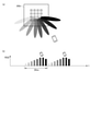
- FIG. 4 is a diagram showing an example of beamforming by the slave unit shown in FIG.
- FIG. 5 is a diagram showing an example of searching for a mobile station by the handset shown in FIG.
- FIG. 6 is a flowchart for explaining the processing of the master unit shown in FIG.
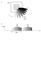
- FIG. 7 is a diagram showing an example of a high-speed search for a mobile station by the handset shown in FIG.
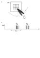
- FIG. 8 is a diagram showing an example of a low-speed search for a mobile station by the handset shown in FIG.
- FIG. 1 is a diagram showing a mobile communication system including a communication relay system.
- FIG. 2 is a diagram showing a configuration example of the master unit shown in FIG.
- FIG. 3 is a diagram showing a
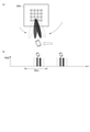
- FIG. 9 is a diagram showing an example of tracking search of a mobile station by the slave unit shown in FIG. 1.
- FIG. 10 is a diagram showing an example of tracking search of a mobile station by the slave unit shown in FIG. 1.
- FIG. 11 is a diagram showing an example of searching for a mobile station by the handset shown in FIG.
- FIG. 12 is a diagram showing an example of searching for a mobile station by the handset shown in FIG.
- FIG. 13 is a diagram showing an example of searching for a mobile station by the handset shown in FIG.
- FIG. 1 shows a part of a 5th generation mobile communication system, so-called 5G.
- This mobile communication system includes a 5G core network (5th Generation Core network) 5GC and a radio access network NR (New radio).
- the example of FIG. 1 shows a case where the radio access network NR includes a communication relay system.
- the 5G core network 5GC controls the radio access network NR, bundles traffic, and exchanges with an external network (Internet IN, external telephone network EN, etc.), and includes a core device C as the center thereof.
- the core device C performs, for example, authentication / security management, session management, policy control, packet transfer, and the like.
- the radio access network NR includes a plurality of base station devices (for example, gNB (gNodeB) 1 and gNB 2 in FIG. 1).
- the base station devices gNB1 and gNB2 are controlled by the core device C, and each form a wireless communication area (so-called cell) capable of communicating with the mobile station UE (User Equipment).
- the base station device gNB1 wirelessly communicates with the mobile station UE through the antenna device AN provided on the roof of the building or a dedicated steel tower, and connects the mobile station UE to the 5G core network 5GC through the core device C. .. Further, the base station device gNB1 performs beamforming by massive MIMO (Massive MIMO) that controls the phase of signals in a large number of antenna elements on the antenna device AN, and contributes to an increase in communication capacity and the like.
- massive MIMO massive MIMO
- the base station device gNB2 has the same function as the base station device gNB1, but wirelessly communicates with the mobile station UE through the distributed antenna system DAS instead of the antenna device AN, and the mobile station UE communicates wirelessly with the mobile station UE through the core device C to the 5G core network NW. Connect to.
- the distributed antenna system DAS is an example of a communication relay system, and is an example of a special place (for example, the inside of a building, an underground street, or other structure, a depopulated area or an overcrowded area, an area where it is difficult or restricted to construct a steel tower, an event venue. It is used to form a relatively small wireless communication area compared to the antenna device AN in an emergency location of the antenna device AN, etc.), and as shown in FIG. 1, the master unit MU (Master Unit). ), Slave units RU (RemoteUnit) 1 to RU3, and antennas AN1 to AN3.
- MU Master Unit
- Slave units RU RemoteUnit
- the master unit MU controls each part of the distributed antenna system DAS in an integrated manner, and is a base station apparatus for a mobile station UE connected via an antenna (AN1 to AN3) and a slave unit (RU1 to RU3). It plays a role as a communication relay device that enables communication with gNB2.
- the master unit MU When the master unit MU is connected to the slave units RU1 to RU3 by an optical communication line, the master unit MU may also be generally referred to as an optical repeater.
- the antennas AN1 to AN3 are connected to the corresponding slave units RU1 to RU3 on a one-to-one basis, and each consists of a large number of antenna elements, and the directivity is controlled (beamforming) by adjusting the phase of the transmitted RF signal and / or the received RF signal. ) Corresponds to Massive MIMO.
- each antenna AN1 to AN3 will be described as performing beamforming for forming a maximum of four beams in an arbitrary direction at the same time, and will be described in detail later.
- the MU will also be described as processing (relaying) up to four streams at the same time corresponding to the above four beams.
- the maximum number is not limited to 4, but may be 3 or less or 5 or more. Further, the number of beams formed by each of the antennas AN1 to AN3 is not fixed, and may be dynamically changed by varying the number of antenna elements to be used.
- the slave units RU1 to RU3 are connected to the corresponding antennas AN1 to AN3 on a one-to-one basis, and can be connected to the master unit MU via an optical communication line.
- the slave units RU1 to RU3 are directly connected to the master unit MU, respectively.
- a method (not shown) is also conceivable.
- the slave units RU1 to RU3 can perform beamforming by phase adjustment for the corresponding antennas AN1 to AN3, respectively, and detect the direction in which the mobile station UE exists by measuring the reception intensity and beamforming. It can (search) and follow the moving mobile station UE for communication.
- the slave units RU1 to RU3 perform phase adjustment (beamforming) for each RF signal obtained by the corresponding antennas AN1 to AN3 for the uplink.
- received RF signals corresponding to a maximum of four beams are obtained from each of the antennas AN1 to AN3.
- the slave units RU1 to RU3 down-convert the received RF signals corresponding to each beam and simultaneously demodulate the received RF signals corresponding to a maximum of four beams into four received signals. Then, the slave units RU1 to RU3 serially bundle the demodulated received signals, convert the electric signal into an optical signal (modulate the optical carrier wave), and transmit the demodulated signal to the master unit MU through the optical communication line.
- the stream included in the received signal is referred to as a UL stream signal.
- the slave units RU1 to RU3 convert the optical signal transmitted from the master unit MU through the optical communication line into an electric signal, and simultaneously correspond to a maximum of four streams (hereinafter, DL). Demodulate to a stream signal).
- the slave units RU1 to RU3 generate a transmission RF signal whose carrier wave is modulated by using the DL stream signal, output the transmission RF signal to the connected antennas AN1 to AN3, and radiate it into space.
- the slave units RU1 to RU3 can perform beamforming to form a maximum of four beams at the same time, and form a beam for each DL stream signal for transmission. That is, when four DL stream signals are obtained by demodulation, four beams are formed, and each beam transmits one DL stream signal.
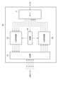
- FIG. 2 shows a configuration example of the master unit MU. That is, the master unit MU includes a port P, a control unit 100, a transmission unit 110, a UL (UpLink) signal processing unit 120, and a DL (DownLink) signal processing unit 130.
- the master unit MU includes a port P, a control unit 100, a transmission unit 110, a UL (UpLink) signal processing unit 120, and a DL (DownLink) signal processing unit 130.
- the port P accommodates an optical communication line, can be connected to the slave units RU1 to RU3 via the optical communication line, and is connected to the UL signal processing unit 120 and the DL signal processing unit 130.
- it is the slave unit RU1 that is physically directly connected via the optical communication line, but the optical communication line is connected to the optical communication between the slave units RU2 and RU3. Since the signals are also multiplexed, the port P is substantially connected to the slave units RU2 and RU3, and can transmit and receive optical signals to and from any of the slave units RU1 to RU3.
- the port P demultiplexes the optical signal sent from the slave unit RU1, separates it into a plurality of optical signals, converts each optical signal into an electric signal and demodulates it, and obtains a plurality of telecommunications signals. ..
- the plurality of telecommunication signals are received signals corresponding to the respective beams (or UL stream signals) of the slave units RU1 to RU3, and are output to the UL signal processing unit 120 in parallel.
- the port P also functions as an information detection unit that acquires information sent from the slave units RU1 to RU3 from each received signal, monitors each demodulated received signal, and is a mobile station UE included in the received signal. It detects a communication start request (PRACH) from and detects a stream ID assigned to each received signal (UL stream signal). Further, the port P functions as a position detection unit, and detects the presence of the mobile station UE located in the cover area formed by the slave units RU1 to RU3 from the above detection results and the like. These detection results are notified to the control unit 100.
- PRACH communication start request
- UL stream signal UL stream signal
- the port P adds the identification information of the slave units RU1 to RU3 to be the input DL stream signal, converts the electric signal into an optical signal (modulation of the optical carrier wave), and converts these optical signals. It is multiplexed and transmitted to the slave units RU1 to RU3 through the optical communication line.
- the transmission unit 110 accommodates a communication line connected to the base station device gNB2, and communicates with the base station device gNB2 through this communication line. Specifically, regarding the uplink, the transmission unit 110 transmits UL signals (up to four at the same time) input from the UL signal processing unit 120 to the base station device gNB2. On the other hand, regarding the downlink, the transmission unit 110 receives the DL stream signals (up to four at the same time) transmitted from the base station apparatus gNB2 through the communication line, and outputs them to the DL signal processing unit 130.
- the UL signal processing unit 120 performs signal addition processing for adding the received signals of each beam input from the port P under the control of the control unit 100, and outputs the UL signal to the transmission unit 110.
- the DL signal processing unit 130 performs multiplexing processing for multiplexing the DL stream signal input from the transmission unit 110 and outputting it to the port P under the control of the control unit 100.
- the control unit 100 is a control center that collectively controls each unit of the master unit MU, and executes a memory (not shown) for storing a control program and control data, and processing based on the control program and the control data. It is equipped with a processor (not shown), which realizes various control functions.
- the control program may be provided by a storage medium other than the memory.
- control unit 100 performs communication relay control between the mobile station UE and the base station device gNB2 through the slave units RU1 to RU3, as well as the detection result notified from the port P and the base station. Based on the DL stream signal transmitted from the device gNB2, stream allocation control and handover control are performed for the slave units RU1 to RU3.
- the slave unit information including the capabilities of the slave units RU1 to RU3 (the number of streams that can be supported), the number of streams currently allocated, and the mobile station information including the position information of the mobile station UE are stored and stored. It manages (updates) and allocates streams to the slave units RU1 to RU3 based on the slave unit information and mobile station information.
- the necessity of changing the slave units RU1 to RU3 to be communicated with the mobile station UE is determined based on the detection result notified from the port P, and each slave unit is determined based on this determination result. Instruct RU1 to RU3 and the mobile station UE to perform handover between slave units.
- the signal strength of the received signal from the mobile station UE notified from each RU1 to RU3 is compared, and the signal strength notified from the slave unit during communication is set in advance.
- the signal strength of the same mobile station UE notified from another slave unit is lower than the threshold value of 1 and exceeds the second threshold value, the handover to the other slave unit is performed for both slave units.
- the conditions for determining the necessity of handover are not limited to this example, and various conditions may be considered depending on the installation environment and the like, and they may be applied.
- slave unit RUN the description will be described as “slave unit RUN”.
- slave unit RUN the description is common to all of the slave units RU1 to RU3. That is, in the following description, "n” can be read as any of 1 to 3.
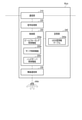
- FIG. 3 shows a configuration example of the slave units RUN (RU1 to RU3). That is, the slave unit RUN includes a control unit 200, a communication unit 210, a signal processing unit 220, a wireless communication unit 230, a storage unit 240, and an antenna ANn.
- the slave unit RUN includes a control unit 200, a communication unit 210, a signal processing unit 220, a wireless communication unit 230, a storage unit 240, and an antenna ANn.
- the communication unit 210 transmits / receives an optical communication signal through an optical communication line, includes at least two ports to accommodate, amplifies the optical communication signal received through the optical communication line accommodated in one port, and the other. It has a function as an optical communication repeater for transmitting through an optical communication line accommodated in the port of No. 1 and a function as a modulator / demodulator for mutual conversion between an optical signal and an electric signal.
- the modulator / demodulator has an optical / electrical conversion function that receives an optical signal through an optical communication line and performs optical / electrical conversion to obtain an electrical communication signal (DL stream signal), and inputs from a signal processing unit 220 described later. It has an electric / optical conversion function that converts the generated electrical communication signal (UL stream signal) into an optical communication signal and transmits it through an optical communication line.
- the signal processing unit 220 communicates with the base station device gNB2 according to a predetermined communication protocol.
- the communication signal obtained by the communication unit 210 is demodulated and decoded, the DL stream signal addressed to the slave unit RUN is detected, and the DL stream signal is output to the control unit 200.
- a signal addressed to the base station device gNB2 given from the control unit 200 is used for carrier wave modulation to generate a UL stream signal and output it to the communication unit 210.
- the wireless communication unit 230 performs wireless communication with the mobile station UE through the antenna ANn, and adopts a 5G-compliant method as the wireless access method. Therefore, even when the mobile station UE communicates through the distributed antenna system DAS, the mobile station UE can perform wireless communication by the same wireless access method as when communicating with the base station apparatus gNB1 through the antenna AN shown in FIG.
- the wireless communication unit 230 performs beamforming by massive MIMO that controls the phase of signals (transmitted RF signal and / or received RF signal) in a large number of antenna elements on the antenna ANn according to the instruction of the control unit 200. Further, the wireless communication unit 230 measures the received signal strength (for example, RSSI) from the mobile station UE, associates the measurement result with the identification information of the mobile station UE, and notifies the control unit 200.
- the received signal strength for example, RSSI
- the control unit 200 is a control center that collectively controls each unit of the slave unit RUN, and is based on a work memory (not shown), a control program read from the storage unit 240 described later into the work memory, and control data. It is equipped with a processor (not shown) that executes processing, and realizes various control functions by these.
- the control unit 200 has a communication control function for connecting a mobile station UE wirelessly connected to the slave unit RUN to the 5G core network 5GC via the master unit MU and the base station device gNB2. At least, it includes a beamforming control function 200a, a search control function 200b, and a handover control function 200c, and also has a processing function that integrates and executes these functions.
- the beamforming control function 200a controls massive MIMO by the wireless communication unit 230, and performs beamforming according to a predetermined algorithm according to the number of streams assigned to the mobile station UE and the like.
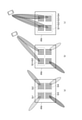
- FIG. 4 shows an example of beamforming.
- the antenna ANn is divided into four groups Gr1 to Gr4 so that a large number of antenna elements correspond to four streams, for example, as shown in FIG. 4A, and each group has an arbitrary direction.
- the directivity can be controlled.
- a stream by group Gr1 and a stream by group Gr2. Performs beamforming to direct the mobile station UE in the direction in which it exists.
- each stream by the groups Gr1 to Gr4 is assigned. Beamforming is performed in the direction in which the mobile station UE exists.
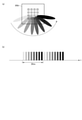
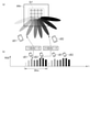
- the search control function 200b controls the wireless communication unit 230 to search for and estimate (detect) the direction and distance in which the mobile station UE exists. Specifically, the search control function 200b controls the massive MIMO by the wireless communication unit 230, and repeats the direction in which the beam is directed in an arbitrary range every 20 ms, for example, as shown in FIG. 5 (a). Sweeping is performed, and during this period, the received signal strength sequentially detected by the wireless communication unit 230 is monitored to detect the direction and distance in which the mobile station UE is present.
- FIG. 5B shows the timing of each beam shown in FIG. 5A, and the matching of shades in both figures shows the correspondence relationship.
- the handover control function 200c is a control function that realizes the handover of the mobile station UE between the slave units RU1 and RU3 in cooperation with the master unit MU. More specifically, the handover control function 200c notifies the master unit MU of the received signal strength sequentially detected by the wireless communication unit 230, and moves during communication according to an instruction from the master unit MU (handover control function). The communication with the station UE is terminated (for example, when moving out of the coverage area), or the communication with the mobile station UE is newly started (for example, when moving in the coverage area).
- the storage unit 240 stores the control program and control data used by the control unit 200, and also stores the UE position information table 240a.
- the control program and the control data are installed in advance at the time of manufacture, installed or updated through an external interface (not shown) at the time of setting the work order, or communicate with a server on the 5G core network 5GC such as the core device C. It will be installed and updated.
- the UE position information table 240a is a data table that records the position information of the mobile station UE existing in the cover area of the slave unit RUN, and is associated with information such as identification information, position information, and update date and time of the mobile station UE. Be remembered.
- the position information for example, a combination of the above-mentioned identification information of the antenna element groups Gr1 to Gr4, the directivity information directed by the beam, the estimated distance information, and the like can be considered, but the information is limited to these. is not it.
- FIG. 6 is a flowchart for explaining the control flow of the control unit 200 of the slave unit RUN.
- control unit 200 executes several control flows in parallel, one of which is the control flow shown in FIG.
- the control flow shown in FIG. 6 is repeatedly executed until the operation of the slave unit RUN is stopped or a stop command is issued from the master unit MU or the like.
- step 601 the control unit 200 starts or restarts the timer T, sets a value meaning OFF in the parameter of the timeout flag F stored in the work memory, and proceeds to step 602. That is, the control unit 200 starts or restarts the time count by the timer T from the time when the process shifts to step 601.
- step 602 the control unit 200 determines whether or not a new stream has been assigned to the mobile station UE from the master unit MU.
- the new stream referred to here is a stream for newly performing communication in response to a request from the master unit MU.
- the process proceeds to step 606, while if a new stream has not been assigned, the process proceeds to step 603.
- step 603 the control unit 200 determines whether or not a new communication start request has been generated from the mobile station UE.
- the request for starting new communication here means a request for performing new communication in response to a request from the mobile station UE.
- the process proceeds to step 606, while if a new communication start request is not generated, the process proceeds to step 604.
- step 604 the control unit 200 checks the timer T activated in step 601 and determines whether or not the preset time t has elapsed from step 601. Here, if the time t has elapsed, the process proceeds to step 605, while if the time has not elapsed, the process proceeds to step 602 again.
- step 605 the control unit 200 sets a value meaning ON in the parameter of the timeout flag F described above, and proceeds to step 607.
- the time-out flag F indicates that the processing of the subsequent steps 607 to 609 was executed triggered by the time-out in step 604.
- control unit 200 refers to the UE position information table 240a stored in the storage unit 240, compares the update date and time included in this table with the current time, and determines whether or not a preset time has elapsed. do.
- step 607 if there is no information in the UE position information table 240a or the preset time has elapsed, the process proceeds to step 607. On the other hand, if the preset time has not elapsed, the process proceeds to step 611.
- step 607 search for the mobile station UE. I do.
- the process proceeds to step 611 to allocate the stream.
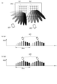
- the control unit 200 uses the search control function 200b to execute a high-speed search for detecting the direction in which the mobile station UE exists, and proceeds to step 608. Specifically, the control unit 200 controls the massive MIMO by the wireless communication unit 230 to reduce the variable range of the direction in which the beam is directed (for example, the horizontal direction), for example, as shown in FIG. 7A.
- the temperature is set to 120 °, and as shown in FIG. 7B, the sweep is repeated every 20 ms, and during this period, the received signal strength sequentially detected by the wireless communication unit 230 is monitored, and the identification information of the mobile station UE and the mobile station are monitored. Detects the direction and distance in which the UE is located.
- FIG. 7 (b) shows the received signal intensities corresponding to each beam shown in FIG. 7 (a), and the matching of the shades in both figures shows the correspondence relationship.
- this high-speed search is independently performed for each of the four groups Gr1 to Gr4 of the antenna elements on the antenna ANn.
- the orientations searched by each group Gr1 to Gr4 are arbitrarily set by the worker at the time of setting the work order, or are cumulatively stored in the storage unit 240 based on the statistical data and learning data of the position information of the mobile station UE.
- the search control function 200b may be set by itself or may be updated by reviewing the setting.
- the control unit 200 uses the search control function 200b to execute a low-speed search for detecting the direction in which the mobile station UE exists with higher accuracy, and proceeds to step 609. Specifically, the control unit 200 controls the massive MIMO by the wireless communication unit 230 to set a variable range of the direction in which the beam is directed (for example, the horizontal direction), for example, as shown in FIG. 8A. It is set to about 90 °, which is narrower than about 120 ° at the time of high-speed search, and is repeatedly swept every 20 ms as shown in FIG. 8 (b). The identification information of the mobile station UE and the direction and distance in which the mobile station UE exists are detected by monitoring at the same frequency as. Similarly to FIG. 7, FIG. 8 (b) shows the received signal intensities corresponding to each beam shown in FIG. 8 (a), and the matching of the shades in both figures shows the correspondence relationship. There is.
- this low-speed search is independently performed for each of the four groups Gr1 to Gr4 of the antenna elements on the antenna ANn.
- the orientation searched by each group Gr1 to Gr4 is set to be centered on the direction detected by the high-speed search in step 607.
- the search control function 200b limits the range of the search direction by the worker at the time of setting the work order, or based on the statistical data and learning data of the position information of the mobile station UE cumulatively stored in the storage unit 240. You may limit yourself or review the scope of the limitation.
- step 608 the parameter of the timeout flag F stored in the work memory is referred to, and if a value meaning ON is set, the low-speed search of step 608 is skipped and step 609 is performed. You may want to move to. That is, if a timeout occurs, a search with higher accuracy may be omitted.
- step 609 the control unit 200 associates the identification information of the mobile station UE detected in step 608 with the information of the existing direction and distance (position information) and the time of detection (update date and time), and the UE position information. Recording is performed on the table 240a, and the process proceeds to step 610.
- the information of the same mobile station exists in the UE position information table 240a, the information may be overwritten and saved, or the information for a certain period (a certain number of times) may be accumulated as a log. You may try to save it. This log can be used by the control unit 200 as the above-mentioned learning data.
- step 610 the control unit 200 refers to the parameter of the timeout flag F stored in the work memory, and determines whether or not a value meaning ON is set.
- the process proceeds to step 601.
- a value meaning OFF is set, the process proceeds to step 611.
- step 611 the control unit 200 allocates a stream to the mobile station UE, and proceeds to step 612. Specifically, when it is determined in step 602 that a new stream has been assigned by the master unit MU, the control unit 200 transfers the ID of the stream notified by the master unit MU to the mobile station UE. On the other hand, when a new communication start request is generated from the mobile station UE in step 603, the ID of a free stream is assigned to the mobile station UE. It is assumed that the control unit 200 is periodically notified in advance of the ID of the vacant stream from the master unit MU.
- step 612 the control unit 200 controls the massive MIMO by the wireless communication unit 230 by using the beamforming control function 200a for the stream assigned to the mobile station UE in step 611, and the beam according to a predetermined algorithm. Forming is performed, and the process proceeds to step 613.
- control unit 200 refers to the UE position information table 240a, and the mobile station UE uses the identification information of the mobile station UE to which the stream is assigned in step 611 and the position information associated with the identification information. Form a beam oriented in the direction it exists.
- step 613 the control unit 200 controls the wireless communication unit 230 to establish a wireless communication link with the mobile station UE to which the stream is assigned in step 611, and controls the signal processing unit 220 to control the mobile station UE.
- a communication link for is established with the core device C, the mobile station UE is connected to the core device C through these links, and the process proceeds to step 614. After that, communication is started between the mobile station UE and the core device C via the stream assigned in step 611.
- step 614 the control unit 200 uses the search control function 200b to perform a low-speed search for tracking the direction in which the mobile station UE exists in order to maintain the wireless communication link established in step 613, and steps 615. Move to.
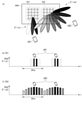
- control unit 200 controls the massive MIMO by the wireless communication unit 230 to set a variable range of the direction in which the beam is directed (for example, the horizontal direction), for example, as shown in FIG. 9A. It is set to a traceable range (about 45 ° in the example of FIG. 9A), which is narrower than about 90 ° at the time of low-speed search in step 608.
- the control unit 200 repeatedly sweeps every 20 ms, and during this period, the radio communication unit 230 monitors the received signal strength sequentially detected, and the identification information of the mobile station UE and the mobile station. Detects the direction in which the UE is located.
- 9 (b) shows the received signal intensity corresponding to each beam shown in FIG. 9 (a), similarly to FIG. 8, and shows the shades of the shades in FIGS. 9 (a) and 9 (b). The match indicates the correspondence.
- the variable range may be changed based on the data learned by the control unit 200 about the movement of the mobile station UE. Further, the control unit 200 may estimate the distance between the slave unit RUN and the mobile station UE from the received signal strength and change the variable range. In this case, when the received signal strength is relatively high, the control unit 200 determines that the distance between the slave unit RUN and the mobile station UE is short, widens the variable range, and on the other hand, the received signal strength is relative. If it is too low, it is determined that the distance between the slave unit RUN and the mobile station UE is long, and the variable range is narrowed.
- step 615 the control unit 200 uses the beamforming control function 200a to perform beamforming to form a beam directed in the direction detected in step 614, and maintains the wireless communication link established in step 613. Move to 616.
- step 614 the control unit 200 estimates the moving direction of the mobile station UE, and in step 615, the control unit 200 performs beamforming to form a beam directed in the direction based on the estimation result of step 614. May be good. For example, as shown in FIG. 10A, when the mobile station UE moves, the control unit 200 determines the strength of the received signal of each beam, the magnitude relationship of the received signal strength in each direction, and the change thereof. The direction of movement can be estimated.
- step 616 the control unit 200 determines whether or not the communication started in step 613 has ended.
- the process is newly started from step 601.
- the process proceeds to step 614 to continue to maintain the wireless communication link. Continue beamforming.
- the directivity direction of the beam is changed for each of the slave units RU1 to RU3, and the direction and distance in which the mobile station UE exists are based on the signal strength received from the mobile station UE. Is detected. Therefore, according to the communication relay system having the above configuration, the slave units RU1 to RU3 can detect the position of the mobile station UE existing in each cover area.
- the slave units RU1 to RU3 direct the beam in a wide range direction to detect the position of the mobile station UE, and the beam is directed in a narrower direction than this high-speed search. A low-speed search that detects the position of the mobile station UE with higher accuracy is continuously performed. Therefore, according to the communication relay system having the above configuration, the slave units RU1 to RU3 can efficiently detect the position of the mobile station UE existing in each cover area.
- the slave units RU1 to RU3 change the directivity direction of the beam so as to track the mobile station UE. Therefore, according to the communication relay system having the above configuration, the slave units RU1 to RU3 can stably communicate with the mobile station UEs existing in the respective cover areas, and can perform high quality communication.
- the slave units RU1 to RU3 divide the antenna elements on the antennas AN1 to AN3 of each into four groups Gr1 to Gr4, and direct the beam independently for each group Gr1 to Gr4. The direction is changed so that the mobile station UE is tracked.
- FIG. 11A even if a plurality of mobile stations UE1 and UE2 are present in substantially the same direction with respect to the antenna ANn, the two groups Gr1 , Gr2 can search for the direction set for each.
- FIGS. 11 (b) and 11 (c) show the received signal intensities corresponding to each beam shown in FIG. 11 (a), and the matching of the shades in both figures shows the correspondence relationship. There is.
- the group Gr1 tracks the mobile station UE1 by step 614 of FIG.
- the group Gr2 can perform a high-speed search for the mobile station UE2 by step 607 of FIG. 6 while performing a low-speed search for the above.
- FIGS. 12 (b) and 12 (c) show the received signal intensities corresponding to each beam shown in FIG. 12 (a), and the matching of the shades in both figures shows the correspondence relationship. There is.
- the present invention is not limited to the above embodiment as it is, and at the implementation stage, the components can be modified and embodied within a range that does not deviate from the gist thereof. Further, various inventions can be formed by appropriately combining a plurality of components disclosed in the above embodiments. Further, for example, a configuration in which some components are deleted from all the components shown in the embodiment can be considered. Further, the components described in different embodiments may be combined as appropriate.
- one group of antenna elements searches for one mobile station UE has been described as an example, but two or more mobile stations are described as one.
- the antenna group may be searched.
- the group Gr1 on the antenna ANn searches for two mobile stations UE1 and UE2.
- the control unit 200 detects the peak of the received signal strength to determine the number of mobile stations and their directions. Can be detected.
- FIG. 13 (b) shows the received signal intensities corresponding to each beam shown in FIG. 13 (a), and the matching of the shades in both figures shows the correspondence relationship.
- the beam is directed for the same antenna group as illustrated in FIGS. 7, 8, and 9.
- the case of controlling the range of directions has been described as an example, but the present invention is not limited to this.
- the antenna groups used may be different for some or all of them. That is, for example, the group Gr1 is used in the high-speed search in step 607 and the low-speed search in step 608, and the group Gr2 is used in the low-speed search in step 614.
- the high speed search in step 607 uses the group Gr1 and the low speed search in step 614 and the low speed search in step 608 use the group Gr2.
- the high speed search in step 607 and the low speed search in step 614 use group Gr1 and the low speed search in step 608 uses group Gr2.
- the high speed search in step 607 uses group Gr1, the low speed search in step 608 uses group Gr2, and the low speed search in step 614 uses group Gr3.
Landscapes
- Engineering & Computer Science (AREA)
- Computer Networks & Wireless Communication (AREA)
- Signal Processing (AREA)
- Physics & Mathematics (AREA)
- General Physics & Mathematics (AREA)
- Radar, Positioning & Navigation (AREA)
- Remote Sensing (AREA)
- Mobile Radio Communication Systems (AREA)
- Radio Relay Systems (AREA)
Abstract
Description
図1は、第5世代移動通信システム、いわゆる5Gの一部を示すものである。この移動通信システムは、5Gコアネットワーク(5th Generation Core network)5GCと、無線アクセスネットワークNR(New radio)を備える。図1の例では、無線アクセスネットワークNRに、通信中継システムを含む場合を示している。
DL信号処理部130は、制御部100の制御にしたがって、伝送部110から入力されるDLストリーム信号を多重化してポートPに出力する多重化処理を施す。
そしてまた無線通信部230は、移動局UEからの受信信号強度(例えば、RSSI)を計測し、この計測結果を移動局UEの識別情報に対応付けて、制御部200に通知する。
具体的には、制御部200は、無線通信部230によるマッシブMIMOを制御して、例えば、図7(a)に示すように、ビームの指向する方向(例えば、水平方向)の可変範囲を約120°に設定し、図7(b)に示すように20msごとに繰り返して掃引し、この間、無線通信部230が逐次検出する受信信号強度を監視して、移動局UEの識別情報と移動局UEが存在する方向や距離を検出する。なお、図7(b)は、図7(a)に示した各ビームに対応する受信信号強度を示したものであり、両図における濃淡の一致が対応関係を示している。
具体的には、制御部200は、無線通信部230によるマッシブMIMOを制御して、例えば、図8(a)に示すように、ビームの指向する方向(例えば、水平方向)の可変範囲を、高速サーチ時の約120°よりも狭い約90°に設定し、図8(b)に示すように20msごとに繰り返して掃引し、この間、無線通信部230が逐次検出する受信信号強度を高速サーチと同じ頻度で監視して、移動局UEの識別情報と移動局UEが存在する方向や距離を検出する。なお、図7と同様に、図8(b)は、図8(a)に示した各ビームに対応する受信信号強度を示したものであり、両図における濃淡の一致が対応関係を示している。
したがって、上記構成の通信中継システムによれば、子機RU1~RU3がそれぞれのカバーエリアに存在する移動局UEの位置を検出することができる。
したがって、上記構成の通信中継システムによれば、子機RU1~RU3がそれぞれのカバーエリアに存在する移動局UEの位置を効率的に検出することができる。
したがって、上記構成の通信中継システムによれば、子機RU1~RU3がそれぞれのカバーエリアに存在する移動局UEと安定した通信が行え、高い品質の通信を行うことができる。
なお、図11(b)および図11(c)は、図11(a)に示した各ビームに対応する受信信号強度を示したものであり、両図における濃淡の一致が対応関係を示している。
なお、図12(b)および図12(c)は、図12(a)に示した各ビームに対応する受信信号強度を示したものであり、両図における濃淡の一致が対応関係を示している。
なお、図13(b)は、図13(a)に示した各ビームに対応する受信信号強度を示したものであり、両図における濃淡の一致が対応関係を示している。
Claims (6)
- ネットワークに接続される基地局と、移動局との間の通信を中継する通信中継装置において、
任意の方向に電波のビームを形成するアンテナと、
前記アンテナが受信した信号強度を検出する信号強度検出部と、
前記アンテナが形成するビームの方向を第1の範囲で変化させ、前記信号強度検出部が検出した信号強度に基づいて、前記移動局が存在する方向を検出する第1のサーチ部と、
前記アンテナが形成するビームの方向を、前記第1のサーチ部が検出した方向を含み、かつ前記第1の範囲よりも狭い第2の範囲で変化させ、前記信号強度検出部が検出した信号強度に基づいて、前記移動局が存在する方向を検出する第2のサーチ部と、
を具備した通信中継装置。 - 前記アンテナは、多数のアンテナ素子を備え、このアンテナ素子を介する信号の位相調整により指向性が制御され、
前記第1のサーチ部は、前記信号の位相調整によって、前記アンテナが形成するビームの方向を第1の範囲で変化させ、
前記第2のサーチ部は、前記信号の位相調整によって、前記アンテナが形成するビームの方向を第2の範囲で変化させる、請求項1に記載の通信中継装置。 - 前記第1のサーチ部は、前記アンテナが備える多数のアンテナ素子のうちの一部のアンテナ素子を介する信号の位相調整によって、前記アンテナが形成するビームの方向を第1の範囲で変化させ、
前記第2のサーチ部は、前記アンテナが備える多数のアンテナ素子のうちの一部のアンテナ素子を介する信号の位相調整によって、前記アンテナが形成するビームの方向を第2の範囲で変化させる、請求項2に記載の通信中継装置。 - 前記第1のサーチ部は、前記アンテナが形成するビームの方向を第1の範囲で変化させ、前記信号強度検出部が検出した信号強度の変化に基づいて、前記移動局が存在する方向を検出するものであって、前記信号強度の変化のうちピークの無線信号を受信した方向を前記移動局が存在する方向として検出する、請求項1に記載の通信中継装置。
- さらに、前記アンテナが形成するビームの方向を、前記第2の範囲以下の第3の範囲で変化させて前記移動局から送信される無線信号を受信し、前記信号強度検出部が検出した信号強度に基づいて、前記移動局の移動を検出する第3のサーチ部を、
備える、請求項1に記載の通信中継装置。 - ネットワークに接続される基地局と、移動局との間の通信を中継する通信中継装置で用いられるコンピュータを、
任意の方向に電波のビームを形成するアンテナが受信した信号強度を検出する信号強度検出部と、
前記アンテナが形成するビームの方向を第1の範囲で変化させ、前記信号強度検出部が検出した信号強度に基づいて、前記移動局が存在する方向を検出する第1のサーチ部と、 前記アンテナが形成するビームの方向を、第1のサーチ部が検出した方向を含み、かつ前記第1の範囲よりも狭い第2の範囲で変化させ、前記信号強度検出部が検出した信号強度に基づいて、前記移動局が存在する方向を検出する第2のサーチ部と、
して機能させる、コンピュータプログラムを記憶した記憶媒体。
Priority Applications (2)
| Application Number | Priority Date | Filing Date | Title |
|---|---|---|---|
| GB2300505.1A GB2612475B (en) | 2020-07-14 | 2021-03-10 | Communication relay device and storage medium with computer program stored therein |
| US18/153,589 US12513536B2 (en) | 2020-07-14 | 2023-01-12 | Communication relay apparatus and storage medium storing computer program |
Applications Claiming Priority (2)
| Application Number | Priority Date | Filing Date | Title |
|---|---|---|---|
| JP2020-120727 | 2020-07-14 | ||
| JP2020120727A JP7618406B2 (ja) | 2020-07-14 | 2020-07-14 | 通信中継装置およびコンピュータプログラム |
Related Child Applications (1)
| Application Number | Title | Priority Date | Filing Date |
|---|---|---|---|
| US18/153,589 Continuation US12513536B2 (en) | 2020-07-14 | 2023-01-12 | Communication relay apparatus and storage medium storing computer program |
Publications (1)
| Publication Number | Publication Date |
|---|---|
| WO2022014092A1 true WO2022014092A1 (ja) | 2022-01-20 |
Family
ID=79554679
Family Applications (1)
| Application Number | Title | Priority Date | Filing Date |
|---|---|---|---|
| PCT/JP2021/009614 Ceased WO2022014092A1 (ja) | 2020-07-14 | 2021-03-10 | 通信中継装置およびコンピュータプログラムを記憶した記憶媒体 |
Country Status (4)
| Country | Link |
|---|---|
| US (1) | US12513536B2 (ja) |
| JP (1) | JP7618406B2 (ja) |
| GB (1) | GB2612475B (ja) |
| WO (1) | WO2022014092A1 (ja) |
Families Citing this family (1)
| Publication number | Priority date | Publication date | Assignee | Title |
|---|---|---|---|---|
| WO2023161980A1 (ja) * | 2022-02-22 | 2023-08-31 | 株式会社Nttドコモ | 無線基地局及び端末 |
Citations (3)
| Publication number | Priority date | Publication date | Assignee | Title |
|---|---|---|---|---|
| JP2003283404A (ja) * | 2002-03-20 | 2003-10-03 | Fujitsu Ltd | アレーアンテナ無線通信装置 |
| JP2017163501A (ja) * | 2016-03-11 | 2017-09-14 | 株式会社Nttドコモ | 基地局 |
| JP2019519956A (ja) * | 2016-05-05 | 2019-07-11 | 株式会社Nttドコモ | アップリンクパイロット及び分散されたユーザ近接検出に基づく基地局選択のメカニズム及び手順 |
Family Cites Families (7)
| Publication number | Priority date | Publication date | Assignee | Title |
|---|---|---|---|---|
| JP5039110B2 (ja) * | 2009-10-05 | 2012-10-03 | 株式会社エヌ・ティ・ティ・ドコモ | 基地局装置、移動局装置及び送信電力制御方法 |
| IT1398025B1 (it) * | 2010-02-12 | 2013-02-07 | Andrew Llc | Distributed antenna system for mimo communications. |
| JP6567438B2 (ja) | 2016-01-29 | 2019-08-28 | 株式会社東芝 | 通信中継システム、制御方法及びプログラム |
| US10153814B1 (en) * | 2017-06-13 | 2018-12-11 | Corning Incorporated | Massive multiple-input multiple-output (M-MIMO) wireless distribution system (WDS) and related methods for optimizing the M-MIMO WDS |
| WO2020076203A1 (en) * | 2018-10-12 | 2020-04-16 | Telefonaktiebolaget Lm Ericsson (Publ) | Methods and apparatuses for cell-free massive mimo communication |
| US11863359B1 (en) * | 2021-05-11 | 2024-01-02 | Amazon Technologies, Inc. | Subcarrier pre-equalization technology for frequency selective fading characteristics of wireless channels |
| US12261686B2 (en) * | 2022-03-03 | 2025-03-25 | Nec Corporation | Control apparatus, OAM mode-multiplexing transmitting apparatus, OAM mode-multiplexing receiving apparatus, control method, and non-transitory computer readable medium |
-
2020
- 2020-07-14 JP JP2020120727A patent/JP7618406B2/ja active Active
-
2021
- 2021-03-10 GB GB2300505.1A patent/GB2612475B/en active Active
- 2021-03-10 WO PCT/JP2021/009614 patent/WO2022014092A1/ja not_active Ceased
-
2023
- 2023-01-12 US US18/153,589 patent/US12513536B2/en active Active
Patent Citations (3)
| Publication number | Priority date | Publication date | Assignee | Title |
|---|---|---|---|---|
| JP2003283404A (ja) * | 2002-03-20 | 2003-10-03 | Fujitsu Ltd | アレーアンテナ無線通信装置 |
| JP2017163501A (ja) * | 2016-03-11 | 2017-09-14 | 株式会社Nttドコモ | 基地局 |
| JP2019519956A (ja) * | 2016-05-05 | 2019-07-11 | 株式会社Nttドコモ | アップリンクパイロット及び分散されたユーザ近接検出に基づく基地局選択のメカニズム及び手順 |
Also Published As
| Publication number | Publication date |
|---|---|
| US12513536B2 (en) | 2025-12-30 |
| GB2612475A (en) | 2023-05-03 |
| US20230171613A1 (en) | 2023-06-01 |
| GB2612475B (en) | 2024-09-18 |
| GB202300505D0 (en) | 2023-03-01 |
| JP2022017893A (ja) | 2022-01-26 |
| JP7618406B2 (ja) | 2025-01-21 |
Similar Documents
| Publication | Publication Date | Title |
|---|---|---|
| US11653286B2 (en) | Methods of mobile device based relay for coverage extension | |
| KR101174171B1 (ko) | 협동 릴레이를 이용한 무선 통신 네트워크를 위한 방법 및시스템 | |
| US8588614B2 (en) | Flexible distributed antenna system | |
| JP4950847B2 (ja) | 無線通信装置 | |
| US20020141375A1 (en) | Increasing link capacity via concurrent transmissions in centralized wireless LANs | |
| US20240107564A1 (en) | Communication relay system and radio device | |
| CN120264302A (zh) | 一种通信方法、系统及相关装置 | |
| US11510161B2 (en) | Wireless communication system and method | |
| WO2021022489A1 (zh) | 切换控制方法、装置、设备及存储介质 | |
| US20130322293A1 (en) | Apparatus for point-to-multi point communication in communication system and method thereof | |
| US20210266062A1 (en) | Radio communication system, radio communication method, and base station device | |
| EP1123589B1 (en) | Synchronization of terminals in a radio link system | |
| US12513536B2 (en) | Communication relay apparatus and storage medium storing computer program | |
| US10873955B2 (en) | Apparatus and method for allocating radio resources | |
| WO2024166765A1 (ja) | 通信中継システム、通信中継方法及びプログラム | |
| JP2025061804A (ja) | 通信中継装置およびプログラム | |
| KR101294504B1 (ko) | 무선 통신 네트워크에서 릴레이 접속을 지원하는 통신 방법 및 장치 | |
| US8670767B2 (en) | Radio base station apparatus configured to modify a softer handover enabled range | |
| KR20060095943A (ko) | 무선 자기조직화 통신망을 설정하기 위한 방법, 무선자기조직화 통신망의 송·수신기 및 기지국, 그리고 무선자기조직화 통신망 | |
| CN112738885B (zh) | 管理小基站的方法 | |
| RU2733784C1 (ru) | Высокоскоростная сеть с многократным переприемом и формированием диаграммы направленности антенны | |
| US20140219125A1 (en) | Base-station device and communication method | |
| KR101434526B1 (ko) | 무선통신 시스템의 릴레이 중계기에서 간섭 정보를 이용한공간 다중화 장치 및 방법 | |
| KR20130128028A (ko) | 통신 시스템에서 협업 통신을 수행하는 장치 및 방법 | |
| JP2004235839A (ja) | 固定無線アクセスシステム |
Legal Events
| Date | Code | Title | Description |
|---|---|---|---|
| 121 | Ep: the epo has been informed by wipo that ep was designated in this application |
Ref document number: 21843278 Country of ref document: EP Kind code of ref document: A1 |
|
| ENP | Entry into the national phase |
Ref document number: 202300505 Country of ref document: GB Kind code of ref document: A Free format text: PCT FILING DATE = 20210310 |
|
| WWE | Wipo information: entry into national phase |
Ref document number: 2300505.1 Country of ref document: GB |
|
| NENP | Non-entry into the national phase |
Ref country code: DE |
|
| WWP | Wipo information: published in national office |
Ref document number: 2300505.1 Country of ref document: GB |
|
| 122 | Ep: pct application non-entry in european phase |
Ref document number: 21843278 Country of ref document: EP Kind code of ref document: A1 |
|
| WWG | Wipo information: grant in national office |
Ref document number: 2300505.1 Country of ref document: GB |