WO2022014081A1 - 制御機器 - Google Patents
制御機器 Download PDFInfo
- Publication number
- WO2022014081A1 WO2022014081A1 PCT/JP2021/007065 JP2021007065W WO2022014081A1 WO 2022014081 A1 WO2022014081 A1 WO 2022014081A1 JP 2021007065 W JP2021007065 W JP 2021007065W WO 2022014081 A1 WO2022014081 A1 WO 2022014081A1
- Authority
- WO
- WIPO (PCT)
- Prior art keywords
- control
- notch
- housing
- control device
- knob member
- Prior art date
- Legal status (The legal status is an assumption and is not a legal conclusion. Google has not performed a legal analysis and makes no representation as to the accuracy of the status listed.)
- Ceased
Links
Images





Classifications
-
- G—PHYSICS
- G05—CONTROLLING; REGULATING
- G05G—CONTROL DEVICES OR SYSTEMS INSOFAR AS CHARACTERISED BY MECHANICAL FEATURES ONLY
- G05G1/00—Controlling members, e.g. knobs or handles; Assemblies or arrangements thereof; Indicating position of controlling members
- G05G1/08—Controlling members for hand actuation by rotary movement, e.g. hand wheels
- G05G1/10—Details, e.g. of discs, knobs, wheels or handles
Definitions
- This disclosure relates to control equipment.
- Patent Document 1 discloses a control device including an operation unit.
- the operation unit of the control device may be provided with a disk-shaped knob member for setting one control setting from a plurality of control settings.
- the knob member is rotatably provided with respect to the case of the control device, and has a triangular protrusion provided on the surface thereof. Numbers corresponding to each control setting are printed on the outer side of the knob member in the radial direction of the rotation axis, and the numbers facing the tips of the protrusions indicate the set control settings.
- control device is a thin control device that can be mounted inside the control panel using a DIN rail or directly inside the control panel, it is usually difficult to increase the size of the knob member. For this reason, for example, if there is a print misalignment in the numbers around the knob member, it may be difficult to visually recognize the numbers facing the tips of the protrusions, and it may be difficult to understand the set control settings.
- the object of the present disclosure is to provide a control device that makes it easy to confirm the set control settings.
- the control device of one example of the present disclosure is A control device having a plurality of control settings and operating based on one control setting set from the plurality of control settings.
- a setting unit provided in the housing and capable of setting the control setting is provided.
- the setting unit A knob member that is rotatably attached to the housing and can be rotated to set one of the control settings from among the plurality of control settings. It has a plurality of display units provided corresponding to each of the plurality of control settings and arranged at intervals outside the knob member in the housing in the radial direction with respect to the rotation axis thereof.
- a notch is provided at the radial outer end of the knob member, and the knob member is set on a virtual straight line passing through the notch and the rotation axis when viewed along the direction in which the rotation axis extends.
- a display unit corresponding to the control setting is arranged.
- a knob member that is rotatably attached to the housing and can set one control setting from a plurality of control settings by rotating the control device, and a knob member corresponding to each of the plurality of control settings are provided.
- the knob member in the housing has a plurality of display units arranged at intervals on the outer side in the radial direction with respect to the rotation axis.
- a notch is provided at the radial outer end of the knob member, and when viewed along the direction in which the rotation axis extends, a display corresponding to the control setting set on the virtual straight line passing through the notch and the rotation axis.
- the part is arranged. With such a configuration, it is possible to realize a control device that makes it easy to check the set control settings.
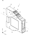
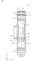
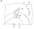
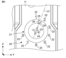
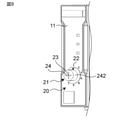
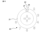
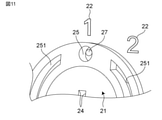
- the perspective view which shows the control apparatus of one Embodiment of this disclosure The front view of the control device of FIG. 1st enlarged front view of the control device of FIG. An enlarged perspective view of the control device of FIG. 1. A second enlarged front view of the control device of FIG. A third enlarged front view of the control device of FIG. The perspective view which shows the 1st modification of the control apparatus of FIG. The perspective view which shows the 2nd modification of the control device of FIG. The enlarged front view which shows the 3rd modification of the control device of FIG. The enlarged front view which shows the 4th modification of the control device of FIG. FIG. 3 is a perspective view showing a fifth modification of the control device of FIG. An enlarged front view showing a sixth modification of the control device of FIG. 1.
- the control device 1 of the embodiment of the present disclosure includes a housing 10 and a setting unit 20 provided in the housing 10.
- the control device 1 has a plurality of control settings and operates based on one control setting set from the plurality of control settings.
- the housing 10 has a substantially trapezoidal plate shape symmetrical with respect to the center line L1 extending along the first direction X, and has a pair of bottom surfaces 11 and 12 facing the first direction X.
- the setting unit 20 is arranged on one side.
- Each of the pair of bottom surfaces 11 and 12 has a substantially rectangular shape extending along a third direction Z intersecting (for example, orthogonal to) the first direction X and the second direction Y which is the plate thickness direction of the housing 10. They are different in size from each other.
- the setting unit 20 is arranged on the smaller bottom surface 11 as an example.
- Each of the pair of side surfaces 13 and 14 facing the third direction Z has a substantially rectangular shape extending along the first direction X.
- a plurality of terminal holes 15 into which electric wires and the like are inserted and connected are provided in the middle of one side surface 13 and one side surface 13.
- the setting unit 20 has a knob member 21 and a plurality of display units 22 provided corresponding to each of the plurality of control settings.
- the knob member 21 has a substantially disk shape and is rotatably attached to the housing 10.
- a cross groove 24 is provided in the center of the knob member 21.
- the knob member 21 is configured so that one control setting can be set from a plurality of control settings by rotating the knob member 21.
- a notch 25 is provided at the radial outer end of the knob member 21.
- the notch 25 has a rectangular shape extending in the radial direction from the radial outer end of the knob member 21, and is set on a virtual straight line L2 passing through the notch 25 and the rotation shaft 23. It is configured so that at least a part of the display unit 22 corresponding to the control setting is arranged.
- a straight line passing through the center of the rotation shaft 23 and the notch 25 in the circumferential direction is defined as a virtual straight line L2.
- tapered surfaces 26 are provided on the circumferential side surfaces of the rotating shaft 23 in the notch 25, respectively.
- the tapered surfaces 26 are configured to extend toward each other in the circumferential direction as the rotation shaft 23 extends away from the housing 10 (in other words, from the back to the front in the paper penetration direction of FIG. 3).
- the tapered surface 26 is provided on a part of the side surface of the notch 25, but the taper surface 26 is not limited to this.
- the tapered surface 26 may be provided on all the side surfaces of the notch 25.
- the display unit 22 is composed of eight numbers from “1” to "8", and is arranged at intervals outside the knob member 21 in the housing 10 in the radial direction with respect to the rotation axis 23. There is. In the present embodiment, the display unit 22 is arranged so that the interval between the numbers is substantially constant.
- Each number on the display unit 22 corresponds to a control setting that can be set, and a number located on the virtual straight line L2 indicates a set control setting.
- a plurality of electronic devices for example, an insulation resistance tester
- the control device 1 can control the electronic device corresponding to the “1”.
- the knob member 21 is rotated so that the number "2" is located on the virtual straight line L2 from this state, the control device 1 can control the electronic device corresponding to the "2".
- the setting unit 20 has an auxiliary display unit 27 provided in a portion of the housing 10 exposed from the notch 25.
- the auxiliary display unit 27 has a colored (for example, red) band shape and is intermittently provided at a position corresponding to a plurality of display units 22 around the rotation axis 23. That is, when the display unit 22 is located on the virtual straight line L2, the auxiliary display unit 27 is exposed from the notch 25 and the visibility of the notch 25 is improved, as shown in FIG. On the other hand, when the display unit 22 is not located on the virtual straight line L2, the auxiliary display unit 27 is not exposed from the notch 25 as shown in FIG.
- the auxiliary display unit 27 is provided in a part of the portion of the housing 10 exposed from the notch 25, but the present invention is not limited to this.
- the auxiliary display unit 27 may be provided on the entire portion of the housing 10 exposed from the notch 25.
- control device 1 According to the control device 1, the following effects can be exhibited.
- a knob member 21 that is rotatably attached to the housing 10 and can set one control setting from a plurality of control settings by rotating the control device 1 is provided corresponding to each of the plurality of control settings.
- the housing 10 has a plurality of display units 22 arranged at intervals on the outer side of the knob member 21 in the radial direction with respect to the rotation axis 23.
- a notch 25 is provided at the radial outer end of the knob member 21, and is set on a virtual straight line L2 passing through the notch 25 and the rotation shaft 23 when viewed along the direction in which the rotation shaft 23 extends.
- the display unit 22 corresponding to the control setting is arranged. With such a configuration, it is possible to realize the control device 1 in which it is easy to confirm the set control settings.
- the notch 25 has a quadrangular shape when viewed along the direction in which the rotation shaft 23 extends. With such a configuration, the visibility of the notch 25 can be improved. As a result, it is possible to realize the control device 1 in which it is easy to confirm the set control settings.
- the setting unit 20 is provided in the portion of the housing 10 exposed from the notch 25, and further has an auxiliary display unit 27 for improving the visibility of the notch 25. With such a configuration, it is possible to realize the control device 1 in which it is easy to confirm the set control settings.
- Auxiliary display units 27 are intermittently provided at positions corresponding to a plurality of display units 22 around the rotation axis 23. With such a configuration, it is possible to clarify whether or not the knob member 21 is located at a position where a predetermined control setting is set, and prevent erroneous operation.
- Knob members 21 are provided on the circumferential side surfaces of the rotary shaft 23 in the notch 25, and have tapered surfaces 26 that mutually expand in the circumferential direction as the rotary shaft 23 extends away from the housing 10. With such a configuration, for example, the viewing angle of the auxiliary display unit 27 can be widened to improve the visibility of the notch 25. As a result, it is possible to realize the control device 1 in which the set control settings are easy to understand.
- the control device 1 can also be configured as follows.
- the setting unit 20 can be provided at an arbitrary position on the housing 10. Further, the setting unit 20 can adopt an arbitrary configuration including the knob member 21 and the display unit 22.
- the knob member 21 is not limited to a substantially disk shape, and can adopt any configuration that can be rotated and control settings can be set.
- the knob member 21 may be configured to have a rectangular groove 241 into which a flat-blade screwdriver can be fitted instead of the cross groove 24.
- the knob member 21 may be configured to have a columnar protrusion 242 provided at the center thereof.
- the notch 25 is not limited to a square shape, and any shape can be adopted.
- the notch 25 may have a substantially circular shape.
- the notch 25 is not limited to the case where the knob member 21 penetrates in the direction in which the rotating shaft 23 extends, and may be formed by, for example, a bottomed recess. In this case, an auxiliary display unit can be provided on the bottom surface of the recess.
- the tapered surface 26 can be omitted.
- the auxiliary display unit 27 is not limited to a colored band shape, but can be configured with any shape, pattern, color, or a combination thereof.
- the auxiliary display unit 27 may have a colored substantially triangular shape.
- it may be a semicircular spherical protrusion.
- a groove 251 extending in the circumferential direction is provided at the outer end of the knob member 21, and an operation feeling (that is, a click feeling) is formed when the auxiliary display unit 27 moves between the notch 25 and the groove 251.
- the display unit 22 may be configured by a circular mark
- the auxiliary display unit 27 may be configured by a number.
- the control device 1 of the first aspect of the present disclosure is A control device 1 having a plurality of control settings and operating based on one control setting set from the plurality of control settings.
- Housing 10 and A setting unit 20 provided in the housing 10 and capable of setting the control setting is provided.
- the setting unit 20 A knob member 21 that is rotatably attached to the housing 10 and can be rotated to set one of the control settings from among the plurality of control settings. It has a plurality of display units 22 which are provided corresponding to each of the plurality of control settings and are arranged at intervals on the outer side in the radial direction of the knob member 21 of the knob member 21 in the housing 10.
- a notch is provided at the radial outer end of the knob member 21, and when viewed along the direction in which the rotation shaft 23 extends, the knob member 21 is set on a virtual straight line passing through the notch 25 and the rotation shaft 23.
- the display unit 22 corresponding to the control setting is arranged.
- the control device 1 of the second aspect of the present disclosure is
- the notch 25 has a quadrangular shape when viewed along the direction in which the rotating shaft 23 extends.
- the control device 1 of the third aspect of the present disclosure is The setting unit 20 It further has an auxiliary display unit 27 provided in the portion of the housing 10 exposed from the notch 25 and improving the visibility of the notch 25.
- the control device 1 of the fourth aspect of the present disclosure is The auxiliary display unit 27 It is intermittently provided at a position corresponding to the plurality of display units 22 around the rotation shaft 23.
- the control device 1 of the fifth aspect of the present disclosure is The knob member 21
- Each of the notches 25 is provided on the side surface of the rotating shaft 23 in the circumferential direction, and has tapered surfaces 26 that extend to each other in the circumferential direction as the rotating shaft 23 extends away from the housing 10.
- control equipment of the present disclosure can be applied to, for example, an insulation resistance tester, a timer relay and a voltage protection relay.
- Control equipment 10 Housing 11, 12 Bottom surface 13, 14 Side surface 15 Terminal hole 20
- Setting unit 21 Knob member 22
- Display unit 23 Rotating shaft 24, 241 Groove 242 Protrusion 25
- Notch 26 Tapered surface 27 Auxiliary display unit
Landscapes
- Physics & Mathematics (AREA)
- General Physics & Mathematics (AREA)
- Engineering & Computer Science (AREA)
- Automation & Control Theory (AREA)
- Mechanical Control Devices (AREA)
Abstract
制御機器が、ハウジングと、ハウジングに設けられた設定部とを備える。設定部が、ハウジングに回転可能に取り付けられ回転させることで複数の制御設定の中から1つの制御設定を設定可能なツマミ部材と、複数の制御設定の各々に対応して設けられハウジングにおけるツマミ部材のその回転軸に対する径方向の外側に間隔を空けて配置された複数の表示部とを有する。ツマミ部材の径方向の外端には切欠が設けられ、回転軸が延びる方向に沿って見たときに、切欠と回転軸とを通る仮想直線上に、設定されている制御設定に対応する表示部が配置される。
Description
本開示は、制御機器に関する。
特許文献1には、操作部を備えた制御機器が開示されている。
ところで、前記制御機器の操作部には、複数の制御設定の中から1つの制御設定を設定するための円板形状のツマミ部材が設けられる場合がある。ツマミ部材は、制御機器のケースに対して回転可能に設けられ、その表面に設けられた三角形状の突起を有している。ツマミ部材のその回転軸の径方向の外側には、各制御設定に対応する数字が印刷され、突起の先端に対向する数字によって、設定されている制御設定が示される。
前記制御機器は、制御盤内にDINレールを用いて、または直接、制御盤の内側に取り付けられる薄型の制御機器であるため、通常、ツマミ部材を大きくすることが難しい。このため、例えば、ツマミ部材の周囲の数字に印刷ずれがあると、突起の先端に対向する数字が視認し難くなり、設定されている制御設定が分かり難くなる場合がある。
本開示は、設定されている制御設定を確認し易い制御機器を提供することを課題とする。
本開示の一例の制御機器は、
複数の制御設定を有し、複数の前記制御設定の中から設定された1つの前記制御設定に基づいて動作する制御機器であって、
ハウジングと、
前記ハウジングに設けられ、前記制御設定を設定可能な設定部と
を備え、
前記設定部が、
前記ハウジングに回転可能に取り付けられ、回転させることで複数の前記制御設定の中から1つの前記制御設定を設定可能なツマミ部材と、
複数の前記制御設定の各々に対応して設けられ、前記ハウジングにおける前記ツマミ部材のその回転軸に対する径方向の外側に間隔を空けて配置された複数の表示部と
を有し、
前記ツマミ部材の前記径方向の外端には切欠が設けられ、前記回転軸が延びる方向に沿って見たときに、前記切欠と前記回転軸とを通る仮想直線上に、設定されている前記制御設定に対応する表示部が配置される。
複数の制御設定を有し、複数の前記制御設定の中から設定された1つの前記制御設定に基づいて動作する制御機器であって、
ハウジングと、
前記ハウジングに設けられ、前記制御設定を設定可能な設定部と
を備え、
前記設定部が、
前記ハウジングに回転可能に取り付けられ、回転させることで複数の前記制御設定の中から1つの前記制御設定を設定可能なツマミ部材と、
複数の前記制御設定の各々に対応して設けられ、前記ハウジングにおける前記ツマミ部材のその回転軸に対する径方向の外側に間隔を空けて配置された複数の表示部と
を有し、
前記ツマミ部材の前記径方向の外端には切欠が設けられ、前記回転軸が延びる方向に沿って見たときに、前記切欠と前記回転軸とを通る仮想直線上に、設定されている前記制御設定に対応する表示部が配置される。
前記制御機器によれば、ハウジングに回転可能に取り付けられ、回転させることで複数の制御設定の中から1つの制御設定を設定可能なツマミ部材と、複数の制御設定の各々に対応して設けられ、ハウジングにおけるツマミ部材のその回転軸に対する径方向の外側に間隔を空けて配置された複数の表示部とを有する。ツマミ部材の径方向の外端には切欠が設けられ、回転軸が延びる方向に沿って見たときに、切欠と回転軸とを通る仮想直線上に、設定されている制御設定に対応する表示部が配置される。このような構成により、設定されている制御設定を確認し易い制御機器を実現できる。
以下、本開示の一例を添付図面に従って説明する。なお、以下の説明では、必要に応じて特定の方向あるいは位置を示す用語(例えば、「上」、「下」、「右」、「左」を含む用語)を用いるが、それらの用語の使用は図面を参照した本開示の理解を容易にするためであって、それらの用語の意味によって本開示の技術的範囲が限定されるものではない。また、以下の説明は、本質的に例示に過ぎず、本開示、その適用物、あるいは、その用途を制限することを意図するものではない。さらに、図面は模式的なものであり、各寸法の比率等は現実のものとは必ずしも合致していない。
本開示の一実施形態の制御機器1は、図1に示すように、ハウジング10と、ハウジング10に設けられた設定部20とを備える。制御機器1は、複数の制御設定を有し、複数の制御設定の中から設定された1つの制御設定に基づいて動作する。
ハウジング10は、一例として、図1に示すように、第1方向Xに沿って延びる中心線L1に対して対称な略台形板状で、第1方向Xに相対する一対の底面11、12の一方に設定部20が配置されている。一対の底面11、12の各々は、第1方向Xおよびハウジング10の板厚方向である第2方向Yに交差(例えば、直交)する第3方向Zに沿って延びる略矩形状を有し、相互に大きさが異なっている。設定部20は、一例として、小さい方の底面11に配置されている。第3方向Zに相対する一対の側面13、14の各々は、第1方向Xに沿って延びる略矩形状を有している。図2に示すように、一方の側面13、14の一方の側面13の中間には、電線等が挿入されて接続される複数の端子孔15が設けられている。
設定部20は、図2に示すように、ツマミ部材21と、複数の制御設定の各々に対応して設けられた複数の表示部22とを有している。ツマミ部材21は、一例として、略円板形状を有し、ハウジング10に回転可能に取り付けられている。ツマミ部材21の回転軸23に沿って見たときに、ツマミ部材21の中央には十字の溝24が設けられている。この溝24にプラスドライバーを嵌合させて回転させることで、ツマミ部材21が回転する。ツマミ部材21は、回転させることで複数の制御設定の中から1つの制御設定を設定可能に構成されている。
図3に示すように、ツマミ部材21のその径方向の外端には、切欠25が設けられている。本実施形態では、切欠25は、ツマミ部材21の径方向の外端から径方向に沿って延びる四角形状を有し、切欠25と回転軸23とを通る仮想直線L2上に、設定されている制御設定に対応する表示部22の少なくとも一部が配置されるように構成されている。なお、本実施形態では、一例として、回転軸23と切欠25の周方向の中心とを通る直線を仮想直線L2としている。
図4に示すように、切欠25における回転軸23の周方向の側面には、それぞれテーパー面26が設けられている。各テーパー面26は、回転軸23が延びる方向においてハウジング10から離れるに従って(言い換えると、図3の紙面貫通方向における奥から手前に向かうにつれて)周方向に相互に広がるように構成されている。本実施形態では、テーパー面26は、切欠25の側面の一部に設けられているが、これに限らない。テーパー面26は、切欠25の側面の全部に設けられていてもよい。
表示部22は、一例として、数字「1」~「8」までの8個の数字で構成され、ハウジング10におけるツマミ部材21のその回転軸23に対する径方向の外側に間隔を空けて配置されている。本実施形態では、表示部22は、各数字間の間隔が略一定になるように配置されている。表示部22の各数字は、設定可能な制御設定にそれぞれ対応しており、仮想直線L2上に位置している数字が、設定されている制御設定を示す。例えば、側面13の端子孔15を介して、複数の電子機器(例えば、絶縁抵抗計)が制御機器1に接続されているとする。図3では、仮想直線L2上に数字の「1」が位置しているので、制御機器1は、「1」に対応する電子機器を制御することができる。この状態から仮想直線L2上に数字の「2」が位置するようにツマミ部材21を回転させると、制御機器1は、「2」に対応する電子機器を制御することが可能になる。
設定部20は、図3に示すように、切欠25から露出するハウジング10の部分に設けられた補助表示部27を有している。補助表示部27は、一例として、図5に示すように、有色(例えば、赤色)の帯状で、回転軸23まわりにおける複数の表示部22に対応する位置に間欠的に設けられている。つまり、仮想直線L2上に表示部22が位置している場合は、図3に示すように、切欠25から補助表示部27が露出して切欠25の視認性が向上する。一方、仮想直線L2上に表示部22が位置していない場合、図6に示すように、切欠25から補助表示部27が露出しない。本実施形態では、補助表示部27は、切欠25から露出したハウジング10の部分の一部に設けられているが、これに限らない。補助表示部27は、切欠25から露出したハウジング10の部分の全部に設けられていてもよい。
制御機器1によれば、次のような効果を発揮できる。
制御機器1では、ハウジング10に回転可能に取り付けられ、回転させることで複数の制御設定の中から1つの制御設定を設定可能なツマミ部材21と、複数の制御設定の各々に対応して設けられ、ハウジング10におけるツマミ部材21のその回転軸23に対する径方向の外側に間隔を空けて配置された複数の表示部22とを有する。ツマミ部材21の径方向の外端には切欠25が設けられ、回転軸23が延びる方向に沿って見たときに、切欠25と回転軸23とを通る仮想直線L2上に、設定されている制御設定に対応する表示部22が配置される。このような構成により、設定されている制御設定を確認し易い制御機器1を実現できる。
切欠25が、回転軸23が延びる方向に沿って見たときに、四角形状を有している。このような構成により、切欠25の視認性を向上させることができる。その結果、設定されている制御設定を確認し易い制御機器1を実現できる。
設定部20が、切欠25から露出するハウジング10の部分に設けられ、切欠25の視認性を向上させる補助表示部27をさらに有する。このような構成により、設定されている制御設定を確認し易い制御機器1を実現できる。
補助表示部27が、回転軸23まわりにおける複数の表示部22に対応する位置に間欠的に設けられている。このような構成により、所定の制御設定が設定される位置に、ツマミ部材21が位置しているか否かを明確にして、誤操作を防止できる。
ツマミ部材21が、切欠25における回転軸23の周方向の側面にそれぞれ設けられ、回転軸23が延びる方向においてハウジング10から離れるに従って周方向に相互に広がるテーパー面26を有している。このような構成により、例えば、補助表示部27の視野角を広げて、切欠25の視認性を向上させることができる。その結果、設定されている制御設定が分かり易い制御機器1を実現できる。
制御機器1は、次のように構成することもできる。
設定部20は、ハウジング10の任意の位置に設けることができる。また、設定部20は、ツマミ部材21および表示部22を備える任意の構成を採用できる。
ツマミ部材21は、略円板形状に限らず、回転可能でかつ制御設定を設定可能な任意の構成を採用できる。例えば、図7に示すように、ツマミ部材21は、十字の溝24に代えて、マイナスドライバーを嵌合可能な矩形の溝241を有するように構成してもよい。また、図8に示すように、ツマミ部材21は、その中心に設けられた円柱状の突起242を有するように構成してもよい。
切欠25は、四角形状に限らず、任意の形状を採用できる。例えば、図9に示すように、切欠25は、略円形状であってもよい。また、切欠25は、ツマミ部材21を回転軸23が延びる方向に貫通する場合に限らず、例えば、有底の凹部で構成することもできる。この場合、凹部の底面に補助表示部を設けることができる。
テーパー面26は、省略することができる。
補助表示部27は、有色の帯状に限らず、任意の形状、模様、色彩およびこれらの組み合わせで構成することができる。例えば、図10に示すように、補助表示部27は、有色の略三角形状であってもよい。また、図11に示すように、半円球状の突起であってもよい。この場合、ツマミ部材21の外端に、周方向に延びる溝251を設け、補助表示部27が、切欠25と溝251との間を移動するときに操作感(すなわち、クリック感)が形成される。形成された操作感により、所定の制御設定が設定される位置に、ツマミ部材21が位置しているか否かをより明確にすることができる。また、図12に示すように、表示部22を円形のマークで構成し、補助表示部27を数字で構成してもよい。
以上、図面を参照して本開示における種々の実施形態を詳細に説明したが、最後に、本開示の種々の態様について説明する。なお、以下の説明では、一例として、参照符号も添えて記載する。
本開示の第1態様の制御機器1は、
複数の制御設定を有し、複数の前記制御設定の中から設定された1つの前記制御設定に基づいて動作する制御機器1であって、
ハウジング10と、
前記ハウジング10に設けられ、前記制御設定を設定可能な設定部20と
を備え、
前記設定部20が、
前記ハウジング10に回転可能に取り付けられ、回転させることで複数の前記制御設定の中から1つの前記制御設定を設定可能なツマミ部材21と、
複数の前記制御設定の各々に対応して設けられ、前記ハウジング10における前記ツマミ部材21のその回転軸23に対する径方向の外側に間隔を空けて配置された複数の表示部22と
を有し、
前記ツマミ部材21の前記径方向の外端には切欠が設けられ、前記回転軸23が延びる方向に沿って見たときに、前記切欠25と前記回転軸23とを通る仮想直線上に、設定されている前記制御設定に対応する表示部22が配置される。
複数の制御設定を有し、複数の前記制御設定の中から設定された1つの前記制御設定に基づいて動作する制御機器1であって、
ハウジング10と、
前記ハウジング10に設けられ、前記制御設定を設定可能な設定部20と
を備え、
前記設定部20が、
前記ハウジング10に回転可能に取り付けられ、回転させることで複数の前記制御設定の中から1つの前記制御設定を設定可能なツマミ部材21と、
複数の前記制御設定の各々に対応して設けられ、前記ハウジング10における前記ツマミ部材21のその回転軸23に対する径方向の外側に間隔を空けて配置された複数の表示部22と
を有し、
前記ツマミ部材21の前記径方向の外端には切欠が設けられ、前記回転軸23が延びる方向に沿って見たときに、前記切欠25と前記回転軸23とを通る仮想直線上に、設定されている前記制御設定に対応する表示部22が配置される。
本開示の第2態様の制御機器1は、
前記切欠25が、前記回転軸23が延びる方向に沿って見たときに、四角形状を有している。
前記切欠25が、前記回転軸23が延びる方向に沿って見たときに、四角形状を有している。
本開示の第3態様の制御機器1は、
前記設定部20が、
前記切欠25から露出する前記ハウジング10の部分に設けられ、前記切欠25の視認性を向上させる補助表示部27をさらに有する。
前記設定部20が、
前記切欠25から露出する前記ハウジング10の部分に設けられ、前記切欠25の視認性を向上させる補助表示部27をさらに有する。
本開示の第4態様の制御機器1は、
前記補助表示部27が、
前記回転軸23まわりにおける複数の前記表示部22に対応する位置に間欠的に設けられている。
前記補助表示部27が、
前記回転軸23まわりにおける複数の前記表示部22に対応する位置に間欠的に設けられている。
本開示の第5態様の制御機器1は、
前記ツマミ部材21が、
前記切欠25における前記回転軸23の周方向の側面にそれぞれ設けられ、前記回転軸23が延びる方向において前記ハウジング10から離れるに従って前記周方向に相互に広がるテーパー面26を有している。
前記ツマミ部材21が、
前記切欠25における前記回転軸23の周方向の側面にそれぞれ設けられ、前記回転軸23が延びる方向において前記ハウジング10から離れるに従って前記周方向に相互に広がるテーパー面26を有している。
なお、前記様々な実施形態または変形例のうちの任意の実施形態または変形例を適宜組み合わせることにより、それぞれの有する効果を奏するようにすることができる。また、実施形態同士の組み合わせまたは実施例同士の組み合わせまたは実施形態と実施例との組み合わせが可能であると共に、異なる実施形態または実施例の中の特徴同士の組み合わせも可能である。
本開示は、添付図面を参照しながら好ましい実施形態に関連して充分に記載されているが、この技術の熟練した人々にとっては種々の変形や修正は明白である。そのような変形や修正は、添付した請求の範囲による本開示の範囲から外れない限りにおいて、その中に含まれると理解されるべきである。
本開示の制御機器は、例えば、絶縁抵抗計、タイマーリレーおよび電圧保護リレーに適用できる。
1 制御機器
10 ハウジング
11、12 底面
13、14 側面
15 端子孔
20 設定部
21 ツマミ部材
22 表示部
23 回転軸
24、241 溝
242 突起
25 切欠
26 テーパー面
27 補助表示部
10 ハウジング
11、12 底面
13、14 側面
15 端子孔
20 設定部
21 ツマミ部材
22 表示部
23 回転軸
24、241 溝
242 突起
25 切欠
26 テーパー面
27 補助表示部
Claims (5)
- 複数の制御設定を有し、複数の前記制御設定の中から設定された1つの前記制御設定に基づいて動作する制御機器であって、
ハウジングと、
前記ハウジングに設けられ、前記制御設定を設定可能な設定部と
を備え、
前記設定部が、
前記ハウジングに回転可能に取り付けられ、回転させることで複数の前記制御設定の中から1つの前記制御設定を設定可能なツマミ部材と、
複数の前記制御設定の各々に対応して設けられ、前記ハウジングにおける前記ツマミ部材のその回転軸に対する径方向の外側に間隔を空けて配置された複数の表示部と
を有し、
前記ツマミ部材の前記径方向の外端には切欠が設けられ、前記回転軸が延びる方向に沿って見たときに、前記切欠と前記回転軸とを通る仮想直線上に、設定されている前記制御設定に対応する表示部が配置される、制御機器。 - 前記切欠が、前記回転軸が延びる方向に沿って見たときに、四角形状を有している、請求項1の制御機器。
- 前記設定部が、
前記切欠から露出する前記ハウジングの部分に設けられ、前記切欠の視認性を向上させる補助表示部をさらに有する、請求項1または2の制御機器。 - 前記補助表示部が、
前記回転軸まわりにおける複数の前記表示部に対応する位置に間欠的に設けられている、請求項3の制御機器。 - 前記ツマミ部材が、
前記切欠における前記回転軸の周方向の側面にそれぞれ設けられ、前記回転軸が延びる方向において前記ハウジングから離れるに従って前記周方向に相互に広がるテーパー面を有している、請求項1から4のいずれか1つの制御機器。
Applications Claiming Priority (2)
| Application Number | Priority Date | Filing Date | Title |
|---|---|---|---|
| JP2020121085A JP2022018171A (ja) | 2020-07-15 | 2020-07-15 | 制御機器 |
| JP2020-121085 | 2020-07-15 |
Publications (1)
| Publication Number | Publication Date |
|---|---|
| WO2022014081A1 true WO2022014081A1 (ja) | 2022-01-20 |
Family
ID=79554607
Family Applications (1)
| Application Number | Title | Priority Date | Filing Date |
|---|---|---|---|
| PCT/JP2021/007065 Ceased WO2022014081A1 (ja) | 2020-07-15 | 2021-02-25 | 制御機器 |
Country Status (2)
| Country | Link |
|---|---|
| JP (1) | JP2022018171A (ja) |
| WO (1) | WO2022014081A1 (ja) |
Citations (1)
| Publication number | Priority date | Publication date | Assignee | Title |
|---|---|---|---|---|
| JPS57198437U (ja) * | 1981-06-12 | 1982-12-16 |
-
2020
- 2020-07-15 JP JP2020121085A patent/JP2022018171A/ja active Pending
-
2021
- 2021-02-25 WO PCT/JP2021/007065 patent/WO2022014081A1/ja not_active Ceased
Patent Citations (1)
| Publication number | Priority date | Publication date | Assignee | Title |
|---|---|---|---|---|
| JPS57198437U (ja) * | 1981-06-12 | 1982-12-16 |
Also Published As
| Publication number | Publication date |
|---|---|
| JP2022018171A (ja) | 2022-01-27 |
Similar Documents
| Publication | Publication Date | Title |
|---|---|---|
| TWI462436B (zh) | 無刷馬達用定子 | |
| US20150168140A1 (en) | Rotary angle sensor | |
| WO2011004760A1 (ja) | 回転センサ付軸受 | |
| JP2009099296A (ja) | クリック装置 | |
| JP2022018171A (ja) | 制御機器 | |
| CN101738520B (zh) | 通电信息显示装置 | |
| EP3340266A1 (en) | Lever device for vehicle | |
| JP4036164B2 (ja) | デジタルカメラおよびスイッチ装置 | |
| JP2020136023A (ja) | ダイヤル式操作スイッチ装置 | |
| CN219533988U (zh) | 一种显示装置及数据中心设备 | |
| CN208110433U (zh) | 双重旋钮构造 | |
| JP2025099884A (ja) | 可変抵抗器操作構造、電気機器 | |
| JP7501327B2 (ja) | 端子台 | |
| CN216055246U (zh) | 一种插片可旋转的端子板及空调器 | |
| JP2020167017A (ja) | 電気機器ユニットの連結構造および電気機器 | |
| JPH05308741A (ja) | 3相モータ | |
| CN116191071A (zh) | 一种端子板和空调器 | |
| US12441391B2 (en) | Compliant shaft-rotor coupling for improved end stop exit | |
| JP2026042574A (ja) | 回転機器 | |
| JPH0441534Y2 (ja) | ||
| KR100993785B1 (ko) | 캠스위치의 스위치노브 | |
| CN101498953B (zh) | 输入/输出端口装置及其电子装置 | |
| JPH11233311A (ja) | ツマミ取付構造 | |
| KR20210098710A (ko) | 가스 절연 개폐기의 상태 표시기 | |
| JPH03112033A (ja) | 機器の表装カバー |
Legal Events
| Date | Code | Title | Description |
|---|---|---|---|
| 121 | Ep: the epo has been informed by wipo that ep was designated in this application |
Ref document number: 21841187 Country of ref document: EP Kind code of ref document: A1 |
|
| NENP | Non-entry into the national phase |
Ref country code: DE |
|
| 122 | Ep: pct application non-entry in european phase |
Ref document number: 21841187 Country of ref document: EP Kind code of ref document: A1 |