WO2022013992A1 - 光パターン生成装置 - Google Patents
光パターン生成装置 Download PDFInfo
- Publication number
- WO2022013992A1 WO2022013992A1 PCT/JP2020/027595 JP2020027595W WO2022013992A1 WO 2022013992 A1 WO2022013992 A1 WO 2022013992A1 JP 2020027595 W JP2020027595 W JP 2020027595W WO 2022013992 A1 WO2022013992 A1 WO 2022013992A1
- Authority
- WO
- WIPO (PCT)
- Prior art keywords
- optical element
- diffractive optical
- projected
- uneven
- light
- Prior art date
- Legal status (The legal status is an assumption and is not a legal conclusion. Google has not performed a legal analysis and makes no representation as to the accuracy of the status listed.)
- Ceased
Links
Images






Classifications
-
- G—PHYSICS
- G02—OPTICS
- G02B—OPTICAL ELEMENTS, SYSTEMS OR APPARATUS
- G02B27/00—Optical systems or apparatus not provided for by any of the groups G02B1/00 - G02B26/00, G02B30/00
- G02B27/42—Diffraction optics, i.e. systems including a diffractive element being designed for providing a diffractive effect
-
- G—PHYSICS
- G02—OPTICS
- G02B—OPTICAL ELEMENTS, SYSTEMS OR APPARATUS
- G02B5/00—Optical elements other than lenses
- G02B5/18—Diffraction gratings
-
- G—PHYSICS
- G03—PHOTOGRAPHY; CINEMATOGRAPHY; ANALOGOUS TECHNIQUES USING WAVES OTHER THAN OPTICAL WAVES; ELECTROGRAPHY; HOLOGRAPHY
- G03B—APPARATUS OR ARRANGEMENTS FOR TAKING PHOTOGRAPHS OR FOR PROJECTING OR VIEWING THEM; APPARATUS OR ARRANGEMENTS EMPLOYING ANALOGOUS TECHNIQUES USING WAVES OTHER THAN OPTICAL WAVES; ACCESSORIES THEREFOR
- G03B21/00—Projectors or projection-type viewers; Accessories therefor
-
- G—PHYSICS
- G09—EDUCATION; CRYPTOGRAPHY; DISPLAY; ADVERTISING; SEALS
- G09F—DISPLAYING; ADVERTISING; SIGNS; LABELS OR NAME-PLATES; SEALS
- G09F19/00—Advertising or display means not otherwise provided for
- G09F19/02—Advertising or display means not otherwise provided for incorporating moving display members
-
- G—PHYSICS
- G09—EDUCATION; CRYPTOGRAPHY; DISPLAY; ADVERTISING; SEALS
- G09F—DISPLAYING; ADVERTISING; SIGNS; LABELS OR NAME-PLATES; SEALS
- G09F19/00—Advertising or display means not otherwise provided for
- G09F19/12—Advertising or display means not otherwise provided for using special optical effects
-
- H—ELECTRICITY
- H04—ELECTRIC COMMUNICATION TECHNIQUE
- H04N—PICTORIAL COMMUNICATION, e.g. TELEVISION
- H04N5/00—Details of television systems
- H04N5/74—Projection arrangements for image reproduction, e.g. using eidophor
Definitions
- This disclosure relates to an optical pattern generator.
- phase type diffractive optical element By using the phase type diffractive optical element, it is possible to improve the energy efficiency of the optical pattern generator as compared with the case of using the amplitude type diffractive optical element. Therefore, it is preferable to use a phase type diffractive optical element.
- the optical pattern generator described in Patent Document 1 is configured as follows. That is, one surface portion of one disk-shaped diffractive optical element is divided into n in the circumferential direction. As a result, n regions are set (see, for example, FIG. 2 of Patent Document 1). The n regions have different uneven shapes. As a result, the n regions correspond to different optical patterns. In other words, the n regions correspond to n optical patterns, respectively.
- the direction along the plate surface of the plate-shaped diffractive optical element is collectively referred to as "element surface direction".
- the diffractive optical element is provided so as to be rotatable with respect to the element surface direction.
- the region to be irradiated with the laser beam among the n regions is switched.
- the projected light pattern among the n light patterns can be switched by using one diffractive optical element.
- the conventional optical pattern generator for the optical pattern generator described in Patent Document 1 uses a liquid crystal element for switching the projected optical pattern. Therefore, in the conventional optical pattern generator, it is required to provide a liquid crystal element and also to provide a voltage source for the liquid crystal element. As a result, there is a problem that the optical pattern generator becomes large. Further, there is a problem that the optical pattern generator becomes expensive.
- the optical pattern generator described in Patent Document 1 it is not necessary to provide a liquid crystal element. Further, it is not necessary to provide a voltage source for the liquid crystal element. Therefore, by using the optical pattern generator described in Patent Document 1, the optical pattern generator can be made smaller than the case where the conventional optical pattern generator is used. In addition, the optical pattern generator can be inexpensive.
- the optical pattern generator described in Patent Document 1 has the following problems. That is, the optical pattern generator described in Patent Document 1 is designed so that when individual optical patterns are projected, the tilt angles of the projected optical patterns correspond to the same tilt. For example, see paragraph [0031] of Patent Document 1). As a result, although it corresponds to the switching of the projected light pattern, there is a problem that the variation is small. More specifically, there was a problem that the variation of the inclination was small.
- the present disclosure has been made to solve the above-mentioned problems, the projected light pattern can be switched by using one diffractive optical element, and the inclination of the projected light pattern can be switched. It is an object of the present invention to provide an optical pattern generator capable of changing an angle.
- the optical pattern generator includes a phase-type diffractive optical element, a laser light source that irradiates the diffractive optical element with laser light, and a rotation mechanism that rotates the diffractive optical element in the element surface direction.
- the concavo-convex surface portion of the diffractive optical element includes a plurality of concavo-convex regions corresponding to a plurality of different optical patterns, and the concavo-convex portion of the plurality of concavo-convex regions is irradiated with the laser light according to the rotation of the diffractive optical element.
- the projected light pattern on the projected surface among the plurality of optical patterns is switched, and the tilt angle of the diffractive optical element in the element surface direction changes according to the rotation of the diffractive optical element.
- the tilt angle of the projected light pattern in the direction of the projected surface changes.
- the projected light pattern can be switched and the tilt angle of the projected light pattern can be changed by using one diffractive optical element. ..
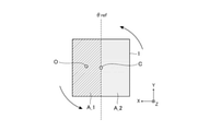
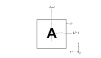
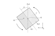
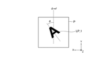
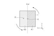
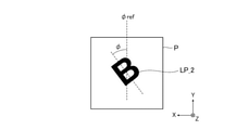
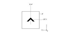
- FIG. It is explanatory drawing which shows the example of the diffraction optical element in the 1st reference state. It is explanatory drawing which shows the example of the projected light pattern in the 1st reference state. It is explanatory drawing which shows the example of the diffraction optical element in the 1st tilt state. It is explanatory drawing which shows the example of the projected light pattern in the 1st inclination state. It is explanatory drawing which shows the example of the diffraction optical element in the 2nd reference state. It is explanatory drawing which shows the example of the projected light pattern in the 2nd reference state.
- FIG. 1 is an explanatory diagram showing a main part of the optical pattern generator according to the first embodiment.
- the optical pattern generator according to the first embodiment will be described with reference to FIG.
- the optical pattern generator 100 includes a diffractive optical element 1, a laser light source 2, and a rotation mechanism 3.
- the diffractive optical element 1 uses one glass substrate or one resin substrate.
- the shape of the diffractive optical element 1 is a single plate.
- the shape of the diffractive optical element 1 is a single rectangular plate.
- the surface portion of the diffractive optical element 1 is arranged to face the laser light source 2.
- the back surface portion of the diffractive optical element 1 is arranged to face the surface (hereinafter referred to as “projected surface”) P on which the optical pattern is projected by the optical pattern generation device 100. That is, the diffractive optical element 1 is arranged between the laser light source 2 and the projected surface P.
- the light pattern to be projected on the projected surface P may be referred to as a "target light pattern”. Further, the intensity distribution corresponding to the target light pattern on the projected surface P may be referred to as “target intensity distribution”. On the other hand, the light pattern projected on the projected surface P or the light pattern projected on the projected surface P may be collectively referred to as a “projected light pattern”.
- the directions along the projected surface P are collectively referred to as "projected surface direction".
- the diffractive optical element 1 is provided parallel to the projected surface P. That is, the diffractive optical element 1 is provided parallel to the XY plane in the drawing, and the projected surface P is provided parallel to the XY plane in the drawing.
- the individual element surface directions are set to be parallel to the corresponding projected surface direction. That is, the individual element plane directions are set to be parallel to the XY plane in the drawing, and the individual projected plane directions are set to be parallel to the XY plane in the drawing.
- the laser light source 2 uses, for example, a semiconductor laser, a fiber laser, or a solid-state laser.
- the laser light source 2 outputs the laser beam L_1.
- the laser light source 2 outputs the laser beam L_1 by CW (Continuous Wave) drive or pulse drive.
- the laser beam L_1 uses, for example, single-wavelength light having a predetermined wavelength ⁇ .
- the laser beam L_1 output by the laser light source 2 irradiates the surface portion of the diffractive optical element 1.
- O_1 shows an example of the optical axis of the laser beam L_1.
- the irradiated laser beam L_1 penetrates into the diffractive optical element 1.
- the invading laser beam L_2 passes through the inside of the diffractive optical element 1.
- O_2 shows an example of the optical axis of the laser beam L_2.
- the passed laser beam L_3 is output to the outside of the diffractive optical element 1 by the back surface portion of the diffractive optical element 1.
- O_3 shows an example of the optical axis of the laser beam L_3.
- the output laser beam L_3 is applied to the projected surface P.
- the irradiated laser beam L_3 is reflected or scattered by the projected surface P.
- an optical pattern corresponding to the intensity distribution of the irradiated laser beam L_3 is realized on the projected surface P.
- the projected surface P is arranged outside the optical pattern generator 100. More specifically, the projected surface P is arranged at a position included in the Fraunhofer region with respect to the diffractive optical element 1. In other words, the projected surface P is arranged at a position included in the Fraunhofer region in the laser beam L_3. That is, the distance D between the diffractive optical element 1 and the projected surface P is set to a value corresponding to such a position.
- the laser beam L passes through the diffractive optical element 1.
- the laser light L when transmitted through the diffractive optical element 1 or the laser light L when transmitted through the diffractive optical element 1 may be collectively referred to as “transmitted light”.
- one of the front surface portion of the diffractive optical element 1 and the back surface portion of the diffractive optical element 1 (hereinafter referred to as “concave surface portion”) is provided with a concavo-convex shape having periodicity. Specifically, for example, a plurality of slit-shaped uneven shapes arranged in a certain direction are provided. By providing such an uneven shape, the transmitted light is diffracted at the uneven surface portion of the diffractive optical element 1.
- the angle of such diffraction is referred to as "diffraction angle”.
- the phase distribution of the laser beam L_1 on the back surface portion of the diffractive optical element 1 changes with respect to the phase distribution of the laser beam L_1 on the front surface portion of the diffractive optical element 1. More specifically, the phase distribution of the laser beam L_3 is such that the Fourier transform image corresponds to the target intensity distribution on the projected surface P. For example, when the target intensity distribution is a sinc function-like distribution, the phase distribution of the laser beam L_3 is a rectangular function-like distribution.
- the phase distribution of the laser beam L_3 on the back surface of the diffractive optical element 1 is a distribution that can realize the target intensity distribution on the projected surface P.
- the target light pattern is realized on the projected surface P. That is, the optical pattern generation device 100 uses the phase type diffractive optical element 1.
- the concave-convex shape on the concave-convex surface portion of the diffractive optical element 1 is designed so that the phase distribution of the laser beam L_3 on the back surface portion of the diffractive optical element 1 corresponds to the target intensity distribution on the projected surface P.
- Various known techniques can be used for designing such an uneven shape. Detailed description of these techniques will be omitted.
- the uneven shape is designed by the iterative Fourier transform method. That is, the uneven shape is designed by the same design method as the design method described in paragraph [0016] of Patent Document 1.
- the rotation mechanism 3 rotates the diffractive optical element 1 in the element surface direction.
- the rotation mechanism 3 uses, for example, a rotary motor.
- the center position C of such rotation is set to a position corresponding to the center of the diffractive optical element 1, for example.
- the rotation mechanism 3 may be one that continuously rotates the diffractive optical element 1, or may be one that intermittently rotates the diffractive optical element 1.
- the tilt angle ⁇ of the diffractive optical element 1 in the element surface direction changes.
- the tilt angle ⁇ of the projected light pattern in the projected plane direction changes.
- each of the reference value ⁇ ref and the reference value ⁇ ref is set to, for example, 0 degrees.
- the main part of the optical pattern generator 100 is configured.
- the diffractive optical element 1 in the optical pattern generator 100 has the following features.
- the concave-convex surface portion of the diffractive optical element 1 includes a plurality of regions (hereinafter referred to as "concave-convex regions") A.
- the concave-convex surface portion of the diffractive optical element 1 includes two concave-convex regions A_1 and A_2 adjacent to each other.
- the two uneven regions A_1 and A_2 are formed by, for example, dividing the concave-convex surface portion of the diffractive optical element 1 in the reference state into left and right.
- the two concavo-convex regions A_1 and A_2 have concavo-convex shapes different from each other.
- the two uneven regions A_1 and A_2 correspond to different optical patterns LP. That is, one concavo-convex region (hereinafter sometimes referred to as "first concavo-convex region”) A_1 corresponds to a predetermined light pattern (hereinafter sometimes referred to as "first optical pattern") LP_1.
- first optical pattern hereinafter sometimes referred to as "first optical pattern”
- the other one uneven region hereinafter, may be referred to as "second uneven region”
- A_2 is another predetermined optical pattern (hereinafter, may be referred to as "second optical pattern”) LP_2. Corresponds to.
- the concavo-convex region A to which the laser beam L_1 of the two concavo-convex regions A_1 and A_1 is irradiated is switched by the rotation of the diffractive optical element 1.
- the light pattern LP projected on the projected surface P of the two light patterns LP_1 and LP_2 is switched. That is, the projected light pattern is switched.
- first reference state when the first uneven region A_1 is irradiated with the laser beam L_1 in the reference state, such a state may be referred to as a “first reference state”.
- second uneven region A_2 when the second uneven region A_2 is irradiated with the laser beam L_1 in the reference state, such a state may be referred to as a “second reference state”.
- first inclined state when the first uneven region A_1 is irradiated with the laser beam L_1 in the inclined state, such a state may be referred to as a “first inclined state”.
- second uneven region A_2 when the second uneven region A_2 is irradiated with the laser beam L_1 in the inclined state, such a state may be referred to as a “second inclined state”.
- the two optical patterns LP_1 and LP_1 have a shape when projected on the projected surface P in the reference state, an inclination when projected on the projected surface P in the reference state, or a reference state. At least one of the positions when projected onto the projected surface P is different from each other. In other words, the two optical patterns LP_1 and LP_2 have at least partially different modes when projected onto the projected surface P in the reference state.
- the shape of the first light pattern LP_1 in the first reference state can be different from the shape of the second light pattern LP_1 in the second reference state.
- the inclination of the first optical pattern LP_1 in the first reference state can be different from the inclination of the second optical pattern LP_1 in the second reference state.
- the position of the first light pattern LP_1 in the first reference state may be different from the position of the second light pattern LP_1 in the second reference state.
- the diffraction angles of the transmitted light are different from each other in the two uneven regions A_1 and A_2. That is, the diffraction angle of the transmitted light in the first concavo-convex region A_1 is different from the diffraction angle of the transmitted light in the second concavo-convex region A_1.
- first specific examples are the two optical patterns LP_1 and LP_2 when they are projected onto the projected surface P in the reference state.
- An example is shown when the shapes are different from each other. That is, the shape of the first optical pattern LP_1 in the first reference state is "A" -shaped (see FIG. 3), whereas the shape of the second optical pattern LP_1 in the second reference state is "B" -shaped. (See FIG. 7).
- the inclination of the first optical pattern LP_1 in the first reference state is the same as the inclination of the second optical pattern LP_1 in the second reference state (see FIG. 7).
- the position of the first optical pattern LP_1 in the first reference state is the same as the position of the second optical pattern LP_1 in the second reference state (see FIG. 7).
- the two optical patterns LP_1 and LP_2 are placed on the projected surface P in the reference state.
- An example is shown in which the positions when projected are different from each other. That is, the position of the first light pattern LP_1 in the first reference state is the central portion of the projected surface P (see FIG. 11), whereas the position of the second light pattern LP_1 in the second reference state is the projected surface. It is the upper end of P (see FIG. 13). This is because the diffraction angle of the transmitted light in the first concavo-convex region A_1 is different from the diffraction angle of the transmitted light in the second concavo-convex region A_1.
- the shape of the first light pattern LP_1 in the first reference state is the same as the shape of the second light pattern LP_1 in the second reference state (see FIG. 13).
- the inclination of the first optical pattern LP_1 in the first reference state is the same as the inclination of the second optical pattern LP_1 in the second reference state (see FIG. 13).
- the diffractive optical element 1 uses one substrate, the concave-convex surface portion thereof includes a plurality of concave-convex regions A.
- Various known techniques can be used for manufacturing the diffractive optical element 1. Detailed description of these techniques will be omitted.
- the diffractive optical element 1 is manufactured by cutting out a single substrate having a plurality of uneven regions A. That is, the diffractive optical element 1 is manufactured by the same manufacturing method as that described in paragraph [0040] of Patent Document 1. As a result, as compared with the case where the diffractive optical element 1 is manufactured using a plurality of substrates corresponding to the plurality of uneven regions A (for example, two substrates corresponding to the two uneven regions A_1 and A_2). The manufacturing cost of the diffractive optical element 1 can be reduced.
- light pattern generation is performed as compared with the case of using a plurality of diffractive optical elements corresponding to a plurality of uneven regions A (for example, two diffractive optical elements corresponding to two uneven regions A_1 and A_2).
- the manufacturing cost of the device 100 can be reduced.
- the rotation mechanism 3 rotates the diffractive optical element 1 in the counterclockwise direction on the paper surface. Further, it is assumed that the XY coordinates of the position corresponding to the optical axis O in the diffractive optical element 1 are constant with respect to such rotation. Further, it is assumed that the XY coordinates of the center position C are also constant with respect to such rotation.
- the left half of the concave-convex surface portion of the diffractive optical element 1 corresponds to the first concave-convex region A_1, and the right half of the concave-convex surface portion of the diffractive optical element 1 corresponds to the first uneven surface region A_1. It corresponds to the second uneven region A_2.
- the right half of the concave-convex surface portion of the diffractive optical element 1 corresponds to the first concave-convex region A_1, and the left half of the concave-convex surface portion of the diffractive optical element 1. The portion corresponds to the second uneven region A_2.
- the first optical pattern LP_1 in the first reference state is a non-inclined “A” -shaped pattern arranged in the center of the projected surface P. That is, the uneven shape in the first uneven region A_1 corresponds to such an "A" -shaped pattern.
- the second optical pattern LP_2 in the second reference state is a non-inclined “B” -shaped pattern arranged at the center of the projected surface P. That is, the uneven shape in the second uneven region A_2 corresponds to such a "B" -shaped pattern.
- the two optical patterns LP_1 and LP_2 have different shapes when projected onto the projected surface P in the reference state (see FIGS. 3 and 7).
- the rotation mechanism 3 rotates the diffractive optical element 1 by ⁇ degrees with respect to the first reference state, so that the first tilted state is realized (see FIGS. 4 and 5).
- the first optical pattern LP_1 is tilted according to the rotation of the diffractive optical element 1.
- the tilt angle ⁇ of the first optical pattern LP_1 becomes a value equivalent to the tilt angle ⁇ of the diffractive optical element 1.
- the second reference state is realized by the rotation mechanism 3 rotating the diffractive optical element 1 by 180 degrees with respect to the first reference state (see FIGS. 6 and 7).
- the rotation mechanism 3 rotates the diffractive optical element 1 by (180- ⁇ ) degrees with respect to the first tilted state, so that the second reference state is realized (see FIGS. 6 and 7).
- the rotation mechanism 3 rotates the diffractive optical element 1 by ⁇ degrees with respect to the second reference state, so that the second tilted state is realized (see FIGS. 8 and 9).
- the second optical pattern LP_2 is tilted according to the rotation of the diffractive optical element 1.
- the tilt angle ⁇ of the second optical pattern LP_2 becomes a value equivalent to the tilt angle ⁇ of the diffractive optical element 1.
- four types of projected light patterns can be realized by using one diffractive optical element 1 (see FIGS. 3, 5, 7, and 9). Further, by making the tilt angles ⁇ in the first tilt state different, it is possible to realize the first optical pattern LP_1 corresponding to the different tilt angles ⁇ . Further, by making the tilt angles ⁇ in the second tilt state different, it is possible to realize the second optical pattern LP_2 corresponding to the different tilt angles ⁇ . This makes it possible to further increase the variation of the projected light pattern.
- the number of uneven regions A in the diffractive optical element 1 can be reduced with respect to the type of projected light pattern realized by the optical pattern generation device 100. This makes it possible to facilitate the design of the diffractive optical element 1. As a result, the manufacturing cost of the optical pattern generator 100 can be further reduced.
- the rotation mechanism 3 rotates the diffractive optical element 1 in the counterclockwise direction on the paper surface. Further, it is assumed that the XY coordinates of the position corresponding to the optical axis O in the diffractive optical element 1 are constant with respect to such rotation. Further, it is assumed that the XY coordinates of the center position C are also constant with respect to such rotation.
- the left half of the concave-convex surface portion of the diffractive optical element 1 corresponds to the first concave-convex region A_1, and the right half of the concave-convex surface portion of the diffractive optical element 1 corresponds to the first concave-convex region A_1. It corresponds to the second uneven region A_2.
- the right half of the concave-convex surface portion of the diffractive optical element 1 corresponds to the first concave-convex region A_1, and the left half of the concave-convex surface portion of the diffractive optical element 1. The portion corresponds to the second uneven region A_2.
- the first optical pattern LP_1 in the first reference state is an upward arrow-shaped pattern arranged at the center of the projected surface P. That is, the uneven shape in the first uneven region A_1 corresponds to the arrow-shaped pattern.
- the second optical pattern LP_2 in the second reference state is an upward arrow-shaped pattern arranged at the upper end of the projected surface P. That is, the uneven shape in the second uneven region A_2 corresponds to the arrow-shaped pattern.
- the two optical patterns LP_1 and LP_2 have different positions when projected onto the projected surface P in the reference state (see FIGS. 11 and 13).
- the second reference state is realized by the rotation mechanism 3 rotating the diffractive optical element 1 by 180 degrees with respect to the first reference state (see FIGS. 12 and 13).
- the rotation mechanism 3 rotates the diffractive optical element 1 by ⁇ degrees with respect to the second reference state, so that the second tilted state is realized (see FIGS. 14 and 15).
- the second optical pattern LP_2 is tilted according to the rotation of the diffractive optical element 1.
- the tilt angle ⁇ of the second optical pattern LP_2 becomes a value equivalent to the tilt angle ⁇ of the diffractive optical element 1.
- three types of projected light patterns can be realized by using one diffractive optical element 1 (see FIGS. 11, 13 and 15).
- four types of projected light patterns can be realized by using the first tilted state (not shown).
- the tilt angles ⁇ in the second tilt state it is possible to realize the second optical pattern LP_2 corresponding to the different tilt angles ⁇ .
- the tilt angles ⁇ in the first tilt state it is possible to realize the first optical pattern LP_1 corresponding to the different tilt angles ⁇ . This makes it possible to further increase the variation of the projected light pattern.
- the number of uneven regions A in the diffractive optical element 1 can be reduced with respect to the type of projected light pattern realized by the optical pattern generation device 100. This makes it possible to facilitate the design of the diffractive optical element 1. As a result, the manufacturing cost of the optical pattern generator 100 can be further reduced.
- an animation in which an arrow moves can be realized by using the above three types of projected light patterns or the above four types of projected light patterns.
- the laser light source 2 outputs the laser beam L_1 by pulse driving. As a result, the laser light source 2 intermittently outputs the laser beam L_1 at a timing corresponding to the pulse timing in the pulse drive.
- the rotation mechanism 3 intermittently rotates the diffractive optical element 1 at a timing corresponding to the pulse timing in the pulse drive. That is, the timing of rotation by the rotation mechanism 3 is synchronized with the pulse timing in pulse drive.
- the rotation amount that is, the change amount ⁇ of the tilt angle ⁇
- the concave-convex shape is provided on the entire concave-convex surface portion of the diffractive optical element 1.
- the concave-convex shape may be provided in a part of the concave-convex surface portion of the diffractive optical element 1. In other words, the concave-convex shape may not be provided on the remaining portion of the concave-convex surface portion of the diffractive optical element 1.
- the concave-convex shape may be provided in a region where the laser beam L can be transmitted in the concave-convex surface portion of the diffractive optical element 1.
- the shape of the diffractive optical element 1 is a single rectangular plate.
- the shape of the diffractive optical element 1 is not limited to such a rectangular plate shape.
- the shape of the diffractive optical element 1 may be any shape as long as the laser beam L can pass through each uneven region A.
- the concave-convex surface portion of the diffractive optical element 1 includes two concave-convex regions A_1 and A_2.
- the number of uneven regions A in the concave-convex surface portion of the diffractive optical element 1 is not limited to two.
- the uneven surface portion of the diffractive optical element 1 may include three or more uneven regions A. That is, the concave-convex surface portion of the diffractive optical element 1 may include a plurality of concave-convex regions A corresponding to different optical patterns LP.
- the following effects can be obtained by using the two uneven regions A_1 and A_2. That is, when the number of uneven regions A is limited to two, the angle range of the inclination related to the projected light pattern is ⁇ 90 ° to + 90 °. This makes it possible to improve the degree of freedom in setting such an inclination.
- the optical pattern generator 100 is used for so-called "road surface lighting".
- the traveling direction of the vehicle can be set on the road surface within the range of ⁇ 90 ° to + 90 °.
- a dynamic obstacle another vehicle, a pedestrian, etc.
- the degree of freedom in setting the inclination is reduced, but the types of projected light patterns can be increased.
- the optical pattern generator 100 it is required to increase the types of projected light patterns. In such a case, it is preferable to increase the number of uneven regions A.
- the concave-convex surface portion of the diffractive optical element 1 in the reference state is divided into two left and right to provide two irregularities. Areas A_1 and A_2 are set.
- the division direction of the uneven surface portion for realizing the plurality of uneven regions A is set to the left-right direction (X-axis direction in the figure) in the reference state.
- the division direction is not limited to the left-right direction (X-axis direction in the figure) in the reference state.
- the division direction may be set in any direction as long as the projection light pattern can be switched by the rotation of the diffractive optical element 1.
- the rotation mechanism 3 rotates the diffractive optical element 1 in the counterclockwise direction on the paper surface. ..
- the rotation direction of the diffractive optical element 1 by the rotation mechanism 3 is not limited to such a direction. That is, the rotation mechanism 3 may replace or in addition to rotating the diffractive optical element 1 in the counterclockwise direction of the paper surface, and may rotate the diffractive optical element 1 in the clockwise direction of the paper surface.
- the position of the diffractive optical element 1 corresponding to the optical axis O is not limited to the examples shown in FIGS. 2 to 15.
- the position corresponding to the optical axis O in the diffractive optical element 1 may be a position included in the corresponding uneven region A among the plurality of uneven regions A at each inclination angle ⁇ .
- the phase type diffractive optical element 1, the laser light source 2 that irradiates the diffractive optical element 1 with the laser beam L, and the diffractive optical element 1 are mounted on the element surface.
- the concavo-convex surface portion of the diffractive optical element 1 includes a revolving mechanism 3 that rotates in a direction, and includes a plurality of concavo-convex regions A corresponding to a plurality of different optical patterns LP, and the diffractive optical element 1 rotates.
- the tilt angle ⁇ of the diffractive optical element 1 in the element surface direction changes.
- the projected light pattern can be switched and the tilt angle ⁇ of the projected light pattern can be changed by using one diffractive optical element 1.
- the plurality of concavo-convex regions A include two concavo-convex regions A_1 and A_2 adjacent to each other, and the diffraction angles of the transmitted light in the two concavo-convex regions A_1 and A_2 are different from each other.
- the diffractive optical element 1 according to the second specific example can be realized.
- the laser light source 2 outputs the laser beam L by pulse drive, and the rotation mechanism 3 rotates the diffractive optical element 1 at a timing corresponding to the pulse timing in the pulse drive. This makes it possible to realize animation with a plurality of types of projected light patterns. Further, it is possible to prevent the optical pattern LP corresponding to the tilt angle ⁇ different from the desired tilt angle ⁇ from being projected on the projected surface P.
- the laser beam L uses a single wavelength light.
- the projected light pattern can be switched by using the single wavelength light, and the inclination angle ⁇ of the projected light pattern can be changed.
- the plurality of concavo-convex regions A include two concavo-convex regions A_1 and A_2 adjacent to each other, and the plurality of optical pattern LPs are two optical patterns LP_1 corresponding to the two concavo-convex regions A_1 and A_1.
- the two optical patterns LP_1 and LP_2, including LP_2, have different shapes when projected onto the projected surface P in the reference state. Due to such a difference in shape, the variation of the projected light pattern can be increased.
- the plurality of concavo-convex regions A include two concavo-convex regions A_1 and A_2 adjacent to each other, and the plurality of optical pattern LPs are two optical patterns LP_1 corresponding to the two concavo-convex regions A_1 and A_1.
- the two optical patterns LP_1 and LP_2, including LP_2, have different inclinations when projected onto the projected surface P in the reference state. Due to this difference in inclination, the variation of the projected light pattern can be increased.
- the plurality of optical patterns LP include two optical patterns LP_1 and LP_2 corresponding to the two uneven regions A_1 and A_2, and the two optical patterns LP_1 and LP_2 are the projected surface P in the reference state. The positions when projected on are different from each other. Due to this difference in position, the variation of the projected light pattern can be increased.
- optical pattern generator according to the present disclosure can be used, for example, for road surface lighting, material processing, printing, optical measurement, or lighting.
- 1 diffractive optical element 2 laser light source, 3 rotation mechanism, 100 optical pattern generator.
Landscapes
- Physics & Mathematics (AREA)
- General Physics & Mathematics (AREA)
- Engineering & Computer Science (AREA)
- Business, Economics & Management (AREA)
- Accounting & Taxation (AREA)
- Marketing (AREA)
- Theoretical Computer Science (AREA)
- Optics & Photonics (AREA)
- Multimedia (AREA)
- Signal Processing (AREA)
- Diffracting Gratings Or Hologram Optical Elements (AREA)
Abstract
光パターン生成装置(100)は、位相型の回折光学素子(1)と、回折光学素子(1)にレーザ光(L)を照射するレーザ光源(2)と、回折光学素子(1)を素子面方向に回動させる回動機構(3)と、を備え、回折光学素子(1)の凹凸面部は、互いに異なる複数個の光パターン(LP)に対応する複数個の凹凸領域(A)を含み、回折光学素子(1)の回動に応じて複数個の凹凸領域(A)のうちのレーザ光(L)が照射される凹凸領域(A)が切り替わることにより、複数個の光パターン(LP)のうちの被投影面(P)における被投影光パターンが切り替わるものであり、回折光学素子(1)の回動に応じて素子面方向における回折光学素子(1)の傾き角度(θ)が変化することにより、被投影面方向における被投影光パターンの傾き角度(φ)が変化するものである。
Description
本開示は、光パターン生成装置に関する。
従来、位相型の回折光学素子を用いた光パターン生成装置が開発されている(例えば、特許文献1参照。)。位相型の回折光学素子を用いることにより、振幅型の回折光学素子を用いる場合に比して、光パターン生成装置におけるエネルギー効率の向上を図ることができる。このため、位相型の回折光学素子を用いるのが好適である。
特許文献1記載の光パターン生成装置は、以下のように構成されている。すなわち、1枚の円板状の回折光学素子の片面部が円周方向にn分割されている。これにより、n個の領域が設定されている(例えば、特許文献1の図2参照。)。n個の領域は、互いに異なる凹凸形状を有するものである。これにより、n個の領域は、互いに異なる光パターンに対応するものである。換言すれば、n個の領域は、n個の光パターンにそれぞれ対応するものである。
以下、板状の回折光学素子における板面に沿う方向を総称して「素子面方向」という。特許文献1記載の光パターン生成装置において、回折光学素子は、素子面方向に対して回動自在に設けられている。回折光学素子が回動することにより、n個の領域のうちのレーザ光が照射される領域が切り替わる。これにより、1枚の回折光学素子を用いて、n個の光パターンのうちの投影される光パターンを切り替えることができる。
ここで、特許文献1記載の光パターン生成装置に対する従来の光パターン生成装置は、投影される光パターンの切替えに液晶素子を用いるものであった。このため、従来の光パターン生成装置においては、液晶素子を設けることが要求されるとともに、液晶素子用の電圧源を設けることが要求される。これにより、光パターン生成装置が大型になる問題があった。また、光パターン生成装置が高価になる問題があった。
これに対して、特許文献1記載の光パターン生成装置においては、液晶素子を設けることが不要である。また、液晶素子用の電圧源を設けることも不要である。このため、特許文献1記載の光パターン生成装置を用いることにより、従来の光パターン生成装置を用いる場合に比して、光パターン生成装置を小型にすることができる。また、光パターン生成装置を安価にすることができる。
しかしながら、特許文献1記載の光パターン生成装置においては、以下のような問題があった。すなわち、特許文献1記載の光パターン生成装置においては、個々の光パターンが投影されるとき、投影された光パターンの傾き角度が互いに同一の傾きに対応するものとなるように設計されている(例えば、特許文献1の段落[0031]参照。)。これにより、投影される光パターンの切替えに対応しているものの、そのバリエーションが少ないという問題があった。より具体的には、その傾きのバリエーションが少ないという問題があった。
本開示は、上記のような課題を解決するためになされたものであり、1枚の回折光学素子を用いて、投影される光パターンを切り替えることができ、かつ、投影された光パターンの傾き角度を変化させることができる光パターン生成装置を提供することを目的とする。
本開示に係る光パターン生成装置は、位相型の回折光学素子と、回折光学素子にレーザ光を照射するレーザ光源と、回折光学素子を素子面方向に回動させる回動機構と、を備え、回折光学素子の凹凸面部は、互いに異なる複数個の光パターンに対応する複数個の凹凸領域を含み、回折光学素子の回動に応じて複数個の凹凸領域のうちのレーザ光が照射される凹凸領域が切り替わることにより、複数個の光パターンのうちの被投影面における被投影光パターンが切り替わるものであり、回折光学素子の回動に応じて素子面方向における回折光学素子の傾き角度が変化することにより、被投影面方向における被投影光パターンの傾き角度が変化するものである。
本開示によれば、上記のように構成したので、1枚の回折光学素子を用いて、投影される光パターンを切り替えることができるとともに、投影された光パターンの傾き角度を変化させることができる。
以下、この開示をより詳細に説明するために、この開示を実施するための形態について、添付の図面に従って説明する。
実施の形態1.
図1は、実施の形態1に係る光パターン生成装置の要部を示す説明図である。図1を参照して、実施の形態1に係る光パターン生成装置について説明する。
図1は、実施の形態1に係る光パターン生成装置の要部を示す説明図である。図1を参照して、実施の形態1に係る光パターン生成装置について説明する。
図1に示す如く、光パターン生成装置100は、回折光学素子1、レーザ光源2及び回動機構3を含むものである。
回折光学素子1は、ガラス製の1枚の基板又は樹脂製の1枚の基板を用いたものである。これにより、回折光学素子1の形状は、1枚の板状である。具体的には、例えば、回折光学素子1の形状は、1枚の矩形板状である。回折光学素子1の表面部は、レーザ光源2と対向配置されている。他方、回折光学素子1の裏面部は、光パターン生成装置100により光パターンが投影される面(以下「被投影面」という。)Pと対向配置されている。すなわち、回折光学素子1は、レーザ光源2と被投影面P間に配置されている。
以下、被投影面Pに投影されるべき光パターンを「目標光パターン」ということがある。また、被投影面Pにおける目標光パターンに対応する強度分布を「目標強度分布」ということがある。これに対して、被投影面Pに投影される光パターン又は被投影面Pに投影された光パターンを総称して「被投影光パターン」ということがある。
以下、被投影面Pに沿う方向を総称して「被投影面方向」という。図1に示す例においては、回折光学素子1が被投影面Pに対して平行に設けられている。すなわち、回折光学素子1が図中XY平面に対して平行に設けられており、かつ、被投影面Pが図中XY平面に対して平行に設けられている。これにより、図1に示す例においては、個々の素子面方向が対応する被投影面方向に対して平行な方向に設定されている。すなわち、個々の素子面方向が図中XY平面に対して平行な方向に設定されており、かつ、個々の被投影面方向が図中XY平面に対して平行な方向に設定されている。
レーザ光源2は、例えば、半導体レーザ、ファイバレーザ又は固体レーザを用いたものである。レーザ光源2は、レーザ光L_1を出力するものである。具体的には、例えば、レーザ光源2は、CW(Continuous Wave)駆動又はパルス駆動によりレーザ光L_1を出力するのである。レーザ光L_1は、例えば、所定の波長λを有する単一波長光を用いたものである。
レーザ光源2により出力されたレーザ光L_1は、回折光学素子1の表面部に照射される。図中、O_1は、レーザ光L_1の光軸の例を示している。当該照射されたレーザ光L_1は、回折光学素子1の内部に侵入する。当該侵入したレーザ光L_2は、回折光学素子1の内部を通過する。図中、O_2は、レーザ光L_2の光軸の例を示している。当該通過したレーザ光L_3は、回折光学素子1の裏面部により回折光学素子1の外部に出力される。図中、O_3は、レーザ光L_3の光軸の例を示している。当該出力されたレーザ光L_3は、被投影面Pに照射される。当該照射されたレーザ光L_3は、被投影面Pにより反射又は散乱される。これにより、被投影面Pにて、当該照射されたレーザ光L_3の強度分布に対応する光パターンが実現される。
被投影面Pは、光パターン生成装置100の外部に配置されている。より具体的には、被投影面Pは、回折光学素子1に対するフラウンホーファ領域に含まれる位置に配置されている。換言すれば、被投影面Pは、レーザ光L_3におけるフラウンホーファ領域に含まれる位置に配置されている。すなわち、回折光学素子1と被投影面P間の距離Dは、かかる位置に対応する値に設定されている。
このように、光パターン生成装置100においては、レーザ光Lが回折光学素子1を透過するものである。以下、回折光学素子1を透過するときのレーザ光L又は回折光学素子1を透過したときのレーザ光Lを総称して「透過光」ということがある。
ここで、回折光学素子1の表面部及び回折光学素子1の裏面部のうちのいずれか一方(以下「凹凸面部」という。)には、周期性を有する凹凸形状が設けられている。具体的には、例えば、一定方向に配列された複数本のスリット状の凹凸形状が設けられている。かかる凹凸形状が設けられていることにより、回折光学素子1の凹凸面部にて透過光が回折する。以下、かかる回折の角度を「回折角度」という。
また、かかる凹凸形状が設けられていることにより、回折光学素子1の表面部におけるレーザ光L_1の位相分布に対して、回折光学素子1の裏面部におけるレーザ光L_3の位相分布が変化する。より具体的には、レーザ光L_3の位相分布は、そのフーリエ変換像が被投影面Pにおける目標強度分布に対応した分布となる。例えば、目標強度分布がsinc関数状の分布であるとき、レーザ光L_3の位相分布が矩形関数状の分布となる。
換言すれば、回折光学素子1の裏面部におけるレーザ光L_3の位相分布は、被投影面Pにおける目標強度分布を実現可能な分布となる。これにより、被投影面Pにて目標光パターンが実現される。すなわち、光パターン生成装置100は、位相型の回折光学素子1を用いたものである。
したがって、回折光学素子1の凹凸面部における凹凸形状は、回折光学素子1の裏面部におけるレーザ光L_3の位相分布が被投影面Pにおける目標強度分布に対応する分布となるように設計されたものである。かかる凹凸形状の設計には、公知の種々の技術を用いることができる。これらの技術についての詳細な説明は省略する。
具体的には、例えば、かかる凹凸形状は、反復フーリエ変換法により設計されたものである。すなわち、かかる凹凸形状は、特許文献1の段落[0016]に記載された設計方法と同様の設計方法により設計されたものである。
回動機構3は、回折光学素子1を素子面方向に回動させるものである。回動機構3は、例えば、回転式のモータを用いたものである。かかる回動の中心位置Cは、例えば、回折光学素子1の中心部に対応する位置に設定されている。なお、回動機構3は、回折光学素子1を連続的に回動させるものであっても良く、又は回折光学素子1を断続的に回動させるものであっても良い。
ここで、回折光学素子1が回動することにより、素子面方向における回折光学素子1の傾き角度θが変化するようになっている。傾き角度θが変化することより、被投影面方向における被投影光パターンの傾き角度φが変化するようになっている。
以下、傾き角度θが所定の基準値θrefと同等の値であるとき(すなわち傾き角度φが所定の基準値φrefと同等の値であるとき)、かかる状態を「基準状態」という。他方、傾き角度θが基準値θrefと異なる値であるとき(すなわち傾き角度φが基準値φrefと異なる値であるとき)、かかる状態を「傾斜状態」という。すなわち、基準値θref及び基準値φrefの各々は、例えば、0度に設定されている。
このようにして、光パターン生成装置100の要部が構成されている。
ここで、光パターン生成装置100における回折光学素子1は、以下のような特徴を有するものである。
すなわち、回折光学素子1の凹凸面部は、複数個の領域(以下「凹凸領域」という。)Aを含むものである。具体的には、例えば、回折光学素子1の凹凸面部は、互いに隣接する2個の凹凸領域A_1,A_2を含むものである。2個の凹凸領域A_1,A_2は、例えば、基準状態における回折光学素子1の凹凸面部を左右に二分割してなるものである。
2個の凹凸領域A_1,A_2は、互いに異なる凹凸形状を有するものである。これにより、2個の凹凸領域A_1,A_2は、互いに異なる光パターンLPに対応するものである。すなわち、1個の凹凸領域(以下「第1凹凸領域」ということがある。)A_1は、所定の光パターン(以下「第1光パターン」ということがある。)LP_1に対応するものである。これに対して、他の1個の凹凸領域(以下「第2凹凸領域」ということがある。)A_2は、他の所定の光パターン(以下「第2光パターン」ということがある。)LP_2に対応するものである。
光パターン生成装置100においては、回折光学素子1が回動することにより、2個の凹凸領域A_1,A_2のうちのレーザ光L_1が照射される凹凸領域Aが切り替わるようになっている。これにより、2個の光パターンLP_1,LP_2のうちの被投影面Pに投影される光パターンLPが切り替わるようになっている。すなわち、被投影光パターンが切り替わるようになっている。
以下、基準状態にて第1凹凸領域A_1にレーザ光L_1が照射される状態であるとき、かかる状態を「第1基準状態」ということがある。また、基準状態にて第2凹凸領域A_2にレーザ光L_1が照射される状態であるとき、かかる状態を「第2基準状態」ということがある。また、傾斜状態にて第1凹凸領域A_1にレーザ光L_1が照射される状態であるとき、かかる状態を「第1傾斜状態」ということがある。また、傾斜状態にて第2凹凸領域A_2にレーザ光L_1が照射される状態であるとき、かかる状態を「第2傾斜状態」ということがある。
ここで、2個の光パターンLP_1,LP_2は、基準状態にて被投影面Pに投影されたときの形状、基準状態にて被投影面Pに投影されたときの傾き、又は基準状態にて被投影面Pに投影されたときの位置のうちの少なくとも一つが互いに異なるものである。換言すれば、2個の光パターンLP_1,LP_2は、基準状態にて被投影面Pに投影されたときの態様が少なくとも部分的に異なるものである。
すなわち、第1基準状態における第1光パターンLP_1の形状は、第2基準状態における第2光パターンLP_2の形状と異なり得るものである。また、第1基準状態における第1光パターンLP_1の傾きは、第2基準状態における第2光パターンLP_2の傾きと異なり得るものである。また、第1基準状態における第1光パターンLP_1の位置は、第2基準状態における第2光パターンLP_2の位置と異なり得るものである。
なお、かかる位置が互いに異なるものであるとき、2個の凹凸領域A_1,A_2においては、透過光の回折角度が互いに異なるものである。すなわち、第1凹凸領域A_1における透過光の回折角度が第2凹凸領域A_2における透過光の回折角度と異なるものである。
図2~図9を参照して後述する具体例(以下「第1具体例」という。)は、2個の光パターンLP_1,LP_2について、基準状態にて被投影面Pに投影されたときの形状が互いに異なる場合の例を示している。すなわち、第1基準状態における第1光パターンLP_1の形状が「A」字状であるのに対して(図3参照)、第2基準状態における第2光パターンLP_2の形状が「B」字状である(図7参照)。
なお、第1具体例において、第1基準状態における第1光パターンLP_1の傾き(図3参照)は、第2基準状態における第2光パターンLP_2の傾き(図7参照)と同一である。また、第1具体例において、第1基準状態における第1光パターンLP_1の位置(図3参照)は、第2基準状態における第2光パターンLP_2の位置(図7参照)と同一である。
これに対して、図10~図15を参照して後述する具体例(以下「第2具体例」という。)は、2個の光パターンLP_1,LP_2について、基準状態にて被投影面Pに投影されたときの位置が互いに異なる場合の例を示している。すなわち、第1基準状態における第1光パターンLP_1の位置が被投影面Pの中心部であるのに対して(図11参照)、第2基準状態における第2光パターンLP_2の位置が被投影面Pの上端部である(図13参照)。これは、第1凹凸領域A_1における透過光の回折角度が第2凹凸領域A_2における透過光の回折角度と異なることによるものである。
なお、第2具体例において、第1基準状態における第1光パターンLP_1の形状(図11参照)は、第2基準状態における第2光パターンLP_2の形状(図13参照)と同一である。また、第2具体例において、第1基準状態における第1光パターンLP_1の傾き(図11参照)は、第2基準状態における第2光パターンLP_2の傾き(図13参照)と同一である。
このように、回折光学素子1は、1枚の基板を用いたものでありながら、その凹凸面部に複数個の凹凸領域Aを含むものである。かかる回折光学素子1の製造には、公知の種々の技術を用いることができる。これらの技術についての詳細な説明は省略する。
具体的には、例えば、回折光学素子1は、複数個の凹凸領域Aを有する1枚の基板に対する切り出しにより製造されたものである。すなわち、回折光学素子1は、特許文献1の段落[0040]に記載された製造方法と同様の製造方法により製造されたものである。これにより、複数個の凹凸領域Aに対応する複数枚の基板(例えば2個の凹凸領域A_1,A_2に対応する2枚の基板)を用いて回折光学素子1を製造する場合に比して、回折光学素子1の製造コストを低減することができる。換言すれば、複数個の凹凸領域Aに対応する複数枚の回折光学素子(例えば2個の凹凸領域A_1,A_2に対応する2枚の回折光学素子)を用いる場合に比して、光パターン生成装置100の製造コストを低減することができる。
次に、図2~図9を参照して、回折光学素子1及び被投影光パターンに係る第1具体例について説明する。
なお、第1具体例において、回動機構3は、回折光学素子1を紙面反時計回り方向に回動させるものとする。また、回折光学素子1における光軸Oに対応する位置のXY座標は、かかる回動に対して一定であるものとする。また、中心位置CのXY座標も、かかる回動に対して一定であるものとする。
図2に示す如く、第1基準状態においては、回折光学素子1の凹凸面部の左半部が第1凹凸領域A_1に対応するものとなり、かつ、回折光学素子1の凹凸面部の右半部が第2凹凸領域A_2に対応するものとなる。他方、図6に示す如く、第2基準状態においては、回折光学素子1の凹凸面部の右半部が第1凹凸領域A_1に対応するものとなり、かつ、回折光学素子1の凹凸面部の左半部が第2凹凸領域A_2に対応するものとなる。
図3に示す如く、第1基準状態における第1光パターンLP_1は、被投影面Pの中心部に配置された非傾斜の「A」字状のパターンとなる。すなわち、第1凹凸領域A_1における凹凸形状は、かかる「A」字状のパターンに対応するものである。他方、図7に示す如く、第2基準状態における第2光パターンLP_2は、被投影面Pの中心部に配置された非傾斜の「B」字状のパターンとなる。すなわち、第2凹凸領域A_2における凹凸形状は、かかる「B」字状のパターンに対応するものである。
このように、2個の光パターンLP_1,LP_2は、基準状態にて被投影面Pに投影されたときの形状が互いに異なるものである(図3及び図7参照)。
第1基準状態に対して、回動機構3が回折光学素子1をθ度回動させることにより、第1傾斜状態が実現される(図4及び図5参照)。このとき、回折光学素子1の回動に応じて第1光パターンLP_1が傾く。この結果、第1光パターンLP_1の傾き角度φは、回折光学素子1の傾き角度θと同等の値となる。
第1基準状態に対して、回動機構3が回折光学素子1を180度回動させることにより、第2基準状態が実現される(図6及び図7参照)。または、第1傾斜状態に対して、回動機構3が回折光学素子1を(180-θ)度回動させることにより、第2基準状態が実現される(図6及び図7参照)。
第2基準状態に対して、回動機構3が回折光学素子1をθ度回動させることにより、第2傾斜状態が実現される(図8及び図9参照)。このとき、回折光学素子1の回動に応じて第2光パターンLP_2が傾く。この結果、第2光パターンLP_2の傾き角度φは、回折光学素子1の傾き角度θと同等の値となる。
このように、第1具体例においては、1枚の回折光学素子1を用いて4種類の被投影光パターンを実現することができる(図3、図5、図7及び図9参照)。また、第1傾斜状態における傾き角度θを異ならしめることにより、異なる傾き角度φに対応する第1光パターンLP_1を実現することができる。また、第2傾斜状態における傾き角度θを異ならしめることにより、異なる傾き角度φに対応する第2光パターンLP_2を実現することができる。これにより、被投影光パターンのバリエーションを更に増やすことができる。
換言すれば、光パターン生成装置100により実現される被投影光パターンの種類に対して、回折光学素子1における凹凸領域Aの個数を低減することができる。これにより、回折光学素子1の設計を容易にすることができる。この結果、光パターン生成装置100の製造コストを更に低減することができる。
次に、図10~図15を参照して、回折光学素子1及び被投影光パターンに係る第2具体例について説明する。
なお、第2具体例において、回動機構3は、回折光学素子1を紙面反時計回り方向に回動させるものとする。また、回折光学素子1における光軸Oに対応する位置のXY座標は、かかる回動に対して一定であるものとする。また、中心位置CのXY座標も、かかる回動に対して一定であるものとする。
図10に示す如く、第1基準状態においては、回折光学素子1の凹凸面部の左半部が第1凹凸領域A_1に対応するものとなり、かつ、回折光学素子1の凹凸面部の右半部が第2凹凸領域A_2に対応するものとなる。他方、図12に示す如く、第2基準状態においては、回折光学素子1の凹凸面部の右半部が第1凹凸領域A_1に対応するものとなり、かつ、回折光学素子1の凹凸面部の左半部が第2凹凸領域A_2に対応するものとなる。
図11に示す如く、第1基準状態における第1光パターンLP_1は、被投影面Pの中心部に配置された上方矢印状のパターンとなる。すなわち、第1凹凸領域A_1における凹凸形状は、かかる矢印状のパターンに対応するものである。他方、図13に示す如く、第2基準状態における第2光パターンLP_2は、被投影面Pの上端部に配置された上方矢印状のパターンとなる。すなわち、第2凹凸領域A_2における凹凸形状は、かかる矢印状のパターンに対応するものである。
このように、2個の光パターンLP_1,LP_2は、基準状態にて被投影面Pに投影されたときの位置が互いに異なるものである(図11及び図13参照)。
第1基準状態に対して、回動機構3が回折光学素子1を180度回動させることにより、第2基準状態が実現される(図12及び図13参照)。
第2基準状態に対して、回動機構3が回折光学素子1をθ度回動させることにより、第2傾斜状態が実現される(図14及び図15参照)。このとき、回折光学素子1の回動に応じて第2光パターンLP_2が傾く。この結果、第2光パターンLP_2の傾き角度φは、回折光学素子1の傾き角度θと同等の値となる。
このように、第2具体例においては、1枚の回折光学素子1を用いて3種類の被投影光パターンを実現することができる(図11、図13及び図15参照)。これに加えて、第1傾斜状態(不図示)を用いることにより、4種類の被投影光パターンを実現することもできる。また、第2傾斜状態における傾き角度θを異ならしめることにより、異なる傾き角度φに対応する第2光パターンLP_2を実現することができる。さらに、第1傾斜状態(不図示)における傾き角度θを異ならしめることにより、異なる傾き角度φに対応する第1光パターンLP_1を実現することもできる。これにより、被投影光パターンのバリエーションを更に増やすことができる。
換言すれば、光パターン生成装置100により実現される被投影光パターンの種類に対して、回折光学素子1における凹凸領域Aの個数を低減することができる。これにより、回折光学素子1の設計を容易にすることができる。この結果、光パターン生成装置100の製造コストを更に低減することができる。
ここで、以下のような構成を採用することにより、複数種類の被投影光パターンによるアニメーションを実現することができる。具体的には、例えば、上記3種類の被投影光パターン又は上記4種類の被投影光パターンを用いて、矢印が動くアニメーションを実現することができる。
すなわち、レーザ光源2は、パルス駆動によりレーザ光L_1を出力する。これにより、レーザ光源2は、パルス駆動におけるパルスタイミングに応じたタイミングにて断続的にレーザ光L_1を出力する。
このとき、回動機構3は、パルス駆動におけるパルスタイミングに応じたタイミングにて断続的に回折光学素子1を回動させる。すなわち、パルス駆動におけるパルスタイミングに対して、回動機構3による回動のタイミングを同期させる。各回の回動における回動量(すなわち傾き角度θの変化量Δθ)を設定することにより、各回のレーザ光L_1の出力時における被投影光パターンの傾き角度φを制御することができるとともに、被投影光パターンが切り替わるタイミングを制御することができる。
これにより、複数種類の被投影光パターンによるアニメーションを実現することができる。また、所望の傾き角度φと異なる傾き角度φに対応する光パターンLPが被投影面Pに投影されるのを回避することができる。
次に、光パターン生成装置100の変形例について説明する。
第1具体例(図2~図9参照)及び第2具体例(図10~図15参照)においては、回折光学素子1の凹凸面部の全体に凹凸形状が設けられている。これに対して、回折光学素子1の凹凸面部における一部の部位に凹凸形状が設けられているものであっても良い。換言すれば、回折光学素子1の凹凸面部における残余の部位に凹凸形状が設けられていないものであっても良い。かかる凹凸形状は、回折光学素子1の凹凸面部におけるレーザ光Lが透過し得る領域に設けられているものであれば良い。
第1具体例(図2~図9参照)及び第2具体例(図10~図15参照)においては、回折光学素子1の形状が1枚の矩形板状である。しかしながら、回折光学素子1の形状は、かかる矩形板状に限定されるものではない。回折光学素子1の形状は、レーザ光Lが個々の凹凸領域Aを透過可能な形状であれば良い。
第1具体例(図2~図9参照)及び第2具体例(図10~図15参照)においては、回折光学素子1の凹凸面部が2個の凹凸領域A_1,A_2を含むものである。しかしながら、回折光学素子1の凹凸面部における凹凸領域Aの個数は、2個に限定されるものではない。回折光学素子1の凹凸面部は、3個以上の凹凸領域Aを含むものであっても良い。すなわち、回折光学素子1の凹凸面部は、互いに異なる光パターンLPに対応する複数個の凹凸領域Aを含むものであれば良い。
ただし、2個の凹凸領域A_1,A_2を用いることにより、以下のような効果が得られる。すなわち、凹凸領域Aの個数が2個に限定されている場合、被投影光パターンに係る傾きの角度範囲が-90°~+90°になる。これにより、かかる傾きの設定の自由度を向上することができる。
例えば、いわゆる「路面ライティング」に光パターン生成装置100が用いられるものであるとする。この場合において、第2具体例に係る矢印状のパターンを用いることにより、車両(乗用車、特殊車両、工場における自走ロボット等)の進行方向を-90°~+90°の範囲内にて路面に表示することができる。これにより、動的障害物(他車両、歩行者等)が当該車両に衝突するのを回避することができる。当該車両によるバック走行を考慮しない場合、かかる範囲内にて矢印状のパターンを回転させることにより、当該車両による全ての進行方向に対応することができる。これは、凹凸領域Aの個数が2個に限定されていることによる有利な効果である。
なお、凹凸領域Aの個数が増加することにより、かかる傾きの設定の自由度が低下するものの、被投影光パターンの種類を増やすことができる。光パターン生成装置100の用途によっては、被投影光パターンの種類を増やすことが要求される。このような場合、凹凸領域Aの個数を増やすのが好適である。
第1具体例(図2~図9参照)及び第2具体例(図10~図15参照)においては、基準状態における回折光学素子1の凹凸面部を左右に二分割することにより2個の凹凸領域A_1,A_2が設定されている。換言すれば、複数個の凹凸領域Aを実現するための凹凸面部の分割方向が基準状態における左右方向(図中X軸方向)に設定されている。しかしながら、かかる分割方向は、基準状態における左右方向(図中X軸方向)に限定されるものではない。かかる分割方向は、回折光学素子1の回動による被投影光パターンの切替えが実現される方向であれば、如何なる方向に設定されたものであっても良い。
第1具体例(図2~図9参照)及び第2具体例(図10~図15参照)においては、回動機構3が回折光学素子1を紙面反時計回り方向に回動させるものである。しかしながら、回動機構3による回折光学素子1の回動方向は、かかる方向に限定されるものではない。すなわち、回動機構3は、回折光学素子1を紙面反時計回り方向に回動させるのに代えて又は加えて、回折光学素子1を紙面時計回り方向に回動させるものであっても良い。
回折光学素子1における光軸Oに対応する位置は、図2~図15に示す例に限定されるものではない。回折光学素子1における光軸Oに対応する位置は、個々の傾き角度θにおいて、複数個の凹凸領域Aのうちの対応する凹凸領域Aに含まれる位置であれば良い。
以上のように、実施の形態1に係る光パターン生成装置100は、位相型の回折光学素子1と、回折光学素子1にレーザ光Lを照射するレーザ光源2と、回折光学素子1を素子面方向に回動させる回動機構3と、を備え、回折光学素子1の凹凸面部は、互いに異なる複数個の光パターンLPに対応する複数個の凹凸領域Aを含み、回折光学素子1の回動に応じて複数個の凹凸領域Aのうちのレーザ光Lが照射される凹凸領域Aが切り替わることにより、複数個の光パターンLPのうちの被投影面Pにおける被投影光パターンが切り替わるものであり、回折光学素子1の回動に応じて素子面方向における回折光学素子1の傾き角度θが変化することにより、被投影面方向における被投影光パターンの傾き角度φが変化するものである。これにより、1枚の回折光学素子1を用いて、被投影光パターンを切り替えることができるとともに、被投影光パターンの傾き角度φを変化させることができる。
また、複数個の凹凸領域Aは、互いに隣接する2個の凹凸領域A_1,A_2を含み、2個の凹凸領域A_1,A_2における透過光の回折角度が互いに異なるものである。これにより、例えば、第2具体例に係る回折光学素子1を実現することができる。
また、レーザ光源2は、パルス駆動によりレーザ光Lを出力するものであり、回動機構3は、パルス駆動におけるパルスタイミングに応じたタイミングにて回折光学素子1を回動させるものである。これにより、複数種類の被投影光パターンによるアニメーションを実現することができる。また、所望の傾き角度φと異なる傾き角度φに対応する光パターンLPが被投影面Pに投影されるのを回避することができる。
また、レーザ光Lは、単一波長光を用いたものである。これにより、単一波長光を用いて、被投影光パターンを切り替えることができるとともに、被投影光パターンの傾き角度φを変化させることができる。
また、複数個の凹凸領域Aは、互いに隣接する2個の凹凸領域A_1,A_2を含み、複数個の光パターンLPは、2個の凹凸領域A_1,A_2に対応する2個の光パターンLP_1,LP_2を含み、2個の光パターンLP_1,LP_2は、基準状態にて被投影面Pに投影されたときの形状が互いに異なるものである。かかる形状の相違により、被投影光パターンのバリエーションを増やすことができる。
また、複数個の凹凸領域Aは、互いに隣接する2個の凹凸領域A_1,A_2を含み、複数個の光パターンLPは、2個の凹凸領域A_1,A_2に対応する2個の光パターンLP_1,LP_2を含み、2個の光パターンLP_1,LP_2は、基準状態にて被投影面Pに投影されたときの傾きが互いに異なるものである。かかる傾きの相違により、被投影光パターンのバリエーションを増やすことができる。
また、複数個の光パターンLPは、2個の凹凸領域A_1,A_2に対応する2個の光パターンLP_1,LP_2を含み、2個の光パターンLP_1,LP_2は、基準状態にて被投影面Pに投影されたときの位置が互いに異なるものである。かかる位置の相違により、被投影光パターンのバリエーションを増やすことができる。
なお、本願開示はその開示の範囲内において、実施の形態の任意の構成要素の変形、もしくは実施の形態の任意の構成要素の省略が可能である。
本開示に係る光パターン生成装置は、例えば、路面ライティング、材料加工、印刷、光学計測又は照明に用いることができる。
1 回折光学素子、2 レーザ光源、3 回動機構、100 光パターン生成装置。
Claims (7)
- 位相型の回折光学素子と、前記回折光学素子にレーザ光を照射するレーザ光源と、前記回折光学素子を素子面方向に回動させる回動機構と、を備え、
前記回折光学素子の凹凸面部は、互いに異なる複数個の光パターンに対応する複数個の凹凸領域を含み、
前記回折光学素子の回動に応じて前記複数個の凹凸領域のうちの前記レーザ光が照射される凹凸領域が切り替わることにより、前記複数個の光パターンのうちの被投影面における被投影光パターンが切り替わるものであり、
前記回折光学素子の回動に応じて前記素子面方向における前記回折光学素子の傾き角度が変化することにより、被投影面方向における前記被投影光パターンの傾き角度が変化するものである
ことを特徴とする光パターン生成装置。 - 前記複数個の凹凸領域は、互いに隣接する2個の凹凸領域を含み、
前記2個の凹凸領域における透過光の回折角度が互いに異なるものである
ことを特徴とする請求項1記載の光パターン生成装置。 - 前記レーザ光源は、パルス駆動により前記レーザ光を出力するものであり、
前記回動機構は、前記パルス駆動におけるパルスタイミングに応じたタイミングにて前記回折光学素子を回動させるものである
ことを特徴とする請求項1記載の光パターン生成装置。 - 前記レーザ光は、単一波長光を用いたものであることを特徴とする請求項1記載の光パターン生成装置。
- 前記複数個の凹凸領域は、互いに隣接する2個の凹凸領域を含み、
前記複数個の光パターンは、前記2個の凹凸領域に対応する2個の光パターンを含み、
前記2個の光パターンは、基準状態にて前記被投影面に投影されたときの形状が互いに異なるものである
ことを特徴とする請求項1記載の光パターン生成装置。 - 前記複数個の凹凸領域は、互いに隣接する2個の凹凸領域を含み、
前記複数個の光パターンは、前記2個の凹凸領域に対応する2個の光パターンを含み、
前記2個の光パターンは、基準状態にて前記被投影面に投影されたときの傾きが互いに異なるものである
ことを特徴とする請求項1記載の光パターン生成装置。 - 前記複数個の光パターンは、前記2個の凹凸領域に対応する2個の光パターンを含み、
前記2個の光パターンは、基準状態にて前記被投影面に投影されたときの位置が互いに異なるものである
ことを特徴とする請求項2記載の光パターン生成装置。
Priority Applications (2)
| Application Number | Priority Date | Filing Date | Title |
|---|---|---|---|
| JP2022536056A JP7205001B2 (ja) | 2020-07-16 | 2020-07-16 | 光パターン生成装置 |
| PCT/JP2020/027595 WO2022013992A1 (ja) | 2020-07-16 | 2020-07-16 | 光パターン生成装置 |
Applications Claiming Priority (1)
| Application Number | Priority Date | Filing Date | Title |
|---|---|---|---|
| PCT/JP2020/027595 WO2022013992A1 (ja) | 2020-07-16 | 2020-07-16 | 光パターン生成装置 |
Publications (1)
| Publication Number | Publication Date |
|---|---|
| WO2022013992A1 true WO2022013992A1 (ja) | 2022-01-20 |
Family
ID=79554525
Family Applications (1)
| Application Number | Title | Priority Date | Filing Date |
|---|---|---|---|
| PCT/JP2020/027595 Ceased WO2022013992A1 (ja) | 2020-07-16 | 2020-07-16 | 光パターン生成装置 |
Country Status (2)
| Country | Link |
|---|---|
| JP (1) | JP7205001B2 (ja) |
| WO (1) | WO2022013992A1 (ja) |
Cited By (1)
| Publication number | Priority date | Publication date | Assignee | Title |
|---|---|---|---|---|
| CN116222432A (zh) * | 2022-12-08 | 2023-06-06 | 中国科学院半导体研究所 | 结构光投影装置 |
Citations (4)
| Publication number | Priority date | Publication date | Assignee | Title |
|---|---|---|---|---|
| JP2000280085A (ja) * | 1999-03-30 | 2000-10-10 | Seiko Epson Corp | レーザ加工装置及びその加工方法 |
| US20080273176A1 (en) * | 2007-05-04 | 2008-11-06 | Beverly Lloyd | Display device and method |
| JP6508425B1 (ja) * | 2018-01-11 | 2019-05-08 | 三菱電機株式会社 | 光パターン生成装置 |
| WO2019117042A1 (ja) * | 2017-12-13 | 2019-06-20 | 株式会社小糸製作所 | 車両用灯具 |
-
2020
- 2020-07-16 JP JP2022536056A patent/JP7205001B2/ja active Active
- 2020-07-16 WO PCT/JP2020/027595 patent/WO2022013992A1/ja not_active Ceased
Patent Citations (4)
| Publication number | Priority date | Publication date | Assignee | Title |
|---|---|---|---|---|
| JP2000280085A (ja) * | 1999-03-30 | 2000-10-10 | Seiko Epson Corp | レーザ加工装置及びその加工方法 |
| US20080273176A1 (en) * | 2007-05-04 | 2008-11-06 | Beverly Lloyd | Display device and method |
| WO2019117042A1 (ja) * | 2017-12-13 | 2019-06-20 | 株式会社小糸製作所 | 車両用灯具 |
| JP6508425B1 (ja) * | 2018-01-11 | 2019-05-08 | 三菱電機株式会社 | 光パターン生成装置 |
Cited By (1)
| Publication number | Priority date | Publication date | Assignee | Title |
|---|---|---|---|---|
| CN116222432A (zh) * | 2022-12-08 | 2023-06-06 | 中国科学院半导体研究所 | 结构光投影装置 |
Also Published As
| Publication number | Publication date |
|---|---|
| JP7205001B2 (ja) | 2023-01-16 |
| JPWO2022013992A1 (ja) | 2022-01-20 |
Similar Documents
| Publication | Publication Date | Title |
|---|---|---|
| JP4281041B2 (ja) | 位相格子マスク | |
| US7390618B2 (en) | Manufacturing method of microstructure, manufacturing method and manufacturing device of electronic device | |
| US5734478A (en) | Projection exposure apparatus | |
| JP6826782B2 (ja) | 照明装置 | |
| JP2010210854A (ja) | プロジェクター | |
| WO2021192988A1 (ja) | 3次元造形装置 | |
| WO2022013992A1 (ja) | 光パターン生成装置 | |
| US8767185B2 (en) | Criss-cross writing strategy | |
| AU2022205358A1 (en) | Additive manufacturing systems and related methods utilizing risley prism beam steering | |
| JP6508425B1 (ja) | 光パターン生成装置 | |
| TW201729932A (zh) | 雷射加工裝置與方法 | |
| JP7243219B2 (ja) | 回折光学素子、照明装置、投射装置および投射型表示装置 | |
| TWI787708B (zh) | 可調式照明器 | |
| KR101270408B1 (ko) | 노광 방법 및 장치, 및 전자 장치 제조 방법 | |
| CN1257225A (zh) | 多激光扫描装置 | |
| KR102742601B1 (ko) | 기하학적 위상 프리즘 어레이 및 이의 제작 방법 | |
| JP7434012B2 (ja) | 3次元造形装置 | |
| JP3314414B2 (ja) | ホログラフィック露光装置調整方法 | |
| US6181447B1 (en) | Laser scanning unit | |
| JPH1082904A (ja) | 奇数多ビーム発生素子 | |
| JP6691677B2 (ja) | 照明装置 | |
| JP2014099529A (ja) | 干渉リソグラフィにおける2次元パターンの一括露光手法 | |
| JPH0784507A (ja) | ホログラム露光記録方法 | |
| JP2008116976A (ja) | 位相格子マスクの製造方法及びフォトマスクの製造方法 | |
| JP2000019439A (ja) | レーザ記録装置 |
Legal Events
| Date | Code | Title | Description |
|---|---|---|---|
| 121 | Ep: the epo has been informed by wipo that ep was designated in this application |
Ref document number: 20945316 Country of ref document: EP Kind code of ref document: A1 |
|
| ENP | Entry into the national phase |
Ref document number: 2022536056 Country of ref document: JP Kind code of ref document: A |
|
| NENP | Non-entry into the national phase |
Ref country code: DE |
|
| 122 | Ep: pct application non-entry in european phase |
Ref document number: 20945316 Country of ref document: EP Kind code of ref document: A1 |