WO2022011993A1 - 一种考虑主动制动功能的制动系统匹配分析方法和系统 - Google Patents
一种考虑主动制动功能的制动系统匹配分析方法和系统 Download PDFInfo
- Publication number
- WO2022011993A1 WO2022011993A1 PCT/CN2020/141896 CN2020141896W WO2022011993A1 WO 2022011993 A1 WO2022011993 A1 WO 2022011993A1 CN 2020141896 W CN2020141896 W CN 2020141896W WO 2022011993 A1 WO2022011993 A1 WO 2022011993A1
- Authority
- WO
- WIPO (PCT)
- Prior art keywords
- brake
- braking
- pressure
- flow
- matching analysis
- Prior art date
- Legal status (The legal status is an assumption and is not a legal conclusion. Google has not performed a legal analysis and makes no representation as to the accuracy of the status listed.)
- Ceased
Links
Images


Classifications
-
- B—PERFORMING OPERATIONS; TRANSPORTING
- B60—VEHICLES IN GENERAL
- B60T—VEHICLE BRAKE CONTROL SYSTEMS OR PARTS THEREOF; BRAKE CONTROL SYSTEMS OR PARTS THEREOF, IN GENERAL; ARRANGEMENT OF BRAKING ELEMENTS ON VEHICLES IN GENERAL; PORTABLE DEVICES FOR PREVENTING UNWANTED MOVEMENT OF VEHICLES; VEHICLE MODIFICATIONS TO FACILITATE COOLING OF BRAKES
- B60T8/00—Arrangements for adjusting wheel-braking force to meet varying vehicular or ground-surface conditions, e.g. limiting or varying distribution of braking force
- B60T8/17—Using electrical or electronic regulation means to control braking
- B60T8/171—Detecting parameters used in the regulation; Measuring values used in the regulation
-
- B—PERFORMING OPERATIONS; TRANSPORTING
- B60—VEHICLES IN GENERAL
- B60T—VEHICLE BRAKE CONTROL SYSTEMS OR PARTS THEREOF; BRAKE CONTROL SYSTEMS OR PARTS THEREOF, IN GENERAL; ARRANGEMENT OF BRAKING ELEMENTS ON VEHICLES IN GENERAL; PORTABLE DEVICES FOR PREVENTING UNWANTED MOVEMENT OF VEHICLES; VEHICLE MODIFICATIONS TO FACILITATE COOLING OF BRAKES
- B60T8/00—Arrangements for adjusting wheel-braking force to meet varying vehicular or ground-surface conditions, e.g. limiting or varying distribution of braking force
- B60T8/17—Using electrical or electronic regulation means to control braking
- B60T8/172—Determining control parameters used in the regulation, e.g. by calculations involving measured or detected parameters
-
- B—PERFORMING OPERATIONS; TRANSPORTING
- B60—VEHICLES IN GENERAL
- B60T—VEHICLE BRAKE CONTROL SYSTEMS OR PARTS THEREOF; BRAKE CONTROL SYSTEMS OR PARTS THEREOF, IN GENERAL; ARRANGEMENT OF BRAKING ELEMENTS ON VEHICLES IN GENERAL; PORTABLE DEVICES FOR PREVENTING UNWANTED MOVEMENT OF VEHICLES; VEHICLE MODIFICATIONS TO FACILITATE COOLING OF BRAKES
- B60T8/00—Arrangements for adjusting wheel-braking force to meet varying vehicular or ground-surface conditions, e.g. limiting or varying distribution of braking force
- B60T8/17—Using electrical or electronic regulation means to control braking
- B60T8/176—Brake regulation specially adapted to prevent excessive wheel slip during vehicle deceleration, e.g. ABS
Definitions
- the invention belongs to the technical field of automobile safety, and relates to a braking system matching analysis method and system considering active braking function.
- AEB active braking
- TTL Time to lock
- the brake electronic control system performs active boost braking to make the whole vehicle reach the maximum deceleration (the maximum deceleration on the high road surface is about 10m/s 2 ), in order to improve the safety requirements This time is below 500ms.
- the existing braking system matching method only considers the driver's brake pedal feel and the national standard mandatory regulations, but does not consider the performance target of the AEB electronic control function.
- Figure 1 shows the matching analysis method and system of a braking system. This method only considers the input and output characteristics of the driver's brake vacuum booster to obtain the line pressure, and then performs a simple calculation to obtain the braking torque, and obtains the pedal force according to the vehicle model. In relation to deceleration, the calculation itself does not consider the control of brake pressure by electronic control systems such as EBD, nor does it consider the selection of ECS unit solutions under active braking conditions, so TTL matching analysis cannot be achieved to guide the selection of electronic control system hardware solutions. type.
- the present invention provides a braking system matching analysis method and system considering the active braking function.
- Braking torque based on the traditional braking system matching, the brake locking pressure is obtained, which is the target pressure, considering the structure of the plunger pump and solenoid valve of the ESC hydraulic unit, the characteristics of the brake fluid, the length of the hard pipe and the pressure along the way Loss and other influencing factors, the time required to reach the target pressure is calculated from the brake fluid flow in the brake circuit.
- a braking system matching analysis method considering active braking function comprising the following steps:
- the simulation curve of TTL is obtained by iterative calculation of brake wheel cylinder pressure: the brake wheel cylinder pressure calculated in step S3 in the previous step is input as the pressure difference of the next step, and the simulation curve of TTL is obtained through continuous iterative calculation, which is used to make Matching analysis of dynamic systems.
- step S1 specifically includes:
- R f is the dynamic front axle load
- R r is the dynamic rear axle load
- ⁇ is the braking deceleration
- W is the vehicle weight
- the braking torque required for front and rear axle locking is estimated through force analysis, and the locking pressure is calculated through the brake parameters to complete the vehicle brake locking pressure evaluation.
- step S2 specifically includes:
- the hydraulic model of the braking system is built in Amesim, in which the oil inlet pump is a plunger pump, and the eccentric wheel is driven by the motor to drive the plunger pump.
- the displacement of the plunger in the axis direction is:
- s is the displacement of the plunger in the axial direction
- r is the radius of the eccentric wheel
- e is the eccentricity of the eccentric wheel
- ⁇ is the rotation angle of the eccentric wheel
- Q b is the output flow of the oil pump
- V b is the flow of the oil pump
- S m is the motor speed
- P bin is the pressure at the inlet end of the oil pump
- P bout is the pressure at the outlet end of the oil pump
- a is the pressure factor of the oil pump
- Q is the hydraulic medium flow
- C qmax is the maximum flow coefficient
- ⁇ is the hydraulic fluid density
- ⁇ P is the pressure difference between the two ends of the solenoid valve
- A is the cross-sectional area of the orifice
- ⁇ e is the hydraulic medium flow Reynolds number
- ⁇ is the throttle The wetted circumference of the hole
- ⁇ is the dynamic viscosity of the hydraulic medium
- P P is the hydraulic pressure in the pipeline
- t is the time
- E PF is the effective bulk modulus of the brake fluid and the pipeline
- a P is the cross-sectional area of the pipeline
- Q P is the flow rate in the pipeline
- x p is Pipe length.
- step S3 specifically includes:
- Disconnect the connection between the hose and the hard pipe on the real vehicle connect the brake caliper and hose to ensure that the real vehicle is connected to the bench to measure the required fluid volume data of the brake and hose, through the flow of the solenoid valve in step S2
- the required brake fluid volume is obtained by integrating, and then the pressure value is obtained by interpolating the above required brake fluid volume map for the front and rear brakes to realize the brake wheel cylinder pressure calculation.
- a braking system matching analysis system comprising:
- the lock pressure evaluation module is used to obtain the brake lock pressure according to the vehicle parameters, tire rolling radius and braking deceleration;
- the power source module is used to calculate the flow rate of the pump from the motor speed, eccentric wheel and plunger displacement;
- Transmission medium module for evaluating the flow of brake fluid through solenoid valves and hard pipes
- Hydraulic source module used to evaluate the suction brake fluid flow when the ESC is actively boosting
- Load module to obtain the wheel cylinder pressure built up by the fluid volume required by the brakes.
- Python is used to build a user interface for human-computer interaction.
- the invention uses Python to build a user interface for human-computer interaction, which is convenient for users to input the parameters of the whole vehicle and the braking system, and builds the sub-components required for the active braking in Amesim
- the simulation model can realize the integrated analysis of active braking performance by analyzing the time when the brake lock pressure is reached, and can be used for electronic brake control such as vehicle anti-lock braking (ABS).
- ABS vehicle anti-lock braking
- Fig. 1 is the flow chart of the existing braking system matching analysis method
- Fig. 2 is the flow chart of the braking system matching analysis method considering the active braking function of the present invention
- FIG. 3 is a schematic diagram showing the working process of active braking according to the present invention.
- FIG. 4 shows the structure diagram of the braking system matching analysis system of the present invention
- FIG. 5 shows the TTL analysis result of the active braking of the present invention.
- the present invention provides a braking system matching analysis method considering the active braking function, comprising the following steps:
- Figure 3 shows the force of the car when braking in a straight line on a horizontal road.
- the vertical loads of the front and rear axles during braking under the condition of deceleration ⁇ are R f and R r :
- R f is the dynamic front axle load
- R r is the dynamic rear axle load
- ⁇ is the braking deceleration
- W is the vehicle weight
- a load transfer of ⁇ WH/L occurs during braking relative to the weight at rest.
- the braking torque required for locking the front and rear axles can be estimated, and the locking pressure can be calculated through the brake parameters, and the evaluation of the braking locking pressure of the whole vehicle can be completed.
- the hydraulic model of the brake system is built in Amesim.
- the oil inlet pump is a plunger pump, and the eccentric wheel is driven by the motor to drive the plunger pump.
- the displacement of the plug in the axis direction is:
- s is the displacement of the plunger in the axial direction
- r is the radius of the eccentric wheel
- e is the eccentricity of the eccentric wheel
- ⁇ is the rotation angle of the eccentric wheel.
- Q b - oil pump output flow V b - oil pump flow
- S m - motor speed P bin - oil pump inlet pressure
- P bout - oil pump outlet pressure P about - oil pump outlet pressure
- a - oil pump pressure factor Q b - oil pump output flow, V b - oil pump flow, S m - motor speed, P bin - oil pump inlet pressure, P bout - oil pump outlet pressure, a - oil pump pressure factor.
- Disconnect the connection between the hose and the hard pipe on the real vehicle connect the brake caliper and hose to ensure that the real vehicle is connected to the bench to measure the required fluid volume data of the brake and hose, through the flow of the solenoid valve in step S2 Integrate to obtain the required brake fluid volume (brake fluid volume), and then interpolate the above required brake fluid volume map for the front and rear brakes to obtain the pressure to calculate the brake wheel cylinder pressure.
- the simulation curve of TTL is obtained by iterative calculation of brake wheel cylinder pressure: the brake wheel cylinder pressure calculated in step S3 in the previous step is input as the pressure difference of the next step, and the simulation curve of TTL is obtained through continuous iterative calculation, which is used to make Matching analysis of dynamic systems.
- the present invention also provides a braking system matching analysis system, comprising:
- the lock pressure evaluation module is used to obtain the brake lock pressure according to the vehicle parameters, tire rolling radius and braking deceleration;
- the power source module is used to calculate the flow rate of the pump from the motor speed, eccentric wheel and plunger displacement;
- the transmission medium module is used to evaluate the brake fluid flow through the solenoid valve and the hard pipe. Since the locking pressure of the rear wheel is usually lower than the locking pressure of the front wheel, it is necessary to close the oil inlet valve of the rear wheel when the pressure of the rear wheel reaches the target pressure , to achieve pressure retention, and at the same time, it can improve the pressure build-up gradient of the front wheel;
- the hydraulic source module is used to evaluate the flow rate of the brake fluid inhaled when the ESC is actively pressurized, and the oil outlet of the master cylinder has a certain throttling effect;
- Load module to obtain the wheel cylinder pressure built up by the fluid volume required by the brakes.
- a braking system matching analysis system considering active braking function, its construction process and working principle are as follows:
- Fig. 4 is the principle diagram of the active braking process, taking the front right wheel (RF) wheel braking as an example; the high pressure valve 1 is opened, the switching valve 2 is closed, the oil inlet valve 8 is closed, the oil inlet valve 9 is opened, and the oil outlet valve 15 When closed, the motor hydraulic pump works, and the brake fluid flows from the booster oil storage tank 18 through the master cylinder 19 into the high pressure valve 1, the hydraulic pump 5, and the oil inlet valve 9 in sequence, and enters the RF brake wheel cylinder.
- RF right wheel
- the brake parameters include the effective radius, cylinder diameter, friction coefficient, and the required fluid volume of the brake.
- Pipeline parameters include brake hard pipe length, pipe inner diameter, wall thickness, and material Young's modulus.
- the rated voltage of the vehicle power supply is 12.5V. Under this voltage, the motor of the ESC hydraulic unit is powered, and the motor speed characteristic is used as the input of the system integration simulation.
- Hydraulic source module The brake master cylinder and the liquid storage tank store the brake fluid, which are the hydraulic source. Since the brake fluid volume in the master cylinder affects the compressibility of the brake fluid, the oil outlet and oil inlet of the master cylinder are Thin-walled orifices, throttling effect and compressibility of brake fluid are factors that need to be considered in this module.
- Power source module Calculate the flow rate of the hydraulic pump by considering the displacement of the hydraulic pump in the ESC hydraulic unit, the speed of the motor, considering the density of the brake fluid under different pressures, and ignoring the mechanical loss and leakage.
- Transmission medium module Under active braking conditions, the high pressure valve and the oil inlet valve in the ESC hydraulic unit play a role in flow control during the pressurization process.
- the flow rate of the solenoid valve is calculated by the pressure difference between the input end and the output end of the solenoid valve, and iterative calculation is used in this process to complete.
- the liquid demand of the hard pipe is small, and the pressure loss along the way affects the corresponding pressure build-up time, which needs to be considered in the analysis.
- the locking pressure of the rear wheels is usually lower than the locking pressure of the front wheels, it is necessary to close the oil inlet valve of the rear wheels when the pressure of the rear wheels reaches the target pressure, so as to realize the pressure maintenance, and at the same time, the build-up pressure gradient of the front wheels can be improved.
- Load module first measure the required fluid volume data of the brake + hose, obtain the required fluid volume by integrating the flow of the solenoid valve in S7, and then interpolate the required fluid volume map of the above front and rear brakes to obtain the pressure to realize the brake pressure evaluation module.
Landscapes
- Engineering & Computer Science (AREA)
- Transportation (AREA)
- Mechanical Engineering (AREA)
- Regulating Braking Force (AREA)
- Testing Of Devices, Machine Parts, Or Other Structures Thereof (AREA)
- Management, Administration, Business Operations System, And Electronic Commerce (AREA)
Abstract
一种考虑主动制动功能的制动系统匹配分析方法和系统,根据整车在一定减速度下的动态轴荷转移,来计算前后轴抱死所需制动力矩,通过制动器参数,从而计算得到抱死压力,完成整车制动抱死压力评估;在Amesim中搭建制动系统液压模型,通过电机转速、偏心轮和柱塞位移来计算泵的流量;通过计算电磁阀两端压差和制动管路的长度来计算获取进入到制动器内制动液体积来计算制动器轮缸压力;通过制动器轮缸压力迭代计算获得抱死时间TTL的仿真曲线:将上一步长计算的制动器轮缸压力作为下一步长的压力差输入,通过不断迭代计算获得抱死时间TTL的仿真曲线,用于制动系统的匹配分析。
Description
本发明属于汽车安全技术领域,涉及一种考虑主动制动功能的制动系统匹配分析方法和系统.
随着智能驾驶的普及,越来越多的乘用车配备了主动制动(AEB)功能来提升驾驶安全性,而评价AEB功能的一个重要指标是车辆抱死时间TTL(Time to lock),为接收主动制动减速度请求后制动电控系统进行主动增压制动使整车达到最大减速度(高附路面的最大减速度约为10m/s
2)的时间,为提升安全性需求该时间低于500ms。目前现有的制动系统匹配方法仅考虑了驾驶员制动踏板感觉及国标强制法规等并未考虑AEB电控功能性能目标。
图1为某制动系统匹配分析方法和系统,该方法仅考虑了驾驶员的制动真空助力器输入输出特性得到管路压力,再进行简单计算得到制动力矩,根据整车模型得到踏板力与减速度关系,本身计算并未考虑EBD等电控系统对制动器压力的控制,也未考虑主动制动工况下ECS单元方案的选型,无法实现TTL匹配分析,指导电控系统硬件方案选型。
发明内容
为了解决现有技术存在的问题,本发明提供一种考虑主动制动功能的制动系统匹配分析方法和系统,根据整车车轴荷和质心,计算动态轴荷,在高附路面上计算抱死制动力矩,在传统的制动系统匹配基础上得出制动器抱死压力,此为目标压力,考虑ESC液压单元的柱塞泵和电磁阀结构,制动液特性、硬管长度和沿程压力损失等影响因素,通过制动回路中的制动液流量计算得出达到目标压力所需时间。并与目标TTL进行比较,从而指导制动系统的基础制动部件及电 控系统方案选型,从而实现系统目标到零部件设计方案的分解,在设计初期尽量发现和排除系统问题,以减少后期试验改进的成本。
本发明的目的是通过以下技术方案实现的:
作为本发明的一方面,提供一种考虑主动制动功能的制动系统匹配分析方法,包括以下步骤:
S1、根据整车在一定减速度下的动态轴荷转移,来计算前后轴抱死所需制动力矩,通过制动器参数,从而计算得到抱死压力,完成整车制动抱死压力评估;
S2、在Amesim中搭建制动系统液压模型,通过电机转速、偏心轮和柱塞位移来计算泵的流量;
S3、通过计算电磁阀两端压差和制动管路的长度来计算获取进入到制动器内制动液体积来计算制动器轮缸压力;
S4、通过制动器轮缸压力迭代计算获得TTL的仿真曲线:将上一步长通过步骤S3计算的制动器轮缸压力作为下一步长的压力差输入,通过不断迭代计算获得TTL的仿真曲线,用于制动系统的匹配分析。
进一步地,所述步骤S1具体包括:
汽车在水平路面上直线制动时,在减速度α情况下制动的前后轴垂直载荷为R
f和R
r:


其中:R
f为动态前轴轴荷,R
r为动态后轴荷,α为制动减速度,W为整车重量;
制动过程中相对于静止时的重量,产生了αWH/L的载荷转移;
通过受力分析预估前后轴抱死所需制动力矩,通过制动器参数,计算得到抱死压力,完成整车制动抱死压力评估。
进一步地,所述步骤S2具体包括:
在Amesim中搭建制动系统液压模型,其中进油泵为柱塞泵,由电机带动偏心轮来驱动柱塞泵,柱塞在轴线方向的位移为:

其中:s为柱塞在轴线方向的位移,r为偏心轮半径,e为偏心轮偏心量,θ为偏心轮转动角度;
泵的流量计算公式:

其中:Q
b为油泵输出流量,V
b为油泵流量,S
m为电机转速,P
bin为油泵入口端压力,P
bout为油泵出口端压力,a为油泵压力因子;
电磁阀的流量计算:

其中:Q为液压介质流量,C
qmax为最大流量系数,ρ为液压液密度,ΔP为电磁阀两端压力差,A为节流孔截面积,λe为液压介质流动雷诺数,χ为节流孔湿周长度,η为液压介质动力粘度;
制动管路的流量计算:

其中:P
P为管路中液压,t为时间,E
PF为制动液和管路的有效体积模量,A
P为管路的横截面积,Q
P为管路中流量,x
p为管路长度。
进一步地,所述步骤S3具体包括:
在实车上断开软管与硬管连接处,将制动钳和软管保证实车连接状态接入台架实测制动器及软管所需液量数据,通过对步骤S2中的电磁阀流量积分得到所需制动液液量,再对以上前后制动器所需制动液液量map插值得到压力值,实现制动器轮缸压力计算。
作为本发明的另一方面,提供一种制动系统匹配分析系统,包括:
抱死压力评估模块,用于根据整车参数、轮胎滚动半径和制动减速度来得到制动抱死压力;
动力源模块,用于由电机转速、偏心轮和柱塞位移来计算得到泵的流量;
传输介质模块,用于评估流经电磁阀和硬管内制动液流量;
液压源模块,用于评估ESC主动增压时吸入制动液液流量;
负载模块,用于通过制动器所需液量获得建立的轮缸压力。
进一步地,在所述抱死压力评估模块中,使用Python搭建用于人机交互的用户界面。
本发明具有以下有益效果:
本发明从提升整车主动制动的TTL角度出发,使用Python搭建用于人机交互的用户界面,方便用户输入整车及制动系统参数,在Amesim中搭建主动制动所需的各子部件的仿真模型,通过分析达到制动抱死压力的时间来实现主动制动性能集成分析,同时可用于车辆防抱死(ABS)等制动电控控制。
图1为现有制动系统匹配分析方法流程图;
图2为本发明考虑主动制动功能的制动系统匹配分析方法流程图;
图3所示为本发明所述主动制动工作过程原理示意图;
[根据细则91更正 21.06.2021]
图4所示为本发明的制动系统匹配分析系统的结构图;
图4所示为本发明的制动系统匹配分析系统的结构图;
[根据细则91更正 21.06.2021]
图5所示为本发明的主动制动的TTL分析结果。
图5所示为本发明的主动制动的TTL分析结果。
以下结合附图和实施例进一步描述本发明的技术方案:
如图2所示,本发明提供一种考虑主动制动功能的制动系统匹配分析方法,包括以下步骤:
S1、根据整车在一定减速度下的动态轴荷转移,来计算前后轴抱死所需制动力矩,通过制动器参数,从而计算得到抱死压力,完成整车制动抱死压力评 估:
汽车在水平路面上直线制动时的受力情况如图3所示,在减速度α情况下制动时的前后轴垂直载荷为R
f和R
r:


其中:R
f为动态前轴轴荷,R
r为动态后轴荷,α为制动减速度,W为整车重量。
制动过程中相对于静止时的重量,产生了αWH/L的载荷转移。通过此受力分析可以预估前后轴抱死所需制动力矩,通过制动器参数,从而计算得到抱死压力,完成整车制动抱死压力评估。
S2、在Amesim中搭建制动系统液压模型,通过电机转速、偏心轮和柱塞位移来计算泵的流量:
根据主缸、制动硬管、进油泵、电磁阀的物理结构和制动器特性在Amesim中搭建制动系统液压模型,其中进油泵为柱塞泵,由电机带动偏心轮来驱动柱塞泵,柱塞在轴线方向的位移为:

其中:s为柱塞在轴线方向的位移,r为偏心轮半径,e为偏心轮偏心量,θ为偏心轮转动角度。
泵的流量计算公式:

其中:Q
b-油泵输出流量,V
b-油泵流量,S
m-电机转速,P
bin-油泵入口端压力,P
bout-油泵出口端压力,a-油泵压力因子。
电磁阀的流量计算:

其中:Q-液压介质流量,C
qmax-最大流量系数,ρ-液压液密度,ΔP-电磁阀两端压力差,A-节流孔截面积,λe-液压介质流动雷诺数,χ-节流孔湿周长度,η-液压介质动力粘度。
制动管路的流量计算:

其中:P
P-管路中液压,t-时间,E
PF-制动液和管路的有效体积模量,A
P-管路的横截面积,Q
P-管路中流量,x
p-管路长度。
S3、通过计算电磁阀两端压差和制动管路的长度来计算获取进入到制动器内制动液体积来计算制动器压力:
在实车上断开软管与硬管连接处,将制动钳和软管保证实车连接状态接入台架实测制动器及软管所需液量数据,通过对步骤S2中的电磁阀流量积分得到所需制动液液量(制动液体积),再对以上前后制动器所需制动液液量map插值得到压力,实现制动器轮缸压力计算。
S4、通过制动器轮缸压力迭代计算获得TTL的仿真曲线:将上一步长通过步骤S3计算的制动器轮缸压力作为下一步长的压力差输入,通过不断迭代计算获得TTL的仿真曲线,用于制动系统的匹配分析。
本发明同时提供一种制动系统匹配分析系统,包括:
抱死压力评估模块,用于根据整车参数、轮胎滚动半径和制动减速度来得到制动抱死压力;
动力源模块,用于由电机转速、偏心轮和柱塞位移来计算得到泵的流量;
传输介质模块,用于评估流经电磁阀和硬管内制动液流量,由于后轮抱死压力通常低于前轮抱死压力,需要在后轮压力达到目标压力时,关闭后轮进油阀,来实现保压,同时可以提高前轮建压梯度;
液压源模块,用于评估ESC主动增压时吸入制动液液流量,主缸出油口具有一定节流作用;
负载模块,用于通过制动器所需液量获得建立的轮缸压力。
实施例
一种考虑主动制动功能的制动系统匹配分析系统,其搭建过程及工作原理为:
S1、整车在高附路面(附着系数μ=1)制动过程中计算动态轴荷转移,见图3,此时轮胎纵向制动力等于轴荷,考虑轮胎滚动半径计算获得车轮抱死制动力矩,通过轮边制动器参数评估抱死压力,此为目标压力。
S2、图4为主动制动过程原理图,以前右轮(RF)轮制动为例;高压阀1开启,转换阀2关闭,进油阀8关闭,进油阀9开启,出油阀15关闭,电机液压泵工作,制动液从助力器储油罐18经过主缸19依次流入高压阀1、液压泵5、进油阀9,进入RF制动轮缸。
S3、使用Python搭建用于人机交互的用户界面,方便用户输入整车及制动系统参数,制动器参数包含有效半径、缸径、摩擦系数和制动器所需液量等。管路参数包含制动硬管长度、管路内径、壁厚和材料杨氏模量。
S4、整车供电额定电压12.5V,在该电压下对ESC液压单元的电机供电,电机转速特性作为系统集成仿真的输入。
S5、液压源模块:制动主缸与储液罐储存制动液,为液压源,由于主缸内制动液容量影响制动液的压缩性,主缸的出油口及进油口为薄壁节流口,节流效应及制动液的可压缩性为该模块中需要考虑的影响因素。
S6、动力源模块:通过ESC液压单元中液压泵的排量、电机转速,考虑制动液在不同压力下的密度,忽略机械损失及泄露来计算液压泵的流量。
S7、传输介质模块:主动制动工况下,ESC液压单元中高压阀和进油阀在增压过程中起到流量控制作用。通过电磁阀输入端与输出端的压力差来计算电磁阀流量,此过程中使用迭代计算来完成。硬管的需液量较小,其沿程压力损失影响相应建压时间,需要在分析中考虑。
由于后轮抱死压力通常低于前轮抱死压力,需要在后轮压力达到目标压力时,关闭后轮进油阀,来实现保压,同时可以提高前轮建压梯度。
S8、负载模块:首先实测制动器+软管所需液量数据,通过对S7中的电磁阀流量积分得到所需液量,再对以上前后制动器所需液量map插值得到压力,实现制动器压力评估模块。
Claims (6)
- 一种考虑主动制动功能的制动系统匹配分析方法,其特征在于,包括以下步骤:S1、根据整车在一定减速度下的动态轴荷转移,来计算前后轴抱死所需制动力矩,通过制动器参数,从而计算得到抱死压力,完成整车制动抱死压力评估;S2、在Amesim中搭建制动系统液压模型,通过电机转速、偏心轮和柱塞位移来计算泵的流量;S3、通过计算电磁阀两端压差和制动管路的长度来计算获取进入到制动器内制动液体积来计算制动器轮缸压力;S4、通过制动器轮缸压力迭代计算获得TTL的仿真曲线:将上一步长通过步骤S3计算的制动器轮缸压力作为下一步长的压力差输入,通过不断迭代计算获得TTL的仿真曲线,用于制动系统的匹配分析。
- 如权利要求1所述的一种考虑主动制动功能的制动系统匹配分析方法,其特征在于,所述步骤S1具体包括:汽车在水平路面上直线制动时,在减速度α情况下制动的前后轴垂直载荷为R f和R r:

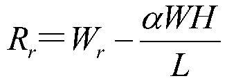 其中:R f为动态前轴轴荷,R r为动态后轴荷,α为制动减速度,W为整车重量;制动过程中相对于静止时的重量,产生了αWH/L的载荷转移;通过受力分析预估前后轴抱死所需制动力矩,通过制动器参数,计算得到抱死压力,完成整车制动抱死压力评估。
 - 如权利要求1所述的一种考虑主动制动功能的制动系统匹配分析方法,其特征在于,所述步骤S2具体包括:在Amesim中搭建制动系统液压模型,其中进油泵为柱塞泵,由电机带动偏心轮来驱动柱塞泵,柱塞在轴线方向的位移为:
 其中:s为柱塞在轴线方向的位移,r为偏心轮半径,e为偏心轮偏心量,θ为偏心轮转动角度;泵的流量计算公式:
 其中:Q b为油泵输出流量,V b为油泵流量,S m为电机转速,P bin为油泵入口端压力,P bout为油泵出口端压力,a为油泵压力因子;电磁阀的流量计算:
 其中:Q为液压介质流量,C qmax为最大流量系数,ρ为液压液密度,ΔP为电磁阀两端压力差,A为节流孔截面积,λe为液压介质流动雷诺数,χ为节流孔湿周长度,η为液压介质动力粘度;制动管路的流量计算:
 其中:P P为管路中液压,t为时间,E PF为制动液和管路的有效体积模量,A P为管路的横截面积,Q P为管路中流量,x p为管路长度。
 - 如权利要求1所述的一种考虑主动制动功能的制动系统匹配分析方法,其特征在于,所述步骤S3具体包括:在实车上断开软管与硬管连接处,将制动钳和软管保证实车连接状态接入台架实测制动器及软管所需液量数据,通过对步骤S2中的电磁阀流量积分得到所需制动液液量,再对以上前后制动器所需制动液液量map插值得到压力值,实现制动器轮缸压力计算。
- 一种制动系统匹配分析系统,其特征在于,包括:抱死压力评估模块,用于根据整车参数、轮胎滚动半径和制动减速度来得到制动抱死压力;动力源模块,用于由电机转速、偏心轮和柱塞位移来计算得到泵的流量;传输介质模块,用于评估流经电磁阀和硬管内制动液流量;液压源模块,用于评估ESC主动增压时吸入制动液液流量;负载模块,用于通过制动器所需液量获得建立的轮缸压力。
- 如权利要求5所述的一种制动系统匹配分析系统,其特征在于,在所述抱死压力评估模块中,使用Python搭建用于人机交互的用户界面。
Applications Claiming Priority (2)
| Application Number | Priority Date | Filing Date | Title |
|---|---|---|---|
| CN202010688985.7 | 2020-07-15 | ||
| CN202010688985.7A CN111923883B (zh) | 2020-07-15 | 2020-07-15 | 一种考虑主动制动功能的制动系统匹配分析方法和系统 |
Publications (1)
| Publication Number | Publication Date |
|---|---|
| WO2022011993A1 true WO2022011993A1 (zh) | 2022-01-20 |
Family
ID=73313490
Family Applications (1)
| Application Number | Title | Priority Date | Filing Date |
|---|---|---|---|
| PCT/CN2020/141896 Ceased WO2022011993A1 (zh) | 2020-07-15 | 2020-12-31 | 一种考虑主动制动功能的制动系统匹配分析方法和系统 |
Country Status (2)
| Country | Link |
|---|---|
| CN (1) | CN111923883B (zh) |
| WO (1) | WO2022011993A1 (zh) |
Cited By (6)
| Publication number | Priority date | Publication date | Assignee | Title |
|---|---|---|---|---|
| CN114312700A (zh) * | 2022-03-04 | 2022-04-12 | 万向钱潮股份有限公司 | 一种多轴商用车线控制动系统防抱死压力协调控制方法 |
| CN115061445A (zh) * | 2022-03-25 | 2022-09-16 | 温州立晨汽车零部件有限公司 | 一种汽车esc主动建压能力的测试装置及方法 |
| CN115270463A (zh) * | 2022-07-27 | 2022-11-01 | 北京电子科技职业学院 | 一种汽车制动系统性能仿真分析方法 |
| CN116101239A (zh) * | 2022-12-23 | 2023-05-12 | 吉林大学 | 一种基于集成式线控制动系统的汽车制动防抱死控制方法 |
| CN117804584A (zh) * | 2023-12-28 | 2024-04-02 | 中国重汽集团济南动力有限公司 | 一种商用车动态载荷采集及数据处理系统及方法 |
| CN120974855A (zh) * | 2025-10-21 | 2025-11-18 | 浙江万安科技股份有限公司 | 一种制动脚感分析方法及系统 |
Families Citing this family (5)
| Publication number | Priority date | Publication date | Assignee | Title |
|---|---|---|---|---|
| CN111923883B (zh) * | 2020-07-15 | 2022-11-11 | 中国第一汽车股份有限公司 | 一种考虑主动制动功能的制动系统匹配分析方法和系统 |
| CN112857827B (zh) * | 2021-01-13 | 2022-06-17 | 中国第一汽车股份有限公司 | 一种汽车制动距离测试及计算方法 |
| CN116811821B (zh) * | 2022-03-21 | 2026-07-14 | 上汽通用汽车有限公司 | 驾驶员制动行为优先的判断方法、装置以及驾驶辅助系统 |
| CN118025094B (zh) * | 2024-01-02 | 2025-10-10 | 中国第一汽车股份有限公司 | 一种机械主缸的需求排液量计算方法、装置、系统和介质 |
| CN119189946B (zh) * | 2024-11-26 | 2025-02-18 | 中国第一汽车股份有限公司 | 冗余制动系统的校核计算方法、装置、系统及介质 |
Citations (3)
| Publication number | Priority date | Publication date | Assignee | Title |
|---|---|---|---|---|
| JP2002139393A (ja) * | 2000-11-06 | 2002-05-17 | Toyota Central Res & Dev Lab Inc | 圧力推定装置、圧力制御装置及び方法 |
| CN104143011A (zh) * | 2013-05-09 | 2014-11-12 | 广州汽车集团股份有限公司 | 制动系统匹配分析方法和系统 |
| CN111923883A (zh) * | 2020-07-15 | 2020-11-13 | 中国第一汽车股份有限公司 | 一种考虑主动制动功能的制动系统匹配分析方法和系统 |
Family Cites Families (20)
| Publication number | Priority date | Publication date | Assignee | Title |
|---|---|---|---|---|
| JPH0288350A (ja) * | 1988-09-24 | 1990-03-28 | Sumitomo Electric Ind Ltd | アンチロック用流量制御弁 |
| JPH03246157A (ja) * | 1990-02-23 | 1991-11-01 | Toyota Motor Corp | アンチスキッド制御装置 |
| DE4338065C2 (de) * | 1993-11-08 | 1995-08-10 | Daimler Benz Ag | Verfahren zur Durchführung eines automatischen Bremsvorgangs für Kraftfahrzeuge mit einem Antiblockiersystems |
| JP3699211B2 (ja) * | 1996-09-04 | 2005-09-28 | 日信工業株式会社 | 車両用アンチロックブレーキ制御装置 |
| DE19648596A1 (de) * | 1996-11-23 | 1998-05-28 | Teves Gmbh Alfred | Vefahren zum Betreiben einer blockiergeschützten Kraftfahrzeugbremnsanlage |
| CN1295952A (zh) * | 2000-11-03 | 2001-05-23 | 华南理工大学 | 汽车防抱制动系统参考车速确定方法及其制动控制程序 |
| US7010411B2 (en) * | 2003-07-21 | 2006-03-07 | Delphi Technologies, Inc. | Rear pressure control and dynamic rear proportioning in a vehicle brake system |
| JP4946985B2 (ja) * | 2008-06-25 | 2012-06-06 | トヨタ自動車株式会社 | ブレーキ制御装置 |
| CN102167020B (zh) * | 2011-03-29 | 2016-08-03 | 奇瑞汽车股份有限公司 | 一种基于线控制动系统的制动力的调节方法 |
| KR20140104260A (ko) * | 2013-02-20 | 2014-08-28 | 주식회사 만도 | 차량용 브레이크 시스템 |
| CN105228870B (zh) * | 2013-05-21 | 2017-07-11 | 丰田自动车株式会社 | 制动装置 |
| DE102013217579B4 (de) * | 2013-09-04 | 2025-09-11 | Robert Bosch Gmbh | Verfahren zum Betreiben eines elektromechanischen Bremskraftverstärkers eines Bremssystems, Verfahren zum Betreiben eines rekuperativen Bremssystems und Steuervorrichtung für zumindest einen elektromechanischen Bremskraftverstärker eines Bremssystems |
| CN104149765B (zh) * | 2014-08-19 | 2017-01-25 | 清华大学 | 一种可实现分时控制的汽车电子液压制动系统 |
| CN104742888B (zh) * | 2015-02-06 | 2017-03-29 | 中国第一汽车股份有限公司 | 全驱车辆参考车速实时检测方法 |
| CN105109472A (zh) * | 2015-08-21 | 2015-12-02 | 奇瑞汽车股份有限公司 | 一种轮缸液压制动力的估算方法及装置 |
| CN106184168B (zh) * | 2016-07-29 | 2019-02-05 | 天津英创汇智汽车技术有限公司 | 一种汽车制动系统及制动压力控制方法 |
| CN107697052B (zh) * | 2017-09-05 | 2019-12-31 | 中国第一汽车股份有限公司 | 一种商用车空气处理单元控制方法 |
| CN109552295B (zh) * | 2017-09-25 | 2021-05-04 | 现代摩比斯株式会社 | 用于控制制动系统的电磁阀电流的设备和方法 |
| CN209800385U (zh) * | 2019-02-11 | 2019-12-17 | 北京亿美博科技有限公司 | 一种数字液压变量泵 |
| CN110816284B (zh) * | 2019-10-24 | 2022-09-16 | 江苏大学 | 一种车辆复合制动器制动力矩的分配方法 |
-
2020
- 2020-07-15 CN CN202010688985.7A patent/CN111923883B/zh active Active
- 2020-12-31 WO PCT/CN2020/141896 patent/WO2022011993A1/zh not_active Ceased
Patent Citations (3)
| Publication number | Priority date | Publication date | Assignee | Title |
|---|---|---|---|---|
| JP2002139393A (ja) * | 2000-11-06 | 2002-05-17 | Toyota Central Res & Dev Lab Inc | 圧力推定装置、圧力制御装置及び方法 |
| CN104143011A (zh) * | 2013-05-09 | 2014-11-12 | 广州汽车集团股份有限公司 | 制动系统匹配分析方法和系统 |
| CN111923883A (zh) * | 2020-07-15 | 2020-11-13 | 中国第一汽车股份有限公司 | 一种考虑主动制动功能的制动系统匹配分析方法和系统 |
Non-Patent Citations (2)
| Title |
|---|
| JIANG SHUAI: "Matching and Evaluation of Braking System for an Electric Car", MASTER THESIS, TIANJIN POLYTECHNIC UNIVERSITY, CN, no. 3, 15 March 2020 (2020-03-15), CN , XP055887102, ISSN: 1674-0246 * |
| QI XUELE, SONG JIAN,WANG HUI-YI,LI LIANG: "Modeling and Analysis of Vehicle ESP Hydraulic Control Device Using AMESim", MACHINE TOOL & HYDRAULICS, no. 8, 31 August 2005 (2005-08-31), XP055887105, ISSN: 1001-3881 * |
Cited By (7)
| Publication number | Priority date | Publication date | Assignee | Title |
|---|---|---|---|---|
| CN114312700A (zh) * | 2022-03-04 | 2022-04-12 | 万向钱潮股份有限公司 | 一种多轴商用车线控制动系统防抱死压力协调控制方法 |
| CN115061445A (zh) * | 2022-03-25 | 2022-09-16 | 温州立晨汽车零部件有限公司 | 一种汽车esc主动建压能力的测试装置及方法 |
| CN115061445B (zh) * | 2022-03-25 | 2024-11-19 | 温州立晨汽车零部件有限公司 | 一种汽车esc主动建压能力的测试装置及方法 |
| CN115270463A (zh) * | 2022-07-27 | 2022-11-01 | 北京电子科技职业学院 | 一种汽车制动系统性能仿真分析方法 |
| CN116101239A (zh) * | 2022-12-23 | 2023-05-12 | 吉林大学 | 一种基于集成式线控制动系统的汽车制动防抱死控制方法 |
| CN117804584A (zh) * | 2023-12-28 | 2024-04-02 | 中国重汽集团济南动力有限公司 | 一种商用车动态载荷采集及数据处理系统及方法 |
| CN120974855A (zh) * | 2025-10-21 | 2025-11-18 | 浙江万安科技股份有限公司 | 一种制动脚感分析方法及系统 |
Also Published As
| Publication number | Publication date |
|---|---|
| CN111923883A (zh) | 2020-11-13 |
| CN111923883B (zh) | 2022-11-11 |
Similar Documents
| Publication | Publication Date | Title |
|---|---|---|
| CN111923883B (zh) | 一种考虑主动制动功能的制动系统匹配分析方法和系统 | |
| CN104340194B (zh) | 电控式制动系统的泵单元 | |
| CN104828043B (zh) | 制动系统和用于控制制动系统的方法 | |
| CN108032848B (zh) | 一种制动能量回收装置及其控制方法 | |
| US8075066B2 (en) | Metering check valve for active brake pads retraction system | |
| CN204567653U (zh) | 一种电子液压制动系统 | |
| CN105946837A (zh) | 一种具有多工作模式的电子液压制动系统 | |
| CN108189824A (zh) | 一种前轮ehb后轮emb的混合线控制动系统 | |
| CN108216174B (zh) | 一种冗余式双重主动增压制动系统 | |
| US9434365B2 (en) | Vehicle brake hydraulic pressure controller | |
| CN106564486A (zh) | 一种基于混合动力的全液压abs制动系统及其制动方法 | |
| CN104097623A (zh) | 一种车辆集成电液制动系统 | |
| CN104442767B (zh) | 具有能量回馈和esp功能的液压制动系统及其控制方法 | |
| CN110774900A (zh) | 用于轮毂电机驱动汽车全解耦式再生制动装置及控制方法 | |
| CN106347335A (zh) | 一种用于车辆的助力系统 | |
| CN205498924U (zh) | 一种液压寸进制动系统 | |
| CN108087346B (zh) | 一种轮毂马达液压驱动系统蓄能器流量控制方法 | |
| CN205890860U (zh) | 一种电动汽车电液复合制动系统 | |
| CN117325832B (zh) | 一种制动液压力泄除方法及电子液压制动系统 | |
| CN116901717A (zh) | 车辆制动回馈扭矩补偿方法、系统及车辆 | |
| CN205632469U (zh) | 一种多功能的汽车控制系统 | |
| CN207617703U (zh) | 一种环卫车转向、制动用电动双联油泵系统 | |
| CN118323082A (zh) | 一种商用车集成化线控制动控制系统及方法 | |
| CN110861504A (zh) | 一种汽车制动能量回收装置及其控制方法 | |
| CN116279351A (zh) | 乘用车制动系统匹配设计方法 |
Legal Events
| Date | Code | Title | Description |
|---|---|---|---|
| 121 | Ep: the epo has been informed by wipo that ep was designated in this application |
Ref document number: 20945124 Country of ref document: EP Kind code of ref document: A1 |
|
| NENP | Non-entry into the national phase |
Ref country code: DE |
|
| 122 | Ep: pct application non-entry in european phase |
Ref document number: 20945124 Country of ref document: EP Kind code of ref document: A1 |