WO2022009534A1 - カメラシステムの製造方法及びカメラシステム - Google Patents
カメラシステムの製造方法及びカメラシステム Download PDFInfo
- Publication number
- WO2022009534A1 WO2022009534A1 PCT/JP2021/019272 JP2021019272W WO2022009534A1 WO 2022009534 A1 WO2022009534 A1 WO 2022009534A1 JP 2021019272 W JP2021019272 W JP 2021019272W WO 2022009534 A1 WO2022009534 A1 WO 2022009534A1
- Authority
- WO
- WIPO (PCT)
- Prior art keywords
- camera
- vehicle
- camera system
- cover
- image
- Prior art date
- Legal status (The legal status is an assumption and is not a legal conclusion. Google has not performed a legal analysis and makes no representation as to the accuracy of the status listed.)
- Ceased
Links
Images



Classifications
-
- H—ELECTRICITY
- H04—ELECTRIC COMMUNICATION TECHNIQUE
- H04N—PICTORIAL COMMUNICATION, e.g. TELEVISION
- H04N23/00—Cameras or camera modules comprising electronic image sensors; Control thereof
- H04N23/57—Mechanical or electrical details of cameras or camera modules specially adapted for being embedded in other devices
-
- H—ELECTRICITY
- H04—ELECTRIC COMMUNICATION TECHNIQUE
- H04N—PICTORIAL COMMUNICATION, e.g. TELEVISION
- H04N17/00—Diagnosis, testing or measuring for television systems or their details
- H04N17/002—Diagnosis, testing or measuring for television systems or their details for television cameras
-
- G—PHYSICS
- G03—PHOTOGRAPHY; CINEMATOGRAPHY; ANALOGOUS TECHNIQUES USING WAVES OTHER THAN OPTICAL WAVES; ELECTROGRAPHY; HOLOGRAPHY
- G03B—APPARATUS OR ARRANGEMENTS FOR TAKING PHOTOGRAPHS OR FOR PROJECTING OR VIEWING THEM; APPARATUS OR ARRANGEMENTS EMPLOYING ANALOGOUS TECHNIQUES USING WAVES OTHER THAN OPTICAL WAVES; ACCESSORIES THEREFOR
- G03B17/00—Details of cameras or camera bodies; Accessories therefor
- G03B17/02—Bodies
- G03B17/08—Waterproof bodies or housings
-
- G—PHYSICS
- G03—PHOTOGRAPHY; CINEMATOGRAPHY; ANALOGOUS TECHNIQUES USING WAVES OTHER THAN OPTICAL WAVES; ELECTROGRAPHY; HOLOGRAPHY
- G03B—APPARATUS OR ARRANGEMENTS FOR TAKING PHOTOGRAPHS OR FOR PROJECTING OR VIEWING THEM; APPARATUS OR ARRANGEMENTS EMPLOYING ANALOGOUS TECHNIQUES USING WAVES OTHER THAN OPTICAL WAVES; ACCESSORIES THEREFOR
- G03B35/00—Stereoscopic photography
- G03B35/08—Stereoscopic photography by simultaneous recording
-
- H—ELECTRICITY
- H04—ELECTRIC COMMUNICATION TECHNIQUE
- H04N—PICTORIAL COMMUNICATION, e.g. TELEVISION
- H04N13/00—Stereoscopic video systems; Multi-view video systems; Details thereof
- H04N13/20—Image signal generators
- H04N13/204—Image signal generators using stereoscopic image cameras
- H04N13/239—Image signal generators using stereoscopic image cameras using two two-dimensional [2D] image sensors having a relative position equal to or related to the interocular distance
-
- H—ELECTRICITY
- H04—ELECTRIC COMMUNICATION TECHNIQUE
- H04N—PICTORIAL COMMUNICATION, e.g. TELEVISION
- H04N23/00—Cameras or camera modules comprising electronic image sensors; Control thereof
- H04N23/50—Constructional details
- H04N23/55—Optical parts specially adapted for electronic image sensors; Mounting thereof
-
- G—PHYSICS
- G03—PHOTOGRAPHY; CINEMATOGRAPHY; ANALOGOUS TECHNIQUES USING WAVES OTHER THAN OPTICAL WAVES; ELECTROGRAPHY; HOLOGRAPHY
- G03B—APPARATUS OR ARRANGEMENTS FOR TAKING PHOTOGRAPHS OR FOR PROJECTING OR VIEWING THEM; APPARATUS OR ARRANGEMENTS EMPLOYING ANALOGOUS TECHNIQUES USING WAVES OTHER THAN OPTICAL WAVES; ACCESSORIES THEREFOR
- G03B30/00—Camera modules comprising integrated lens units and imaging units, specially adapted for being embedded in other devices, e.g. mobile phones or vehicles
-
- G—PHYSICS
- G03—PHOTOGRAPHY; CINEMATOGRAPHY; ANALOGOUS TECHNIQUES USING WAVES OTHER THAN OPTICAL WAVES; ELECTROGRAPHY; HOLOGRAPHY
- G03B—APPARATUS OR ARRANGEMENTS FOR TAKING PHOTOGRAPHS OR FOR PROJECTING OR VIEWING THEM; APPARATUS OR ARRANGEMENTS EMPLOYING ANALOGOUS TECHNIQUES USING WAVES OTHER THAN OPTICAL WAVES; ACCESSORIES THEREFOR
- G03B43/00—Testing correct operation of photographic apparatus or parts thereof
Definitions
- the present invention relates to a method for manufacturing a camera system and a camera system.
- sensors mounted on the vehicle that monitor the surrounding area measure the distance and direction of the object, and if there is a possibility of collision with the object, a warning is given to the driver. Activate the automatic emergency brake.
- Sensors that monitor the surroundings of the vehicle include millimeter-wave radars, laser radars, cameras, and the like. Such a sensor is used not only for avoiding a collision with an object but also as a device for grasping the surrounding situation for automatic driving.
- the camera which is one of the sensors that monitor the surroundings of the vehicle, may have a large error in the measured distance, etc., or may not be able to detect an object properly if raindrops or dirt adhere to the lens during rainfall. Adhesion of raindrops and dirt to the lens can affect the safety of the vehicle while driving. Normally, the camera is mounted inside the vehicle interior, and the front of the camera is often covered with a windshield.
- Patent Document 1 describes a preview sensor that is attached to the front end of a roof rail attached to the roof of a vehicle body and acquires an image of the situation in front of the vehicle.
- the preview sensor described in Patent Document 1 detects a deviation in the mounting position of the preview sensor based on an image captured by a pair of light emitting sources mounted on the left and right tip portions of the vehicle body in front of the vehicle.
- an image conversion process is performed on the captured image so that the detected deviation becomes small.
- the preview sensor described in Patent Document 1 can sequentially correct the direction of the optical axis of the preview sensor based on the captured image of the light emitting source pair attached to the tip of the vehicle body, but is provided in front of the preview sensor. No consideration is given to the distortion of the image caused by the created window.
- the preview sensor described in Patent Document 1 when distortion of an image or the like varies due to variation of a transparent body provided in front of a camera such as a windshield or a window, it is difficult to stably correct the distortion of the image.
- the present invention has been made in view of the above, and an object of the present invention is to realize a camera system capable of stably acquiring an appropriate image in which image distortion and the like are corrected.
- a method for manufacturing a camera system includes a camera mounted on a vehicle and acquiring an image of the surroundings of the vehicle, a transparent cover covering the front of the camera, and the camera.
- a method of manufacturing a camera system provided in front of the camera which includes a restricting member for switching between passing and blocking incident light to the camera, wherein the cover is attached to the front of the camera and the cover is attached. It is characterized by including a step of performing calibration for correcting distortion of the image acquired by the camera, and a step of attaching the calibrated camera and the cover to the vehicle.
- FIG. 2 is a side view of the camera system shown in FIG. It is a figure explaining the example which provided the light-shielding plate instead of the light control member shown in FIG.
- FIG. 1 is a diagram illustrating a camera system of a comparative example.
- FIG. 1 is a view of the camera system of the comparative example from above the vehicle.
- Sensors that monitor the surroundings of the vehicle include millimeter-wave radar, laser radar, and cameras.
- Cameras that are one of the sensors that monitor the periphery of the vehicle include a monocular camera and a stereo camera C.
- the camera system of the comparative example shown in FIG. 1 is configured by a stereo camera C.
- the stereo camera C is installed in the passenger compartment of the vehicle, and the front of the stereo camera C is covered with the windshield W.
- the stereo camera C is composed of a left camera LC and a right camera RC arranged along the left-right direction of the vehicle at intervals from each other.
- the left camera LC and the right camera RC simultaneously capture the same object and acquire a pair of images.
- the stereo camera C measures the distance and direction to the object by using the parallax caused by the difference in the viewpoint position with respect to the same object reflected in the overlapping region of the pair of acquired images.
- the stereo camera C acquires an image through the windshield W.
- the front of the stereo camera C is the direction in which the lenses of the left camera LC and the right camera RC constituting the stereo camera C face.
- the image acquired through the windshield W has a larger distortion and pixel misalignment than the image acquired without the windshield W.
- the direction and amount of image distortion and pixel misalignment acquired through the windshield W depend on the shape of the windshield W.
- the windshield W is simplified and drawn into an easy-to-understand shape.
- the shape of the windshield W differs depending on the type of vehicle to which it is attached, and is a three-dimensional shape having a three-dimensional curved surface.
- the shape of the windshield W tends to vary from windshield W to windshield W.
- the distortion of the image acquired through the windshield W tends to vary from windshield W to windshield W.
- an error such as a measured distance becomes large.
- the incident light L to the left camera LC passes through the left transmission portion W1 of the windshield W and is incident on the left camera LC.
- the incident light L on the right camera RC passes through the right transmission portion W2 of the windshield W and is incident on the right camera RC. That is, the left transparent portion W1 and the right transparent portion W2 are different portions.
- the distortion and the like of the image acquired by the left camera LC and the distortion and the like of the image acquired by the right camera RC are different in their generation direction and amount.
- the stereo camera C the distance from the parallax of the pair of images acquired by the left camera LC and the right camera RC to the object is measured.
- the error such as the measured distance becomes larger.
- the shape of the windshield W is a three-dimensional shape having a three-dimensional curved surface, if the angle of view of the stereo camera C is widened to 90 degrees or more, the distortion aberration becomes larger and the acquired image is obtained. Distortion and the like become larger, and more easily varies.
- the distance measured based on the image acquired by the stereo camera C is corrected by using the correction value. If the distortion or the like of the image acquired through the windshield W varies from windshield W to windshield W, it is difficult to easily correct the measured distance or the like by using a uniform correction value. In particular, when the stereo camera C has a wide angle of view, the distortion of the image becomes larger and the image becomes more likely to vary, so that it becomes more difficult to correct using a uniform correction value. Therefore, how to stably correct the distortion of the image that is scattered by the windshield W is important in appropriately measuring the distance to the object.
- the stereo camera C is equipped with a CMOS image sensor and the like. Since the image sensor is configured to include a photodiode, an electromotive force may be generated by photoelectric conversion when the incident light L is incident. When the power of the stereo camera C is off, the protection circuit of the image sensor does not operate, and this electromotive force may cause a current to flow into the power circuit of the image sensor to affect the circuit. In particular, when the image sensor has a high pixel count, this electromotive force becomes so large that it cannot be ignored, and a relatively large current flows into the power supply circuit of the image sensor, which has a great effect on the circuit. May interfere.
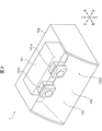
- FIG. 2 is a diagram schematically showing the appearance of the camera system 1 of the present embodiment.
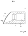
- FIG. 3 is a side view of the camera system 1 shown in FIG. In FIG. 2, the internal structure of the case 102 for fixing the stereo camera 101 is not shown, and the upper surface of the case 102 made of a non-transparent body is transparently shown. In FIG. 3, the side surface portion of the case 102 is not shown.
- FIG. 3 shows a state in which the transmittance of the dimming member 104 is reduced.
- the camera system 1 is a sensor system mounted on a vehicle and monitoring an object such as a vehicle, a pedestrian, or a bicycle existing around the vehicle.
- the camera provided in the camera system 1 may be a monocular camera or a stereo camera. In the present embodiment, the camera provided in the camera system 1 will be described as a stereo camera 101.
- the camera system 1 includes a stereo camera 101 that acquires an image of the surroundings of the vehicle, a case 102 that houses the stereo camera 101, a transparent cover 103 that covers the front of the stereo camera 101, and a dimming member that can change the transmission rate. It is equipped with 104.
- the stereo camera 101 has the same configuration as the stereo camera C.
- the stereo camera 101 is composed of a left camera 101a and a right camera 101b arranged along the left-right direction of the vehicle at intervals from each other.
- the left camera 101a and the right camera 101b simultaneously capture the same object and acquire a pair of images.
- the stereo camera 101 measures the distance, orientation, and the like to the object by using the parallax caused by the difference in the viewpoint position with respect to the same object reflected in the overlapping region of the pair of acquired images. That is, the stereo camera 101 acquires a pair of images having parallax.
- the case 102 has a rectangular parallelepiped shape and is arranged so that the longitudinal direction is along the left-right direction of the vehicle.
- An opening 102a is provided in the front portion of the case 102.
- the opening 102a faces the front of the stereo camera 101 housed in the case 102. That is, the case 102 is provided with an opening 102a in front of the housed stereo camera 101.
- the cover 103 is made of a resin plate such as polycarbonate or acrylic or a transparent body such as a glass plate.
- the cover 103 is attached to the opening 102a of the case 102.
- the cover 103 is integrally formed with the case 102.
- the cover 103 covers the front of the stereo camera 101 and prevents raindrops, dirt, and the like from adhering to the lens of the stereo camera 101.
- the cover 103 can be formed by uniformly adopting a shape having a smaller area than the windshield W and having no three-dimensional curved surface regardless of the vehicle type of the vehicle on which the cover 103 is mounted. Therefore, the variation in the shape of the cover 103 is much smaller than that of the windshield W.
- the shape of the cover 103 may be, for example, a flat plate or a semi-cylindrical shape.
- the dimming member 104 is a member whose transmittance can be changed.
- the dimming member 104 is provided in front of the stereo camera 101 housed in the case 102, and switches the passing and blocking of the incident light to the stereo camera 101 based on the on / off of the power of the stereo camera 101 to switch the incident light. Consists of regulatory members to regulate.
- the dimming member 104 includes a dimming film and a drive circuit unit.
- the dimming film of the dimming member 104 increases the transmittance by supplying electric power to allow the incident light to pass through, and decreases the transmittance by stopping the supply of electric power to block the incident light.
- the light control film is composed of, for example, a light control film containing oriented particles oriented in the electric field direction by applying a voltage.
- the photochromic film containing the oriented particles for example, LCF-1103DHA manufactured by Hitachi Kasei Co., Ltd. can be adopted, but the film is not limited thereto.
- the light control film may be composed of a light control film including a liquid crystal display.
- the drive circuit unit of the dimming member 104 is connected to the power supply of the stereo camera 101.
- the power supply of the stereo camera 101 is switched on and off in conjunction with the ignition power supply of the vehicle.
- the drive circuit unit supplies power to the light control film when the power of the stereo camera 101 is on, and stops power supply to the light control film when the power of the stereo camera 101 is off.
- the drive circuit unit passes the incident light to the stereo camera 101 by increasing the transmittance of the photochromic film when the power of the stereo camera 101 is turned on.
- the drive circuit unit blocks the incident light on the stereo camera 101 by reducing the transmittance of the photochromic film.
- the dimming member 104 prevents the electromotive force from being generated by the incident light on the stereo camera 101 when the power of the stereo camera 101 is turned off.
- the dimming member 104 is provided on the cover 103.
- the light control member 104 may be provided on the cover 103 by sandwiching the light control film between a pair of transparent bodies constituting the cover 103.
- the dimming member 104 may be provided on the cover 103 by attaching a dimming film to the inner surface or the outer surface of the transparent body constituting the cover 103.
- FIG. 4 is a diagram illustrating an example in which a light-shielding plate 105 is provided instead of the dimming member 104 shown in FIG.
- the camera system 1 may be provided with a light-shielding plate 105 instead of the dimming member 104.
- the light-shielding plate 105 is provided in front of the stereo camera 101 housed in the case 102, and regulates the incident light by switching between passing and blocking the incident light to the stereo camera 101 based on the on / off of the power of the stereo camera 101. Consists of regulatory members.
- the shading plate 105 is held by a holding mechanism 105a arranged between the lens of the stereo camera 101 and the cover 103.
- the holding mechanism 105a holds the light-shielding plate 105 between the lens of the stereo camera 101 and the cover 103 so that the light-shielding plate 105 is orthogonal to the optical axis of the stereo camera 101.
- the holding mechanism 105a is movable in a direction intersecting the optical axis of the stereo camera 101.
- the holding mechanism 105a reciprocates the light-shielding plate 105 between a position on the path of the incident light to the stereo camera 101 and a position deviating from the path.
- the holding mechanism 105a is connected to the power supply of the stereo camera 101.
- the holding mechanism 105a When the power of the stereo camera 101 is turned off, the holding mechanism 105a holds the shading plate 105 at a position on the path. When the power of the stereo camera 101 is turned on, the holding mechanism 105a moves the light-shielding plate 105 to a position off the path. The light-shielding plate 105 prevents the electromotive force from being generated by the incident light on the stereo camera 101 when the power of the stereo camera 101 is turned off.
- FIG. 5 is a diagram illustrating an example of mounting the camera system 1 shown in FIG. 3 to a vehicle.
- FIG. 5 shows an example in which the camera system 1 shown in FIG. 3 is attached to a vehicle, and shows a state in which the transmittance of the dimming member 104 is reduced.
- the camera system 1 When the vehicle is a four-wheeled vehicle, the camera system 1 is attached to the outside of the vehicle interior such as the roof portion R of the vehicle. When the vehicle is a two-wheeled vehicle, the camera system 1 is attached to the front part of the vehicle. In these cases, the camera system 1 is attached so that the front of the stereo camera 101 faces the front of the vehicle. However, in the camera system 1, a plurality of camera systems 1 may be attached to the vehicle. When a plurality of camera systems 1 are attached to a vehicle, the front of each stereo camera 101 is attached so as to face not only the front of the vehicle but also the rear of the vehicle and the side of the vehicle.
- the camera system 1 may be attached by fitting the cover 103 into the hole W3.
- the hole W3 has a shape that matches the shape of the cover 103, and may be provided on the upper portion of the windshield W adjacent to the roof portion R.
- the camera system 1 of the present embodiment includes a camera (stereo camera 101 or monocular camera) mounted on the vehicle and acquiring an image of the periphery of the vehicle, and a cover 103 that covers the front of the camera.
- the camera system 1 includes a regulating member (dimming member 104 or shading plate 105) that switches between passing and blocking incident light to the camera based on the on / off of the power of the camera.
- the camera system 1 of the present embodiment can be attached to the vehicle without covering the front of the camera by the windshield W having a large variation in shape such as attachment to the outside of the vehicle interior.
- the camera system 1 of the present embodiment can acquire an image without going through a windshield W having a large variation in shape while preventing raindrops, dirt, and the like from adhering to the camera system 1.
- the camera system 1 of the present embodiment can prevent image distortion and the like caused by the windshield W from occurring. In the camera system 1 of the present embodiment, only the distortion of the image caused by the lens and the cover 103 of the camera whose shape variation is much smaller than that of the windshield W occurs, so that the distortion of the acquired image can be easily eliminated. Moreover, it can be corrected stably.
- the camera system 1 of the present embodiment can regulate the incident light to the camera when the power of the camera is turned off, it is possible to prevent the above-mentioned electromotive force from being generated in the image sensor. Since the camera system 1 of the present embodiment can prevent the current from flowing into the power supply circuit of the image sensor due to the electromotive force and affecting the circuit, the reliability of the camera system 1 can be improved. , The image can be acquired stably.
- the camera system 1 of the present embodiment can realize a camera system capable of stably acquiring an appropriate image obtained by easily and stably correcting image distortion and the like.
- the regulating member is composed of a dimming member 104 whose transmittance can be changed.
- the dimming member 104 is a dimming film that increases the transmittance by supplying electric power to allow incident light to pass through, and reduces the transmittance by stopping the supply of electric power to block the incident light, and when the power of the camera is turned on. It is provided with a drive circuit unit that supplies electric power to the dimming film and stops the supply of electric power to the dimming film when the power of the camera is turned off.
- the camera system 1 of the present embodiment increases the transmittance to pass the incident light when the power of the camera is turned on, and reduces the transmittance to block the incident light when the power of the camera is turned off. can do.
- the camera system 1 of the present embodiment quickly passes and blocks incident light as compared with the case where the regulatory member is configured by the light-shielding plate 105 that switches between transmission and blocking of incident light by the mechanical behavior of the holding mechanism 105a. Can be switched to.
- the camera system 1 of the present embodiment can surely prevent the above-mentioned electromotive force from being generated in the image sensor when the power of the camera is turned off. Therefore, the camera system 1 of the present embodiment can realize a camera system capable of more stably acquiring an appropriate image obtained by easily and stably correcting image distortion and the like.
- the dimming member 104 is provided on the cover 103.
- the camera system 1 of the present embodiment it is not necessary to arrange a component between the cover 103 and the camera as compared with the case where the regulating member is composed of the light-shielding plate 105, so that the camera to the cover 103 can be arranged.
- the distance can be shortened.
- the camera system 1 of the present embodiment can suppress image distortion and the like caused by refraction of incident light in the cover 103, and can also reduce the size of the camera system 1. Therefore, the camera system 1 of the present embodiment can realize a camera system capable of stably acquiring an appropriate image obtained by correcting image distortion and the like more easily and stably.
- the camera system 1 of the present embodiment is composed of a stereo camera 101 in which the camera acquires a pair of images having parallax.
- the distortion of the image acquired by the left camera 101a constituting the stereo camera 101 and the distortion of the image acquired by the right camera 101b are different in the direction and amount of occurrence.
- the distortion and the like of the images generated in the pair of images are larger and more variable, so that it is difficult to correct them.
- the camera system 1 of the present embodiment since the front surface of the stereo camera 101 is not covered by the windshield W, distortion and the like of the image acquired by the stereo camera 101 can be corrected relatively easily and stably. Therefore, the camera system 1 of the present embodiment can stably acquire an appropriate image obtained by easily and stably correcting image distortion and the like even when the camera is configured by the stereo camera 101. A possible camera system can be realized.
- the cover 103 is fitted into the hole W3 provided in the windshield W of the vehicle and attached to the vehicle.
- the camera system 1 of the present embodiment is installed in the vehicle interior without the front of the camera being covered by the windshield W. Since the camera system 1 of the present embodiment does not have to be attached to the roof portion R or the like of the vehicle, the roof portion R or the like can be used for other purposes and the air resistance of the vehicle can be reduced. It is possible to improve the running performance and fuel efficiency of the vehicle.
- FIG. 6 is a flowchart showing a manufacturing method of a camera system of a comparative example.
- steps S201 to S203 are steps performed by the camera maker
- steps S204 to S206 are steps performed by the vehicle maker.
- the camera assembly process (S201) for assembling the stereo camera C constituting the camera system of the comparative example is performed.
- a calibration step (S202) for correcting distortion and the like of the image acquired by the stereo camera C is performed.
- a chart calibration target
- a chart is a board on which a predetermined pattern, such as a checker pattern, in which predetermined figures are repeated at predetermined intervals is printed.
- the calibration step (S202) parallelization processing for aligning the epopular lines of the pair of images acquired by the left camera LC and the right camera RC constituting the stereo camera C and the optical axis adjustment are performed.
- the parallelization process is not performed when the camera system is composed of a monocular camera.
- the inspection step (S203) is performed in the manufacturing method of the camera system of the comparative example.
- the stereo camera C that has passed the inspection step (S203) is shipped from the camera manufacturer to the vehicle manufacturer.
- a vehicle mounting step (S204) for attaching the stereo camera C to the vehicle is performed.
- the stereo camera C is mounted in the vehicle interior of the vehicle.
- the front of the stereo camera C is covered with the windshield W.
- a cover mounting step (S205) for mounting a transparent cover that covers the front of the stereo camera C is performed after the vehicle mounting step (S204).
- the aiming step (S206) is performed in the manufacturing method of the camera system of the comparative example.
- the optical axis of the stereo camera C is adjusted using the same chart as above.
- the vehicle mounting step (S204) or the cover mounting step (S205) that covers the front of the stereo camera C with the windshield W or the like is performed after the calibration step (S202). Will be done.
- the calibration step (S202) of the comparative example although the image distortion or the like caused by the stereo camera C can be corrected, the image distortion or the like caused by the windshield W or the like cannot be corrected.
- the aiming step (S206) performed after the vehicle mounting step (S204) or the cover mounting step (S205) the same work as the calibration step (S202) is performed again. It is conceivable to do.
- the above chart used in the calibration step (S202) needs to be a chart having a size such that a predetermined pattern such as a checker pattern is captured in the entire angle of view of the stereo camera C.
- a predetermined pattern such as a checker pattern
- the distance from the stereo camera C to the chart becomes long, so an enlarged chart is prepared. There must be.
- the horizontal angle of view of the stereo camera C is wide, it is not realistic because a huge chart that exceeds the vehicle width must be prepared.
- the stereo camera C is used in the above chart in the calibration step (S202).
- the aiming step (S206) is a step performed by the vehicle manufacturer. Vehicle manufacturers often perform the aiming process (S206) at the same time on the same production line as the optical axis adjustment of the headlights.
- the stereo camera C is positioned by moving the vehicle, but the optical axis of the headlight is adjusted. It is very difficult to position the vehicle with high accuracy on the same production line.
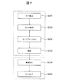
- FIG. 7 is a flowchart showing a manufacturing method of the camera system 1 of the present embodiment.
- the process S201, the process S205, the process S202 and the process S203 are performed by the camera maker, and the process S204 and the process S206 are performed by the vehicle maker.
- the camera assembly process (S201) for assembling the camera system 1 is performed.
- the stereo camera 101 is housed in the case 102.
- the restricting member for switching between passing and blocking the incident light to the stereo camera 101 is composed of the light-shielding plate 105
- the light-shielding plate 105 and the holding mechanism 105a are housed in the case 102 in the camera assembly step (S201).
- the regulating member for switching between passing and blocking the incident light to the stereo camera 101 is composed of the dimming member 104
- the dimming member 104 is provided in advance on the cover 103.
- a cover attachment step (S205) for attaching the cover 103 to the front of the stereo camera 101 is performed.
- the cover 103 is attached to the opening 102a of the case 102 in which the stereo camera 101 is housed.
- the calibration step (S202) is performed in the manufacturing method of the camera system 1.
- the calibration step (S202) of the present embodiment is a calibration step for correcting the distortion of the image acquired by the stereo camera 101 to which the cover 103 is attached. That is, in the calibration step (S202) of the present embodiment, not only the image distortion caused by the stereo camera 101 but also the image distortion caused by the cover 103 is taken into consideration.
- the above chart is photographed by the stereo camera 101 via the cover 103, and the image coordinates of the photographed image are acquired.
- a parameter that determines the correspondence between the acquired image coordinates and the spatial coordinates is obtained. According to the obtained parameters, the image with distortion or the like acquired by the stereo camera 101 via the cover 103 can be corrected to the image without distortion or the like.
- parallelization processing and optical axis adjustment are performed in the same manner as in the calibration step (S202) of the comparative example.
- the inspection step (S203) is performed in the manufacturing method of the camera system 1.
- the camera system 1 that has passed the inspection step (S203) is shipped from the camera manufacturer to the vehicle manufacturer.
- the vehicle mounting step (S204) of the present embodiment is a step of mounting the calibrated stereo camera 101 and the cover 103 to the vehicle. Specifically, in the vehicle mounting step (S204) of the present embodiment, the case 102 accommodating the stereo camera 101 in which the calibration step (S202) has been performed is mounted on, for example, the roof portion R of the vehicle.
- the cover 103 is provided with the hole W3. It is a process of attaching the stereo camera 101 and the cover 103 to the vehicle by fitting the cover 103 into the vehicle. Specifically, in this case, in the vehicle mounting step (S204) of the present embodiment, the cover 103 is fitted into the hole W3, and the case 102 accommodating the stereo camera 101 is mounted on the vehicle.
- the aiming step (S206) is performed in the manufacturing method of the camera system 1.
- the aiming step (S206) of the present embodiment is the same as the aiming step (S206) of the comparative example.
- the manufacturing method of the camera system 1 of the present embodiment is the manufacturing method of the camera system 1 having the above configuration, and is a step of attaching the cover 103 to the front of the camera (stereo camera 101 or monocular camera) (FIG. 7 S205) is included.
- the manufacturing method of the camera system 1 of the present embodiment includes a step of performing calibration for correcting distortion of an image acquired by a camera to which a cover 103 is attached (S202 of FIG. 7).
- the manufacturing method of the camera system 1 of the present embodiment includes a step of attaching the calibrated camera and the cover 103 to the vehicle (S204 of FIG. 7).
- the calibration step (S202) is performed in consideration of not only the image distortion caused by the camera but also the image distortion caused by the cover 103. Can be done.
- a member capable of causing image distortion or the like does not cover the front of the camera.
- the manufacturing method of the camera system 1 of the present embodiment can easily and stably correct distortion and the like of an image acquired by a camera.
- the manufacturing method of the camera system 1 of the present embodiment can block the incident light to the camera when the power of the camera is turned off, and can prevent the above electromotive force from being generated in the image sensor.
- System 1 can be manufactured.
- the manufacturing method of the camera system 1 of the present embodiment can prevent a current from flowing into the power supply circuit of the image sensor due to the electromotive force and affect the circuit, and can produce a highly reliable and stable image.
- the acquireable camera system 1 can be manufactured.
- the camera system 1 of the present embodiment can realize a camera system capable of stably acquiring an appropriate image obtained by easily and stably correcting image distortion and the like.
- the regulating member is composed of a dimming member 104 whose transmittance can be changed.
- the dimming member 104 is provided on the cover 103, and when the power of the camera is turned on, the transmittance is increased to allow the incident light to pass through, and when the power of the camera is turned off, the transmittance is decreased to block the incident light. do.
- the manufacturing method of the camera system 1 of the present embodiment can manufacture the camera system 1 capable of shortening the distance from the camera to the cover 103.
- the manufacturing method of the camera system 1 of the present embodiment can suppress image distortion and the like caused by refraction of incident light in the cover 103, and can also reduce the size of the camera.
- System 1 can be manufactured.
- the manufacturing method of the camera system 1 of the present embodiment can manufacture the camera system 1 capable of quickly switching between the passage and blocking of incident light.
- the method for manufacturing the camera system 1 of the present embodiment can manufacture the camera system 1 that can surely prevent the above-mentioned electromotive force from being generated in the image sensor when the power of the camera is turned off. Therefore, the manufacturing method of the camera system 1 of the present embodiment realizes a camera system capable of more stably acquiring an appropriate image obtained by correcting image distortion and the like more easily and stably. be able to.
- the camera is composed of a stereo camera 101 that acquires a pair of images having parallax.
- the front surface of the stereo camera 101 is not covered by the windshield W, distortion and the like of the image acquired by the stereo camera 101 can be corrected relatively easily and stably. Can be done. Therefore, in the manufacturing method of the camera system 1 of the present embodiment, even when the camera is configured by the stereo camera 101, an appropriate image obtained by easily and stably correcting image distortion and the like can be stably acquired. It is possible to realize a camera system that can be used.
- the step of attaching the camera and the cover 103 to the vehicle (S204). Fits the cover 103 into the hole W3 and attaches the camera and the cover 103 to the vehicle.
- the camera system 1 can be mounted in the vehicle interior without the front of the camera being covered by the windshield W.
- the roof portion R or the like can be used for other purposes and the air of the vehicle can be used. It is possible to manufacture a camera system 1 capable of reducing resistance and improving the running performance and fuel efficiency of a vehicle.
- a method of manufacturing a camera system 1 including a regulatory member for switching between passing and blocking incident light to the camera has been described. It is important that the calibration step (S202) is performed after the cover mounting step (S205) as the manufacturing method of the camera system 1, and the method can be applied to the camera system 1 not provided with the regulating member.
- the manufacturing method of the camera system 1 has been described with the cover 103 attached to the opening 102a of the case 102 as a separate member from the windshield W.
- the cover 103 may be regarded as one with the windshield W, and the windshield W may be attached to the opening 102a of the case 102 during the cover attachment step (S205) of FIG.
- calibration may be performed by a camera housed in a case 102 to which a windshield W is attached as a cover 103.
- the dimming member 104 is provided by attaching a dimming film to a part or all of the inner surface of the windshield W.
- the dimming member 104 is provided by sandwiching the dimming film in advance between the pair of glasses constituting the windshield W.
- the present invention is not limited to the above embodiment, and includes various modifications.
- the above-described embodiment has been described in detail in order to explain the present invention in an easy-to-understand manner, and is not necessarily limited to the one including all the described configurations.
- it is possible to replace a part of the configuration of one embodiment with the configuration of another embodiment and it is also possible to add the configuration of another embodiment to the configuration of one embodiment.
- each of the above configurations, functions, processing units, processing means, etc. may be realized by hardware by designing a part or all of them by, for example, an integrated circuit. Further, each of the above configurations, functions, and the like may be realized by software by the processor interpreting and executing a program that realizes each function. Information such as programs, tapes, and files that realize each function can be placed in a memory, a recording device such as a hard disk or SSD (solid state drive), or a recording medium such as an IC card, SD card, or DVD.
- a recording device such as a hard disk or SSD (solid state drive)
- a recording medium such as an IC card, SD card, or DVD.
- control lines and information lines indicate those that are considered necessary for explanation, and do not necessarily indicate all control lines and information lines in the product. In practice, it can be considered that almost all configurations are interconnected.
Landscapes
- Engineering & Computer Science (AREA)
- Multimedia (AREA)
- Signal Processing (AREA)
- Physics & Mathematics (AREA)
- General Physics & Mathematics (AREA)
- Biomedical Technology (AREA)
- Health & Medical Sciences (AREA)
- General Health & Medical Sciences (AREA)
- Studio Devices (AREA)
- Fittings On The Vehicle Exterior For Carrying Loads, And Devices For Holding Or Mounting Articles (AREA)
- Stereoscopic And Panoramic Photography (AREA)
- Blocking Light For Cameras (AREA)
- Testing, Inspecting, Measuring Of Stereoscopic Televisions And Televisions (AREA)
Abstract
本発明は、歪み等が補正された適切な画像を安定的に取得することが可能なカメラシステムを実現することを目的とする。カメラシステム1の製造方法は、車両に搭載され、車両の周辺の画像を取得するカメラと、カメラの前方を覆う透明なカバー103と、カメラの前方に設けられ、カメラへの入射光の通過と遮断とを切り替える規制部材とを備えるカメラシステム1の製造方法である。カメラシステム1の製造方法は、カメラの前方にカバー103を取り付ける工程(S205)と、カバー103が取り付けられたカメラによって取得された画像の歪みを補正するためのキャリブレーションを行う工程(S202)と、キャリブレーションが行われたカメラ及びカバー103を車両に取り付ける工程(S204)と、を含む。
Description
本発明は、カメラシステムの製造方法及びカメラシステムに関する。
車両の走行時の安全性を向上させるために、車両の周辺に存在する車両、歩行者又は自転車等の物体との衝突を回避するためのシステムが開発されている。この種のシステムでは、車両に搭載され周辺を監視するセンサによって当該物体との距離や方位等を計測し、当該物体との衝突の可能性がある場合には、ドライバに警告を報知したり、自動緊急ブレーキを作動させたりする。車両の周辺を監視するセンサとしては、ミリ波レーダ、レーザレーダ又はカメラ等がある。このようなセンサは、物体との衝突回避のみならず、自動運転のために周辺の状況を把握するデバイスとして利用される。
車両の周辺を監視するセンサの1つであるカメラは、降雨時の雨滴や汚れがレンズに付着すると、計測される距離等の誤差が大きくなったり、物体を適切に検知できなかったりする。雨滴や汚れがレンズに付着することは、車両の走行時の安全性に影響を及ぼす可能性がある。通常、カメラは、車両の車室内に取り付けられ、カメラの前方がウィンドシールドによって覆われることが多い。
ウィンドシールドによって前方を覆われたカメラでは、ウィンドシールドを介して画像を取得するので、取得された画像の歪みや画素の位置ずれが発生し易い。この画像の歪み等は、ウィンドシールドの形状のばらつきに起因してウィンドシールド毎にばらつき易い。この画像の歪み等が発生すると、取得された画像に基づいて計測される距離等の誤差が大きくなる。そこで、例えば、特許文献1のように、カメラを車両の車室外に取り付け、当該カメラにより取得された画像を補正した上で、物体との距離等の計測に用いることが考えらえる。
特許文献1には、車体のルーフ部に取り付けられたルーフレールの前方側の先端部に取り付けられ、車両前方の状況の画像を取得するプレビューセンサが記載されている。特許文献1に記載のプレビューセンサでは、車両前方における左右の車体先端部に取り付けられた発光源対の撮像画像に基づいて、プレビューセンサの取り付け位置のずれを検出する。特許文献1に記載のプレビューセンサでは、検出されたずれが小さくなるように撮像画像に画像変換処理を施す。
しかしながら、特許文献1に記載のプレビューセンサは、車体先端部に取り付けられた発光源対の撮像画像に基づいてプレビューセンサの光軸の方向を逐次補正することができるが、プレビューセンサの前方に設けられたウィンドウによって生じる画像の歪み等については何ら考慮されていない。特許文献1に記載のプレビューセンサは、ウィンドシールドやウィンドウ等のカメラの前方に設けられた透明体のばらつきによって画像の歪み等がばらつく場合、ばらつく画像の歪みを安定的に補正することが難しい。
本発明は、上記に鑑みてなされたものであり、画像の歪み等が補正された適切な画像を安定的に取得することが可能なカメラシステムを実現することを目的とする。
上記課題を解決するために、本発明に係るカメラシステムの製造方法は、車両に搭載され、前記車両の周辺の画像を取得するカメラと、前記カメラの前方を覆う透明なカバーと、前記カメラの前方に設けられ、前記カメラへの入射光の通過と遮断とを切り替える規制部材とを備えるカメラシステムの製造方法であって、前記カメラの前方に前記カバーを取り付ける工程と、前記カバーが取り付けられた前記カメラによって取得された前記画像の歪みを補正するためのキャリブレーションを行う工程と、前記キャリブレーションが行われた前記カメラ及び前記カバーを前記車両に取り付ける工程と、を含むことを特徴とする。
本発明によれば、歪み等が補正された適切な画像を安定的に取得することが可能なカメラシステムを実現することができる。
上記以外の課題、構成および効果は、以下の実施形態の説明により明らかにされる。
上記以外の課題、構成および効果は、以下の実施形態の説明により明らかにされる。
以下、本発明の実施形態について図面を用いて説明する。なお、各実施形態において同一の符号を付された構成は、特に言及しない限り、各実施形態において同様の機能を有し、その説明を省略する。
図1は、比較例のカメラシステムを説明する図である。図1は、車両の上方から比較例のカメラシステムを視た図である。
車両の周辺を監視するセンサとしては、ミリ波レーダ、レーザレーダ又はカメラ等がある。車両の周辺を監視するセンサの1つであるカメラには、単眼カメラと、ステレオカメラCとがある。図1に示す比較例のカメラシステムは、ステレオカメラCによって構成される。
ステレオカメラCは、車両の車室内に取り付けられ、ステレオカメラCの前方がウィンドシールドWによって覆われている。ステレオカメラCは、互いに間隔を空けて車両の左右方向に沿って配置される左カメラLC及び右カメラRCによって構成される。ステレオカメラCでは、左カメラLC及び右カメラRCが同一の物体を同時に撮像して一対の画像を取得する。ステレオカメラCでは、取得された一対の画像の重複領域に写る同一の物体に対する視点位置の違いによって生じる視差を利用して、当該物体までの距離や方位を計測する。
ステレオカメラCは、ステレオカメラCの前方がウィンドシールドWによって覆われているので、ウィンドシールドWを介して画像を取得する。ステレオカメラCの前方とは、ステレオカメラCを構成する左カメラLC及び右カメラRCの各レンズが向く方向である。ウィンドシールドWを介して取得される画像は、ウィンドシールドWを介さずに取得された画像に比べて、取得された画像の歪みや画素の位置ずれが大きくなる。ウィンドシールドWを介して取得される画像の歪みや画素の位置ずれの発生方向及び発生量は、ウィンドシールドWの形状に依存する。図1では、ウィンドシールドWを分かり易い形状に簡略化して描いている。しかし、ウィンドシールドWの形状は、取り付けられる車種によって異なると共に、3次元曲面を有する立体的な形状であり、製造上の個体差が存在するので、ウィンドシールドW毎にばらつき易い。これにより、ウィンドシールドWを介して取得された画像の歪み等は、ウィンドシールドW毎にばらつき易い。ウィンドシールドWを介して取得された画像に歪み等が発生すると、計測される距離等の誤差が大きくなる。
更に、図1に示すように、左カメラLCへの入射光Lは、ウィンドシールドWの左透過部W1を透過して左カメラLCへ入射する。右カメラRCへの入射光Lは、ウィンドシールドWの右透過部W2を透過して右カメラRCへ入射する。すなわち、左透過部W1と右透過部W2とは異なる部位である。これにより、左カメラLCにより取得された画像の歪み等と、右カメラRCにより取得された画像の歪み等とは、それらの発生方向及び発生量が異なる。ステレオカメラCでは、左カメラLC及び右カメラRCによって取得された一対の画像の視差から物体までの距離等を計測する。画像の歪み等の発生方向及び発生量が、左カメラLCと右カメラRCとにおいて異なると、計測される距離等の誤差が更に大きくなる。特に、ウィンドシールドWの形状は3次元曲面を有する立体的な形状であることから、ステレオカメラCの画角が90度以上に広画角化すると、歪曲収差が更に大きくなり、取得される画像の歪み等が更に大きくなり、且つ、更にばらつき易くなる。
通常、ステレオカメラCにより取得された画像に基づいて計測される距離等は、補正値を用いて補正される。ウィンドシールドWを介して取得された画像の歪み等がウィンドシールドW毎にばらつくと、計測される距離等に一律の補正値を用いて簡易的に補正することが難しい。特に、ステレオカメラCが広画角化すると、画像の歪み等が更に大きくなり、且つ、更にばらつき易くなるので、一律の補正値を用いて補正することが更に難しくなる。よって、ウィンドシールドWによってばらつく画像の歪み等を如何に安定的に補正するかが、物体までの距離等を適切に計測する点において重要となる。
また、ステレオカメラCは、CMOSイメージセンサ等を備える。イメージセンサは、フォトダイオードを含んで構成されるので、入射光Lが入射すると光電変換によって起電力が発生する可能性がある。ステレオカメラCの電源がオフの状態であると、イメージセンサの保護回路が動作せず、この起電力は、イメージセンサの電源回路へ電流を流入させて回路に影響を及ぼす可能性がある。特に、イメージセンサが高画素化すると、この起電力は、無視できないほど大きくなり、イメージセンサの電源回路へ比較的大きな電流を流入させて回路を大きな影響を及ぼすので、安定的な画像の取得を阻害する可能性がある。よって、車両に搭載されるステレオカメラCでは、車両の駐車時のようにステレオカメラCの電源がオフの状態において、入射光Lの入射を如何に規制するかが、安定的に画像を取得する点において重要となる。特許文献1に記載のプレビューセンサでは、電源がオフの状態においてイメージセンサに発生する起電力については何ら考慮されておらず、安定的に画像を取得する点において改善の余地がある。
このようなことから、画像の歪み等が補正された画像を安定的に取得することが可能なカメラシステムを実現することが求められている。なお、上記では、ステレオカメラCを例に挙げて本実施形態の課題を説明したが、単眼カメラにおいても同様である。
[カメラシステムの構成]
図2は、本実施形態のカメラシステム1の外観を模式的に示す図である。図3は、図2に示すカメラシステム1の側面図である。なお、図2では、ステレオカメラ101を固定するためのケース102の内部構造の図示が省略されていると共に、非透明体によって構成されたケース102の上面部を透過させて図示している。図3では、ケース102の側面部の図示が省略されている。図3では、調光部材104の透過率が減少された状態を示している。
図2は、本実施形態のカメラシステム1の外観を模式的に示す図である。図3は、図2に示すカメラシステム1の側面図である。なお、図2では、ステレオカメラ101を固定するためのケース102の内部構造の図示が省略されていると共に、非透明体によって構成されたケース102の上面部を透過させて図示している。図3では、ケース102の側面部の図示が省略されている。図3では、調光部材104の透過率が減少された状態を示している。
カメラシステム1は、車両に搭載され、車両の周辺に存在する車両、歩行者又は自転車等の物体を監視するセンサシステムである。カメラシステム1に備えられるカメラは、単眼カメラであってもよいし、ステレオカメラであってもよい。本実施形態では、カメラシステム1に備えられるカメラがステレオカメラ101であるとして説明する。
カメラシステム1は、車両の周辺の画像を取得するステレオカメラ101と、ステレオカメラ101を収容するケース102と、ステレオカメラ101の前方を覆う透明なカバー103と、透過率を変更可能な調光部材104とを備える。
ステレオカメラ101は、ステレオカメラCと同様の構成を備える。ステレオカメラ101は、互いに間隔を空けて車両の左右方向に沿って配置される左カメラ101a及び右カメラ101bによって構成される。ステレオカメラ101では、左カメラ101a及び右カメラ101bが同一の物体を同時に撮像して一対の画像を取得する。ステレオカメラ101では、取得された一対の画像の重複領域に写る同一の物体に対する視点位置の違いによって生じる視差を利用して、当該物体までの距離や方位等を計測する。すなわち、ステレオカメラ101は、視差を有する一対の画像を取得する。
ケース102は、直方体状を成し、長手方向が車両の左右方向に沿うように配置される。ケース102の前部には、開口部102aが設けられる。開口部102aは、ケース102に収容されたステレオカメラ101の前方に対向する。すなわち、ケース102は、収容されたステレオカメラ101の前方に開口部102aが設けられている。
カバー103は、ポリカーボネート若しくはアクリル等の樹脂板又はガラス板等の透明体によって構成される。カバー103は、ケース102の開口部102aに取り付けられる。カバー103は、ケース102と一体的に形成される。カバー103は、ステレオカメラ101の前方を覆い、ステレオカメラ101のレンズに雨滴や汚れ等が付着することを防止する。カバー103は、ウィンドシールドWよりも小面積であり、且つ、3次元曲面を有しない形状を、搭載される車両の車種に関わらず一律に採用して形成することが可能である。よって、カバー103は、ウィンドシールドWよりも形状のばらつきが格段に小さい。カバー103の形状は、例えば、平板状や半円筒状であってもよい。
調光部材104は、透過率を変更可能な部材である。調光部材104は、ケース102に収容されたステレオカメラ101の前方に設けられ、ステレオカメラ101の電源のオンオフに基づいてステレオカメラ101への入射光の通過と遮断とを切り替えて当該入射光を規制する規制部材を構成する。
調光部材104は、調光フィルムと、駆動回路部とを備える。調光部材104の調光フィルムは、電力の供給により透過率を増加させて当該入射光を通過させ、電力の供給停止により透過率を減少させて当該入射光を遮断する。調光フィルムは、例えば、電圧の印加により電場方向に配向する配向粒子を含む調光フィルムによって構成される。当該配向粒子を含む調光フィルムとしては、例えば、日立化成株式会社製のLCF-1103DHAを採用することができるが、これに限定されない。また、調光フィルムは、液晶を含む調光フィルムによって構成されてもよい。
調光部材104の駆動回路部は、ステレオカメラ101の電源に接続される。ステレオカメラ101の電源は、車両のイグニッション電源に連動してオンオフを切り替える。駆動回路部は、ステレオカメラ101の電源がオンの際、調光フィルムへ電力を供給し、ステレオカメラ101の電源がオフの際、調光フィルムへの電力の供給を停止する。これにより、駆動回路部は、ステレオカメラ101の電源がオンの際、調光フィルムの透過率を増加させることによって、ステレオカメラ101への入射光を通過させる。駆動回路部は、ステレオカメラ101の電源がオフの際、調光部材104は、調光フィルムの透過率を減少させることによって、ステレオカメラ101への入射光を遮断する。結果的に、調光部材104は、ステレオカメラ101の電源がオフの際、ステレオカメラ101への入射光によって起電力が発生することを防止する。
調光部材104は、カバー103に設けられる。調光部材104は、カバー103を構成する一対の透明体の間に調光フィルムを挟持することによって、カバー103に設けられてもよい。調光部材104は、カバー103を構成する透明体の内表面又は外表面に調光フィルム貼付することによって、カバー103に設けられてもよい。
図4は、図3に示す調光部材104の代わりに遮光板105が設けられた例を説明する図である。
カメラシステム1は、図4に示すように、調光部材104の代わりに遮光板105が設けられてもよい。遮光板105は、ケース102に収容されたステレオカメラ101の前方に設けられ、ステレオカメラ101の電源のオンオフに基づいてステレオカメラ101への入射光の通過と遮断とを切り替えて当該入射光を規制する規制部材を構成する。
遮光板105は、ステレオカメラ101のレンズとカバー103との間に配置された保持機構105aによって保持される。保持機構105aは、ステレオカメラ101のレンズとカバー103との間において、遮光板105がステレオカメラ101の光軸に直交するように、遮光板105を保持する。保持機構105aは、ステレオカメラ101の光軸に交差する方向に可動する。保持機構105aは、ステレオカメラ101への入射光の経路上の位置と、当該経路上から外れた位置との間において遮光板105を往復させる。保持機構105aは、ステレオカメラ101の電源に接続される。ステレオカメラ101の電源がオフの際、保持機構105aは、当該経路上の位置に遮光板105を保持する。ステレオカメラ101の電源がオンの際、保持機構105aは、当該経路上から外れた位置に遮光板105を移動させる。遮光板105は、ステレオカメラ101の電源がオフの際、ステレオカメラ101への入射光によって起電力が発生することを防止する。
図5は、図3に示すカメラシステム1の車両への取り付け例を説明する図である。図5では、図3に示すカメラシステム1が車両に取り付けられた例であって、調光部材104の透過率が減少された状態を示している。
カメラシステム1は、車両が四輪車の場合、車両のルーフ部R等の車室外に取り付けられる。カメラシステム1は、車両が二輪車の場合、車両の前部に取り付けられる。これらの場合、カメラシステム1は、ステレオカメラ101の前方が車両前方を向くように取り付けられる。但し、カメラシステム1は、複数のカメラシステム1が車両に取り付けられてもよい。複数のカメラシステム1が車両に取り付けられる場合、各ステレオカメラ101の前方が、車両前方だけでなく車両後方や車両側方を向くように取り付けられる。
また、図5に示すように、車両のウィンドシールドWに対して孔W3が設けられている場合、カメラシステム1は、カバー103が孔W3に嵌合されて取り付けられてもよい。孔W3は、カバー103の形状に合わせた形状を有し、ルーフ部Rに隣接するウィンドシールドWの上部に設けられてもよい。
以上のように、本実施形態のカメラシステム1は、車両に搭載され、車両の周辺の画像を取得するカメラ(ステレオカメラ101又は単眼カメラ)と、カメラの前方を覆うカバー103とを備える。カメラシステム1は、カメラの電源のオンオフに基づいてカメラへの入射光の通過と遮断とを切り替える規制部材(調光部材104又は遮光板105)を備える。
これにより、本実施形態のカメラシステム1は、車室外への取り付け等、形状のばらつきが大きいウィンドシールドWによってカメラの前方が覆われずに車両に取り付けることができる。本実施形態のカメラシステム1は、雨滴や汚れ等が付着することを防止しつつ、形状のばらつきが大きいウィンドシールドWを介さずに画像を取得することができる。本実施形態のカメラシステム1は、ウィンドシールドWに起因する画像の歪み等が発生することを防止することができる。本実施形態のカメラシステム1では、ウィンドシールドWよりも形状のばらつきが格段に小さいカメラのレンズやカバー103に起因する画像の歪み等だけが発生するので、取得される画像の歪み等を、容易且つ安定的に補正することができる。
しかも、本実施形態のカメラシステム1は、カメラの電源がオフの際、カメラへの入射光を規制することができるので、イメージセンサに上記の起電力が発生することを防止することができる。本実施形態のカメラシステム1は、当該起電力によってイメージセンサの電源回路へ電流が流入して回路に影響を及ぼすことを防止することができるので、カメラシステム1の信頼性を向上させることができ、安定的に画像を取得することができる。
よって、本実施形態のカメラシステム1は、画像の歪み等を容易且つ安定的に補正して得られた適切な画像を安定的に取得することが可能なカメラシステムを実現することができる。
更に、本実施形態のカメラシステム1は、規制部材が、透過率を変更可能な調光部材104により構成される。調光部材104は、電力の供給により透過率を増加させて入射光を通過させ、電力の供給停止により透過率を減少させて入射光を遮断する調光フィルムと、カメラの電源がオンの際、調光フィルムへ電力を供給し、カメラの電源がオフの際、調光フィルムへの電力の供給を停止する駆動回路部とを備える。
これにより、本実施形態のカメラシステム1は、カメラの電源がオンの際、透過率を増加させて入射光を通過させ、カメラの電源がオフの際、透過率を減少させて入射光を遮断することができる。本実施形態のカメラシステム1は、保持機構105aの機械的挙動により入射光の透過と遮断とを切り替える遮光板105により規制部材が構成される場合と比べて、入射光の通過と遮断とを迅速に切り替えることができる。本実施形態のカメラシステム1は、カメラの電源がオフの際、イメージセンサに上記の起電力が発生することを確実に防止することができる。よって、本実施形態のカメラシステム1は、画像の歪み等を容易且つ安定的に補正して得られた適切な画像を更に安定的に取得することが可能なカメラシステムを実現することができる。
更に、本実施形態のカメラシステム1は、調光部材104がカバー103に設けられる。
これにより、本実施形態のカメラシステム1は、規制部材が遮光板105により構成される場合と比べて、カバー103とカメラとの間に部品を配置する必要がないので、カメラからカバー103までの距離を短くすることができる。本実施形態のカメラシステム1は、入射光がカバー103において屈折することに起因して発生する画像の歪み等を抑制することができると共に、カメラシステム1の小型化を図ることができる。よって、本実施形態のカメラシステム1は、画像の歪み等を更に容易且つ安定的に補正して得られた適切な画像を安定的に取得することが可能なカメラシステムを実現することができる。
更に、本実施形態のカメラシステム1は、カメラが、視差を有する一対の画像を取得するステレオカメラ101により構成される。
上記のように、ステレオカメラ101を構成する左カメラ101aにより取得された画像の歪み等と、右カメラ101bにより取得された画像の歪み等とは、これらの発生方向及び発生量が異なる。ステレオカメラ101の前方がウィンドシールドWによって覆われる場合、一対の画像に発生する画像の歪み等は、更に大きく、且つ、ばらつくこととなるので、補正することが難しい。本実施形態のカメラシステム1は、ステレオカメラ101の前方がウィンドシールドWによって覆われないので、ステレオカメラ101により取得される画像の歪み等を、比較的容易且つ安定的に補正することができる。よって、本実施形態のカメラシステム1は、カメラがステレオカメラ101により構成される場合でも、画像の歪み等を容易且つ安定的に補正して得られた適切な画像を安定的に取得することが可能なカメラシステムを実現することができる。
更に、本実施形態のカメラシステム1は、カバー103が車両のウィンドシールドWに設けられた孔W3に嵌合されて、車両に取り付けられる。
これにより、本実施形態のカメラシステム1は、ウィンドシールドWによってカメラの前方が覆われずに、車室内に取り付けられる。本実施形態のカメラシステム1は、車両のルーフ部R等に取り付けられなくて済むので、ルーフ部R等を他の用途に活用可能とすることができると共に、車両の空気抵抗を低減することができ、車両の走行性能及び燃費性能を向上させることができる。
[カメラシステムの製造方法]
図6は、比較例のカメラシステムの製造方法を示すフローチャートである。
図6は、比較例のカメラシステムの製造方法を示すフローチャートである。
比較例のカメラシステムの製造方法では、一般的に、工程S201~工程S203がカメラメーカによって行われる工程であり、工程S204~工程S206が車両メーカによって行われる工程である。
比較例のカメラシステムの製造方法では、比較例のカメラシステムを構成するステレオカメラCを組み立てるカメラ組立工程(S201)が行われる。
カメラ組立工程(S201)の後、比較例のカメラシステムの製造方法では、ステレオカメラCにより取得された画像の歪み等を補正するためのキャリブレーション工程(S202)が行われる。キャリブレーション工程(S202)では、画像上の位置を示す画像座標と空間上の位置を示す空間座標との対応関係が予め判明しているチャート(キャリブレーションターゲット)をステレオカメラCによって撮影し、撮影された画像の画像座標を取得する。チャートは、チェッカー模様等の、所定図形が所定間隔を空けて繰り返される所定パターンが印刷された板である。そして、キャリブレーション工程(S202)では、透視投影モデル等の所定の投影モデルを用いて、取得された画像座標と空間座標との対応関係を定めるパラメータ、例えば、外部パラメータ、内部パラメータ及び歪みパラメータ等を求める。
また、キャリブレーション工程(S202)では、ステレオカメラCを構成する左カメラLC及び右カメラRCにより取得された一対の画像のエポピラー線を合わせる平行化処理や、光軸調整を行う。なお、平行化処理は、カメラシステムが単眼カメラによって構成される場合には行われない。
キャリブレーション工程(S202)の後、比較例のカメラシステムの製造方法では、検査工程(S203)が行われる。検査工程(S203)を通過したステレオカメラCは、カメラメーカから車両メーカに出荷される。
検査工程(S203)の後、比較例のカメラシステムの製造方法では、ステレオカメラCを車両に取り付ける車両取付工程(S204)が行われる。車両取付工程(S204)では、ステレオカメラCを車両の車室内に取り付ける。ステレオカメラCの前方がウィンドシールドWによって覆われる。なお、ステレオカメラCを車室外に取り付ける場合、車両取付工程(S204)の後に、ステレオカメラCの前方を覆う透明体のカバーを取り付けるカバー取付工程(S205)が行われる。
車両取付工程(S204)又はカバー取付工程(S205)の後、比較例のカメラシステムの製造方法では、エーミング工程(S206)が行われる。エーミング工程(S206)では、上記と同様のチャートを用いて、ステレオカメラCの光軸調整を行う。
上記のように、比較例のカメラシステムの製造方法では、ウィンドシールドW等によってステレオカメラCの前方を覆う車両取付工程(S204)又はカバー取付工程(S205)が、キャリブレーション工程(S202)の後に行われる。比較例のキャリブレーション工程(S202)では、ステレオカメラCに起因する画像の歪み等を補正することができても、ウィンドシールドW等に起因する画像の歪み等を補正することができない。この対策として、比較例のカメラシステムの製造方法では、車両取付工程(S204)又はカバー取付工程(S205)の後に行われるエーミング工程(S206)において、再度、キャリブレーション工程(S202)と同様の作業を行うことが考えられる。
キャリブレーション工程(S202)において用いられる上記のチャートは、チェッカー模様等の所定のパターンが、ステレオカメラCの画角全域において写るような大きさのチャートである必要がある。一方、車両取付工程(S204)より後のエーミング工程(S206)においてキャリブレーション工程(S202)と同様の作業を行う場合、ステレオカメラCからチャートまでの距離が長くなるので、拡大したチャートを用意しなければならない。特に、ステレオカメラCの水平画角が広角の場合、車幅を超える巨大なチャートを用意しなければならず、現実的ではない。
しかも、ステレオカメラCと上記のチャートとの位置関係は、画像座標と空間座標との対応関係を定めるパラメータに大きく影響することから、キャリブレーション工程(S202)において、ステレオカメラCは上記のチャートに対して高精度で位置決めされる必要がある。一方、エーミング工程(S206)は、車両メーカによって行われる工程である。車両メーカは、エーミング工程(S206)を、前照灯の光軸調整と同じ製造ラインにおいて同時期に行うことが多い。車両取付工程(S204)より後のエーミング工程(S206)においてキャリブレーション工程(S202)と同様の作業を行う場合、ステレオカメラCは車両を動かして位置決めされるが、前照灯の光軸調整と同じ製造ラインにおいて車両を高精度に位置決めすることは、非常に困難である。
このように、比較例のカメラシステムの製造方法では、車両取付工程(S204)又はカバー取付工程(S205)の後に行われるエーミング工程(S206)において、再度、キャリブレーション工程(S202)と同様の作業を行うことは、非常に困難である。よって、ステレオカメラCに起因する画像の歪み等だけでなく、ウィンドシールドW等に起因する画像の歪み等を抑制可能なカメラシステムの製造方法が求められている。
図7は、本実施形態のカメラシステム1の製造方法を示すフローチャートである。
本実施形態のカメラシステム1の製造方法では、工程S201、工程S205、工程S202及び工程S203がカメラメーカによって行われる工程であり、工程S204及び工程S206が車両メーカによって行われる工程である。
カメラシステム1の製造方法では、カメラシステム1を組み立てるカメラ組立工程(S201)が行われる。本実施形態のカメラ組立工程(S201)では、ステレオカメラ101をケース102に収容する。ステレオカメラ101への入射光の通過と遮断とを切り替える規制部材が、遮光板105により構成される場合、遮光板105及び保持機構105aは、カメラ組立工程(S201)においてケース102に収容される。ステレオカメラ101への入射光の通過と遮断とを切り替える規制部材が、調光部材104により構成される場合、調光部材104は、カバー103に予め設けられる。
カメラ組立工程(S201)の後、カメラシステム1の製造方法では、ステレオカメラ101の前方にカバー103を取り付けるカバー取付工程(S205)が行われる。本実施形態のカバー取付工程(S205)では、ステレオカメラ101が収容されたケース102の開口部102aにカバー103を取り付ける。
カバー取付工程(S205)の後、カメラシステム1の製造方法では、キャリブレーション工程(S202)が行われる。本実施形態のキャリブレーション工程(S202)は、カバー103が取り付けられたステレオカメラ101によって取得された画像の歪みを補正するためのキャリブレーション工程である。すなわち、本実施形態のキャリブレーション工程(S202)では、ステレオカメラ101に起因する画像の歪み等だけでなく、カバー103に起因する画像の歪み等を加味して行われる。
具体的には、本実施形態のキャリブレーション工程(S202)は、上記のチャートを、カバー103を介してステレオカメラ101によって撮影し、撮影された画像の画像座標を取得する。そして、本実施形態のキャリブレーション工程(S202)では、比較例のキャリブレーション工程(S202)と同様に、取得された画像座標と空間座標との対応関係を定めるパラメータを求める。求められたパラメータによって、カバー103を介してステレオカメラ101により取得された歪み等のある画像は、歪み等の無い画像に補正され得る。また、本実施形態のキャリブレーション工程(S202)では、比較例のキャリブレーション工程(S202)と同様に、平行化処理や光軸調整を行う。
キャリブレーション工程(S202)の後、カメラシステム1の製造方法では、検査工程(S203)が行われる。検査工程(S203)を通過したカメラシステム1は、カメラメーカから車両メーカに出荷される。
検査工程(S203)の後、カメラシステム1の製造方法では、車両取付工程(S204)が行われる。本実施形態の車両取付工程(S204)は、キャリブレーションが行われたステレオカメラ101及びカバー103を車両に取り付ける工程である。具体的には、本実施形態の車両取付工程(S204)では、キャリブレーション工程(S202)が行われたステレオカメラ101を収容するケース102を、例えば、車両のルーフ部R等に取り付ける。
また、図5に示すように、車両のウィンドシールドWに対してカバー103を嵌合可能な孔W3が設けられている場合、本実施形態の車両取付工程(S204)は、カバー103を孔W3に嵌合して、ステレオカメラ101及びカバー103を車両に取り付ける工程である。具体的には、この場合、本実施形態の車両取付工程(S204)は、カバー103を孔W3に嵌合させて、ステレオカメラ101を収容するケース102を車両に取り付ける。
車両取付工程(S204)の後、カメラシステム1の製造方法では、エーミング工程(S206)が行われる。本実施形態のエーミング工程(S206)は、比較例のエーミング工程(S206)と同様である。
以上のように、本実施形態のカメラシステム1の製造方法は、上記構成を備えるカメラシステム1の製造方法であって、カメラ(ステレオカメラ101又は単眼カメラ)の前方にカバー103を取り付ける工程(図7のS205)を含む。本実施形態のカメラシステム1の製造方法は、カバー103が取り付けられたカメラによって取得された画像の歪みを補正するためのキャリブレーションを行う工程(図7のS202)を含む。本実施形態のカメラシステム1の製造方法は、キャリブレーションが行われたカメラ及びカバー103を車両に取り付ける工程(図7のS204)を含む。
これにより、本実施形態のカメラシステム1の製造方法は、カメラに起因する画像の歪み等だけでなく、カバー103に起因する画像の歪み等を加味して、キャリブレーション工程(S202)を行うことができる。本実施形態のカメラシステム1の製造方法は、キャリブレーション工程(S202)の後、画像の歪み等を発生させ得る部材がカメラの前方を覆うことが無い。本実施形態のカメラシステム1の製造方法は、カメラにより取得される画像の歪み等を容易且つ安定的に補正することができる。
しかも、本実施形態のカメラシステム1の製造方法は、カメラの電源がオフの際、カメラへの入射光を遮断することができ、イメージセンサに上記の起電力が発生することを防止可能なカメラシステム1を製造することができる。本実施形態のカメラシステム1の製造方法は、当該起電力によってイメージセンサの電源回路へ電流が流入して回路に影響を及ぼすことを防止することができ、信頼性が高く、安定的に画像を取得可能なカメラシステム1を製造することができる。
よって、本実施形態のカメラシステム1は、画像の歪み等を容易且つ安定的に補正して得られた適切な画像を安定的に取得することが可能なカメラシステムを実現することができる。
更に、本実施形態のカメラシステム1の製造方法において、規制部材は、透過率を変更可能な調光部材104により構成される。調光部材104は、カバー103に設けられ、カメラの電源がオンの際、透過率を増加させて入射光を通過させ、カメラの電源がオフの際、透過率を減少させて入射光を遮断する。
これにより、本実施形態のカメラシステム1の製造方法は、カメラからカバー103までの距離を短くすることができるカメラシステム1を製造することができる。本実施形態のカメラシステム1の製造方法は、入射光がカバー103において屈折することに起因して発生する画像の歪み等を抑制することが可能であると共に、小型化を図ることが可能なカメラシステム1を製造することができる。しかも、本実施形態のカメラシステム1の製造方法は、入射光の通過と遮断とを迅速に切り替えることが可能なカメラシステム1を製造することができる。本実施形態のカメラシステム1の製造方法は、カメラの電源がオフの際、イメージセンサに上記の起電力が発生することを確実に防止することが可能なカメラシステム1を製造することができる。よって、本実施形態のカメラシステム1の製造方法は、画像の歪み等を更に容易且つ安定的に補正して得られた適切な画像を更に安定的に取得することが可能なカメラシステムを実現することができる。
更に、本実施形態のカメラシステム1の製造方法において、カメラが、視差を有する一対の画像を取得するステレオカメラ101により構成される。
本実施形態のカメラシステム1の製造方法は、ステレオカメラ101の前方がウィンドシールドWによって覆われないので、ステレオカメラ101により取得される画像の歪み等を、比較的容易且つ安定的に補正することができる。よって、本実施形態のカメラシステム1の製造方法は、カメラがステレオカメラ101により構成される場合でも、画像の歪み等を容易且つ安定的に補正して得られた適切な画像を安定的に取得することが可能なカメラシステムを実現することができる。
更に、本実施形態のカメラシステム1の製造方法において、車両のウィンドシールドWに対してカバー103を嵌合可能な孔W3が設けられている場合、カメラ及びカバー103を車両に取り付ける工程(S204)は、カバー103を孔W3に嵌合して、カメラ及びカバー103を車両に取り付ける。
これにより、本実施形態のカメラシステム1の製造方法は、ウィンドシールドWによってカメラの前方が覆われずに、カメラシステム1を車室内に取り付けることができる。本実施形態のカメラシステム1の製造方法は、車両のルーフ部R等にカメラシステム1を取り付けなくて済むので、ルーフ部R等を他の用途に活用可能とすることができると共に、車両の空気抵抗を低減することができ、車両の走行性能及び燃費性能を向上可能なカメラシステム1を製造することができる。
上記の実施形態では、カメラへの入射光の通過と遮断とを切り替える規制部材を備えるカメラシステム1の製造方法について説明した。カメラシステム1の製造方法は、カバー取付工程(S205)の後にキャリブレーション工程(S202)を行うことが重要であって、規制部材を備えないカメラシステム1においても適用可能である。
また、上記の実施形態では、ケース102の開口部102aに取り付けられるカバー103がウィンドシールドWと別部材として、カメラシステム1の製造方法を説明した。カメラシステム1の製造方法では、カバー103をウィンドシールドWと一体とみなし、図7のカバー取付工程(S205)の際に、ウィンドシールドWをケース102の開口部102aに取り付けてもよい。そして、カメラシステム1の製造方法では、図7のキャリブレーション工程(S202)の際に、カバー103としてウィンドシールドWが取り付けられたケース102に収容されたカメラによってキャリブレーションを行ってもよい。すなわち、ウィンドシールドWを製造するガラスメーカから車両メーカに対してウィンドシールドWが供給される前に、カメラメーカが介在して、ウィンドシールドWが取り付けられたケース102に収容されたカメラに対してキャリブレーションを行ってもよい。カメラメーカは、キャリブレーションが行われたウィンドシールドW付きのカメラを、車両メーカに供給してもよい。この場合、ウィンドシールドWに孔W3は不要である。この場合、調光部材104は、ウィンドシールドWの内表面の一部又は全部に調光フィルムを貼付することによって設けられる。或いは、調光部材104は、ウィンドシールドWを構成する一対のガラスの間に予め調光フィルムを挟持させることによって設けられる。
[その他]
なお、本発明は上記の実施形態に限定されるものではなく、様々な変形例が含まれる。例えば、上記の実施形態は本発明を分かりやすく説明するために詳細に説明したものであり、必ずしも説明した全ての構成を備えるものに限定されるものではない。また、或る実施形態の構成の一部を他の実施形態の構成に置き換えることが可能であり、また、或る実施形態の構成に他の実施形態の構成を加えることも可能である。また、各実施形態の構成の一部について、他の構成の追加・削除・置換をすることが可能である。
なお、本発明は上記の実施形態に限定されるものではなく、様々な変形例が含まれる。例えば、上記の実施形態は本発明を分かりやすく説明するために詳細に説明したものであり、必ずしも説明した全ての構成を備えるものに限定されるものではない。また、或る実施形態の構成の一部を他の実施形態の構成に置き換えることが可能であり、また、或る実施形態の構成に他の実施形態の構成を加えることも可能である。また、各実施形態の構成の一部について、他の構成の追加・削除・置換をすることが可能である。
また、上記の各構成、機能、処理部、処理手段等は、それらの一部又は全部を、例えば集積回路にて設計する等によりハードウェアによって実現してもよい。また、上記の各構成、機能等は、プロセッサがそれぞれの機能を実現するプログラムを解釈し、実行することによりソフトウェアによって実現してもよい。各機能を実現するプログラム、テープ、ファイル等の情報は、メモリや、ハードディスク、SSD(solid state drive)等の記録装置、又は、ICカード、SDカード、DVD等の記録媒体に置くことができる。
また、制御線や情報線は説明上必要と考えられるものを示しており、製品上必ずしも全ての制御線や情報線を示しているとは限らない。実際には殆ど全ての構成が相互に接続されていると考えてもよい。
1・・・カメラシステム、101・・・ステレオカメラ(カメラ)、103・・・カバー、104・・・調光部材(規制部材)、105・・・遮光板(規制部材)
Claims (7)
- 車両に搭載され、前記車両の周辺の画像を取得するカメラと、前記カメラの前方を覆う透明なカバーと、前記カメラの前方に設けられ、前記カメラへの入射光の通過と遮断とを切り替える規制部材とを備えるカメラシステムの製造方法であって、
前記カメラの前方に前記カバーを取り付ける工程と、
前記カバーが取り付けられた前記カメラによって取得された前記画像の歪みを補正するためのキャリブレーションを行う工程と、
前記キャリブレーションが行われた前記カメラ及び前記カバーを前記車両に取り付ける工程と、
を含むことを特徴とするカメラシステムの製造方法。 - 前記車両のウィンドシールドに対して前記カバーを嵌合可能な孔が設けられている場合、前記カメラ及び前記カバーを前記車両に取り付ける前記工程は、前記カバーを前記孔に嵌合して、前記カメラ及び前記カバーを前記車両に取り付ける
ことを特徴とする請求項1に記載のカメラシステムの製造方法。 - 車両に搭載され、前記車両の周辺の画像を取得するカメラと、
前記カメラの前方を覆う透明なカバーと、
前記カメラの前方に設けられ、前記カメラの電源のオンオフに基づいて前記カメラへの入射光の通過と遮断とを切り替える規制部材と
を備えることを特徴とするカメラシステム。 - 前記規制部材は、透過率を変更可能な調光部材により構成され、
前記調光部材は、
電力の供給により前記透過率を増加させて前記入射光を通過させ、前記電力の供給停止により前記透過率を減少させて前記入射光を遮断する調光フィルムと、
前記カメラの前記電源がオンの際、前記調光フィルムへ前記電力を供給し、前記カメラの前記電源がオフの際、前記調光フィルムへの前記電力の供給を停止する駆動回路部と、を備える
ことを特徴とする請求項3に記載のカメラシステム。 - 前記調光部材は、前記カバーに設けられる
ことを特徴とする請求項3に記載のカメラシステム。 - 前記カメラは、視差を有する一対の前記画像を取得するステレオカメラにより構成される
ことを特徴とする請求項3に記載のカメラシステム。 - 前記カバーが前記車両のウィンドシールドに設けられた孔に嵌合されて、前記車両に取り付けられる
ことを特徴とする請求項3に記載のカメラシステム。
Priority Applications (2)
| Application Number | Priority Date | Filing Date | Title |
|---|---|---|---|
| JP2022534932A JP7514932B2 (ja) | 2020-07-10 | 2021-05-20 | カメラシステムの製造方法 |
| DE112021002645.3T DE112021002645T5 (de) | 2020-07-10 | 2021-05-20 | Kamerasystem-herstellungsverfahren und kamerasystem |
Applications Claiming Priority (2)
| Application Number | Priority Date | Filing Date | Title |
|---|---|---|---|
| JP2020-119381 | 2020-07-10 | ||
| JP2020119381 | 2020-07-10 |
Publications (1)
| Publication Number | Publication Date |
|---|---|
| WO2022009534A1 true WO2022009534A1 (ja) | 2022-01-13 |
Family
ID=79552886
Family Applications (1)
| Application Number | Title | Priority Date | Filing Date |
|---|---|---|---|
| PCT/JP2021/019272 Ceased WO2022009534A1 (ja) | 2020-07-10 | 2021-05-20 | カメラシステムの製造方法及びカメラシステム |
Country Status (3)
| Country | Link |
|---|---|
| JP (1) | JP7514932B2 (ja) |
| DE (1) | DE112021002645T5 (ja) |
| WO (1) | WO2022009534A1 (ja) |
Cited By (1)
| Publication number | Priority date | Publication date | Assignee | Title |
|---|---|---|---|---|
| IT202400005185A1 (it) * | 2024-03-08 | 2025-09-08 | Stellantis Europe Spa | "dispositivo anti-accecamento per sensori ottici di autoveicoli, autoveicolo comprendente tale dispositivo e relativo procedimento" |
Citations (6)
| Publication number | Priority date | Publication date | Assignee | Title |
|---|---|---|---|---|
| JPS486916U (ja) * | 1971-06-04 | 1973-01-26 | ||
| JPH0532125U (ja) * | 1991-10-02 | 1993-04-27 | 株式会社村上開明堂 | 車両用モニタ−カメラ |
| US20130028588A1 (en) * | 2011-07-26 | 2013-01-31 | Gentex Corporation | Imaging device protector and cleaner |
| WO2018042954A1 (ja) * | 2016-08-29 | 2018-03-08 | 日立オートモティブシステムズ株式会社 | 車載カメラ、車載カメラの調整方法、車載カメラシステム |
| US20200039328A1 (en) * | 2018-08-06 | 2020-02-06 | Zf Friedrichshafen Ag | Darkening device for an adas-camera, control unit for an adas-camera-system, adas-camera-system and vehicle containing an adas-camera-system |
| JP2020514845A (ja) * | 2017-03-30 | 2020-05-21 | ジェンテックス コーポレイション | 切替可能撮像装置レンズカバー |
Family Cites Families (5)
| Publication number | Priority date | Publication date | Assignee | Title |
|---|---|---|---|---|
| JPH06188760A (ja) * | 1992-12-22 | 1994-07-08 | Mitsubishi Electric Corp | 受信装置 |
| JP4393659B2 (ja) | 2000-02-25 | 2010-01-06 | 富士重工業株式会社 | 車載用プレビューセンサの位置ずれ調整装置 |
| WO2018220722A1 (ja) * | 2017-05-30 | 2018-12-06 | 株式会社アシストユウ | カメラ取付治具、およびカメラ装置 |
| US11348208B2 (en) * | 2018-03-08 | 2022-05-31 | Sony Corporation | Signal processing apparatus and signal processing method |
| JP2019166964A (ja) * | 2018-03-23 | 2019-10-03 | ソニーセミコンダクタソリューションズ株式会社 | 撮像システム及びこれに用いる車両用ウィンドウ |
-
2021
- 2021-05-20 DE DE112021002645.3T patent/DE112021002645T5/de active Pending
- 2021-05-20 WO PCT/JP2021/019272 patent/WO2022009534A1/ja not_active Ceased
- 2021-05-20 JP JP2022534932A patent/JP7514932B2/ja active Active
Patent Citations (6)
| Publication number | Priority date | Publication date | Assignee | Title |
|---|---|---|---|---|
| JPS486916U (ja) * | 1971-06-04 | 1973-01-26 | ||
| JPH0532125U (ja) * | 1991-10-02 | 1993-04-27 | 株式会社村上開明堂 | 車両用モニタ−カメラ |
| US20130028588A1 (en) * | 2011-07-26 | 2013-01-31 | Gentex Corporation | Imaging device protector and cleaner |
| WO2018042954A1 (ja) * | 2016-08-29 | 2018-03-08 | 日立オートモティブシステムズ株式会社 | 車載カメラ、車載カメラの調整方法、車載カメラシステム |
| JP2020514845A (ja) * | 2017-03-30 | 2020-05-21 | ジェンテックス コーポレイション | 切替可能撮像装置レンズカバー |
| US20200039328A1 (en) * | 2018-08-06 | 2020-02-06 | Zf Friedrichshafen Ag | Darkening device for an adas-camera, control unit for an adas-camera-system, adas-camera-system and vehicle containing an adas-camera-system |
Cited By (1)
| Publication number | Priority date | Publication date | Assignee | Title |
|---|---|---|---|---|
| IT202400005185A1 (it) * | 2024-03-08 | 2025-09-08 | Stellantis Europe Spa | "dispositivo anti-accecamento per sensori ottici di autoveicoli, autoveicolo comprendente tale dispositivo e relativo procedimento" |
Also Published As
| Publication number | Publication date |
|---|---|
| JPWO2022009534A1 (ja) | 2022-01-13 |
| JP7514932B2 (ja) | 2024-07-11 |
| DE112021002645T5 (de) | 2023-03-23 |
Similar Documents
| Publication | Publication Date | Title |
|---|---|---|
| CN108696676B (zh) | 相机模块 | |
| US10678018B2 (en) | Camera for vehicle vision system with replaceable lens | |
| EP3154822B1 (en) | Vehicle headlamp control device | |
| US8836786B2 (en) | Camera for a vehicle | |
| US10474009B2 (en) | Filter adjustment of vehicle cameras | |
| CN111094065B (zh) | 带有可互换进近灯的机动车辆的后视组件 | |
| US10334187B2 (en) | Adjustable stacked filter arrays for vehicle cameras | |
| JPWO2020021823A1 (ja) | ヘッドアップディスプレイ | |
| CN111094066A (zh) | 组合式进近灯和徽标灯 | |
| WO2013161495A1 (ja) | 撮像機構、及び、この撮像機構を用いた前方監視カメラ | |
| CN105043349A (zh) | 倾斜传感器收容外壳及车辆用灯具系统 | |
| US20200039328A1 (en) | Darkening device for an adas-camera, control unit for an adas-camera-system, adas-camera-system and vehicle containing an adas-camera-system | |
| CN114252887A (zh) | 求取环境感测系统运行参数的方法、环境感测系统和控制器 | |
| JP7514932B2 (ja) | カメラシステムの製造方法 | |
| KR102006780B1 (ko) | 카메라 모듈이 설치된 램프 | |
| CN100554878C (zh) | 立体光学模块和立体摄像机 | |
| CN118973865A (zh) | 用于车辆的摄像头监视系统和用于控制这种摄像头监视系统的方法 | |
| KR20200073137A (ko) | 자동차용 센서 조합 모듈 | |
| JP7575636B1 (ja) | 撮像装置 | |
| WO2024090099A1 (ja) | カメラモジュール | |
| JP7514390B2 (ja) | 車載カメラ装置 | |
| JP7769779B2 (ja) | 外界認識装置、および、外界認識方法 | |
| WO2024090098A1 (ja) | カメラモジュール | |
| JP2004117257A (ja) | 車間距離測定装置 | |
| CN120390952A (zh) | 显示装置和显示系统 |
Legal Events
| Date | Code | Title | Description |
|---|---|---|---|
| 121 | Ep: the epo has been informed by wipo that ep was designated in this application |
Ref document number: 21838177 Country of ref document: EP Kind code of ref document: A1 |
|
| ENP | Entry into the national phase |
Ref document number: 2022534932 Country of ref document: JP Kind code of ref document: A |
|
| 122 | Ep: pct application non-entry in european phase |
Ref document number: 21838177 Country of ref document: EP Kind code of ref document: A1 |