WO2022009293A1 - 光ノード装置、光トランスポートネットワークシステム、光パストレース方法及びプログラム - Google Patents
光ノード装置、光トランスポートネットワークシステム、光パストレース方法及びプログラム Download PDFInfo
- Publication number
- WO2022009293A1 WO2022009293A1 PCT/JP2020/026499 JP2020026499W WO2022009293A1 WO 2022009293 A1 WO2022009293 A1 WO 2022009293A1 JP 2020026499 W JP2020026499 W JP 2020026499W WO 2022009293 A1 WO2022009293 A1 WO 2022009293A1
- Authority
- WO
- WIPO (PCT)
- Prior art keywords
- optical
- optical path
- signal
- monitoring control
- control signal
- Prior art date
- Legal status (The legal status is an assumption and is not a legal conclusion. Google has not performed a legal analysis and makes no representation as to the accuracy of the status listed.)
- Ceased
Links
Images



Classifications
-
- H—ELECTRICITY
- H04—ELECTRIC COMMUNICATION TECHNIQUE
- H04Q—SELECTING
- H04Q11/00—Selecting arrangements for multiplex systems
- H04Q11/0001—Selecting arrangements for multiplex systems using optical switching
- H04Q11/0005—Switch and router aspects
-
- H—ELECTRICITY
- H04—ELECTRIC COMMUNICATION TECHNIQUE
- H04B—TRANSMISSION
- H04B10/00—Transmission systems employing electromagnetic waves other than radio-waves, e.g. infrared, visible or ultraviolet light, or employing corpuscular radiation, e.g. quantum communication
- H04B10/27—Arrangements for networking
-
- H—ELECTRICITY
- H04—ELECTRIC COMMUNICATION TECHNIQUE
- H04Q—SELECTING
- H04Q11/00—Selecting arrangements for multiplex systems
- H04Q11/0001—Selecting arrangements for multiplex systems using optical switching
- H04Q11/0062—Network aspects
-
- H—ELECTRICITY
- H04—ELECTRIC COMMUNICATION TECHNIQUE
- H04B—TRANSMISSION
- H04B10/00—Transmission systems employing electromagnetic waves other than radio-waves, e.g. infrared, visible or ultraviolet light, or employing corpuscular radiation, e.g. quantum communication
- H04B10/40—Transceivers
-
- H—ELECTRICITY
- H04—ELECTRIC COMMUNICATION TECHNIQUE
- H04B—TRANSMISSION
- H04B10/00—Transmission systems employing electromagnetic waves other than radio-waves, e.g. infrared, visible or ultraviolet light, or employing corpuscular radiation, e.g. quantum communication
- H04B10/50—Transmitters
-
- H—ELECTRICITY
- H04—ELECTRIC COMMUNICATION TECHNIQUE
- H04B—TRANSMISSION
- H04B10/00—Transmission systems employing electromagnetic waves other than radio-waves, e.g. infrared, visible or ultraviolet light, or employing corpuscular radiation, e.g. quantum communication
- H04B10/60—Receivers
-
- H—ELECTRICITY
- H04—ELECTRIC COMMUNICATION TECHNIQUE
- H04Q—SELECTING
- H04Q11/00—Selecting arrangements for multiplex systems
- H04Q11/0001—Selecting arrangements for multiplex systems using optical switching
- H04Q11/0005—Switch and router aspects
- H04Q2011/0007—Construction
- H04Q2011/0016—Construction using wavelength multiplexing or demultiplexing
-
- H—ELECTRICITY
- H04—ELECTRIC COMMUNICATION TECHNIQUE
- H04Q—SELECTING
- H04Q11/00—Selecting arrangements for multiplex systems
- H04Q11/0001—Selecting arrangements for multiplex systems using optical switching
- H04Q11/0062—Network aspects
- H04Q2011/0079—Operation or maintenance aspects
- H04Q2011/0083—Testing; Monitoring
Definitions
- the present invention is an optical node device, an optical transformer, which performs optical path tracing for confirming the continuity of an optical path relaying an optical node device in an optical transport network system configured by connecting a plurality of optical node devices with an optical fiber.
- optical path tracing methods and programs Regarding port network systems, optical path tracing methods and programs.
- an optical path trace using OH (maintenance overhead) of an optical transport network (OTN) system is described in ITU-T Recommendation G. It is defined by 709 (OTN interface). Further, in the relay node by the optical node device, it is stipulated that it is determined whether or not the optical signal has reached, depending on whether or not the optical power is at a predetermined level.
- OTN optical transport network
- FIG. 7 is a block diagram showing the configuration of a conventional OTN system.
- the OTN system 10 shown in FIG. 7 includes a plurality of optical node devices 1a, 1b, 1c, and each optical node device 1a to 1c is connected by an optical fiber 2.
- Each optical node device 1a-1c has a different and unique NW (network) domain.
- each optical node device 1a to 1c is configured to include a plurality of OXC (Optical Cross Connect) 3a to 3h and a plurality of transponders 4.
- a plurality of transponders 4 are connected to each OXC3a to 3h, and each OXC3a to 3h is connected by an optical fiber 2.
- OXC3a to 3h perform switching control for arbitrarily setting an optical transmission path for data transmission via the optical fiber 2.
- the transponder 4 relays data with a communication device (not shown).
- the transponders 4a and OXC3a, 3b of the optical node device 1a, the OXC3c, 3d of the optical node device 1b, and the OXC3e and the transponder 4b of the optical node device 1c are connected by an optical fiber 2 and are connected by an optical fiber 2 and an optical path via the optical fiber 2.
- P1 is set. That is, the transponder 4a of the optical node device 1a and the transponder 4b of the optical node device 1c are connected by the optical path P1 via the optical node device 1b, and the optical signal is transmitted through the optical path P1.
- the transponders 4c and OXC3f of the optical node device 1c and the OXC3g, OXC3h and the transponder 4d of the optical node device 1b are connected by an optical fiber 2, and an optical path P2 is set via the optical fiber 2. That is, the transponder 4c and the transponder 4d are connected by the optical path P2, and the optical signal is transmitted through the optical path P2.
- the NW administrator is different for each NW domain of the optical node devices 1a to 1c.
- Each NW administrator monitors whether or not the optical paths P1 and P2 are normally stretched in the optical node devices 1a to 1c based on the transparent mode.
- the monitor function in the optical node devices 1a to 1c is limited to the optical power level. Therefore, there is the following problem in the failure analysis when the setting of the optical path (for example, the optical path P1) fails. That is, even though the optical path P1 is not set normally, when an optical signal different from the original one arrives due to an abnormality of the switch or the like, it is monitored at the optical power level and cannot be distinguished from the original optical signal. That is, when the erroneous optical signal is at a predetermined level or higher, it is determined to be normal, so there is a problem that it cannot be determined to be abnormal.
- the optical path is set across the optical node devices 1a to 1c of a plurality of NW domains managed by different NW operators.
- the relay optical node device 1b does not include the end point of the optical path P1.
- the NW operator of the NW domain cannot perform optical path tracing.
- the present invention has been made in view of such circumstances, and even in an optical node device that can appropriately determine an abnormality of an optical path set between optical node devices and relay an optical path between optical node devices.
- the challenge is to properly perform optical path tracing.
- the optical node device of the present invention has a transmission transponder that transmits an optical signal via an optical path stretched over an optical fiber, and confirms the continuity of the optical path to the transmitted optical signal.
- WSS Widelength Selective Switch
- WSS Widelength Selective Switch
- It is equipped with a monitor transponder that measures and monitors the optical power of the monitoring control signal, and the monitor transponder monitors whether or not the monitored optical power is at or above a level indicating the normality of the optical path. It is characterized by that.
- the present invention it is possible to properly determine an abnormality of the optical path set between the optical node devices, and it is possible to properly perform optical path tracing even in the optical node device that relays the optical path between the optical node devices.
- FIG. 1 is a block diagram showing a configuration of an OTN system using an optical node device according to an embodiment of the present invention.
- the OTN system 10A shown in FIG. 1 includes a plurality of optical node devices 1aA, 1bA, 1cA subordinately connected by an optical fiber 2.
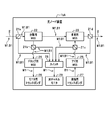
- Each optical node device 1aA to 1cA has the same configuration, and as shown in FIG. 2 as a representative of the optical node device 1bA, beam splitters (branch portions) 21a, 21b, 21c, which perform branching by transmission and reflection of optical signals, 21d, WSS (Wavelength Selective Switch) 22 for separation, WSS23 for multiplexing, WSS24 for dropping, WSS25 for ad, transponder 26 for monitoring, transponder 27 for transmission, switch 28, and optical. It is configured to include a channel monitor 29.
- WSS22 for separation, WSS23 for multiplexing, WSS24 for dropping, and WSS25 for ad are also referred to as WSS22 to 25.
- the beam splitters 21a, 21b, 21c, 21d are also referred to as a beam splitter 21.
- These components 21a to 21d and 22 to 29 are connected by an optical fiber as follows. That is, the beam splitter 21a is connected to the separation WSS 22 and the switch 28 by an optical fiber, and the separation WSS 22 is connected to the multiplexing WSS 23 and the beam splitter 21b.
- the multiplexing WSS 23 is connected to the beam splitters 21c and 21d.
- the beam splitter 21b is connected to the drop WSS 24 and the switch 28, and the beam splitter 21c is connected to the ad WSS 25 and the switch 28.
- the drop WSS 24 is connected to the monitor transponder 26, and the ad WSS 25 is connected to the transmission transponder 27.
- the switch 28 is connected to the optical channel monitor 29.
- the beam splitter 21a transmits the optical signal B1 on which the monitoring control signal M1 transmitted from the external optical fiber 2 is superimposed and outputs the optical signal B1 to the separation WSS 22. At the same time, it is reflected and output to the switch 28.
- the monitoring control signal M1 is a signal for performing optical path tracing, which is confirmation of continuity of the optical path set between the end points of the optical node devices 1aA to 1cA.
- the monitoring control signal M1 multiplexes unique optical path ID (Identification) information by intensity modulation that changes the intensity of the optical signal B1 over time.
- the monitoring control signal M1 can be superimposed on the optical signal B1 at each WSS 22 to 25, as shown by arrows M1a, M1b, M1c, M1d, M1e, and M1f in FIG. This superimposition can be performed by modulating the optical signal B1 with the monitoring control signal M1 including each unique optical path ID information from WSS 22 to 25 at a plurality of locations.
- the separation WSS 22 outputs the optical signal B1 on which the monitoring control signal M1 is superimposed to the multiplexing WSS 23, and also separates and outputs the optical signal B1 to the beam splitter 21b.
- the beam splitter 21b transmits the input monitoring control signal M1 and the optical signal B1 and outputs them to the drop WSS 24, and also reflects them and outputs them to the switch 28.
- the drop WSS 24 branches the monitoring control signal M1 from the monitoring control signal M1 and the optical signal B1 according to the wavelength, and outputs the monitoring control signal M1 to the monitor transponder 26.
- the monitor transponder 26 measures and monitors the optical power of the monitoring control signal M1. This monitor monitors whether the optical power is above a predetermined level indicating the normality of the optical path.
- the transmission transponder 27 outputs the optical signal B1 to the ad WSS 25.
- the add WSS 25 modulates the optical signal B1 with the monitoring control signal M1 and outputs the optical signal B1 to the multiplexing WSS 23 via the beam splitter 21c.
- the output monitoring control signal M1 and optical signal B1 are branched (reflected) by the beam splitter 21c and output to the switch 28.
- the multiplexing WSS 23 transmits the monitoring control signal M1 and the optical signal B1 from the separation WSS 22 to the external optical fiber 2 through the beam splitter 21d.
- the multiplexing WSS 23 multiplexes the monitoring control signal M1 and the optical signal B1 output from the ad WSS 25 and transmitted through the beam splitter 21c, and transmits the optical signal B1 through the beam splitter 21d to the external optical fiber 2.
- the monitoring control signal M1 and the optical signal B1 output from the add WSS 25 are reflected by the beam splitter 21c and output to the switch 28.
- the switch 28 selects the monitoring control signals M1 from the beam splitters 21a to 21d and outputs them to the optical channel monitor 29.
- the optical channel monitor 29 reads the time change of the optical power of the monitoring control signal M1 and demodulates the optical path ID information.
- the optical channel monitor 29 detects that the optical path is normally stretched as described later, based on the optical path ID information obtained by the demodulation.
- the optical channel monitor 29 holds unique information of the beam splitters 21a to 21d connected to the switch 28, and the switch 28 has a monitoring control signal M1 including optical path ID information branched by which beam splitter 21. It is possible to detect whether or not the input has been made. With this function, the optical channel monitor 29 splits WSS22 to 25 and monitoring control signals M1a to M1f on which monitoring control signals M1a to M1f (FIG. 1) including the optical path ID information are superimposed based on the optical path ID information. The beam splitters 21a to 21d branched immediately before the switch 28 are detected. This detection makes it possible to confirm (or detect) the normality of the optical path between the WSS 22 to 25 and the beam splitters 21a to 21d.
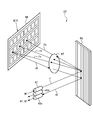
- the multiplexing WSS23 shown in FIG. 3 includes a fiber collimator (also referred to as a collimator) 61 for input, and collimators 62a and 62b for output, which are N times (for example, twice) the number of collimators 61 for input, and wavelength division. It includes a grating (diffraction grating) 65 that demultiplexes the multiplexed optical signals, a lens 67, and a spatial light modulator 68 composed of, for example, an LCOS (Liquid Crystal on Silicon).
- the input collimator 61 and the output collimators 62a and 62b are connected to an optical fiber.
- the input collimator 61 constitutes the input collimator according to claim.
- the output collimators 62a and 62b constitute the output collimator according to claim.
- the optical signal B1 from the optical fiber is incident on the grating 65 via the collimator 61 as shown by the arrow i1.
- the grating 65 diffracts and reflects the optical signal B1 at different angles depending on the wavelength, thereby performing demultiplexing (for example, 3 demultiplexing) as shown by arrows i1a, i1b, and i1c.
- demultiplexing for example, 3 demultiplexing
- the three-segmented optical signal is incident on the spatial light modulator 68 via the lens 67.
- the spatial light modulator 68 reflects the optical signal divided into three.
- the voltage B1V of the monitoring control signal M1 (referred to as the monitoring control voltage B1V) is applied to the spatial light modulator 68 to perform intensity modulation.
- the optical signal B1 on which the monitoring control signal M1 is superimposed by this intensity modulation is output from the desired output collimator 62a via the lens 67 and the grating 65 as represented by the one optical signal by the arrow o2. ..
- the optical signal is reflected by the spatial light modulator 68. As shown in FIG. 4, this reflection angle can be changed from the angle ⁇ 2 to an angle ⁇ 1 smaller than the angle ⁇ 2, so that the efficiency at which the optical signal is coupled to the collimator 62a on the output side can be made small and variable.
- the amount of attenuation of the optical signal B1 can be made small and variable according to this variation.
- phase slope 71 that changes the reflection angle changes.
- the phase slope 71 is indicated by the pixel position of the axis (first axis) along the pixel arrangement direction of the spatial light modulator 68 and the value of "phase / 2 ⁇ " of the second axis orthogonal to the first axis. It changes according to the phase line c2 or c1.
- the phase line c2 gradually rises from 0, the value of "phase / 2 ⁇ " becomes the maximum value of ⁇ 2 at the pixel position t1, and after abruptly decreasing from ⁇ 2 to 0, it gradually decreases again. It becomes higher and becomes the maximum value of ⁇ 2 at the position t2. This operation is repeated.
- the input light signal B1 indicated by the arrow i1 is reflected by the reflection angle ⁇ 2 corresponding to the phase line c2, and is output to the collimator 62a on the output side as indicated by the arrow o2.
- the amount of attenuation of the optical signal B1 in the collimator 62a is shown by a mountain-shaped curve 72a.
- phase line c1 shown by the broken line gradually rises from 0, and the value of "phase / 2 ⁇ " is smaller than the above ⁇ 2 at the pixel position t1. It is the maximum value of ⁇ 1. Further, the phase line c1 sharply decreases from ⁇ 1 to 0, then gradually rises again to reach the maximum value of ⁇ 1 at the position t2. This operation is repeated.
- the reflection angle ⁇ 1 is smaller than the reflection angle ⁇ 2.
- the optical signal B1 indicated by the arrow o1 to which the input optical signal B1 of the arrow i1 is reflected at this angle ⁇ 1 is output to the collimator 62a on the output side.
- the attenuation amount (for example, 80%) related to the optical signal B1 indicated by the arrow o1 becomes a curve 72b, and is deviated so as to be smaller than the attenuation amount (for example, 90%) indicated by the curve 72a related to the optical signal B1 indicated by the arrow o2. ..
- the optical path P3 is the transmission transponder 27 of the optical node device 1aA via the ad WSS25, the beam splitter 21c, the multiplexing WSS23 and the beam splitter 21d, and the optical node device 1bA via the optical fiber 2. It reaches the beam splitter 21a. Further, it reaches the beam splitter 21a of the optical node device 1cA via the optical fiber 2 via the WSS22 for separation, the WSS23 for multiplexing, and the beam splitter 21d of the optical node device 1bA. Further, it reaches the monitor transponder 26 via the separation WSS22, the beam splitter 21b, and the drop WSS24 of the optical node device 1cA.
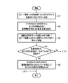
- step S1 shown in FIG. 5 the optical signal B1 transmitted from the transmission transponder 27 is output to the ad WSS 25 via the optical path P3.
- step S2 it is assumed that the monitoring control signal M1a including the optical path ID information a is superimposed on the optical signal B1 by the WSS25 for ad. At the time of this superposition, the unique information of the ad WSS25 of the optical node device 1aA is also added.
- step S3 the optical signal B1 (referred to as superimposed optical signal) on which the monitoring control signal M1a is superimposed relays the optical node apparatus 1bA via the optical path P3 and heads toward the monitor transponder 26 of the optical node apparatus 1cA. Will be sent.
- step S4 it is determined whether or not the superimposed optical signal is transmitted by all the beam splitters 21 through which the optical path p3 passes. It is assumed that the monitor transponder 26 at the end point detects the monitoring control signal M1a from the superimposed optical signal to make this determination.
- the monitor transponder 26 measures and monitors the optical power of the monitoring control signal M1a in step S5. This monitor monitors whether the optical power is above a predetermined level indicating the normality of the optical path.
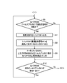
- step S4 when it is determined in step S4 that all the beam splitters 21 are not transmitted (No), the superimposed optical signal is reflected by the beam splitter 21d on the most starting point side of the optical path P3 in step S6 of FIG. It is determined whether or not the branch has been split.
- step S8 in the switch 28, as shown by the broken line arrow Y1b, the monitoring control signal M1a is selected and output to the optical channel monitor 29.
- step S9 the optical channel monitor 29 reads the time change of the optical power of the monitoring control signal M1a and demodulates the optical path ID information a. Further, the optical channel monitor 29 detects the optical path P3 between the ad WSS 25 and the beam splitter 21d based on the optical path ID information a, and detects (monitors) the normality of the detected optical path P3. ..
- step S10 it is determined whether or not the next beam splitter 21 on the subsequent stage side in the optical path P3 exists. This determination is made by detecting the monitoring control signal M1a branched by the next beam splitter 21 by the optical channel monitor 29. If it can be detected, it is judged to exist, and if it cannot be detected, it is judged to not exist. As a result of this determination, since the beam splitter 21a of the next optical node device 1bA exists, the process returns to step S6. On the other hand, if it does not exist, the optical path trace processing is terminated.
- step S6 the optical channel monitor 29 determines whether or not the superimposed optical signal is branched by the beam splitter 21a of the next optical node device 1bA.
- the branched superimposed optical signal is output to the switch 28 in step S7 as shown by the broken line arrow Y2a.
- step S8 in the switch 28, as shown by the broken line arrow Y2b, the monitoring control signal M1a is selected and output to the optical channel monitor 29.
- step S9 the optical channel monitor 29 reads the time change of the optical power of the monitoring control signal M1a and demodulates the optical path ID information a and the optical path ID information a of the ad WSS25 and the beam splitter 21a. Further, the optical channel monitor 29 detects the optical path P3 between the ad WSS 25 and the beam splitter 21a based on the optical path ID information a, and detects (monitors) the normality of the detected optical path P3. ..
- step S10 the optical channel monitor 29 determines whether or not the next beam splitter 21 on the subsequent stage side in the optical path P3 exists. As a result of this determination, since the beam splitter 21d of the next optical node device 1bA exists, the process returns to step S6.
- step S6 it is determined whether or not the superimposed optical signal is branched by the beam splitter 21d of the next optical node device 1bA.
- the branched superimposed optical signal is output to the switch 28 in step S7 as shown by the broken line arrow Y2c.
- step S8 in the switch 28, as shown by the broken line arrow Y2b, the monitoring control signal M1a is selected and output to the optical channel monitor 29.
- step S9 the optical channel monitor 29 reads the time change of the optical power of the monitoring control signal M1a and demodulates the optical path ID information a and the optical path ID information a of the ad WSS25 and the beam splitter 21d. Further, the optical channel monitor 29 detects the optical path P3 between the ad WSS 25 and the beam splitter 21d based on the optical path ID information a, and detects (monitors) the normality of the detected optical path P3. ..
- step S10 it is determined whether or not the next beam splitter 21 on the subsequent stage side in the optical path P3 exists. As a result of this determination, since the beam splitter 21a of the next optical node device 1cA exists, the process returns to step S6.
- step S6 it is determined whether or not the superimposed optical signal is branched by the beam splitter 21a of the next optical node device 1cA.
- the branched superimposed optical signal is output to the switch 28 in step S7 as shown by the broken line arrow Y3a.
- step S7 in the switch 28, as shown by the broken line arrow Y3b, the monitoring control signal M1a is selected and output to the optical channel monitor 29.
- step S8 the optical channel monitor 29 reads the time change of the optical power of the monitoring control signal M1a and demodulates the optical path ID information a and the optical path ID information of the ad WSS 25 and the beam splitter 21a. Further, the optical channel monitor 29 detects the optical path P3 between the ad WSS 25 and the beam splitter 21a based on the optical path ID information a, and detects (monitors) the normality of the detected optical path P3. ..
- step S10 it is determined whether or not the next beam splitter 21 on the subsequent stage side in the optical path P3 exists. As a result of this determination, since the beam splitter 21b of the next optical node device 1cA exists, the process returns to step S6.
- step S6 it is determined whether or not the superimposed optical signal is branched by the beam splitter 21b of the next optical node device 1cA.
- the branched superimposed optical signal is output to the switch 28 in step S7 as shown by the broken line arrow Y3c.
- step S8 in the switch 28, as shown by the broken line arrow Y3b, the monitoring control signal M1a is selected and output to the optical channel monitor 29.
- step S9 the optical channel monitor 29 reads the time change of the optical power of the monitoring control signal M1a and demodulates the optical path ID information a and the optical path ID information a of the ad WSS25 and the beam splitter 21b. Further, the optical channel monitor 29 detects the optical path P3 between the ad WSS 25 and the beam splitter 21b based on the optical path ID information a, and detects (monitors) the normality of the detected optical path P3. ..
- step S10 it is determined whether or not the next beam splitter 21 on the subsequent stage side in the optical path P3 exists. As a result of this determination, since the next beam splitter 21 does not exist, the optical path tracing process is terminated.
- the optical node devices 1aA to 1cA include a transmission transponder 27, a WSS 22 to 25, a beam splitter 21, and a monitor transponder 26.
- the transmission transponder 27 transmits the optical signal B1 via the optical path P3 stretched over the optical fiber 2.
- the WSS 22 to 25 multiplex the transmitted optical signal B1 with a monitoring control signal M1 that performs an optical path trace that confirms the continuity of the optical path P3.
- the beam splitter 21 branches the optical signal B1 to which the monitoring control signal M1 is multiplexed.
- the monitor transponder 26 measures and monitors the optical power of the monitoring control signal M1 multiplexed with the optical signal B1 branched by the beam splitter 21. Further, the monitor transponder 26 is configured to monitor whether or not the monitored optical power is at or above a predetermined level indicating the normality of the optical path P3.
- the normality of the optical path P3 can be determined from the optical power of the monitoring control signal M1 multiplexed with the optical signal B1 transmitted from the other optical node device 1aA. Since the normality of the optical path P3 is determined by the dedicated monitoring control signal M1, the abnormality of the optical path P3 set between the optical node devices 1aA and 1cA can be appropriately determined. Further, even in the optical node device 1bA that relays the optical path P3 between the optical node devices 1aA and 1cA, the normality of the optical path P3 can be determined by the optical node device 1bA for relaying, so that the optical path trace can be properly performed. It can be carried out.
- the optical channel monitor 29 for monitoring the optical path ID information obtained by reading and demodulating the time change of the optical power of the control signal M1 is provided.
- the optical channel monitor 29 is configured to detect the normality of the optical path P3 between the transmission transponder 27 and the beam splitter 21 that branches the optical signal B1 based on the optical path ID information.
- the normality of the path P3 can be confirmed.
- the optical signal B1 is incident via the input collimator 61 to which the optical signal B1 is input and the input collimator 61, and the WSS 22 to 25 are diffracted at different angles according to the wavelength of the optical signal B1.
- Spatial light that reflects the diffractive grid 65 that demultiplexes by reflecting and demultiplexes the demultiplexed optical signal B1 and applies the voltage B1V of the monitoring control signal M1 to the optical signal B1 at the time of reflection to apply intensity modulation.
- the configuration includes a modulator 68 and an output collimator 62a that outputs an optical signal B1 reflected by the spatial optical modulator 68.
- WSS 22 to 25 can be composed of an optical system component that is combined by using a collimator, a diffractive grid, and a spatial light modulator on the input side and the output side. Therefore, it is possible to reduce the size of the optical node devices 1aA to 1cA provided with WSS 22 to 25.
- the OTN system 10A has a configuration in which the optical node devices 1aA to 1cA according to any one of (1a) to (3a) above are subordinately connected by an optical fiber 2 via a beam splitter 21.
- the optical path P3 is normal from the optical power of the monitoring control signal M1 multiplexed with the optical signal B1 transmitting the optical path P3. You can judge the sex. Since this determination is based on the dedicated monitoring control signal M1, the abnormality of the optical path P3 can be appropriately determined. Further, even in the optical node devices 1aA to 1cA that relay the optical path P3 between the optical node devices 1aA to 1cA, the normality of the optical path P3 can be determined appropriately by the optical node devices 1aA to 1cA for relaying. Optical path tracing can be performed.
- the OTN system 10A transmits a monitoring control signal M1 having unique optical path ID information in each of WSS 22 to 25 on the optical path P3 stretched between the optical node devices 1aA to 1cA connected subordinately. , It is configured to be multiplexed with the optical signal B1 that transmits the optical path P3.
- the monitoring control signal M1 having unique optical path ID information can be multiplexed with the optical signal B1 in any WSS 22 to 25. Therefore, the optical path P3 between the WSS 22 to 25 of the desired optical node devices 1aA to 1cA and the beam splitter 21 of the other optical node devices 1aA to 1cA, the transmission transponder 27 at the starting point, and the desired optical node devices 1aA to 1cA. It is possible to confirm the normality of the optical path P3 in an arbitrary section, such as the optical path P3 between WSS 22 and 25 and the optical path P3 between WSS 22 and 25 of the desired optical node devices 1aA to 1cA and the monitoring transponder 26 at the end point.
- This program causes the computer to transmit an optical signal B1 via an optical path P3 stretched on an optical fiber, and performs an optical path P3 trace for confirming the continuity of the optical path P3 to the transmitted optical signal B1.
- Means for multiplexing the monitoring control signal M1 means for branching the optical signal B1 to which the monitoring control signal M1 is multiplexed, means for measuring and monitoring the optical power of the monitoring control signal M1 multiplexed with the optical signal B1, and monitoring. It functions as a means for monitoring whether or not the optical power is above a predetermined level indicating the normality of the optical path P3.
- a transmission transponder that transmits an optical signal via an optical path stretched over an optical fiber, and a monitoring control signal that performs optical path tracing for confirming the continuity of the optical path are multiplexed with the transmitted optical signal. Measure the optical power of the WSS (Wavelength Selective Switch), the branch portion that branches the optical signal to which the monitoring control signal is multiplexed, and the monitoring control signal that is multiplexed by the optical signal branched at the branch portion.
- WSS Widelength Selective Switch
- a monitor transponder to be monitored is provided, and the monitor transponder is an optical node device for monitoring whether or not the monitored optical power is at or above a predetermined level indicating the normality of the optical path. ..
- the normality of the optical path can be determined from the optical power of the monitoring control signal multiplexed with the optical signal transmitted from another optical node device. Since the normality of the optical path is determined by the dedicated monitoring control signal, the abnormality of the optical path set between the optical node devices can be appropriately determined. Further, even in the optical node device that relays the optical path between the optical node devices, the normality of the optical path can be determined by the optical node device for relay, so that the optical path trace can be appropriately performed.
- the WSS is multiplexed including the unique optical path ID (Identification) information
- the monitoring is multiplexed with the optical signal branched at the branch portion.
- the optical channel monitor is provided with an optical channel monitor that monitors the optical path ID information obtained by reading and demodulating the time change of the optical power of the control signal, and the optical channel monitor branches the transmission transponder and the optical signal based on the optical path ID information.
- the optical node device according to (1) above characterized in that the normality of the optical path between the branch portions is monitored.
- the normality of the optical path between the transmission transponder at the start point of transmitting the optical signal, the branch portion arranged in the middle between the monitor transponder at the end point of receiving the optical signal, and the start point. Can be confirmed.
- an optical signal is incident via an input collimator to which an optical signal is input and the input collimator, and the WSS is demultiplexed by being diffracted and reflected at different angles according to the wavelength of the optical signal.
- the optical node device according to any one of (1) to (3) above, which comprises an output collimeter that outputs a reflected optical signal.
- the WSS can be composed of an optical system component that is combined using a collimator, a diffractive grid, and a spatial light modulator on the input side and the output side. Since a similar WSS of a plurality of output types with this one input exists as a general-purpose type, the WSS of the present embodiment can be easily created by using this WSS.
- the normality of the optical path can be judged from the optical power of the monitoring control signal multiplexed with the optical signal transmitted through the optical path. Since this judgment is based on a dedicated monitoring control signal, it is possible to properly judge an abnormality in the optical path. Further, even in the optical node device that relays the optical path between the optical node devices, the normality of the optical path can be determined by the optical node device for relay, so that the optical path trace can be appropriately performed.
- a monitoring control signal having unique optical path ID information is multiplexed with the optical signal transmitting the optical path.
- a monitoring control signal having unique optical path ID information can be multiplexed with an optical signal in any WSS. Therefore, an optical path between the WSS of the desired optical node device and the branch of another optical node device, an optical path between the transmission transponder at the starting point and the WSS of the desired optical node device, and the WSS of the desired optical node device. You can check the normality of the optical path in any section, such as the optical path between the and the end point of the monitor transponder.
- Optical node device 10A OTN system 21a-21d Beam splitter (branch) 22 WSS for separation 23 WSS for multiplex WSS for 24 drops 25 WSS for ads 26 Transponder for monitor 27 Transponder for transmission 28 Switch 29 Optical channel monitor P3 Optical path 61 Fiber collimator for input 62a, 62b Fiber collimator for output 65 Grating (diffraction grating) 67 Lens 68 Spatial Light Modulator B1V Monitoring Control Voltage
Landscapes
- Engineering & Computer Science (AREA)
- Computer Networks & Wireless Communication (AREA)
- Computing Systems (AREA)
- Physics & Mathematics (AREA)
- Electromagnetism (AREA)
- Signal Processing (AREA)
- Optical Communication System (AREA)
Abstract
光ノード装置(1aA~1cA)は、送信用トランスポンダ(27)と、WSS(22~25)と、ビームスプリッタ(21)と、モニタ用トランスポンダ(26)とを備える。送信用トランスポンダ(27)は、光信号(B1)を光ファイバ(2)に設定された光パス(P3)を介して送信する。WSS(22~25)は、送信された光信号(B1)に、光パス(P3)の導通確認である光パストレースを行う監視制御信号(M1)を多重する。モニタ用トランスポンダ(26)は、ビームスプリッタ(21)で分岐された光信号(B1)に多重されている監視制御信号(M1)の光パワーを測定してモニタし、更に、モニタされた光パワーが光パス(P3)の正常性を示す所定のレベル以上か否かを監視する。
Description
本発明は、複数の光ノード装置を光ファイバで接続して構成される光トランスポートネットワークシステムにおいて、光ノード装置を中継する光パスの導通確認である光パストレースを行う光ノード装置、光トランスポートネットワークシステム、光パストレース方法及びプログラムに関する。
現在、光トランスポートネットワーク(OTN:Optical Transport Network)システムのOH(保守オーバーヘッド)を利用した光パストレースが、非特許文献1に示すITU-T勧告G.709(OTNインタフェース)で規定されている。また、光ノード装置による中継ノードでは、光パワーが所定のレベルであるか否かに応じて、光信号が到達しているか否かを判定することが規定されている。
図7は従来のOTNシステムの構成を示すブロック図である。図7に示すOTNシステム10は、複数の光ノード装置1a,1b,1c,を備え、各光ノード装置1a~1cが光ファイバ2で接続されて構成されている。各光ノード装置1a~1cは、各々異なる固有のNW(ネットワーク)ドメインを有する。また、各光ノード装置1a~1cは、複数のOXC(Optical Cross Connect)3a~3hと、複数のトランスポンダ4とを備えて構成されている。各OXC3a~3hには、複数のトランスポンダ4が接続されており、各OXC3a~3h間は、光ファイバ2で接続されている。
OXC3a~3hは、光ファイバ2を介してデータ伝送のための光伝送路を任意に設定するスイッチング制御を行うものである。トランスポンダ4は、図示せぬ通信装置とのデータの中継を行うものである。
光ノード装置1aのトランスポンダ4a及びOXC3a,3bと、光ノード装置1bのOXC3c,3dと、光ノード装置1cのOXC3e及びトランスポンダ4bとは、光ファイバ2で接続され、光ファイバ2を介して光パスP1が設定されている。つまり、光ノード装置1aのトランスポンダ4aと光ノード装置1cのトランスポンダ4bとが、光ノード装置1bを中継して光パスP1により接続され、光パスP1を光信号が伝送するようになっている。
また、光ノード装置1cのトランスポンダ4c及びOXC3fと、光ノード装置1bのOXC3g、OXC3h及びトランスポンダ4dとは、光ファイバ2で接続され、この光ファイバ2を介して光パスP2が設定されている。つまり、トランスポンダ4cとトランスポンダ4dとが光パスP2により接続され、光パスP2を光信号が伝送するようになっている。
このような、OTNシステム10においては、光ノード装置1a~1cのNWドメイン毎に、NW管理者が異なっている。各々のNW管理者が、トランスペアレント(透過)モードをベースとして、光ノード装置1a~1cにおいて光パスP1,P2が正常に張られているか否かをモニタしている。
ITU-T G.709/Y.1331, "Interfaces for the optical transport network" (2020.06.16)
上述したOTNシステム10においては、トランスペアレントモードなので、光ノード装置1a~1cにおけるモニタ機能が光パワーレベルに限定される。このため、光パス(例えば光パスP1)の設定に失敗した場合の故障分析において次のような課題があった。即ち、光パスP1が正常に設定されていないにも関わらず、スイッチの異常等により本来と異なる光信号が届いている場合、光パワーレベルでモニタするので、本来の光信号と区別できない。つまり、誤った光信号が所定のレベル以上の場合、正常と判断されるので異常とは判断できない課題があった。
また、光パスが、異なるNWオペレータの管理する複数のNWドメインの光ノード装置1a~1cに跨って設定されるとする。上述したように、光ノード装置1aと光ノード装置1c間に、光ノード装置1bを跨って光パスP1が設定されている場合、中継の光ノード装置1bは光パスP1の端点を含まないので、そのNWドメインのNWオペレータは光パストレースができないという課題があった。
本発明は、このような事情に鑑みてなされたものであり、光ノード装置間に設定される光パスの異常を適正に判断でき、光ノード装置間で光パスの中継を行う光ノード装置でも適正に光パストレースを行うことを課題とする。
上記課題を解決するため、本発明の光ノード装置は、光信号を光ファイバに張られた光パスを介して送信する送信用トランスポンダと、前記送信された光信号に、前記光パスの導通確認である光パストレースを行う監視制御信号を多重するWSS(Wavelength Selective Switch)と、前記監視制御信号が多重された光信号を分岐する分岐部と、前記分岐部で分岐された光信号に多重されている監視制御信号の光パワーを測定してモニタするモニタ用トランスポンダとを備え、前記モニタ用トランスポンダは、前記モニタされた光パワーが前記光パスの正常性を示すレベル以上か否かを監視することを特徴とする。
本発明によれば、光ノード装置間に設定される光パスの異常を適正に判断でき、光ノード装置間で光パスの中継を行う光ノード装置でも適正に光パストレースを行うことができる。
以下、本発明の実施形態を、図面を参照して説明する。但し、本明細書の全図において機能が対応する構成部分には同一符号を付し、その説明を適宜省略する。
<実施形態の構成>
図1は、本発明の実施形態に係る光ノード装置を用いたOTNシステムの構成を示すブロック図である。
<実施形態の構成>
図1は、本発明の実施形態に係る光ノード装置を用いたOTNシステムの構成を示すブロック図である。
図1に示すOTNシステム10Aは、光ファイバ2で従属接続された複数の光ノード装置1aA,1bA,1cAを備える。各光ノード装置1aA~1cAは同一構成であり、図2に光ノード装置1bAを代表して示すように、光信号の透過及び反射による分岐を行うビームスプリッタ(分岐部)21a,21b,21c,21dと、分離用WSS(Wavelength Selective Switch:波長選択スイッチ)22と、多重用WSS23と、ドロップ用WSS24と、アド用WSS25と、モニタ用トランスポンダ26と、送信用トランスポンダ27と、スイッチ28と、光チャネルモニタ29とを備えて構成されている。なお、分離用WSS22、多重用WSS23、ドロップ用WSS24、及びアド用WSS25を、WSS22~25とも称す。ビームスプリッタ21a,21b,21c,21dを、ビームスプリッタ21とも称す。
これらの構成要素21a~21d,22~29は光ファイバで次のように接続されている。即ち、ビームスプリッタ21aは、光ファイバで分離用WSS22及びスイッチ28に接続され、分離用WSS22は、多重用WSS23及びビームスプリッタ21bに接続されている。多重用WSS23は、ビームスプリッタ21c,21dに接続されている。ビームスプリッタ21bは、ドロップ用WSS24及びスイッチ28に接続され、ビームスプリッタ21cは、アド用WSS25及びスイッチ28に接続されている。
ドロップ用WSS24は、モニタ用トランスポンダ26に接続され、アド用WSS25は、送信用トランスポンダ27に接続されている。スイッチ28は、光チャネルモニタ29に接続されている。
このような接続構成において、図2に示すように、ビームスプリッタ21aは、外部の光ファイバ2から伝送されてきた監視制御信号M1が重畳された光信号B1を、透過して分離用WSS22へ出力すると共に、反射してスイッチ28へ出力する。監視制御信号M1は、光ノード装置1aA~1cAの端点間に張られて設定される光パスの導通確認である光パストレースを行うための信号である。この監視制御信号M1は、光信号B1の強度を時間的に変化させる強度変調により、固有の光パスID(Identification)情報を多重するものである。
監視制御信号M1は、図1に矢印M1a,M1b,M1c,M1d,M1e,M1fで示すように、各WSS22~25において光信号B1に重畳可能となっている。この重畳は、複数個所のWSS22~25から、各々固有の光パスID情報を含む監視制御信号M1で光信号B1を変調して行うことが可能となっている。
図2に戻って、分離用WSS22は、監視制御信号M1が重畳された光信号B1を多重用WSS23へ出力すると共に、分離してビームスプリッタ21bへ出力する。ビームスプリッタ21bは、入力された監視制御信号M1及び光信号B1を、透過してドロップ用WSS24へ出力すると共に、反射してスイッチ28へ出力する。
ドロップ用WSS24は、監視制御信号M1及び光信号B1から監視制御信号M1を波長に応じて分岐し、モニタ用トランスポンダ26へ出力する。モニタ用トランスポンダ26は、監視制御信号M1の光パワーを測定してモニタする。このモニタでは、光パワーが光パスの正常性を示す所定のレベル以上か否かを監視する。
送信用トランスポンダ27は、光信号B1をアド用WSS25に出力する。アド用WSS25は、光信号B1を監視制御信号M1で変調し、ビームスプリッタ21cを介して多重用WSS23へ出力する。この出力される監視制御信号M1及び光信号B1は、ビームスプリッタ21cで分岐(反射)されてスイッチ28へ出力される。
多重用WSS23は、分離用WSS22からの監視制御信号M1及び光信号B1を、ビームスプリッタ21dを透過して外部の光ファイバ2へ伝送する。又は、多重用WSS23は、アド用WSS25から出力され、ビームスプリッタ21cを透過してきた監視制御信号M1及び光信号B1を多重し、ビームスプリッタ21dを透過して外部の光ファイバ2へ伝送する。また、アド用WSS25から出力された監視制御信号M1及び光信号B1は、ビームスプリッタ21cで反射されてスイッチ28へ出力される。
スイッチ28は、各ビームスプリッタ21a~21dからの監視制御信号M1を選択して光チャネルモニタ29へ出力する。光チャネルモニタ29は、監視制御信号M1の光パワーの時間変化を読み取って光パスID情報を復調する。光チャネルモニタ29は、その復調により得られた光パスID情報を基に、後述のように光パスが正常に張られていることを検出する。
例えば、光チャネルモニタ29は、スイッチ28に接続されたビームスプリッタ21a~21dの固有情報を保持しており、スイッチ28が、どのビームスプリッタ21で分岐された光パスID情報を含む監視制御信号M1を入力したかが検出可能となっている。この機能によって、光チャネルモニタ29は、光パスID情報を基に、この光パスID情報を含む監視制御信号M1a~M1f(図1)を重畳したWSS22~25と、監視制御信号M1a~M1fをスイッチ28の直前で分岐したビームスプリッタ21a~21dとを検出する。この検出によってWSS22~25とビームスプリッタ21a~21d間の光パスの正常性が確認(又は検出)可能となっている。
<WSSの構成例>
ここで、同一構成の各WSS22~25の具体的な構成例を、図3に多重用WSS23を代表して示し、その説明を行う。
ここで、同一構成の各WSS22~25の具体的な構成例を、図3に多重用WSS23を代表して示し、その説明を行う。
図3に示す多重用WSS23は、入力用のファイバコリメータ(コリメータともいう)61と、入力用のコリメータ61のN倍(例えば2倍)の個数である出力用のコリメータ62a,62bと、波長分割多重された光信号の分波を行うグレーティング(回折格子)65と、レンズ67と、例えばLCOS(Liquid Crystal on Silicon)で構成される空間光変調器68とを備えて構成されている。入力用のコリメータ61と、出力用のコリメータ62a,62bは、光ファイバに接続されている。なお、入力用のコリメータ61は、請求項記載の入力用コリメータを構成する。出力用のコリメータ62a,62bは、請求項記載の出力用コリメータを構成する。
このような構成において、光ファイバからの光信号B1がコリメータ61を介して、矢印i1で示すように、グレーティング65に入射される。グレーティング65は、光信号B1に対して、波長に応じて異なる角度に回折して反射することで、矢印i1a,i1b,i1cで示すように、分波(例えば3分波)を行う。3分波された光信号は、レンズ67を介して空間光変調器68に入射される。
空間光変調器68は、3分波された光信号を反射する。この際、監視制御信号M1の電圧B1V(監視制御電圧B1Vという)を空間光変調器68に印加して強度変調を掛ける。この強度変調により監視制御信号M1が重畳された光信号B1が、矢印o2で1光信号を代表して示すように、レンズ67及びグレーティング65を介して所望の出力用のコリメータ62aから出力される。
上記矢印i1c,o2で示すように、光信号を空間光変調器68で反射させている。この反射角度は、図4に示すように、角度θ2から、当該角度θ2よりも小さい角度θ1に変えることで、光信号が出力側のコリメータ62aに結合する際の効率を小さく可変できる。この可変に応じて光信号B1の減衰量を小さく可変できる。
つまり、レベルが時間的に変化する監視制御電圧B1Vを空間光変調器68に印加すると、反射角度を変える位相スロープ71が変化する。この位相スロープ71は、空間光変調器68のピクセルの配列方向に沿った軸(第1軸)のピクセル位置と、第1軸に直交する第2軸の「位相/2π」の値とで示す位相線c2又はc1に応じて変化する。監視制御電圧B1Vに応じて、位相線c2が0から徐々に高くなってピクセル位置t1で「位相/2π」の値がφ2の最大値となり、このφ2から0まで急激に減少した後、再び徐々に高くなって位置t2でφ2の最大値となる。この動作を繰り返す。
上記位相線c2に応じた反射角度θ2により、矢印i1で示す入力光信号B1が反射され、矢印o2で示すように、出力側のコリメータ62aへ出力される。このコリメータ62aにおける光信号B1の減衰量を山形状の曲線72aで示す。
一方、印加される監視制御電圧B1Vのレベルが上記よりも低くなると、破線で示す位相線c1が0から徐々に高くなってピクセル位置t1で、「位相/2π」の値が上記φ2よりも小さいφ1の最大値となる。更に、位相線c1は、そのφ1から0まで急激に減少した後、再び徐々に高くなって位置t2でφ1の最大値となる。この動作を繰り返す。
この位相線c1では、反射角度θ1が上記反射角度θ2より小さくなる。この角度θ1で矢印i1の入力光信号B1が反射された矢印o1で示す光信号B1は、出力側のコリメータ62aへ出力される。この際の矢印o1で示す光信号B1に係る減衰量(例えば80%)は曲線72bとなり、矢印o2の光信号B1に係る曲線72aで示す減衰量(例えば90%)よりも小さくなるようにずれる。
<実施形態の動作>
次に、本実施形態に係るOTNシステム10Aにおける光パストレースの動作を、図5及び図6のフローチャートを参照して説明する。但し、図1に示すように、光ノード装置1aAの送信用トランスポンダ27(始点)と、光ノード装置1cAのモニタ用トランスポンダ26(終点)との間に、光ノード装置1bAを中継して光パスP3が張られているとする。
次に、本実施形態に係るOTNシステム10Aにおける光パストレースの動作を、図5及び図6のフローチャートを参照して説明する。但し、図1に示すように、光ノード装置1aAの送信用トランスポンダ27(始点)と、光ノード装置1cAのモニタ用トランスポンダ26(終点)との間に、光ノード装置1bAを中継して光パスP3が張られているとする。
詳細には、光パスP3は、光ノード装置1aAの送信用トランスポンダ27から、アド用WSS25、ビームスプリッタ21c、多重用WSS23及びビームスプリッタ21dを経由し、光ファイバ2を介して光ノード装置1bAのビームスプリッタ21aに至る。更に、光ノード装置1bAの分離用WSS22、多重用WSS23及びビームスプリッタ21dを経由し、光ファイバ2を介して光ノード装置1cAのビームスプリッタ21aに至る。更に、光ノード装置1cAの分離用WSS22、ビームスプリッタ21b、ドロップ用WSS24を経由してモニタ用トランスポンダ26に到達している。
図5に示すステップS1において、送信用トランスポンダ27から送信された光信号B1は、光パスP3を介してアド用WSS25へ出力される。
ステップS2において、アド用WSS25で光信号B1に光パスID情報aを含む監視制御信号M1aが重畳されたとする。この重畳の際に、光ノード装置1aAのアド用WSS25の固有情報も付加される。
ステップS3において、監視制御信号M1aが重畳された光信号B1(重畳光信号という)は、光パスP3を経由し、光ノード装置1bAを中継して光ノード装置1cAのモニタ用トランスポンダ26へ向かって送信される。
ステップS4において、重畳光信号は、光パスp3が通る全てのビームスプリッタ21で透過されたか否かが判断される。この判断は、終点のモニタ用トランスポンダ26が、重畳光信号から監視制御信号M1aを検出して行うとする。
この判断の結果、光パスP3が通る全てのビームスプリッタ21で透過していれば(Yes)、ステップS5において、モニタ用トランスポンダ26は、監視制御信号M1aの光パワーを測定してモニタする。このモニタでは、光パワーが光パスの正常性を示す所定のレベル以上か否かを監視する。この表示をNW管理者が確認することで、始点の送信用トランスポンダ27と、光ノード装置1bAを中継した終点のモニタ用トランスポンダ26間の全長の光パスP3の正常性を把握できる。
一方、上記ステップS4で全てのビームスプリッタ21を透過していない(No)と判断された場合、図6のステップS6において、光パスP3の最も始点側のビームスプリッタ21dで重畳光信号が反射によって分岐されたか否かが判断される。
この判断の結果、分岐された(Yes)とすると、分岐された重畳光信号が、ステップS7において、図1の破線矢印Y1aで示すように、スイッチ28へ出力される。
ステップS8において、スイッチ28では、破線矢印Y1bで示すように、監視制御信号M1aが選択されて光チャネルモニタ29へ出力される。
ステップS9において、光チャネルモニタ29は、監視制御信号M1aの光パワーの時間変化を読み取って光パスID情報aを復調する。更に、光チャネルモニタ29は、その光パスID情報aを基に、アド用WSS25とビームスプリッタ21d間の光パスP3を検出し、この検出された光パスP3の正常性を検出(モニタ)する。
ステップS10において、光パスP3における次の後段側のビームスプリッタ21が存在するか否かを判断する。この判断は、次のビームスプリッタ21で分岐された監視制御信号M1aを光チャネルモニタ29が検出して行うとする。検出できれば存在し、検出できなければ存在しないと判断される。この判断の結果、次の光ノード装置1bAのビームスプリッタ21aが存在するので、ステップS6に戻る。一方、存在しない場合は、光パストレース処理を終了する。
即ち、ステップS6において、光チャネルモニタ29で、次の光ノード装置1bAのビームスプリッタ21aで重畳光信号が分岐されたか否かが判断される。
この判断の結果、分岐された(Yes)とすると、分岐された重畳光信号が、ステップS7において、破線矢印Y2aで示すように、スイッチ28へ出力される。
ステップS8において、スイッチ28では、破線矢印Y2bで示すように、監視制御信号M1aが選択されて光チャネルモニタ29へ出力される。
ステップS9において、光チャネルモニタ29は、監視制御信号M1aの光パワーの時間変化を読み取って光パスID情報aと、アド用WSS25及びビームスプリッタ21aの光パスID情報aを復調する。更に、光チャネルモニタ29は、その光パスID情報aを基に、アド用WSS25とビームスプリッタ21a間の光パスP3を検出し、この検出された光パスP3の正常性を検出(モニタ)する。
ステップS10において、光チャネルモニタ29は、光パスP3における次の後段側のビームスプリッタ21が存在するか否かを判断する。この判断の結果、次の光ノード装置1bAのビームスプリッタ21dが存在するので、ステップS6に戻る。
即ち、ステップS6において、次の光ノード装置1bAのビームスプリッタ21dで重畳光信号が分岐されたか否かが判断される。
この判断の結果、分岐された(Yes)とすると、分岐された重畳光信号が、ステップS7において、破線矢印Y2cで示すように、スイッチ28へ出力される。
ステップS8において、スイッチ28では、破線矢印Y2bで示すように、監視制御信号M1aが選択されて光チャネルモニタ29へ出力される。
ステップS9において、光チャネルモニタ29は、監視制御信号M1aの光パワーの時間変化を読み取って光パスID情報aと、アド用WSS25及びビームスプリッタ21dの光パスID情報aを復調する。更に、光チャネルモニタ29は、その光パスID情報aを基に、アド用WSS25とビームスプリッタ21d間の光パスP3を検出し、この検出された光パスP3の正常性を検出(モニタ)する。
ステップS10において、光パスP3における次の後段側のビームスプリッタ21が存在するか否かを判断する。この判断の結果、次の光ノード装置1cAのビームスプリッタ21aが存在するので、ステップS6に戻る。
即ち、ステップS6において、次の光ノード装置1cAのビームスプリッタ21aで重畳光信号が分岐されたか否かが判断される。
この判断の結果、分岐された(Yes)とすると、分岐された重畳光信号が、ステップS7において、破線矢印Y3aで示すように、スイッチ28へ出力される。
ステップS7において、スイッチ28では、破線矢印Y3bで示すように、監視制御信号M1aが選択されて光チャネルモニタ29へ出力される。
ステップS8において、光チャネルモニタ29は、監視制御信号M1aの光パワーの時間変化を読み取って光パスID情報aと、アド用WSS25及びビームスプリッタ21aの光パスID情報を復調する。更に、光チャネルモニタ29は、その光パスID情報aを基に、アド用WSS25とビームスプリッタ21a間の光パスP3を検出し、この検出された光パスP3の正常性を検出(モニタ)する。
ステップS10において、光パスP3における次の後段側のビームスプリッタ21が存在するか否かを判断する。この判断の結果、次の光ノード装置1cAのビームスプリッタ21bが存在するので、ステップS6に戻る。
即ち、ステップS6において、次の光ノード装置1cAのビームスプリッタ21bで重畳光信号が分岐されたか否かが判断される。
この判断の結果、分岐された(Yes)とすると、分岐された重畳光信号が、ステップS7において、破線矢印Y3cで示すように、スイッチ28へ出力される。
ステップS8において、スイッチ28では、破線矢印Y3bで示すように、監視制御信号M1aが選択されて光チャネルモニタ29へ出力される。
ステップS9において、光チャネルモニタ29は、監視制御信号M1aの光パワーの時間変化を読み取って光パスID情報aと、アド用WSS25及びビームスプリッタ21bの光パスID情報aを復調する。更に、光チャネルモニタ29は、その光パスID情報aを基に、アド用WSS25とビームスプリッタ21b間の光パスP3を検出し、この検出された光パスP3の正常性を検出(モニタ)する。
ステップS10において、光パスP3における次の後段側のビームスプリッタ21が存在するか否かを判断する。この判断の結果、次のビームスプリッタ21は存在しないので、光パストレース処理を終了する。
<実施形態の効果>
(1a)光ノード装置1aA~1cAは、送信用トランスポンダ27と、WSS22~25と、ビームスプリッタ21と、モニタ用トランスポンダ26とを備える。送信用トランスポンダ27は、光信号B1を光ファイバ2に張られた光パスP3を介して送信する。WSS22~25は、送信された光信号B1に、光パスP3の導通確認である光パストレースを行う監視制御信号M1を多重する。
(1a)光ノード装置1aA~1cAは、送信用トランスポンダ27と、WSS22~25と、ビームスプリッタ21と、モニタ用トランスポンダ26とを備える。送信用トランスポンダ27は、光信号B1を光ファイバ2に張られた光パスP3を介して送信する。WSS22~25は、送信された光信号B1に、光パスP3の導通確認である光パストレースを行う監視制御信号M1を多重する。
ビームスプリッタ21は、監視制御信号M1が多重された光信号B1を分岐する。モニタ用トランスポンダ26は、ビームスプリッタ21で分岐された光信号B1に多重されている監視制御信号M1の光パワーを測定してモニタする。更に、モニタ用トランスポンダ26は、モニタされた光パワーが光パスP3の正常性を示す所定のレベル以上か否かを監視する構成とした。
この構成によれば、光ノード装置1bAで、他の光ノード装置1aAから送信されてきた光信号B1に多重された監視制御信号M1の光パワーから、光パスP3の正常性を判断できる。専用の監視制御信号M1により光パスP3の正常性を判断するので、光ノード装置1aA,1cA間に設定される光パスP3の異常を適正に判断できる。また、光ノード装置1aA,1cA間で光パスP3の中継を行う光ノード装置1bAにおいても、この中継用の光ノード装置1bAで光パスP3の正常性を判断できるので、適正に光パストレースを行うことができる。
(2a)WSS22~25は、光信号B1に監視制御信号M1を多重する際に、固有の光パスID情報を含めて多重し、ビームスプリッタ21で分岐された光信号B1に多重されている監視制御信号M1の光パワーの時間変化を読み取り復調した光パスID情報をモニタする光チャネルモニタ29を備える。光チャネルモニタ29は、光パスID情報に基づき、送信用トランスポンダ27と光信号B1を分岐したビームスプリッタ21間の光パスP3の正常性を検出する構成とした。
この構成によれば、光信号B1を送信する始点の送信用トランスポンダ27と、光信号B1を受信する終点のモニタ用トランスポンダ26間の途中に配置されたビームスプリッタ21と、始点との間の光パスP3の正常性を確認できる。
(3a)WSS22~25は、光信号B1が入力される入力用のコリメータ61と、入力用のコリメータ61を介して光信号B1が入射され、光信号B1の波長に応じて異なる角度に回折して反射することで分波する回析格子65と、分波された光信号B1を反射し、反射時に当該光信号B1に、監視制御信号M1の電圧B1Vを印加して強度変調を掛ける空間光変調器68と、空間光変調器68で反射された光信号B1を出力する出力用のコリメータ62aとを備える構成とした。
この構成によれば、WSS22~25を、入力側及び出力側のコリメータ、回析格子及び空間光変調器を用いて組み合わせた光学系部品で構成できる。このため、WSS22~25を備える光ノード装置1aA~1cAの小型化を図ることができる。
(4a)OTNシステム10Aは、上記(1a)~(3a)の何れか1項に記載の光ノード装置1aA~1cAを、ビームスプリッタ21を介して光ファイバ2により従属に接続した構成とする。
この構成によれば、光パスP3が張られた両端の光ノード装置1aA~1cAにおいて、光パスP3を伝送する光信号B1に多重された監視制御信号M1の光パワーから、光パスP3の正常性を判断できる。この判断は、専用の監視制御信号M1によるので光パスP3の異常を適正に判断できる。また、光ノード装置1aA~1cA間で光パスP3の中継を行う光ノード装置1aA~1cAにおいても、この中継用の光ノード装置1aA~1cAで光パスP3の正常性を判断できるので、適正に光パストレースを行うことができる。
(5a)OTNシステム10Aは、従属に接続された光ノード装置1aA~1cA間に張られている光パスP3上のWSS22~25の個々において、固有の光パスID情報を有する監視制御信号M1を、光パスP3を伝送する光信号B1に多重する構成とした。
この構成によれば、任意のWSS22~25において、固有の光パスID情報を有する監視制御信号M1を光信号B1に多重できる。このため、所望の光ノード装置1aA~1cAのWSS22~25と他の光ノード装置1aA~1cAのビームスプリッタ21間の光パスP3や、始点の送信用トランスポンダ27と所望の光ノード装置1aA~1cAのWSS22~25間の光パスP3、所望の光ノード装置1aA~1cAのWSS22~25と終点のモニタ用トランスポンダ26間の光パスP3等、任意区間の光パスP3の正常性を確認できる。
また、本実施形態のコンピュータで実行されるプログラムについて説明する。コンピュータは、光ノード装置{例えば光ノード装置1aA(図1)}であるとする。
このプログラムは、上記コンピュータを、光信号B1を光ファイバに張られた光パスP3を介して送信する手段、送信された光信号B1に、光パスP3の導通確認である光パスP3トレースを行う監視制御信号M1を多重する手段、監視制御信号M1が多重された光信号B1を分岐する手段、光信号B1に多重された監視制御信号M1の光パワーを測定してモニタする手段、モニタされた光パワーが光パスP3の正常性を示す所定のレベル以上か否かを監視する手段として機能させる。
このプログラムによれば、上述した光ノード装置1aA~1cAの効果と同様の効果を得ることができる。
<効果>
(1)光信号を光ファイバに張られた光パスを介して送信する送信用トランスポンダと、前記送信された光信号に、前記光パスの導通確認である光パストレースを行う監視制御信号を多重するWSS(Wavelength Selective Switch)と、前記監視制御信号が多重された光信号を分岐する分岐部と、前記分岐部で分岐された光信号に多重されている監視制御信号の光パワーを測定してモニタするモニタ用トランスポンダとを備え、前記モニタ用トランスポンダは、前記モニタされた光パワーが前記光パスの正常性を示す所定のレベル以上か否かを監視することを特徴とする光ノード装置である。
(1)光信号を光ファイバに張られた光パスを介して送信する送信用トランスポンダと、前記送信された光信号に、前記光パスの導通確認である光パストレースを行う監視制御信号を多重するWSS(Wavelength Selective Switch)と、前記監視制御信号が多重された光信号を分岐する分岐部と、前記分岐部で分岐された光信号に多重されている監視制御信号の光パワーを測定してモニタするモニタ用トランスポンダとを備え、前記モニタ用トランスポンダは、前記モニタされた光パワーが前記光パスの正常性を示す所定のレベル以上か否かを監視することを特徴とする光ノード装置である。
この構成によれば、光ノード装置で、他の光ノード装置から送信されてきた光信号に多重された監視制御信号の光パワーから、光パスの正常性を判断できる。専用の監視制御信号により光パスの正常性を判断するので、光ノード装置間に設定される光パスの異常を適正に判断できる。また、光ノード装置間で光パスの中継を行う光ノード装置においても、この中継用の光ノード装置で光パスの正常性を判断できるので、適正に光パストレースを行うことができる。
(2)前記WSSは、前記光信号に監視制御信号を多重する際に、固有の光パスID(Identification)情報を含めて多重し、前記分岐部で分岐された光信号に多重されている監視制御信号の光パワーの時間変化を読み取り復調した光パスID情報をモニタする光チャネルモニタを備え、前記光チャネルモニタは、前記光パスID情報に基づき、前記送信用トランスポンダと前記光信号を分岐した分岐部間の光パスの正常性をモニタすることを特徴とする上記(1)に記載の光ノード装置である。
この構成によれば、光信号を送信する始点の送信用トランスポンダと、光信号を受信する終点のモニタ用トランスポンダ間の途中に配置された分岐部と、前記始点との間の光パスの正常性を確認できる。
(3)前記WSSは、光信号が入力される入力用コリメータと、前記入力用コリメータを介して光信号が入射され、光信号の波長に応じて異なる角度に回折して反射することで分波する回析格子と、前記分波された光信号を反射し、反射時に当該光信号に、前記監視制御信号の電圧を印加して強度変調を掛ける空間光変調器と、前記空間光変調器で反射された光信号を出力する出力用コリメータとを備えることを特徴とする上記(1)~(3)の何れか1項に記載の光ノード装置である。
この構成によれば、WSSを、入力側及び出力側のコリメータ、回析格子及び空間光変調器を用いて組み合わせた光学系部品で構成できる。この1入力で複数出力タイプの類似のWSSは汎用タイプで存在するため、このWSSを用いれば、本実施形態のWSSを容易に作成できる。
(4)上記(1)~(3)の何れか1項に記載の光ノード装置を、前記分岐部を介して光ファイバにより従属に接続したことを特徴とする光トランスポートネットワークシステムである。
この構成によれば、光パスが張られた両端の光ノード装置において、光パスを伝送する光信号に多重された監視制御信号の光パワーから、光パスの正常性を判断できる。この判断は、専用の監視制御信号によるので光パスの異常を適正に判断できる。また、光ノード装置間で光パスの中継を行う光ノード装置においても、この中継用の光ノード装置で光パスの正常性を判断できるので、適正に光パストレースを行うことができる。
(5)前記従属に接続された光ノード装置間に張られている光パス上の前記WSSの個々において、固有の光パスID情報を有する監視制御信号を前記光パスを伝送する光信号に多重することを特徴とする上記(4)に記載の光トランスポートネットワークシステムである。
この構成によれば、任意のWSSにおいて、固有の光パスID情報を有する監視制御信号を光信号に多重できる。このため、所望の光ノード装置のWSSと他の光ノード装置の分岐部間の光パスや、始点の送信用トランスポンダと所望の光ノード装置のWSS間の光パス、所望の光ノード装置のWSSと終点のモニタ用トランスポンダ間の光パス等、任意区間の光パスの正常性を確認できる。
その他、具体的な構成について、本発明の主旨を逸脱しない範囲で適宜変更が可能である。
1aA~1cA 光ノード装置
10A OTNシステム
21a~21d ビームスプリッタ(分岐部)
22 分離用WSS
23 多重用WSS
24 ドロップ用WSS
25 アド用WSS
26 モニタ用トランスポンダ
27 送信用トランスポンダ
28 スイッチ
29 光チャネルモニタ
P3 光パス
61 入力用のファイバコリメータ
62a,62b 出力用のファイバコリメータ
65 グレーティング(回折格子)
67 レンズ
68 空間光変調器
B1V 監視制御電圧
10A OTNシステム
21a~21d ビームスプリッタ(分岐部)
22 分離用WSS
23 多重用WSS
24 ドロップ用WSS
25 アド用WSS
26 モニタ用トランスポンダ
27 送信用トランスポンダ
28 スイッチ
29 光チャネルモニタ
P3 光パス
61 入力用のファイバコリメータ
62a,62b 出力用のファイバコリメータ
65 グレーティング(回折格子)
67 レンズ
68 空間光変調器
B1V 監視制御電圧
Claims (7)
- 光信号を光ファイバに張られた光パスを介して送信する送信用トランスポンダと、
前記送信された光信号に、前記光パスの導通確認である光パストレースを行う監視制御信号を多重するWSS(Wavelength Selective Switch)と、
前記監視制御信号が多重された光信号を分岐する分岐部と、
前記分岐部で分岐された光信号に多重されている監視制御信号の光パワーを測定してモニタするモニタ用トランスポンダと
を備え、
前記モニタ用トランスポンダは、前記モニタされた光パワーが前記光パスの正常性を示す所定のレベル以上か否かを監視する
ことを特徴とする光ノード装置。 - 前記WSSは、前記光信号に監視制御信号を多重する際に、固有の光パスID(Identification)情報を含めて多重し、
前記分岐部で分岐された光信号に多重されている監視制御信号の光パワーの時間変化を読み取り復調した光パスID情報をモニタする光チャネルモニタを備え、
前記光チャネルモニタは、前記光パスID情報に基づき、前記送信用トランスポンダと前記光信号を分岐した分岐部間の光パスの正常性をモニタする
ことを特徴とする請求項1に記載の光ノード装置。 - 前記WSSは、
光信号が入力される入力用コリメータと、
前記入力用コリメータを介して光信号が入射され、光信号の波長に応じて異なる角度に回折して反射することで分波する回析格子と、
前記分波された光信号を反射し、反射時に当該光信号に、前記監視制御信号の電圧を印加して強度変調を掛ける空間光変調器と、
前記空間光変調器で反射された光信号を出力する出力用コリメータと
を備えることを特徴とする請求項1又は2に記載の光ノード装置。 - 請求項1~3の何れか1項に記載の光ノード装置を、前記分岐部を介して光ファイバにより従属に接続した
ことを特徴とする光トランスポートネットワークシステム。 - 前記従属に接続された光ノード装置間に張られている光パス上の前記WSSの個々において、固有の光パスID情報を有する監視制御信号を、前記光パスを伝送する光信号に多重する
ことを特徴とする請求項4に記載の光トランスポートネットワークシステム。 - 光ノード装置による光パストレース方法であって、
前記光ノード装置は、
光信号を光ファイバに張られた光パスを介して送信するステップと、
前記送信された光信号に、前記光パスの導通確認である光パストレースを行う監視制御信号を多重するステップと、
前記監視制御信号が多重された光信号を分岐するステップと、
前記光信号に多重された監視制御信号の光パワーを測定してモニタするステップと、
前記モニタされた光パワーが前記光パスの正常性を示す所定のレベル以上か否かを監視するステップと
を実行することを特徴とする光パストレース方法。 - コンピュータを、請求項1~3の何れか1項に記載の光ノード装置として機能させるためのプログラム。
Priority Applications (3)
| Application Number | Priority Date | Filing Date | Title |
|---|---|---|---|
| US18/014,292 US12207030B2 (en) | 2020-07-06 | 2020-07-06 | Optical node device, optical transport network system, optical path trace method and program |
| PCT/JP2020/026499 WO2022009293A1 (ja) | 2020-07-06 | 2020-07-06 | 光ノード装置、光トランスポートネットワークシステム、光パストレース方法及びプログラム |
| JP2022534521A JP7517421B2 (ja) | 2020-07-06 | 2020-07-06 | 光ノード装置、光トランスポートネットワークシステム、光パストレース方法及びプログラム |
Applications Claiming Priority (1)
| Application Number | Priority Date | Filing Date | Title |
|---|---|---|---|
| PCT/JP2020/026499 WO2022009293A1 (ja) | 2020-07-06 | 2020-07-06 | 光ノード装置、光トランスポートネットワークシステム、光パストレース方法及びプログラム |
Publications (1)
| Publication Number | Publication Date |
|---|---|
| WO2022009293A1 true WO2022009293A1 (ja) | 2022-01-13 |
Family
ID=79552298
Family Applications (1)
| Application Number | Title | Priority Date | Filing Date |
|---|---|---|---|
| PCT/JP2020/026499 Ceased WO2022009293A1 (ja) | 2020-07-06 | 2020-07-06 | 光ノード装置、光トランスポートネットワークシステム、光パストレース方法及びプログラム |
Country Status (3)
| Country | Link |
|---|---|
| US (1) | US12207030B2 (ja) |
| JP (1) | JP7517421B2 (ja) |
| WO (1) | WO2022009293A1 (ja) |
Cited By (1)
| Publication number | Priority date | Publication date | Assignee | Title |
|---|---|---|---|---|
| WO2023162185A1 (ja) * | 2022-02-25 | 2023-08-31 | 日本電信電話株式会社 | 監視装置、監視方法及び監視プログラム |
Citations (3)
| Publication number | Priority date | Publication date | Assignee | Title |
|---|---|---|---|---|
| JP2011019165A (ja) * | 2009-07-10 | 2011-01-27 | Hitachi Ltd | 光クロスコネクト装置 |
| JP2015095808A (ja) * | 2013-11-13 | 2015-05-18 | 富士通株式会社 | 光伝送装置及び光伝送方法 |
| WO2020110787A1 (ja) * | 2018-11-27 | 2020-06-04 | 日本電信電話株式会社 | 光伝送システムおよび光伝送システムの故障診断方法 |
Family Cites Families (3)
| Publication number | Priority date | Publication date | Assignee | Title |
|---|---|---|---|---|
| SE506748C2 (sv) * | 1995-06-26 | 1998-02-09 | Ericsson Telefon Ab L M | Förfarande och anordning för att borttaga och addera kanaler i en optisk multiplexor |
| WO2012086537A1 (ja) * | 2010-12-24 | 2012-06-28 | 日本電気株式会社 | モニタシステム、モニタ方法、及びモニタプログラム |
| JP2017157941A (ja) * | 2016-02-29 | 2017-09-07 | 富士通株式会社 | 光伝送装置および光伝送装置内の光接続を確認する方法 |
-
2020
- 2020-07-06 WO PCT/JP2020/026499 patent/WO2022009293A1/ja not_active Ceased
- 2020-07-06 JP JP2022534521A patent/JP7517421B2/ja active Active
- 2020-07-06 US US18/014,292 patent/US12207030B2/en active Active
Patent Citations (3)
| Publication number | Priority date | Publication date | Assignee | Title |
|---|---|---|---|---|
| JP2011019165A (ja) * | 2009-07-10 | 2011-01-27 | Hitachi Ltd | 光クロスコネクト装置 |
| JP2015095808A (ja) * | 2013-11-13 | 2015-05-18 | 富士通株式会社 | 光伝送装置及び光伝送方法 |
| WO2020110787A1 (ja) * | 2018-11-27 | 2020-06-04 | 日本電信電話株式会社 | 光伝送システムおよび光伝送システムの故障診断方法 |
Non-Patent Citations (1)
| Title |
|---|
| IKUMA YUICHIRO; SUZUKI KENYA; NEMOTO NARU; HASHIMOTO ETSU; MORIWAKI OSAMU; TAKAHASHI TETSUO: "Low-Loss Transponder Aggregator Using Spatial and Planar Optical Circuit", JOURNAL OF LIGHTWAVE TECHNOLOGY, IEEE, USA, vol. 34, no. 1, 1 January 2016 (2016-01-01), USA, pages 67 - 72, XP011598923, ISSN: 0733-8724, DOI: 10.1109/JLT.2015.2464673 * |
Cited By (3)
| Publication number | Priority date | Publication date | Assignee | Title |
|---|---|---|---|---|
| WO2023162185A1 (ja) * | 2022-02-25 | 2023-08-31 | 日本電信電話株式会社 | 監視装置、監視方法及び監視プログラム |
| JPWO2023162185A1 (ja) * | 2022-02-25 | 2023-08-31 | ||
| JP7810249B2 (ja) | 2022-02-25 | 2026-02-03 | Ntt株式会社 | 監視装置、監視方法及び監視プログラム |
Also Published As
| Publication number | Publication date |
|---|---|
| US20230254611A1 (en) | 2023-08-10 |
| US12207030B2 (en) | 2025-01-21 |
| JP7517421B2 (ja) | 2024-07-17 |
| JPWO2022009293A1 (ja) | 2022-01-13 |
Similar Documents
| Publication | Publication Date | Title |
|---|---|---|
| KR101022640B1 (ko) | 투과성 광 네트워크를 위한 광 접속 경로의 감시를 위한 방법 및 디바이스 | |
| JP2000183821A (ja) | 光伝送路の監視のための方法及びシステム | |
| EP3327956B1 (en) | Wavelength selective switch and optical signal transmission system | |
| US9647789B2 (en) | Optical transmission device, optical transmission system, and test method for alarm function | |
| US11044035B2 (en) | Apparatus, systems, and methods for optical channel management | |
| RU2607724C2 (ru) | Волновой мультиплексор и способ и программа для идентификации неисправного участка | |
| WO2012086537A1 (ja) | モニタシステム、モニタ方法、及びモニタプログラム | |
| US20140133800A1 (en) | Optical switch control method, optical switch control device, and optical transmission system | |
| JP5896022B2 (ja) | 光ファイバ接続状態判定方法、光ファイバ接続状態判定用光モジュール及び光伝送装置 | |
| CN108370268B (zh) | 光节点的监视系统 | |
| JP4642623B2 (ja) | 波長分割多重装置 | |
| JP7517421B2 (ja) | 光ノード装置、光トランスポートネットワークシステム、光パストレース方法及びプログラム | |
| CN108476081A (zh) | 用于双向光链路的保护装置 | |
| CN110383725A (zh) | 提供无暗段传送网络的系统和方法 | |
| US20020135840A1 (en) | Connection verification and monitoring in optical wavelength multiplexed communications systems | |
| JP5228503B2 (ja) | 光伝送路の接続状態監視方法およびシステム | |
| EP2482480A1 (en) | Optical network element for WDM | |
| JP4906830B2 (ja) | パストレース方法及びトランスペアレントネットワークシステム | |
| JP4015091B2 (ja) | 光線路監視用デバイス | |
| JP4383162B2 (ja) | 光分岐線路監視システム | |
| US8200053B2 (en) | Optical switch | |
| JP7780111B2 (ja) | 監視装置および監視方法 | |
| JPH08340283A (ja) | 光加入者伝送路試験方法および装置 | |
| CN117544235A (zh) | 光网络的信号转发设备及系统 | |
| CN103026178A (zh) | 具有冗余输入和输出树的光感测系统 |
Legal Events
| Date | Code | Title | Description |
|---|---|---|---|
| 121 | Ep: the epo has been informed by wipo that ep was designated in this application |
Ref document number: 20944497 Country of ref document: EP Kind code of ref document: A1 |
|
| ENP | Entry into the national phase |
Ref document number: 2022534521 Country of ref document: JP Kind code of ref document: A |
|
| NENP | Non-entry into the national phase |
Ref country code: DE |
|
| 122 | Ep: pct application non-entry in european phase |
Ref document number: 20944497 Country of ref document: EP Kind code of ref document: A1 |